

Page 1
10620
16002
®
OWNER’S MANUAL
Safety, Installation, Maintenance, and Operation
10620 Telescopic Crane
Subject to Change without Notification.
© 2007 Stellar Industries, Inc.
Stellar Industries, Inc.
190 State Street
PO Box 169
Garner, IA 50438
800-321-3741
Fax: 641-923-2811
www.stellarindustries.com
Manual Part No. 27696
Last Revision: 10/31/07
Page 2

10620 Manual Revisions
Date of Revision
September 1, 2005
September 19, 2005
September 9, 2006
November 7, 2006
March 1, 2007
April 12, 2007
Section Revised
Chapter 7:
Assembly Drawings
Chapter 7:
Assembly Drawings
Chapter 7:
Assembly Drawings
Chapter 7:
Assembly Drawings
Chapter 8:
Hydraulics-Electrical
Chapter 8:
Hydraulics-Electrical
Chapter 5: Decals
Chapter 7:
Assembly Drawings
Description of Revision
Updated Main Boom and Extension Boom drawings to
reflect engineering changes.
Updated Cable and Hook assembly drawings to reflect
engineering changes.
Updated Cable and Hook assembly drawings to reflect
engineering changes.
Updated Base assembly drawings and Hydraulic
schematics to reflect engineering changes
Replaced Control Kit 18932 with Control Kit 10701
Updated assembly drawing for the extension cylinder per
engineering changes.
Page 3

Table of Contents i
Table of Contents
Introduction . . . . . . . . . . . . . . . . . . . . . . . . . . . . . . . . . . . . . . . . . . . . . . . . . . . . .ii
Chapter 1 - Safety . . . . . . . . . . . . . . . . . . . . . . . . . . . . . . . . . . . . . . . . . . . . . . .1
Crane Controls . . . . . . . . . . . . . . . . . . . . . . . . . . . . . . . . . . . . . . . . . . . . . . .3
Chapter 2 - Operation . . . . . . . . . . . . . . . . . . . . . . . . . . . . . . . . . . . . . . . . . . . .5
Unit Operation Overview . . . . . . . . . . . . . . . . . . . . . . . . . . . . . . . . . . . . . . .5
6 Function Hetronic Remote . . . . . . . . . . . . . . . . . . . . . . . . . . . . . . . . . . . .6
Manual Operation . . . . . . . . . . . . . . . . . . . . . . . . . . . . . . . . . . . . . . . . . . . .7
Operator Information . . . . . . . . . . . . . . . . . . . . . . . . . . . . . . . . . . . . . . . . . .8
Chapter 3 - Maintenance . . . . . . . . . . . . . . . . . . . . . . . . . . . . . . . . . . . . . . . . .9
Lubrication Recommendations . . . . . . . . . . . . . . . . . . . . . . . . . . . . . . . .11
Wire Rope Maintenance . . . . . . . . . . . . . . . . . . . . . . . . . . . . . . . . . . . . . .12
Torque Data Chart . . . . . . . . . . . . . . . . . . . . . . . . . . . . . . . . . . . . . . . . . . .13
Inspection Checklist . . . . . . . . . . . . . . . . . . . . . . . . . . . . . . . . . . . . . . . . . .14
Daily Inspection . . . . . . . . . . . . . . . . . . . . . . . . . . . . . . . . . . . . . . . . . . .15
Monthly Inspection . . . . . . . . . . . . . . . . . . . . . . . . . . . . . . . . . . . . . . . .16
Quarterly Inspection . . . . . . . . . . . . . . . . . . . . . . . . . . . . . . . . . . . . . . .17
Annual Inspection . . . . . . . . . . . . . . . . . . . . . . . . . . . . . . . . . . . . . . . . .19
Inspection Notes . . . . . . . . . . . . . . . . . . . . . . . . . . . . . . . . . . . . . . . . . .20
Chapter 4 - Specifications . . . . . . . . . . . . . . . . . . . . . . . . . . . . . . . . . . . . . . .21
Capacity Chart - Decal PN 16004 . . . . . . . . . . . . . . . . . . . . . . . . . . . . . .22
Chapter 5 - Decals . . . . . . . . . . . . . . . . . . . . . . . . . . . . . . . . . . . . . . . . . . . . .23
Decals of Note . . . . . . . . . . . . . . . . . . . . . . . . . . . . . . . . . . . . . . . . . . . . . .23
Decal Kit Placement - PN 15999 . . . . . . . . . . . . . . . . . . . . . . . . . . . . . . . .28
Chapter 6 - Installation . . . . . . . . . . . . . . . . . . . . . . . . . . . . . . . . . . . . . . . . . .29
Installation Overview . . . . . . . . . . . . . . . . . . . . . . . . . . . . . . . . . . . . . . . . .30
Installation Details . . . . . . . . . . . . . . . . . . . . . . . . . . . . . . . . . . . . . . . . . . . .31
Stability Procedure . . . . . . . . . . . . . . . . . . . . . . . . . . . . . . . . . . . . . . . . . . .33
Stability Capacity Chart . . . . . . . . . . . . . . . . . . . . . . . . . . . . . . . . . . . . . .34
Chapter 7 - Assembly Drawings . . . . . . . . . . . . . . . . . . . . . . . . . . . . . . . . . . .35
Base Assembly - PN 18027 . . . . . . . . . . . . . . . . . . . . . . . . . . . . . . . . . . . . .35
Mast Assembly - PN 18028 . . . . . . . . . . . . . . . . . . . . . . . . . . . . . . . . . . . . .36
Main Boom - PN 18029 . . . . . . . . . . . . . . . . . . . . . . . . . . . . . . . . . . . . . . . .37
Extension Boom Assembly - PN 18030 . . . . . . . . . . . . . . . . . . . . . . . . . . .38
Main Cylinder Assembly - PN 24144 . . . . . . . . . . . . . . . . . . . . . . . . . . . . .39
Extension Cylinder Assembly - PN 28859 . . . . . . . . . . . . . . . . . . . . . . . . .40
Cable & Hook Assembly - PN 37849 . . . . . . . . . . . . . . . . . . . . . . . . . . . . .41
Wire Rope/Sheave Configurations . . . . . . . . . . . . . . . . . . . . . . . . . . . . . .42
Chapter 8 - Hydraulics - Electrical . . . . . . . . . . . . . . . . . . . . . . . . . . . . . . . . .43
Control Kit - PN 10701 . . . . . . . . . . . . . . . . . . . . . . . . . . . . . . . . . . . . . . . . .43
Hydraulic Kit - PN 13971 . . . . . . . . . . . . . . . . . . . . . . . . . . . . . . . . . . . . . . .44
Valve Bank - PN 24685 . . . . . . . . . . . . . . . . . . . . . . . . . . . . . . . . . . . . . . . .45
Hydraulic Installation . . . . . . . . . . . . . . . . . . . . . . . . . . . . . . . . . . . . . . . . .46
Hydraulic System . . . . . . . . . . . . . . . . . . . . . . . . . . . . . . . . . . . . . . . . . . . . .47
Chapter 9 - Replacement Parts . . . . . . . . . . . . . . . . . . . . . . . . . . . . . . . . . . .49
Chapter 10 - Troubleshooting . . . . . . . . . . . . . . . . . . . . . . . . . . . . . . . . . . . . .51
6 Function Hetronic Radio Remote Troubleshooting . . . . . . . . . . . . . . .53
Transmitter Troubleshooting . . . . . . . . . . . . . . . . . . . . . . . . . . . . . . . . . . . .54
Receiver Troubleshooting . . . . . . . . . . . . . . . . . . . . . . . . . . . . . . . . . . . . .54
4 & 7 Function Hetronic Radio Remote Troubleshooting . . . . . . . . . . . .55
Warranty Information . . . . . . . . . . . . . . . . . . . . . . . . . . . . . . . . . . . . . . . . . . . .56
Page 4

ii 10620 Owner’s Manual
Introduction
Stellar Cranes are designed to provide safe
and dependable service for a variety of
operations. With proper use and
maintenance, these cranes will operate at
peak performance for many years.
To promote this longevity, carefully study the
information contained in this manual before
putting the equipment into service. Though
it is not intended to be a training manual for
beginners, this manual should provide solid
guidelines for the safe and proper usage of
the crane.
Once you feel comfortable with the
material contained in this manual, strive to
exercise your knowledge as you safely
operate and maintain the crane. This
process is vital to the proper use of the unit.
A few notes on this manual:
A copy of this manual is provided with every
crane and shall remain with the crane at all
times. Information contained within this
manual does not cover all maintenance,
operating, or repair instructions pertinent to
all possible situations.
Please be aware that some sections of this
manual contain information pertaining to
Stellar manufactured cranes in general and
may or may not apply to your specific
model.
This manual is not binding. Stellar Industries,
Inc. reserves the right to change, at any
time, any or all of the items, components,
and parts deemed necessary for product
improvement or commercial/production
purposes. This right is kept with no
requirement or obligation for immediate
mandatory updating of this manual.
In closing:
If more information is required or technical
assistance is needed, or if you feel that any
part of this manual is unclear or incorrect,
please contact the Stellar Customer Service
Department by phone at 800-321-3741 or
email at service@stellarindustries.com.
ATTENTION
Failure to adhere to the
instructions could result in
property damage or even serious
bodily injury to the operator or
others close to the crane.
For Technical Questions, Information, Parts, or Warranty, Call Toll-Free at
800-321-3741
Hours: Monday - Friday, 8:00 a.m. - 5:00 p.m. CST
Or email at the following addresses:
Technical Questions, and Information service@stellarindustries.com
Order Parts parts@stellarindustries.com
Warranty Information warranty@stellarindustries.com
Page 5

Chapter 1 - Safety
Safety 1
Please Read the Following Carefully! This
portion of the manual contains information
regarding all Stellar manufactured cranes.
Some items contained within this chapter
may not apply to your specific equipment.
Safety should be the number one thought
on every operator’s mind. Three factors
should exist for safe operation: a qualified
operator, well-maintained equipment, and
the proper use of this equipment. The
following information should be read and
understood completely by everyone
working with or near the crane before
putting the unit into operation.
Please take note that Stellar Industries, Inc.
is not liable for accidents incurred by the
crane because of non-fulfillment from the
operator’s side of current rules, laws, and
regulations.
GENERAL
It is the responsibility of the owner to instruct
the operator in the safe operation of your
equipment and to provide the operator with
properly maintained equipment.
Do not wear rings, wristwatch, jewelry, loosefitting or hanging clothing such as ties, torn
garments, scarves, unbuttoned jackets or
unzipped overalls, which could get caught up
in the moving parts of the crane.
Keep a first-aid box and a fire extinguisher
readily available on the truck. Regularly
check to make sure the fire extinguisher is fully
charged and the first-aid kit is stocked.
Do not use controls and hoses as handholds.
These parts move and cannot provide stable
support.
Never allow anyone to ride the crane hook or
load.
MAINTENANCE SAFETY
Never modify or alter any of the equipment,
whether mechanical, electrical, or hydraulic,
without explicit approval from Stellar Industries.
Do not perform any maintenance or repair
work on the crane unless authorized and
trained to do so.
Trainees or untrained persons shall be under
the direct supervision of qualified persons.
Do not operate equipment under the adverse
influence of alcohol, drugs, or medication.
PERSONAL SAFETY
Keep clear of all moving parts.
Always wear the prescribed personal safety
devices.
Always wear approved accident-prevention
clothing such as: protective helmets, anti-slip
shoes with steel toes, protective gloves, antinoise headphones, protective glasses, and
reflective jackets with breathing apparatus.
Consult your employer regarding current
safety regulations and accident-prevention
equipment.
Release system pressure before attempting to
make any adjustments or repairs.
Do not attempt service or repair when the PTO
is engaged.
Failure to correctly plumb and wire the crane
can cause a malfunction and damage to the
crane and/or operator.
Decals are considered safety equipment.
They must be maintained, as would other
safety devices. Do not remove any Decals.
Replace any Decals that are missing,
damaged, or not legible.
The safety instruction plates, notices, load
charts and any other sticker applied to the
crane or service body must be kept legible
and in good condition. If necessary, replace
them.
Page 6

2 10620 Owner’s Manual
STABILITY
Know the crane components and their
capabilities and limitations. Overloading the
crane may result in serious injury to self and
others, and damage to the equipment and
immediate surroundings.
Never exceed manufacturer’s load ratings.
These ratings are based on the machine’s
hydraulic, mechanical, and structural design
rather than stability.
The supporting surface under the service truck
must be able to support the weight of the
machine and its load. Use outrigger pads if
necessary.
Park the vehicle on level ground and extend
the outriggers fully out and then down.
Keep feet and legs clear when lowering
outrigger jacks.
Never operate the crane without making sure
the outriggers are positioned on stable, flat
ground.
Set the parking brake and disengage the
drive axle before attempting a lift.
LOAD SAFETY
Operate the crane in compliance with the
load capacity chart at all times. Know the
weight of the load being lifted. Do not rely on
the overload device to determine maximum
rated loads. If the crane is picking more than
the maximum rated load, the overload
protection device may be malfunctioning.
Discontinue use immediately and contact
Stellar Customer Service for support.
Never use a sling bar or anything larger than
the hook throat that could prevent the hook
latch from closing. This would negate the
safety feature.
Do not apply side loads to the booms.
Do not walk under suspended loads.
Do not position any load over a person nor
should any person be permitted to place him
or herself under a load.
Do not use the boom or the winch to drag a
load.
Do not use the crane boom to push
downward onto anything.
ELECTROCUTION
Allow extra space for swaying power lines in
windy conditions.
Keep a minimum of ten feet between any
portion of the crane and an electrical line.
Add an additional 12" for every additional
30,000 Volts or less.
Remember - Death or serious injury can occur
when working near power lines or during
electrical storms.
Use a signal person when operating near
electrical sources.
ENVIRONMENT
Do not operate the crane during electrical
storms.
In extreme cold, allow adequate time to
warm the truck before engaging the PTO. Do
not rev the truck engine and over speed the
hydraulic pumps as permanent damage to
the pumps may occur. Follow the vehicle
owner’s manual regarding operating the
vehicle in such adverse conditions.
In dusty work areas, every effort must be taken
to keep dust and sand out of the moving parts
of the machinery.
In high humidity work areas, keep parts as dry
as possible and well lubricated.
Do not leave a crane load suspended or
unattended.
Page 7

Safety 3
Crane Controls
1. Be familiar with the sequence and
operation of the crane controls.
2. Each individual crane function should
have control function decals. Replace
them immediately if they are missing or
illegible.
3. Keep hands, feet, and control levers
free from mud, grease, and oil.
4. Be familiar with the remote control and
how it operates before attempting to
lift a load.
5. Be prepared before beginning
operation of the crane:
• All protective guards must be in
place.
• Be aware of the surroundings: low
branches, power lines, unstable
ground.
• Be sure all safety devices provided are
in place and in good operating
condition.
• Be prepared for all situations. Keep
fire extinguisher and first aid kit near.
• Be sure all regular maintenance has
been performed.
• Visually inspect all aspects of the
crane for physical damage.
• Check for fluid leaks.
• Make sure the outriggers are down
and stable.
Be familiar with your remote control and
how it works before operating the crane.
ATTENTION
Stellar Industries, Inc. is not liable
for accidents incurred by the
crane because of the operator’s
non-fulfillment of current rules,
laws and regulations.
Page 8

4 10620 Owner’s Manual
Page 9
Chapter 2 - Operation
Operation 5
This chapter contains information regarding
the operation of Stellar manufactured
telescopic cranes. Please study the
following pages to ensure your familiarity
with the operation process. This
understanding is vital to the safe and
efficient operation of the crane.
Job-Site Set-Up
Thoroughly plan the lift before positioning
the vehicle. Consider the following:
1. The vehicle should be positioned in an
area free from overhead obstructions to
eliminate the need for repositioning.
2. Position the vehicle so that it is impossible
for any portion of the equipment to come
within the minimum required safe distance
of any power line. Maintain a clearance
of at least 10 feet between any part of
the crane, load line, or load, and any
electrical line or apparatus carrying up to
50,000 volts. One foot additional
clearance is required for every additional
30,000 volts or less. Remember to allow
for winds that cause power lines to sway.
It is recommended that a signal person
be used when the vehicle is set-up near
power lines.
3. The vehicle should also be positioned on
a firm and level surface that will provide
adequate support for the outrigger
loading. Use extreme caution when
setting up near overhanging banks or
excavations.
4. The parking brake must be set on the
vehicle and the drive axle disengaged
before performing a crane operation.
5. The outriggers must be extended to
stabilize the truck before beginning
operation.
Unit Operation Overview
1. Engage the PTO
2. Turn on Power to Crane
3. Position Outriggers
4. Operate Crane
5. Store Outriggers
6. Turn Off Power to Crane
7. Disengage the PTO
1. Engage the PTO
A. Engage the parking
brake.
B. Place the
transmission in the
Neutral position.
C. Make certain the
PTO switch is in the
‘off’ position.
D. Start the vehicle engine.
E. Depress the clutch on manual
transmission vehicles.
F. Engage the PTO switch for cable and air
type shifters. Turn on the dash switch for
electrical operated style. Consult vehicle
owner’s manual for location and
operation of OEM style in-dash PTO
switch.
G. Slowly release the clutch on a manual
transmission vehicle.
H. Allow a few moments to warm the
hydraulic system oil. In cold weather, it is
especially important to let the system run
for a few minutes before operating.
2. Turn on Power to Crane
Activate power to the crane and
outriggers. The power switch is located on
the control panel in the vehicle cab.
3. Position Outriggers
Once the PTO is engaged, extend the
outriggers using the control levers or
switches marked ‘outrigger’. These may be
located on the crane base or in the
compartment under the crane.
PTO Switch
Page 10
6 10620 Owner’s Manual
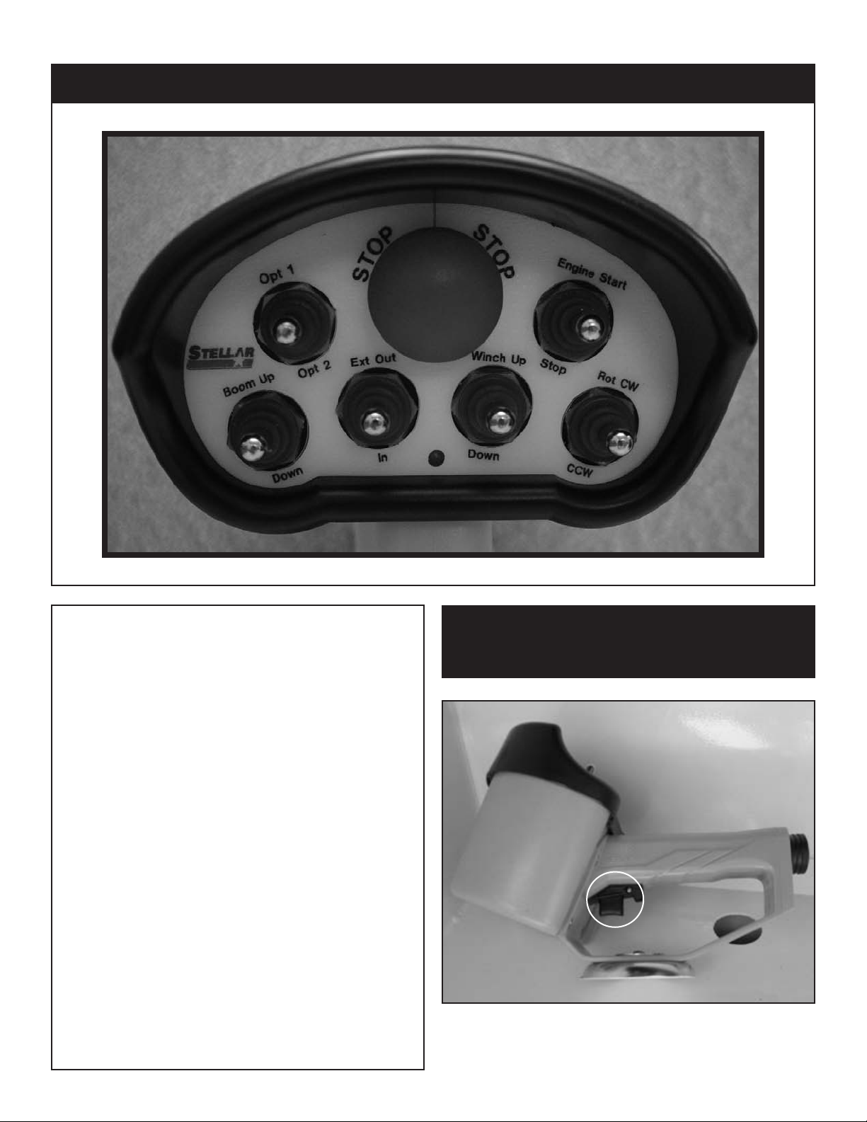
6 Function Hetronic Remote
4.Operate Crane
A. Turn on necessary power to the crane.
B. Activate toggle switch for desired crane
function.
D. Activate the variable speed trigger to
control the desired function.
E. When operation is complete, store
remote handle in a safe, dry location.
5. Store Outriggers
Retract outriggers using the control levers
or switches marked ‘outrigger’.
6. Turn Off Power to Crane
Deactivate power to crane and outriggers.
7. Disengage the PTO
A. On manual transmission vehicles,
depress the clutch pedal completely.
B. Disengage the PTO switch.
C. If vehicle is a manual transmission,
release the clutch pedal gradually.
NOTE: The radio control is an electri-
cal device. Please handle with care!
1
Variable Speed Trigger on remote.
The crane should not function until the trigger has been
activated. The speed of the crane will vary in direct
correlation with how much or how little the trigger is engaged.
Page 11
Operation 7
MAIN
E
XTENSION
E
XTEND
RETRACT
R
OT
CW
MAIN
D
OWN
EXTENSION
D
OWN
ROT
C
CW
UP
U
P
PULL
PUSH
C
ONTROL
F
LOW
WINCH
WINCH
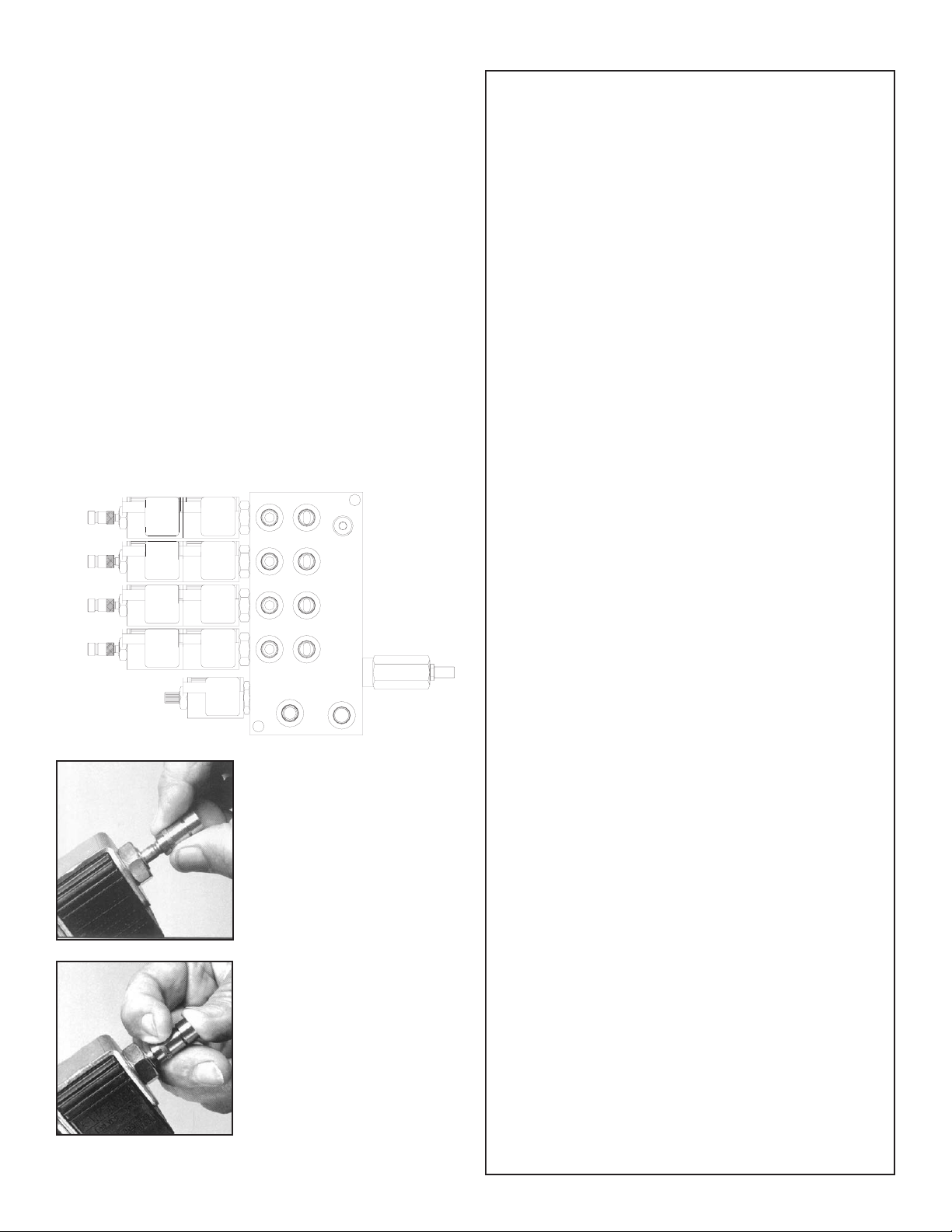
Manual Operation
If the remote control malfunctions, follow
these steps to operate the crane manually:
1. Activate Flow Control. Turn the override
screw on flow control counter-clockwise.
Full adjustment is between three and five
turns.
Operate Solenoids. Slide the knurled sleeve
2.
out and then push or pull to operate, as
shown below. Be sure the sleeve is in the
center, locked, position before returning to
remote operation.
3. Deactivate flow control. Turn the override
screw clockwise until stopped. Full
adjustment is between 3 and 5 turns.
4. Have unit serviced immediately to restore
remote control functionality.
Crane Precautions
1. Movement of the control levers should be
slow and smooth to meter oil flow for safe
operation. Avoid jerky and sudden
movements.
2. The crane controls should be clearly
marked with decals. If these are missing or
illegible,replace immediately. (See Chapter
5: Decals)
3. Lift load slightly off the ground to check the
safety of the cargo. Do not use stability to
determine the safety. Consult the capacity
charts and strictly adhere to them.
4. Be constantly aware of the boom position
when operating the controls.
5. The boom tip should be centered directly
over the load before making the lift to
avoid swinging.
6. Do not drag loads with the crane.
7. Do not attempt to lift fixed loads.
8. Do not load boom in a sideways direction.
9. Know the weight of the rigging and load to
avoid overloading the crane.
10. Do not extend or rotate a load over
anyone.
11. Wear protective gear such as hard hat,
safety glasses, steel-toed boots, and
gloves.
Hook Precautions
1. Hooks are designed and manufactured to
lift specific loads. The specified rated load
of a hook applies to loads held uniformly in
Manual Override Pull
Function
The knurled sleeve is pulled
all the way out together
with the knob to manually
override the pull solenoid
function.
direct tension and does not take into
account shock loads, hook tip loading, side
loading, bending, torsional, or related loads.
2. Do not attempt to lift a load that is larger
than the load rating of the hook.
3. Never use a hook’s yield point as an
indicator of its capacity.
4. Do not use a hook to lift personnel.
5. Know the rated load of the hook in use.
6. Never weld attachments to a finished hook
Manual Override Push
Function
The knurled sleeve should
first be pulled to unlatch the
ball latching mechanism
and then, while holding the
sleeve back, the override
knob should be pushed all
the way in to override the
push solenoid.
in field applications. This will alter and
destroy the design properties of the hook
material.
7. Keep fingers, hands, body, and loose
clothing from between the hook and the
load.
8. Avoid shock loading.
9. Inspect the hook regularly for excessive
wear and maintain it in safe operating
condition.
Page 12

8 10620 Owner’s Manual
Operator Information
OPERATOR REQUIREMENTS
1. Operation is limited to the following
people:
A. Designated individual.
B. Trainees under direct supervision
of the designated individual.
C. Test or maintenance individual.
D. Crane Inspector.
2. Operators must meet the following
physical qualifications:
A. Vision of at least 20/30 Snellen in
one eye and 20/50 in the other,
with or without corrective lenses.
B. Ability to distinguish colors if color
differentiation is required.
C. Adequate hearing, with or
without a hearing aid.
D. No physical or emotional defects
that may create a hazard to the
operator or others.
E. Normal depth perception and
coordination.
3. In addition to the physical qualifications,
Operators must:
A. Demonstrate the ability to
understand all decals, the
owner’s manual, and any other
information required for safe
operation of the crane.
B. Be able to demonstrate the ability
to safely control the crane.
C. Know all safety regulations.
D. Be responsible for maintenance
requirements.
E. Understand and be fully capable
of implementing all emergency
procedures.
F. Understand the operating
procedures as outlined by this
manual, ANSI B30.5, and
Federal/State Laws.
OPERATOR CONDUCT
1. Operators will not engage in any
operation that would cause them to divert
attention away from the operation of the
crane.
2. Operators are responsible for all
operations under their direct control.
3. Operators will not leave a suspended
load unattended.
4. Operators will be familiar with the
equipment and the maintenance required
for proper care.
HANDLING THE LOAD
1. Size of the load:
A. Do not load the crane beyond
the rated capacity.
B. It is the responsibility of the
operator to know the weight of
the handled load.
2. Attaching the load:
A. Attach the load to the hook by
means of slings or other approved
devices.
B. Do not wrap the hoist rope
around the load.
3. Moving the load:
A. Make certain that the crane is
level and properly blocked.
B. Ensure that the load is secure and
balanced within the sling before
moving it.
C. Be sure that the crane is stable
before moving the load. Use
stabilizer pads to ensure the
proper distribution of weight.
D. Do not drag the load sideways.
E. Make sure the hook is brought
over the load to minimize
swinging.
F. No suspended load should pass
over a person.
G. Avoid sudden starts and stops
when moving a load.
Page 13

Chapter 3 - Maintenance
Maintenance 9
WARNING - Read the Following before
performing any maintenance on the
crane.
1. Only authorized service personnel are
to perform maintenance on the crane.
2. Disengage the PTO before any service
or repair is performed.
3. Do not disconnect hydraulic hoses
while there is still pressure in those
components.
4. Before disconnecting hydraulic
components, place the boom on the
ground or have it supported, shut off the
engine, release any air pressure on the
hydraulic reservoir, and move pedals
and control levers repeatedly through
their operating positions to relieve all
pressures.
5. Keep the crane and service body
clean and free from grease build-up, oil
and dirt to prevent slippery conditions.
6. Perform all safety and maintenance
checks before each period of use.
7. Replace parts with Stellar Industries, Inc.
approved parts only.
8. Immediately repair or have repaired
any components found to be
inadequate.
Maintenance Procedures
1. Position the crane where it will be out of
the way of other operations or vehicles in
the area.
2. Be sure boom is lowered to the ground or
otherwise secured from dropping.
3. Place all controls in the off position and
secure operating features from
inadvertent motion.
4. Disconnect power source.
5. Relieve hydraulic oil pressure from all
hydraulic circuits before loosening or
removing hydraulic components.
6. Label or tag parts when disassembling.
Daily Inspection
Daily Inspection should occur each day
before the crane is put into use. Each day,
inspect the crane for all of the following:
1. Hydraulic oil level.
2. Loose parts or damage to structures or
weld.
3. Cylinder movement due to leakage.
4. Hoses and gearboxes for evidence of oil
leaks.
5. Controls, including hand throttle for
malfunction or adjustment.
6. Truck hand brake operation.
7. All securing hardware such as cotter pins,
snap rings, hairpins, and pin keepers for
proper installation.
8. All safety covers for proper installation.
9. Cylinder holding valves for proper
operation.
10. Wire rope for broken wires, extensive
wear, distortion, and heat damage.
Periodic Inspection
Periodic Inspection should occur while the
crane is in use. For the duration of the
usage, inspect the crane for all of the
following:
1. Loose bolts and fasteners.
2. All pins, bearings, shafts, and gears for
wear, cracks, or distortion to include all
pivots, outriggers, sheave pins, and
bearings.
3. Hydraulic systems for proper operating
pressure.
4. Main frame mount bolts.
5. Cylinders for:
A. Damaged rods.
B. Dented barrels.
C. Drift from oil leaking internally.
D. Leaks at rod seals or holding valves.
6. PTO drive line system for proper
alignment, lubrication, and tightness.
7. Hydraulic hose and tubing for evidence of
damage such as blistering, crushing, or
abrasion.
Page 14

10 10620 Owner’s Manual
Weekly Inspection
Weekly Inspection should occur at the
beginning of every work week. Each week,
inspect the crane for all of the following:
1. Lubrication of points required by
lubrication chart located in this chapter.
2. Proper operation of load hook safety
latch.
3. Presence of this owner’s manual.
Monthly Inspection
Monthly Inspection should occur at the
beginning of every work month. Each
month, inspect the crane for all of the
following:
1. Frame bolt tightness - turn barrel nuts and
mounting bolts during the first month of
operation on new machines and then
quarterly thereafter.
2. Cylinders and valves for leaks.
3. Lubrication.
4. Load hook for cracks or having more than
15 percent normal throat opening or 10
degrees twist.
5. Structural members for bends, cracks, or
broken members.
6. All welds for breaks and cracks.
7. All pins and keepers for proper installation.
8. All control, safety, and capacity placards
for readability and secure attachment.
9. Inspect all electrical wires and
connections for worn, cut, or deteriorated
insulation and bare wire. Replace or
repair wires as required.
10. Tightness of all boom wear, pad-retaining
bolts.
Service
The following general suggestions should
be helpful in analyzing and servicing your
crane. Using the following systematic
approach should be helpful in finding and
fixing problems:
1. Determine the problem.
2. List and record possible causes.
3. Devise checks.
4. Conduct checks in a logical order to
determine the cause.
5. Consider the remaining service life of
components against the cost of parts
and labor necessary to replace them.
6. Make the necessary repair.
7. Recheck to ensure that nothing has
been overlooked.
8. Functionally test the new part in its
system.
Inspection Checklist
For a more detailed outline of scheduled
inspection points, refer to the Stellar
Inspection Checklist at the end of this
chapter. This list is an excellent guide for the
inspection tasks that will help maintain the
quality of your Stellar product. Feel free to
photocopy the checklist as needed.
ATTENTION
Every six (6) months,
Stellar Industries recommends the first
filter change to occur after the first 250
hours of service.* The second, and
every subsequent change, should
occur after every 1,000 hours of
service. By following these guidelines,
the hydraulic oil should last up to
6,500 hours.
*Note: These recommendations are based on normal
working parameters. If operating in less than favorable
conditions (excessive dust, moisture, etc.), be sure to check
the filter gauge often for filter change notice.
remove the hydraulic
pump from the PTO and
lubricate the splines using
Chelsea Lubricant #379831
or Stellar PN 20885. Failure
to lubricate shaft splines will
cause damage to the PTO
and Hydraulic pump.
Page 15

Lubrication Recommendations
Component Location Recommendation
Engine Crankcase Apply Manufacturer’s
Recommendations
Maintenance 11
Hydraulic System
Below –5*F
-5*F to 90*F
Above 90*F
Open Gears Hand Precision XL3 Moly EP 2 (NLGI 2 grease
Bearings, grease
(including turntable bearing
inner race)
Worm Drive Gearbox Gearbox Precision Synthetic EP 00 (NLGI 00)
Planetary Gearbox
(including winch)
Reservoir
Petro-Canada Arctic MV 15 (ISO 22)
Petro-Canada HYDREX 32 (ISO 32)
Petro-Canada HYDREX 46 (ISO 46)
with moly)
Gun Precision XL EP 2 (NLGI 2)
Gearbox Traxon Synthetic 75W-90 (API GL-5)
Wear Pad Lubrication Spray Gearshield NC
Compressor Fluids
Reciprocating Single Stage
Reciprocating Double Stage
Screw
-15˚F to 86˚F
-23˚F to 100˚F
32˚F to 113˚F
Crankcase
Crankcase
Crankcase
Compro 100 (ISO 100)
Compro 100 (ISO 100)
Compro XL-S 32 (ISO 32)
Compro XL-S 46 (ISO46)
Compro XL-S 68 (ISO68)
Greasing the Crane
Lubricate all grease gun points with
Extreme Pressure Grease - Stellar P/N: 22059.
Page 16

12 10620 Owner’s Manual
Wire Rope Maintenance
Wire Rope Inspection Points
While inspection of the entire rope is
required, attention should be directed to
these critical points:
1. Pick-up Points for signs of wear due to
stress from repeated lifts.
2. End Attachments for corrosion and broken
wires at both ends of the rope.
Drums for signs of corrugation and wear
3.
that may lead to wire damage.
Sheaves to ensure that each sheave has
4.
the proper groove size and contour.
5. Abuse Points for heavy amounts of
scuffing and scraping.
It is important to perform detailed
inspections of all ropes associated with the
crane. These inspections can be divided
into two types:
1. Frequent Inspection
A. All running ropes should be inspected
once each working day. These visual
observations will be concerned with
discovering damage that may be an
immediate hazard. The following
concerns should be addressed:
1. Distortion of the rope.
2. General corrosion.
3. Broken or cut strands.
B. Use caution while inspecting sections of
rapid deterioration.
C. Use caution while inspecting boom
hoist ropes. Proper inspection is critical
but difficult.
Periodic Inspection
2.
A. Inspection frequency will be
determined by a qualified person and
will be based on such factors as
expected rope life, environment
conditions, capacity of typical lifts,
rates of usage, and exposure to shock
loads. Periodic inspection needs to be
performed at least annually.
B. Periodic inspections will be performed
by a qualified individual and will cover
the entire length of the rope. Only the
surface wires of the rope need to be
inspected. This inspection will be
concerned with discovering damage
that may be an immediate hazard. The
following concerns should be
addressed:
1. Distortion of the rope.
2. General corrosion.
3. Broken or cut strands.
4. Reduction of rope diameter.
5. Corroded or broken wires at end
connections.
6. Corroded, cracked, bent, worn, or
improperly applied end
connections.
C. Use caution when inspecting the
following:
1. Sections in contact with saddles,
equalizer sheaves, or other sheaves
where rope travel is limited.
2. Sections of the rope at or near ends
with corroded or broken wires.
Wire Rope Replacement
Rope replacement guidelines are as follows:
1. Broken wires, including standing ropes
with more than two broken wires in one
lay or more than one broken wire at an
end connection.
2. Wear of one-third the original diameter of
the outside wires.
3. Distortion of the rope structure.
4. Evidence of heat damage.
5. Reductions from nominal diameters of
more than 1/64 in. (0.4 mm) for diameters
from 5/16 in.(19.0 mm) and 1/32 in. (0.8
mm) for diameters from 3/8 in. (9.5 mm) to
and including 1/2 in. (13.0 mm).
Wire Rope Maintenance
Proper maintenance is key in ensuring a
long lasting rope. These three tips will help:
1. Store the rope to prevent damage.
2. Avoid objects that may scrape, bend, or
crush the wires of the rope.
3. Always keep the rope well-lubricated.
Page 17
Holding Valve Inspection Procedure
The cylinders are equipped with holding
valves that prevent sudden movement of
the cylinder rods in the event of a hydraulic
hose or hydraulic component failure. The
valve is checked in the following manner:
1. Identify the cylinder in question.
2. Identify the holding valves and the
cylinder direction in question.
a. Cylinder Extend.
b. Cylinder Retract.
3. Place the machine so that the cylinder
will be located in the appropriate testing
position.
4. Pick the load (Do not exceed capacity,
rated or stability).
5. Disengage hydraulics.
6. Operate crane functions.
A. If the cylinder creeps (lowering the
load), replace the holding valve.
B. If the cylinder does not creep (load
stays suspended), the valve is
operational.
Maintenance 13
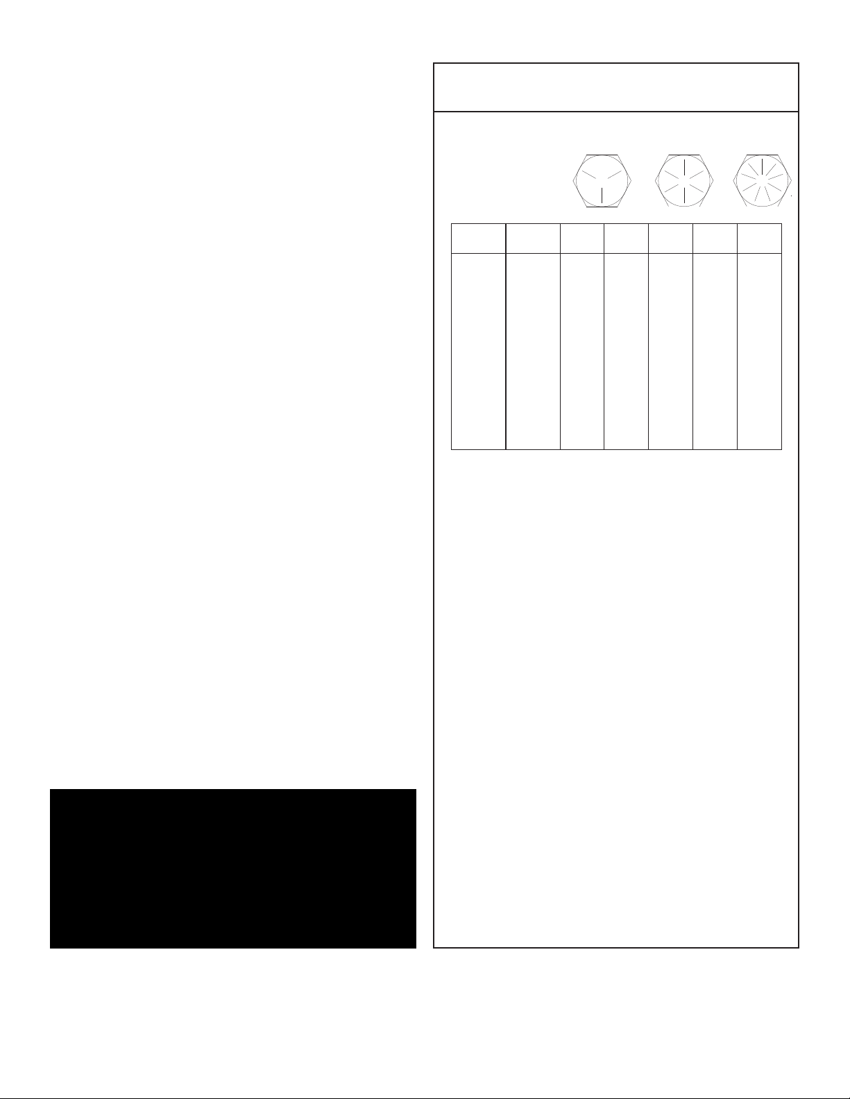
Torque Data Chart
Grade 5
Plated
Size
(DIA-TPI)
5/16-18
3/8-16
7/16-14
1/2-13
9/16-12
5/8-11
3/4-10
7/8-9
1-8
1 1/8-7
1 1/4-7
1 3/8-6
1 1/2-6
Bolt DIA
(Inches)
0.3125
0.3750
0.4375
0.5000
0.5625
0.6250
0.7500
0.8750
1.000
1.1250
1.2500
1.3750
1.500
Plain
(Ft-Lb)
17
31
49
75
110
150
265
395
590
795
1120
1470
1950
(Ft-Lb)
13
23
37
57
82
115
200
295
445
595
840
110
1460
When using the torque data in the charts
above, the following rules should be
observed.
Grade 8
Plain
(Ft-Lb)
25
44
70
105
155
220
375
605
910
1290
1815
2380
3160
Plated
(Ft-Lb)
18
33
52
80
115
160
280
455
680
965
1360
1780
2370
Grade 9
Plated
(Ft-Lb)
22
39
63
96
139
192
340
549
823
1167
1646
2158
2865
Gear-Bearing Bolt Maintenance
Anytime a gear-bearing bolt is removed, it
must be replaced with a new bolt of the
identical grade and size. Once a bolt has
been torqued to 75% of its proof load and
then removed, the torque coefficient may
no longer be the same as when the bolt was
new thus giving indeterminate damp loads
after torquing.
Warning!
Failure to replace gear-bearing
bolts may result in bolt failure due
to metal fatigue causing serious
injury or even death.
1. Bolt manufacturer’s particular
specifications should be consulted when
provided.
2. Flat washers of equal strength must be
used.
3. All torque measurements are given in
foot-pounds. To convert to inch-pounds,
multiply by 12.
4. Torque values specified are for bolts with
residual oils or no special lubricants
applied. If special lubricants of high stress
ability, such as Never-Seez compound
graphite and oil, molybdenum disulphite,
colloidal copper or white lead are
applied, multiply the torque values in the
charts by the factor .90. The use of Loctite
does not affect the torque values listed
above.
5. Torque values for socket-head capscrews
are the same as for Grade 8 capscrews.
Page 18
14 10620 Owner’s Manual
Inspection Checklist
Use of this checklist is subject to terms of the
Stellar Warranty information. Additional copies of
this checklist can be obtained by contacting
Stellar Customer Service at (800) 321-3741.
Owner/Company:
Contact Person:
Crane Make/Model:
Crane Serial:
Type of Inspection (check one)
Daily (if deficiency found)
Monthly
Date Inspected:
Hour Meter Reading:
Inspected by: (
Signature of Inspector:
print)
Quarterly
Annual
Type of Inspection Information
Daily and monthly inspections are to be performed by a “designated” person, who has
been selected by the employer or the employer’s representative as being competent to
perform specific duties.
Quarterly and annual inspections are to be performed by a “qualified” person who, by
possession of a recognized degree in an applicable field or certificate of professional
standing, or who, by extensive knowledge, training and experience has successfully
demonstrated the ability to solve or resolve problems related to the subject matter and
work.
One hour of normal crane operation assumes 20 complete cycles per hour. If operation
exceeds 20 cycles per hour, inspection frequency should be increased accordingly.
Consult the Stellar Owner’s Manual for additional inspection items.
Before inspecting and operating the crane, make certain that t he crane is set up away
from power lines and leveled with outriggers fully extended.
Daily (D): Before each day of operation, those items with a (D) must be inspected. This
inspection need not be recorded unless a deficiency is found.
Monthly (M): Monthly inspections or 100 hours of normal operation (which ever comes
first) includes all daily and monthly inspection items plus items designated with a (Q). This
inspection must be recorded.
Quarterly (Q): Every three months or 300 hours of normal operation (which ever comes
first) includes all daily and monthly inspection items plus items designated with an (M).
This inspection must be recorded.
Annual (A): Each year or 1200 hours of normal operation (which ever comes first) includes
all items on this form which encompasses daily, monthly, and quarterly inspections plus
those items designated by (A). this inspection must be recorded.
Page 19

Daily Inspection
Maintenance 15
Frequency
D
D
D
D
D
D
D
D
D
D
D
Key
Decals
Controls
Station
Hydsystem
Hook
Rope
Pins
General
Operation
Remote Ctrls
Electrical
Inspection Description
All load charts, safety & warning Decals, & control Decals are present and
legible.
Check all safety devices for proper operation.
Control mechanisms for proper operation of all functions, leaks, & cracks.
Control mechanisms for proper operation of all functions, leaks, & cracks.
Hydraulic system (hoses, tubes, & fittings) for leakage & proper oil level.
Presence & proper operation of hook safety latches.
Proper reeving of wire rope on sheaves & winch drum.
Proper engagement of all connecting pins & pin retaining devices.
Overall observation of crane for damage or missing parts, cracked welds &
presence of safety covers.
During operation, observe crane for abnormal performance, unusual wear.
If observed, discontinue use & determine cause & severity of hazard.
Operate remote control devices to check for proper operation.
Operate all lights, alarms, etc. to check for proper operation.
Status
D
D
D
Anti 2-Blocking
Operation Aid
Operation Aid
Operate anti 2-blocking device to check for proper operation.
Check presence of boom angle indicator.
Check overload device for proper operation.
Page 20

16 10620 Owner’s Manual
Monthly Inspection
Frequency
M
M
M
M
M
M
M
M
M
M
M
M
Key
Daily
Cylinders
Valves
Valves
Valves
General
Electrical
Structure
Welds
Pins
Hardware
Wear Pads
Inspection Description
All Daily Inspections.
Visual inspection of cylinders for leakage at rod, fittings, & welds. Damage
to rod & case.
Holding valves for proper operation.
Control valve for leaks at fittings & between sections.
Control valve linkages for wear, smoothness of operation & tightness of
fasteners. Relief valve for proper pressure settings.
Bent, broken or significantly rusted/corroded parts.
Electrical systems for presence of dirt, moisture & frayed wires.
All structural members for damage.
All welds for breaks & cracks.
All pins for proper installation & condition.
All bolts, fasteners & retaining rings for tightness, wear & corrosion.
Condition of wear pads.
Status
M
M
M
M
M
M
M
M
M
M
Pump & Motor
PTO
Hyd Fluid
Hyd Lines
Hook
Rope
Manual
Chassis
Chassis
Station
Hydraulic pumps & motors for leakage at fittings, seals & between sections.
Check tightness of mounting bolts.
Transmission/PTO for leakage, abnormal vibration & noise, alignment &
mounting bolt torque.
Quality of hydraulic fluid and for presence of water.
Hoses & tubes for leakage, abrasion damage, blistering, cracking,
deterioration, fitting leakage, & secured properly.
Load hook for abnormal throat distance, twist, wear, & cracks.
Condition of load line.
Presence of operator's manuals with the unit.
Tire wear and air pressure.
Working backup alarm.
Fire extinguisher at cab or machinery housing.
Page 21

Quarterly Inspection
Maintenance 17
Frequency
Q
Q
Q
Q
Q
Key
Daily
Monthly
Rotation Sys
Hardware
Structure
Inspection Description
All daily inspections.
All monthly inspections.
Rotation bearing for proper torque of all mounting bolts.
Base mounting bolts for proper torque.
All structural members for deformation, cracks, & corrosion.
Base
Outrigger beams & legs
Mast
Inner boom
Outer boom
Extension(s)
Jib boom
Status
Q
Hardware
Jib extension(s)
Other
Other
Pins, bearings, shafts, gears, rollers, & locking devices for wear, cracks,
corrosion, & distortion.
Inner boom pivot pin(s) & retainer(s)
Outer boom pivot pin(s) & retainer(s)
Inner boom cylinder pin(s) & retainer(s)
Outer boom cylinder pin(s) & retainer(s)
Extension cylinder pin(s) & retainer(s)
Jib boom pin(s) & retainer(s)
Jib cylinder pin(s) & retainer(s)
Jib extension cylinder pin(s) & retainer(s)
Boom tip attachments
Other
Other
Page 22

18 10620 Owner’s Manual
Quarterly Inspection Continued...
Frequency
Q
Q
Q
Key
Hyd Lines
Pumps&Motors
Valves
Inspection Description
Hoses, fittings, & tubing for proper routing, leakage, blistering, deformation,
& excessive abrasion.
Pressure line(s) from pump to control valve
Return line(s) from control valve to reservoir
Suction line(s) from reservoir to pump
Pressure line(s) from control valve to each function
Load holding valve pipe(s) and hose(s)
Other
Pumps and motors for loose bolts/fasteners, leaks, noise, vibration, loss of
performance, heating and excess pressure.
Winch motor(s)
Rotation motor(s)
Other
Hydraulic valves for cracks, spool return to neutral, sticking spools, relief
valve failure.
Main control valve
Status
Q
Q
Q
Cylinders
Winch
Hyd Filter
Load holding valve(s)
Outrigger or auxiliary control valve(s)
Other
Hydraulic cylinders for drifting & leakage. Rods for nicks, scores, & dents.
Castor damage. Case & rod ends for damage & abnormal wear.
Outrigger cylinder(s)
Inner boom cylinder(s)
Outer boom cylinder(s)
Extension cylinder(s)
Rotation cylinder(s)
Jib lift cylinder(s)
Jib extension cylinder(s)
Other
Winch, sheaves, & drums for damage, abnormal wear, abrasion, & other
irregularities.
Hydraulic filters for replacement per maintenance schedule.
Page 23

Annual Inspection
Maintenance 19
Frequency
A
A
A
A
A
A
A
A
A
A
A
A
Key
Daily
Monthly
Quarterly
Hyd System
Controls
Valves
Valves
Rotation Sys
Lubrication
Hardware
Wear Pads
Loadline
Inspection Description
All daily inspection items.
All monthly inspection items.
All quarterly inspection items.
Hydraulic fluid change per maintenance schedule.
Control valve calibration for correct pressures & relief valve settings.
Safety valve calibration for correct pressures & relief valve settings
Valves for failure to maintain correct settings.
Rotation drive system for proper backlash clearance & abnormal wear,
deformation, & cracks.
Gear oil change in rotation drive system per maintenance schedule.
Check tightness of all fasteners and bolts.
Wear pads for excessive wear.
Loadline for proper attachment to drum.
Status
A
A
A
Historic Data
Historic Data
Historic Data
Monthly inspection records.
Maintenance records.
Repair and modification records.
Page 24

20 10620 Owner’s Manual
Inspection Notes
Page 25

Chapter 4 - Specifications
Model 10620 Crane
SPECIFICATION SHEET
Crane Rating: 55,000 ft-lbs (7.60 ton-meters)
Standard Boom Length: 10’ 9"(3.28 m) from CL of Crane
Boom Extension: 1st stage: Hydraulic 60"(152.4 cm)
2nd stage: Hydraulic 60"(152.4 cm)
Maximum Horizontal Reach: 20’9"(6.32 m) from CL of Crane
Maximum Vertical Lift: 22’(6.71 m)
(from crane base)
Boom Elevation: -5 to +80 degrees
Specifications 21
Stowed Height 34” (86.4 cm)
(crane only)
Mounting Space Required 20 x 21 inches (50.8 x 53.3 cm)
Approximate Shipping Weight 2150 lbs (975 kg)
Controls Radio control standard
for all functions.
Winch Specification
Rope Diameter: 7/16" (1.11 cm)
Line pull speed: 60 ft/min (18.29 m/min)
Max. single part line: 5000 lbs (2268 kg)
Max. double part line: 10000 lbs (4535 kg)
Rotation: 400 degree power
(worm gear)
Lifting Capacities 5100 lbs @ 10’9"(2315 kg @ 3.28m)
3475 lbs @ 15’9"(1575 kg @ 4.80m)
2650 lbs @ 20’9"(1200 kg @ 6.32m)
Power Supply Required PTO & Pump
(8 gpm @ 3000 psi)
(30.3 lpm @ 207 bars)
*Subject to change without notification
Page 26

22 10620 Owner’s Manual
Reach in Feet/Meters
Capacity in Pounds/Kilograms
Weight of load handling devices are
part of the load lifted and must be
deducted from the capacity.
Maximum 1 - part line capacity is
5000lbs (2270kg). For greater
loads, use 2 - part line.
5100lbs
2315kg
3475lbs
1575kg
2650lbs
1200kg
5175lbs
2350kg
3550lbs
1610kg
5625lbs
2550kg
2700lbs
1225kg
6675lbs
3030kg
3900lbs
1770kg
2975lbs
1350kg
8850lbs
4015kg
4650lbs
2110kg
3575lbs
1620kg
10000lbs
4535kg
10000lbs
4535kg
10000lbs
4535kg
9
450lbs
4285kg
6300lbs
2880kg
9350lbs
4240kg
7750lbs
3315kg
4900lbs
2
225kg
PN 16004
10620
Capacity Chart - Decal PN 16004
Page 27

Chapter 5 - Decals
Decals of Note
Foot Crushing Hazard Decal
Location: On each outrigger leg.
Function: To inform the operator and other
personnel in the work area of the hazard
associated with the operation of the outriggers,
the possible consequences should the hazard
occur, and how to avoid the hazard. PN: C4795
Decals 23
Instructional Decal
Location: At Stow Hook area
Function: To caution the operator not to use the
stow hook for any lifting applications. PN: 24712
Moving Outrigger Hazard Decal
Location: On each outrigger
Function: To inform the operator of the hazard
associated with outrigger operation, the possible
consequences should the hazard occur, and how
to avoid the hazard
. PN: C5918
Page 28

24 10620 Owner’s Manual
Electrocution Hazard Decal
Location: Each side of truck body, Front & Rear
Bumper
Function: To inform the operator and other
personnel in the work area of the hazard
associated with contact or proximity to electrical
lines, the possible consequences should the hazard
occur and how to avoid the hazard.
PN: C4545
Page 29

Decals 25
Two Block Hazard Decal
Location: At Boom Tip
Function: To inform the operator of the hazard
associated with bringing the sheave(s) into
contact with the hook, snatch block or load, the
possible consequences should the hazard occur
and how to avoid the hazard. PN: 12300
Instructional Decal
Location: At Overload Switch
Function: To inform the operator that
tampering with the overload device may
cause a unit failure.
PN: 28256
Page 30

26 10620 Owner’s Manual
Free Falling Manual Boom Decal
Location: Inside Crane Compartment, on
Compartment Door
Function: To inform the operator of the hazard
associated with free falling manual boom
extensions, the possible consequences should
the hazard occur, and how to avoid the
hazard.
PN: 12452
Electrocution Hazard Decal
Location: Inside Crane Compartment, on
Compartment Door
Function: To inform the operator of the hazard
associated with overloading the crane, the
possible consequences should the hazard
occur, and how to avoid the hazard.
PN: C1179
Operation Hazard Decal
Location: Inside Crane Compartment, on
Compartment Door
Function: To inform the operator and other
personnel in the work area of the hazard
associated with improper maintenance and
unauthorized modifications, the possible
consequences should the hazard occur, and
how to avoid the hazard.
PN: 4190
Operation Hazard Decal
Location: Inside Crane Compartment, on
Compartment Door
Function: To inform the operator of the hazard
associated with overloading the crane, the
possible consequences should the hazard
occur, and how to avoid the hazard.
PN: 4189
Page 31

Decals 27
Moving Boom Hazard Decal
Location:Inside Crane Compartment, on
Compartment Door
Function: To inform the operator and other
personnel in the work area of the hazard
associated with a moving boom, especially
while stowing and unfolding the crane, the
possible consequences should the hazard
occur, and how to avoid the hazard.
PN: C4541
Operation Hazard Decal
Location:Inside Crane Compartment, on
Compartment Door
Function: To inform the operator of the need
for proper training, familiarity with safe
operating procedures and, the possible
consequences without training.
PN: C4540
Hoisting Decal:
Location: Inside Crane Compartment, on
Compartment Door
Function: To inform the operator of the hazard
associated with lifting personnel with the boom,
boom hook, the load or winch loadline, the
possible consequences of lifting personnel, and
how to avoid the hazard.
PN: 12451
Training Decal:
Location:Inside Crane Compartment, on
Compartment Door
Function: To inform the operator of the need
for proper training, familiarity with safe
operating procedures, and the possible
consequences of operation without training.
PN: C4544
Page 32

28 10620 Owner’s Manual
PN 15999
Decal Kit Placement - PN 15999
Page 33

Installation 29
Chapter 6 - Installation
Notice: Read this Page Before Installation of the Crane
General Installation
This chapter is designed to serve as a
general guide for the installation of a Stellar
10620 Telescopic Crane on a Stellar Service
Body. Each installation is considered unique
so certain portions of this chapter may or
may not apply to your direct application. If
a question should arise during the installation
process, please contact Stellar Customer
Service at (800) 321 3741.
This crane is designed for use with a Stellar
Service Body installed on a vehicle that
meets the minimum chassis requirements of
the crane. Check with Stellar Industries
before installing this crane on a body other
than a Stellar Service Body.
WARNING!
The use of this crane on a
body not capable of
Installation Notice
According to Federal Law (49 cfr part 571),
each final-stage manufacturer shall
complete the vehicle in such a manner that
it conforms to the standards in effect on the
date of manufacture of the incomplete
vehicle, the date of final completion, or a
date between those two dates. This
requirement shall, however, be superseded
by any conflicting provisions of a standard
that applies by its terms to vehicles
manufactured in two or more stages.
Therefore, the installer of Stellar cranes and
bodies is considered one of the
manufacturers of the vehicle. As such a
manufacturer, the installer is responsible for
compliance with all applicable federal and
state regulations. They are required to
certify that the vehicle is in compliance with
the Federal Motor Vehicle Safety Standards
and other regulations issued under the
National Traffic and Motor Vehicle Safety
Act.
handling the loads
imposed on it may result
in serious injury or death.
Optimal Service Body
for the 10620 Crane:
T3-11 Service Body
Applicable Chassis: 19000 GVWR and up.
Cab to Axle: 84” (213.36 cm)
Body Length Nominal: 133” (337.82 cm)
Body Height: 52” (132.08 cm)
Body Width: 94” (238.76 cm)
Compartment Depth: 22” (55.88 cm)
Floor Width: 50” (127 cm)
Net Weight: 3600 lbs (1632.93 kg)
Please reference the Code of Federal
Regulations, title 49 - Transportation, Volume
5 (400-999), for further information, or visit
http://www.gpoaccess.gov/nara/index.html
for the full text of Code of Federal
Regulations.
Notice:
PTO and Pump installation instructions are
provided by the corresponding
manufacturers. For more information on
which PTO and Pump fit your application,
please contact your local Stellar Distributor
or Stellar Customer Service.
The following pages will give a basic
overview of the installation process for the
Stellar 10620. Please read through them
entirely and obtain a clear understanding of
the process before proceeding.
Page 34

30 10620 Owner’s Manual
WASHER 1.00 SAE FLAT YELLOW G8
CAP SCR 1.00X8X3.00 HHGR8 ZY
DESCRIPTIONPART NO.ITEM NO.
2
1
6538
5199
QTY.
6
6
1
2
FRONT
Motor
Hole Mounting Detail
Ø1.063
6.88
13.75
2.38
7.38
14.75
7.38
14.75
6 Places
Ø6.00
Installation Overview
1. Determine that the mounting location for the 10620 crane is at least 20” x 21” (50.8 x 50.8 cm).
2. Use the detail below to drill 1.06” diameter holes into the mounting plate. Run tap on the threads of the
base to be sure they are clean.
3. Use a crane or lifting device capable of lifting the weight of the Stellar crane. The Stellar 10620 weighs
approximately 2150 lbs (975 kg).
degree system. This will allow for easy installation of the crane and permanent connection of all hydraulic
and electrical components prior to repositioning into the crane saddle.
4. Connect straps or chain from the lifting device to the lifting rings on the Stellar 10620.
5. Use six (6) 3” x 1” #8 bolts and six (6) #8 flat washers.
6. Install a washer on each bolt.
7. Apply Loctite Thread locker #277 to the bolts.
8. Using the lifting device, lower the Stellar 10620 just above the crane compartment and start the bolts.
Have someone assist in leveling the crane.
compartment and the boom should be extended back over the rear bumper.
9. Secure the crane using the mounting hardware provided. Note: longer or shorter cap screws may be
required – recommended thread engagement into crane base is 1.75” – use grade 8, zinc plated cap
screws only.
10. Torque the cap screws to 680 ft-lbs.
11. Remove supporting crane.
12. Hook-up hydraulics and electrical using the schematics provided in
Note: If questions should arise during any portion of this installation, please contact Stellar Customer
Service at (800) 321-3741.
Note: cranes are shipped with rotation positioned at 200 degrees of 400
Note: the rotation motor should be to the door side of crane
Chapter 8 - Hydraulics - Electrical.
Page 35

Installation 31
Installation Details
1. Determine that the
mounting location
for the 10620 crane
is at least 20” x 21”
(50.8 x 50.8 cm).
2. Use the detail on the
previous page to
drill 1.06” diameter
holes into the
mounting plate. Run
tap on the threads
of the base to be
sure they are clean.
3. Use a crane or lifting device capable of lifting the weight of the Stellar crane. The Stellar
10620 weighs approximately 2150 lbs (975 kg).
positioned at 200 degrees of 400 degree system.
crane and permanent connection of all hydraulic and electrical components prior to
repositioning into the crane saddle.
Note: cranes are shipped with rotation
This will allow for easy installation of the
4. Connect straps or chain from the lifting device to the
lifting rings on the Stellar 10620.
5. Use six (6) 3” x 1” #8 bolts and six (6) #8 flat washers.
6. Install a washer on each bolt.
7. Apply Loctite Thread locker #277 to the bolts.
The number of bolts used may
vary from model to model
8. Using the lifting device, lower the Stellar 10620 just
above the crane compartment and start the bolts.
Have someone assist in leveling the crane.
rotation motor should be to the door side of crane
compartment and the boom should be extended
back over the rear bumper.
Note: the
Page 36

32 10620 Owner’s Manual
Installation Details Continued...
9. Secure the crane using the mounting
hardware provided.
cap screws may be required –
recommended thread engagement into
crane base is 1.75” – use grade 8, zinc
plated cap screws only.
10. Torque the cap screws to 680 ft-lbs.
Note: longer or shorter
11. Remove supporting crane.
12. Hook-up hydraulics and electrical using the schematics provided in
Hydraulics - Electrical.
Note: If questions should arise during any portion of this installation, please contact Stellar
Customer Service at (800) 321-3741.
Chapter 8 -
Page 37

Installation 33
Stability Procedure
Definition of Stability for the Stellar Telescopic Crane Products:
A truck is stable until the load cannot be lifted off the ground with the winch, without
tipping over the truck. Every Stellar crane installed must be tested for stability to
determine the actual load capacity of the final truck package. The actual test data
must be recorded and supplied with the truck at the time of in-service and should be kept
with the truck at all times. The following procedure will test the truck package for stability
and will provide a stability capacity chart. The load limit information shown on the
stability capacity chart is formulated on 85% tipping.
Set Up:
1. Locate the truck on a test course in position for loading and engage travel brakes.
2. Set outriggers so that they make contact with firm, level footings.
3. Operate the crane under partial load to assure operator proficiency and proper
machine function.
10620 Stability Data
Max Horizontal Reach: 249” (From the center of rotation to boom tip)
Stability Test Weight: 3125 lbs.
Test Procedure
1. Rotate the crane into Zone 1 position.
2. With the crane fully retracted and the boom horizontal, winch the test weight off the
ground. Note: Keep weight within six inches of the ground at all times.
3. Extend the boom outward until full extension has been reached or until the truck
becomes unstable (Again, use the winch to keep the weight within six inches of the
ground.)
4. If the boom goes full extension without becoming unstable, the crane is termed stable
for this zone and 100% can be written in the Zone 1 data box.
5. If the truck becomes unstable prior to going full extension, retract the boom until the
truck becomes stable and measure the horizontal reach in this position (center of
rotation to boom tip). This is the stable horizontal reach for this zone. Stable horizontal
reach divided by Maximum horizontal reach multiplied by 100 equals the percentage
of rated capacity for this zone. Use the following formula to determine the percentage
of rated capacity:
6. Record this number in the data box for Zone 1. This is the revised capacity due to
stability for this zone.
7. Repeat this procedure for each zone until the worksheet is completed.
8. This is the revised capacity based on stability of this package.
Page 38

34 10620 Owner’s Manual
STABILITY CAPACITY CHART
Stability Capacity Chart
For a decal version of this capacity chart, please contact Stellar Customer Service at (800) 321-3741
Page 39

Assembly Drawings 35
10
11
8
7
5
1
6
2
3
4
9
GASKET SHOWN AS REFERENCE
13
12
10
.YTQNO
ITPI
RCSEDTRAPMETI
1 11453 BEARING SWING DRIVE CAST BASE 6620 1
1EDILS 004 0283
POTS2
4511
2
3C6069 MOTOR HYD ROSS MK080613AAAB 1
4D1307 CAP SCR 0.50-13X1.25 SH 2
1ENARC 0266 BTT DRAUG037215
613959 CAP SCR 1.00-8 X .63 PLASTIC 2
2
TALF 52.
0 REHSAW043
0
7
8 0479 CAP SCR 0.25-20X0.75 HHGR5 2
9 21151 GASKET MOTOR 008-10056-1 1
10 D1345 FTG CPRSN 0.12NPT/0.25 TUBE 2
11 D1810 TBE AIR SAEJ844 TYPE A .25 (28") 1
131.0 EPIP RELPUOC GTF6522C21
1
TH
GIARTS TPN 8/1 KREZ2951c31
P/N 18027
Chapter 7 - Assembly Drawings
Base Assembly - PN 18027
Page 40

36 10620 Owner’s Manual
0 1
1
1
1
1
2 1
5
3
4
4
1
4
1
5
1
4
1
3
1
7
6
8
1
2
9
6
1
7
1
9
1
8 1
. Y
T Q
N O I
T P I R C
S E D T
R A
P
M E T I
1 E N A R C 0 2 6 9
T S
A M 7 6 9 2
1
1
1 0 0 0 5 H C N I W 8 6 9 2 1
2
4 1 8 R
G
W
O
L L E Y T A
L
F
E A S
3 6 .
0
R E
H
S A W 2
0
9 5 C 3
4 1 Y Z 8 R G H H 0 0 . 3 X 1 1 - 3 6 . 0 R C S P A C 4 3 0 1 D 4
4 K C O L R A G 0 0 . 2 X 0 0 . 2 2 3 R X D 2 3
G
N
I
H S U B 1 8 3 4 5
8
8 R G
T A L F
0 5
. 0 R E H
S A
W 0 9 7
0 D 6
4 Y
Z 8 R G
H H 0 5 .
2 X 3 1 - 0
5 . 0
R C S P A C 2 6 6
0 1 7
4 C O L Y N 5 R G H H 3 1 -
0 5 .
0
T
U N 6 0 1
6
C 8
1 M P G 8 G N I L R E T S P O R P / W T C E L E T C E S 4
B
V 5 8 6 4 2
9
2
5 R
G H
H
5 7 . 3 X 8 1 - 1 3 . 0 R C S P A C 9 3
1 4
2 0
1
4 C N I Z T A L F S S U 1 3 . 0 R E H S A W 3 4 3
0
1 1
2
C O L Y N H H 8 1 - 1 3 . 0 T U N 2 4 3 0 2 1
1 T
S A M 0 2 6 9
R
E
V O C 1 9 3 3 1 3 1
8 T A L F 5 2 . 0 R E H S A W 0 4 3 0
4
1
4 5 R G H H 5 7 . 0 X 8 1 - 1 3 . 0 R C S P A C 0 2 4 0 5 1
2 W M H U 8 3 . 0 X 5 7 . 0 X 8 3 . 0 R A L L O C
3 1
8 7 2 6
1
1 2
H N
T C F
6
L O R T
N O C O
I D A R
R E
V I E C E R 3 0
1 4
3 7 1
2 5 R G H H 0 5 . 1 X 0 2 - 5 2 . 0 R C S P A C 0 2 2 0 8 1
2 C O L Y N 5 R G H H 0 2 - 5 2 . 0 T U N 3 3 3 0 9 1
P/N 18028
Mast Assembly - PN 18028
Page 41

4 2
2
2
7
3 2
9
5
8
7
6
6
7
6
7
8
8
4 1
3 1
2
1
1
1
4
2
6
7
7
6
0 1
3
7 2
0
2
9 1
7
1
8 1
1 2
3 1
0
2
7
3
5 1
7
6 1
5 2
6
2
8
2
1
9 2
.
Y
T
Q N
O I T P I
R C S E D
T R
A P M E
T I
1
0
2
6 9
R
E N
N I M O O B 3 7 7 4 3 1
1 R
E
N N I 0 2 6 9 M S A R E D N I L Y C 4 4 1 4 2 2
4
K C O L R A G
0
0 . 2 X
0
0
.
2 2
3
R
X D
2 3 G N I
H
S U
B
1 8 3 4 3
2
4 2 - 8 1 6 1 - I S Q G
N I H S U B 8 6 0
0
4
1
T & D 9 1 . 1 1 X 0 0 . 2 N I P 3 6 3 3 1 5
6
5 2 .
X
0
5 . 3 X 6 5 . 0 P A C N I P 7 7 3 8
6
8 1
8
R G T A L F 0 5 . 0 R E H S A W 0 9 7 0 D 7
6 Y
Z
8 R G H H 0 0 . 1 X 3 1 - 0 5 . 0 R C S P A C 2 7 1 0
1
8
1 T & D 8
8
. 8 X 0 0
.
2
N I
P
1 1 7 9 9
1 T
&
D
9
6
. 2 1 X 0 0 . 2 N I P 4 6 3 3
1
0
1
. Y T Q
N
O I
T
P I R C S
E
D T R A P
M
E
T I
1 T & D 8 3 . 8 X 0 0 . 1 N I P 2 1 7 9 1 1
2 2 5 2 . X 0 5 . 2 X 4 4 .
0
P A
C
N I P 3 0 4 7 2 1
6
8 R G T
A
L F 8 3
.
0 R E H S A W 3 5 3 6 C
3 1
2
8 R G H H 5 7 . 0 X 6
1 -
8 3 . 0 R C S P A C 3 4 8 9 4 1
2 R O T A C I D N I E L G N A E T A L P 4 9 1 1 D 5 1
2 C O L Y N 5 R G H H 3 1 - 0 5 . 0 T U N 6 0 1 6 C 6 1
1 0 2 6 9
E
D I U G E P O R T K R B 5 3 4 3 1 7 1
2
5
R G H H 0 0 . 9 X 6 1 - 8 3 . 0 R C S P A C 8 6 1 2 1 8 1
2 W M H U 0 2 6 6 E D I U G E P O R R E C A P S 0 2 7 7
2 9
1
4 C O L Y N H H 6 1 - 8 3 . 0 T U N 7 4 3 0 0 2
. Y T Q N O I T P I R C S E
D
T
R
A P M E T I
2 5 R G H H 5 2 . 1 X 6 1 - 8 3 . 0 R C S P A C 5 3 3 0 1 2
2 0 2 6
9
T R O P P U S D A P R A E W E T
A L
P 8 9 3 3 1 2 2
8 8 R G H H 5
2 .
1 X 3 1 - 0 5 . 0 R C S P A C 6 6 6
0
1 3 2
2 N
O R T A L Y
N
0 0
.
1 X 0
0
.
3 X 0 0 . 3
D
A P R A E
W 5
9 3
3
1 4 2
2
T
A L F 5 2 . 0 R E H S A W 0 4 3 0 5 2
1 L Y N I
V K L
B 5 2 . 0 P
M A L
C 6 0 6 5 C 6 2
1 0 2 6 6 L E E R D R O C 4 4 5 1 1 7 2
2
5 R G H H 0 5 . 0 X 0 2 - 5 2 . 0 R
C S
P A C 8 7 4 0 8 2
2 8 8 . 2 X 8 8 . 2 X 5 2
.
0 L A E T A L P 1 5 4 5 3 9 2
P/N 18029
Main Boom - PN 18029
Assembly Drawings 37
Page 42

38 10620 Owner’s Manual
9
01
8
7
01
51
6
31
41
11
21
5
2
91
81
7
1
61
1
0
2
1
2
4
4
3
22
.YT
QNOITPIRCS
EDTRAPMETI
1
TS
1 02601 MO
O
B TXE0474
31
1
DN2 02
601 M
OO
B TXE667432
1P08931 0269 MSA TXE REDNIL
YC
958823
4NORTALYN DNR 00.2X52.0
DAP R
AE
W
19994
202601
G
NIT
NUOM EVA
EH
S ETALP
89951
5
2KHT 49.1/R44. AID 52.9 02601 EVAEH
S9
885
1
6
183.4X00.1 PORD RAET NIP
0
043
1
7
118.3X00.1 PORD RAET NIP993318
2
5R
G
HH 57.0X81-13.0 RCS PAC02409
2CNIZ TALF SSU 13.0 REHSAW3430
0
1
205.4X00.1 HCTIH NIP42821
1
1
2HCNYL 65.1X91.0 NIP357521
2WMHU 0266 PIT MOOB RECAPS9177
2
3
1
25RGHH
05.3
X81-13
.0 RC
S PAC
09
40
4
1
2
CO
LY
N HH 81-13.0 TUN2430
5
1
2NORTALYN 00.1X05.2X05.2 DAP RAEW6933161
2DAP RAEW 0269 TXE TS1 ETALP7933171
88RG TALF 05.0 REHSA
W
0970D81
88R
G
HH 52.1X31-05.0 RCS PAC66
60191
1YZ 8RGHH 05.2X01-57.0 RCS PAC479402
18RG WOLLEY TALF EAS 57.0 REHSAW9126C12
2
83.2X83.2X52.0 LA ETALP2545322
P/N 18030
Extension Boom Assembly - PN 18030
Page 43

Assembly Drawings 39
2
1
5
5
2
3
2
4
2
3
.YTQNOITPIRCSEDTRAPMETI
183.12X00.5 0269 RENNI REDNILYC0
792
1
1
4S-OLO5F-6 TPADA GTF97202
2
0266 LYC NIAM 88.8X83.0 MSA EBUT851213
1GNIDLOH RENNI 0266 MSA DLOFINAM08031
4
4KCOLRAG 00.2X00.2 23RXD23 GNIHSUB18345
P/N 24144
Cylinder
Serial Tag
Location
Main Cylinder Assembly - PN 24144
Note: Main Cylinder uses
Stellar Seal Kit P/N 25081
Page 44

40 10620 Owner’s Manual
1
2
8
7
3
4
5
6
9
.YT
Q
NOITPIRCSEDTRAPMETI
113980P CYLINDER 13980 PAINTED 1
2 14442 TUBE ASM 0.38X23.25 EXT CYL 6620 1
3 14443 TUBE ASM 0.38X102.25 EXT CYL 6620 1
4 14115 MANIFOLD ASM 6620 EXT CBBD-LJN-XVN 1
514601 CAP SCR 0.38-16X2.25 SH ZC 1
611882 CAP SCR 0.38-16X1.75 SH ZC 2
718701 CLAMP PORT TUBE ZR518 1
824729 HOSE CLAMP #52 3.00 - 3.75 1
1SS 42# PMALC ESOH0664C9
P/N 28859
C
ylinder
Serial Tag
Location
Extension Cylinder Assembly - PN 28859
Note: Upper/Lower
Extension Cylinder uses
Stellar Seal Kit P/N 20450
Page 45

22
9
2
6
10
1
4
2
5
8
23
22
7
21
17
1
9
20
14
1
2
1
1
7
6
3
1
3
6
1
5
1
6
18
5
23
.YTQNOITPIRCSE
D
TRAPMETI
115889 SHEAVE 10620 9.25 DIA .44R/1.94 THK 1
237121PC PLATE 10620 SNATCH BLOCK 2
327811 SPACER 9620 SNATCH BLOCK UHMW 2
4 13394 SPACER 9620 SNATCH BLOCK 1
5 5841 CAP SCR 0.75-10X4.50 HHGR8 ZY 3
6C6219 WASHER 0.75 SAE FLAT YELLOW GR8 6
7C0538 NUT 0.75-10 HHGR8 NYLOC 3
813436 PIN .38X4.00 QUICK RELEASE 1
915997 WIRE ROPE .44 6X25 IWRC-XIP 100FT 1
10 25831 HOOK 5 TON SWIVEL CROSBY 1028623 1
11 11938 SWITCH LIMIT A2B FURNAS 3SE3170 1
12 33749 SCREW #10-24X1.75 SHGR8 ZINC 4
13 34354 ANTI 2 BLOCK COVER LH 1
14 D1711 CAP SCR #10-24X0.50 BTNHD SS 1
15 C4956 NUT #10-24 HH NYLOC SS 1
105.12X501.0 NIAH
C
45481
6
1
1KCOLB 2 ITNA THGIEWCP4625371
18 0530 CAP SCR 0.38-16X2.75 HHGR5 1
1COLYN HH 61-83.0 TUN743091
20 37850 CONNECTOR QUICK LINK 0.13 1
1R
ETT
OC 65.3X00.1 NIP2067312
22 0424 MACHY WASHER 1.00ID 10GA 2
200.1X521. NIP RETTOC4287332
P/N 37849
Assembly Drawings 41
Cable & Hook Assembly - PN 37849
Page 46

42 10620 Owner’s Manual
Wire Rope/Sheave Configurations
Page 47

Chapter 8 - Hydraulics - Electrical
PN 10701
Control Kit - PN 10701
43Hydraulics - Electrical 43
Page 48

44 10620 Owner’s Manual
P/N 13971
Hydraulic Kit - PN 13971
Page 49

45Hydraulics - Electrical 45
C I T A M E H C S C I L U A
R
D Y
H
Y T Q N O I T P I R C S E D T R A
P M
E T I
1 0 9
6
4
2
/ 5 8
6
4 2
E
V L A V
F E
I L
E R 7
6
3 5
2 1
7
6 3 5 2 T I K
L A
E S 8 6 3 5 2
1 8
- 0 N 0 5 1 3 C 4 0 P J
/ P R P
L R T C W L F E V L
A V
0 6 9 4
2 2
1
8 3 5 2 /
0 6
9 4 2 T I K
L A
E S 9 6 3 5 2
3
1 7 5 4 0 G D N A T Y
A
W 4 S O P
3 D N
L O S E V L A V 1 7
3 5 2
3
1 1 9
5
4 0 G N E P O Y A W 4
S
O P
3
D
N L
O
S E V L A V
2
7 3 5 2
4
2 7 3 5 2 / 1 7 3 5 2
T I K
L A
E S
3 7 3 5 2
9
0 9 6
4 2 / 5 8 6 4 2 E
L A M
D R A K C A P C D V 2
1 L I O
C 0 7 3 5
2
5
1
5
5
5
3
3
2
4
P/N 24685
Valve Identification
Valve Item #3 P/N 25371 GS0457
Valve Item #4 P/N 25378 GS0459
Valve Bank - PN 24685
Page 50

46 10620 Owner’s Manual
Hydraulic Installation
1. After mounting, locate the pressure and
return lines. Note: Pressure line is 3/8”
hose; Return line is 1/2” hose. Hoses are
terminated using swivel fittings.
2. Install hydraulic lines per diagram below.
Note: Outrigger valve supplies oil to
crane using the Power Beyond feature.
3. Install hydraulic reservoir with return filter.
Attach pump pressure line to valve,
return link to tank.
4. Fill system with hydraulic oil (Mobil DTE13M is recommended).
Page 51

Hydraulic System
47Hydraulics - Electrical 47
Page 52

48 10620 Owner’s Manual
Page 53

Chapter 9 - Replacement Parts
PART# DESCRIPTION SUGGESTED QTY
C6069 HYDRAULIC SWING MOTOR 1
25367 RELIEF VALVE 1
25368 SEAL KIT - RELIEF VALVE 1
24960 FLOW CONTROL VALVE 1
25369 SEAL KIT - FLOW CONTROL VALVE 1
25371 SOLENOID VALVE TAND G04571 2
25372 SOLENOID VALVE OPEN G04591 1
25373 SEAL KIT - SOLENOID VALVE 2
25370 COIL - 12VDC 1
13080 MANIFOLD ASM - MAIN CYLINDER
9803 C-BALANCE VALVE 1
11991 PLUG - C-BALANCE 1
14115 MANIFOLD ASM - EXTENSION CYLINDER 1
25081 SEAL KIT - MAIN LIFT CYLINDER 1
20450 SEAL KIT - EXTENSION CYLINDER 2
14390 O'RING - MANIFOLD ASM EXT. CYLINDER 2
4587 PRESSURE SWITCH 1
6397 HYD PRESSURE GAUGE 1
C2027 O'RING - # 4 FACE SEAL 4
C2028 O'RING - # 6 FACE SEAL 4
C2029 O'RING - # 8 FACE SEAL 4
D1245 O'RING - # 4 SAE 4
D1246 O'RING - # 6 SAE 4
D1247 O'RING - # 8 SAE 4
12158 TUBE ASM - MAIN CYLINDER 1
14442 TUBE ASM - EXTENSION CYLINDER 1
14443 TUBE ASM - EXTENSION CYLINDER 1
4380 BUSHING 2.00"x1.50" 2
4381 BUSHING 2.00"x2.00" 2
#0068 BUSHING 2
9991 WEAR PAD 2.50" ROUND 4
13395 WEAR PAD 3.00"X3.00"X1.00" 2
13396 WEAR PAD 2.50"X2.50""X1.00" 2
8377 PIN CAP .56 X 3.50 X .25 2
7403 PIN CAP .44 X 2.50 X .25 2
D0790 WASHER 0.50 FLAT GR8 4
10172 CAP SCR. 0.50-13 X 1.00" 4
15889 SHEAVE 1
15997 WIRE ROPE 1
12824 HITCH PIN 1.00" X 4.50" 1
13436 QUICK RELEASE PIN .38 X 4.00" 1
11938 LIMIT SWITCH 1
11544 CORD REEL 1
12280 3.6V BATTERY 1
35264PC ANTI - 2 BLOCK WEIGHT 1
5753 LYNCH PIN 1
10710 5-TON HOOK SAFETY LATCH ASM. 1
49Replacement Parts 49
Page 54

50 10620 Owner’s Manual
Page 55

Chapter 10 - Troubleshooting
51Troubleshooting 51
This chapter will list a number of
potential problems that may occur while
operating the crane. Most problems are
easily solved using the solutions portion
of this chapter. If problems persist,
please contact Customer Service at
Stellar Industries 1-800-321-3741.
Problem: Crane will not operate.
Solutions:
• Make sure that the parking brake is
engaged.
• Make sure that the PTO is engaged.
• Make sure that there is 12V power going to
the radio receiver. If there is no power going
to the receiver, trace back to the power
source and check for a blown fuse or loose
ground connection. Refer to radio remote
troubleshooting guide at the end of this
chapter.
• Make sure that the transmitter batteries are
fully charged. (Rechargeable batteries are
good for 11 months or 200 charges)
• Make sure that the hydraulic pump is
operating at its rated flow or GPMs. Check
the flow by using the flow meter to
determine the GPMs. It is possible that the
hydraulic pump is getting weak. If this is
suspected, contact Stellar Customer Service.
Problem: Crane will operate manually but will
not operate electrically.
Solutions:
• Make sure that there is 12V power going to
the radio receiver. If there is no power going
to the receiver, trace back to the power
source and check for a blown fuse or loose
ground connection. Refer to radio remote
troubleshooting guide at the end of this
chapter.
• Make sure that the parking brake is
engaged.
• Make sure that the parking brake switch is
working properly. Check the parking brake
switch by performing a continuity test. If the
switch is defective, simply replace it.
Problem: Not all crane functions operate using
the radio remote transmitter or crane operates
intermittently.
Solutions:
• Make sure that the toggle switch is working
properly. If the switch is defective, simply
replace it.
• Make sure that there is power going from the
valve bank coil solenoid or to the function
that will not operate. If no power is going to
the coil solenoid, check wiring connections
on wire harness plug connector for broken
wires, loose connection or poor crimp. If
power is going to the solenoid valve, it may
not be opening to allow hydraulic oil to the
function that is not operating. Remove stem
valve, thoroughly clean, lubricate, and
reinstall valve. Do not over tighten. If the
valve will not close, simply replace it.
Problem: Two functions operate at the same
time while only toggling one function.
Solutions:
• Make sure that the solenoid valves are all in
the center position.
• Determine the function that is operating on
its own. Check to see if there is power going
to the solenoid valve from a function that
should not be operating. If voltage is present
at the solenoid valve without operating the
function, the toggle switch has failed and is
stuck in the “on” function. If no voltage is
present, the solenoid valve may be partially
open. Remove the stem valve, thoroughly
clean, lubricate, and reinstall the valve. Do
not over tighten. If valve will not close, simply
replace it.
Problem: Winch brake will not hold.
Solutions:
• Check to see if the back pressure on the
return line of the winch is greater than 50 psi.
Try operating a function other than the
winch. Operate the function both ways and
then stop. Now operate the winch. If the
brake still does not hold, contact Customer
Service at Stellar.
Page 56

52 10620 Owner’s Manual
Problem: Winch will not hold load.
Solutions:
• Make sure that the object being lifted does
not exceed the rated capacity of the winch.
Refer to the capacity chart. If the object is
within the rated capacity, reposition the truck
and try to lift the object without using the
crane boom extensions.
• Make sure that the relief valve on the winch
is set correctly. Readjust the relief valve if
necessary.
Problem: Crane only operates at full speed.
Solutions:
• Check to see if there is 12V power constantly
going to the proportional valve. If 12 volts
are showing up at the proportional valve
without pulling on the transmitter trigger, the
handle/trigger assembly may be defective.
If 8 volts are showing at the proportional
valve, it is possible that the valve is stuck
open and will not close. Remove the valve,
clean it thoroughly and reinstall. Do not over
tighten. If the problem persists, replace the
proportional valve.
• Check to see if the manual override on the
proportional valve is turned out. Turn the
manual override on the flow valve in.
Problem: Crane operates slowly.
Solutions:
• Make sure that the crane is receiving the
recommended GPMs to operate.
• Check the level of hydraulic fluid in the
reservoir. Add fluid as needed.
• Check to see if the valve bank orifice is
plugged. If so, replace the orifice. Call Stellar
Customer Service for instructions.
• Make sure the proportional valve is receiving
12V power when fully engaging the
transmitter trigger. If there is not 12V power
while pulling the trigger, check for loose
connections inside the transmitter or replace
the handle trigger assembly. If the
proportional valve is receiving 12 volts, loosen
the solenoid holding nut and check to see if
the solenoid coil is magnetizing. If no polarity
is present, replace the coil. If coil is
magnetizing, remove the stem valve,
thoroughly clean, lubricate, and reinstall the
valve.
Problem: Winch “Up”, Main Cylinder “Down”,
and Extension Cylinder “Out” are the only
functions that don’t operate.
Solutions:
• Make sure that the unit 2-block weight and
chain on the end of the boom are straight so
they slide easily along the wire rope cable.
• Make sure that the limit switch is working
properly. Disconnect the two wires
connected to the limit switch and tie them
together. If all functions operate, replace the
limit switch.
• Make sure that the cord for the cord reel is
undamaged. Check the continuity of the
cord. Disconnect the cord reel from the
crane harness and bypass the harness
connection. If the crane operates properly,
replace cord reel.
Problem: Cylinder drifts outward or downward.
Solutions:
• Check to see if there is air in the hydraulic
system. Operate all cylinders connected to
the hydraulic system. Start with the extension
cylinder, then operate the main boom,
winch, rotation, and ending with the
hydraulic outriggers, if installed. When
operating, extend each cylinder halfway out,
retract all the way in, and then extend until
the cylinder rod is at the end of its stroke.
Operate cylinders slowly so air is pushed thru
the system to the reservoir. Repeat this cycle
2-3 times.
• Make sure the holding valves are operating
properly. Remove, clean, and then inspect
each holding valve. When removing a
holding valve, always relieve the pressure
inside the cylinder by loosening jam nut of
the holding valve and turning set screw
inward/clockwise. Count the number of turns
until the set screw is seated. When
reinstalling the holding valve, make sure the
valve is reset by turning the set screw the
number of turns it took to relieve the pressure.
Finish by tightening the jam nut.
• Check the cylinder rod for scratches. If a
scratch is located on the cylinder rod,
hydraulic fluid can pass thru and cause a loss
of pressure. Replace cylinder rod or cylinder.
• Check to see if the piston seals are
damaged. If they show signs of damage,
install a new cylinder seal kit.
Page 57

6 Function Hetronic Radio Remote Troubleshooting
If the system does not operate after normal start-up, follow the recommended
troubleshooting sequence to help isolate the cause and determine corrective action.
53Troubleshooting 53
Transmitter
• Is the E-Stop pushbutton pulled out?
• Are all the switches in their center
(neutral) position.
• Are the batteries in the transmitter fully
charged?
• Is the transmitter inside its operating
range?
PROBLEM
System will not operate
after normal start-up
procedure.
Transmitter is transmitting
(Power LED flashing), but
crane will not respond
PROBABLE CAUSE
E-Stop switch engaged
Batteries fully discharged
No power to the receiver
E-Stop switch engaged
Transmitter out of range
Receiver
• Is the antenna plug securely
connected?
• If there is an external antenna, is the
antenna connection assembly outside
the enclosure secure?
• Are the power supply and ground wires
securely fastened?
• Are the signal wires separated from the
power supply wires?
CORRECTION
Pull out E-Stop switch.
Check batteries to ensure a full charge.
Replace with new batteries if necessary.
Check the diagnostic LED on the receiver to
be sure power is applied. Ensure that the
system is properly grounded.
Pull out the E-Stop push button and activated
switch on transmitter.
Take the transmitter back into the range of the
receiver.
All crane motions operate
intermittently
Some crane motions
operate intermittently
Receiver power off
E-Stop failure in transmitter
Receiver antenna is loose or
missing
External antenna (if used) has
loose connection, poor
grounding or interference
Ground wiring is poor.
Conductor is too small, or
receiver is grounded to
chassis.
Crane motion wiring may be
loose.
Turn on power to receiver.
Check E-Stop pushbutton for damage. Check
wiring to contact element for broken or
disconnected wires. Repair or replace E-Stop
push button or wiring.
Tighten or replace antenna.
Tighten antenna and ground connection.
Ground wiring must be connected to machine
power source ground. Minimum diameter of
conductor ground is 12 AWG.
Check wiring from receiver to plug and from
plug to crane motion actuator.
Page 58

54 10620 Owner’s Manual
Transmitter Troubleshooting
Notice: When testing the transmitter, the receiver may become active resulting in system operation.
Always assume the system is working and will respond when testing a transmitter.
Status LED Troubleshooting
LED Indication
LED is off
LED flashes
LED will not light when any button is pushed, or LED
remains on continuously
Transmitter is off
Transmitter is operating in a normal mode
Replace batteries. If this does not correct the
problem, the transmitter must be returned for repair.
Transmitter Repairs
Notice: The transmitter electronic components are exposed when the back of the case is removed. Take
caution to prevent dirt or other contaminants from entering the case. Do not allow the circuit to be
scraped or damaged in any way.
Possible Cause
Receiver Troubleshooting
The following steps should be followed when troubleshooting the receiver.
1. Check the LED indicator. If it is not lit:
a. Make sure 12 VDC and ground is present at the connecting wires.
b. If using the AC power, check for AC power on the connecting wires.
c. If input power is present and the LED is off, check the fuse inside the receiver case.
d. If input power is present and the LED is off, and the fuse inside the receiver case is OK, contact Customer
Service at Stellar Industries.
2. Activate the transmitter by pressing any command switch.
a. If the receiver LED does not flash, test the transmitter.
b. Verify the identity code is the same for the transmitter and receiver. use the learn button to re-program the
receiver for the transmitter.
c. Contact Customer Service at Stellar Industries.
3. Only some functions are operating:
a. Check to make sure the common wires for the relays are connected properly. (See Installation drawings for
details.
b. Check output voltage of the respective wires and the electrical circuits.
c. Check the fuses inside the receiver case.
d. Check the receiver label to verify the function has been programmed to the needs of the equipment.
4. You are experiencing intermittent operation:
a. Check antenna connections and antenna location.
b. On AC systems, ensure noise suppression devices have been placed across the coils of all contacts.
c. Ensure you are inside the operating range of the receiver and have line of sight to the receiver antenna.
5. Operating Range is short:
a. Check all antenna connections and transmitter operation.
b. On new installations, verify the receiver antenna is placed properly. If necessary, use an antenna mounting
kit to relocate the antenna to a more favorable location.
Receiver Testing
LED Indication
LED on continuous
LED flashes
LED goes off
Receiver Action
Receiver operating voltage is present, no signal is
being received.
Signal is being received that matches the decoders
address.
Signal is being received, but address is wrong.
Page 59

4 & 7 Function Hetronic Radio Remote Troubleshooting
Problem:
Transmitter will not communicate with the Receiver.
(Note: Make sure the PTO is fully engaged when troubleshooting the problem.)
1. Is the main power switch on? (Control panel located inside the cab.)
2. Is the emergency brake engaged?
3. Is the transmitter battery fully charged? (Note: When the battery is fully charged, there should be a quick
beep sound from the transmitter when toggling a function. A longer or constant steady beep indicates
that the battery charge is weak or going dead.)
4. Is the E-Stop switch button pulled out or engaged?
Check the receiver functions.
(Note: Remove the receiver cover located on the crane mast)
With the main power on, check the following functions:
1. Is the yellow light flashing in the upper left hand corner of the receiver?
a. Yes –
i. Check the signal functions using the transmitter toggle functions - go to step 2.
b. No –
i. Check the 7.5 fuse located inside the receiver. Replace the fuse if it has blown.
ii. If the 7.5 fuse is ok, check the crane power fuse. (Usually located under the chassis hood
near the 300 amp continuous duty solenoid.)
55Troubleshooting 55
2. Does the green light in the upper left hand corner of the receiver flash when operating a toggle switch
on the transmitter?
a. Yes –
i. Go to step 3.
b. No –
i. Carefully remove the switch face plate housing from the transmitter and check the
following areas:
1. Check to see if a jumper spade, from the CS458 TX-RF module, is loose or laying
inside the transmitter, either laying on, or beneath the coder board.
2. Check for broken wires on the CS458 TX-RF Module. (Blue, Red, and White with
blue stripes - Three wires total.
3. Check to make sure that the E-Stop 2 Wire connector plug (Located in the upper
right hand corner of the coder board) isn’t loose or disconnected. (Usually a grey
and white with brown stripe wire.)
4. Check for loose, corroded, or broken wires on the toggle switches. Note: If the
green light inside the receiver flashed constantly without engaging a toggle switch,
the coder board has failed or a toggle switch may be weak or broken.
3. Are the red LED function lights coming on when activating a toggle on the transmitter?
a. Yes –
i. Go to Step 4.
b. No –
i. The E-Stop switch or coder board has failed.
4. All lights are working properly?
a. Note: Radio system is functioning correctly - check the following areas:
i. Check for loose ground wires.
ii. Check for loose or broken wires on the crane valve bank wiring harness.
iii. Check to make sure the flow control valve on the valve bank is actuating properly, using
the trigger assembly of the transmitter.
iv. Check the anti-2-blocking electrical circuit (Limit switch, cord reel, and pressure switch - if
applicable) for proper operation.
b. If problem cannot be determined, contact customer service at Stellar Industries.
Page 60

Limited Warranty Statement
®®
Stellar Industries, Inc. (Stellar) warrants products designed and manufactured by Stellar to be free from defects in material and workmanship
under proper use and maintenance. Products must be installed and operated in accordance with Stellar’s written instructions and capacities. The
warranty period shall cover the following:
Twelve (12) month warranty on parts from the date recorded by Stellar as the in-service date, not to extend beyond twenty-four (24) months from
date of manufacture,
Twelve (12) month repair labor from the date recorded by Stellar as the in-service date, not to extend beyond twenty-four (24) month from date of
manufacture, and
Thirty-six (36) month warranty on all Stellar Crane and Hooklift structural parts from the date recorded by Stellar as the in-service date, not to
extend beyond forty-eight (48) months from date of manufacture.
The in-service date will be derived from the completed warranty registration card. In the event a warranty registration card is not received by
Stellar, the factory ship date will be used.
Stellar’s obligation under this warranty is limited to, and the sole remedy for any such defect shall be, the repair and/or replacement (at Stellar’s
option) of the unaltered part and/or component in question. Stellar after-sales service personnel must be notified by telephone, fax, or letter of
any warranty-applicable damage within fourteen (14) days of its occurrence. If at all possible, Stellar will ship the replacement part within 24hours of notification by the most economical, yet expedient, means possible. Expedited freight delivery will be at the expense of the owner.
Warranty claims must be submitted and shall be processed in accordance with Stellar’s established warranty claim procedure. Stellar after-sales
service personnel must be contacted prior to any warranty claim. A return materials authorization (RMA) account number must be issued to the
claiming party prior to the return of any warranty parts. Parts returned without prior authorization will not be recognized for warranty consideration.
All damaged parts must be returned to Stellar freight prepaid; freight collect returns will be refused. Freight reimbursement of returned parts will
be considered as part of the warranty claim.
Warranty service will be performed by any Stellar new equipment distributor, or by any Stellar-recognized service center authorized to service the
type of product involved, or by the Stellar factory in the event of a direct sale. At the time of requesting warranty service, the owner must present
evidence of date of delivery of the product. The owner shall be obligated to pay for any overtime labor requested of the servicing company by the
owner, any field service call charges, and any towing and/or transportation charges associated with moving the equipment to the designated
repair/service provider.
All obligations of Stellar and its authorized dealers and service providers shall be voided if someone other than an authorized Stellar dealer
provides other than routine maintenance service without prior written approval from Stellar. In the case repair work is performed on a Stellarmanufactured product, original Stellar parts must be used to keep the warranty in force. The warranty may also be voided if the product is
modified or altered in any way not approved, in writing, by Stellar.
The owner/operator is responsible for furnishing proof of the date of original purchase of the Stellar product in question. Warranty registration is
the ultimate responsibility of the owner and may be accomplished by the completion and return of the Stellar product registration card provided
with the product. If the owner is not sure of registration, he is encouraged to contact Stellar at the address below to confirm registration of the
product in question. This warranty covers only defective material and workmanship. It does not cover depreciation or damage caused by normal
wear and tear, accident, mishap, untrained operators, or improper or unintended use. The owner has the obligation of performing routine care
and maintenance duties as stated in Stellar’s written instructions, recommendations, and specifications. Any damage resulting from
owner/operator failure to perform such duties shall void the coverage of this warranty. The owner will pay the cost of labor and supplies
associated with routine maintenance.
The only remedies the owner has in connection with the breach or performance of any warranty on the Stellar product specified are those set
above. In no event will Stellar, the Stellar distributor/dealer, or any company affiliated with Stellar be liable for business interruptions, costs of
delay, or for any special, indirect, incidental, or consequential costs or damages. Such costs may include, but are not limited to, loss of time, loss
of revenue, loss of use, wages, salaries, commissions, lodging, meals, towing, hydraulic fluid, or any other incidental cost.
All products purchased by Stellar from outside vendors shall be covered by the warranty offered by that respective manufacturer only. Stellar
does not participate in, or obligate itself to, any such warranty.
Stellar reserves the right to make changes in design or improvement upon its products without imposing upon itself the same upon its products
theretofore manufactured.
This warranty will apply to all Stellar Hooklifts, Stellar Service Trucks, & Truck-mounted Cranes shipped from Stellar’s factory after July 1, 2005.
The warranty is for the use of the original owner only and is not transferable without prior written permission from Stellar.
THIS WARRANTY IS EXPRESSLY IN LIEU OF ANY OTHER WARRANTIES, EXPRESS OR IMPLIED, INCLUDING ANY WARRANTY OF
MERCHANTABILITY OR FITNESS FOR A PARTICULAR PURPOSE. REMEDIES UNDER THIS WARRANTY ARE LIMITED TO THE
PROVISION OF MATERIAL AND SERVICES, AS SPECIFIED HEREIN. STELLAR INDUSTRIES, INC. IS NOT RESPONSIBLE FOR
INCIDENTAL OR CONSEQUENTIAL DAMAGES.
Revision Date: February 2007 Document Number: 37040
 Loading...