

Page 1
i
N
GR
TR
H
CZ
SK
PL
RO
SLO
HR
EST
LT
LVRUS
FIN
DK
SPE
NL
F
GB
D
I
XLed 25
XLed 10
Прoизвoдитeль:
STEINEL Vertrieb GmbH & Co. KG
D-33442 Xeрцeбрoк-Клaрxoльц
Гeрмaния
Teл.: +49(0) 5245/448-0
Фaкс: +49(0) 5245/448-197
RUS
SVETILNIKI
Str. Malaya Ordinka, 39
RUS-113184 Moskau
Tel.: +7/95/2 37 28 58
Fax: +7/95/2 37 11 82
goncharov@steinel-rus.ru
SAET-94 S.L.
C/ Trepadella, n° 10
Pol. Ind. Castellbisbal Sud
E-08755 Castellbisbal (Barcelona)
Tel.: + 34/93/772 28 49
Fax: +34/93/772 01 80
saet94@saet94.com
Pronodis - Soluções Tecnológicas, Lda.
Zona Industrial Vila Verde Sul, Rua D, n.º 11
P-3770-305 Oliveira do Bairro
Tel.: +351/234/484031
Fax: +351/234/484033
pronodis@pronodis.pt
www.pronodis.pt
BROMMANN Aps
Ellegaardvej 18
DK-6400 Sønderborg
Tel.: +45 74428862
Fax.: +45 74434360
brommann@brommann.dk
www.brommann.dk
Oy Hedtec Ab
Lauttasaarentie 50
FI-00200 Helsinki
Tel.: +358/9/682 881
Fax: +358/9/673 813
www.hedtec.fi/valaistus · lighting@hedtec.fi
Vilan AS
Tvetenveien 30 B
N-0666 Oslo
Tel.: +47/22 7250 00
Fax: +47/22 7250 01
post@vilan.no
ELNAS s.r.o.
Oblekovice 394
CZ-671 81 Znojmo
Tel.: +4 20/515/22 01 26
Fax: +4 20/515/24 43 47
info@elnas.cz · www.elnas.cz
CZ
E
P
S
DK
FI
N
PANOS Lingonis + Sons O. E.
Aristofanous 8 Str.
GR-10554 Athens
Tel.: + 30/210/321 20 21
Fax: +30/210/3 2186 30
lygonis@otenet.gr
GR
EGE SENSORLU AYDİNLATMA İTH. İHR.
TİC. VE PAZ. Ltd. STİ.
Gersan Sanayi Sitesi 2305 · Sokak No. 510
TR-06370 Bati Sitesi (Ankara)
Tel.: +90/3 12/2 57 12 33
Fax: +90/3 12/2 55 60 41
ege@egeithalat.com.tr
www.egeithalat.com.tr
TR
ATERSAN İTHALAT MAK. İNŞ. TEKNIK
MLZ. SAN. ve TİC. A.Ş.
Tersane Cad. No: 63
34420 Karaköy / İstanbul
Tel. +90/212/2920664 Pbx.
Fax. +90/212/2920665
info@atersan.com · www.atersan.com
KARL H STRÖM AB
Verktygsvägen 4
S-553 02 Jönköping
Tel.: +46/36/31 42 40
Fax: +46/36/31 42 49
www.khs.se
LANGE ŁUKASZUK Sp.j.
Byków, ul. Wrocławska 43
PL-55-095 Mirków
Tel.: +48/71/3980861
Fax: +48/71/3980819
firma@langelukaszuk.pl
PL
STEINEL-Schnell-Service
Dieselstraße 80-84
33442 Herzebrock-Clarholz
Tel: +49/5245/448-188
Fax: +49/5245/448-197
www.steinel.de
I. MÜLLER GmbH
Peter-Paul-Str. 15
A-2201 Gerasdorf bei Wien
Tel.: + 43/2246/21 46
Fax: +43/22 46/2 02 60
info@imueller.at
PUAG AG
Oberebenestrasse 51
CH-5620 Bremgarten
Tel.: + 41/56/648 88 88
Fax: +41/56/6 48 88 80
info@puag.ch
STEINEL U. K. LTD.
25, Manasty Road · Axis Park
Orton Southgate
GB-Peterborough Cambs PE2 6UP
Tel.: +44/1733/366-700
Fax: +44/1733/366-701
steinel@steinel.co.uk
Socket Tool Company Ltd
Unit 714 Northwest Business Park
Kilshane Drive · Ballycoolin · Dublin 15
Tel.: 00353 1 8809120
Fax: 00353 1 8612061
info@sockettool.ie
STEINEL FRANCE SAS
ACTICENTRE - CRT 2
Rue des Famards - Bât. M - Lot 3
F-59818 Lesquin Cedex
Tél.: +33/3/20 30 34 00
Fax: +33/3/20 30 34 20
info@steinelfrance.com
VAN SPIJK AGENTUREN
Postbus 2
5688 HP OIRSCHOT
De Scheper 260
5688 HP OIRSCHOT
Tel. +31 499 571810
Fax. +31 499 575795
vsa@vanspijk.nl
www.vanspijk.nl
VSA handel Bvba
Hagelberg 29
B-2440 Geel
Tel.: +32/14/256050
Fax: +32/14/256059
info@vsahandel.be
www.vsahandel.be
A. R. Tech.
19, Rue Eugène Ruppert, Cloche D’Or
BP 1044
L-1010 Luxembourg
Tel.: +3 52/49/33 33
Fax: +3 52/40/26 34
com@artech.lu
D
A
CH
GB
IRL
F
NL
B
L
STEINEL Italia S.r.l.
Largo Donegani 2
I-20121 Milano
Tel.: +39/02/96457231
Fax: +39/02/96459295
info@steinel.it
www.steinel.it
I
DALJINSKO UPRAVLJANJE d.o.o.
B. Smetane 10
HR-10 000 Zagreb
Tel.: +3 85/1/3 88 66 77
Fax: +3 85/1/3 88 02 47
daljinsko-upravljanje@inet.hr
HR
KVARCAS
Neries krantine 32
LT-48463, Kaunas
Tel.: +3 70/37/4080 30
Fax: +3 70/37/4080 31
info@kvarcas.lt
FORTRONIC AS
Teguri 45c
EST 51013 Tartu
Tel.: +3 72/7/47 52 08
Fax: +3 72/7/3672 29
info@fortronic.ee
NECO s.r.o.
Ružová ul. 111
SK-01901 Ilava
Tel.: +421/42/4 45 67 10
Fax: +421/42/4 45 67 11
neco@neco.sk
Steinel Distribution SRL
Parc industial Metrom
RO - 500269 Brasov
Str. Carpatilor nr. 60
Tel.: +40(0)268 53 00 00
Fax: +40(0)268 53 11 11
www.steinel.ro
LOG Zabnica D.O.O.
Podjetje Za Trgovino
Srednje Bitnje 70
SLO-4209 Zabnica
Tel.: +3 86/42/31 20 00
Fax: +3 86/42/3123 31
info@log.si
LT
EST
SLO
SK
RO
DINOCOOP Kft
Radvány u. 24
H-1118 Budapest
Tel.: +36/1/3193064
Fax: +36/1/3193066
dinocoop@dinocoop.hu
H
AMBERGS SIA
Brivibas gatve 195-16
LV-1039 Riga
Tel.: 00371 67550740
Fax: 00371 67552850
www.ambergs.lv
LV
0000000 Technische Änderungen vorbehalten.
110019373 01/2012_C Technische Änderungen vorbehalten.
Page 2
- 3 -
XLed 10 / XLed 25
max. 10 mm
I
II
- 2 -
XLed 10 / XLed 25
XLed 25XLed 10
1.
2.
3.
4.
1.
2.
3.
4.
Page 3
XLed 10 / XLed 25
- 5 -
1 x
5 sec.-15 min
2 x
4 h
XLed 10 / XLed 25
- 4 -
L
N
L
N
XLed
800 W
XLed XLed
1
2
LED 10% ON - 0FF
3
Page 4
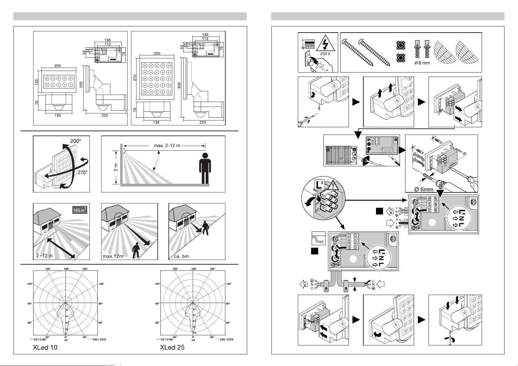
Installation –
Der Montageort sollte mindestens 50 cm von einer
anderen Leuchte entfernt sein, da Wärmestrahlung
zur Auslösung des Systems führen kann. Um die
angegebene Reichweite von max. 12 m zu erzielen,
sollte die Montagehöhe ca. 2 m betragen. Montieren
Sie das Gerät auf einen festen Untergrund, um Fehlschaltungen zu vermeiden.
Die Netzzuleitung besteht aus einem 3-adrigen Kabel:
- 7 -
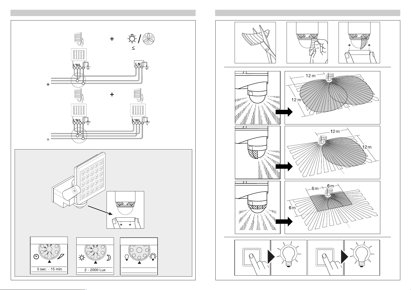
Funktionen
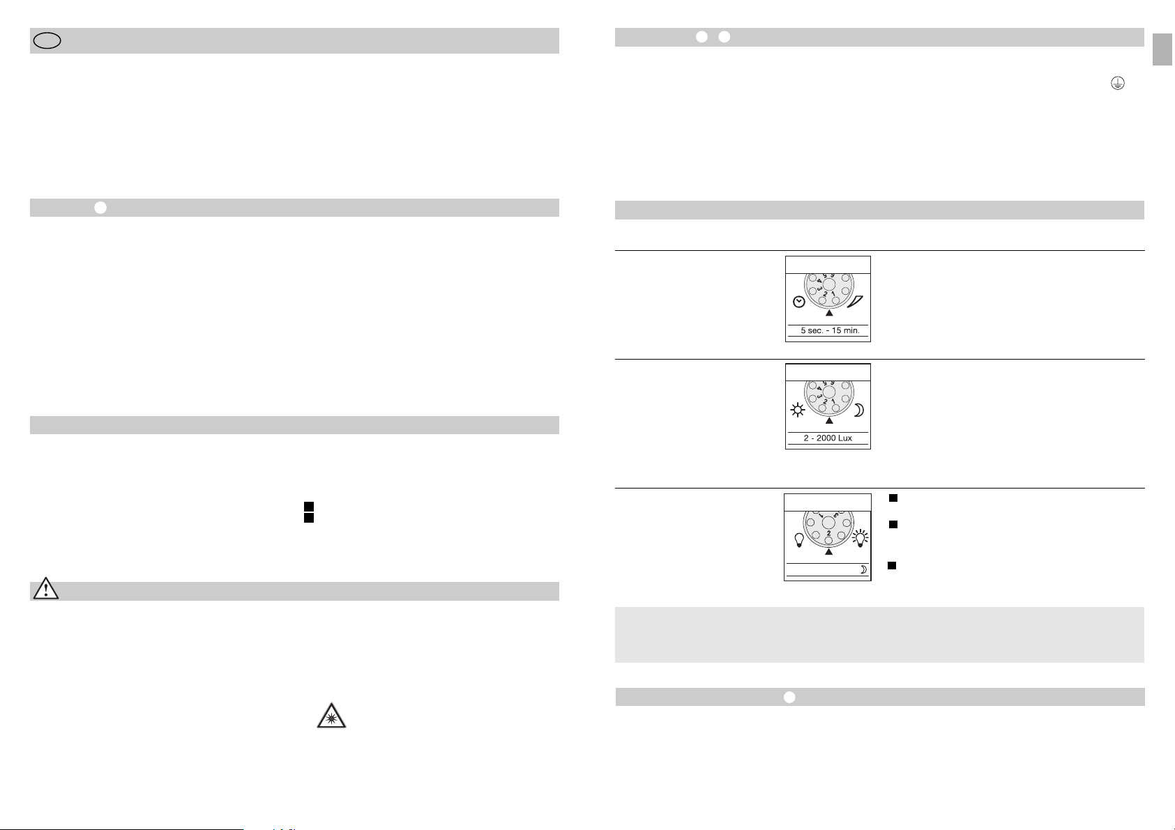
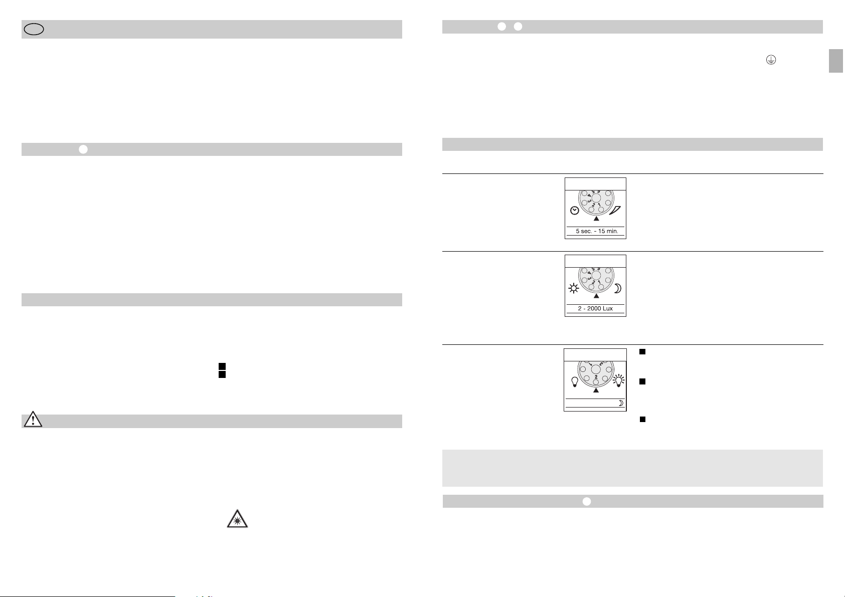
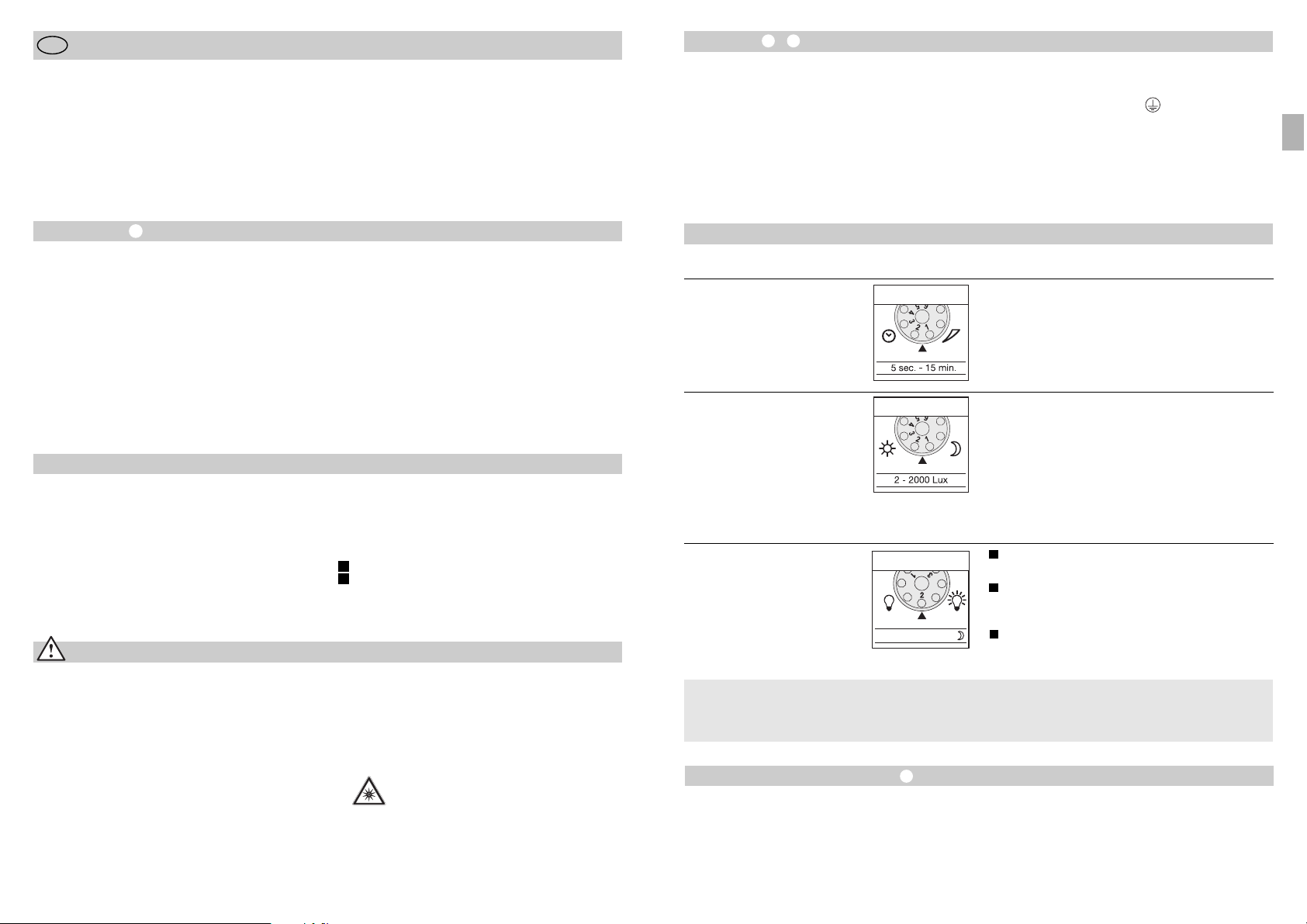
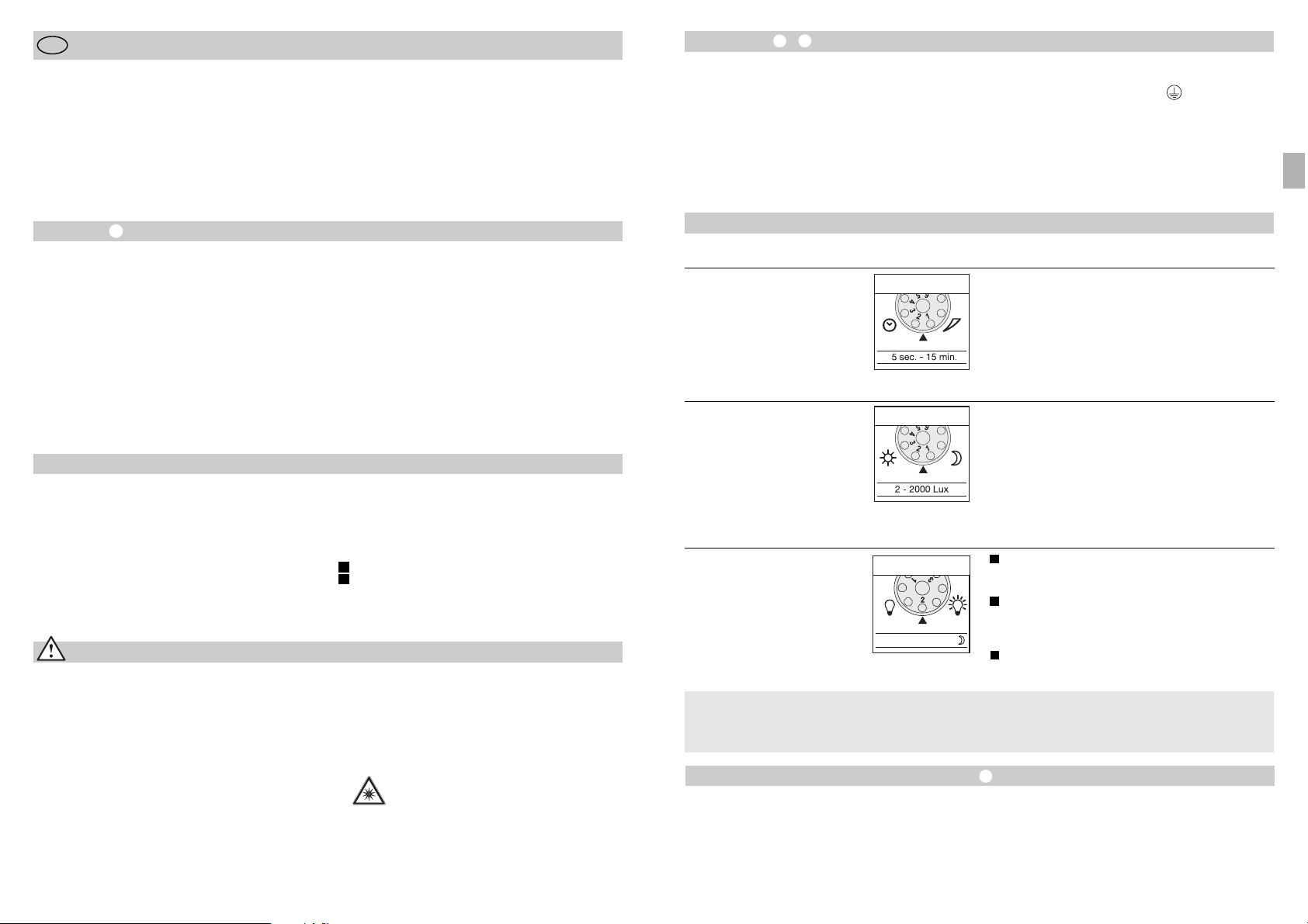
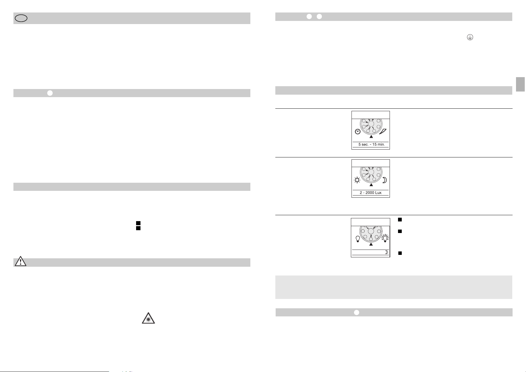
Ausschaltverzögerung
(Zeiteinstellung)
(Werkseinstellung: 5 Sek.)
Stufenlos einstellbare Leuchtdauer von 5 sek. –15 min.
Einstellreger auf 1 (Linksanschlag) gestellt =
kürzeste Zeit (5 Sek.)
Einstellreger auf 6 (Rechtsanschlag) gestellt =
längste Zeit (15 min.)
Bei Einstellung des Erfassungsbereiches wird
empfohlen die kürzeste Zeit 1 zu wählen.
Grundhelligkeit
(Werkseinstellung: Programm 1)
Strahler AN bei Bewegung ab eingestelltem
Dämmerungswert / keine Grundhelligkeit.
Strahler AN bei Bewegung ab eingestelltem
Dämmerungswert / + Grundhelligkeit (10%)
für 10 min. nach Ablauf der eingestellten Zeit.
Strahler AN bei Bewegung ab eingestelltem
Dämmerungswert / + Grundhelligkeit (10%)
die ganze Nacht
Dämmerungseinstellung
(Ansprechschwelle)
(Werkseinstellung:
Tageslichtbetrieb 2000 Lux)
Stufenlos einstellbare Ansprechschwelle des Sensors
von 2 – 2000 Lux.
Einstellregler auf 1 (Linksanschlag) gestellt =
Tageslichtbetrieb ca. 2000 Lux.
Einstellregler auf 6 (Rechtsanschlag) gestellt =
Dämmerungsbetrieb ca. 2 Lux.
Zur Einstellung des Erfassungsbereiches bei Tageslicht
ist der Einstellregler auf 1 (Tageslichtbetrieb) zu
stellen.
LED 10% OFF / 10 min. / ~
1
2
3
Alle Funktionen lassen sich bei abgezogener
Ringblende einstellen.
Was ist Grundhelligkeit ?
Grundhelligkeit ermöglicht eine Beleuchtung mit ca.
10 % Lichtleistung. Erst bei Bewegung im Erfassungsbereich wird das Licht (für die eingestellte Zeit,
s. Ausschaltverzögerung ) auf maximale Lichtleistung (100 %) geschaltet. Danach schaltet die
Leuchte für 10 Min. auf Grundhelligkeit (ca. 10 %).
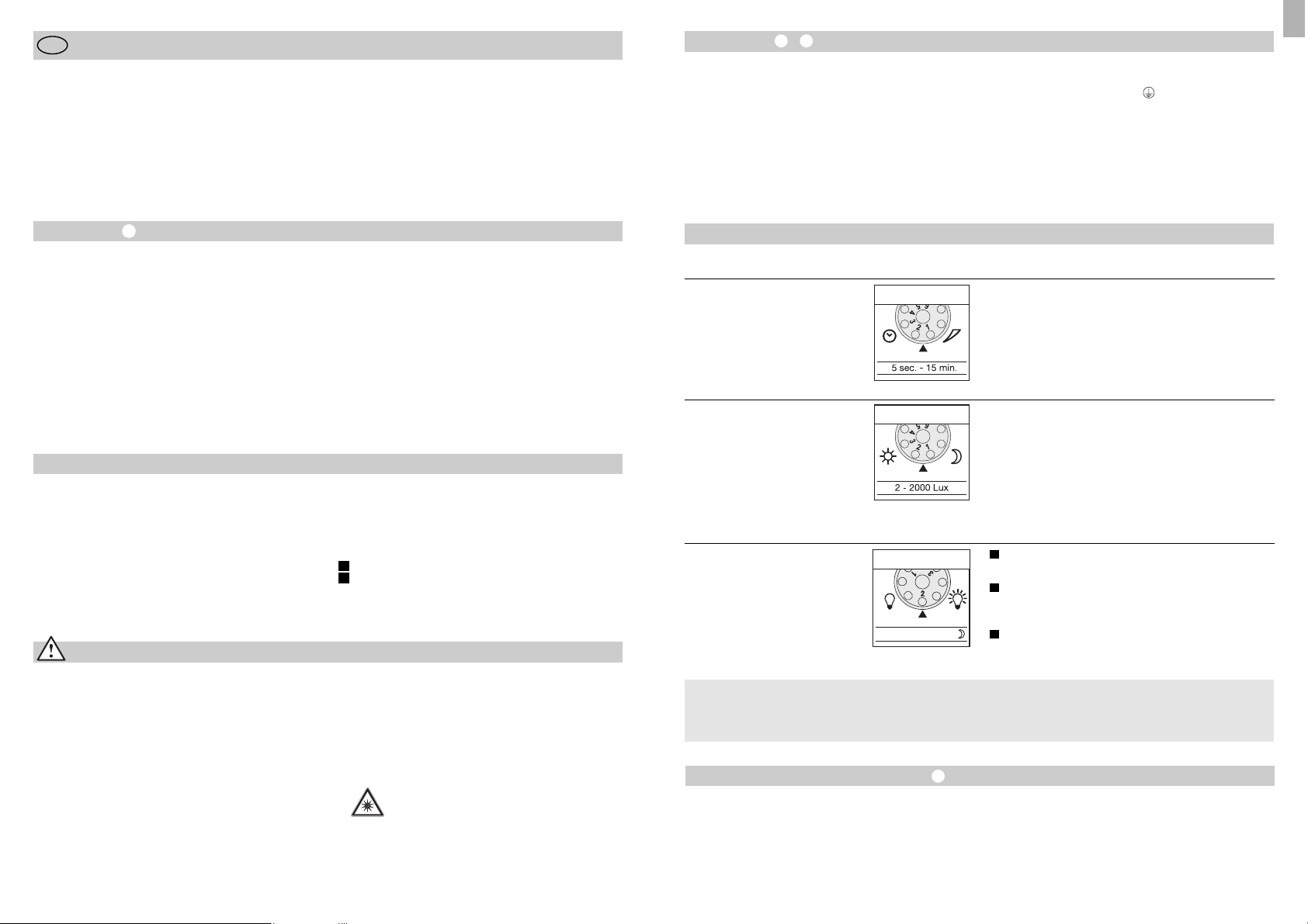
Reichweiteneinstellung/Justierung
Je nach Bedarf kann der Erfassungsbereich optimiert
werden. Die beiliegenden Abdeckblenden dienen
dazu, beliebig viele Linsensegmente abzudecken,
bzw. die Reichweite individuell zu verkürzen. Somit
werden Fehlschaltungen durch z. B. Autos, Passanten
etc. ausgeschlossen oder Gefahrenstellen gezielt
überwacht. Die Abdeckblenden können entlang der
vorgenuteten Einteilungen in der Senkrechten und
Waagerechten getrennt oder mit einer Schere
geschnitten werden. Nach Abziehen der Ringblende
sind diese im oberen Bereich der Sensorlinse einzuhängen. Die Ringblende ist danach wieder aufzustecken, wodurch die Abdeckblenden fest verankert
werden.
Durch Drehen des Sensorgehäuses um ± 80° ist
darüber hinaus eine Feinabstimmung möglich.
L = Phase (meistens schwarz oder braun)
N = Neutralleiter (meistens blau)
PE = Schutzleiter (grün/gelb)
Wichtig: Ein Vertauschen der Anschlüsse führt im
Ge rät oder Ihrem Siche rungs ka sten später zum Kurz schluss. In diesem Fall müssen die einzelnen Kabel
identifiziert und neu montiert werden. In die Netzzuleitung kann ein geeigneter Netz schalter zum EINund AUS-Schalten montiert sein.
- 6 -
Montageanleitung
Sehr geehrter Kunde,
vielen Dank für das Vertrauen, das Sie uns beim Kauf
Ihres neuen STEINEL-Sensor-LED-Strahlers entgegengebracht haben. Sie haben sich für ein hochwertiges Qualitätsprodukt entschieden, das mit größter Sorgfalt produziert, getestet und verpackt wurde.
Bitte machen Sie sich vor der Installation mit dieser
D
Sicherheitshinweise
■ Vor allen Arbeiten am Gerät die Spannungs zufuhr
unterbrechen!
■ Bei der Montage muss die anzuschließende
elektrische Leitung spannungsfrei sein. Daher als
Erstes Strom abschalten und Spannungsfreiheit
mit einem Spannungsprüfer überprüfen.
■ Bei der Installation dieser Geräte handelt es sich
um eine Arbeit an der Netz spannung; sie muss
da her fachgerecht nach den länderspezifischen
In stal lations vorschriften und Anschluß bedingungen
durchgeführt werden (D-VDE 0100,
A
-ÖVE/ÖNORM E 8001-1, -SEV 1000)
Montageanleitung vertraut. Denn nur eine sachgerechte Installation und Inbetriebnahme gewährleistet
einen langen, zuverlässigen und störungsfreien
Betrieb.
Wir wünschen Ihnen viel Freude an Ihrem neuen
STEINEL-Sensor-LED-Strahler.
■
Montieren Sie das Gerät nicht auf gewöhnlich leicht
entflammbaren Oberflächen.
■ Geeignet für Außen- und für Innenräume.
■ Der Sensor-LED-Strahler ist nur für die Wand-
montage und nicht für die Decken montage
vorgesehen.
■ Das Strahlergehäuse erwärmt sich während des
Betriebes. Die Ausrichtung des LED-Kopfes nur
durchführen, wenn dieser abgekühlt ist.
■ Nicht aus kurzer Distanz oder einen
längeren Zeitraum (> 5 min.) in die
LED-Leuchte blicken. Dies kann zu einer
Schädigung der Netzhaut führen.
Das Prinzip
Bewegung schaltet Licht, Alarm und vieles mehr. Für
Ihren Komfort, zu Ihrer Sicherheit. Sei es im privaten
Bereich zur Haus- und Grundstücksbeleuchtung oder
im gewerblichen Bereich z.B. zur Beleuchtung des
Firmengeländes, dieser Sensor-LED-Strahler ist überall schnell montiert und betriebsbereit.
Die Sensor-LED-Strahler XLed 10 und XLed 25 sind
mit zwei 120°-Pyro-Sensoren ausgestattet, die die
unsichtbare Wärmestrahlung von sich bewegenden
Körpern (Menschen, Tieren, etc.) erfassen. Diese so
erfaßte Wärmestrahlung wird elektronisch umgesetzt
und schaltet so den Strahler. Durch Hindernisse, wie
z.B. Mauern oder Glasscheiben, wird keine Wärmestrahlung erkannt. Mit Hilfe der zwei Pyro-Sensoren
wird ein Erfassungswinkel von 240° mit einem Öffnungswinkel von 180° erreicht.
Wichtig: Die sicherste Bewe gungserfassung haben
Sie, wenn Sie das Gerät seitlich zur Gehrichtung
montieren und keine Hindernisse (wie z.B. Bäu me,
Mauern etc.) die Sicht des Sensors behindern.
Gerätebeschreibung
LED-Kopf im Flat-Design
Gelenkarm
Kühlrippen
Wandhalter mit Netzteil
Sensoreinheit
Dichtstopfen
Abdeckschalen
Das Prinzip
Zeiteinstellung
Dämmerungseinstellung
Einstellung Grundhelligkeit
Reichweiteneinstellung/
Justierung des Erfassungsbereichs
Dauerlichtfuktion
Netzanschluss Zuleitung Unterputz
Netzanschluss Zuleitung Aufputz
I
II
D
Page 5
- 9 -
Funktionsgarantie
Dieses STEINEL-Produkt ist mit größter Sorgfalt
hergestellt, funktions- und sicherheitsgeprüft nach
geltenden Vorschriften und anschließend einer Stichprobenkontrolle unterzogen. STEINEL übernimmt die
Garantie für einwandfreie Beschaffenheit und Funktion.
Die Garantiefrist beträgt 36 Monate und beginnt mit
dem Tag des Verkaufs an den Verbraucher. Wir beseitigen Mängel, die auf Material- oder Fabrikationsfehlern beruhen, die Garantieleistung erfolgt durch
Instandsetzung oder Austausch mangelhafter Teile
nach unserer Wahl. Eine Garantieleistung entfällt für
Schäden an Verschleißteilen sowie für Schäden und
Mängel, die durch unsachgemäße Behandlung oder
Wartung auftreten. Weitergehende Folgeschäden an
fremden Gegenständen sind ausgeschlossen.
Die Garantie wird nur gewährt, wenn das unzerlegte
Gerät mit kurzer Fehlerbeschreibung, Kassenbon
oder Rechnung (Kaufdatum und Händlerstempel),
gut verpackt, an die zutreffende Servicestation eingesandt wird.
Reparaturservice:
Nach Ablauf der Garantiezeit oder
Mängeln ohne Garantieanspruch
repariert unser Werkservice. Bitte
das Produkt gut verpackt an die
nächste Servicestation senden.
Konformitätserklärung
Dieses Produkt erfüllt die Niederspannungrichtlinie
2006/95/EG, EMV-Richtlinie 2004/108/EG sowie
RoHS Richtlinie 2002/95/EG.
Betriebsstörungen
Sensor-LED-Strahler
ohne Spannung
Sensor-LED-Strahler
schaltet nicht ein
Sensor-LED-Strahler
schaltet nicht aus
Sensor-LED-Strahler
schaltet unerwünscht ein
Störung
■ Sicherung defekt, nicht eingeschaltet, Leitung unterbrochen
■ Kurzschluss
■ neue Sicherung, Netzschalter
einschalten; Leitung mit
Spannungsprüfer überprüfen
■ Anschlüsse überprüfen
■ bei Tagesbetrieb,
Dämmerungseinstellung
steht auf Nachtbetrieb
■ Netzschalter AUS
■ Sicherung defekt
■ Erfassungsbereich nicht
gezielt eingestellt
■ neu einstellen
■ Einschalten
■ neue Sicherung, evtl.
Anschluss überprüfen
■ neu justieren
■ dauernde Bewegung im
Erfassungsbereich
■ Bereich kontrollieren und
evtl. neu justieren bzw.
abdecken
■ Wind bewegt Bäume und
Sträucher im Erfassungsbereich
■ Erfassung von Autos auf
der Straße
■ plötzliche Temperaturveränderung durch Witterung (Wind,
Regen, Schnee) oder Abluft
aus Ventilatoren, offenen
Fenstern
■ Sensor-LED-Strahler
schwankt (bewegt sich) durch
z.B. Windböen oder starken
Niederschlag
■ Bereich umstellen
■ Bereich umstellen
■ Bereich verändern,
Montageort verlegen
■ Sensor-LED-Strahler auf
einen festen Untergrund
montieren
Ursache Abhilfe
Sensor-LED-Strahler
schaltet immer EIN/AUS
■ Tiere bewegen sich im
Erfassungsbereich
■ Sensor höher schwenken
bzw. gezielt abdecken;
Bereich umstellen, bzw.
abdecken
- 8 -
Betrieb und Pflege
Für spezielle Einbruchalarmanlagen ist das Gerät
nicht geeignet, da die hierfür vorgeschriebene Sabotagesicherheit fehlt. Witterungseinflüsse können die
Funktion der Sensor-LED-Strahler beeinflussen. Bei
starken Windböen, Schnee, Regen, Hagel kann es
zu einer Fehlschaltung kommen, da die plötzlichen
Temperaturschwankungen nicht von Wärmequellen
unterschieden werden können.
Die Erfassungslinse kann bei Verschmutzung mit
einem feuchten Tuch (ohne Reinigungsmittel)
gesäubert werden.
Dauerlichtfunktion
Wird ein Netzschalter in die Netzzuleitung montiert,
sind neben dem einfachen Ein- und Ausschalten
folgende Funktionen möglich:
Sensorbetrieb
1) Licht einschalten (wenn Strahler AUS):
Schalter 1 x AUS und AN.
LEDs bleiben für die eingestellte Zeit an.
2) Licht ausschalten (wenn Strahler AN):
Schalter 1 x AUS und AN.
Strahler geht aus bzw. in den Sensorbetrieb über.
Dauerlichtbetrieb
1) Dauerlicht einschalten:
Schalter 2 x AUS und AN. Der Strahler wird für
4 Stunden auf Dauerlicht gestellt (rote LED leuchtet
hinter der Linse). Anschließend geht sie automatisch
wieder in den Sensorbetrieb über (rote LED aus).
2) Dauerlicht ausschalten:
Schalter 1 x AUS und AN. Strahler geht aus bzw. in
den Sensorbetrieb über.
Wichtig:
Das mehrmalige Betätigen des Schalters sollte schnell
hintereinander erfolgen (im Bereich 0,5 – 1 Sek.).
D
Technische Daten
Sensor-LED-Strahler XLed 10 XLed 25
Leistung: 10 LEDs, ca. 25 W 25 LEDs, ca. 60 W
Lichtfarbe: ca. 4000 Kelvin (warmweiß) ca. 4000 Kelvin (warmweiß)
Lichtstrom: 960 Lumen 2120 Lumen
Zusätzliche Schaltleistung:
Glühlampen, max. 800 W bei 230 V AC
Leuchtstoffröhre, max. 400 W bei cos ϕ = 0,5,
induktive Last bei 230 V AC
Leuchtstofflampen, Energiesparlampen,
LED-Leuchten mit elektronischem Vorschaltgerät bei 230 V AC,
4 x max. je 60 W, C ≤ 88 μF
Lebensdauer LEDs: bis 50.000 Std. bis 50.000 Std.
(bei 3 Std./Tag ca. 45 Jahre) (bei 3 Std./Tag ca. 45 Jahre)
Erfassungswinkel: 240° mit Unterkriechschutz 240° mit Unterkriechschutz
Projezierte Fläche 250 cm2+ 103,36 cm
2
420 cm2+ 103,36 cm
2
Schwenkbereich
der Sensoreinheit: ± 80° ± 80°
Schwenkbereich Gehäuse: vertikal 200° vertikal 200°
horizontal 270° horizontal 270°
Zeiteinstellung: 5 Sek. – 15 Min. 5 Sek. – 15 Min.
Dämmerungseinstellung: 2 – 2000 Lux 2 – 2000 Lux
Helligkeitsregulierung: 10% Grundhelligkeit (ca. 3 W) 10% Grundhelligkeit (ca. 6 W)
Dauerlicht: 4 Std. einstellbar 4 Std. einstellbar
Abmessungen (H x B x T) 205 x 200 x 220 mm 300 x 200 x 220 mm
Gewicht: 2200 g 2960 g
Temperaturbereich: -20 °C bis +50 °C -20 °C bis +50 °C
Schutzart: IP 44 IP 44
Schutzklasse: I I
Page 6
Installation –
The site of installation should be at least 50 cm
away from another light because heat radiated from
it may activate the system. To obtain the specified
max. reach of 12 m, the sensor should be installed
at a height of approx. 2 m. Install the unit on a firm
surface to avoid unintentional triggering.
The mains supply lead is a 3-core cable.
- 11 -
Functions
Switch-off delay
(time setting)
(factory setting: 5 sec.)
Light "ON" duration can be infinitely varied from
5 sec. – 15 min.
Control dial set to 1 (turned fully anticlockwise) =
shortest time (5 sec.)
Control dial set to 6 (turned fully clockwise) =
longest (15 sec.)
To set the detection zone, it is recommended to
select the shortest time 1.
Basic brightness
(factory setting: programme 1)
Floodlight "ON" in response to movement from
twilight setting / no basic brightness.
Floodlight "ON" in response to movement from
twilight setting / + basic brightness (10%) for
10 min. after time set elapses.
Floodlight "ON" all night in response to movement
from twilight setting / + basic brightness (10%).
Twilight setting
(response threshold)
(factory setting:
daylight operation 2000 lux)
The sensor's response threshold can be infinitely
varied from 2 – 2000 lux.
Control dial set to number 1 (turned fully anticlockwise) = daylight operation (approx. 2000 lux).
Control dial set to 6 (turned fully clockwise) =
twilight operation (approx. 2 lux).
To adjust the detection zone in daylight, the control
dial must be set to 1 (daylight operation).
LED 10% OFF / 10 min. / ~
1
2
All functions can be set after removing the
decorative ring.
What is basic brightness?
Basic brightness provides illumination at approx.
10% light output. The light only switches to maximum output of 100% (for the time selected, see
Switch-off delay ) in response to movement in the
detection zone. The light then switches to basic
brightness for 10 min. (approx. 10%).
Reach Setting/Adjustment
The detection zone can be optimised to suit requirements. The shrouds provided are used for blanking
out any number of lens segments or to shorten reach
as required. This prevents the light from being activated unintentionally, e.g. by cars, passers-by etc., and
allows you to target danger spots. The shrouds can
be divided or cut with a pair of scissors along the
vertical and horizontal grooves. After removing the
decorative ring, the shrouds can be clipped on at the
top of the sensor lens. The decorative ring must now
be pushed back on to hold the shrouds firmly in place.
You can turn the sensor housing through ± 80°
for precision adjustment.
L = phase conductor (usually black or brown)
N = neutral conductor (usually blue)
PE = protective-earth conductor (green/yellow)
Important: Connecting the conductors to the wrong
terminals will produce a short circuit in the unit or
your fuse box at a later stage when you come to
switch the power on. In this case, you must identify
the individual cables and re-connect them. A suitable
mains switch for switching the light "ON" and "OFF"
can be installed in the mains lead.
- 10 -
Installation Instructions
Dear Customer,
Congratulations on purchasing your new STEINEL
sensor-switched LED floodlight and thank you for the
confidence you have shown in us. You have chosen
a high-quality product that has been manufactured,
tested and packed with the greatest care.
GB
Safety Warnings
■ Disconnect the power supply before attempting
any work on the unit.
■ During installation, the electrical wiring you are
connecting must be dead. Therefore, switch off the
power first and use a voltage tester to check that
the power supply is disconnected.
■ Installing these lights involves work on the mains
voltage supply; This work must therefore be carried
out professionally in accordance with applicable
national wiring regulations and electrical operating
conditions (D-VDE 0100, A-ÖVE/ÖNORM E
8001-1, -SEV 1000)
Please familiarise yourself with these instructions
before attempting to install the light because prolonged, reliable and trouble-free operation will only
be ensured if it is installed and used properly.
We hope your new STEINEL sensor-switched LED
floodlight will bring you lasting pleasure.
■ Do not install the unit on normally flammable
surfaces.
■ Suitable for outdoor and indoor use.
■ The sensor-switched LED floodlight is only intended
for wall mounting and not for ceiling mounting.
■ The floodlight housing gets warm while it is
switched "ON". Only adjust the angle of the LED
head once it has cooled down.
■ Do not look into the LED light at short
range or for any prolonged period
(> 5 min.). You could damage your retina.
Principle
Movement triggers lights, alarms and many other
devices - for your convenience and safety. Whether
at home, to illuminate your property, or commercially,
e.g. to light up business premises, this sensorswitched LED floodlight is quickly installed and ready
for use.
Sensor-switched LED floodlights XLed 10 and XLed
25 are equipped with two 120° pyro sensors which
detect the invisible heat emitted by moving objects
(people, animals etc.). The heat detected in this way
is converted electronically into a signal that switches
the floodlight "ON". Heat is not detected through
obstacles, such as walls or panes of glass. The two
pyro sensors achieve a coverage angle of 240° with
an aperture angle of 180°.
Important: The most reliable way of detecting movement is to install the unit with the sensor aimed
across the direction in which a person would walk
and by ensuring that no obstacles (such as trees,
walls etc.) obstruct the line of sensor vision.
System Components
LED head in flat design
Pivoted arm
Cooling fins
Wall mount with power supply unit
Sensor unit
Sealing plugs
Shrouds
Principle
Time setting
Twilight setting
Basic brightness setting
Reach setting/adjustment of detection angle
Manual override function
Mains connection, concealed wiring
Mains connection, surface wiring
I
II
GB
3
Page 7

- 13 -
Functional warranty
This STEINEL product has been manufactured with
utmost care, tested for proper operation and safety
and then subjected to random sample inspection.
STEINEL guarantees that it is in perfect condition
and proper working order.
The warranty period is 36 months and starts on the
date of sale to the consumer. We will remedy defects
caused by material flaws or manufacturing faults.
The warranty will be met by repair or replacement of
defective parts at our own discretion. The warranty
shall not cover damage to wear parts, damage or
defects caused by improper treatment or maintenance. Further consequential damage to other objects
is excluded.
Claims under the warranty will only be accepted if the
unit is sent fully assembled and well-packed with a
brief description of the fault, a receipt or invoice (date
of purchase and dealer's stamp) to the appropriate
Service Centre.
Repair service:
Our Customer Service Department
will repair faults not covered by warranty or after the warranty period.
Please send the product well packed
to your nearest Service Centre.
Declaration of conformity
This product complies with Low Voltage Directive
2006/95/EC, EMC Directive 2004/108/EC as well as
RoHS Directive 2002/95/EC.
Troubleshooting
Sensor-switched LED floodlight
without power
Sensor-switched LED floodlight
will not switch "ON"
Sensor-switched LED floodlight
will not switch "OFF"
Sensor-switched LED floodlight
switches "ON" when it should not
Malfunction
■ Fuse faulty, not switched "ON",
break in wiring
■ Short circuit
■ Fit new fuse; switch "ON"
mains switch; check wiring
with voltage tester
■ Check connections
■ Twilight control set to night-time
mode during daytime operation
■ Mains power switch "OFF"
■ Fuse faulty
■ Detection zone not properly
targeted
■ Adjust setting
■ Switch "ON"
■ Fit new fuse, check connection
if necessary
■ Re-adjust
■ Continuous movement in the
detection zone
■ Check zone and readjust if
necessary or apply shroud
■ Wind is moving trees and
bushes in the detection zone
■ Cars in the street are being
detected
■ Sudden temperature changes
due to weather (wind, rain,
snow) or air expelled from fans,
open windows
■ Sensor-switched LED floodlight
is moving (swaying) due to gusts
of wind or heavy rain.
■ Change detection zone
■ Change detection zone
■ Adjust detection zone or install
in a different place
■ Mount sensor-switched LED
floodlight on a firm surface
Cause Remedy
Sensor-switched LED floodlight
keeps switching "ON" and "OFF"
■ Animals moving in the
detection zone
■ Tilt sensor higher or apply
specific shrouds; adjust zone,
or apply shrouds
- 12 -
Operation and Maintenance
The unit is not suitable for special burglary alarm
systems since it lacks the tampering protection prescribed for this purpose. Weather can affect operation
of the sensor-switched LED floodlight. Strong gusts
of wind, snow, rain and hail may cause the light to
come "ON" when it is not wanted because the sensor is
unable to distinguish sudden changes in temperature
from sources of heat.
The detector lens may be cleaned with a damp cloth
if it gets dirty (do not use cleaning agents).
Permanent Light Function
If a mains switch is installed in the mains supply lead,
the light is capable of the following functions in addition to the simple "ON"/"OFF" function:
Sensor operation
1) Switch light "ON" (when floodlight is "OFF"):
Switch "OFF" and "ON" once.
LEDs stay "ON" for the period selected.
2) Switch light "OFF" (when floodlight is "ON"):
Switch "OFF" and "ON" once.
Floodlight goes out or switches to sensor mode.
Manual override
1) Activate manual override:
Turn switch "OFF" and "ON" twice. The floodlight is
set to stay "ON" for 4 hours (red LED lights up behind
the lens). Then it returns automatically to sensor
mode (red LED "OFF").
2) Deactivate manual override:
Switch "OFF" and "ON" once. Floodlight goes out or
switches to sensor mode.
Important:
The switch should be actuated in rapid succession
(in the 0.5 – 1 sec. range).
Technical specifications
Sensor-switched LED floodlight XLed 10 XLed 25
Wattage: 10 LED’s, approx. 25 W 25 LED’s, approx. 60 W
Light colour: approx. 4000 kelvin (warm white) approx. 4000 kelvin (warm white)
Luminous flux: 960 lumens 2120 lumens
Additional switching capacity:
Filament bulbs, 800 W max. at 230 V AC
Fluorescent tube, 400 W max. at cos ϕ = 0.5,
inductive load at 230 V AC
Fluorescent lamps, low-energy lamps,
LED lights with electronic ballast at 230 V AC,
4 x 60 W each max., C ≤ 88 µF
Life of LED’s: up to 50,000 hrs. up to 50,000 hrs.
(for 3 hrs./day approx. 45 years) (for 3 hrs./day approx. 45 years)
Angle of coverage: 240° with sneak-by guard 240° with sneak-by guard
Projected area 250 cm2+ 103.36 cm
2
420 cm2+ 103.36 cm
2
Swivelling range of
sensor unit: ± 80° ± 80°
Swivelling range of housing: 200° vertically 200° vertically
270° horizontally 270° horizontally
Time setting: 5 sec. – 15 min. 5 sec. – 15 min.
Twilight setting: 2 – 2000 lux 2 – 2000 lux
Brightness control: 10% basic brightness (approx. 3 W) 10% basic brightness (approx. 6 W)
Permanent light "ON": 4 hrs., selectable 4 hrs., selectable
Dimensions (h x w x d) 205 x 200 x 220 mm 300 x 200 x 220 mm
Weight: 2200 g 2960 g
Temperature range: -20 °C to + 50 °C -20 °C to +50 °C
IP rating: IP 44 IP 44
Protection class: I I
GB
Page 8
Installation –
Il faut monter l'appareil à une distance d'au moins
50 cm de toute lampe car la chaleur pourrait entraî-
ner un déclenchement intempestif du détecteur. Pour
obtenir la portée indiquée de 12 m max., la hauteur
d'installation doit être d'environ 2 m. Pour éviter les
déclenchements intempestifs, installer l'appareil sur
un support solide.
La conduite secteur est composée d'un câble à
3 conducteurs :
- 15 -
Fonctionnement
Temporisation de l'extinction
(Minuterie)
(réglage effectué en usine : 5 s)
Durée d'éclairage réglable en continu de 5 s à 15 min.
Bouton de réglage sur le chiffre 1 (butée à gauche) =
temps le plus court (5 s)
Bouton de réglage sur le chiffre 6 (butée à droite) =
temps le plus long (15 min)
Pour le réglage de la zone de détection il est recommandé de sélectionner le temps le plus court 1.
Luminosité de base
(réglage effectué en usine :
programme 1)
Projecteur MARCHE en cas de mouvement à
partir de la valeur de crépuscularité sélectionnée /
pas de luminosité de base.
Projecteur MARCHE en cas de mouvement à
partir de la valeur de crépuscularité sélectionnée /
+ luminosité de base (10%) pour 10 min après
écoulement du temps programmé.
Projecteur MARCHE en cas de mouvement à
partir de la valeur de crépuscularité sélectionnée /
+ luminosité de base (10%) pendant toute la nuit.
Réglage de crépuscularité
(Seuil de réaction)
(réglage effectué en usine :
fonctionnement diurne 2 000 lux)
Seuil de réaction du détecteur réglable en continu de
2 – 2 000 lux.
Bouton de réglage sur le chiffre 1 (butée à gauche) =
fonctionnement diurne env. 2000 lux.
Bouton de réglage sur le chiffre 6 (butée à droite) =
fonctionnement nocturne env. 2 lux.
Pour régler la zone de détection à la lumière du jour,
il faut placer le bouton de réglage sur le chiffre 1
(fonctionnement diurne).
LED 10% OFF / 10 min. / ~
1
2
Toutes les fonctions peuvent être réglées lorsque
l'anneau de protection est retiré.
Qu'est-ce que la luminosité de base ?
La luminosité de base permet un éclairage avec
une puissance d'environ 10 %. La pleine puissance
s’enclenche pour la durée programmée lorsqu’un
mouvement est détecté. La lampe commute ensuite
à nouveau sur luminosité de base pour 10 min
(env. 10 %).
Réglage de la portée/ajustage
La zone de détection peut être optimisée en fonction
des besoins. Les caches enfichables fournis servent à
recouvrir autant de segments de lentille que l'on désire, ou bien à limiter individuellement la portée. Ceci
permet d'éviter les déclenchements intempestifs provoqués par ex. par des voitures, des passants, etc.
ou de cibler la surveillance des sources de danger.
Les caches enfichables pré-rainurés sont sécables
horizontalement ou verticalement ou peuvent être
coupés avec des ciseaux. Pour les mettre en place,
retirer l’anneau de protection de la lentille, positionner
les caches puis replacer l’anneau de protection pour
les fixer.
En faisant pivoter le boîtier du détecteur de ± 80° il
est en outre possible d'effectuer un réglage fin.
L = phase (généralement noir ou marron)
N = neutre (généralement bleu)
PE = conducteur de terre (vert/jaune)
Important : Une inversion des branchements entraîne
un court-circuit dans l’appareil ou dans le boîtier à
fusibles. Dans ce cas, il faut à nouveau identifier les
câbles et les raccorder en conséquence. Il est possible de monter sur la conduite secteur un interrupteur adéquat permettant la mise en ou hors circuit de
l'appareil.
- 14 -
Instructions de montage
Cher client,
Nous vous remercions de la confiance que vous avez
témoignée à STEINEL en achetant ce projecteur LED
à détecteur. Vous avez choisi un article de très grande
qualité, fabriqué, testé et conditionné avec le plus
grand soin.
F
Consignes de sécurité
■ Avant toute intervention sur l'appareil,
couper l'alimentation électrique !
■ Pendant le montage, les conducteurs à raccorder
doivent être hors tension. Il faut donc d'abord
couper le courant et s'assurer de l'absence de
courant à l'aide d'un testeur de tension.
■ L'installation de ces appareils implique une intervention sur le réseau ; elle doit donc être effectuée
par un professionnel conformément aux prescriptions de montage et conditions de raccordement
spécifiques au pays (F) -NF C-15100)
Avant de l’installer, veuillez lire attentivement ces instructions de montage. En effet, seules une installation
et une mise en service correctement effectuées
garantissent durablement un fonctionnement impeccable et fiable.
Nous souhaitons que votre nouveau projecteur LED à
détecteur STEINEL vous apporte entière satisfaction.
■ N'installez pas l'appareil sur des surfaces facilement inflammables.
■ Pour utilisation à l'extérieur et à intérieur.
■ Les projecteurs LED à détecteur sont conçus
uniquement pour le montage mural et non pour
le montage au plafond.
■ Quand le projecteur fonctionne, le boîtier est
brûlant. Laisser refroidir la tête LED avant de
l'orienter.
■ Ne pas regarder la lampe LED de près ou
de façon prolongée (> 5 mn.). Cela pourrait
endommager la rétine.
Le principe
Pour votre confort et votre sécurité, le mouvement
déclenche lumière, alarme, etc. Que ce soit pour
éclairer votre maison ou votre terrain, ou pour un
usage commercial, par ex. pour éclairer le site de
l'entreprise, ces projecteurs LED à détecteur s'installent rapidement partout et sont prêts à fonctionner.
Les projecteurs LED à détecteur XLed 10 et XLed 25
sont munis de deux détecteurs pyroélectriques de
120° qui détectent la chaleur corporelle des corps en
mouvement (personnes, animaux, etc.). Ce rayonnement de chaleur est traité par un système électro-
nique qui commande le projecteur. Les obstacles
comme les murs ou les vitres s'opposent à la détection du rayonnement de chaleur. Les deux détecteurs
pyroélectriques couvrent un angle de détection de
240° avec une ouverture angulaire de 180°.
Important : La détection des mouvements est la plus
fiable quand l'appareil est monté perpendiculairement
au sens de passage et qu'aucun obstacle (arbre, mur,
etc.) n'obstrue le champ de visée du détecteur.
Description de l’appareil
Tête LED design plat
Bras articulé
Ailettes de refroidissement
Support mural avec bloc secteur
Unité de détecteur
Joint d'étanchéité
Bouchons
Le principe
Minuterie réglable
Réglage de crépuscularité
Réglage luminosité de base
Réglage de la portée/ajustage de la zone
de détection
Fonction éclairage permanent
Raccordement au secteur conduite sous crépi
Raccordement au secteur conduite sur crépi
I
II
F
3
Page 9
- 17 -
Service après-vente et garantie
Ce produit Steinel a été fabriqué avec le plus grand
soin. Son fonctionnement et sa sécurité ont été
contrôlés conformément aux directives en vigueur et
il a été soumis à un contrôle final par sondage.
STEINEL garantit un état et un fonctionnement
irréprochables.
La durée de garantie est de 36 mois et débute le jour
de la vente au consommateur. Nous remédions aux
défauts provenant d'un vice de matière ou de fabrication. La garantie sera assurée à notre discrétion par
réparation ou échange des pièces défectueuses. La
garantie ne s’applique ni aux pièces d’usure, ni aux
dommages et défauts dus à une utilisation ou maintenance incorrectes. Les dommages consécutifs causés à d'autres objets sont exclus de la garantie.
La garantie ne s'applique que si l'appareil non
démonté est retourné au point de service après-vente
le plus proche, dans un emballage adéquat, accompagné de la description brève de la panne et d'un
ticket de caisse ou d'une facture portant la date
d'achat et le cachet du vendeur.
Service de réparation :
Le service après-vente de notre usine
effectue également les réparations
non couvertes par la garantie ou survenant après l'expiration de celle-ci.
Veuillez envoyer le produit correctement emballé à la station de service après-vente
la plus proche.
Déclaration de conformité
Ce produit est conforme à la directive basse tension
2006/95/CE, à la directive compatibilité électromagnétique 2004/108/CE et à la directive
RoHS 2002/95/CE.
Dysfonctionnements
Projecteur LED à détecteur
sans tension
Projecteur LED à détecteur
ne s'allume pas
Projecteur LED à détecteur ne
s'éteint pas
Projecteur LED à détecteur
s'allume involontairement
Problème
■ Fusible défectueux, appareil
hors circuit, câble coupé
■ Court-circuit
■ Changer le fusible défectueux,
mettre l'interrupteur en circuit ;
vérifier le câble à l'aide d'un
testeur de tension
■ Vérifier le branchement
■ En fonctionnement diurne,
le réglage de crépuscularité est
positionné sur fonctionnement
nocturne
■ Interrupteur en position ARRÊT
■ Fusible défectueux
■ Réglage incorrect de la zone
de détection
■ Ajuster à nouveau
■ Mettre en circuit
■ Changer le fusible, éventuelle-
ment vérifier le branchement
■ Ajuster à nouveau
■ Mouvement continu dans la
zone de détection
■ Contrôler la zone de détection,
éventuellement la régler à nouveau ou la masquer
■ Le vent agite des arbres et
des arbustes dans la zone de
détection
■ Détection de voitures passant
sur la chaussée
■ Variations subites de température dues aux intempéries (vent,
pluie, neige) ou à des courants
d'air provenant de ventilateurs
ou de fenêtres ouvertes
■ Le projecteur LED à détecteur
oscille (remue) à cause par ex.
de rafales de vent ou de fortes
précipitations.
■ Modifier la zone
■ Modifier la zone
■ Modifier la zone, monter
l'appareil à un autre endroit
■ Installer le projecteur LED à
détecteur sur un support solide
Cause Remède
Le projecteur LED à détecteur
s'allume et s'éteint continuellement
■ Des animaux se déplacent dans
la zone de détection
■ Orienter le détecteur plus vers
le haut ou réduire la zone ;
modifier ou réduire la zone
- 16 -
Utilisation et entretien
Le projecteur n’étant pas protégé contre le vandalisme, il ne convient pas de l’utiliser comme système
anti-intrusion. Les conditions atmosphériques peuvent influencer le fonctionnement du projecteur à
détecteur. Les rafales de vent, la neige, la pluie, la
grêle peuvent entraîner un déclenchement intempestif
car le détecteur ne peut pas distinguer les brusques
variations de température des sources de chaleur.
Si la lentille se salit, on la nettoiera avec un chiffon
humide (ne pas utiliser de détergent).
Fonction éclairage permanent
Si un interrupteur est installé sur la conduite secteur,
en plus de l'allumage et de l'extinction, on dispose
des fonctions suivantes :
Fonctionnement avec détecteur
1) Allumer la lumière (si le projecteur est sur
ARRÊT) :
Actionner l'interrupteur 1 x ARRÊT/MARCHE.
Les LED restent allumées pendant la durée réglée.
2) Éteindre la lumière (si le projecteur est sur
MARCHE) :
Actionner l'interrupteur 1 x ARRÊT/MARCHE.
Le projecteur s'éteint ou repasse en mode détection.
Éclairage permanent
1) Allumer l'éclairage permanent :
Actionner l’interrupteur 2 x ARRÊT/MARCHE. Le
projecteur est mis en éclairage permanent pendant
4 heures (la LED rouge derrière la lentille clignote).
Elle repasse ensuite automatiquement en mode
détection (LED rouge éteinte).
2) Éteindre l'éclairage permanent :
Actionner l'interrupteur 1 x ARRÊT/MARCHE. Le
projecteur s'éteint ou repasse en mode détection.
Important :
Il faut actionner l'interrupteur rapidement en suivant
(en l'espace de 0,5 à 1 s).
Caractéristiques techniques
Projecteur LED à détecteur XLed 10 XLed 25
Puissance : 10 LED, env. 25 W 25 LED, env. 60 W
Couleur de la lumière : 4000 kelvin env. (blanc chaud) 4000 kelvin env. (blanc chaud)
Flux lumineux : 960 lumen 2120 lumen
Puissance d’éclairage supplémentaire :
Lampes à incandescence, 800 W max. pour 230 V AC
Tube fluorescent, 400 W max. pour cos ϕ = 0,5,
charge inductive pour 230 V CA
Tubes fluorescents, lampes à économie d’énergie,
lampes LED avec ballast électronique pour 230 V CA,
4 x 60 W max. chacune, C ≤ 88 µF
Durée de vie des LED : jusqu'à 50.000 h. jusqu'à 50.000 h.
(pour 3 heures/jour, env. 45 ans) (pour 3 heures/jour, env. 45 ans)
Angle de détection : 240° avec protection au ras du mur 240° avec protection au ras du mur
Surface projetée 250 cm2+ 103,36 cm
2
420 cm2+ 103,36 cm
2
Orientabilité
de l'unité de détecteur : ± 80° ± 80°
Orientabilité du boîtier : verticalement 200° verticalement 200°
horizontalement 270° horizontalement 270°
Temporisation : 5 s – 15 min 5 s – 15 min
Réglage de crépuscularité : 2 – 2000 lux 2 – 2000 lux
Réglage de l'intensité de veille : 10% luminosité de base (env. 3 W) 10% luminosité de base (env. 6 W)
Eclairage permanent : 4 h. réglable 4 h. réglable
Dimensions (H x l x P) : 205 x 200 x 220 mm 300 x 200 x 220 mm
Poids : 2200 g 2960 g
Variation de température : -20 °C à +50 °C -20 °C à +50 °C
Indice de protection : IP 44 IP 44
Classe : I I
F
Page 10
Installatie –
De montageplaats dient minimaal 50 cm van een
andere lamp verwijderd te zijn, omdat de warmte-
straling het systeem kan activeren. Om de aangegeven reikwijdte van max. 12 m te bereiken, mag de
montagehoogte ca. 2 m zijn. Monteer het apparaat
op een vaste ondergrond om foutieve schakelingen
te voorkomen.
De stroomtoevoer bestaat uit een 3-polige kabel:
- 19 -
Functies
Uitschakelvertraging
(tijdinstelling)
(instelling af fabriek: 5 sec.)
Traploos instelbare brandduur van 5 sec. – 15 min.
Instelknopje op 1 (linkeraanslag) = kortste tijd (5 sec.)
Instelknopje op 6 (rechteraanslag) = langste tijd (15 min.)
Bij de instelling van het registratiebereik wordt geadviseerd om de kortste tijd 1 te kiezen.
Basislichtsterkte
(instelling af fabriek: programma 1)
Lamp AAN bij beweging vanaf de ingestelde
schemerwaarde / geen basislichtsterkte.
Lamp AAN bij beweging vanaf de ingestelde
schemerwaarde / + basislichtsterkte (10%)
voor 10 min. na afloop van de ingestelde tijd.
Lamp AAN bij beweging vanaf een ingestelde
schemerwaarde / + basislichtsterkte (10%)
de hele nacht.
Schemerinstelling
(drempelwaarde)
(instelling af fabriek:
daglichtstand 2000 lux)
Traploos instelbare drempelwaarde van de sensor
van 2 – 2000 lux.
Instelknopje op 1 (linkeraanslag) = daglichtstand
ca. 2000 lux.
Instelknopje op 6 (rechteraanslag) = schemerstand
ca. 2 lux.
Voor de instelling van het registratiebereik bij daglicht
moet het instelknopje op 1 (daglichtstand) worden
gezet.
LED 10% OFF / 10 min. / ~
1
2
Alle functies kunnen worden ingesteld wanneer de
bevestigingsring verwijderd is.
Wat is basislichtsterkte?
Basislichtsterkte maakt een verlichting met ca. 10 %
lichtvermogen mogelijk. Pas bij beweging in het
registratiebereik wordt het licht (voor de ingestelde
tijd, zie uitschakelvertraging ) naar het maximale
lichtvermogen (100 %) geschakeld. Daarna schakelt
de lamp voor 10 minuten weer terug naar de basislichtsterkte (ca. 10 %).
Reikwijdte-instelling/afstelling
Het registratiebereik kan indien gewenst beperkt worden. Met de meegeleverde afdekplaatjes kunnen willekeurig veel lenssegmenten worden afgedekt, resp.
de reikwijdte kan individueel worden verkort. Hierdoor
worden verkeerde schakelingen door bijv. auto's,
voetgangers etc. voorkomen of bepaalde gebieden
gericht bewaakt. De afdekplaatjes kunnen langs de
inkepingen verticaal en horizontaal worden afgebro-
ken of met een schaar worden doorgeknipt. Na het
verwijderen van de bevestigingsring kunnen deze
boven in de sensorlens worden gehangen. De bevestigingsring daarna weer vastdraaien, zodat de afdekplaatjes vast verankerd worden.
Door het sensorhuis ± 80° te draaien, is bovendien
een fijnafstelling mogelijk.
L = fase (in Nederland meestal bruin in
Belgie meestal zwart)
N = nuldraad (meestal blauw)
PE = aardedraad (groen/geel)
Belangrijk: Het verwisselen van de aansluitingen leidt
in het apparaat of de meterkast later tot kortsluiting.
In dit geval moeten de afzonderlijke kabels geïdentificeerd en opnieuw aangesloten worden. In de stroomtoevoerkabel kan een geschikte netschakelaar voor
IN- en UIT-schakelen worden gemonteerd.
- 18 -
Gebruiksaanwijzing
Geachte klant,
Hartelijk dank voor het vertrouwen dat u met de aanschaf van uw nieuwe sensor-LED-spot van STEINEL
in ons heeft gesteld. U heeft een modern kwaliteitsproduct gekocht, dat met uiterste zorgvuldigheid vervaardigd, getest en verpakt werd.
NL
Veiligheidsvoorschriften
■ Voordat u werkzaamheden aan het apparaat uitvoert altijd eerst de stroomtoevoer onderbreken!
■ Bij de montage moet de aan te sluiten elektrische
kabel spanningsvrij zijn. Daarom eerst de stroom
uitschakelen en op spanningsloosheid testen met
een spanningstester.
■ Bij de installatie van de lamp werkt u met netspanning. Dit moet vakkundig en volgens de gebruikelijke installatievoorschriften en aansluitingsvoorwaarden worden uitgevoerd (NL: NEN 1010).
Lees voor de installatie deze gebruiksaanwijzing
nauwkeurig door, want alleen een vakkundige installatie en ingebruikneming garanderen een duurzaam,
betrouwbaar en storingvrij gebruik.
Wij wensen u veel plezier met uw nieuwe sensorLED-spot van STEINEL.
■ Monteer het apparaat niet op normaal licht
ontvlambare oppervlakken.
■ Geschikt voor buiten en binnen.
■ De sensor-LED-spot is alleen geschikt voor wand-
montage en niet voor montage aan het plafond.
■ De behuizing van de lamp warmt op tijdens het
gebruik. Verander de positie van de LED-kop alleen
als die helemaal is afgekoeld.
■ Niet van dichtbij of gedurende langere tijd
(> 5 min.) in de LED-lamp kijken. Dit kan
tot beschadiging van het netvlies leiden.
Het principe
Beweging schakelt licht, alarm en veel meer aan.
Voor uw gemak en uw veiligheid. Geschikt voor particulier gebruik om huis en tuin te verlichten of voor
commercieel gebruik bijv. voor het verlichten van het
bedrijfsterrein, deze sensor-LED-spot is overal snel
gemonteerd en bedrijfsklaar.
De sensor-LED-spots XLed 10 en XLed 25 zijn voorzien van twee 120°-pyro-sensoren, die de onzichtbare
warmtestraling van bewegende mensen, dieren enz.
registreren. Deze zo geregistreerde warmtestraling
wordt elektronisch omgezet en schakelt hierdoor de
lamp automatisch aan. Door hindernissen zoals
muren of ruiten wordt geen warmtestraling herkend
en er volgt dan ook geen schakeling. Met behulp van
de twee pyro-sensoren wordt een registratiehoek van
240° met een openingshoek van 180° bereikt.
Belangrijk: De beste bewegingsregistratie heeft u als
het apparaat zijdelings in de looprichting wordt
gemonteerd en geen hindernissen (zoals bomen,
muren enz.) het zicht van de sensor belemmeren.
Beschrijving van het apparaat
LED-kop in plat design
Scharnierarm
Koelgleuf
Wandhouder met voedingsgedeelte
Sensorunit
Afdichtingsdopje
Afdekplaatjes
Het principe
Tijdinstelling
Schemerinstelling
Instelling basislichtsterkte
Reikwijdte-instelling/afstelling van het
registratiebereik
Permanente verlichting
Netaansluiting leidingen in de muur
Netaansluiting leidingen op de muur
I
II
NL
3
Page 11
- 21 -
Functiegarantie
Dit STEINEL-product is met grote zorgvuldigheid
gefabriceerd, getest op goede werking en veiligheid
volgens de geldende voorschriften, en vervolgens
steekproefsgewijs gecontroleerd. STEINEL verleent
garantie op de storingvrije werking.
De garantietermijn bedraagt 36 maanden en gaat in
op de datum van aanschaf door de klant. Alle klachten, die berusten op materiaal- of fabricagefouten,
worden door ons opgelost. De garantie bestaat uit
reparatie of vernieuwen van de defecte onderdelen,
door ons te beoordelen. Garantie vervalt bij schade
aan onderdelen, die aan slijtage onderhevig zijn en bij
schade of gebreken, die door ondeskundig gebruik of
onderhoud ontstaan. Schade aan andere voorwerpen
is uitgesloten van garantie.
De garantie wordt alleen verleend wanneer het nietgedemonteerde apparaat met korte storingsbeschrijving, kassabon of rekening (koopdatum en winkelierstempel), goed verpakt naar het desbetreffende serviceadres wordt gestuurd.
Reparatieservice
Na afloop van de garantietermijn of
bij schade die niet onder de garantie
valt, kan er ook door ons gerepareerd
worden. Gelieve het product goed
verpakt aan het dichtstbijzijnde serviceadres op te
sturen.
Conformiteitsverklaring
Dit product voldoet aan de laagspanningsrichtlijn
2006/95/EG, de EMC-richtlijn 2004/108/EG en de
RoHS-richtlijn 2002/95/EG.
Storingen
Sensor-LED-spot zonder
netspanning
Sensor-LED-spot schakelt niet aan
Sensor-LED-spot schakelt niet uit
Sensor-LED-spot schakelt
ongewenst aan
Storing
■ Zekering defect, niet ingeschakeld, kabel onderbroken
■ Kortsluiting
■ Nieuwe zekering, netschakelaar
inschakelen; kabel testen met
spanningstester
■ Aansluitingen controleren
■ Bij daglicht, lichtinstelling staat
op schemerstand
■ Netschakelaar UIT
■ Zekering defect
■ Registratiebereik niet gericht
ingesteld
■ Opnieuw instellen
■ Inschakelen
■ Nieuwe zekering, eventueel
aansluiting controleren
■ Opnieuw instellen
■ Permanente beweging in het
registratiebereik
■ Bereik controleren en eventueel
opnieuw instellen of afdekken
■ Wind beweegt bomen en struiken
binnen het registratiegebied
■ Registratie van auto's op straat
■ Plotselinge verandering van
temperatuur door het weer (wind,
regen, sneeuw) of afvoerlucht
van ventilatoren, open ramen
■ De sensor-LED-spot trilt
(beweegt) door bijv. windvlagen
of sterke regen
■ Bereik veranderen
■ Bereik veranderen
■ Bereik veranderen of
montageplaats verleggen
■ Monteer de sensor-LED-spot
op een vaste ondergrond
Oorzaak Oplossing
Sensor-LED-spot schakelt steeds
AAN/UIT
■ Bewegende dieren in het
registratiebereik
■ Sensor hoger draaien of gericht
afdekken; bereik veranderen of
afdekken
- 20 -
Gebruik en onderhoud
Voor speciale inbraakalarminstallaties is het apparaat
niet geschikt, omdat de voorgeschreven sabotagebeveiliging hiervoor ontbreekt. Weersinvloeden kunnen
de werking van de sensor-LED-spot beïnvloeden. Bij
hevige windvlagen, sneeuw, regen of hagel kan een
foutieve schakeling voorkomen, omdat de plotselinge
temperatuurverschillen niet van warmtebronnen
onderscheiden kunnen worden.
De registratielens kan bij vervuiling met een vochtige
doek (zonder reinigingsmiddel) worden schoongemaakt.
Permanente verlichting
Als er een netschakelaar in de kabel gemonteerd
wordt, zijn naast het eenvoudige in- en uitschakelen
ook de volgende functies mogelijk:
Sensormodus
1) Licht inschakelen (indien lamp UIT):
Schakelaar 1 x UIT en AAN.
De LED's blijven gedurende de ingestelde tijd aan.
2) Licht uitschakelen (indien lamp AAN):
Schakelaar 1 x UIT en AAN.
De lamp gaat uit resp. schakelt over op sensormodus.
Permanente verlichting
1) Permanente verlichting inschakelen:
Schakelaar 2 x UIT en AAN. De lamp schakelt gedurende 4 uur over op permanente verlichting (rode LED
achter de lens brandt). Vervolgens schakelt de lamp
automatisch weer over op sensormodus (rode LED uit).
2) Permanente verlichting uitschakelen:
Schakelaar 1 x UIT en AAN. De lamp gaat uit resp.
schakelt over op sensormodus.
Belangrijk:
Het meerdere malen op de schakelaar drukken moet
snel achter elkaar gebeuren (ca. 0,5 – 1 sec.).
Technische gegevens
Sensor-LED-spot XLed 10 XLed 25
Vermogen: 10 LED's, ca. 25 W 25 LED's, ca. 60 W
Lichtkleur: ca. 4000 Kelvin (warm wit) ca. 4000 Kelvin (warm wit)
Lichtstroom: 960 lumen 2120 lumen
Extra schakelvermogen:
gloeilampen, max. 800 W bij 230 V AC
tl-buis, max. 400 W bij cos ϕ = 0,5,
inductieve belasting bij 230 V AC
tl-lampen, spaarlampen,
led-lampen met elektronisch voorschakelapparaat bij 230 V AC,
4 x max. 60 W, C ≤ 88 µF
Levensduur LED's: max. 50.000 uur max. 50.000 uur
(bij 3 uur/dag ca. 45 jaar) (bij 3 uur/dag ca. 45 jaar)
Registratiehoek: 240° met onderkruipbescherming 240° met onderkruipbescherming
Verlicht oppervlak 250 cm2+ 103,36 cm
2
420 cm2+ 103,36 cm
2
Draaibereik van de sensorunit: ± 80° ± 80°
Draaibereik behuizing: verticaal 200° verticaal 200°
horizontaal 270° horizontaal 270°
Tijdinstelling: 5 sec. – 15 min. 5 sec. – 15 min.
Schemerinstelling: 2 – 2000 lux 2 – 2000 lux
Lichtsterkteregeling: 10% basislichtsterkte (ca. 3 W) 10% basislichtsterkte (ca. 6 W)
Permanente verlichting: 4 uur instelbaar 4 uur instelbaar
Afmetingen (H x B x D): 205 x 200 x 220 mm 300 x 200 x 220 mm
Gewicht: 2200 g 2960 g
Temperatuurbereik: -20 °C tot +50 °C -20 °C tot +50 °C
Beschermingsgraad: IP 44 IP 44
Veiligheidsklasse: I I
NL
Page 12
Installazione –
Il luogo di montaggio deve essere lontano almeno 50 cm
da un'altra eventuale lampada, in quanto il calore irradiato
potrebbe provocare un'attivazione del sistema. Per ottenere il
raggio d'azione indicato di 12 m, l'altezza di montaggio
dovrebbe essere di max. 2 m. Montate l'apparecchio su una
base stabile per evitare accensioni a sproposito.
Il cavo di collegamento alla rete ha 3 fili.
- 23 -
Funzioni
Ritardo di disinserimento
(impostazione del tempo di
accensione)
(impostazione da parte
del costruttore: 5 sec.)
Durata del periodo di illuminazione a regolazione continua
tra 5 sec. e max. 15 min.
Regolatore posizionato su 1 (battuta sinistra) =
tempo minimo (5 sec.)
Regolatore posizionato su 6 (battuta destra) =
tempo massimo (15 min.)
Nella regolazione del campo di rilevamento si consiglia di
selezionare la durata minima 1.
Luminosità di base
(impostazione da parte del
costruttore: Programma 1)
Spot ON in caso di rilevamento di movimento a partire
dal valore di luce crepuscolare impostato / no luminosità di base.
Spot ON in caso di rilevamento di movimento a partire
dal valore di luce crepuscolare impostato / + luminosità
di base (10%) per 10 min. dopo la scadenza del tempo
impostato.
Spot ON in caso di movimento a partire dal valore di
luce crepuscolare impostato / + luminosità di base
(10%) per tutta la notte.
Regolazione crepuscolare
(soglia di reazione)
(impostazione da parte del
costruttore: funzionamento con
luce diurna 2000 Lux)
Soglia d'intervento del sensore a regolazione continua da
2 a 2000 Lux.
Regolatore posizionato su 1 (battuta sinistra) =
funzionamento con luce diurna ca. 2000 Lux.
Regolatore posizionato su 6 (battuta destra) =
funzionamento con luce crepuscolare ca. 2 Lux.
Per l'impostazione del campo di rilevamento con luce
diurna si deve portare il regolatore su 1 (funzionamento
con luce diurna).
LED 10% OFF / 10 min. / ~
1
2
Tutte le funzioni possono venire impostate quando la
calotta anulare è sfilata.
Cos'è la luminosità di base?
La luminosità di base permette un'illuminazione ad una
potenza pari al 10 % circa del flusso luminoso utile. Solo in
caso di movimento all'interno del campo di rilevamento la
luce passa (per il periodo impostato, vedi Ritardo dello spegnimento
) al massimo flusso luminoso utile (100%). Dopo
di ciò la lampada passa alla luminosità base (ca. 10 %).
Impostazione del raggio d'azione/Regolazione
Il campo di rilevamento può venire ottimizzato a seconda
delle necessità. Le calotte di copertura fornite in dotazione
servono a coprire una quantità a piacere di segmenti di lente ossia a ridurre individualmente il raggio d'azione. In tal
modo è possibile escludere gli eventuali interventi a sproposito provocati ad esempio da automobili, passanti o sorvegliare in modo mirato punti particolarmente esposti al
pericolo. Le calotte di copertura possono venire separate
lungo le suddivisioni tramite scanalature già preparate in
verticale e in orizzontale o tagliate con una forbice. Dopo
aver sfilato la copertura anulare si deve appendere quest'ultima nella zona superiore della lente del sensore. Essa deve
poi venire di nuovo infilata, in modo tale che vengano fissate definitivamente le calotte di copertura.
Inoltre, ruotando l'involucro di ± 80°
è possibile una
regolazione di precisione.
L = fase (di norma nero o marrone)
N = filo di neutro (di norma blu)
PE = conduttore di terra (verde/giallo)
Importante: se gli allacciamenti nell'apparecchio o nella
Vostra scatola dei fusibili vengono scambiati, ciò provoca in
un successivo momento un corto circuito. In questo caso è
necessario identificare i singoli cavi e rimontarli. Nella linea di
collegamento alla rete può venire installato un interruttore di
rete adeguato per l'accensione e lo spegnimento.
- 22 -
Istruzioni per il montaggio
Gentili Clienti,
Vi ringraziamo molto per la fiducia che ci avete dimostrato
acquistando il Vostro nuovo faretto LED a sensore della
STEINEL. Avete scelto un prodotto pregiato di alta qualità
che è stato costruito, provato ed imballato con la massima
scrupolosità.
I
Avvertenze sulla sicurezza
■
Prima di effettuare qualsiasi lavoro interrompete l'alimentazione di corrente all'apparecchio!
■
Per il montaggio la linea elettrica da allacciare deve
essere fuori tensione. Prima del lavoro, occorre pertanto
togliere la tensione ed accertarne l'assenza mediante
uno strumento di misurazione della tensione.
■
L'installazione di questi apparecchi richiede un intervento
sulla tensione di rete; essa deve venire pertanto eseguita
a regola d'arte in base alle prescrizioni d'installazione
vigenti nel relativo paese (
D
-VDE 0100,
A
-ÖVE/ÖNORM E 8001-1, -SEV 1000)
Vi preghiamo di procedere all'installazione solo dopo aver
letto attentamente le presenti istruzioni di montaggio. Solo
un'installazione ed una messa in funzione effettuate a regola d'arte possono infatti garantire un funzionamento affidabile, privo di disturbi e di lunga durata.
Vi auguriamo di essere pienamente soddisfatti del Vostro
nuovo faretto LED a sensore della STEINEL.
■
Non montate l'apparecchio su superfici di solito
facilmente infiammabili.
■
Adatto per esterni ed interni.
■
Il faretto LED a sensore è previsto solo per il montaggio
a muro e non per il montaggio a soffitto.
■
Durante il funzionamento l'involucro del proiettore
diventa molto caldo. Per cambiare l'orientamento della
testina LED aspettate sempre che si sia raffreddato.
■
Non guardate direttamente nella lampada LED
a breve distanza o per un periodo prlungato
(> 5 min.). La retina si potrebbe danneggiare.
Il principio
Il movimento fa attivare la luce, l'allarme e molte altre cose.
Per il Vostro comfort e la Vostra sicurezza. Sia nel settore privato per l'illuminazione di casa e terreno circostante, sia nel
settore industriale, per es. per l'illuminazione dell'areale della
ditta, questo faretto LED a sensore può venire montato dappertutto con rapidità ed è subito pronto per l'esercizio.
I faretti LED a sensore XLed 10 e XLed 25 sono dotati di
due pirosensori a 120° che rilevano l'invisibile irraggiamento
termico di corpi in movimento (persone, animali, ecc). L'irraggiamento termico in tal modo rilevato viene trasformato
in energia elettrica e permette l'accensione dello spot. La
presenza di ostacoli quali muri o lastre di vetro impedisce il
rilevamento dell'irraggiamento termico. Con l'ausilio dei due
pirosensori viene raggiunto un angolo di rilevamento di 240°
con un angolo di apertura di 180°.
Importante: il campo ottimale per i rilevamenti di movimento si ha quando l'apparecchio viene attivato lateralmente
rispetto alla direzione di movimento, senza che sull'area da
controllare ci siano ostacoli (come p.es. alberi, mura ecc.).
Descrizione apparecchio
Testina luminosa LED in flat design
Braccio snodato
Scanalature di raffreddamento
Supporto per il montaggio a parete con alimentatore
Unità sensore
Tappo di tenuta
Calotte di copertura
Il principio
Regolazione del periodo di accensione
Regolazione di luce crepuscolare
Impostazione della luminosità di base
Regolazione del raggio d'azione/Regolazione del
campo di rilevamento
Funzione luce continua
Allacciamento alla rete cavo sotto intonaco
Allacciamento alla rete cavo sopra intonaco
I
II
I
3
Page 13
- 25 -
Garanzia di funzionamento
Questo prodotto STEINEL viene costruito con la massima
cura, con controlli di funzionamento e del grado di sicurezza
in conformità alle norme vigenti in materia; vengono poi effettuati collaudi con prove a campione. La STEINEL si assume la
garanzia di una fabbricazione ed un funzionamento perfetti.
La garanzia si estende a 36 mesi ed inizia il giorno d'acquisto
da parte dell'utilizzatore finale. Noi eliminiamo difetti riconducibili al materiale o alla fabbricazione; la prestazione della
garanzia consiste a nostra scelta nella riparazione o nella
sostituzione dei pezzi difettosi. Il diritto alla prestazione di
garanzia viene a decadere in caso di danni a pezzi soggetti ad
usura nonché in caso di danni o difetti che sono da ricondurre
ad un trattamento inadeguato o ad una cattiva manutenzione.
Sono esclusi dal diritto di garanzia gli ulteriori danni conseguenti che si verificano su oggetti estranei.
La garanzia viene prestata solo se l'apparecchio viene inviato
non smontato, ben imballato e accompagnato da una breve
descrizione e dallo scontrino o dalla fattura (in cui siano indicati la data dell'acquisto e il timbro del rivenditore), al centro
di assistenza competente.
Centro assistenza tecnica:
Con periodo di garanzia scaduto e nel
caso di difetti che non danno diritto a prestazioni di garanzia, il nostro centro di assistenza esegue le relative riparazioni. Inviate
il prodotto ben imballato, al più vicino centro di assistenza.
Dichiarazione di conformità
Questo prodotto è conforme alla direttiva sulla bassa tensione 2006/95/CE, alla direttiva sulla compatibilità elettromagnetica 2004/108/CE e alla direttiva sulla restrizione
dell'uso di determinate sostanze pericolose nelle apparecchiature elettriche ed elettroniche 2002/95/CE.
Disturbi di funzionamento
Faretto LED a sensore senza tensione
Il faretto LED a sensore
non si accende
Il faretto LED a sensore non si spegne
Il faretto LED a sensore interviene a
sproposito
Disturbo
■
Fusibile guasto, interruttore non
acceso, linea di alimentazione
interrotta
■
Corto circuito
■
Nuovo fusibile, accendete
l'interruttore di rete; controllate il
cavo con un indicatore di tensione
■
Controllate gli allacciamenti
■
In caso di funzionamento con
luce diurna la regolazione di luce
crepuscolare è impostata, sul
funzionamento di notte
■
Interruttore di rete OFF
■
Fusibile difettoso
■
Campo di rilevamento non
impostato con direzione giusta
■
Eseguite una nuova impostazione
■
Accendete l'apparecchio
■
Cambiate fusibile, eventualmente
controllate l'allacciamento
■
Regolate nuovamente il campo
■
Continuo movimento all'interno
del campo di rilevamento
■
Controllate il campo di rilevamento,
eseguite eventualmente una nuova
regolazione o una schermatura
■
Il vento muove alberi e cespugli
nel campo di rilevamento
■
Vengono rilevate automobili sulla
strada
■
Improvvisi sbalzi di temperatura
dovuti a condizioni atmosferiche
(vento pioggia, neve) o causati da
aria di scarico di ventilatori o da
aria proveniente da finestre aperte
■
Il faretto LED a sensore oscilla
(si muove) per es. in seguito a
raffiche di vento o a forti piogge
■
Spostate il campo
■
Spostate il campo
■
Scambiate luogo di montaggio
o impostatelo altrove
■
Montate il faretto LED a sensore
su una base stabile
Causa Rimedi
Il faretto LED a sensore si accende e
spegne in continuazione
■
Animali in movimento nel campo
di rilevamento
■
Posizionate il sensore più in alto e
provvedete all'applicazione mirata
di protezioni; cambiate la posizione
o coprite il campo di rilevamento
- 24 -
Funzionamento e cura
L'apparecchio non è adatto all'applicazione in impianti di
allarme speciali (antifurto), in quanto non dispone della
sicurezza contro il sabotaggio prescritta per tali tipi di
impianto. Le condizioni atmosferiche possono influire sul
funzionamento del faretto LED a sensore. Forti raffiche di
vento, neve, pioggia e grandine possono attivare un'accen-
sione indesiderata, dato che le fluttuazioni di temperatura
improvvise non possono essere distinte dalle fonti termiche.
In caso la lente di rilevamento fosse imbrattata, pulitela con
un panno umido (senza utilizzare detergenti).
Funzionamento con luce continua
Se viene montato un interruttore di rete nella linea di allacciamento alla rete, oltre alle semplici operazioni di accensione e
spegnimento sono possibili anche le seguenti funzioni:
Funzionamento del sensore
1) Accensione della luce (se il faretto è in posizione OFF):
Interruttore 1 x OFF e ON.
I LED rimangono accesi per il periodo impostato.
2) Spegnimento della luce (se il faretto è in posizione ON):
Interruttore 1 x OFF e ON.
Il faretto si spegne ossia passa in esercizio sensore.
Funzionamento a luce continua
1) Accensione della luce continua:
Interruttore 2 x OFF e ON. Il faretto rimane acceso con luce
continua per 4 ore (dietro la lente si illumina il LED rosso).
Dopo questo periodo di tempo la lampada passa di nuovo
automaticamente in esercizio sensore (il LED rosso si spegne).
2) Disattivazione della funzione luce continua:
Interruttore 1 x OFF e ON. Il faretto si spegne ossia passa in
esercizio sensore.
Importante:
L'azionamento multiplo dell'interruttore deve avvenire rapidamente (entro 0,5 – 1 sec.).
Dati tecnici
Spot LED a sensore XLed 10 XLed 25
Potenza: 10 LED, ca. 25 W 25 LED, ca. 60 W
Colore della luce: ca. 4000 Kelvin (bianco caldo) ca. 4000 Kelvin (bianco caldo)
Flusso luminoso: 960 lumen 2120 lumen
Potere di rottura aggiuntivo:
Lampadine, max. 800 W a 230 V AC
Tubo fluorescente, max. 400 W a cos ϕ = 0,5,
carico induttivo a 230 V AC
Lampade fluorescenti, lampade a basso consumo energetico,
lampade LED con ballast elettronico a monte a 230 V AC,
4 x max. 60 W cadauna, C ≤ 88 µF
Durata dei LED: fino a 50.000 ore fino a 50.000 ore
(con 3 ore/giorno ca. 45 anni ) (con 3 ore/giorno ca. 45 anni)
Angolo di rilevamento: 240° angolo di apertura, 240° angolo di apertura,
con protezione dall'elusione del con protezione dall'elusione del
sensore nella zona sottostante sensore nella zona sottostante
Superficie proiettata 250 cm2+ 103,36 cm
2
420 cm2+ 103,36 cm
2
Area di rotazione dell'unità sensore: ± 80° ± 80°
Area di rotazione dell'involucro: in verticale 200° in verticale 200°
in orizzontale 270° in orizzontale 270°
Regolazione tempo: 5 sec. – 15 min. 5 sec. – 15 min.
Regolazione crepuscolare: 2 – 2000 Lux 2 – 2000 Lux
Regolazione luminosità: 10% luminosità di base (ca. 3 W) 10% luminosità di base (ca. 6 W)
Luce continua: regolabile fino a 4 ore regolabile fino a 4 ore
Dimensioni (A x L x P) 205 x 200 x 220 mm 300 x 200 x 220 mm
Peso: 2200 g 2960 g
Intervallo di variazione
della temperatura: da -20 °C a +50 °C da -20 °C a +50 °C
Tipo di protezione: IP 44 IP 44
Classe di protezione: I I
I
Page 14
Instalación –
El lugar de montaje debe hallarse a una distancia mínima de 50 cm de cualquiera lámpara debido a que la
radiación térmica de la misma puede hacer que se active
erróneamente el sensor. Para conseguir el alcance máx. de
12 m indicado, la altura de montaje debe ser de aprox. 2 m.
Monte el aparato sobre una base firme para evitar conmutaciones incorrectas.
El cable de alimentación de red consta de un conductor
trifilar:
- 27 -
Funciones
Desconexión diferida
(temporización)
(Regulación de fábrica: 5 seg.)
Temporización con regulación continua de 5 seg. a 15 min.
Tornillo de regulación ajustado a 1 (tope izquierdo) =
tiempo más corto (5 seg.)
Tornillo de regulación ajustado a 6 (tope derecho) =
tiempo más largo (15 min.)
Para la regulación del campo de detección se recomienda
seleccionar el tiempo más corto 1.
Claridad de fondo
(regulación de fábrica: Programa 1)
Foco ON al producirse un movimiento a partir del
valor crepuscular ajustado / sin claridad de fondo.
Foco ON al producirse un movimiento a partir del
valor crepuscular ajustado / + claridad de fondo (10%)
durante 10 min después de transcurrido el tiempo
ajustado.
Foco ON al producirse movimiento a partir del
valor crepuscular ajustado / + claridad de fondo (10%)
durante toda la noche.
Regulación crepuscular
(umbral de respuesta)
(regulación de fábrica:
funcionamiento a la luz del
día 2000 Lux)
Umbral de respuesta con regulación continua del sensor
de 2 – 2000 Lux.
Tornillo de regulación ajustado a 1 (tope izquierdo) =
funcionamiento a la luz del día, aprox. 2000 Lux.
Tornillo de regulación ajustado a 6 (tope derecho) =
funcionamiento crepuscular, aprox. 2 Lux.
Para la regulación del campo de detección con luz diurna,
el tornillo de regulación debe ponerse a 1 (funcionamiento
a la luz del día).
LED 10% OFF / 10 min. / ~
1
2
Todas las funciones pueden regularse con el anillo de
protección extraído.
¿Qué es la claridad de fondo?
La claridad de fondo permite una iluminación con un 10%
aprox. de potencia luminosa. Con un movimiento dentro del
campo de detección se enciende la luz (para la temporiza-
ción regulada, véase desconexión diferida
) a la potencia
luminosa máxima (100%). Después la lámpara conmuta
durante 10 min. a la claridad de fondo (aprox. 10%).
Regulación del alcance/ajuste
El campo de detección puede optimizarse según necesidad. Las cubiertas adjuntas sirven para cubrir tantos segmentos individuales de lentes como se desee, o bien para
acortar individualmente el alcance de detección. De este
modo se evitan conmutaciones erróneas debido al paso de
vehículos, transeúntes, etc. y se vigilan las zonas de peligro
de forma precisa. Las cubiertas pueden separarse o cortarse con una tijera vertical u horizontalmente a lo largo de las
divisiones preranuradas. Tras retirar el anillo de protección,
se han de colgar en la parte superior del lente del sensor.
Acto seguido se ha de colocar de nuevo el anillo de protección, quedando firmemente sujetas las cubiertas.
Además se puede realizar una regulación de precisión,
girando la carcasa del sensor en ± 80°
.
L = fase (generalmente negro o marrón)
N = neutro (generalmente azul)
PE = toma de tierra (verde/amarillo)
Importante: La inversión de las conexiones producirá un
cortocircuito en el aparato o en su caja de fusibles. En tal
caso habrá que identificar cada uno de los conductores y
montarlos de nuevo. El cable de alimentación de red puede
llevar montado un interruptor adecuado para conectar y
desconectar la tensión.
- 26 -
Instrucciones de montaje
Apreciado cliente:
Gracias por la confianza que nos ha dispensado al comprar
su nuevo foco Sensor LED STEINEL. Se ha decidido por un
producto de alta calidad, producido, probado y embalado
con el mayor cuidado.
E
Indicaciones de seguridad
■
¡Antes de comenzar cualquier trabajo en el aparato,
debe interrumpirse la alimentación de tensión!
■
Para el montaje, el cable eléctrico a enchufar deberá
estar sin tensión. Por tanto, desconecte primero la
corriente y compruebe que no hay tensión utilizando un
comprobador de tensión.
■
La instalación de estos aparatos supone un trabajo en la
red eléctrica; por ello tiene que realizarse profesionalmente según las prescripciones de instalación y condiciones de conexión específicas de cada país (
D
-VDE
0100,
A
-ÖVE/ÖNORM E 8001-1, -SEV 1000)
Le rogamos se familiarice con estas instrucciones de montaje antes de instalarlo. Sólo una instalación y puesta en
funcionamiento adecuadas garantizarán un servicio prolongado, eficaz y sin alteraciones.
Le deseamos que disfrute durante mucho tiempo de su
nuevo foco Sensor LED STEINEL.
■
No monte el aparato sobre superficies que habitualmente sean fácilmente inflamables.
■
Es apto para espacios de interior y de exterior.
■
El foco Sensor LED está previsto sólo para el
montaje en la pared y no para el montaje en el techo.
■
La carcasa del foco se calienta durante su funcionamiento. El cabezal LED sólo debe moverse para orientarlo
cuando esté frío.
■
No mire a la lámpara LED desde cerca ni
durante un periodo prolongado (> 5 min.).
Si lo hace podría sufrir lesiones en la retina.
El concepto
El movimiento enciende la luz y activa la alarma, entre otras
funciones, para su comodidad y seguridad. Tanto en el ámbito privado, para el alumbrado de la casa o la finca, como en
el ámbito industrial, p. ej. para el alumbrado del recinto de
una empresa, este foco Sensor LED se monta y está listo
para funcionar rápidamente en cualquier lugar.
Los focos Sensor LED XLed 10 y XLed 25 están dotados de
dos sensores piroeléctricos de 120° que registran la radiación térmica invisible de cuerpos en movimiento (personas,
animales, etc.). Esta radiación térmica registrada se transforma electrónicamente, activando automáticamente el foco.
Debido a los obstáculos, como p. ej. paredes o cristales,
no se detecta ninguna radiación térmica. A base de los dos
sensores piroeléctricos se consigue un ángulo de detección
de 240° con un ángulo de apertura de 180°.
Importante: La detección de movimientos más segura se
consigue montando el aparato lateralmente con relación al
sentido del movimiento y evitando todo tipo de objetos que
obstaculicen la visión de los sensores (tales como árboles,
muros etc.).
Descripción del aparato
Cabezal LED de diseño plano
Brazo articulado
Aletas de refrigeración
Soporte mural con fuente de alimentación
Unidad del sensor
Tapón obturador
Cubiertas
El concepto
Temporización
Regulación crepuscular
Regulación de claridad de fondo
Regulación del alcance/ajuste del campo de detección
Función de alumbrado permanente
Conexión de red línea de alimentación empotrada
Conexión de red línea de alimentación de superficie
I
II
E
3
Page 15

- 29 -
Garantía de funcionamiento
Este producto STEINEL ha sido elaborado con el máximo
esmero, habiendo pasado los controles de funcionamiento
y seguridad previstos por las disposiciones vigentes, así
como un control adicional de muestreo al azar. STEINEL
garantiza el perfecto estado y funcionamiento.
El período de garantía es de 36 meses comenzando el día
de la venta al consumidor y cubre los defectos de material
y fabricación. La prestación de la garantía se efectúa
mediante la reparación o el cambio de las piezas defectuosas a elección de STEINEL. La prestación de garantía queda anulada para daños producidos en piezas de desgaste
y daños y defectos originados por uso o mantenimiento
inadecuados. Quedan excluidos de la garantía los daños
consecuenciales causados en objetos ajenos.
Sólo se concede la garantía si se envía el aparato sin
desarmar con una breve descripción del fallo, ticket de caja
o factura (con fecha de compra y sello del comercio), bien
empaquetado, al centro de servicio correspondiente.
Servicio de reparación:
Una vez transcurrido el período de garantía o en caso de defectos no cubiertos
por la misma, las reparaciones las lleva
a cabo nuestro departamento técnico.
Rogamos envíen el producto bien embalado al centro de servicio más próximo.
Declaración de conformidad
Este producto cumple con la Directiva para baja tensión
2006/95/CE, la Directiva de compatibilidad electromagnética 2004/108/CE y la Directiva RoHS (Limitación de
sustancias peligrosas) 2002/95/CE.
Fallos de funcionamiento
Foco Sensor LED sin tensión
El foco Sensor LED no se enciende
El foco Sensor LED no se apaga
El foco Sensor LED
se enciende cuando no se desea
Fallo
■
fusible defectuoso, interruptor en
OFF, línea interrumpida
■
cortocircuito
■
cambiar fusible, poner interruptor
en ON; comprobar la línea de alimentación con un comprobador
de tensión
■
comprobar conexiones
■
en funcionamiento a la luz del día,
regulación crepuscular regulada
sólo para funcionamiento nocturno
■
interruptor en OFF
■
fusible defectuoso
■
campo de detección sin ajuste
selectivo
■
volver a ajustar
■
conectar
■
cambiar fusible y dado el caso
comprobar conexión
■
volver a regular
■
movimiento permanente en el
campo de detección
■
controlar el campo de detección
y dado el caso ajustar de nuevo
o bien cubrir partes del sensor
■
el viento mueve árboles y matorrales en el campo de detección
■
detección de automóviles en la calle
■
cambio de temperatura repentino
debido a las condiciones atmosféricas (viento, lluvia, nieve) o a ventiladores o ventanas abiertas
■
el foco Sensor LED oscila
(se mueve), p. ej. por las ráfagas
de viento o precipitaciones fuertes
■
modificar campo de detección
■
modificar campo de detección
■
modificar campo de detección,
cambiar lugar de montaje
■
montar el foco Sensor LED sobre
una base firme
Causa Solución
El foco Sensor LED
se enciende y apaga continuamente
■
animales en movimiento en el
campo de detección
■
girar el sensor más hacia arriba
o cubrir partes del sensor selectivamente; reajustar el campo de
detección o utilizar cubiertas
- 28 -
Funcionamiento y mantenimiento
No es apto para alarmas antirobo especiales debido a que
carece de la seguridad antisabotaje prescrita para las mismas. Las condiciones atmosféricas pueden afectar al funcionamiento del foco Sensor LED. Fuertes ráfagas de viento, la
nieve, la lluvia y el granizo pueden provocar una activación
errónea al no poder distinguir entre cambios de temperatura
repentinos y fuentes térmicas.
El lente de detección puede limpiarse con un paño húmedo
(sin detergente) cuando esté sucio.
Función de alumbrado permanente
Si se monta un interruptor en el cable de alimentación de red,
además de la simple función de encendido y apagado puede
disponerse de las siguientes funciones:
Funcionamiento de sensor
1) Encender la luz (si el foco está en OFF):
Pulse el interruptor OFF y ON una vez.
Los LED quedan encendidos durante el tiempo preajustado.
2) Apagar la luz (si el foco está en ON):
Pulse el interruptor OFF y ON una vez.
El foco se apaga o pasa a funcionamiento de sensor.
Alumbrado permanente
1) Conectar alumbrado permanente:
Pulse el interruptor OFF y ON dos veces. El foco se
enciende de modo permanente por un período de 4 horas
(se enciende el LED rojo que hay detrás del lente). A continuación pasa de nuevo automáticamente a funcionamiento
de sensor (el LED rojo se apaga).
2) Desconectar alumbrado permanente:
Pulse el interruptor OFF y ON una vez. El foco se apaga o
pasa a funcionamiento de sensor.
Importante:
La secuencia de pulsación del interruptor debe ser rápida
(del orden de 0,5 a 1 seg.).
Datos técnicos
Foco Sensor LED XLed 10 XLed 25
Potencia: 10 LED, aprox. 25 W 25 LED, aprox. 60 W
Color de luz: aprox. 4000 Kelvin (blanco cálido) aprox. 4000 Kelvin (blanco cálido)
Flujo luminoso: 960 lumen 2120 lumen
Potencia de ruptura adicional:
Lámparas incandescentes, máx. 800 W con 230 V AC
Tubo fluorescente, máx. 400 W con cos ϕ = 0,5,
carga inductiva con 230 V AC
Lámpara fluorescente, lámparas de bajo consumo,
focos LED con regulador electrónico de tensión con 230 V AC,
4 x max. 60 W, C ≤ 88 µF
Duración de los LED: hasta 50.000 h hasta 50.000 h
(a 3 h/día aprox. 45 años) (a 3 h/día aprox. 45 años)
Ángulo de detección: 240° con protección contra sumersión 240° con protección contra sumersión
Superficie proyectada 250 cm2+ 103,36 cm
2
420 cm2+ 103,36 cm
2
Girabilidad de la unidad
del sensor: ± 80° ± 80°
Girabilidad de la carcasa: vertical 200° vertical 200°
horizontal 270° horizontal 270°
Temporización: 5 seg. – 15 min. 5 seg. – 15 min.
Regulación crepuscular: 2 – 2000 Lux 2 – 2000 Lux
Graduación de luminosidad: 10% claridad de fondo (aprox. 3 W) 10% claridad de fondo (aprox. 6 W)
Alumbrado permanente: conmutable 4 h conmutable 4 h
Dimensiones (al. x an. x prof.) 205 x 200 x 220 mm 300 x 200 x 220 mm
Peso: 2200 g 2960 g
Campo de temperatura: -20 °C a +50 °C -20 °C a +50 °C
Tipo de protección: IP 44 IP 44
Clase de protección: I I
E
Page 16
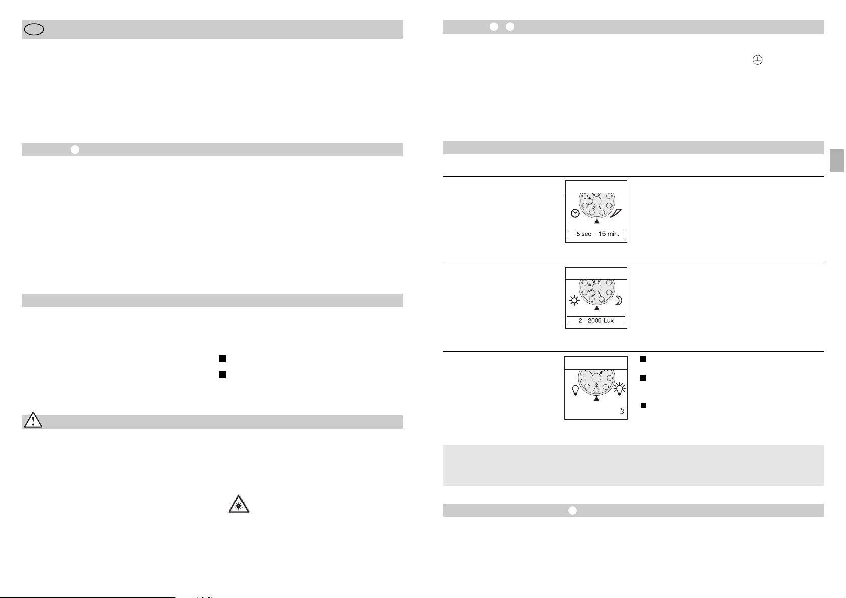
Instalação –
O local de montagem deve encontrar-se a uma distância
mínima de 50 cm de outro candeeiro, pois a radiação térmica
pode ocasionar a activação errada do sensor. A altura de
montagem não deve ultrapassar aprox. 2 m, para obter o
alcance máximo de 12 m. Monte o aparelho sobre uma
superfície firme para evitar ligações erradas.
O cabo proveniente da rede é formado por um conjunto
de 3 fios:
- 31 -
Funções
Retardamento na inactivação
(Ajuste do tempo)
(valor de fábrica: 5 s)
Duração da luz da lâmpada progressivamente regulável de
5 s a 15 min.
Regulador no número 1 (limite esquerdo) =
tempo mais curto (5 s).
Regulador no número 6 (limite direito) =
tempo mais longo (15 min).
Ao determinar a área de detecção, é recomendável escolher
o tempo mais curto 1.
Luminosidade básica
(Regulação de fábrica: programa 1)
Projector LIGA ao detectar movimento a partir do limiar
crepuscular definido / sem luminosidade básica.
Projector LIGA ao detectar movimento a partir do limiar
crepuscular definido / + luminosidade básica (10%)
durante 10 min. depois de decorrido o tempo definido.
Projector LIGA a partir do valor crepuscular predefinido /
+ luminosidade básica (10%) noite inteira.
Regulação crepuscular
(Limiar de resposta)
(Regulação de fábrica:
regime diurno 2000 lux)
O limiar de resposta do sensor pode ser regulado progressivamente de 2 a 2000 lux.
Regulador no número 1 (limite esquerdo) =
regime diurno (aprox. 2000 lux).
Regulador no número 6 (limite direito) =
regime crepuscular (aprox. 2 lux).
Para regular a área de detecção à luz do dia, o regulador tem
de estar em 1 (regime diurno).
LED 10% OFF / 10 min. / ~
1
2
Todas as funções podem ser ajustadas depois de retirar
o friso anelar.
O que significa luminosidade básica ?
A luminosidade básica permite a iluminação com aprox.
10 % da potência luminosa. A luz só se acende (pelo tempo
predefinido, v. retardamento na inactivação
) com
potência luminosa máxima (100 %) ao ser detectado um
movimento dentro da área de detecção. A seguir, a lâmpada
volta por 10 min. para a luminosidade básica (aprox. 10 %).
Regulação do alcance / Ajuste
Consoante a necessidade, a área de detecção pode ser ajustada com precisão. As palas fornecidas servem para cobrir o
número de segmentos de lente necessários para reduzir o
alcance conforme se deseja. Deste modo, podem evitar-se
activações erradas provocadas por ex. por automóveis,
pessoas a passar, etc. ou então monitorar pontos de perigo
específicos. As palas podem ser separadas pelas divisões
pré-marcadas ou cortadas com uma tesoura, quer na horizontal quer na vertical. Depois de retirar o friso anelar, as
palas devem ser engatadas na parte superior da lente do
sensor. Depois de voltar a colocar o friso anelar, as palas
ficam fixadas.
Rodando a caixa do sensor em ± 80 °
pode realizar-se
também um ajuste preciso.
L = fase (geralmente preto ou castanho)
N = neutro (geralmente azul)
PE = condutor terra (verde/amarelo)
Importante: a troca dos conectores provocará mais tarde um
curto-circuito no aparelho ou na caixa dos fusíveis. Nesse
caso, os diversos fios terão de ser identificados e montados
de novo. No cabo de rede pode ser montado um interruptor
de rede apropriado do tipo "ligar - desligar".
- 30 -
Instruções de montagem
Estimado cliente
Agradecemos-lhe a confiança depositada em nós ao comprar
o novo projector LED com sensor da STEINEL. Trata-se de
um produto de elevada qualidade produzido, testado e embalado com o máximo cuidado.
P
Considerações em matéria de segurança
■
Antes de executar qualquer trabalho no aparelho,
desligue-o da corrente!
■
Durante a montagem, o cabo eléctrico a conectar
deve estar isento de tensão. Para tal, desligue primeiro
da corrente e verifique se não há tensão, usando o
busca-pólos.
■
A instalação do sensor consiste essencialmente em lidar
com tensão de rede. Por esse motivo, terá de ser realizada
de forma profissional segundo as respectivas prescrições
de instalação e condições de conexão habituais nos diversos países (
D
-VDE 0100, A-ÖVE/ÖNORM E 8001-1,
-SEV 1000)
Procure familiarizar-se com estas instruções de montagem
antes da instalação. Só uma instalação e colocação em
funcionamento correctas podem garantir a longevidade do
produto e um funcionamento fiável e isento de falhas.
Fazemos votos que tenha prazer ao trabalhar com o seu
novo projector LED com sensor da STEINEL.
■
Não monte o aparelho em cima de superfícies
facilmente inflamáveis.
■
Apropriado para aplicações no interior e exterior.
■
O projector LED com sensor é indicado apenas para a
montagem na parede e não para a montagem no tecto.
■
Em funcionamento, o corpo do projector aquece. Alinhar
a cabeça LED apenas quando esta estiver fria.
■
Não olhe directamente para o candeeiro LED,
nem por demasiado tempo (>5 min.).
O desrespeito a esta indicação pode causar
lesões na retina.
O princípio
O movimento acciona a luz, o alarme e muitas outras coisas,
para seu conforto e para a sua segurança. Seja a nível privado, para iluminar o seu quintal e o terreno ou na área comercial, por ex. para iluminar o terreno da empresa, este projector LED com sensor pode ser montado em qualquer lugar
com rapidez e facilidade, ficando logo pronto a funcionar.
Os projectores LED com sensor XLed 10 e XLed 25 estão
equipados com dois sensores pireléctricos de 120° que
detectam a radiação térmica invisível de corpos em movimento (pessoas, animais, etc.). Esta radiação térmica detectada é transformada por via electrónica e liga o projector.
A radiação térmica não é detectável através de obstáculos,
tais como, por ex., paredes ou vidros. Os dois sensores pireléctricos cobrem um ângulo de detecção de 240º, com um
ângulo de abertura de 180º.
Importante: será possível detectar os movimentos de forma
mais segura se o aparelho estiver instalado lateralmente em
relação ao sentido de aproximação e se não houver obstáculos (como por ex. árvores, muros, etc.), que impeçam a captação pelo sensor.
Descrição do aparelho
Cabeça LED com design plano
Braço articulado
Dissipadores de calor
Suporte de fixação à parede com alimentador de rede
Unidade sensórica
Bujão vedante
Palas
O princípio
Ajuste do tempo
Afinação crepuscular
Regulação da luminosidade básica
Ajuste do alcance/ajuste da área de detecção
Função de luz permanente
Ligação à rede eléctrica, cabo proveniente
da rede embutido
Ligação à rede eléctrica, cabo proveniente
da rede saliente
I
II
P
3
Page 17

- 33 -
Garantia de funcionamento
Este produto STEINEL foi fabricado com todo o zelo e o seu
funcionamento e segurança verificados, de acordo com as
normas em vigor, e sujeito a um controlo por amostragem
aleatória. A STEINEL garante o bom estado e o bom funcionamento do aparelho.
O prazo de garantia é de 36 meses a contar da data de compra. Eliminamos falhas relacionadas com defeitos de material
ou de fabrico. A garantia inclui a reparação ou a substituição
das peças com defeito, de acordo com o nosso critério,
estando excluídas as peças sujeitas a desgaste, os danos e
as falhas originados por uma utilização ou manutenção incorrecta. Excluem-se igualmente os danos provocados noutros
objectos estranhos ao aparelho.
Os serviços previstos na garantia só serão prestados caso o
aparelho seja apresentado bem embalado no respectivo serviço de assistência técnica, devidamente montado e acompanhado do talão da caixa ou da factura (data da compra
e carimbo do revendedor) e de uma pequena descrição do
problema.
Serviço de reparação:
Depois de expirado o prazo de garantia ou
em caso de falha não abrangida pela
garantia, o nosso serviço de assistência
técnica encarregar-se-á da reparação do
seu aparelho. Basta enviar o produto bem
acondicionado ao nosso centro de assistência técnica mais
próximo de si.
Declaração de conformidade
O produto cumpre as Directivas do Conselho "Baixa tensão"
2006/95/CE, "Compatibilidade electromagnética"
2004/108/CE e "Redução de substâncias perigosas"
2002/95/CE.
Falhas de funcionamento
Projector LED com sensor
sem tensão
O projector LED com sensor
não se acende
O projector LED com sensor
não se apaga
O projector LED com sensor
acende-se inadvertidamente
Falha
■
Fusível queimado, não ligado,
ligação interrompida
■
Curto-circuito
■
Fusível novo, ligar interruptor de
rede; verificar o cabo com detector
de tensão
■
Verificar as conexões
■
Em regime diurno, regulação crepuscular encontra-se em regime
nocturno
■
Interruptor de rede DESLIGADO
■
Fusível fundido
■
Área de detecção ajustada
incorrectamente
■
Reajustar
■
Ligar
■
Fusível novo, verificar
eventualmente a conexão
■
Reajustar
■
Movimento constante na área
de detecção
■
Examinar a área e eventualmente
reajustar ou cobrir com pala
■
O vento agita árvores e arbustos na
área de detecção
■
São detectados automóveis a passar na estrada
■
Alteração térmica súbita devido a
influências climatéricas (vento, chuva, neve) ou ar evacuado de ventiladores, janelas abertas
■
Projector LED com sensor oscila
(mexe-se) por ex. devido a rajadas
de vento ou chuva forte.
■
Modificar a área
■
Modificar a área
■
Modificar a área, mudar para outro
local de montagem
■
Montar o projector LED com
sensor numa base firme
Causa Solução
O projector LED com sensor
está sempre a acender/apagar
■
Encontram-se animais dentro
da área de detecção
■
Virar o sensor para cima ou tapar
determinadas partes; Mudar a área
de detecção ou cobrir com pala
- 32 -
Funcionamento e conservação
O aparelho não se adequa a sistemas de alarme anti-roubo
especiais, uma vez que não está garantida a protecção contra sabotagem exigida por lei. As influências climatéricas
podem deteriorar o funcionamento do projector LED com
sensor. As rajadas fortes de vento, a neve, a chuva e o grani-
zo podem causar uma activação errada, porque o sistema
não consegue distinguir entre alterações súbitas de temperatura e irradiação proveniente de fontes de calor.
Se estiver suja, a lente de detecção pode ser limpa com um
pano húmido (sem usar produtos de limpeza).
Função de iluminação permanente
Se for montado um interruptor de corrente no cabo proveniente da rede, além das meras funções de ligar e desligar
do candeeiro conectado, ainda são possíveis as funções
seguidamente enunciadas:
Funcionamento do sensor
1) Ligar a luz (estando o projector DESLIGADO):
Interruptor 1 vez DESLIGA e LIGA.
LEDs continuam acesos durante o tempo predefinido.
2) Apagar a luz (estando o projector LIGADO):
Interruptor 1 vez DESLIGA e LIGA.
O projector desliga-se ou passa para o funcionamento
de sensor.
Funcionamento de luz permanente
1) Ligar a luz permanente:
Interruptor 2 vezes DESLIGA e LIGA. O projector é ligado por
4 horas em modo de luz permanente (LED vermelho por
detrás da lente acende-se). A seguir, passa automaticamente
para o funcionamento de sensor (LED vermelho apaga-se)
2) Desligar a luz permanente:
Interruptor 1 vez DESLIGA e LIGA. O projector desliga-se ou
passa para o funcionamento de sensor.
Importante:
Ao accionar o interruptor várias vezes seguidas, os intervalos devem ser mínimos (na ordem de 0,5 – 1 s).
Dados técnicos
Projector LED com sensor XLed 10 XLed 25
Potência: 10 LEDs, aprox. 25 W 25 LEDs, aprox. 60 W
Cor de luz: aprox. 4000 Kelvin (branco quente) aprox. 4000 Kelvin (branco quente)
Intensidade da luz: 960 lúmenes 2120 lúmenes
Potência de comutação suplementar:
Lâmpadas incandescentes, máx. 800 watts a 230 V CA
Tubo fluorescente, máx. 400 watts com cos ϕ = 0,5,
carga indutiva a 230 V CA
Lâmpadas fluorescentes, lâmpadas economizadoras,
candeeiros LED com balastro electrónico a 230 V CA,
4 x máx. de 60 watts cada, C ≤ 88 µF
Vida útil dos LEDs: até 50 000 h até 50 000 h
(assumindo 3 h/dia aprox. 45 anos) (assumindo 3 h/dia aprox. 45 anos)
Ângulo de detecção: 240° com protecção contra 240º com protecção contra
movimentos dissimulados movimentos dissimulados
Área projectada 250 cm2+ 103,36 cm
2
420 cm2+ 103,36 cm
2
Orientação da unidade sensórica: ± 80° ± 80°
Margem de orientação corpo: vertical 200° vertical 200°
horizontal 270° horizontal 270°
Ajuste do tempo: 5 s – 15 min 5 s – 15 min
Regulação crepuscular: 2 – 2000 lux 2 – 2000 lux
Regulação da intensidade luminosa: luminosidade básica 10% (aprox. 3 W) luminosidade básica 10% (aprox. 6 W)
Luz permanente: regulável até 4 h regulável até 4 h
Dimensões (alt. x larg. x prof.) 205 x 200 x 220 mm 300 x 200 x 220 mm
Peso: 2200 g 2960 g
Intervalo de temperatura: -20 °C até +50 °C -20 °C até +50 °C
Grau de protecção: IP 44 IP 44
Classe de protecção: I I
P
Page 18

Installation –
Produkten bör vara monterad minst 50 cm från
andra lampor annars kan värmestrålningen orsaka
feldekteringar på sensorn. För att uppnå räckvidd
12 m ska montagehöjden vara cirka 2 meter över
mark. Strålkastaren måste vara monterad på ett
stabilit underlag för att undvika feldetekteringar.
Nätkabeln består av en 2-3 ledarkabel:
L = Fas
N = Nolledare
PE = Skyddsledare
- 35 -
Funktioner
Efterlystid (tidsinställning)
(fabriksinställning 5 sek.)
Kan steglöst ställas in från
ca 5 sekunder till 15 minuter.
Ställskruven i läge 1 (vänster ändläge) =
kortaste tiden (5 sek.)
Ställskruven i läge 6 (höger ändläge) =
längsta tiden (15 min)
Vid inställning av bevakningsområde och för funktionstest
är det lämpligast att den kortaste tiden är inställd.
Grundljus
(fabriksinställning, program 1)
Strålkastaren tänds vid rörelse, inget grundljus.
Strålkastaren tänds vid rörelse + 10% grundljus
i 10 minuter efter att efterlystiden har löpt ut.
Strålkastaren tänds med vid rörelse samt lyser
med + 10% grundljus under hela natten. Det
förutsätter att skymningsvärdet att inställt på
mörkerdrift.
Skymningsinställning
(aktiveringströskel)
(fabriksinställning,
dagsljusdrift 2000 lux)
Kan steglöst ställas från ca. 2 – 2000 lux.
Ställskruven i läge 1 (vänster ändläge) =
dagsljusdrift ca 2000 lux
Ställskruven i läge 6 (höger ändläge) =
skymningsdrift 2 lux.
Vid inställning av bevakningsområdet i dagsljus
måste ställskruven vara ställd på 1 (dagsljusdrift).
LED 10% OFF / 10 min. / ~
1
2
Inställning av funktioner kan göras genom att man
drar bort täckringen
Vad är grundljus?
Grundljus ger möjlighet att låta strålkastaren vara tänd
med 10% av full ljusstyrka. Vid rörelse i sensorns
bevakningsområde tänder strålkasten upp med fullt
ljus och är tänd enligt den inställda efterlystiden.
När efterlystiden har löpt ut övergår strålkastaren till
att lysa med 10% ljus i 10 minuter alternativt hela
natten. Därefter är den helt släckt.
Inställning/justering av räckvidd
För att avgränsa vissa områden som t. ex. gångvägar
eller granntomt kan bevakningsområdet fininställas
genom montering av täckskal. Täckskalen kan brytas
av eller klippas med sax längs den spårade indelningen i lodräta och vågräta avsnitt. Genom att lossa på
täckringen kan täckskalen hängas i linsens ovankant.
Sätt sedan tillbaka täckringen och täckskalen är fast
förankrade.
Man kan även fininställa bevakningsområdet genom
att vrida/svänga sensorhuset upp till ± 80°
OBS! En förväxling av kablarna leder till kortslutning
i LED-strålkastaren eller i säkringsskåpet. Om du
är osäker måste du identifiera kablarna med en
spänningsprovare. På nätledningen kan självklart en
strömställare för till- och frånslagning vara monterad.
- 34 -
Bruksanvisning
Bäste kund,
Tack för det förtroende Du har visat genom att köpa
en STEINEL sensorprodukt. Du har valt en högvärdig
kvalitetsprodukt, producerad, testad och förpackad
med största noggrannhet. Vi ber dig att noga läsa
S
Säkerhetsanvisningar
■ Innan installation och montage påbörjas måste
spänningen kopplas bort.
■ Inkoppling måste utföras i spänningsfritt tillstånd.
Bryt strömmen och kontrollera med spänningsprovare att alla parter är spänningslösa.
■ Eftersom LED-strålkastaren installeras till nätspänningen måste arbetet utföras på ett fackmannamässigt sätt och enligt gällande installationsföreskrifter.
igenom denna montageanvisning innan du installerar
LED-strålkastaren. Korrekt installation och idrifttagning är en förutsättning för långvarig och tillförlitlig
drift.
Vi hoppas du får stor nytta av LED-strålkastaren.
■ Montera inte strålkastaren på lättantändligt
underlag.
■ Strålkastaren kan användas utom- eller inomhus.
■ Strålkastaren är avsedd för väggmontage och kan
inte monteras i tak.
■ Under drift blir lamphuset mycket varmt. Rikta in
LED-strålkastaren efter den har blivit avkyld.
■ Om man utsätter sig för skenet från en
LED-strålkastare på nära håll eller under
en längre tid (< 5 min. ) kan det uppstå
hudirritation.
Princip
Rörelse tänder och släcker ljus, startar larm etc. för
komfort, säkerhet och energibesparing. LED-strålkastaren är försedd med en pyro-sensor som känner av
värmestrålningen från kroppar i rörelse (människor,
djur etc.)
Den registrerade värmestrålningen omvandlas på
elektronisk väg och tänder armaturen. Murar, fönster
etc. hindrar värmestrålningen från att nå fram till
sensorn och ger följaktligen ingen tändning eller
släckning av ljuset.
Viktigt: Den säkraste rörelsebevakningen uppnås när
sensorn är placerad i rät vinkel mot rörelseriktningen
och inga hinder (t.ex. murar, träd etc.) finns i vägen.
Produktbeskrivning
LED-huvud
Svängarm
Kylelement
Väggfäste med nätdel
Sensorenhet
Tätning – förskruvning
Täckskal
Princip
Tidsinställning
Skymningsinställning
Inställning av grundljus
Inställning av sensorns räckvidd
Permanent ljus – tvångständning
Anslutning med infälld kabel
Anslutning utanpåliggande kabel
I
II
S
3
Page 19

- 37 -
Funktionsgaranti
Denna STEINEL produkt är tillverkad med största
noggrannhet. Den är funktions- och säkerhetstestad
enligt gällande föreskrifter och har därefter genomgått
en stickprovskontroll. Steinel garanterar felfri funktion.
Garantin gäller i 36 månader från inköpsdagen. Vi
återgärdar fel som beror på material- eller tillverkningsfel. Garantin innebär att varan repareras eller
att defekt del byts ut enligt vårt val. Garantin omfattar
inte slitage och skador orsakade av felaktig hanterande eller av bristande underhåll och skötsel av produkten. Följskador på främmande föremål ersätts ej.
Garantin gäller endast då produkten, som inte får
vara isärtagen, lämnas väl förpackad med fakturakopia eller kvitto (inköpsdatum och stämpel) till vår återförsäljare för åtgärd.
Reparationsservice:
Efter garantins utgång eller vid fel
som inte omfattas av garantin kan
produkten, om möjligt, repareras
på vår serviceverkstad. Vänligen
kontakta oss innan Ni sänder tillbaka
produkten för reparation.
- överensstämmelseförsäkran
Produkten uppfyller lågspänningsdirektivet direktivet
2006/95/EG, EMC-direktivet 2004/108/EG och
RoHS riktlinjerna 2002/95/.
Betriebsstörungen
LED-strålkastaren utan spänning
LED-strålkastaren tänds inte
LED-strålkastaren slocknar inte
LED-strålkastaren tänds oönskat
Störning
■ Defekt säkring, brott i kabel
■ Kortslutning
■ Byt säkring, testa med
spänningsprovare
■ Kontrollera och testa kopplingar
■ Vid drift på dagen, skymningsin-
ställningen inställd på nattdrift
■ Strömställare frånslagen
■ Defekt säkring
■ Bevakningsområdet felinställt
■ Ändra skymningsnivån till rätt
läge
■ Slå till strömställaren
■ Byt säkring, kontrollera
ev. anslutningen
■ Justera inställningen
■ Ständiga rörelser
i bevakningsområdet
■ Kontrollera bevakningsområdet.
Vid behov justera och begränsa
området
■ Blåst i träd och buskar i
bevakningsområdet
■ Påverkan från bilar på gatan
■ Plötsliga temperatur förändring-
ar genom vädrets inverkan
(vind, regn, snö) eller fläktutlopp,
öppet fönster
■ Strålkastaren rör sig pga starka
vindbyar eller kraftigt regn
■ Justera eller avskärma
bevakningsområdet
■ Justera eller avskärma
bevakningsområdet
■ Justera bevakningsområdet
eller flytta strålkastaren
■ Montera strålkastaren på ett
stabilare underlag
Orsak Åtgärd
LED-strålkastaren tänds och släcks
ständigt
■ Djur rör sig i bevakningsområdet ■ Kontrollera bevakningsområdet.
Vid behov justera och begränsa
området
- 36 -
Drift / Underhåll
LED-strålkastaren med sensor är avsedd för automatisk tändning av ljus. Produkten är inte lämplig att
använda som inbrottslarm eftersom den föreskrivna
säkerheten mot sabotage saknas. Vädret kan påverka
strålkastarens funktion. Vid kraftiga vindbyar, snö,
regn eller hagel kan det ske felaktiveringar eftersom
sensorn inte kan skilja de plötsliga temperaturskillnaderna från värmekällor. När linsen är smutsig kan den
rengöras med en fuktig trasa (utan rengöringsmedel).
Permanent ljus
Om en strömbrytare kopplas in på nätledningen före
strålkastare är följande funktioner
enkelt möjliga genom vippa brytaren till-från:
Sensordrift
1. Tända lampan (när lampan är släckt):
Manövrera brytaren 1 x AV och PÅ.
Lampan lyser lika länge som den inställda efterlystiden.
2. Släcka ljuset (när lampan är tänd):
Manövrera brytaren 1 x AV och PÅ.
Lampan släcks och övergår i sensordrift.
Permanent ljus
1. Tända lampan med permanent ljus:
Manövrera brytaren 2 x AV och PÅ. Lampan lyser med
permanent ljus (full effekt) i 4 timmar (röd LED-lampa
lyser bakom linsen). Efter 4 timmar övergår lampan
automatiskt till sensordrift (röd LED-lampa lyser inte).
2. Släcka lampa med permanent ljus:
Manövrera brytaren 1 x AV och PÅ. Lampan släcks
och övergår i sensordrift.
OBS:
Flerfaldiga manövreringar av brytaren måste ske
snabbt efter varandra, inom 0,5–1 sek.
Tekniska data
Sensor LED-strålkastare XLed 10 XLed 25
Effekt: 10 LEDs, ca. 25 W 25 LEDs, ca. 60 W
Ljusfärg: ca. 4000 K. ca. 4000 K.
Ljusflöde: 960 Lumen 2120 Lumen
Maximal extern belastning:
800W resistiv last
Max 4st lågenergilampor alt. drosslar/HF-don
dock total last max 400W
Lysrör, lågenergilampor, LED-lampor med elektroniskt
förkoppl.don vid 230 V AC, 4 x max. à 60 W, C ≤88
µF
Livslängd LED: upp till 50.000 timmar upp till 50.000 timmar
Sensorns bevakningsvinkel: 240° med underkrypskydd 240° med underkrypskydd
Belyst yta: 250 cm2+ 103,36 cm
2
420 cm2+ 103,36 cm
2
Sensor-enhetens rörlighet: ± 80° ± 80°
Sensorhusets rörlighet: vertikal 200° vertikal 200°
horisontal 270° horisontal 270°
Efterlystid: 5 Sek. – 15 Min. 5 Sek. – 15 Min.
Skymningsnivå: 2 – 2000 Lux 2 – 2000 Lux
Grundljus (dimring): 10% grundljus (ca. 3 W) 10% grundljus (ca. 6 W)
Permanentljus: 4 timmar inställbart 4 timmar inställbart
via väggströmställare via väggströmställare
Mått (HxBxD): 205 x 200 x 220 mm 300 x 200 x 220 mm
Vikt: 2200g 2960g
Omgivningstemperatur: -20 °C bis +50 °C -20 °C bis +50 °C
Skyddsklass: IP 44 IP 44
Isolationsklass: I I
S
Page 20
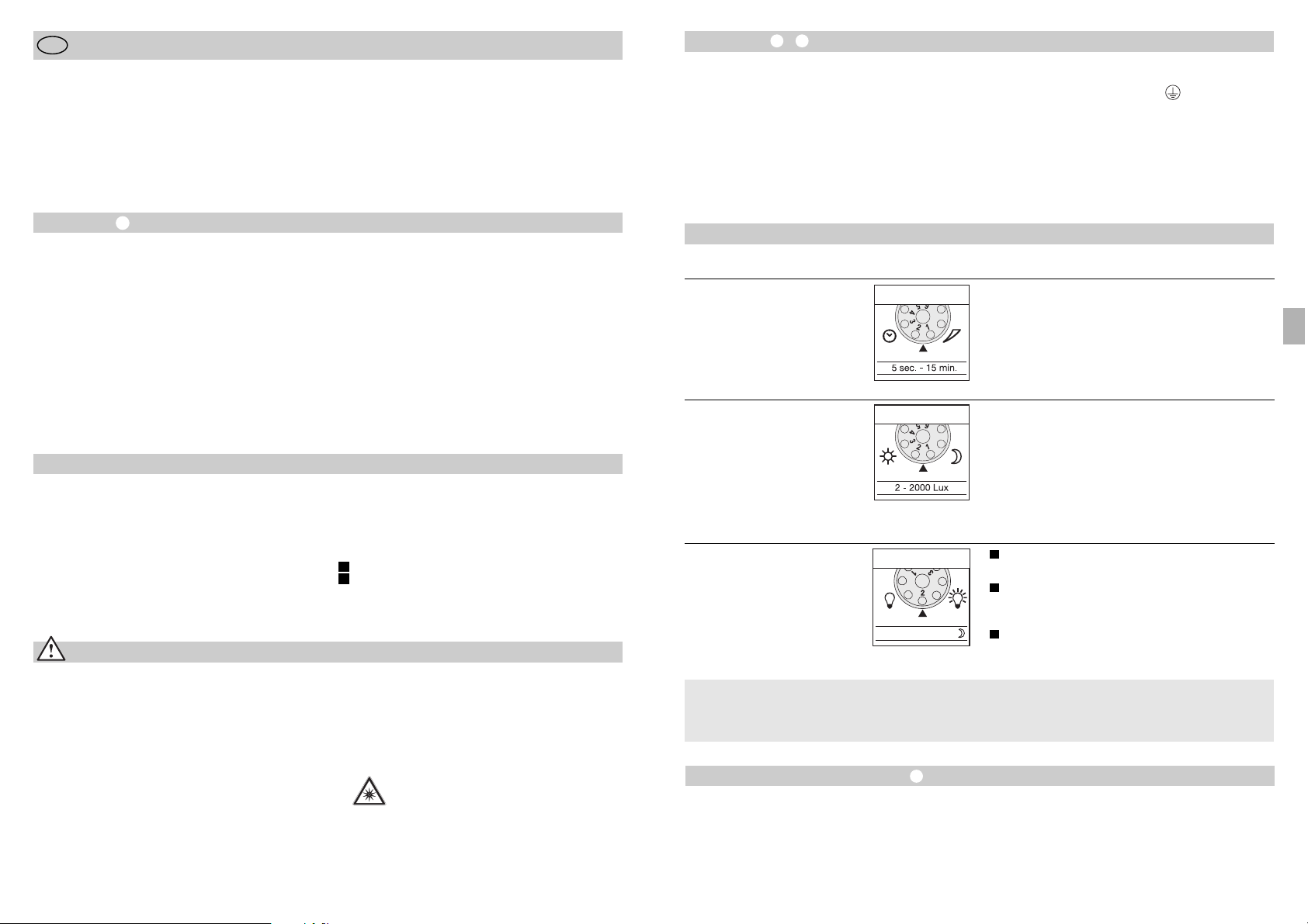
Installation –
Monteringsstedet bør have en afstand på mindst
50 cm til andre lyskilder, da varmestrålingen kan
medføre aktivering af systemet. For at opnå den
anførte rækkevidde på maks. 12 m bør apparatet
monteres i ca. 2 m højde. Monter det på et fast
underlag for at undgå fejlaktivering.
Nettilledningen består af et 3-leder kabel:
- 39 -
Funktioner
Frakoblingsforsinkelse
(tidsindstilling)
(fabriksindstilling: 5 sek.)
Brændetiden kan indstilles trinløst fra 5 sek. til 15 min.
Indstillingsknappen indstillet på 1 (helt til venstre) =
korteste tid (5 sek.)
Indstillingsknappen indstillet på 6 (helt til højre) =
længste tid (15 min.)
For indstilling af overvågningsområdet anbefaler vi at
vælge den korteste tid 1.
Basislysstyrke
(fabriksindstilling: program 1)
Lampen tænder ved bevægelse fra den indstillede
skumringsværdi / ingen basislysstyrke.
Lampen tænder ved bevægelse fra den indstillede
skumringsværdi / + basislysstyrke (10 %) i 10 min.
efter den indstillede tid er udløbet.
Lampen tænder ved bevægelse fra den indstillede
skumringsværdi / + basislysstyrke (10 %) hele
natten.
Skumringsindstilling
(reaktionsværdi)
(fabriksindstilling:
dagsmodus 2.000 lux)
Reaktionsværdien kan indstilles trinløst fra
2 til 2.000 lux.
Indstillingsknappen indstillet på 1 (helt til venstre) =
dagsmodus ca. 2.000 lux.
Indstillingsknappen indstillet på 6 (helt til højre) =
skumringsmodus ca. 2 lux.
For indstilling af overvågningsområdet i dagslys skal
indstillingsknappen indstilles på 1 (dagsmodus).
LED 10% OFF / 10 min. / ~
1
2
Alle funktioner kan indstilles, når dækringen er
taget af.
Hvad er basislysstyrke?
Basislysstyrken giver mulighed for belysning med ca.
10 % lysstyrke. Først ved bevægelse i overvågningsområdet skifter lyset (i den indstillede tid, se
Frakoblingsforsinkelse ) til maksimal lysstyrke
(100 %). Herefter skifter lampen i 10 min. til basislysstyrke (ca. 10 %).
Rækkeviddeindstilling/justering
Overvågningsområdet kan indstilles efter behov. Ved
hjælp af de vedlagte blændstykker kan man afdække
et vilkårligt antal linsesegmenter eller reducere rækkevidden individuelt. På den måde kan man udelukke
fejlkobling på grund af f.eks. biler, forbipasserende osv.
samt overvåge farezoner målrettet. Blændstykkerne
kan afrives langs de lodrette og vandrette perforeringer
eller klippes ud med en saks. Efter afmontering af
dækringen skal de monteres øverst på sensorlinsen.
Derpå skal dækringen sættes på igen, så blændstykkerne fastgøres ordentligt. Ved at dreje sensorkabinettet ± 80° er det muligt at foretage finjustering.
L = fase (normalt sort eller brun)
N = neutralleder (normalt blå)
PE = beskyttelsesleder (grøn/gul)
Vigtigt: Hvis disse forbyttes, vil det senere medføre
kortslutning i apparatet eller i sikringsskabet. I så fald
skal de enkelte ledninger identificeres og monteres
på ny. I nettilledningen kan der monteres en egnet
tænd- og slukkontakt.
- 38 -
Monteringsvejledning
Kære kunde
Tak for den tillid, du har vist os, ved at købe den nye
sensor-LED-lampe fra STEINEL. Du har valgt et produkt af høj kvalitet, som er fremstillet, testet og
emballeret med største omhu.
DK
Sikkerhedsanvisninger
■ Afbryd spændingstilførslen, inden du arbejder på
apparatet!
■ Ved montering skal den elledning, der skal tilsluttes, være spændingsfri. Afbryd derfor strømmen og
kontroller med en spændingstester, at ledningen er
spændingsfri.
■ Ved installation af disse apparater er der tale
om arbejde med netspænding. Installationen
skal derfor udføres fagligt korrekt iht. de gældende
regler.
Læs venligst monteringsvejledningen, før du installerer lampen, for kun korrekt installation og ibrugtagning sikrer en lang, pålidelig og fejlfri drift.
Vi ønsker dig god fornøjelse med den nye sensorLED-lampe fra STEINEL.
■
Apparatet må ikke monteres på let brændbare
overflader.
■ Egnet til både udendørs og indendørs brug
(op til 25° C rumtemperatur).
■ Sensor-LED-lampen er kun beregnet til
vægmontering, ikke til loftmontering.
■ Kabinettet bliver varmt, når lampen er tændt.
LED-hovedet må først indstilles, når det er kølet af.
■ Se ikke ind i LED-pæren på kort afstand
eller i længere tid (> 5 min.), da dette kan
medføre beskadigelse af nethinden.
Princippet
Bevægelser aktiverer lys, alarm og meget mere. For
mere komfort og sikkerhed. Både privat til belysning
af hus og have og erhvervsmæssigt til f.eks. belysning af virksomhedens område - sensor-LED-lampen
er nem og hurtig at montere.
Sensor-LED-lamperne XLed 10 og XLed 25 er udstyret med to 120°-pyrosensorer, der registrerer den
usynlige varmestråling fra objekter, der bevæger sig
(mennesker, dyr osv.). Den registrerede varmestråling
omsættes elektronisk og tænder lampen. Ved forhindringer som f.eks. mure eller vinduer registreres der
ingen varmestråling. Ved hjælp af de to pyrosensorer
opnås der en registreringsvinkel på 240° med en
åbningsvinkel på 180°.
Vigtigt: Den bedste overvågning opnår du ved at
montere apparatet vinkelret i forhold til gåretningen
og der ikke er objekter (f.eks. træer, mure osv.), der
blokerer dets synsfelt.
Beskrivelse
LED-hoved i et fladt design
Bevægelig arm
Køleribber
Vægbeslag med strømforsyning
Sensorenhed
Lukkeprop
Blændstykker
Princippet
Tidsindstilling
Skumringsindstilling
Indstilling basislysstyrke
Rækkeviddeindstilling/justering af
overvågningsområde
Funktionen permanent belysning
Nettilslutning skjult ledningsføring
Nettilslutning synlig ledningsføring
I
II
DK
3
Page 21

- 41 -
Funktionsgaranti
Dette Steinel-produkt er fremstillet med største omhu,
afprøvet iht. de gældende forskrifter samt underlagt
stikprøvekontrol. STEINEL garanterer for upåklagelig
beskaffenhed og funktion.
Garantien gælder i 36 måneder fra den dag, apparatet er solgt til forbrugeren. Ved materiale- og fabrikationsfejl ydes garantien gennem reparation eller
ombytning efter vort valg. Der ydes ikke garanti ved
skader på sliddele, ej heller ved skader og mangler,
som skyldes ukorrekt behandling og vedligeholdelse.
Garantien omfatter ikke følgeskader på fremmede
genstande.
Der ydes kun garanti mod forevisning af en kort fejlbeskrivelse samt en bon eller kvittering (med dato og
stempel). Derudover skal apparatet være intakt og
indpakket forsvarligt, når det fremsendes til serviceværkstedet.
Reparationsservice:
Efter garantiperiodens udløb eller ved
fejl, der ikke er dækket af garantien,
kan apparatet repareres på vores
værksted. Sørg for, at produktet er
pakket forsvarligt ind under forsendelsen til nærmeste
serviceværksted.
Konformitetserklæring
Produktet er i overensstemmelse med lavspændingsdirektivet 2006/95/EF, EMC-direktivet 2004/108/EF
samt RoHS-direktivet 2002/95/EF.
Driftsforstyrrelser
Sensor-LED-lampen
uden spænding
Sensor-LED-lampen tænder ikke
Sensor-LED-lampen slukker ikke
Sensor-LED-lampen
tænder utilsigtet
Fejl
■ Sikringen er defekt, ikke tændt,
ledningen er afbrudt
■ Kortslutning
■ Udskift sikringen, tænd for
tænd- og slukkontakten,
kontroller ledningen med en
spændingstester
■ Kontroller tilslutningerne
■ Ved brug i dagslys, skumrings-
indstillingen er indstillet på
natmodus
■ Tænd- og slukknappen slukket
■ Sikring defekt
■ Overvågningsområdet er ikke
indstillet korrekt
■ Indstil på ny
■ Tænd
■ Udskift sikringen,
kontroller evt. tilslutningen
■ Juster på ny
■ Konstant bevægelse
i overvågningsområdet
■ Kontroller området og evt.
indstil eller afdæk på ny
■ Vinden får træer og buske
i overvågningsområdet til at
bevæge sig
■ Registrering af biler på vejen
■ Pludselige temperatursving-
ninger pga. vejret (vind, regn
og sne) eller luft fra ventilatorer
og åbne vinduer
■ Sensor-LED-lampen bevæger
sig f.eks. på grund af vindstød
eller kraftig nedbør
■ Indstil området på ny
■ Indstil området på ny
■ Ændr området,
flyt monteringssted
■ Monter sensor-LED-lampen
på et fast underlag
Årsag Afhjælpning
Sensor-LED-lampen tænder
og slukker hele tiden
■ Dyr i overvågningsområdet ■ Drej sensoren opad eller
afdæk den, afdæk eller
indstil området på ny
- 40 -
Drift og vedligeholdelse
Apparatet er ikke velegnet til særlige tyverialarmer, da
den foreskrevne sabotagesikring mangler. Vejr og vind
kan påvirke sensor-LED-lampens funktion. Ved kraftige vindstød, sne, regn og hagl kan der opstå fejlkob-
ling, idet pludselige temperatursvingninger ikke kan
skelnes fra varmekilder.
Overvågningslinsen aftørres med en fugtig klud
(uden rengøringsmiddel).
Funktionen permanent belysning
Hvis der monteres en tænd- og slukkontakt i nettilledningen, er følgende funktioner mulige foruden tænd
og sluk:
Sensorstyring
1) Tænde lyset (når lampen er slukket):
Kontakt 1 x SLUK og TÆND.
LED'erne er tændt i den indstillede tid.
2) Slukke lyset (når lampen er tændt):
Kontakt 1 x SLUK og TÆND.
Lampen slukker eller skifter til sensorstyring.
Permanent belysning
1) Tænde for permanent belysning:
Kontakt 2 x SLUK og TÆND. Lampen indstilles på
permanent belysning i 4 timer (rød LED lyser bag
linsen). Derefter skifter den automatisk til sensorstyring (rød LED slukket).
2) Slukke for permanent belysning:
Kontakt 1 x SLUK og TÆND. Lampen slukker eller
skifter til sensorstyring.
Vigtigt:
Hvis kontakten skal aktiveres flere gange, bør dette
ske hurtigt efter hinanden (inden for 0,5 – 1 sek.).
Tekniske data
Sensor-LED-lampe XLed 10 XLed 25
Effekt: 10 LED'er, ca. 25 W 25 LED'er, ca. 60 W
Lysfarve: ca. 4000 kelvin (varm hvid) ca. 4000 kelvin (varm hvid)
Lysstrøm: 960 lumen 2120 lumen
Supplerende effekt:
Elpærer, maks. 800 W ved 230 V AC
Lysstofrør, maks. 400 W ved cos ϕ = 0,5,
induktiv belastning ved 230 V AC
Lysstofrør, energisparepærer,
LED-lamper med elektronisk forkoblingsenhed ved 230 V AC,
4 x maks. pr. 60 W, C ≤ 88 μF
Levetid LED'er: op til 50.000 timer op til 50.000 timer
(ved 3 timer/dag ca. 45 år) (ved 3 timer/dag ca. 45 år)
Registreringsvinkel: 240° med krybesikring 240° med krybesikring
Belyst flade: 250 cm2+ 103,36 cm
2
420 cm2+ 103,36 cm
2
Sensorenhedens
drejeradius: ± 80° ± 80°
Kabinettets drejeradius: lodret 200° lodret 200°
vandret 270° vandret 270°
Tidsindstilling: 5 sek. – 15 min. 5 sek. – 15 min.
Skumringsindstilling: 2 – 2.000 lux 2 – 2.000 lux
Lysstyrkeregulering: 10 % basislysstyrke (ca. 3 W) 10 % basislysstyrke (ca. 6 W)
Permanent belysning: 4 timer, kan aktiveres 4 timer, kan aktiveres
Mål (h x b x d): 205 x 200 x 220 mm 300 x 200 x 220 mm
Vægt: 2.200 g 2.960 g
Temperaturområde: -20 °C til +50 °C -20 °C til +50 °C
Kapslingsklasse: IP 44 IP 44
Beskyttelsesklasse: I I
DK
Page 22

Asennus –
Valaisimen kiinnityspaikan tulisi olla vähintään
50 cm etäisyydellä toisesta valaisimesta, sillä läm-
pösäteily voi johtaa valon syttymiseen. Tunnistin on
asennettava noin 2 metrin korkeuteen, jotta annettu
enintään 12 metrin toimintaetäisyys saavutetaan.
Asenna laite kiinteälle alustalle virhekytkentöjen
välltämiseksi.
Verkkojohtona käytetään 3-johtimista kaapelia:
- 43 -
Toiminta
Kytkentäajan asetus
(tehtaalla suoritettu asetus: 5 s)
Portaattomasti asetettava kytkentäaika 5 s – 15 min
Säädin asetettu kohtaan 1 (vasemmanpuoleinen
ääriasento) = lyhin aika (5 s)
Säädin asetettu kohtaan 6 (oikeanpuoleinen
ääriasento) = pisin aika (15 min)
Toiminta-aluetta säädettäessä suosittelemme
valitsemaan lyhimmän ajan 1.
Peruskirkkaus
(Tehtaalla suoritettu asetus:
ohjelma 1)
Valaisin kytkeytyy liikkeen yhteydessä asetetusta
hämäryystasosta alkaen / ei peruskirkkautta.
Valaisin kytkeytyy liikkeen yhteydessä asetetusta
hämäryystasosta alkaen / + peruskirkkaus (10 %)
10 minuutin ajaksi, kun asetettu aika on kulunut
loppuun.
Valaisin kytkeytyy liikkeen yhteydessä asetetusta
hämärätasosta alkaen / + peruskirkkaus (10 %)
koko yön ajan.
Hämäryystason asetus
(kytkeytymiskynnys)
(Tehtaalla suoritettu asetus:
päiväkäyttö, 2000 luksia)
Tunnistimen portaattomasti asetettava kytkeytymiskynnys 2 – 2000 luksia.
Säädin asetettu kohtaan 1 (vasemmanpuoleinen
ääriasento) = noin 2000 luksin päiväkäyttö.
Säädin asetettu kohtaan 6 (oikeanpuoleinen
ääriasento) = noin 2 luksin hämäräkäyttö.
Kun toiminta-alue asetetaan päivänvalossa, säädin
on asetettava asentoon 1 (päiväkäyttö).
LED 10% OFF / 10 min. / ~
1
2
Kaikki toiminnot voidaan säätää,
kun rengassuojus otetaan pois.
MItä peruskirkkaus tarkoittaa ?
Peruskirkkaus mahdollistaa valaistuksen yöllä n.
10 % valoteholla. Vasta toiminta-alueella tapahtuva
liike kytkee valon (säädetyksi ajaksi, ks. kytkentäviive
) suurimmalle valoteholle (100 %). Sen jälkeen
valaisin kytkeytyy 10 minuutiksi peruskirkkaudelle
(n. 10 %).
Toiminta-alueen rajaus/säätö
Toiminta-aluetta voidaan tarvittaessa rajata sopivammaksi. Tunnistimen mukana toimitetuilla linssin suojuksilla voidaan peittää haluttu määrä linssin lohkoja
eli lyhentää toiminta-aluetta yksilöllisesti. Näin voidaan estää esim. autojen tai ohikulkijoiden aiheuttamat virhekytkennät tai rajata tietyt vaara-alueet täsmällisesti. Voit erottaa suojukset toisistaan valmiita
vaaka- ja pystysuoria uria pitkin joko taittamalla tai
saksilla leikkaamalla. Irrota rengassuojus ja ripusta
lohkot tunnistimen linssin yläosaan. Pistä sitten
rengassuojus takaisin paikoilleen, jolloin suojukset
kiinnittyvät.
Hienosäätö on mahdollista kiertämällä tunnistimen
runkoa ± 80°.
L = vaihe (useimmiten musta tai ruskea)
N = nollajohdin (useimmiten sininen)
PE = maadoitusjohdin (vihreä/keltainen)
Tärkeää: Liitäntöjen sekaantuminen johtaa oikosul-
kuun laitteessa tai sulakekotelossa. Tässä tapauksessa yksittäiset johtimet on tunnistettava ja asennettava uudelleen. Verkkojohtoon voidaan asentaa
sopiva virtakytkin virran kytkemiseksi ja katkaisemiseksi.
- 42 -
Asennusohje
Arvoisa asiakas,
Olet ostanut STEINELin LED-valonheittimen. Kiitämme osoittamastasi luottamuksesta. Olet hankkinut
laatutuotteen, joka on valmistettu, testattu ja pakattu
huolellisesti.
FIN
Turvaohjeet
■ Katkaise jännitteensyöttö aina, ennen kuin suoritat
laitteelle mitään toimenpiteitä!
■ Asennus on tehtävä jännitteettömänä.
Katkaise ensin virta ja tarkista jännitteettömyys
jännitteenkoettimella.
■ Laite liitetään verkkojännitteeseen. Asennus on
suoritettava asiantuntevasti. Voimassa olevia
asennus- ja liitäntäohjeita on noudatettava.
Tutustu ennen valaisimen asennusta tähän asennusohjeeseen. Ainoastaan asianmukainen asennus ja
käyttöönotto takaavat laitteen pitkäaikaisen, luotettavan ja häiriöttömän toiminnan.
■ Soveltuu käytettäväksi ulkona ja sisällä.
■ LED-tunnistinvalaisin on suunniteltu asennettavaksi
ainoastaan seinään. Sitä ei saa asentaan kattoon.
■ Valaisimen kotelo lämpenee käytön aikana.
Kohdista LED-taulu vasta, kun se on jäähtynyt.
■ Älä katso LED-valoon liian läheltä tai
liian kauan (> 5 min). Verkkokalvo voi
vioittua.
Toimintaperiaate
Liike kytkee valon, hälytyksen tai jonkin muun toiminnon. Tämä lisää käyttömukavuutta ja turvallisuutta.
Tätä LED-tunnistinvalaisinta voi käyttää kotona tai
myös yrityksissä kiinteistön ja sen ympäristön valaisuun. Valaisimen asentaminen on helppoa, ja se on
heti käyttövalmis.
LED-tunnistinvalaisimet XLed 10 ja XLed 25 on varustettu kahdella 120°-pyrosähköisellä tunnistimella,
jotka havaitsevat liikkuvista ihmisistä, eläimistä jne.
lähtevän lämpösäteilyn. Lämpösäteily muunnetaan
elektronisesti, jolloin valaisin kytkeytyy. Erilaiset esteet
(esim. seinä tai lasiruudut) estävät tunnistuksen. Kahden pyrosähköisen tunnistimen avulla saavutetaan
240°:n toimintakulma ja 180°:n avauskulma.
Tärkeää: Tunnistus tapahtuu kauempaa, kun tunnistin
asennetaan siten, että kulku suuntautuu siihen nähden sivusuunnassa eikä esim. puita tai seiniä ole
esteenä.
Laitekuvaus
LED-taulu, Flat-Design
Nivelvarsi
Jäähdytysrimat
Seinäkiinnike ja verkko-osa
Tunnistinyksikkö
Tiivistystulpat
Linssin suojukset
Toimintaperiaate
Kytkentäajan asetus
Hämäryystason asetus
Peruskirkkauden asetus
Toiminta-alueen/tunnistusalueen säätö
Jatkuva valaistus
Verkkojohdon uppoasennus
Verkkojohdon pinta-asennus
I
II
FIN
3
Page 23

- 45 -
Toimintatakuu
Tämä STEINEL-tuote on valmistettu huolellisesti ja
sen toiminta ja turvallisuus on testattu voimassa
olevien määräysten mukaisesti. Tuotantoa valvotaan
pistokokein. STEINEL myöntää takuun tuotteen
moitteettomalle toiminnalle ja rakenteelle. Takuuaika
on 36 kuukautta ostopäivästä alkaen. Tänä aikana
STEINEL vastaa kaikista materiaali- ja valmistusvioista valintansa mukaan joko korjaamalla tai vaihtamalla vialliset osat. Takuun piiriin eivät kuulu kuluvat
osat eivätkä vahingot, jotka ovat aiheutuneet väärästä
huollosta tai käsittelystä tai laitteen putoamisesta.
Takuu ei koske laitteen muille esineille mahdollisesti
aiheuttamia vahinkoja.
Takuu on voimassa vain, jos laitetta ei ole avattu itse
ja se toimitetaan yhdessä lyhyen virhekuvauksen ja
ostokuitin kanssa tai laskun (ostopäivämäärä ja myyjäliikkeen leima) kanssa hyvin pakattuna lähimpään
huoltopisteeseen.
Korjauspalvelu:
Takuuajan jälkeen tai takuun piiriin
kuulumattoman vian ollessa kyseessä
laite voidaan korjata huoltopalvelussamme. HUOM! Ennen lähettämistä
pyydä korjauksesta hinta-arvio. Pyydämme lähettämään tuotteen hyvin pakattuna lähimpään huoltopisteeseen.
Selvitys yhdenmukaisuudesta
Tämä tuote täyttää pienjännitedirektiivin 2006/95/EY,
EMC-direktiivin 2004/108/EY sekä RoHS-direktiivin
2002/62/EY vaatimukset.
Käyttöhäiriöt
LED-tunnistinvalaisin ilman
jännitettä
LED-tunnistinvalaisin ei kytkeydy
LED-tunnistinvalaisin ei
kytkeydy pois
LED-tunnistinvalaisin kytkeytyy
ei-toivotusti
Häiriö
■ viallinen sulake, ei kytketty
päälle, katkos johdossa
■ oikosulku
■ uusi sulake, kytke valo
verkkokatkaisimella; tarkasta
johto jännitteenkoettimella
■ tarkasta liitännät
■ päiväkäytössä, hämäräkytkin
asetettu yökäyttöön
■ verkkokytkin pois päältä
■ viallinen sulake
■ toiminta-aluetta ei suunnattu
oikein
■ säädä uudelleen
■ kytke verkkokytkin päälle
■ uusi sulake, tarkista liitäntä
tarvittaessa
■ säädä alue uudelleen
■ jatkuva liikehdintä
toiminta-alueella
■ tarkista alue ja säädä
tarvittaessa uudelleen tai
peitä osa linssistä
■ tuuli liikuttelee puita ja pensaita
toiminta-alueella
■ tiellä liikkuu autoja
■ sään (tuuli, sade, lumi), tuule-
tinten poistoilman tai avoinna
olevien ikkunoiden aiheuttamat
äkilliset lämpötilan muutokset
■ LED-tunnistinvalaisin huojuu
(liikkuu) esim. voimakkaalla
tuulella tai sateella.
■ muuta aluetta
■ muuta aluetta
■ muuta aluetta, vaihda
tunnistimen paikkaa
■ LED-tunnistinvalaisinta ei
asennettu kiinteälle alustalle
Syy Häiriön poisto
LED-tunnistinvalaisin kytkeytyy
aina PÄÄLLE/POIS
■ toiminta-alueella liikkuu eläimiä ■ käännä tunnistinta ylemmäksi
tai peitä osa linssistä; muuta
aluetta tai peitä osa linssistä
- 44 -
Käyttö ja hoito
Laite ei sovellu käytettäväksi erityisten murtohälytysjärjestelmien kanssa, sillä siitä puuttuu määräysten
mukainen suojaus sabotaasin varalta. Sääolosuhteet
voivat vaikuttaa LED-tunnistinvalaisimen toimintaan.
Voimakkaat tuulenpuuskat sekä lumi-, vesi- ja raesa-
teet saattavat aiheuttaa virhetoimintoja, koska
tunnistin ei erota äkillisiä lämpötilan vaihteluita
lämmönlähteistä.
Tunnistimen linssi voidaan puhdistaa kostealla
liinalla (älä käytä puhdistusaineita).
Jatkuva valaistus
Jos verkkojohtoon asennetaan kytkin, seuraavat
toiminnot ovat mahdollisia valon kytkennän ja
sammuttamisen lisäksi:
Tunnistinkäyttö
1) Valon kytkeminen (kun valaisin POIS PÄÄLTÄ):
Kytkin 1 x POIS ja PÄÄLLE.
LED-valot palavat asetetun ajan verran.
2) Valon sammuttaminen (kun valaisin PÄÄLLÄ):
Kytkin 1 x POIS ja PÄÄLLE.
Valaisin kytkeytyy pois / siirtyy tunnistinkäyttöön.
Jatkuva kytkentä
1) Jatkuvan valaistuksen kytkeminen:
Kytkin 2 x POIS ja PÄÄLLE. Valaisimen valo asetetaan
palamaan 4 tunnin ajaksi (punainen LED palaa linssin
takana). Sen jälkeen se siirtyy automaattisesti takaisin
tunnistinkäyttöön (punainen LED sammuu)
2) Jatkuvan valaistuksen sammuttaminen:
Kytkin 1 x POIS ja PÄÄLLE. Valaisin kytkeytyy pois /
siirtyy tunnistinkäyttöön.
Tärkeää:
Kun kytkintä painetaan useamman kerran, tulisi
painallusten seurata toisiaan nopeasti (0,5 – 1 s välein).
Tekniset tiedot
LED-tunnistinvalaisin XLed 10 XLed 25
Teho: 10 LEDiä 25 W 25 LEDiä, n. 60 W
Valon väri: n. 4000 K (lämpimänvalkoinen) n. 4000 K (lämpimänvalkoinen)
Valovirta: 960 lm 2120 lm
Lisäkytkentäteho:
Hehkulamput, enint. 800 W, 230 V AC
Loistelamput, enint. 400 W, cos ϕ = 0,5,
induktiivinen kuorma, 230 V AC
Loistelamput, energiansäästölamput,
LED-lamput joissa elektroninen liitäntälaite, 230 V AC,
4 x enint. 60 W, C ≤ 88 µF
LED-valojen käyttöikä: 50.000 h 50.000 h
(3 h/pvä n. 45 vuotta) (3 h/pvä n. 45 vuotta)
Tunnistimen toimintakulma: 240°, alitussuoja 240°, alitussuoja
Tuulipinta-alue: 250 cm2+ 103,36 cm
2
420 cm2+ 103,36 cm
2
Tunnistinyksikön kääntyvyys: ± 80° ± 80°
Kotelon kääntyvyys: pystysuorassa 200° pystysuorassa 200°
vaakatasossa 270° vaakatasossa 270°
Kytkentäajan asetus: 5 s – 15 min 5 s – 15 min
Hämäryystason asetus: 2 – 2000 lx 2 – 2000 lx
Kirkkauden säätö: 10 % peruskirkkaus (n. 3 W) 10 % peruskirkkaus (n. 6 W)
Jatkuva kytkentä: kytkettävissä 4 tunniksi kytkettävissä 4 tunniksi
Mitat (K x L x S) 205 x 200 x 220 mm 300 x 200 x 220 mm
Paino: 2200 g 2960 g
Lämpötila-alue: -20 °C ... +50 °C -20 °C ... +50 °C
Kotelointiluokka: IP 44 IP 44
Suojausluokka: I I
FIN
Page 24

Installasjon –
Lampen bør monteres minst 50 cm. fra andre lamper,
da varmeutstråling fra disse lampene kan føre til at
systemet reagerer. For å oppnå angitt rekkevidde på
maks. 12 m bør lyskasteren monteres i ca. 2 m
høyde. Monter apparatet på et fast underlag for å
unngå feilkoplinger.
Nettledningen består av en 3-ledet kabel:
- 47 -
Funksjoner
Utløsningstid
(Tidsinnstilling)
(Forinnstilling: 5 sek.)
Trinnløs justerbar belysningstid fra 5 sek. – 15 min.
Stillskruen vridd helt til 1 (venstre) = korteste tid (5 sek.)
Stillskruen vridd helt til 6 (høyre) = lengste tid (15 min.)
Ved innstilling av dekningsområdet anbefales det å
velge den korteste tiden 1.
Grunnlysstyrke
(Forinnstilling: program 1)
Lyskaster PÅ ved bevegelse fra innstilt
skumringsverdi / ingen grunnlysstyrke.
Lyskaster PÅ ved bevegelse fra innstilt
skumringsverdi / + grunnlysstyrke (10%) i
10 min. etter at innstilt tid er omme.
Ved bevegelser, lyskaster PÅ fra innstilt skumringsverdi / + grunnlysstyrke (10%) hele natten.
Skumringsinnstilling
(Reaksjonsnivå)
(Forinnstilling:
dagslysdrift 2000 Lux)
Trinnløst justerbart reaksjonsnivå fra 2 – 2000 Lux.
Stillskruen vridd helt til 1 (venstre) =
dagslysdrift ca. 2000 Lux.
Stillskruen vridd helt til 6 (høyre) =
skumringsdrift ca. 2 Lux.
Til innstilling av dekningsområdet ved dagslys skal
stillskruen stilles på 1 (dagslysdrift).
LED 10% OFF / 10 min. / ~
1
2
Alle funksjonene kan innstilles når dekkringen
er tatt av.
Hva er grunnlysstyrke?
Grunnlysstyrken gir en belysning på ca. 10 % belysningseffekt. Først når det er bevegelse i dekningsområdet, tennes lyset (for innstilt tid, se frakoblingsfor-
sinkelse ) med maksimal effekt (100 %). Deretter
kobles lyset inn med grunnlysstyrke (ca. 10 %) i
10 min.
Rekkeviddeinnstilling/justering
Dekningsområdet kan optimeres etter behov. De
vedlagte blenderne brukes til å dekke til så mange
linsesegmenter som ønsket hhv. å forkorte rekkevidden individuelt. Dermed unngås feilkoplinger på grunn
av forbipasserende biler, personer etc., eller risikoområder overvåkes målrettet. Blenderne kan brekkes fra
hverandre i de loddrette og vannrette rillene eller klippes til med saks. Når ringdekslet er tatt av, henges
blenderne inn øverst på sensorlinsen. Deretter settes
ringdekslet på igjen. Nå er blenderne godt festet.
Utover dette kan det foretas en ± 80° finjustering
ved å dreie sensorhuset.
L = fase (som regel svart eller brun)
N = fase (som regel blå)
PE = jordledning (grønn/gul)
OBS: Skulle koplingene forveksles, vil dette føre til
kortslutning i apparatet eller i sikringsskapet. I dette
tilfelle må de enkelte kablene identifiseres og monteres på nytt. Det kan monteres en bryter på nettledningen til å slå AV og PÅ.
- 46 -
Monteringsanvisning
Kjære kunde.
Takk for tilliten du viser oss ved ditt kjøp av denne
STEINEL-sensor-LED-lyskasteren. Du har valgt et
kvalitetsprodukt som er produsert, testet og pakket
meget nøye.
Vi ber deg lese denne monteringsveiledningen før du
installerer lampen. En lang, sikker og feilfri drift kan
N
Sikkerhetsmerknader
■ Avbryt strømtilførselen før alt arbeid med apparatet!
■ Under montering må tilkoplingsledningen være
koplet fra strømnettet. Bruk en spenningstester
til å kontrollere at strømmen er borte.
■ Under installasjon av infrarødsensoren kommer man
i berøring med strømnettet, og arbeidet skal derfor
utføres faglig korrekt i henhold til de enkelte lands
nasjonale installasjonsforskrifter og tilkoblingskrav
(D-VDE 0100, A-ÖVE/ÖNORM E 8001-1,
-SEV 1000)
kun garanteres dersom installasjon og igangsetting
utføres korrekt.
Vi håper du vil ha mye glede av din nye STEINELsensor-LED-lyskaster.
■ Apparatet må ikke monteres på overflater som
normalt er lett antennelige.
■ Egner seg til utendørs og innendørs bruk.
■ Sensor-LED-lyskasteren skal kun monteres på vegg,
den er ikke til bruk i tak.
■ Lyskasterboksen blir svært varm under drift.
Vri derfor på LED-hodet kun når det er avkjølt.
■ Ikke se direkte på LED-lampen fra kort
avstand eller over lengre tid (> 5 min.).
Dette kan føre til skader på netthinnen.
Virkemåte
Bevegelse kan sørge for at både lys, alarm og mye
annet tennes. Dette øker din komfort og sikkerhet.
Om det er til privat bruk, til belysning av hus og hage,
eller til industriell bruk som f.eks. belysning av bygningsområder, denne sensor-LED-lyskasteren er raskt
montert og klar til drift over alt.
Sensor-LED-lyskasterene XLed 10 og XLed 25 har to
120°-pyrosensorer som registrerer den usynlige
varmeutstrålingen fra mennesker og dyr etc. som
beveger seg. Denne registrerte varmestrålingen
omsettes elektronisk og tenner lyskasteren. Det
registreres ingen varmeutstråling gjennom hindre som
f.eks. murvegger eller glassflater. Ved hjelp av de to
pyrosensorene oppnås en registreringsvinkel på 240°
med en åpningsvinkel på 180°.
OBS: Den sikreste bevegelsesregistreringen får man
når sensorlampen monteres til siden for gangretningen og sikten ikke hindres av f.eks. murer og trær.
Apparatbeskrivelse
LED-hode i flat-design
Leddarm
Kjøleribber
Veggbrakett med nettdel
Sensorenhet
Tetningsplugger
Blendere
Virkemåte
Tidsinnstilling
Skumringsinnstilling
Innstilling grunnlysstyrke
Rekkeviddeinnstilling/justering av dekningsområdet
Funksjon for permanent lys
Nettilkobling skjult ledningsføring
Nettilkobling åpen ledningsføring
I
II
N
3
Page 25

- 49 -
Funksjonsgaranti
Dette STEINEL-produktet er fremstilt med største
nøyaktighet. Det er prøvet mht. funksjon og sikkerhet
i henhold til gjeldende forskrifter og deretter underkastet en stikkprøvekontroll. Steinel gir full garanti for
kvalitet og funksjon.
Garantitiden utgjør 36 måneder, regnet fra dagen
apparatet ble solgt til forbrukeren. Vi erstatter mangler som kan føres tilbake til fabrikasjonsfeil eller feil
ved materialene. Garantien ytes ved reparasjon eller
ved at deler med feil byttes ut. Garantien bortfaller
ved skader på slitasjedeler eller for skader eller
mangler som oppstår som følge av ufagmessig bruk
eller vedlikehold. Følgeskader ved bruk (skader på
andre gjenstander) dekkes ikke av garantien.
Garantien ytes bare hvis hele apparatet pakkes godt
inn og sendes til importøren. Legg ved en kort
beskrivelse av feilen samt kvittering eller regning.
Reparasjonsservice:
Etter garantitidens utløp, eller ved
mangler som ikke dekkes av garantien, kan vårt verksted foreta reparasjoner. Vennligst pakk apparatet godt
inn og send det til importøren.
Konformitetserklæring
Dette produktet oppfyller kravene i lavspenningsdirektivet 2006/95/EF, EMC-direktivet 2004/108/EF
og RoHS direktivet 2002/95/EF.
Driftsforstyrrelser
Sensor-LED-lyskasteren
har ikke spenning
Sensor-LED-lysskasteren
tennes ikke
Sensor-LED-lyskasteren
slår seg ikke av
Sensor-LED-lyskasteren
tennes når den ikke skal
Feil
■ defekt sikring, ikke slått på,
brudd på ledningen
■ kortslutning
■ ny sikring, slå på bryteren;
kontroller ledningen med
spenningstester
■ kontroller koplingspunktene
■ ved dagslysdrift, skumrings-
innstilling står på nattdrift
■ bryteren er AV
■ sikring defekt
■ dekningsområdet er ikke
nøyaktig innstilt
■ ny innstilling
■ slå på
■ ny sikring, kontroller
evt. koplinger
■ juster på nytt
■ permanente bevegelser
i registreringsområdet
■ kontroller området og juster
evt. på nytt, hhv. dekk til
■ vinden beveger trær og busker
i dekningsområdet
■ biler på veien registreres
■ plutselig temperaturforandring
på grunn av værforholdene
(vind, regn, snø) eller luft fra
ventilatorer el. åpne vinduer
■ sensor-LED-lyskasteren svinger
(beveger seg) pga. f.eks. vindkast eller sterk nedbør.
■ foreta ny innstilling av området
■ foreta ny innstilling av området
■ forandre området, flytt lampen
■ monter sensor-LED-lyskasteren
på et fast underlag
Årsak Tiltak
Sensor-LED-lyskasteren
slår seg stadig PÅ/AV
■ dyr beveger seg i dekningsområdet
■ sving sensorlampen høyere eller
dekk nøyaktig til med blendere;
innstill området på nytt eller
dekk til
- 48 -
Drift og vedlikehold
Lyskasteren egner seg ikke for spesielle innbruddsalarmanlegg fordi den ikke har den nødvendige sabotasjesikkerhet. Værforholdene kan påvirke sensor-LEDlyskasterens funksjon. Sterke vindkast, snø, regn og
haglbyger kan føre til feilkoplinger, ettersom apparatet
ikke kan skille mellom plutselige temperatursvingninger
og varmekilder. Skulle registreringslinsen bli skitten,
kan den rengjøres med en fuktig klut (uten rengjøringsmiddel).
Permanent lys
Dersom det monteres en nettbryter på forsyningsledningen, har man følgende funksjoner i tillegg til enkel
av- og påkobling:
Sensordrift
1) Tenne lys (når lyskasteren er AV):
Bryter 1 x AV og PÅ.
LED'ene er tent over innstilt tidsrom.
2) Slukke lys (når lyskasteren er PÅ):
Bryter 1 x AV og PÅ.
Lyskasteren slukkes eller går over til sensordrift.
Permanent lys
1) Tenne permanent lys:
Bryter 2 x AV og PÅ. Lyskasteren stilles på permanent
lys (rød lysdiode lyser bak linsen). Deretter går den
automatisk over i sensordrift igjen (rød LED slukkes).
2) Slukke permanent lys:
Bryter 1 x AV og PÅ. Lyskasteren slukkes eller går over
til sensordrift.
OBS:
Trykk på bryteren i rask rekkefølge (rundt 0,5 – 1 sek.).
Tekniske data
Sensor-LED-lyskaster XLed 10 XLed 25
Effekt: 10 lysdioder, ca. 25 W 25 lysdioder, ca. 60 W
Lysfarge: ca. 4000 Kelvin (varmhvit) ca. 4000 Kelvin (varmhvit)
Lysstrøm: 960 lumen 2120 lumen
Ekstra bryteevne:
Lyspærer, maks. 800 W ved 230 V AC
Lysrør, maks. 400 W ved cos ϕ = 0,5,
induktiv last ved 230 V AC
Lysrør, sparepærer,
LED-lamper med elektronisk ballast ved 230 V AC,
4 x maks. 60 W hver, C ≤ 88 µF
Levetid lysdidoder: inntil 50.000 t. inntil 50.000 t.
(ved 3 t./dag ca. 45 år) (ved 3 t./dag ca. 45 år)
Registreringsvinkel: 240° med krypesikring 240° med krypesikring
Projisert flate 250 cm2+ 103,36 cm
2
420 cm2+ 103,36 cm
2
Sensorenhetens svingvidde: ± 80° ± 80°
Husets svingvidde: vertikalt 200° vertikalt 200°
horisontalt 270° horisontalt 270°
Tidsinnstilling: 5 sek. – 15 min. 5 sek. – 15 min.
Skumringsinnstilling: 2 – 2000 Lux 2 – 2000 Lux
Lysstyrkeregulering: 10% grunnlysstyrke (ca. 3 W) 10% grunnlysstyrke (ca. 6 W)
Permanent lys: kan innstilles i 4 timer kan innstilles i 4 timer
Mål (H x B x T) 205 x 200 x 220 mm 300 x 200 x 220 mm
Vekt: 2200 g 2960 g
Temperaturområde: -20 °C til +50 °C -20 °C til +50 °C
Beskyttelstype IP 44 IP 44
Beskyttelsesklasse: I I
N
Page 26

Εγκατάσταση –
Το σημείο εγκατάστασης θα πρέπει να απέχει
τουλάχιστον 50 cm απ άλλο λαμπτήρα, διτι η θερμική
ακτινοβολία ενδέχεται να προκαλεί ενεργοποίηση του
συστήματος. Για να επιτευχθεί η μέγιστη αναφερμενη
εμβέλεια των 12 m, το ύψος εγκατάστασης θα πρέπει
να ανέρχεται περ. σε 2 m. Εγκαταστήστε τη συσκευή σε
σταθερή επιφάνεια προς αποφυγή εσφαλμένων ενεργοποιήσεων.
Ο αγωγς τροφοδοσίας αποτελείται απ καλώδιο
3 συρμάτων:
- 51 -
Λειτουργίες
Καθυστέρηση απενεργοποίησης
(Ρύθμιση χρνου)
(Ρύθμιση εργοστασίου: 5 δευτ.)
Αβαθμίδωτα ρυθμιζμενη διάρκεια φωτισμού
απ 5 δευτ. – 15 λεπ.
Ρυθμιστής στη θέση 1 (στοπ αριστερά) =
μικρτερος χρνος (5 δευτ.)
Ρυθμιστής στη θέση 6 (στοπ δεξιά) =
μεγαλύτερος χρνος (15 λεπ.)
Κατά τη ρύθμιση της περιοχής κάλυψης προτείνεται η
επιλογή του μικρτερου χρνου 1.
Βασική φωτειντητα
(Ρύθμιση εργοστασίου:
Πργραμμα 1)
Προβολέας ΕΝΤΟΣ σε περίπτωση κίνησης απ
ρυθμισμένη τιμή ορίου ευαισθησίας / χωρίς βασική
φωτειντητα.
Προβολέας ΕΝΤΟΣ σε περίπτωση κίνησης απ
ρυθμισμένη τιμή ορίου ευαισθησίας / + βασική
φωτειντητα (10%) για 10 λεπ. μετά την παρέλευση
του ρυθμισμένου χρνου.
Πρoβoλέας ΕΝΤΟΣ σε κίνηση απ ρυθμισμένη τιμή
ευαισθησίας / + βασική φωτειντητα (10%) λη τη
νύχτα.
Ρύθμιση ευαισθησίας
(Οριο ευαισθησίας)
(Ρύθμιση εργοστασίου:
Λειτουργία φωτς ημέρας 2000 Lux)
Συνεχής ρύθμιση ορίου ευαισθησίας του αισθητήρα
απ 2 – 2000 Lux.
Ρυθμιστής στη θέση 1 (στοπ αριστερά) =
Λειτουργία φωτς ημέρας περ. 2000 Lux.
Ρυθμιστής στη θέση 6 (στοπ δεξιά) =
Λειτουργία λυκφωτος περ. 2 Lux.
Για τη ρύθμιση της περιοχής κάλυψης σε φως ημέρας ο
ρυθμιστής πρέπει να ρυθμιστεί στη θέση 1 (λειτουργία
φωτς ημέρας).
LED 10% OFF / 10 min. / ~
1
2
Ολες οι ρυθμίσεις μπορούν να γίνουν με τραβηγμένη
τη μάσκα δακτυλίου.
Τι είναι η βασική φωτειντητα ;
Η βασική φωτειντητα καθιστά εφικτ το φωτισμ με
περ. 10 % ισχύ φωτς. Μλις ανιχνευτεί κίνηση στην
περιοχή κάλυψης το φως ανάβει (για το ρυθμισμένο
χρνο, βλ. Καθυστέρηση απενεργοποίησης
) στη μέγιστη ισχύ φωτς (100 %). Κατπιν ο λαμπτήρας περνάει
για 10 λεπτά σε βασική φωτειντητα (περ. 10 %).
Ρύθμιση εμβέλειας/ευθυγράμμιση
Ανάλογα με τις ανάγκες μπορεί να βελτιστοποιηθεί η
περιοχή κάλυψης. Οι συνημμένες μάσκες κάλυψης εξυπηρετούν στην κάλυψη επιθυμητού αριθμού στοιχείων
του φακού ή στην επιθυμητή μείωση της εμβέλειας.
Με τον τρπο αυτ εμποδίζονται εσφαλμένες ενεργοποιήσεις π.χ. μέσω αυτοκινήτων ή πεζών κ.λπ. ή
ελέγχονται με ακρίβεια επικίνδυνα σημεία. Οι μάσκες
κάλυψης μπορούν να διαχωριστούν ή να κοπούν με
ψαλίδι κατά μήκος των προαυλακωμένων χωρισμάτων
σε οριζντια ή κάθετη θέση. Μετά την αφαίρεση του
δακτυλίου οι μάσκες κάλυψης μπορούν να αναρτηθούν
στο επάνω μέρος του φακού του αισθητήρα. Ο δακτύλιος θα πρέπει να επαναπροσαρμοστεί μετά την ανάρτηση, ώστε να σταθεροποιηθούν οι μάσκες κάλυψης.
Περιστρέφοντας το πλαίσιο του αισθητήρα κατά ± 80°
είναι εφικτή επίσης η ρύθμιση ακριβείας.
L = Φάση (συνήθως μαύρο ή καφέ)
N = Ουδέτερος αγωγς (συνήθως μπλε)
PE = Αγωγς γείωσης (πράσινο/κίτρινο)
Προσοχή: Το μπέρδεμα των συνδέσεων θα προκαλέσει
αργτερα στη συσκευή ή στην ασφαλειοθήκη σας
βραχυκύκλωμα. Στην περίπτωση αυτή πρέπει να αναγνωριστούν τα μεμονωμένα καλώδια και να εγκατασταθούν εκ νέου. Στον αγωγ τροφοδοσίας μπορεί να
συναρμολογηθεί κατάλληλος διακπτης δικτύου για
ενεργοποίηση και απενεργοποίηση.
- 50 -
Οδηγίες εγκατάστασης
Αξιτιμε Πελάτη,
σας ευχαριστούμε πολύ με την εμπιστοσύνη που μας
δείξατε αγοράζοντας το νέο σας αισθητήριο προβολέα
LED της STEINEL. Επιλέξατε ένα προϊν υψηλής
ποιτητας, το οποίο κατασκευάζεται, ελέγχεται και
συσκευάζεται με μεγάλη προσοχή.
GR
Υποδείξεις ασφάλειας
■
Πριν απ την εκτέλεση κάθε εργασίας στη συσκευή
πρέπει να διακπτετε την τροφοδοσία ηλεκτρικής
τάσης!
■
Κατά την εγκατάσταση ο προς σύνδεση ηλεκτρικς
αγωγς πρέπει να είναι ελεύθερος ηλεκτρικής
τάσης. Για το λγο αυτ πρέπει πρώτα να διακπτετε
το ηλεκτρικ ρεύμα και να ελέγχετε με δοκιμαστικ
τάσης αν πράγματι έχει διακοπεί η παροχή ηλεκτρικής τάσης.
■
Κατά την εγκατάσταση αυτής της συσκευής πρκειται για εργασία στο δίκτυο ηλεκτρικής τάσης. Συνεπώς πρέπει να εκτελείται εξειδικευμένα και σύμφωνα με τις εθνικές προδιαγραφές εγκατάστασης και
τους κανονισμούς σύνδεσης (
D
-VDE 0100,
A
-ÖVE/ÖNORM E 8001-1, -SEV 1000)
Σας παρακαλούμε, πριν απ την εγκατάσταση να
εξοικειωθείτε με τις παρούσες οδηγίες. Διτι μνο η
εξειδικευμένη εγκατάσταση και θέση σε λειτουργία
μπορούν να διασφαλίσουν τη μακρχρονη, αξιπιστη
και άψογη λειτουργία χωρίς διαταραχές.
Επιθυμία μας είναι να χαρείτε τις λειτουργίες του νέου
σας αισθητήριου προβολέα LED της STEINEL.
■
Μην κάνετε εγκατάσταση της συσκευής σε
εύκολα αναφλέξιμες επιφάνειες.
■
Κατάλληλος προβολέας για εξωτερικούς και εσωτερικούς χώρους.
■
Ο αισθητήριος προβολέας LED προβλέπεται μνο
για εγκατάσταση σε τοίχο και χι για εγκατάσταση
σε οροφή.
■
Το πλαίσιο του προβολέα θερμαίνεται κατά τη
λειτουργία. Η ευθυγράμμιση της κεφαλής LED
επιτρέπεται μνο εφσον έχει κρυώσει η κεφαλή.
■
Μην κoιτάζετε απ μικρή απσταση ή για
μεγάλo χρoνικ διάστημα (> 5 λεπ.) στo
λαμπτήρα LED. Aυτ μπoρεί να πρoκαλέσει
βλάβη στoν αμφιβληστρoειδή χιτώνα.
Η αρχή λειτουργίας
Η κίνηση ενεργοποιεί το φως, το σύστημα συναγερμού
και πολλά άλλα. Για την άνεσή σας και την ασφάλειά
σας. Τσο στον ιδιωτικ τομέα για το φωτισμ οικιών
ή οικοπέδων σο και στον επαγγελματικ τομέα για
το φωτισμ π.χ.εργοστασιακών χώρων, αυτς ο αισθητήριος προβολέας LED συναρμολογείται παντού
γρήγορα και είναι αμέσως σε λειτουργική ετοιμτητα.
Οι αισθητήριοι προβολείς LED XLed 10 και XLed 25
διαθέτουν δύο πυρο-αισθητήρες 120°, οι οποίοι ανιχνεύουν την αρατη θερμική ακτινοβολία κινούμενων
σωμάτων (ανθρώπων ζώων, κλπ.). Αυτή η ανιχνευθείσα
θερμική ακτινοβολία μετατρέπεται ηλεκτρονικά και
ενεργοποιεί έτσι τον προβολέα. Μέσα απ εμπδια,
πως π.χ. τοίχους ή υαλοπίνακες δεν ανιχνεύεται
θερμική ακτινοβολία. Mε τη βοήθεια των δύο πυροαισθητήρων επιτυγχάνεται γωνία κάλυψης 240° με
γωνία ανοίγματος 180°.
Προσοχή: Την ασφαλέστερη ανίχνευση κινήσεων την
επιτυγχάνετε, εφσον εγκαταστήσετε τη συσκευή
πλευρικά ως προς την κατεύθυνση κίνησης και δεν
υπάρχουν εμπδια (πως π.χ. δέντρα, τοίχοι κ.λπ.) που
εμποδίζουν την οραττητα του αισθητήρα.
Περιγραφή συσκευής
Κεφαλή LED σε λεπτ σχέδιο
Αρθρωτς βραχίονας
Πτερύγια ψύξης
Στήριγμα τοίχου με τροφοδοτικ
Μονάδα αισθητήρα
Στεγανοποιητική τάπα
Μάσκες κάλυψης
Η αρχή λειτουργίας
Ρύθμιση χρνου
Ρύθμιση ευαισθησίας
Ρύθμιση βασικής φωτειντητας
Ρύθμιση εμβέλειας/ευθυγράμμιση
περιοχής κάλυψης
Φως διαρκείας
Σύνδεση δικτύου ενδοτοίχιος αγωγς
Σύνδεση δικτύου εξωτοίχιος αγωγς
I
II
GR
3
Page 27

- 53 -
Εγγύηση λειτουργίας
Αυτ το προϊν της εταιρίας STEINEL κατασκευάστηκε
με μεγάλη προσοχή, ελέγχθηκε σχετικά με τη λειτουργία του και την τεχνική του ασφάλεια σύμφωνα με
τους ισχύοντες κανονισμούς και κατπιν υποβλήθηκε
σε δειγματοληπτικ έλεγχο. Η εταιρία STEINEL αναλαμβάνει την εγγύηση για άψογη κατάσταση και λειτουργία.
Ο χρνος εγγύησης ανέρχεται σε 36 μήνες και αρχίζει
την ημέρα αγοράς του προϊντος απ τον καταναλωτή.
Διορθώνουμε ελαττώματα που οφείλονται σε ελαττωματικο υλικ ή σε σφάλματα κατασκευής, η παροχή
εγγύησης γίνεται με επισκευή ή αντικατάσταση ελαττωματικών εξαρτημάτων σύμφωνα με δική μας επιλογή.
Η παροχή εγγύησης εκπίπτει για βλάβες σε εξαρτήματα
φθοράς και για βλάβες και ελαττώματα που οφείλονται
σε ακατάλληλο χειρισμ ή ακατάλληλη συντήρηση.
Περαιτέρω επακλουθες βλάβες σε ξένα αντικείμενα
αποκλείονται.
Η εγγύηση παρέχεται μνο εφσον η συσκευή αποσταλεί σε μη αποσυναρμολογημένη μορφή με σύντομη
περιγραφή βλάβης, απδειξη ταμείου ή τιμολγιο
(ημερομηνία αγοράς και σφραγίδα εμπρου), καλά
συσκευασμένη στην αρμδια υπηρεσία σέρβις.
Σέρβις επισκευής:
Επισκευές μετά την πάροδο του χρνου εγγύησης ή επισκευές ελαττωμάτων χωρίς εγγυητική αξίωση εκτελούνται απ το σέρβις του εργοστασίου
μας. Σας παρακαλούμε να αποστείλετε το προϊν καλά
συσκευασμένο στην πλησιέστερη υπηρεσία σέρβις.
Δήλωση Συμμρφωσης
Αυτ το προϊν ανταποκρίνεται στην Οδηγία περί χαμηλών τάσεων 2006/95/EΚ, στην Οδηγία περί ηλεκτρομαγ-
νητικής συμβαττητας 2004/108/EΚ και στην Οδηγία
RoHS 2002/95/EΚ.
Διαταραχές λειτουργίας
Αισθητήριος προβολέας LED
χωρίς τάση
Αισθητήριος προβολέας LED δεν
ενεργοποιείται
Αισθητήριος προβολέας LED δεν
απενεργοποιείται
Αισθητήριος προβολέας LED
ενεργοποιείται ανεπιθύμητα
Διαταραχή
■
Ασφάλεια ελαττωματική, δεν
έγινε ενεργοποίηση, διακοπή
σύνδεσης
■
Βραχυκύκλωμα
■
Νέα ασφάλεια, ενεργοποίηση
διακπτη δικτύου, έλεγχος
κυκλώματος με δοκιμαστικ
τάσης
■
Ελεγχος συνδέσεων
■
Σε λειτουργία ημέρας, ρύθμιση
λυκφωτος είναι σε λειτουργία
νύχτας
■
Διακπτης δικτύου ΕΚΤΟΣ
■
Ασφάλεια ελαττωματική
■
Περιοχή κάλυψης δεν έχει
ρυθμιστεί με ακρίβεια
■
Νέα ρύθμιση
■
Eνεργοποίηση
■
Νέα ασφάλεια, ή εν ανάγκη
έλεγχος σύνδεσης
■
Νέα ρύθμιση
■
Διαρκής κίνηση εντς της
περιοχής κάλυψης
■
Ελέγξτε περιοχή και προβείτε
σε νέα ρύθμιση ή καλύψτε με
μάσκες κάλυψης
■
Αέρας κουνάει δέντρα και
θάμνους στην περιοχή κάλυψης
■
Ανίχνευση αυτοκινήτων στο
δρμο
■
Ξαφνικές μεταβολές θερμοκρασίας λγω καιρικών συνθηκών
(αέρας, βροχή, χινι) ή αέρας απ
ανεμιστήρες ή ανοιχτά παράθυρα
■
Αισθητήριος προβολέας LED περιστρέφεται (κινείται) εξαιτίας
ανεμοριππών ή ισχυρής βροχπτωσης
■
Αλλαγή περιοχής
■
Αλλαγή περιοχής
■
Τροποποίηση περιοχής, μετατπιση σημείου εγκατάστασης
■
Εγκατάσταση αισθητήριου προβολέα LED σε σταθερή επιφάνεια
Αιτία Βοήθεια
Αισθητήριος προβολέας LED
διαρκώς EΝΤΟΣ/ΕΚΤΟΣ
■
Ζώα κινούνται στην περιοχή
κάλυψης
■
Περιστρέψτε αισθητήρα
ψηλτερα ή καλύψτε ανάλογα,
αλλάξτε περιοχή ή καλύψτε
- 52 -
Λειτουργία και συντήρηση
Για ειδικά συστήματα αντιδιαρρηκτικού συναγερμού η
συσκευή δεν είναι κατάλληλη, διτι δεν διαθέτει την
προδιαγεγραμμένη ασφάλεια έναντι σαμποτάζ.
Κλιματολογικές συνθήκες ενδέχεται να επηρεάσουν
τη λειτουργία του αισθητήριου προβολέα LED. Οταν
επικρατεί ισχυρς άνεμος, χιονίζει, βρέχει, ρίχνει
χαλάζι μπορεί να προκληθεί λάθος ενεργοποίηση, διτι
δεν μπορεί να γίνει διαφοροποίηση μεταξύ ξαφνικών
διακυμάνσεων θερμοκρασίας και πηγών θερμτητας.
Ο φακς ανίχνευσης μπορεί να καθαρίζεται ταν είναι
ακάθαρτος με νωπ πανί (χωρίς απορρυπαντικ).
Λειτουργία φωτς διαρκείας
Σε περίπτωση σύνδεσης διακπτη δικτύου στον αγωγ
τροφοδοσίας, είναι εφικτές εκτς απ την απλή ενεργοποίηση και απενεργοποίηση οι ακλουθες λειτουργίες:
Λειτουργία αισθητήρα
1) Αναμμα φωτς (εάν προβολέας ΕΚΤΟΣ):
Διακπτης 1 x ΕΚΤΟΣ και ΕΝΤΟΣ.
Οι φωτοδίοδοι LED παραμένουν αναμμένες για το
ρυθμισμένο χρνο.
2) Σβήσιμο φωτς (εάν προβολέας ΕΝΤΟΣ):
Διακπτης 1 x ΕΚΤΟΣ και ΕΝΤΟΣ.
Προβολέας σβήνει ή περνάει σε λειτουργία αισθητήρα.
Λειτουργία συνεχούς φωτς
1) Αναμμα φωτς διαρκείας:
Διακπτης 2 x ΕΚΤΟΣ και ΕΝΤΟΣ. Ο προβολέας περνάει
για 4 ώρες σε φως διαρκείας (κκκινη LED αναμμένη
πίσω απ φακ). Κατπιν ο Λαμπτήρας περνάει αυτματα πάλι σε λειτουργία αισθητήρα (κκκινη φωτοδίοδος LED σβήνει).
2) Σβήσιμο φωτς διαρκείας:
Διακπτης 1 x ΕΚΤΟΣ και ΕΝΤΟΣ. Προβολέας σβήνει
ή περνάει σε λειτουργία αισθητήρα.
Προσοχή:
Η επανειλημμένη δραστικοποίηση του διακπτη θα
πρέπει να γίνεται αλλεπάλληλα και γρήγορα
(σε ρια 0,5 – 1 δευτ.).
Tεχνικά στοιχεία
Αισθητήριος προβολέας LED XLed 10 XLed 25
Ισχύς: 10 φωτοδίοδοι LED, περ. 25 W 25 LED, περ. 60 W
Xρώμα φωτς: περ. 4000 Kelvin (θερμ λευκ) περ. 4000 Kelvin (θερμ λευκ)
Φωτεινή ρoή: 960 λoύμεν 2120 λoύμεν
Πρσθετη ισχύς μεταγωγής:
Λαμπτήρες πυράκτωσης, μέγ. 800 W σε 230 V AC
Λάμπα φθoρισμoύ, μέγ. 400 W σε cos ϕ= 0,5,
επαγωγικ φoρτίo σε 230 V AC
Λαμπτήρες φθoρισμoύ, λάμπες μικρής κατανάλωσης,
φωτιστικά LED με ηλεκτρoνικ στραγγαλιστικ πηνίo σε 230 V AC,
4 x μέγ. ανά 60 W, C ≤ 88 µF
Διάρκεια ζωής φωτοδιδων LED: έως 50.000 ώρες έως 50.000 ώρες
(για 3 ώρες/ημέρα περ. 45 έτη) (για 3 ώρες/ημέρα περ. 45 έτη)
Γωνία κάλυψης: 240° με προστασία προσέγγισης 240° με προστασία προσέγγισης
Επιφάνεια προβολής: 250 cm2+ 103,36 cm
2
420 cm2+ 103,36 cm
2
Ορια περιστροφής
μονάδας αισθητήρα: ± 80° ± 80°
Ορια περιστροφής πλαισίου: καθέτως 200° καθέτως 200°
οριζοντίως 270° οριζοντίως 270°
Ρύθμιση χρνου: 5 δευτ. – 15 λεπ. 5 δευτ. – 15 λεπ.
Ρύθμιση ευαισθησίας: 2 – 2000 Lux 2 – 2000 Lux
Ρύθμιση φωτειντητας: 10% βασική φωτειντητα (περ. 3 W) 10% βασική φωτειντητα (περ. 6 W)
Φως διαρκείας: ρυθμιζμενες 4 ώρες ρυθμιζμενες 4 ώρες
Διαστάσεις (Υ x Π x Β): 205 x 200 x 220 mm 300 x 200 x 220 mm
Bάρoς: 2200 g 2960 g
aρια θερμoκρασίας: -20 °C έως +50 °C -20 °C έως +50 °C
Είδος προστασίας: IP 44 IP 44
Κατηγορία προστασίας: I I
GR
Page 28
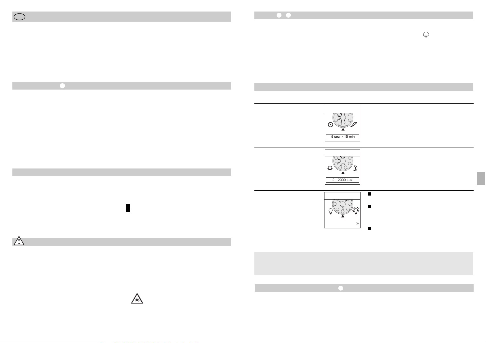
Tesisat –
Lamba taraf›ndan yay›lan ›s›n›n sistemin devreye
girmesine sebep olaca¤›ndan montaj yeri mevcut
bir lambadan en az 50 cm uzakta olmal›d›r. Belirti-
len max. 12 metrelik eriflim mesafelerine eriflebilmek
için montaj yüksekli¤i max. yaklafl›k 2 m olmal›d›r.
Cihaz›n yanl›fl olarak devreye girmesini önlemek için
cihaz› sa¤lam bir zemin üzerine monte edin.
Elektrik kablosu 3 telli kablodan oluflur:
- 55 -
Fonksiyonlar
Kapatma gecikmesi
(Zaman ayar›)
(Fabrika ç›k›fl ayar›: 5 saniye)
5 sn. ile 15 dakika aras›nda kademesiz olarak ayarlanabilen yanma süresi.
Ayar regülatörü 1 (sola dayand›¤›nda) rakam› üzerine
ayarland›¤›nda = en k›sa yanma süresi (5 sn.)
Ayar regülatörü 6 (sa¤a dayand›¤›nda) rakam› üzerine
ayarland›¤›nda = en uzun yanma süresi (15 dak.)
Kapsama alan› ayarlama iflleminde en k›sa sürenin 1
ayarlanmas› tavsiye edilir.
Temel Parlakl›k
(Fabrika ç›k›fl ayar›: Program 1)
Ayarlanm›fl olan alaca karanl›k de¤erinden itibaren
projektör YANAR / temel parlakl›k yok.
Ayarlanm›fl olan alaca karanl›k de¤erinden itibaren
hareket alg›lamas›nda projektör YANAR / + ayarlanm›fl olan süre dolduktan sonra yaklafl›k 10 dakika için temel parlakl›k (%10).
Lamba, ayarlanm›fl olan alaca karanl›k de¤erinden / + temel parlakl›k (%10) itibaren bütün
gece boyunca YANAR.
Alaca karanl›k ayar›
(devreye girme s›n›r›)
(Fabrika ç›k›fl ayar›:
Gündüz ›fl›k iflletmesi 2000 Lux)
Sensörün 2 – 2000 Lux aras›nda kademesiz olarak
ayarlanabilen devreye girme s›n›r›.
Ayar regülatörü 1 rakam›na (sola dayand›¤›nda)
ayarland›¤›nda = Gündüz ›fl›k iflletmesi (yakl. 2000 Lux).
Ayar regülatörü 6 rakam›na (sa¤a dayand›¤›nda) ayarland›¤›nda = Alaca karanl›k iflletmesi yakl. 2 Lux.
Kapsama alan› ayar› gündüz yap›ld›¤›nda ayar regülatörü 1 (gündüz ›fl›k iflletmesi) konumuna getirilecektir.
LED 10% OFF / 10 min. / ~
1
2
Tüm fonksiyonlar ring blendaj› söküldü¤ünde
ayarlanabilir.
Temel parlakl›¤›n anlam› ?
Temel ayd›nlatma, yaklafl›k % 10 ›fl›k kapasitesi ile
sürekli ayd›nlatma demektir. Ancak kapsama alan›nda
bir hareket alg›land›¤›nda ›fl›k (ayarlanm›fl olan kapat-
ma gecikme süresi boyunca ) azami ›fl›k kapasitesinde (%100) yanar. Bu süre dolduktan sonra lamba
tekrar temel ayd›nlatma (yaklafl›k %10) moduna geçer.
Eriflim Mesafesi Ayar›/Ayarlama
Kapsama alan› gereklili¤e göre optimize edilebilir.
Cihaz ile birlikte gönderilmifl olan kapaklar birden fazla
mercek seksiyonunun kapat›lmas›n› ve böylece eriflim
mesafesinin gereklili¤e göre k›salt›lmas›na yarar. Bu
flekilde örne¤in otomobil, yayalar vs. gibi objelerin
meydana getirdi¤i hatal› kumandalama ortadan kald›r›l›r veya tehlike bölümleri tam istenildi¤i gibi denetlenebilir. Kapaklar, oluklar› aç›lm›fl bölmeler boyuna
dikey ve yatay k›s›mdan ayr›labilir veya makas ile
kesilebilir. Ring kapa¤›n›n ç›kar›lmas›ndan sonra bu
kapaklar sensör merce¤inin üst bölümüne yerlefltirilebilir. Sonra ring kapa¤› tekrar yerine tak›lacak ve böylece örtme kapaklar› sabitlenecektir.
Sensör gövdesini ± 80° döndürerek hassas ayarlama yapma mümkündür.
L = Faz (genellikle siyah veya kahverengi)
N = Nötr iletken (genellikle mavi)
PE = Toprak hatt› (yeflil/sar›)
Önemli: Elektrik kablolar›n›n kar›flt›r›lmas› cihaz içinde
veya sigorta kutusunda k›sa devre oluflmas›na yol
açabilir. Bu durumda kablolar tek tek belirlenecek ve
yeniden monte edilecektir. Elektrik kablosuna AÇMA
ve KAPAMA ifllemini gerçeklefltirmek için uygun bir flalter tak›labilir.
- 54 -
Montaj K›lavuzu
Say›n Müflterimiz,
STEINEL sensörlü LED projektörünü sat›n alarak firmam›z›n ürünlerine göstermifl oldu¤unuz güvenden dolay›
çok teflekkür ederiz. ‹tina ile üretilmifl, test edilmifl ve
ambalajlanm›fl bu ürünü tercih ederek yüksek kaliteli bir
cihaz sat›n alm›fl bulunmaktas›n›z.
TR
Güvenlik Bilgileri
■ Cihaz üzerinde yap›lacak her çal›flmadan önce
gerilim beslemesini kesin!
■ Montaj çal›flmas› esnas›nda ba¤lanacak olan elektrik kablosundan ak›m geçmemelidir. Bu nedenle
önce elektrik ak›m›n› kesin ve sonra kabloda gerilim
olmad›¤›n› voltaj kontrol cihaz› ile kontrol edin.
■ Bu ürünün tesisat çal›flmas› elektrik flebekesi üzerinde yap›lan bir çal›flmad›r; bu nedenle sözkonusu
çal›flma ilgili ülkelerde geçerli olan tesisat yönetmelikleri ve ba¤lama flartlar›na göre yap›lacakt›r
(D-VDE 0100, A-ÖVE/ÖNORM E 8001-1,
-SEV 1000)
Tesisat iflleminden önce lütfen bu Montaj Talimat›n›
okuyun. Tesisat ve iflletmeye alman›n ancak talimatlara
göre yap›lmas› durumunda uzun ömürlü, güvenilir ve
ar›zas›z bir iflletme sa¤lan›r.
STEINEL sensörlü LED projektörü ile iyi çal›flmalar
dileriz.
■
Cihaz› kolay alev alabilir ola¤an yüzeyler üzerine
monte etmeyin.
■ D›fl ve iç mekanlar için uygundur.
■ Sensörlü LED projektörü sadece duvara monte
etmek için tasarlanm›fl olup tavana montaj için
uygun de¤ildir.
■ Projektör aç›kken lamban›n gövdesi ›s›n›r. LED
kafas›n›n ayd›nlatt›¤› alan› ayarlamadan önce
lamban›n so¤umas›n› bekleyin.
■ LED lambas›na k›sa mesafeden veya
uzun süre (> 5 dakika) ile bakmay›n.
Aksi taktirde gözünüzün a¤ tabakas›
zarar görebilir.
Çal›flma Prensibi
Lamba çevresinde tespit edilen bir hareket ›fl›k, alarm
ve daha birçok sistemi devreye al›r. Sizin güvenli¤iniz
ve konforunuz için. Sensörlü LED projektörü ev ve
arsa gibi özel alanlar›n ayd›nlat›lmas›nda kullan›ld›¤›
gibi örne¤in firma sahas›n›n ayd›nlat›lmas› gibi ticari
alanlar›n da ayd›nlat›lmas›nda kullan›lan bu sensörlü
LED projektörü h›zl› ve basit flekilde monte edilir ve
çal›flt›rmaya haz›rd›r.
Sensörlü LED projektörü XLed 10 ve XLed 25 iki adet
120° piro sensörü ile donat›lm›fl olup hareket eden
vücutlar›n (insan, hayvan, vs.) yayd›¤› ›s›y› alg›lar.
Alg›lanan bu ›s› yay›l›m› cihaz içinde elektronik olarak
ifllenir ve ba¤l› olan projektörü çal›flt›r›r. Örne¤in duvar
veya cam gibi engeller bulundu¤unda ›s› yay›lmas›
alg›lanmaz. ‹ki adet piro sensör ile 240°'lik bir kapsama
aç›s› ve 180°'lik bir açma aç›s›na eriflilir.
Önemli: Lambay› yürüyüfl yönünün yan taraf›na do¤ru
monte etti¤inizde veya ayarlad›¤›n›zda ve sensör
önünde herhangi bir engel (örne¤in a¤aç, duvar vs.)
bulunmad›¤›nda hareket alg›lanmas› en do¤ru ve
güvenli flekilde sa¤lan›r.
Cihaz Aç›klamas›
Flat dizaynl› LED kafas›
Mafsall› kol
So¤utma kanatlar›
Güç kayna¤› ile birlikte duvar tutma eleman›
Sensör ünitesi
Conta
Kapatma kapaklar›
Çal›flma Prensibi
Zaman ayar›
Alaca Karanl›k Ayar›
Temel Parlakl›k Ayar›
Eriflim Mesafesi Ayar›/Kapsama Alan› Ayar›
Sürekli Ifl›k Fonksiyonu
S›va alt› flebeke ba¤lant›s› besleme kablosu
S›va üstü elektrik besleme kablosu
I
II
TR
3
Page 29

- 57 -
Fonksiyon Garantisi
Bu STEINEL ürünü yüksek itina ile üretilmifl olup
geçerli olan yönetmeliklere uygun olarak fonksiyon ve
güvenlik testlerinden geçirilmifl ve son olarak numune
kontrolü ifllemleri uygulanm›flt›r. STEINEL firmas› ürünün mükemmel durumda ve fonksiyon özelliklerine
sahip oldu¤unu garanti eder.
Cihaz 36 ay garantilidir ve garanti süresi cihaz›n
al›c›ya sat›ld›¤› günden itibaren bafllar. Firmam›z malzeme ve imalat hatalar›ndan kaynaklanan ar›zalar›
giderir, garanti kapsam›nda verilen bu hizmetler ar›zal›
parçan›n onar›m› veya de¤ifltirilmesi fleklinde yap›l›r
ve bu seçime firmam›z karar verir. Sarf malzemeleri,
yönetmeliklere ayk›r› kullan›m veya bak›mdan kaynaklanan hasar ve eksiklikler garanti kapsam›na dahil
de¤ildir. Bunun d›fl›nda yabanc› eflyalar üzerinde oluflacak müteakip hasarlarda firmam›zdan herhangi bir
hak iddia edilemez.
Garanti hizmetlerinden faydalanmak sadece, cihaz
sökülmeden ve parçalar›na ayr›lmadan, özet ar›za
aç›klamas›, kasa fifli veya fatura (sat›n al›fl tarihini
belirten bayi kaflesi ile) ile iyi flekilde ambalajlanarak
yetkili servis merkezine gönderilmesi ile gerçekleflir.
Tamir servis hizmeti:
Garanti süresi dolduktan sonra
oluflan ar›zalar veya garanti kapsam›nda bulunmayan parçalar›n
hasarlanmas› durumunda fabrika
servisimiz gerekli tamir hizmetlerini
verir. Bunun için lütfen cihaz› iyi
flekilde ambalajlayarak en yak›n
servis merkezimize postalay›n.
Uygunluk Aç›klamas›
Bu ürün Alçak Gerilim Yönetmeli¤i 2006/95/AT ve
EMV Yönetmeli¤i 2004/108/AT ve RoHS direktifi
2002/95/AT maddelerine uygundur .
‹flletme Ar›zalar›
Sensörlü LED projektörüne gerilim
beslemesi yok
Sensörlü LED projektörü devreye
girmiyor
Sensörlü LED projektörü
kapanm›yor
Sensörlü LED projektörü istenmeden devreye giriyor
Ar›za
■ Sigorta ar›zal›, devrede de¤il,
kablo hatt›nda kesiklik
■ K›sa devre
■ Yeni sigorta tak›n, flebeke flal-
terini aç›n; kabloyu voltaj
kontrol cihaz› ile kontrol edin
■ Ba¤lant›lar› kontrol edin
■ Gündüz iflletmesinde alaca
karanl›k ayar› gece iflletmesine
ayarlanm›flt›r
■ Elektrik flalteri KAPALI
■ Sigorta ar›zal›
■ Kapsama alan› tam do¤ru olarak
ayarlanmad›
■ Yeniden ayarlay›n
■ Çal›flt›r›n
■ Yeni sigorta tak›n gerekti¤inde
ba¤lant›y› kontrol edin
■ Yeniden ayarlay›n
■ Kapsama alan› içinde sürekli
hareket alg›lan›yor
■ Alan› kontrol edin ve yeniden
ayarlay›n veya bölümün üzerini
örtün
■ Rüzgar kapsama alan›ndaki
a¤aç ve çal›l›klar› hareket ettiriyor
■ Yoldan geçen otomobiller
alg›lan›yor
■ Hava flartlar› (rüzgar, ya¤mur,
kar) nedeniyle ani s›cakl›k
de¤iflmesi veya vantilatör, aç›k
olan pencerelerden hava ak›m›
geliyor
■ Sensörlü LED projektörü,
örne¤in f›rt›na veya afl›r› ya¤›fl
nedeniyle sallan›yor (hareket
ediyor).
■ Kapsama alan›n› de¤ifltirin
■ Kapsama alan›n› de¤ifltirin
■ Kapsama alan›n› de¤ifltirin,
cihaz› baflka yere monte edin
■ Sensörlü LED projektörünü
sa¤lam bir zemin üzerine monte
edin
Sebebi Tamiri
Sensörlü LED projektörü sürekli
AÇIP/KAPATIYOR
■ Kapsama alan› dahilinde hayvanlar hareket etmektedir
■ Sensörü yukar›ya çevirin
veya hareketleri alg›lamayacak
flekilde üzerini örtün; Kapsama
alan›n› de¤ifltirin, veya üzerini
örtün
- 56 -
Çal›flt›rma ve Bak›m
Öngörülen sabotaj emniyeti bu cihazda bulunmad›¤›ndan projektör, özel h›rs›zl›k alarm sistemleri için uygun
de¤ildir. Hava flartlar› sensörlü LED projektörünün
fonksiyonunu etkileyebilir. Kuvvetli rüzgar, kar, ya¤mur, dolu durumlar› ani s›cakl›k de¤iflmesi oluflturdu-
¤undan ve cihaz›n bu durumu ›s› kayna¤›ndan ay›rt
edememesi lamban›n hatal› olarak devreye girmesine
sebep olabilir.
Kapsama merce¤i kirlendi¤inde nemli bir bezle (temizleme maddesi kulan›lmadan) silinerek temizlenebilir.
Sürekli Ifl›k Fonksiyonu
Bir flebeke flalteri elektrik besleme hatt›na ba¤land›¤›nda basit açma ve kapama fonksiyonlar›n›n d›fl›nda
afla¤›da aç›klanan fonksiyonlar da mümkündür:
Sensör iflletmesi
1) Ifl›¤› açma (projektör KAPALI oldu¤unda):
fialter 1 x KAPALI ve AÇIK pozisyona getirilecek.
LED lambalar›, ayarlanan süre boyunca yanar.
2) Ifl›¤› kapatma (projektör AÇIK oldu¤unda):
fialter 1 x KAPALI ve AÇIK pozisyona getirilecek.
Projektör kapat›l›r veya sensör iflletme moduna geçer.
Sürekli ›fl›k iflletmesi
1) Sürekli ›fl›¤› açma:
fialter 2 x KAPALI ve AÇIK pozisyona getirilecek. Projektör 4 saat boyunca sürekli ›fl›k iflletmesine ayarlan›r
(merce¤in arkas›ndaki k›rm›z› LED lambas› yanar). Bu
süre dolduktan sonra otomatik olarak tekrar sensör
iflletmesine geçer (k›rm›z› LED lambas› söner).
2) Sürekli ›fl›¤› kapatma:
fialter 1 x KAPALI ve AÇIK pozisyona getirilecek.
Projektör kapat›l›r veya sensör iflletme moduna geçer.
Önemli:
fialtere birden fazla kez basma h›zl› flekilde
yap›lmal›d›r ( 0,5 – 1 sn. aral›¤›nda.).
Teknik Özellikler
Sensörlü LED projektörü XLed 10 XLed 25
Güç: 10 LED, yakl. 25 W 25 LED, yakl. 60 W
Ifl›k rengi: yaklafl›k 4000 Kelvin (sar›) yaklafl›k 4000 Kelvin (sar›)
Ifl›k ak›m›: 960 Lümen 2120 Lümen
Ek kumanda gücü:
Ampuller, max. 800 W, 230 V AC
Fluoresan lamba, max. 400 W, cos ϕ = 0,5,
indüktif yük 230 V AC
Fluoresan lambalar, enerji tasarruf lambalar›,
Elektronik ön kumanda cihazl› 230 V AC LED lambalar›,
4 x her biri max. 60 W, C ≤ 88 μF
LED kullan›m ömrü: 50.000 saate kadar 50.000 saate kadar
(3 Saat/Gün kullan›ld›¤›nda (3 Saat/Gün kullan›ld›¤›nda
yakl. 45 y›l) yakl. 45 y›l)
Kapsama aç›s›: 240° alttan geçme korumal›, 240° alttan geçme korumal›,
açma aç›s› açma aç›s›
Projeksiyon alan› 250 cm2+ 103,36 cm
2
420 cm2+ 103,36 cm
2
Sensör ünitesi
döndürme aral›¤›: ± 80° ± 80°
Gövde döndürme aral›¤›: dikey 200° dikey 200°
yatay 270° yatay 270°
Zaman ayar›: 5 sn. – 15 dak. 5 sn. – 15 dak.
Alaca karanl›k ayar›: 2 – 2000 Lux 2 – 2000 Lux
Parlakl›k ayar›: %10 Temel parlakl›k (yakl. 3 W) %10 Temel parlakl›k (yakl. 6 W)
Sürekli ›fl›k: 4 saat ayarlanabilir 4 saat ayarlanabilir
Boyutlar (Y x G x D) 205 x 200 x 220 mm 300 x 200 x 220 mm
A¤›rl›k: 2200 gr. 2960 gr.
S›cakl›k aral›¤›: -20 °C ile +50 °C aras› -20 °C ile +50 °C aras›
Koruma türü: IP 44 IP 44
Koruma s›n›f›: I I
TR
Page 30
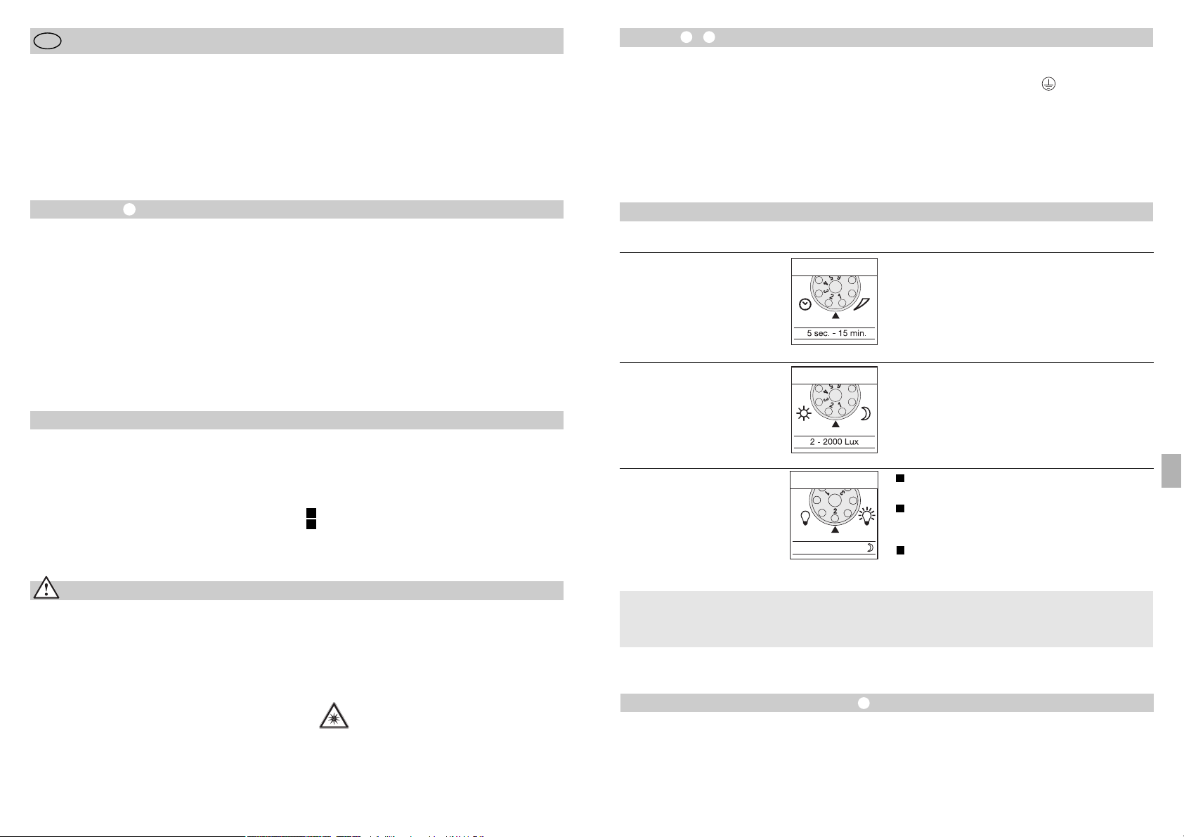
Bekötés –
A lámpát más fényforrásoktól legalább 50 cm-re
kell felszerelni, mert azok hősugárzása téves jelzést
okozhat. A megadott max. 12 m-es hatótávolság
eléréséhez a szerelési magasság kb. 2 m legyen.
A berendezést szilárd alapra szerelje fel, a téves
bekapcsolások megelőzésének érdekében.
A hálózati kábel háromeres vezeték:
- 59 -
Funkciók
Kikapcsolás késleltetés
(időbeállítás)
(a gyári beállítás: 5 mp.)
A világítási idő fokozatmentesen állítható 5 mp-től
15 percig.
A szabályzót az 1-es számra (bal oldali ütközésig)
állítva = a legrövidebb idő (5 mp.),
A szabályzót az 6-os számra (jobb oldali ütközésig)
állítva = a leghosszabb idő (15 perc),
Az érzékelési tartomány beállításakor ajánlott a
legrövidebb időt (1) beállítani.
Alapfényerő
(gyári beállítás: 1. program)
A fényszóró mozgás esetén BE kapcsol a beállított
fényerő-értéknél / nincs alapfényerő.
A fényszóró mozgás esetén BE kapcsol a beállított
fényerő-értéknél / + alapfényerővel (10%) világít
10 percig a beállított idő lejárta után.
A fényszóró mozgás esetén BE kapcsol a beállított
fényerő-értéknél / + alapfényerővel (10%) világít
egész éjszaka.
Alkonykapcsoló-beállítás
(érzékenységi küszöb)
(gyári beállítás:
nappali üzem, 2000 Lux)
Az érzékelő érzékelési küszöbe fokozatmentesen
állítható 2 – 2000 Lux között.
A szabályzót az 1-es számra állítva (balra forgatva) =
nappali üzem, kb. 2000 lux.
A szabályzót a 6-os számra állítva (balra forgatva) =
alkony-üzemmód, kb. 2 Lux.
Az érzékelési tartomány beállításánál nappali fénynél
a szabályzó gombot állítsa az 1-re (nappali üzem)!
LED 10% OFF / 10 min. / ~
1
2
A különböző funkciók a takarógyűrű lehúzása után
állíthatók be.
Mi az alapfényerő?
Az alapfényerő kb. 10 %-os fényerővel történő megvilágítást tesz lehetővé. A lámpa csak az érzékelési
tartományban történő mozgás esetén (a beállított
időtartamra, ld. Kikapcsolás-késleltetés ) a maximális fényerőre (100 %) kapcsol be. Ezután a lámpa
10 percre ismét az alapfényerőre (10 %) kapcsol.
Hatótávolság beállítás/finombeállítás
Az érzékelési terület kívánság szerint pontosan beállítható. A mellékelt takaróbetétek szolgálnak arra, hogy
a lencse kívánt számú szegmensét letakarhassa, ill.
a hatótávolságot egyéni igényei szerint lerövidíthesse.
Ezáltal pl. az autók, gyalogosok által kiváltott téves
riasztások kizárhatók, vagy veszélyes területek célzottan megfigyelhetők. A takaróbetétek a bemélyített
hornyok mentén függőleges és vízszintes irányban
szétválaszthatók, vagy ollóval vághatók. A takarógyűrű levétele után a lencse legfelső mélyedésébe
beakaszthatók. A takarógyűrűt ezután ismét helyezze
fel, miáltal a takaróbetéteket szilárdan rögzíti a helyükön. Az érzékelő házának forgatásával ± 80° mértékben ezen felül finombeállítás is lehetséges.
L = fázis (többnyire fekete vagy barna)
N = nulla vezeték (többnyire kék)
PE = védőföldelés (zöld/sárga)
Fontos: A csatlakozók felcserélése a berendezésben
vagy a biztosítéktáblán később rövidzárlathoz vezet.
Ebben az esetben ismét azonosítsa az egyes kábeleket és csatlakoztassa azokat újra. A hálózati vezetékben elhelyezhető egy megfelelő hálózati kapcsoló a
berendezés BE- és KIkapcsolásához.
- 58 -
Szerelési utasítás
Igen tisztelt Ügyfelünk!
Köszönjük bizalmát, amit új STEINEL belső mozgásérzékelős LED-es fényszórójának megvásárlásával
kifejezésre juttatott. Ön egy kiváló minőségű termék
mellett döntött, amelyet a legnagyobb gondossággal
gyártottunk, próbáltunk ki és csomagoltunk.
H
Biztonsági tudnivalók
■ A berendezésen végzett minden munka előtt
gondoskodjon a feszültségmentesítésről!
■ Szereléskor a csatlakoztatni kívánt vezetéknek
feszültségmentesnek kell lennie. Ezért a szerelés
megkezdése előtt kapcsolja le az áramot, és
feszültség-ellenőrző segítségével ellenőrizze
a feszültségmentességet!
■ A berendezés felszerelésekor hálózati feszültséggel
végzett munkálatokról van szó; ezért azt szakszerűen, a szokásos szerelési előírásoknak és csatlakoztatási feltételeknek megfelelően kell elvégezni
(D-VDE 0100, A-ÖVE/ÖNORM E 8001-1,
-SEV 1000).
Kérjük, az üzembe helyezés előtt tanulmányozza át
alaposan ezt a használati útmutatót. Csak a szakszerű felszerelés és üzembehelyezés garantálja a
hosszú távú, megbízható és zavarmentes működést.
Kívánjuk, hogy új STEINEL mozgásérzékelős LED-es
fényszórójának használatában örömét lelje.
■
Ne szerelje a berendezést általában gyúlékony
felületekre!
■ Kül- és beltéri használatra egyaránt alkalmas.
■ A mozgásérzékelős LED-es fényszóró csak falra
való felszerelésre alkalmas, mennyezetre nem.
■ A fényszóróház működés közben erősen felmelegszik. A fényszóró LED-fejének beállítását csak
hideg állapotban végezze.
■ Ne nézzen közelről vagy huzamosabb ideig
(> 5 perc) a LED-fényszóróba. Ez a
kötőhártya sérülését okozhatja.
Működési elv
A mozgás bekapcsolja a világítást, a riasztót és sok
minden mást az Ön kényelme és biztonsága érdekében. Akár magán célra, a ház és a kert megvilágításához, akár üzleti célú felhasználásra, pl. a cég telephelyének megvilágítására, ezek a mozgásérzékelős LEDes fényszórók mindenütt gyorsan felszerelhetők és
üzembe helyezhetők.
Az XLed 10 és XLed 25 mozgásérzékelős LED-es
fényszórók két, 120°-os pyro-szenzorral rendelkeznek,
melyek a mozgó testek (emberek, állatok stb.) láthatatlan hősugárzását érzékelik. A berendezés a felfo-
gott hősugárzást elektronikus jellé alakítja, és ennek
segítségével kapcsolja a fényszórót. Akadályokon, pl.
falon vagy ablaküvegen keresztül a hősugárzás nem
érzékelhető. A két pyro-szenzor segítségével 240°-os
érzékelési szög és 180°-os nyitási szög érhető el.
Fontos: A mozgás érzékelése akkor a legbiztosabb,
ha a berendezést a mozgáshoz képest oldalirányban
helyezi el, és az érzékelő látóterét nem korlátozzák
akadályok (pl. fák, falak stb.).
Készülékismertetés
Lapos LED-fej
Csuklós kar
Hűtőbordák
Falitartó hálózati egységgel
Érzékelő egység
Tömítődugó
Takaróbetét
Működési elv
Időbeállítás
Alkonykapcsoló-beállítás
Alapfényerő beállítása
Hatótávolság-beállítás / Érzékelési tartomány
finombeállítás
Tartós világítás funkció
Hálózati csatlakozás vakolat alatti vezetékezéshez
Hálózati csatlakozás vakolat feletti vezetékezéshez
I
II
H
3
Page 31

- 61 -
Működési garancia
Ezt a STEINEL terméket a legnagyobb gonddal készítették, működését és biztonságát az érvényes előírásoknak megfelelően ellenőrizték, majd szúrópróba
során tesztelték. A STEINEL garanciát vállal a kifogástalan minőségre és működésre.
A garancia ideje 36 hónap, ami a vásárlás napján kezdődik. Minden olyan hibát kijavítunk, ami anyag- vagy
gyártási hibára vezethető vissza. A garancia teljesítésének módját mi választjuk meg: ez lehet a hibás rész
javítása vagy cseréje. Nem vállalunk garanciát kopásnak kitett alkatrészekre és olyan károsodásokra, amit
szakszerűtlen kezelés vagy karbantartás okozott. Más
tárgyakra következményként átterjedő károk a garanciából ki vannak zárva.
A garanciát csak akkor vállaljuk, ha a készüléket
szétszereletlen állapotban, a hiba rövid leírásával,
pénztárbizonylattal vagy számlával (vétel időpontjával,
kereskedő pecsétjével) együtt, szakszerűen becsomagolva az illetékes szervizállomásra küldték.
Javítási szolgáltatás:
A garanciaidő eltelte után, vagy nem
garanciás esetekben gyári szervizünk
elvégzi a javításokat. Kérjük, hogy a
terméket szakszerűen becsomagolva
küldje a legközelebbi szervizbe.
Megfelelési tanúsítvány
Ez a termék megfelel a 2006/95/EG kisfeszültségre
vonatkozó, és a 2004/108 EMV-, valamint a
2002/95/EG RoHS-irányelveinek.
Működési zavarok
A mozgásérzékelős LED-es
fényszóró nem kap feszültséget
A mozgásérzékelős LED-es
fényszóró nem kapcsol be
A mozgásérzékelős LED-es
fényszóró nem kapcsol ki
A mozgásérzékelős LED-es
fényszóró szükségtelenül
bekapcsol
Üzemzavar
■ a biztosíték meghibásodott,
nincs bekapcsolva, a vezeték
megszakadt
■ rövidzárlat
■ új biztosíték, hálózati kapcsolót
bekapcsolni; vezetéket feszültségvizsgálóval ellenőrizni
■ csatlakozókat ellenőrizni
■ nappali üzemnél, az akony-
kapcsoló éjszakai állásban van
■ a hálózati kapcsoló KI van
kapcsolva
■ a biztosíték meghibásodott
■ az érzékelési tartomány nincs
célzottan beállítva
■ újra beállítani
■ bekapcsolni
■ új biztosíték, esetleg a
csatlakozót ellenőrizni
■ újra beállítani
■ folyamatos mozgás az érzékelési
tartományban
■ ellenőrizze az érzékelési
tartományt és szükség
esetén állítsa be újra
ill. takarja ki
■ a szél fákat és bokrokat mozgat
az érzékelési tartományban
■ az utcán haladó autókat érzékeli
■ hirtelen hőmérsékletváltozás az
időjárás miatt (szél, eső, hó)
vagy a ventilátorokból, nyitott
ablakokon át kiáramló levegő
miatt.
■ A mozgásérzékelős LED-es
fényszóró kitér (mozog)
pl. széllökések, vagy erős
csapadék miatt.
■ módosítsa az érzékelési területet
■ módosítsa az érzékelési területet
■ a tartományt módosítani, más
felszerelési helyet választani
■ Szerelje a mozgásérzékelős
LED-es fényszórót szilárd alapra
Ok Elhárítás
A mozgásérzékelős LED-es
fényszóró mindig KI/BE kapcsol
■ állatok mozognak az érzékelési
tartományban
■ helyezze az érzékelőt
magasabbra, fordítsa el,
ill. célzottan takarja le;
érzékelési tartományt
átállítani, ill. letakarni
- 60 -
Üzemeltetés és ápolás
Speciális riasztóberendezésekben való használatra
a berendezés nem alkalmas, mert az ezek esetében
előírt szabotázsvédelemmel nem rendelkezik. A mozgásérzékelős LED-fényszóró működését az időjárási
körülmények befolyásolhatják.Erős széllökések, hóe-
sés, eső, jégeső esetén téves kapcsolás történhet,
mivel a hirtelen hőmérséklet-ingadozásokat a készülék a hőforrásoktól nem tudja megkülönböztetni.
Az érzékelő lencséje szennyeződés esetén nedves
ruhával (tisztítószer nélkül) tisztítható meg.
Folyamatos világítási funkció
Ha a hálózati vezetékbe kapcsolót iktat, az egyszerű
be- és kikapcsoláson kívül a következő funkciók
válnak lehetségessé:
Érzékelő üzemmód
1) Világítást bekapcsolni (ha a fényszóró KI van
kapcsolva):
A kapcsolót 1 x KI és BE kapcsolni.
A LED-ek a kívánt időre bekapcsolva maradnak.
2) Világítást kikapcsolni (ha a fényszóró BE van
kapcsolva):
A kapcsolót 1 x KI és BE kapcsolni.
A fényszóró kikapcsol, ill. érzékelős üzemre kapcsol.
Folyamatos világítás
1) Állandó világítás bekapcsolása:
A kapcsolót 2 x KI és BE kapcsolni. A fényszóró
4 órára folyamatos üzembe kapcsol (a piros LED a
lencse mögött világít).Ezután automatikusan ismét
érzékelős üzemre kapcsol (a piros LED elalszik)
2) Állandó világítás kikapcsolása:
A kapcsolót 1 x KI és BE kapcsolni. A fényszóró
kikapcsol, ill. érzékelős üzemre kapcsol.
Fontos:
A kapcsoló többször egymás utáni működtetését gyorsan kell végezni ( 0,5 – 1 mp. közötti tartományban).
Műszaki adatok
Mozgásérzékelős
LED-es fényszóró XLed 10 XLed 25
Teljesítmény: 10 LED, kb. 25 W 25 LED, kb. 60 W
Fényhőmérséklet: kb. 4000 Kelvin (melegfehér) kb. 4000 Kelvin (melegfehér)
Fényáram: 960 lumen 2120 lumen
Kiegészítő kapcsolt teljesítmény:
Izzólámpák, max. 800 W, 230 V váltóáram esetén
Fénycsövek, max. 400 W, cos ϕ = 0,5-nél,
induktív terhelés 230 V váltóáram esetén
Fénycsövek, energiatakarékos lámpák,
LED-lámpák elektronikus előtéttel, 230 V váltóáram esetén,
4 x max. egyenként 60 W, C ≤ 88 µF
A LED-ek élettartama: 50.000 óráig 50.000 óráig
(3 óra./nap esetén kb. 45 év) (3 óra./nap esetén kb. 45 év)
Érzékelési szög: 240° alákúszás-védelemmel 240° alákúszás-védelemmel
Vetített felület: 250 cm2+ 103,36 cm
2
420 cm2+ 103,36 cm
2
Az érzékelő egység
állítási tartománya: ± 80° ± 80°
A ház állítási tartománya: függőlegesen 200° függőlegesen 200°
vízszintesen 270° vízszintesen 270°
Időtartam-beállítás: 5 mp. – 15 perc 5 mp. – 15 perc
Alkonykapcsoló-beállítás: 2 – 2000 Lux 2 – 2000 Lux
Fényerőszabályozás: 10% alapfényerő (kb. 3 W) 10% alapfényerő (kb. 6 W)
Folyamatos világítás: 4 óra beállítható 4 óra beállítható
Méretek (M x Sz x M): 205 x 200 x 220 mm 300 x 200 x 220 mm
Tömeg: 2200 g 2960 g
Hőmérséklet-tartomány: -20 °C bis +50 °C -20 °C bis +50 °C
A védelem fajtája: IP 44 IP 44
Védettségi fokozat: I I
H
Page 32
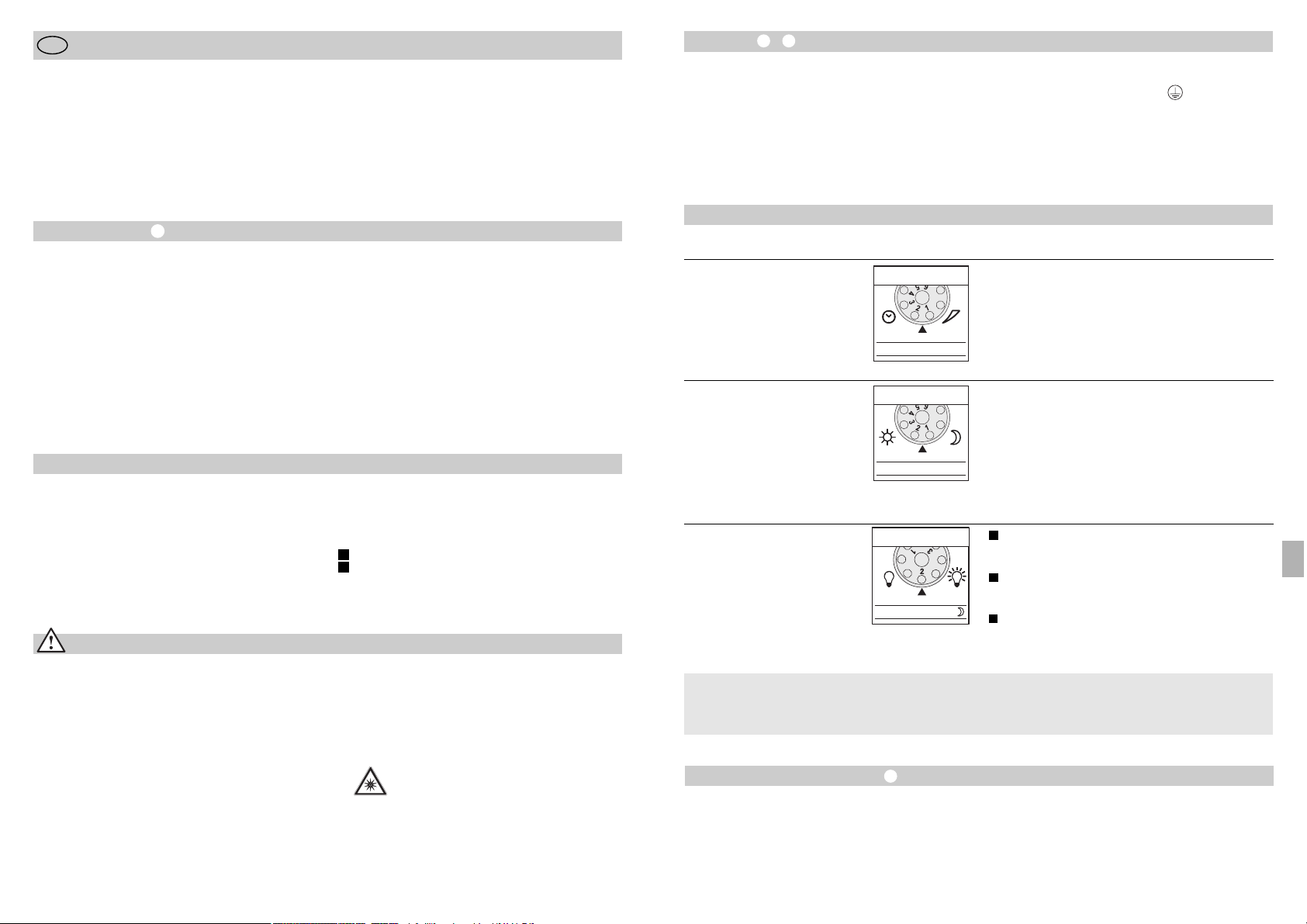
Instalace –
Místo montáže by mělo být od jiného svítidla vzdáleno nejméně 50 cm, poněvadž tepelné záření může
mít za následek spuštění systému. Aby bylo možno
dosáhnout uvedeného dosahu max. 12 m, měla by
montážní výška činit asi 2 m. K vyloučení chybných
zapnutí namontujte přístroj na pevný podklad.
K připojení k elektrické síti použijte třípólový kabel.
- 63 -
Funkce
Zpoždění vypnutí
(časové nastavení)
(nastavení z výroby: 5 s)
Doba, po kterou má lampa svítit, je plynule nastavitelná
v rozmezí 5 s až 15 min.
Otočný regulátor nastavený na 1 (levý doraz) =
nejkratší doba (5 s)
Otočný regulátor nastavený na 6 (pravý doraz) =
nejdelší doba (15 min.)
Při nastavování oblasti záchytu se doporučuje zvolit
nejkratší dobu 1.
Základní jas
(nastavení z výroby: program 1)
Reflektor se při pohybu zapne od nastavené
hodnoty soumrakového nastavení / bez základního
jasu.
Reflektor se při pohybu zapne od nastavené
hodnoty soumrakového nastavení / + základního
jasu (10%) na 10 min. po uplynutí nastavené doby.
Reflektor se při pohybu od nastavené soumrakové
hodnoty / + základního jasu (10%) rozsvěcuje po
celou noc.
Soumrakové nastavení
(prahová reakční doba)
(nastavení z výroby:
provoz za denního světla 2000 lx)
Prahovou reakční hodnotu senzoru je možno nastavovat plynule v rozmezí od 2 do 2000 lx.
Otočný regulátor nastavený na 1 (levý doraz) =
provoz za denního světla asi 2000 lx.
Otočný regulátor nastavený na 6 (pravý doraz) =
soumrakový provoz asi 2 lx.
K nastavení oblasti záchytu za denního světla je třeba
nastavit otočný regulátor na 1 (provoz za denního
světla).
LED 10% OFF / 10 min. / ~
1
2
3
Všechny funkce lze nastavit po sejmutí
prstencové clony.
Co je to základní jas ?
Základní jas umožňuje osvětlení se světelným výkonem přibližně 10 %. Teprve při pohybu v oblasti
záchytu bude světlo (po nastavenou dobu, viz
zpoždění vypnutí ) sepnuto na maximální světelný
výkon (100 %). Poté se svítidlo na 10 minut zase
přepne na základní jas (asi 10 %).
Nastavení / seřízení dosahu
Oblast záchytu je možno nastavit tak, aby byla optimálně přizpůsobena konkrétní potřebě. Přiložené krycí clony slouží k zakrytí libovolného počtu segmentů
čočky a případně i k individuálnímu zkrácení dosahu.
Tím se zajistí vyloučení chybných zapnutí, např.
v důsledku průjezdu automobilů, pohybu kolemjdoucích
atd., případně cílené sledování nebezpečných míst.
Jednotlivé krycí clony lze oddělit nebo odstřihnout
nůžkami - ve vodorovném i svislém směru - podél
předem vyražených dělicích drážek. Po sejmutí
prstencové clony se krycí clony zavěsí v horní oblasti
čočky senzoru. Nasazením prstencové clony do
původní polohy se pak krycí clony pevně zajistí.
Natočením tělesa senzoru v rozsahu ± 80° je navíc
možno provést jemné doladění.
L = fázový vodič (většinou černý nebo hnědý)
N = neutrální vodič (většinou modrý)
PE = ochranný vodič (zelenožlutý)
Důležité: Záměna vodičů později způsobí zkrat
v přístroji nebo ve vaší pojistkové skříni. V tomto
případě je nutno jednotlivé kabely identifikovat
a poté znovu zapojit. V přívodním síťovém vedení
může být zařazen vhodný síťový vypínač.
5 s – 15 min.
2 – 2000 lx
- 62 -
Montážní návod
Vážený zákazníku,
děkujeme vám za důvěru, kterou jste nám projevil
zakoupením svého nového senzorového reflektoru
LED značky STEINEL. Rozhodl jste se pro vysoce
kvalitní produkt, který byl vyroben, testován a zabalen
s největší možnou pečlivostí.
CZ
Bezpečnostní pokyny
■ Před zahájením jakýchkoli prací na přístroji je nutno
přerušit přívod napětí!
■ Připojované elektrické vedení nesmí být během
montáže pod napětím. Proto je nejprve třeba
vypnout proud a poté pomocí zkoušečky napětí
zkontrolovat, zda je vedení bez napětí.
■ Při instalaci těchto přístrojů se jedná o práci na
síťovém napětí; musí proto být provedena odborně
podle zemských předpisů pro instalaci elektrických
zařízení a podmínek jejich připojení dle ČSN
(D-VDE 0100, A-ÖVE/ÖNORM E 8001-1,
-SEV 1000).
Před instalací se, prosím, seznamte s tímto montážním návodem. Pouze odborně provedená instalace
a zprovoznění totiž zaručí dlouhý, spolehlivý a bezporuchový provoz.
Přejeme vám, abyste byl s novým senzorovým reflektorem LED značky STEINEL naprosto spokojen.
■
K montáži přístroje vybírejte povrchy, které obecně
nepatří mezi snadno vznítitelné.
■ Je vhodný do venkovních a vnitřních prostor.
■ Senzorový reflektor LED je vhodný jen k montáži
na stěnu, není určen k montáži na strop.
■ Těleso reflektoru se během provozu zahřívá. Případné vyrovnání hlavy LED tedy lze provést
až po jejím vychladnutí.
■ Do kontrolky LED se nedívat z krátké
vzdálenosti nebo po delší dobu (> 5 min.).
Mohlo by dojít k poškození sítnice v oku.
Princip činnosti
Pohyb zapíná světlo, výstražný systém a řadu dalších
zařízení. Pro vaše pohodlí, pro vaši bezpečnost. Je
jedno, zda budou použity pro soukromé účely k
osvětlení domu a pozemku, nebo pro komerční účely
k osvětlení např. firemního pozemku, tyto senzorové
reflektory LED lze rychle a pohotově namontovat
všude.
Senzorové reflektory LED XLed 10 a XLed 25 jsou
vybaveny dvěma pyroelektrickými senzory uspořádanými po 120°, které zaznamenávají neviditelné
tepelné záření vydávané pohybujícími se těly (osob,
zvířat atp.). Takto zaznamenané tepelné záření je pak
elektronicky převáděno na signál, který zapíná reflektor. Tepelné záření neprochází překážkami, jakými jsou
například zdi nebo skleněné tabule. Pomocí dvou
pyroelektrických senzorů je při úhlu otevření 180°
dosahováno úhlu záchytu 240°.
Důležité: Nejbezpečnějšího zachycení pohybu dosáhnete tehdy, pokud přístroj namontujete napříč ke
směru chůze a senzoru přitom nebrání ve výhledu
žádné překážky (jako např. stromy, zdi atp.).
Popis přístroje
Plochá hlava LED
Kloubové rameno
Chladicí žebra
Nástěnný držák s napájecí částí
Senzorová jednotka
Utěsňovací zátka
Krycí clony
Princip činnosti
Časové nastavení
Soumrakové nastavení
Nastavení základního jasu
Nastavení dosahu/oblasti záchytu
Funkce trvalého osvětlení
Síťové přívodní vedení pod omítku
Síťové přívodní vedení na omítku
I
II
CZ
Page 33
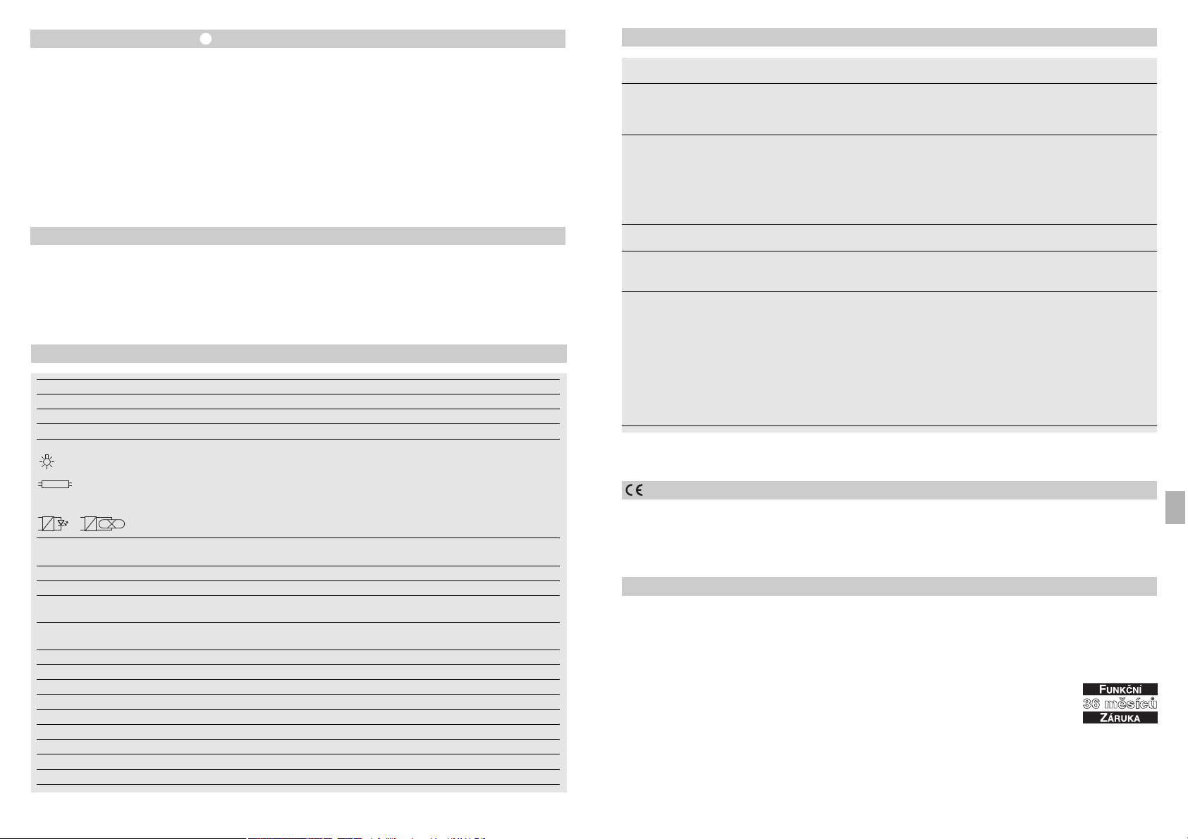
- 65 -
Záruka za funkčnost
Tento výrobek firmy STEINEL je vyráběn s maximální
pozorností věnovanou jeho funkčnosti a bezpečnosti,
které byly vyzkoušeny podle platných předpisů, přičemž se výrobek rovněž podrobil namátkové výstupní
kontrole. Firma STEINEL přebírá záruku za bezvadné
provedení a funkčnost.
Záruka se poskytuje v délce 36 měsíců a začíná
dnem prodeje výrobku spotřebiteli. Odstraněny vám
budou výrobní vady a závady zapříčiněné vadným
materiálem, přičemž záruka spočívá v opravě nebo
výměně výrobku dle rozhodnutí servisu. Záruka se
nevztahuje na vady a škody na dílech podléhajících
opotřebení, na škody zapříčiněné nesprávným zacházením nebo údržbou ani na rozbití způsobené pádem.
Uplatňování dalších nároků následných škod na cizích
věcech je vyloučeno.
Záruka bude uznána jen tehdy, bude-li nedemontovaný přístroj dobře zabalen, přiložen krátký popis závady, pokladní stvrzenka nebo faktura (datum prodeje
a razítko prodejny), poslán na adresu příslušného
servisu.
Servisní opravny:
Naše servisní opravny provádějí rovněž opravy po uplynutí záruční doby
nebo opravy závad, na které se záruka nevztahuje. Dobře zabalený výrobek zašlete, prosím, i v tomto případě nejbližšímu
servisnímu středisku.
Prohlášení o shodě
Tento výrobek splňuje směrnici pro nízké napětí
2006/95/ES směrnici EMV (elektromagnetické snášenlivosti) 2004/108/ES i směrnici RoHS 2002/95/ES.
Provozní poruchy
Senzorový reflektor LED bez napětí
Senzorový reflektor LED nezapíná
Senzorový reflektor LED nevypíná
Senzorový reflektor LED zapíná
v nevhodnou dobu
Porucha
■ Vadná pojistka, lampa není
zapnuta, přerušené vedení
■ Zkrat
■ Nová pojistka, zapnout síťový
vypínač; zkontrolovat vedení
pomocí zkoušečky napětí
■ Zkontrolovat připojení
■ Při denním provozu je zvoleno
soumrakové nastavení odpovídající nočnímu provozu
■ Síťový vypínač v poloze vypnuto
■ Vadná pojistka
■ Oblast záchytu není přesně
nastavena
■ Znovu nastavit
■ Zapnout
■ Nová pojistka, popř. zkontrolovat
připojení
■ Znovu seřídit
■ Trvalý pohyb v oblasti záchytu ■ Zkontrolovat oblast a případně
znovu seřídit nebo zakrýt
■ Vítr pohybuje stromy a keři
v oblasti záchytu
■ Zaznamenávání pohybu aut
na ulici
■ Náhlá změna teploty způsobená
povětrnostními vlivy (vítr, déšť,
sníh) nebo odvětrávaným vzduchem proudícím od ventilátorů
či z otevřených oken
■ Senzorový reflektor LED se
natáčí (pohybuje se), např. při
poryvech větru nebo silném dešti
■ Přestavit oblast záchytu
■ Přestavit oblast záchytu
■ Změnit oblast záchytu,
změnit místo montáže
■ Senzorový reflektor LED
namontovat na pevný podklad
Příčina Náprava
Senzorový reflektor LED střídavě
zapíná a vypíná
■ V oblasti záchytu se pohybují
zvířata
■ Natočit senzor výše popř.
vhodně zakrýt; přestavit oblast
popř. zakrýt její část
- 64 -
Provoz a ošetřování
Přístroj není vhodný pro speciální poplašné soustavy
proti vloupání, protože není vybaven příslušným předepsaným zabezpečením proti sabotáži. Funkci senzorového reflektoru LED mohou ovlivňovat povětrnostní podmínky. Při silných poryvech větru, sněžení,
dešti nebo krupobití může dojít k chybnému zapnutí,
poněvadž náhlé výkyvy teploty nemohou být odlišeny
od účinku skutečných zdrojů tepla.
Snímací čočku je v případě znečištění možno očistit
vlhkým hadříkem (bez použití čisticích prostředků).
Funkce trvalého osvětlení
Je-li v přívodním síťovém vedení zařazen síťový vypínač,
jsou vedle jednoduchého zapínání a vypínání možné
i následující funkce:
Senzorový provoz
1) Zapnutí světla (je-li reflektor vypnutý):
Vypínač 1 x vyp. a zap.
LED zůstanou po nastavenou dobu zapnuté.
2) Vypnutí světla (je-li reflektor zapnutý):
Vypínač 1 x vyp. a zap.
Reflektor zhasne popř. přejde do senzorového provozu.
Trvalý provoz
1) Zapnutí trvalého osvětlení:
Vypínač 2 x vypnout a zapnout. Reflektor se na 4 hodiny přepne na trvalý provoz (červená světelná dioda za
čočkou svítí). Poté opět automaticky přejde do senzorového provozu (červená světelná dioda zhasne).
2) Vypnutí trvalého osvětlení:
Vypínač 1 x vyp. a zap. Reflektor zhasne popř. přejde
do senzorového provozu.
Důležité:
Několikeré stisknutí vypínače by se mělo dít rychle za
sebou (v rozmezí 0,5 – 1 s).
Technická data
Senzorový reflektor LED XLed 10 XLed 25
Výkon: 10 LED, asi 25 W 25 LED, asi 60 W
Barva světla: asi 4000 kelvina (teplá bílá) asi 4000 kelvina (teplá bílá)
Světelný tok: 960 lm 2120 lm
Doplňkový spínaný výkon:
Žárovky, max. 800 W při 230 V AC
Zářivka, max. 400 W při cos ϕ = 0,5,
induktivní zatížení při 230 V AC
Zářivky, úsporné žárovky,
lampy LED s elektronickým předřadným zařízením při 230 V AC,
4 x max. po 60 W, C ≤ 88 µF
Životnost LED: až 50.000 hod. až 50.000 hod.
(u 3 hod./den asi 45 let) (u 3 hod./den přibližně 45 let)
Úhel záchytu: 240° s ochranou proti podlezení 240° s ochranou proti podlezení
Projektovaná plocha: 250 cm2+ 103,36 cm
2
420 cm2+ 103,36 cm
2
Rozsah natočení
senzorové jednotky: ± 80° ± 80°
Rozsah natočení tělesa: vodorovně 200° vodorovně 200°
svisle 270° svisle 270°
Časové nastavení: 5 s – 15 min 5 s – 15 min
Soumrakové nastavení: 2 – 2000 lx 2 – 2000 lx
Regulace jasu: 10% základní jas (asi 3 W) 10% základní jas (asi 6 W)
Trvalé osvětlení: lze nastavit 4 hod. lze nastavit 4 hod.
Rozměry (v x š x h): 205 x 200 x 220 mm 300 x 200 x 220 mm
Gewicht: 2200 g 2960 g
Temperaturbereich: -20 °C až +50 °C -20 °C až +50 °C
Druh ochrany: IP 44 IP 44
Třída ochrany: I I
CZ
Page 34
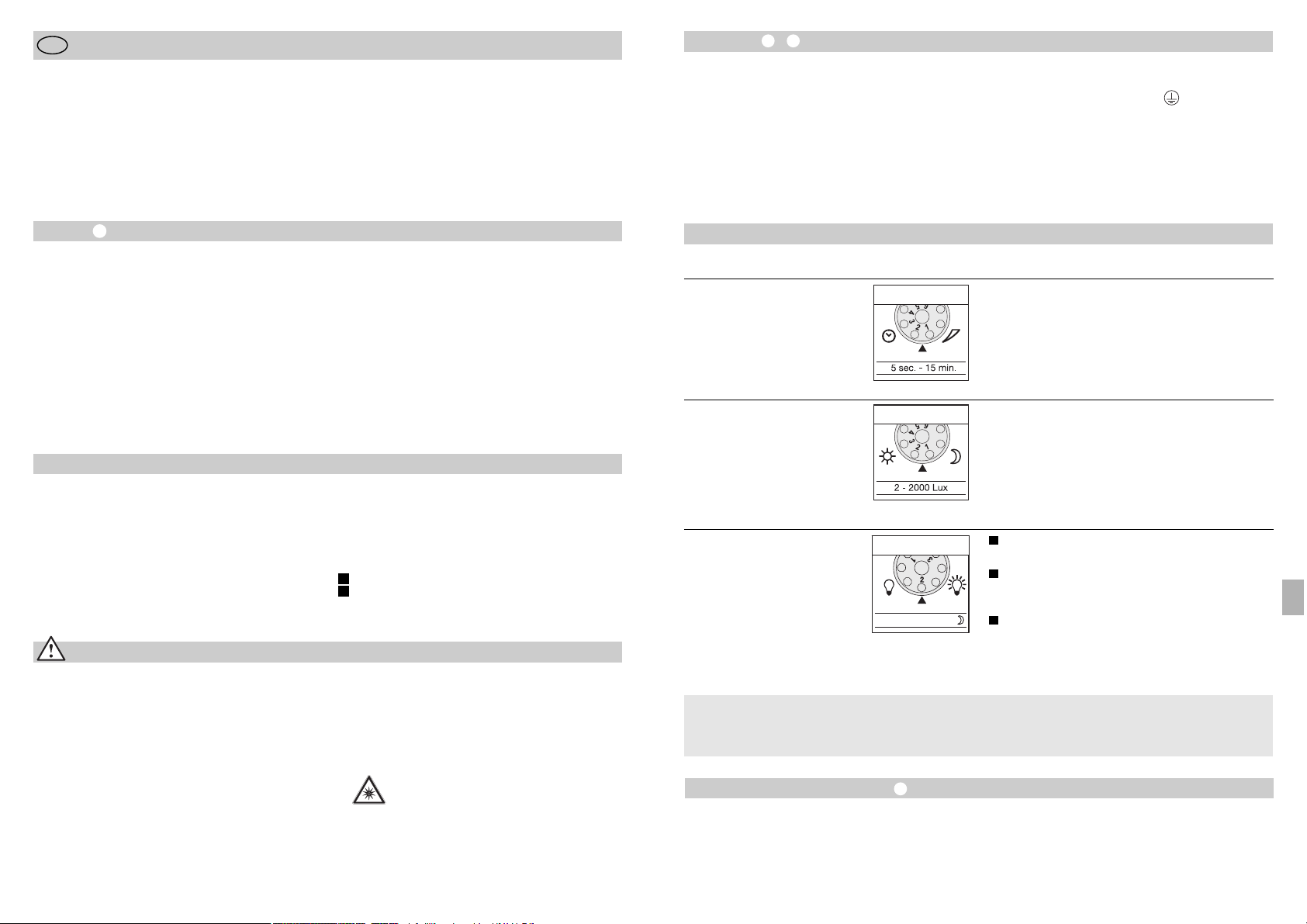
Inštalácia –
Miesto montáže by malo byť vzdialené minimálne
50 cm od iného svietidla, keďže tepelné žiarenie
môže viesť k spusteniu systému. Aby ste dosiahli
uvedený dosah max. 12 m, mala by montážna výška
predstavovať cca 2 m. Namontujte prístroj na pevný
podklad, aby ste zabránili chybnému zapínaniu.
Sieťový prívod pozostáva z jedného 3-žilového kábla:
- 67 -
Funkcie
Oneskorenie vypnutia
(nastavenie času)
(nastavenie od výrobcu: 5 s)
Plynulo nastaviteľná doba svietenia 5 s –15 min.
Nastavovací regulátor v polohe 1 (na ľavý doraz) =
najkratší čas (5 s)
Nastavovací regulátor v polohe 6 (na pravý doraz) =
najdlhší čas (15 min.)
Pri nastavovaní oblasti snímania sa odporúča nastavenie najkratšieho času 1.
Základný jas
(nastavenie od výrobcu:
program 1)
Žiarič ZAP pri pohybe od nastavenej hodnoty
zotmenia / žiaden základný jas.
Žiarič ZAP pri pohybe od nastavenej hodnoty
zotmenia / + základný jas (10 %) na 10 min.
po ubehnutí nastaveného času.
Žiarič sa zapne pri pohybe od nastavenej hodnoty
súmrakového spínača / + základný jas (10 %) po
celú noc.
Nastavenie súmraku:
(prah aktivovania)
(nastavenie od výrobcu:
prevádzka pri dennom
svetle 2000 lx)
Plynulo nastaviteľný prah citlivosti senzora od
2 – 2000 lx.
Nastavovací regulátor v polohe 1 (na ľavý doraz) =
prevádzka pri dennom svetle cca 2000 lx.
Nastavovací regulátor v polohe 6 (na pravý doraz) =
prevádzka pri zotmení cca 2 lx.
Pre nastavenie oblasti snímania pri dennom svetle sa
musí nastavovací regulátor nastaviť na 1 (prevádzka
pri dennom svetle).
LED 10% OFF / 10 min. / ~
1
2
3
Všetky funkcie sa dajú nastavovať s odstránenou
kruhovou clonou.
Čo je základný jas ?
Základný jas umožňuje osvetlenie s cca 10 % svetelného výkonu. Až pri pohybe v oblasti snímania sa
svetlo zapne (na nastavený čas, pozri oneskorenie
vypnutia ) na maximálny svetelný výkon (100 %).
Potom sa svietidlo prepne na dobu 10 min. na základný jas (cca 10 %).
Nastavenie dosahu/regulácia
Podľa potreby možno oblasť snímania optimalizovať.
Priložené kryty slúžia na zakrytie ľubovoľného počtu
šošovkových segmentov, resp. na individuálne skrátenie dosahu. Tým sa vylúči chybné zapnutie spôsobené
napr. okoloidúcimi automobilmi, chodcami atď., alebo
sa dosiahne cielené monitorovanie rizikových miest.
Kryty možno rezať alebo strihať nožnicami pozdĺž
drážkovaných dielikov vo zvislom a vodorovnom smere. Po odstránení kruhovej clony treba tieto zavesiť v
hornej časti senzorovej šošovky. Následne treba kruhovú clonu opäť nasadiť, čím sa kryty pevne uchytia.
Otáčaním telesa senzora o ± 80° je navyše možné
jemné doladenie.
L = fáza (zvyčajne čierna alebo hnedá)
N = nulový vodič (zväčša modrý)
PE = ochranný vodič (zelený/žltý)
Dôležité: Zámena prípojných káblov vedie v prístroji
alebo vo Vašej poistkovej skrini neskôr ku skratu.
V tomto prípade treba jednotlivé káble identifikovať
a nanovo zapojiť. Do sieťového prívodného vedenia
sa môže nainštalovať vhodný sieťový vypínač na
zapínanie a vypínanie.
- 66 -
Návod na montáž
Vážený zákazník,
ďakujeme Vám za dôveru, ktorú ste do nás vložili pri
zakúpení tohto nového senzorového LED-žiariča
STEINEL. Rozhodli ste sa pre vysokohodnotný kvalitný produkt, ktorý bol vyrobený, testovaný a balený
s najvyššou starostlivosťou.
SK
Bezpečnostné pokyny
■ Pred všetkými prácami na prístroji prerušiť prívod
elektrického napätia!
■ Pri montáži musí byť pripájané elektrické vedenie
bez napätia. Preto je potrebné najskôr vypnúť elektrický prúd a skontrolovať beznapäťovosť pomocou
skúšačky napätia.
■ Pri inštalácii týchto prístrojov ide o prácu na sieťovom napätí; musí sa preto vykonať odborným spôsobom podľa špecifických inštalačných predpisov
a podmienok pripojenia platných v danej krajine
použitia (D-VDE 0100, A-ÖVE/ÖNORM E 8001-1,
-SEV 1000)
Prosím oboznámte sa pred inštaláciou s týmto
montážnym návodom. Pretože len správna inštalácia
a uvedenie do prevádzky zaručujú dlhodobú
spoľahlivú a bezporuchovú prevádzku.
Želáme Vám veľa potešenia z Vášho nového senzorového LED-žiariča STEINEL.
■ Nemontujte prístroj na bežne ľahko horľavých
povrchoch.
■ Vhodné pre exteriérovú a interiérovú montáž.
■ Senzorový LED-žiarič je určený len na nástennú
montáž a nie na montáž na strope.
■ Kryt žiariča sa počas prevádzky zohrieva. Nasmerovanie hlavy LED hlavy vykonávajte len vtedy, ak už
je hlava vychladnutá.
■ Nepozerajte sa do svetla LED z krátkej
vzdialenosti alebo dlhší čas (> 5 min.).
Môže to viesť k poškodeniu sietnice.
Princíp
Pohyb zapína svetlo, alarm a mnoho viac. Pre Vaše
pohodlie, pre Vašu bezpečnosť. Či v súkromnej oblasti
na osvetlenie domu a pozemku alebo v podnikateľskej
sfére napr. na osvetlenie firemného pozemku, tento
senzorový LED-žiarič je všade rýchlo namontovaný
a pripravený k prevádzke.
Senzorové LED-žiariče XLed 10 a XLed 25 sú vybavené
dvomi 120° pyro-senzormi, ktoré snímajú neviditeľné
tepelné žiarenie pohybujúcich sa telies (ľudí, zvieratto
zosnímané tepelné žiarenie sa elektronicky prevedie a
zapne tak žiarič. Cez prekážky, ako napr. múry alebo
sklenené tabule, nie je tepelné žiarenie registrované.
Prostredníctvom dvoch pyrosenzorov sa dosahuje uhol
snímania 240° s uhlom otvorenia 180°.
Dôležité: Najistejšie snímanie pohybu dosiahnete,
ak prístroj namontujete bočne na smer pohybu a ak
výhľad senzora neobmedzujú žiadne prekážky (ako
napr. stromy, múry atď.).
Popis prístroja
LED hlava s plochým dizajnom "Flat-Design"
Kĺbové rameno
Chladiace rebrá
Nástenný držiak so sieťovým zdrojom
Senzorová jednotka
Tesniaca zátka
Krycie clony
Princíp
Nastavenie času
Nastavenie stmievania
Nastavenie základného jasu
Nastavenie dosahu / Vyladenie oblasti snímania
Funkcia trvalého svetla
Tesniaca zátka (upevňovacie otvory)
Sieťové pripojenie, prívod, podomietkové
Sieťové pripojenie, prívod, nadomietkové
I
II
SK
Page 35
- 69 -
Záruka funkčnosti
Tento výrobok Steinel je vyrobený s maximálnou dôslednosťou, skontrolovaný na funkčnosť a bezpečnosť
podľa platných predpisov a následne podrobený
náhodnej skúšobnej kontrole. STEINEL preberá záruku
bezchybného stavu a funkčnosti. Záručná doba je 36
mesiacov a začína plynúť dňom predaja spotrebiteľovi.
Odstránime nedostatky zakladajúce sa na chybe materiálu alebo výroby, záručné plnenie sa uskutočňuje
formou opravy alebo výmeny chybných dielcov podľa
nášho uváženia. Záručné plnenie sa nevzťahuje na poškodenie opotrebiteľných dielov ani na škody a nedostatky, ktoré vznikli neodbornou manipuláciou
alebo údržbou. Ďalšie následné škody na cudzích
veciach sú zo záruky vylúčené.
Záruku poskytneme len vtedy, ak nerozmontovaný prístroj spolu so stručným popisom chyby, pokladničným
blokom alebo faktúrou (dátum zakúpenia a pečiatka
predajcu) zašlete dobre zabalený na adresu príslušného
servisu.
Servis pre opravy:
Po uplynutí záručnej doby alebo v prípade chýb, na ktoré sa nevzťahuje
záruka, vykonáva opravy náš dielenský
servis. Pošlite, prosím, dobre zabalený
výrobok na adresu najbližšieho servisu.
Vyhlásenie o zhode
Tento výrobok spĺňa smernicu o nízkom napätí
2006/95/ES, smernicu EMC 2004/108/ES ako aj
smernicu RoHS 2002/95/ES.
Prevádzkové poruchy
Senzorový LED-žiarič bez napätia
Senzorový LED-žiarič sa nezapína
Senzorový LED-žiarič sa nevypína
Senzorový LED-žiarič sa neželane
zapína
Porucha
■ chybná poistka, svietidlo nie je
zapnuté, prerušené vedenie
■ skrat
■ nová poistka, zapnúť sieťový
spínač; skontrolovať vedenie
pomocou skúšačky napätia
■ skontrolovať pripojenie
■ pri dennej prevádzke, nasta-
venie stmievania je nastavené
na nočnú prevádzku
■ sieťový vypínač VYPNUTÝ
■ poistka defektná
■ oblasť snímania nie je cielene
nastavená
■ nastaviť nanovo
■ zapnúť
■ vymeniť poistku za novú príp.
skontrolovať pripojenie
■ vykonať reguláciu nanovo
■ trvalý pohyb v oblasti snímania ■ skontrolovať oblasť a príp.
znovu nastaviť resp. prikryť
■ vietor hýbe stromami a kríkmi
v oblasti snímania
■ dochádza k snímaniu automobilov na ceste
■ náhla zmena teploty spôsobená
počasím (vietor, dážď, sneh)
alebo vyfukovaným vzduchom
z ventilátorov, otvorených okien
■ senzorový LED-žiarič sa kolíše
(hýbe sa) kvôli napr. veterným
poryvom alebo silným zrážkam
■ prestaviť oblasť
■ prestaviť oblasť
■ zmeniť oblasť snímania,
preložiť miesto montáže
■ senzorový LED-žiarič namontovať na pevnom podklade
Príčina Riešenie
Senzorový LED-žiarič sa neustále
zapína/vypína
■ zvieratá sa pohybujú v oblasti
snímania
■ Senzor otočiť vyššie resp.
cielene prikryť; zmeniť oblasť,
resp. prikryť
- 68 -
Prevádzka a starostlivosť
Nie je vhodné pre špeciálne poplašné systémy proti
vlámaniu, keďže nie je predpísaným spôsobom
zabezpečené proti zneužitiu. Poveternostné podmienky môžu ovplyvniť funkciu senzorového LED-žiariča.
Pri silných nárazoch vetra, snehu, daždi, krupobití
môže dôjsť k chybnému zapnutiu, pretože náhle
tepelné výkyvy nie je možné rozlíšiť od tepelných
zdrojov.
Snímaciu šošovku môžete v prípade znečistenia
vyčistiť pomocou vlhkej handričky (bez čistiaceho
prostriedku).
Funkcia nepretržitého svietenia
Ak sa k sieťovému prívodu namontuje sieťový spínač, sú
okrem jednoduchého zapnutia a vypnutia možné nasledovné funkcie:
Senzorová prevádzka
1) Zapnutie svetla (keď je žiarič VYP):
Spínač 1 x VYPNÚŤ a ZAPNÚŤ.
LED ostanú počas nastavenej doby zapnuté.
2) Vypnutie svetla (keď je žiarič ZAP):
Spínač 1 x VYPNÚŤ a ZAPNÚŤ.
Žiarič sa vypne, resp. sa prepne na senzorovú prevádzku.
Režim nepretržitého svietenia
1) Zapnutie režimu nepretržitého svietenia:
Spínač 2 x VYPNÚŤ a ZAPNÚŤ. Žiarič sa prepne na
dobu 4 hodín na trvalé svietenie (rozsvieti sa červená
kontrolka LED za šošovkou). Následne sa automaticky
znovu prepne do senzorovej prevádzky (červená LED
vypnutá).
2) Vypnutie nepretržitého svietenia:
Spínač 1 x VYPNÚŤ a ZAPNÚŤ. Žiarič sa vypne,
resp. sa prepne na senzorovú prevádzku.
Dôležité:
Viacnásobné stlačenie spínača by malo byť vykonané
rýchlo za sebou (v rozsahu 0,5 – 1 s).
Technické údaje
Senzorový LED-žiarič XLed 10 XLed 25
Výkon: 10 LED, cca 25 W 25 LED, cca 60 W
Farba svetla: cca 4000 K (teplá biela) cca 4000 K (teplá biela)
Svetelný tok: 960 lúmenov 2120 lúmenov
Doplnkový spínací výkon:
Žiarovky, max. 800 W pri 230 V AC
Žiarivky, max. 400 W pri cos ϕ = 0,5,
induktívne zaťaženie pri 230 V AC
Žiarivky, energeticky úsporné žiarovky,
LED svietidlá s elektronickým predradeným prístrojom pri 230 V AC,
4 x max. je 60 W, C ≤ 88 µF
Životnosť LED: až 50 000 hod. až 50 000 hod.
(pri 3 h/deň cca 45 rokov) (až 3 h/deň cca 45 rokov)
Uhol snímania: 240° s ochranou proti podlezeniu 240° s ochranou proti podlezeniu
Osvetľovaná plocha 250 cm2+ 103,36 cm
2
420 cm2+ 103,36 cm
2
Otočný rozsah
senzorovej jednotky: ± 80° ± 80°
Otočný rozsah krytu: vertikálne 200° vertikálne 200°
horizontálne 270° horizontálne 270°
Nastavenie času: 5 s – 15 min. 5 s – 15 min.
Nastavenie stmievania 2 – 2000 lx 2 – 2000 lx
Regulácia jasu: 10 % základný jas (cca 3 W) 10 % základný jas (cca 6 W)
Nepretržité svietenie: 4 hod. nastaviteľné 4 hod. nastaviteľné
Rozmery V x Š x H) 205 x 200 x 220 mm 300 x 200 x 220 mm
Hmotnosť: 2200 g 2960 g
Teplotný rozsah: -20 °C až +50 °C -20 °C až +50 °C
Krytie: IP 44 IP 44
Trieda ochrany: I I
SK
Page 36

Instalacja –
Miejsce montażu powinno być oddalone o co najmniej
50 cm od następnej lampy oświetleniowej, ponieważ
promieniowanie cieplne może spowodować błędne działanie systemu. W celu uzyskania podanego zasięgu czujnika
wynoszącego 12 m wysokość montażu powinna wynosić
ok. 2 m. Urządzenie należy zamontować na stabilnym podłożu, aby wyeliminować czynniki zakłócające prawidłowe
działanie czujnika.
Przewód zasilający jest kablem 3-żyłowym:
- 71 -
Funkcje
Opóźnienie wyłączenia
(ustawianie czasu załączenia)
(ustawienie fabryczne: 5 s)
Płynnie ustawiany czas świecenia w zakresie 5 s – 15 min
Pokrętło regulacyjne ustawione na cyfrze 1
(do oporu w lewo) = najkrótszy czas (5 s)
Pokrętło regulacyjne ustawione na cyfrze 6
(do oporu w prawo) = najdłuższy czas (15 min)
Podczas ustawiania zasięgu czujnika zalecamy ustawienie
najkrótszego czasu świecenia 1.
Jasność podstawowa
(ustawienie fabryczne: program 1)
WŁĄCZENIE reflektora od zaprogramowanego progu
czułości zmierzchowej/bez funkcji jasności podstawowej.
WŁĄCZENIE reflektora na skutek ruchu od zaprogramowanego progu czułości zmierzchowej/+ świecenie
z jasnością podstawową (10%) przez 10 min po upływie
ustawionego czasu.
WŁĄCZENIE reflektora na skutek ruchu od zaprogramowanego progu czułości zmierzchowej/+ funkcja jasności
podstawowej (10%) przez całą noc.
Ustawianie progu czułości
zmierzchowej
(ustawienie fabryczne:
praca przy świetle dziennym,
2000 luksów)
Płynnie ustawiany próg czułości czujnika w zakresie
2 – 2000 luksów.
Pokrętło regulacyjne ustawione na cyfrze 1
(do oporu w lewo) = praca przy świetle dziennym
ok. 2000 luksów.
Pokrętło regulacyjne ustawione na cyfrze 6
(do oporu w prawo) = praca o zmierzchu ok. 2 luksów.
Podczas ustawiania zasięgu czujnika przy świetle dziennym
ustawić pokrętło regulacyjne na cyfrze 1 (dzienny tryb pracy).
LED 10% OFF / 10 min. / ~
1
2
3
Wszystkie funkcje można ustawiać po zdjęciu
przesłony pierścieniowej.
Co to jest jasność podstawowa ?
Funkcja jasności podstawowej umożliwia oświetlenie
z mocą ok. 10%. Dopiero na skutek ruchu w obszarze
wykrywania czujnika światło zostaje przełączone na maksy-
malną moc (100%) i świeci w ustawionym czasie (patrz
Opóźnienie wyłączania
). Potem lampa przełącza się
ponownie i świeci z jasnością podstawową (ok. 10% mocy).
Ustawianie zasięgu czujnika/regulacja
W zależności od potrzeb można zoptymalizować obszar
wykrywania. Przesłony należące do wyposażenia służą do
zasłonięcia dowolnej ilości segmentów soczewki lub do
indywidualnego skrócenia zasięgu czujnika. W ten sposób
eliminuje się czynniki mogące zakłócić prawidłowe działanie
czujnika, np.: samochody lub przechodniów itp., bądź też
można wybiórczo kontrolować wybrane strefy. Przesłony
można rozdzielić wzdłuż przygotowanych w tym celu piono-
wych lub poziomych rowków albo rozciąć nożyczkami.
Przesłony należy zaczepić w górnej części soczewki czujnika po zdjęciu przesłony pierścieniowej. Następnie założyć
z powrotem przesłonę pierścieniową, która unieruchomi
pozostałe przesłony.
Ponadto możliwe jest dokładne ustawienie czujnika przez
obracanie obudowy czujnika o ± 80°
.
L = przewód fazowy (najczęściej czarny lub brązowy)
N = przewód neutralny (najczęściej niebieski)
PE = przewód ochronny (zielono-żółty)
Ważne: Pomylenie przyłączy przewodów powoduje zwarcie
w urządzeniu lub w skrzynce bezpieczników. W takim przypadku należy jeszcze raz zidentyfikować poszczególne żyły
przewodu i ponownie je podłączyć. W przewodzie zasilającym można oczywiście zainstalować odpowiedni wyłącznik
sieciowy służący do ręcznego włączania/wyłączania.
- 70 -
Instrukcja montażu
Szanowny Nabywco!
Dziękujemy za zaufanie wyrażone zakupem nowego reflektora diodowego z czujnikiem ruchu marki STEINEL. Jest to
wysokiej jakości wyrób, który wyprodukowano, przetestowano i zapakowano z największą starannością.
PL
Zasady bezpieczeństwa
■
Przed przystąpieniem do jakiejkolwiek pracy przy urządzeniu należy wyłączyć napięcie zasilające!
■ Przewód zasilający, który należy podłączyć przy montażu
nie może być pod napięciem. Dlatego najpierw należy
wyłączyć prąd i sprawdzić brak napięcia za pomocą
próbnika napięcia.
■
Podczas instalacji tego urządzenia mamy do czynienia
z pracą wykonywaną pod napięciem sieciowym. Dlatego
należy ją wykonać fachowo, zgodnie z obowiązującymi
w danym kraju przepisami dotyczącymi instalacji
i podłączania do zasilania elektrycznego (np: D-VDE
0100, A-ÖVE/ÖNORM E 8001-1, -SEV 1000)
Przed uruchomieniem prosimy zapoznać się z poniższą
instrukcją montażu. Tylko prawidłowa instalacja i uruchomienie urządzenia zapewniają długoletnią, niezawodną
i bezusterkową eksploatację.
Życzymy Państwu wiele radości z użytkowania nowego
reflektora diodowego z czujnikiem ruchu.
■
Nie wolno montować urządzenia na łatwopalnych
powierzchniach.
■
Przeznaczony do montażu na zewnątrz i wewnątrz
pomieszczeń.
■
Reflektor ledowy z czujnikiem ruchu jest przeznaczony
tylko do montażu na ścianie, a nie na suficie.
■
Obudowa włączonego reflektora nagrzewa się. Regulację
ustawienia głowicy ledowej należy wykonywać tylko po
ostygnięciu.
■
Nie wolno patrzeć z małej odległości lub przez
dłuższy czas (> 5 min) na lampę ledową. Może
to spowodować uszkodzenie siatkówki oka.
Zasada działania
Dla Twojego komfortu i bezpieczeństwa, na skutek ruchu,
włącza się światło, alarm i inne urządzenia. Czy to na
użytek prywatny do oświetlenia domu lub posesji, czy też
na użytek firmowy, np. do oświetlenia terenu zakładu wszędzie można szybko zamontować reflektory diodowe
z czujnikiem ruchu, które są natychmiast gotowe do użytku.
Reflektory diodowe z czujnikiem ruchu XLed 10 i XLed 25
są wyposażone w dwa czujniki piroelektryczne 120°, które
odbierają niewidzialne promieniowanie cieplne emitowane
przez poruszające się ciała (ludzi, zwierząt itp.). Zarejestro-
wane promieniowanie cieplne jest przetwarzane przez układ
elektroniczny, powodując automatyczne włączenie reflektora.
Przeszkody, np. mury lub szyby szklane, uniemożliwiają
wykrycie promieniowania cieplnego. Za pomocą dwóch
czujników piroelektrycznych uzyskuje się kąt wykrywania
240° z kątem rozwarcia 180°.
Ważne: Najpewniejsze wykrywanie poruszających się
obiektów uzyskuje się przy montażu urządzenia bokiem do
kierunku ruchu i przy braku przeszkód zasłaniających
czujnik (np. drzewa, mury).
Opis urządzenia
Głowica świetlna LED w płaskiej oprawie typu Flat-Design
Ramię przegubowe
Żebra chłodzące
Wspornik naścienny z zasilaczem
Moduł czujnika
Zaślepka uszczelniająca
Przesłony
Zasada działania
Ustawianie czasu załączenia
Ustawianie progu czułości zmierzchowej
Ustawianie jasności podstawowej
Ustawianie zasięgu czujnika/regulacja obszaru
wykrywania
Funkcja stałego świecenia
Zasilanie sieciowe - przewód podtynkowy
Zasilanie sieciowe - przewód natynkowy
I
II
PL
Page 37
- 73 -
Gwarancja funkcjonowania
Poniższy produkt firmy STEINEL został wykonany z dużą
starannością. Prawidłowe działanie i bezpieczeństwo użytkowania potwierdzają przeprowadzone losowo kontrole
jakości oraz zgodność z obowiązującymi przepisami. Firma
STEINEL udziela gwarancji na prawidłową jakość i działanie.
Okres gwarancji wynosi 36 miesięcy i rozpoczyna się
z dniem sprzedaży użytkownikowi. W ramach gwarancji
usuwamy braki wynikłe wynikające z wad materiałowych lub
produkcyjnych, świadczenie gwarancyjne nastąpi według
naszej decyzji przez naprawę lub wymianę wadliwych części. Gwarancja nie obejmuje uszkodzenia części podlegających zużyciu eksploatacyjnemu, uszkodzeń i usterek spowodowanych przez nieprawidłową obsługę lub konserwację.
Gwarancja nie obejmuje odpowiedzialności za szkody wtórne powstałe na przedmiotach trzecich.
Gwaracja jest udzielana tylko wówczas, gdy prawidłowo
zapakowane urządzenie (nierozłożone na części) wraz
z krótkim opisem usterki, paragonem lub rachunkiem zakupu (opatrzonym datą zakupu i pieczątką sklepu) zostanie do
odesłane właściwego punktu serwisowego.
Serwis naprawczy:
Po upływie okresu gwarancji albo w razie
usterek nieobjętych gwarancją naprawy
wykonuje nasz serwis firmowy. Prosimy
o przesłanie dobrze zapakowanego urządzenia do najbliższej placówki serwisowej.
Deklaracja zgodności z normami
Produkt spełnia wymogi dyrektywy niskonapięciowej
2006/95/WE, dyrektywy o kompatybilności elektromagnetycznej 2004/108/WE oraz dyrektywy 2002/95/WE
w sprawie stosowania niektórych niebezpiecznych
substancji w sprzęcie elektrycznym i elektronicznym.
Usterki
Brak napięcia zasilającego reflektor
ledowy z czunikiem ruchu
Reflektor ledowy z czujnikiem
ruchu nie zapala się
Reflektor ledowy z czujnikiem ruchu nie
wyłącza się
Reflektor ledowy z czujnikiem ruchu
zapala się w niepożądanym momencie
Usterka
■
przepalony bezpiecznik, nie włączony wyłącznik sieciowy, przerwany
przewód
■
zwarcie
■
wymienić bezpiecznik, włączyć
wyłącznik sieciowy; sprawdzić
przewód próbnikiem napięcia
■
sprawdzić podłączenia elektryczne
■
przy dziennym trybie pracy ustawiono próg czułości dla trybu nocnego
■
wyłączony wyłącznik sieciowy
■
uszkodzony bezpiecznik
■
niedokładnie ustawiony obszar
wykrywania czujnika
■
ustawić ponownie
■
włączyć
■
założyć nowy bezpiecznik,
ewentualnie sprawdzić
podłączenia elektryczne
■
wyregulować ponownie
■
w obszarze wykrywania czujnika
ciągle coś się porusza
■
skontrolować obszar wykrywania
czujnika, ewent. ponownie wyregulować lub zasłonić przesłonami
■
wiatr porusza gałęziami i krzewami
w obszarze wykrywania
■
czujnik rejestruje ruch pojazdów
na ulicy
■
gwałtowne zmiany temperatury na
skutek czynników atmosferycznych
(wiatr, deszcz, śnieg) lub nadmuch
z wentylatorów, otwartych okien
■
reflektor ledowy z czujnikiem ruchu
kołysze się (porusza się) pod wpływem porywów wiatru lub gwałtownych opadów
■
zmienić obszar wykrywania
■
zmienić obszar wykrywania
■
zmienić obszar wykrywania,
zmienić miejsce montażu
■
zamontować reflektor diodowy
z czujnikiem ruchu na twardym
podłożu
Przyczyna Usuwanie
Reflektor ledowy z czujnikiem ruchu
stale włącza się i wyłącza
■
w obszarze wykrywania czujnika
poruszają się zwierzęta
■
odchylić czujnik do góry lub dokładnie zakryć przesłonami; zmienić
obszar wykrywania czujnika lub
zasłonić przesłonami
- 72 -
Eksploatacja i konserwacja
Urządzenie nie nadaje się do specjalnych instalacji antywłamaniowych, gdyż nie posiada zabezpieczenia antysabotażowego, przewidzianego przepisami. Czynniki atmosferyczne
mogą mieć wpływ na funkcjonowanie reflektora ledowego
z czujnikiem ruchu. Silne wiatry, śnieg, deszcz lub grad
mogą spowodować błędne zadziałanie czujnika, ponieważ
nagłe zmiany temperatury nie dają się odróżnić od źródeł
ciepła.
Zabrudzoną soczewkę czujnika można oczyścić wilgotną
ściereczką (bez użycia środków czyszczących).
Funkcja stałego świecenia
Jeśli w przewodzie zasilającym zainstalowany jest wyłącznik
sieciowy, to oprócz zwykłego włączania i wyłączania
oświetlenia można ustawić następujące funkcje:
Tryb pracy czujnika
1) Włączanie światła (gdy reflektor jest wyłączony):
1 x wyłączyć i włączyć wyłącznik.
Diody będą świecić w zaprogramowanym czasie.
2) Wyłączanie światła (gdy reflektor jest włączony):
1 x wyłączyć i włączyć wyłącznik.
Reflektor gaśnie lub przełącza się w tryb pracy czujnika.
Funkcja stałego świecenia
1) Włączanie stałego świecenia:
2 x wyłączyć i włączyć wyłącznik. Reflektor jest ustawiony
przez 4 godziny w trybie stałego świecenia (świeci czerwona dioda za soczewką). Następnie automatycznie przełącza
się tryb pracy czujnika (czerwona dioda gaśnie).
2) Wyłączanie stałego świecenia:
1 x wyłączyć i włączyć wyłącznik. Reflektor gaśnie lub
przełącza się tryb pracy czujnika.
Ważne:
Kilkakrotne naciskanie wyłącznika należy wykonać raz za
razem w krótkich odstępach (w czasie 0,5 – 1 s).
Dane techniczne
Reflektor ledowy XLed 10 XLed 25
Moc: 10 diod LED, ok. 25 W 25 diod LED, ok. 60 W
Barwa światła: ok. 4000 kelwinów (ciepłe białe światło) ok. 4000 kelwinów (ciepłe białe światło)
Źródło światła: 960 lumenów 2120 lumenów
Dodatkowa moc przełączania:
Żarówki, maks. 800 W przy 230 V AC
Jarzeniówki, maks. 400 W przy cos ϕ = 0,5;
obciążenie indukcyjne przy 230 V AC
Świetlówki, żarówki energooszczędne, lampy LED z elektronicznym
urządzeniem stabilizacyjno-zapłonowym przy 230 V AC,
4x maks. 60 W, C ≤ 88 µF
Żywotność diod LED: do 50 000 godz do 50 000 godz
(przy 3 godz/dziennie ok. 45 lat) (przy 3 godz/dziennie ok. 45 lat)
Kąt wykrywania: 240° z zabezpieczeniem przed podpełzaniem 240° z zabezpieczeniem przed podpełzaniem
Oświetlana powierzchnia 250 cm2+ 103,36 cm
2
420 cm2+ 103,36 cm
2
Zakres obrotu
modułu czujnika: ± 80° ± 80°
Zakres obrotu obudowy: pionowo 200° pionowo 200°
poziomo 270° poziomo 270°
Ustawianie czasu załączenia: 5 s – 15 min 5 s – 15 min
Ustawianie czułości zmierzchowej: 2 – 2000 luksów 2 – 2000 luksów
Regulacja jasności: 10% jasności podstawowej (ok. 3 W) 10% jasności podstawowej (ok. 6 W)
Stałe oświetlenie: 4 godz (przełączalne) 4 godz (przełączalne)
Wymiary (wys. x szer. x gł.) 205 x 200 x 220 mm 300 x 200 x 220 mm
Ciężar: 2200 g 2960 g
Zakres temperatury: -20°C do +50°C -20°C do +50°C
Stopień ochrony: IP 44 IP 44
Klasa ochronności: I I
PL
Page 38

Instalarea –
Locul de montaj trebuie så se afle la o distanøå de cel
puøin 50 cm faøå de o altå lampå, deoarece radiaøia termicå
a acesteia poate produce declanμarea sistemului. Pentru a
obøine raza de acøiune indicatå de max. 12 m, înåløimea de
montaj trebuie så fie de cca. 2 m. Montaøi aparatul pe o
suprafaøå stabilå, solidå, pentru a evita acøionåri eronate.
Circuitul de alimentare este format dintr-un cablu cu 3 fire:
- 75 -
Funcøii
Temporizarea la decuplare
(Reglarea timpului)
(Reglaj din fabricå: 5 sec.)
Durata de aprindere este reglabilă continuu în limitele
5 sec. – 15 min.
Buton de reglaj poziøionat pe 1 (maxim la stânga) =
durata cea mai scurtå (5 sec.)
Buton de reglaj poziøionat pe 6 (maxim la dreapta) =
durata cea mai lungå (15 min.)
La reglarea domeniului de detecøie se recomandå selectarea
duratei cele mai scurte 1.
Lumina de veghe
(Reglaj din fabricå: programul 1)
Reflectorul se aprinde la detectarea miμcårii, începând
de la valoarea reglatå pentru crepuscularitate /
fårå luminå de veghe.
Reflectorul se aprinde la detectarea miμcårii, începând
de la valoarea setatå pentru crepuscularitate / + luminå
de veghe (10%) timp de 10 min. dupå expirarea duratei
reglate.
Lampa SE APRINDE la apariøia miμcårii pe parcursul
întregii nopøi, începând de la valoarea setatå pentru
crepuscularitate / + luminå de veghe (10%).
Reglarea crepuscularităţii
(Prag de declanμare)
(Reglaj din fabricå:
funcøionare la lumina zilei 2000 Lux)
Nivelul de activare a senzorului poate fi reglat continuu,
între 2 – 2000 lux.
Buton de reglaj poziøionat pe 1 (maxim la stânga) =
Funcøionare pe timp de zi cca. 2000 Lux.
Buton de reglaj poziøionat pe 6 (maxim la dreapta) =
Funcøionarea în regim de crepuscularitate cca. 2 Lux.
Pentru reglarea domeniului de detecøie la lumina zilei,
poziøionaøi butonul de reglaj pe 1 (funcøionare pe timp de zi).
LED 10% OFF / 10 min. / ~
1
2
3
Toate funcøiile pot fi reglate dupå demontarea
inelului decorativ.
Ce este lumina de veghe?
Lumina de veghe permite o iluminare cu cca. 10 % din
puterea luminoaså normalå. Lampa se aprinde cu putere
luminoaså maximå (100%) numai la detectarea miμcårii în
domeniul de detecøie (pentru durata reglatå; a se vedea
temporizarea la decuplare
). Dupå aceasta, lampa trece
pentru un timp de 10 min. pe luminå de veghe (cca. 10 %).
Stabilirea razei de acøiune / Reglaj
Domeniul de detecøie poate fi optimizat în funcøie de necesitåøi. Diafragmele de mascare livrate cu produsul servesc la
obturarea numårului dorit de segmente de lentilå, respectiv
la scurtarea individualå a razei de acøiune. Astfel sunt excluse declanμårile accidentale, de exemplu din cauza autoturismelor, a trecåtorilor etc. sau este posibilå supravegherea
concentratå a zonelor de pericol. Diafragmele de mascare
pot fi tåiate cu o foarfecå, pe orizontalå sau pe verticalå,
de-a lungul creståturilor existente. Dupå demontarea inelului
decorativ, acestea pot fi suspendate în partea superioarå a
lentilei senzorului. Dupå aceasta, inelul decorativ va fi introdus din nou, diafragmele de obturare fiind fixate rigid acum.
În plus, este posibil un reglaj fin prin rotirea carcasei senzorului cu ± 80°
.
L = fazå (de cele mai multe ori negru sau maro)
N = conductor de påmântare (de obicei albastru)
PE = conductor de påmântare (verde/galben)
Important: O inversare a racordurilor produce ulterior un
scurtcircuit în aparat sau în tabloul de siguranøe. În acest
caz fiecare cablu trebuie identificat μi conectat din nou. Pe
circuitul de alimentare electricå de la reøea poate fi montat
un întrerupåtor adecvat pentru cuplare μi decuplare.
- 74 -
Instrucøiuni de montare
Stimate client,
Vå muløumim pentru încrederea pe care ne-o aråtaøi prin
achiziøionarea noului dvs. reflector STEINEL cu LED-uri μi
cu senzor. V-aøi decis pentru un produs de înaltå calitate,
fabricat, testat μi ambalat cu cea mai mare grijå.
RO
Indicaøii de siguranøå
■
Înaintea oricåror lucråri la aparat, întrerupeøi alimentarea
electricå!
■
La montare, cablul electric care urmeazå så fie racordat
nu trebuie så fie sub tensiune. Din acest motiv, în primul
rând se decupleazå curentul μi se verificå absenøa tensiunii cu ajutorul unui testor de tensiune.
■
La instalarea acestor aparate, este vorba de lucråri la
tensiunea reøelei electrice; din acest motiv, aceste lucråri
trebuie efectuate cu respectarea condiøiilor de racord μi
a prevederilor privind instalarea, specifice øårii respective
(D-VDE 0100, A-ÖVE/ÖNORM E 8001-1,
-SEV 1000)
Înainte de efectuarea lucrårilor de instalare, vå rugåm så
parcurgeøi prezentele instrucøiuni de montaj. Aceasta
deoarece numai o instalare μi o punere în funcøiune
corespunzåtoare asigurå o funcøionare de lungå duratå,
fiabilå μi fårå defecøiuni.
Vå dorim så folosiøi cu multå plåcere noul dvs. reflector
STEINEL cu LED-uri μi senzor.
■
Nu montaøi aparatul pe suprafeøe uμor inflamabile.
■
Adecvat pentru spaøii exterioare μi interioare.
■
Reflectorul cu LED-uri μi senzor este prevåzut numai
pentru montajul pe perete, nu μi pentru montajul pe
tavan.
■
Carcasa reflectorului se încålzeμte în timpul funcøionårii.
Efectuaøi alinierea acesteia numai dupå ce s-a råcit.
■
Nu priviøi de la micå distanøå sau timp mai
îndelungat (peste 5 min.) în lampa cu LED-uri.
În caz contrar poate fi afectatå retina.
Principiul de funcøionare
Miμcarea comutå lumina, alarma μi multe altele, pentru
confortul μi siguranøa dumneavoastrå. Indiferent dacå este
vorba de un domeniu privat, de exemplu pentru iluminarea
casei sau a terenului aferent, sau de un domeniu comercial,
de exemplu pentru iluminarea terenului unei firme, acest
reflector cu LED-uri μi senzor poate fi montat μi pregåtit
rapid pentru funcøionare.
Reflectoarele cu LED-uri μi senzor XLed 10 μi XLed 25 sunt
echipate cu doi pirosenzori de 120° care detecteazå radiaøia
caloricå invizibilå a corpurilor în miμcare (oameni, animale,
etc.). Radiaøia caloricå astfel detectatå este transformatå pe
cale electronicå μi comandå aprinderea reflectorului. Prin
obstacole, cum ar fi ziduri sau geamuri, nu se poate detecta
radiaøia termicå. Cu ajutorul celor doi pirosenzori se obøine
un unghi de cuprindere de 240° cu un unghi de acoperire
de 180°.
Important: Cea mai sigurå detectare a miμcårii o obøineøi
când amplasaøi aparatul lateral faøå de direcøia de mers μi
când nu existå niciun fel de obstacole (cum ar fi pomi,
ziduri, etc.) care så obtureze raza de acøiune a senzorilor.
Descrierea dispozitivului
Carcaså cu LED-uri, în design plat
Braø pivotant
Aripioare de råcire
Suport de perete cu bloc de alimentare
Unitate cu senzor
Buμon de etanμare
Lentile de acoperire
Principiul de funcøionare
Reglarea timpului
Reglarea crepuscularităţii
Reglarea luminii de veghe
Reglarea razei de acøiune /
Reglarea domeniului de detecøie
Funcøionarea cu aprindere permanentå
Racordul la reøea cu cablu sub tencuialå
Racordul la reøea cu cablu pe tencuialå
l
II
RO
Page 39

- 77 -
Garanøia de funcøionare
Acest produs STEINEL a fost fabricat μi controlat din punct
de vedere funcøional μi al siguranøei conform prevederilor în
vigoare, dupå care a fost supus unei probe de funcøionare
prin sondaj. STEINEL asigurå garanøia pentru o construcøie
μi o funcøionare ireproμabilå.
Termenul de garanøie este de 36 de luni μi începe de la data
vânzårii produsului cåtre consumator. Garanøia acoperå deficienøele bazate pe defecte de material μi fabricaøie. Îndeplinirea garanøiei se realizeazå prin repararea sau înlocuirea
pieselor defecte conform opøiunii noastre. Garanøia nu se
aplicå pieselor de uzurå μi nici deteriorårilor sau deficienøelor
cauzate de utilizarea sau întreøinerea necorespunzåtoare.
Pentru daunele provocate altor obiecte nu se asigurå garanøie.
Garanøia se asigurå numai atunci când aparatul va fi trimis
bine ambalat, fårå a fi demontat, la punctul de service
corespunzåtor, însoøit de o descriere a defecøiunii, de bonul
de caså sau de factura de cumpårare (cu data cumpårårii
μi μtampila magazinului).
Reparaøii:
Dupå expirarea termenului de garanøie
sau în caz de defecøiuni fårå pretenøie de
garanøie, reparaøiile se efectueazå de
cåtre atelierul nostru service. Vå rugåm
så trimiteøi produsul bine ambalat la cel
mai apropiat atelier de service.
Declaraøie de conformitate
Acest produs corespunde Directivei pentru joaså tensiune
2006/95/CE, Directivei pentru compatibilitate electromagneticå 2004/108/CE precum μi Directivei RoHS 2002/95/CE.
Defecøiuni în funcøionare
Lipså tensiune reflector cu LED-uri
μi senzor
Reflectorul cu LED-uri μi senzor
nu se aprinde
Reflectorul cu LED-uri μi senzor
nu se stinge
Reflectorul cu LED-uri μi senzor
se aprinde în mod nejustificat
Deranjamentul
■
Siguranøå defectå, aparat
neconectat, cablu întrerupt
■
Scurtcircuit
■
Siguranøå nouå; cuplaøi întrerupåtorul de reøea; se verificå prezenøa
tensiunii cu un testor de tensiune
■
Verificaøi legåturile
■
În regim de zi, reglajul de
crepuscularitate este plasat
pe regim de noapte
■
Întrerupåtor decuplat
■
Siguranøå defectå
■
Domeniul de detecøie nu este reglat
corespunzåtor
■
Se regleazå din nou
■
Se cupleazå
■
Se înlocuieμte siguranøa,
eventual se verificå legåturile
■
Se regleazå din nou
■
Miμcare permanentå în
intervalul de sesizare
■
Controlaøi zona μi refaceøi reglajele,
eventual introduceøi diafragme de
mascare
■
Vântul miμcå pomii μi tufiμurile în
domeniul de detecøie
■
Este detectat traficul auto de pe
μosea
■
Modificarea bruscå a temperaturii
datoritå intemperiilor (vânt, ploaie,
zåpadå) sau sesizarea aerului
evacuat de ventilatoare, ferestre
deschise
■
Reflectorul cu LED-uri μi senzor
oscileazå (se miμcå) datoritå
rafalelor de vânt sau datoritå
precipitaøiilor puternice
■
Reconfiguraøi domeniul
■
Reconfiguraøi domeniul
■
Modificaøi domeniul, schimbaøi
locul de montaj
■
Montaøi reflectorul cu LED-uri
μi senzor pe o suprafaøå stabilå,
solidå
Cauza Remediul
Reflectorul cu LED-uri μi senzor comutå
frecvent între stårile aprins μi stins
■
În domeniul de detecøie se miμcå
animale
■
Basculaøi senzorul mai sus,
respectiv obturaøi-l parøial;
Modificaøi domeniul,
respectiv obturaøi
- 76 -
Utilizare μi îngrijire
Aparatul nu este recomandat pentru instalaøiile de alarmå
speciale deoarece nu este echipat cu sistemul prevåzut în
acest sens de siguranøå împotriva sabotajului. Influenøele
intemperiilor pot afecta funcøionarea reflectorului cu LED-uri
μi senzor. În cazul unor fenomene meteorologice puternice,
cum ar fi rafale de vânt, zåpadå, ploaie, grindinå, pot apårea
acøionåri accidentale, deoarece variaøiile bruμte de temperaturå nu pot fi deosebite de sursele de cåldurå.
În caz de murdårire, lentila de înregistrare poate fi curåøatå
cu ajutorul unei lavete umede (fårå detergent).
Funcøionare permanentå
Dacå se monteazå în circuit μi un întrerupåtor de la reøea,
pe lângå funcøiile simple de conectare μi deconectare mai
sunt disponibile μi urmåtoarele funcøii:
Funcøionarea senzorului
1) Aprinderea luminii (când reflectorul este oprit):
Întrerupåtorul 1 x OPRIT μi PORNIT.
LED-urile råmân aprinse pe durata reglatå.
2) Stingerea luminii (când reflectorul este pornit):
Întrerupåtorul 1 x OPRIT μi PORNIT.
Reflectorul se stinge, respectiv trece în regim de luminå
de veghe.
Iluminat continuu
1) Activarea iluminatului continuu:
Întrerupåtorul 2 x OPRIT μi PORNIT. Reflectorul råmâne în
regim de aprindere permanentå timp de 4 ore (LED-ul roμu
este aprins în spatele lentilei). Ulterior revine automat în
regimul de operare senzorial (LED-ul roμu stins).
2) Dezactivarea iluminatului continuu:
Întrerupåtorul 1 x OPRIT μi PORNIT. Reflectorul se stinge,
respectiv trece în regim de luminå de veghe.
Important:
Acøionarea repetatå a comutatorului trebuie fåcutå la
intervale scurte (în intervalul 0,5 – 1 sec.).
Date tehnice
Reflector cu LED-uri μi senzor XLed 10 XLed 25
Putere: 10 LED-uri, cca. 25 W 25 LED-uri, cca. 60 W
Temperaturå termodinamicå: aprox. 4000 de kelvini (alb cald) aprox. 4000 de kelvini (alb cald)
Fluxul luminos: 960 lumeni 2120 lumeni
Putere comutatoare suplimentarå:
Becuri cu incandescenøå, max. 800 W la 230 V c.a.
Tub fluorescent, max. 400 W la cos ϕ = 0,5,
sarcinå inductivå la 230 V c.a.
Becuri fluorescente, becuri economice,
låmpi cu diode μi cu rezistenøå electronicå de balast la 230 V c.a.,
4 x max. 60 W, C ≤ 88 µF
Duratå de viaøå a LED-urilor: pânå la 50.000 ore pânå la 50.000 ore
(cca. 45 de ani la 3 ore/zi) (cca. 45 de ani la 3 ore/zi)
Unghi de detecøie: 240° cu protecøie împotriva trecerii 240° cu protecøie împotriva trecerii
pe sub senzor pe sub senzor
Suprafaøå de proiecøie 250 cm2+ 103,36 cm
2
420 cm2+ 103,36 cm
2
Domeniu de rabatare
a unitåøii cu senzor: ± 80° ± 80°
Domeniu de rabatare carcaså: vertical 200° vertical 200°
orizontal 270° orizontal 270°
Reglaj de temporizare: 5 sec. – 15 min. 5 sec. – 15 min.
Reglaj de crepuscularitate: 2 – 2000 Lux 2 – 2000 Lux
Control luminozitate: 10% luminå de veghe (cca. 3 W) 10% luminå de veghe (cca. 6 W)
Iluminat permanent: 4 ore, reglabil 4 ore, reglabil
Dimensiuni (H x L x P) 205 x 200 x 220 mm 300 x 200 x 220 mm
Greutate: 2200 g 2960 g
Interval termic: între -20°C μi +50°C între -20°C μi +50°C
Tip de protecøie: IP 44 IP 44
Claså de protecøie: I I
RO
Page 40
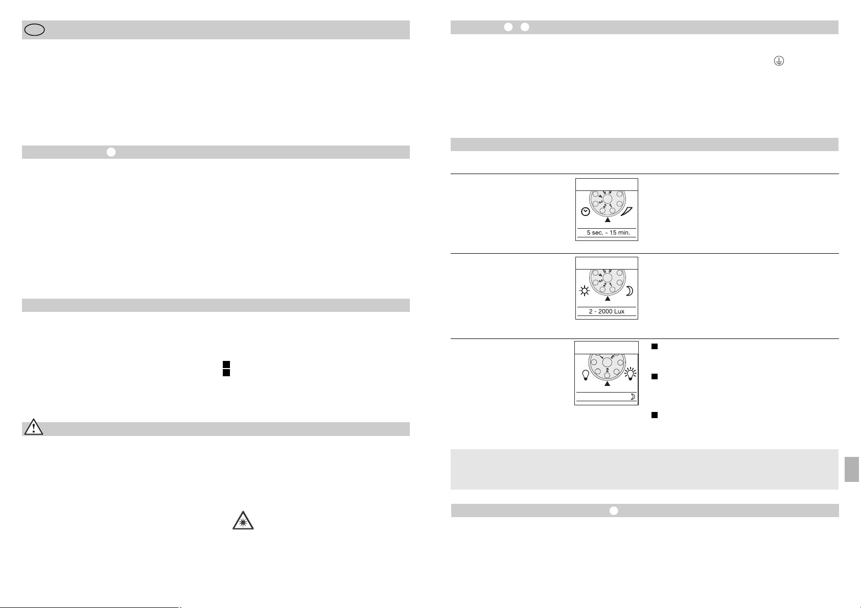
Inštalacija –
Mesto montaže mora biti vsaj 50 cm oddaljeno od
drugih virov svetlobe (svetilk, luči), saj lahko njihovo
toplotno sevanje povzroči neželene vklope. Da boste
zagotovili navedeni doseg 12 m, mora biti montažna
višina pribl. 2 m. Napravo montirajte na trdno podlago, da boste preprečili neželene vklope.
Omrežno napeljavo sestavlja 3-žilni kabel:
- 79 -
Funkcije
Zakasnitev izklopa
(nastavitev časa)
(tovarniška nastavitev: 5 sek.)
Brezstopenjsko nastavljivo trajanje svetenja od
5 sek. – 15 min.
Nastavitveni gumb v položaju 1 (skrajno levo) =
najkrajši čas (5 sek.)
Nastavitveni gumb v položaju 6 (skrajno desno) =
najdaljši čas (15 min.)
Med nastavljanjem območja zaznavanja je
priporočljivo, da nastavite najkrajši čas svetenja 1.
Osnovna osvetlitev
(tovarniška nastavitev: program 1)
Reflektor se pri zaznanem premikanju VKLOPI,
kadar je dosežena nastavljena mejna osvetljenost
okolice / brez osnovne osvetlitve.
Reflektor se pri zaznanem premikanju VKLOPI,
kadar je dosežena nastavljena mejna osvetljenost
okolice / + osnovna osvetlitev (10 %) 10 min. po
poteku nastavljenega časa.
Reflektor je VKL. v primeru zaznanega premikanja
od nastavljene mejne osvetlitve okolice (vklopnega
praga) / + osnovna osvetlitev (10%) celo noč.
Nastavitev mejne osvetljenosti
okolice (vklopni prag)
(tovarniška nastavitev:
delovanje pri dnevni
svetlobi 2000 luksov)
Brezstopenjsko nastavljiv vklopni prag senzorja od
2 – 2000 luksov.
Nastavitveni gumb v položaju 1 (skrajno levo) =
delovanje pri dnevni svetlobi pri pribl. 2000 luksih
Nastavitveni gumb v položaju 6 (skrajno desno) =
obratovanje v mraku pri pribl. 2 luksih
Za nastavitev območja zaznavanja pri dnevni svetlobi
nastavitveni gumb nastavite na 1 (delovanje pri
dnevni svetlobi).
LED 10% OFF / 10 min. / ~
1
2
3
Vse funkcije lahko nastavite pri
snetem zaslonskem obroču.
Kaj je osnovna osvetlitev ?
Osnovna osvetlitev omogoča razsvetljavo s pribl.
10 % zmogljivosti svetenja. Šele po zaznanem premikanju v območju zaznavanja luč (za nastavljen čas,
gl. zakasnitev izklopa ) zasveti s polno zmogljivostjo
(100 %). Nato reflektor 10 min. sveti z osnovno
osvetlitvijo (pribl. 10 %).
Nastavitev dosega/fina nastavitev
Po potrebi lahko območje zaznavanja optimalno
omejite. S priloženimi zastirali lahko pokrijete poljubno število segmentov leče, s čimer lahko npr. individualno skrajšate doseg. Na ta način boste preprečili
neželene vklope zaradi avtomobilov ali mimoidočih,
ali pa ciljano nadzorovali tvegana območja. Zastirala
lahko ločite vzdolž naprej naluknjanih linij v vodoravni
ali navpični smeri ali razrežete s škarjami. Ko ste sneli
zaslonski obroč, zastirala namestite poleg senzorske
leče. Nato ponovno pritrdite zaslonski obroč, s čimer
boste fiksirali nameščena zastirala.
Poleg tega je z vrtenjem ohišja senzorja ± 80°
možna še fina nastavitev območja zaznavanja.
L = faza (največkrat rjava ali črna)
N = nevtralni vodnik (največkrat moder)
PE = zaščitni vodnik (zelen/rumen)
Pomembno: Če boste pomešali priključke, lahko
kasneje v napravi ali v varovalni omarici pride do
kratkega stika. V takem primeru morate identificirati
posamezne kable in jih na novo priključiti. V omrežni
kabel lahko montirate primerno omrežno stikalo za
VKLOP in IZKLOP.
- 78 -
Navodila za montažo
Cenjeni kupec,
zahvaljujemo se vam za zaupanje, ki ste nam ga
izkazali ob nakupu vašega novega senzorskega LED
reflektorja STEINEL. Odločili ste se za izjemno
kakovosten izdelek, ki je bil izdelan, testiran in pakiran
z veliko skrbnostjo.
SLO
Varnostni napotki
■ Pred vsakršnimi deli na napravi najprej odklopite vir
napetosti!
■ Med montažo električna napeljava, na katero boste
priključili napravo, ne sme biti pod napetostjo. Zato
najprej izklopite tok ter z indikatorjem napetosti
preverite, da napeljava ni pod napetostjo.
■ Pri inštalaciji tovrstnih naprav gre za delo na
omrežni napetosti; inštalacijo mora zato izvesti
strokovnjak v skladu z za vsako državo določenimi
inštalacijskimi predpisi in pogoji priključitve
(D-VDE 0100, A-ÖVE/ÖNORM E 8001-1,
-SEV 1000)
Pred inštalacijo si, prosimo, preberite ta navodila za
montažo. Le primerna inštalacija in uporaba namreč
zagotavljata dolgotrajno, zanesljivo in nemoteno
delovanje.
Želimo vam veliko veselja pri uporabi vašega novega
senzorskega LED reflektorja STEINEL.
■ Naprave ne montirajte na lahko vnetljive površine.
■ Naprava je primerna za zunanje in notranje
prostore.
■ Senzorski LED reflektor je predviden samo za
stensko montažo, ne pa tudi za stropno.
■ Ohišje reflektorja se med delovanjem segreje.
LED glavo preusmerjajte le takrat, ko je ohišje
povsem ohlajeno.
■ V LED luči nikoli ne glejte iz neposredne
bližine ali dlje časa (> 5 min.). S takšnim
ravnanjem si lahko poškodujete očesno
mrežnico.
Princip delovanja
Premikanje vklopi luč, alarm in mnogo drugega. Za
vaše udobje in za vašo varnost. Senzorski LED reflektor je primeren tako za zasebno uporabo za osvetljevanje hiš in dvorišč kot za komercialno uporabo za
npr. osvetljevanje gospodarskih zemljišč. Senzor se
lahko povsod hitro montira in je takoj pripravljen na
uporabo.
Senzorska LED reflektorja XLed 10 in XLed 25 sta
opremljena z dvema pirosenzorjema z izstopnim
kotom 120°, ki zaznavata nevidno toplotno sevanje
premikajočih se teles (ljudi, živali). Zaznano toplotno
sevanje je elektronsko pretvorjeno in vklopi reflektor.
Toplotno sevanje ni zaznano, kadar so napoti ovire,
kot so npr. zidovi in steklene šipe. Z dvema piro senzorjema je dosežen kot zaznavanja 240° z izstopnim
kotom 180°.
Pomembno: Najbolj zanesljivo zaznavanje gibanja
boste dosegli, če napravo montirate bočno na smer
hoje in če napoti ni nobenih ovir (kot so drevesa,
zidovi itd.), ki bi omejevale doseg senzorja.
Opis naprave
LED glava ploskih linij
Nagibna ročica
Hladilna rebra
Stenski nosilec z omrežnim elementom
Senzorska enota
Tesnilni čepki
Zastirala za lečo
Princip delovanja
Nastavitev časa
Nastavitev mejne osvetljenosti okolice
Nastavitev osnovne osvetlitve
Nastavitev dosega/prilagajanje območja zaznavanja
Funkcija trajne osvetlitve
Omrežni priključek za podometno napeljavo
Omrežni priključek za nadometno napeljavo
I
II
SLO
Page 41

- 81 -
Garancija na delovanje
Ta proizvod podjetja STEINEL je bil izdelan z veliko
skrbnostjo, preverjen glede delovanja in varnosti po
veljavnih predpisih ter končno podvržen naključni
kontroli. Podjetje STEINEL daje garancijo na neoporečno kakovost in delovanje. Garancijski rok znaša
36 mesecev, garancija pa prične veljati na dan
prodaje uporabniku. Odpravljamo pomanjkljivosti, ki
obsegajo napake na materialu ali tovarniške napake,
garancija pa je izpolnjena ob popravilu oz. zamenjavi
pomanjkljivih delov po naši izbiri. Garancija ne velja
pri poškodbah hitro obrabljivih delov, prav tako ne
velja za škodo in pomanjkljivosti, do katerih je prišlo
zaradi nepravilne uporabe ali vzdrževanja. Na ostalo
posredno škodo ne dajemo garancije.
Garancija bo odobrena v primeru, da pošljete dobro
zapakirano, nerazstavljeno napravo s kratkim opisom
napake ter potrdilom o nakupu oz. računom (datum
nakupa in štampiljka trgovca) na ustrezno servisno
službo.
Servis za popravila:
Popravila po poteku garancije oz.
popravila pomanjkljivosti, za katere
garancija ne velja, opravlja naša
servisna služba. Prosimo, pošljite
dobro zapakiran proizvod na najbližji
servis.
Izjava o skladnosti
Ta proizvod izpolnjuje zahteve Direktive o nizki
napetosti 2006/95/ES, Direktive o elektromagnetni
združljivosti 2004/108/ES in Direktive o omejevanju
uporabe določenih nevarnih snovi v električni in
elektronski opremi 2002/95/ES.
Motnje pri delovanju
Senzorski LED reflektor
je brez napetosti
Senzorski LED reflektor
se ne vklopi
Senzorski LED reflektor
se ne izklopi
Senzorski LED reflektor
se brez razloga vklopi
Motnja
■ okvarjena varovalka, reflektor je
izklopljen, prekinjena napeljava
■ kratek stik
■ nova varovalka, vklopite omrež-
no stikalo; preverite napeljavo z indikatorjem napetosti
■ preverite priključke
■ obratovanje med dnevom, nasta-
vitev mejne osvetljenosti okolice
je nastavljena na nočno delovanje
■ omrežno stikalo je IZKLOPLJENO
■ okvarjena varovalka
■ območje zaznavanja ni pravilno
nastavljeno
■ na novo nastavite
■ vklopite
■ nova varovalka, po potrebi
preverite priključek
■ na novo nastavite območje
■ trajno gibanje v območju
zaznavanja
■ preverite območje in ga po
potrebi na novo nastavite, z
zastirali izločite moteče predele
■ veter premika drevesa in
grmovje v območju zaznavanja
■ zaznavanje avtomobilov na cesti
■ nenadne temperaturne
spremembe zaradi vremena
(veter, dež, sneg) ali prepih
zaradi ventilatorjev, odprtih oken
■ senzorski LED reflektor niha (se
premika) zaradi npr. močnega
vetra ali naliva
■ prestavite območje
■ prestavite območje
■ spremenite območje,
zamenjajte mesto montaže
■ senzorski LED reflektor
montirajte na trdno podlago
Vzrok Ukrep
Senzorski LED reflektor
se vedno VKLAPLJA/IZKLAPLJA
■ v območju zaznavanja se gibajo
živali
■ senzor zavrtite višje ali ga ciljano
zakrijte; prestavite območje oz.
zakrijte moteče predele
- 80 -
Uporaba in vzdrževanje
Naprava ni primerna kot protivlomna alarmna naprava, saj nima za to predpisane zaščite pred sabotažo.
Vremenski vplivi lahko ovirajo delovanje senzorskega
LED reflektorja. Pri močnem vetru, snegu, dežju ali
toči lahko pride do neželenih vklopov, saj naprava ne
more razločevati med nenadnimi temperaturnimi
nihanji in viri toplote.
Lečo za zaznavanje lahko, kadar je umazana, obrišete
z vlažno krpo (brez čistilnih sredstev).
Funkcija trajne osvetlitve
Če je v omrežno napeljavo vgrajeno omrežno stikalo,
so poleg običajnega vklopa/izklopa možne še
naslednje funkcije:
Senzorsko delovanje
1) Vklapljanje luči (kadar je reflektor IZKL):
Stikalo 1 x IZKL. in VKL.
LED diode so vklopljene za nastavljeni čas.
2) Izklapljanje luči (kadar je reflektor VKL.):
Stikalo 1 x IZKL. in VKL.
Reflektor se izklopi oz. preklopi v senzorsko delovanje.
Obratovanje s trajno osvetlitvijo
1) Vklapljanje trajne osvetlitve:
Stikalo 2 x IZKL. in VKL. Reflektor je za 4 ure
nastavljen na trajno osvetlitev (rdeča LED za lečo
sveti). Po preteklem času reflektor preklopi nazaj
v senzorsko delovanje (rdeča LED ugasne).
2) Izklapljanje trajne osvetlitve:
Stikalo 1 x IZKL. in VKL. Reflektor se izklopi oz.
preklopi v senzorsko delovanje.
Pomembno:
Večkratni pritiski na stikalo si morajo slediti v hitrem
zaporedju (v okviru 0,5 – 1 sek.).
Tehnični podatki
Senzorski LED reflektor XLed 10 XLed 25
Moč: 10 diod LED, pribl. 25 W 25 diod LED, pribl. 60 W
Barva svetlobe: pribl. 4000 Kelvinov (topla bela) pribl. 4000 Kelvinov (topla bela)
Svetlobni tok: 960 lumnov 2120 lumnov
Dodatna stikalna zmogljivost:
Žarnice, maks. 800 W pri 230 V AC
Svetilne cevi, maks. 400 W pri cos ϕ = 0,5,
induktivna obremenitev pri 230 V AC
Fluorescenčne sijalke, energijsko varčne žarnice,
LED-luči z elektronsko predstikalno napravo pri 230 V AC,
4 x maks. po 60 W, C ≤ 88 µF
Življenjska doba diod LED: do 50.000 ur. do 50.000 ur.
(pri 3 urah/dan pribl. 45 let) (pri 3 urah/dan pribl. 45 let)
Kot zaznavanja: 240° z zaščito pred gibanjem pri tleh 240° z zaščito pred gibanjem pri tleh
Projicirana površina 250 cm2+ 103,36 cm
2
420 cm2+ 103,36 cm
2
Območje vrtenja
senzorske enote: ± 80° ± 80°
Območje vrtenja ohišja: navpično 200° navpično 200°
vodoravno 270° vodoravno 270°
Nastavitev časa: 5 sek. – 15 min. 5 sek. – 15 min.
Nastavitev mejne 2 – 2000 luksov 2 – 2000 luksov
osvetljenosti okolice:
Reguliranje svetlosti: 10 % osnovna osvetlitev (pribl. 3 W) 10 % osnovna osvetlitev (pribl. 6 W)
Trajna osvetlitev: nastavljiva - 4 ure nastavljiva - 4 ure
Mere (V x Š x G) 205 x 200 x 220 mm 300 x 200 x 220 mm
Teža: 2.200 g 2.960 g
Temperaturno območje: -20 °C do +50 °C -20 °C do +50 °C
Vrsta zaščite: IP 44 IP 44
Razred zaščite: I I
SLO
Page 42
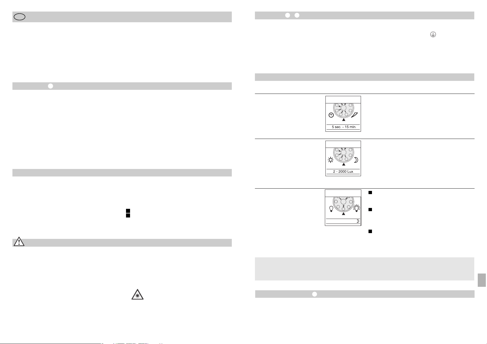
Instalacija –
Mjesto montaže trebalo bi biti udaljeno najmanje
50 cm od drugog svjetla jer toplinsko zračenje
može dovesti do aktiviranja sustava. Da bi se postigao domet od maks 12 m, visina montaže treba iznositi oko 2 m. Uređaj montirajte na čvrstoj podlozi kako
biste izbjegli pogrešna uključivanja.
Mrežni vod sastoji se od trožilnog kabela:
- 83 -
Funkcije
Kašnjenje isključivanja
(podešavanje vremena)
(tvornički podešeno: 5 sek)
Kontinuirano podesivo trajanje svjetla od 5 sek – 15 min
Regulator podešen na 1 (lijevi graničnik) =
najkraće vrijeme (5 sek)
Regulator podešen na 6 (desni graničnik) =
najduže vrijeme (15 min)
Kod podešavanja područja detekcije preporučujemo
odabir najkraćeg vremena 1.
Osnovna svjetloća
(tvornički podešeno: program 1)
Reflektor UKLJUČEN kao odgovor na kretanje
u području senzora od noćnog režima rada /
bez osnovne svjetloće.
Reflektor UKLJUČEN kao odgovor na kretanje
u području senzora od noćnog režima rada /
osnovna svjetloća reflektora (10%) 10 min nakon
isteka podešenog vremena.
Reflektor UKLJUČEN kao odgovor na kretanje
u području senzora od noćnog režima rada /
osnovna svjetloća od 10% uključena cijelu noć.
Podešavanje svjetlosnog praga
(prag aktiviranja)
(tvornički podešeno:
danje svjetlo 2000 luksa)
Kontinuirano podesiv prag aktiviranja senzora
od 2 – 2000 luksa.
Regulator podešen na 1 (lijevi graničnik) =
danje svjetlo oko 2000 luksa.
Regulator podešen na 6 (desni graničnik) =
noćni režim oko 2 luksa.
Za podešavanje područja detekcije kod danjeg svjetla
regulator treba staviti u položaj 1 (danje svjetlo).
LED 10% OFF / 10 min. / ~
1
2
3
Sve funkcije mogu se podesiti kad je prstenasti
zaslon izvučen.
Što je osnovna svjetloća ?
Osnovna svjetloća omogućava osvjetljavanje s oko
10 % svjetlosnog učina. Tek kod pokreta u području
detekcije svjetlo se uključuje (na podešeno vrijeme,
vidi Kašnjenje isključivanja ) na maksimalni učin
(100 %). Zatim se svjetlo na 10 min uključuje na
osnovnu svjetloću (oko 10 %).
Podešavanje dometa
Po potrebi se područje detekcije može optimizirati.
Priloženi pokrovni zasloni služe za prekrivanje segmenata leće po volji, odnosno za individualno skraćivanje dometa. Na taj način se izbjegavaju pogrešna
uključivanja zbog prolaska automobila, prolaznika itd.
i ciljano se nadziru mjesta opasnosti. Pokrovni zasloni
mogu se odrezati duž podjela označenih utorima u
okomitom ili vodoravnom položaju ili se mogu odrezati škarama. Nakon odvajanja prstenastog zaslona
treba ih objesiti u gornjem području senzorske leće.
Nakon toga ponovno nataknite prstenasti zaslon i na
taj način će se pokrovni zasloni čvrsto usaditi.
Okretanjem kućišta senzora za 80° moguće je fino
podešavanje senzora.
L = faza (većinom crna ili smeđa)
N = neutralni vodič (većinom plavi)
PE = zaštitni vodič (zeleno/žuti)
Važno: Slučajna zamjena priključaka u uređaju ili
Vašem ormariću za osigurače kasnije može uzrokovati
kratki spoj. U tom slučaju moraju se identificirati pojedinačni kabeli i ponovno montirati. U mrežnom vodu
može biti instalirana prikladna mrežna sklopka za
UKLJUČIVANJE i ISKLJUČIVANJE.
- 82 -
Uputa za montažu
Poštovani kupče,
zahvaljujemo na povjerenju koje ste nam ukazali
kupnjom Vaše nove STEINEL-ove senzorske LED
svjetiljke. Odlučili ste se za proizvod visoke kvalitete
koji je proizveden, ispitan i zapakiran s velikom
pažnjom.
HR
Sigurnosne upute
■ Prije svih radova na uređaju prekinite naponsko
napajanje!
■ Kod montaže električni vod koji namjeravate priključiti mora biti u beznaponskom stanju. Zbog toga
najprije isključite struju i pomoću ispitivača napona
provjerite je li uspostavljeno beznaponsko stanje.
■ Kod instalacije ovog uređaja radi se o radu na
mrežnom naponu; zbog toga se ona mora izvršiti
stručno i u skladu s državnim propisima o instalacijama i uvjetima priključivanja (D-VDE 0100,
A
-ÖVE/ÖNORM E 8001-1, -SEV 1000)
Molimo Vas da se prije njegovog instaliranja upoznate
s ovim uputama za montažu. Samo stručna instalacija
i puštanje u pogon jamče dug i pouzdan rad bez
smetnji.
Želimo Vam puno zadovoljstva s Vašom novom
STEINEL-ovom senzorskom LED svjetiljkom.
■ Nemojte montirati uređaj na inače lakozapaljive
površine.
■ Prikladna za unutrašnje i vanjske prostore.
■ Senzorska LED svjetiljka predviđena je samo
za zidnu montažu a ne za montažu na strop.
■ Kućište svjetiljke zagrijava se tijekom rada.
Poravnavanje LED glave provedite samo kad
se ohladi.
■ Ne gledajte u LED svjetiljku s kratke
udaljenosti ili duže vrijeme (> 5 min.). To
može uzrokovati oštećenje mrežnice oka.
Princip rada
Pokret uključuje svjetlo, alarm i ostalo. Za Vašu udobnost, za Vašu sigurnost. Bez obzira koristi li se u privatnom području za osvjetljenje kuće ili zemljišta, ili
u komercijalnom području npr. kao rasvjeta za teren
tvrtke, ova senzorska LED svjetiljka posvuda se brzo
montira i spremna je za rad.
Senzorske LED svjetiljke XLed 10 i XLed 25 opremljene su s dva pirosenzora od 120° koji detektiraju
nevidljivo toplinsko zračenje tijela koja se pred njima
kreću (ljudi, životinje itd.). Tako detektirano toplinsko
zračenje elektronički se pretvara u signal koji uključuje
svjetiljku. Zbog prepreka, kao što je npr. zid ili staklo,
senzor ne prepoznaje toplinsko zračenje. Pomoću
dva pirosenzora postiže se kut detekcije od 240° s
kutom otvora od 180°.
Važno: Najsigurniju detekciju pokreta postižete kad
se uređaj montira bočno na smjer kretanja i nikakve
prepreke (kao npr. drveća, zidovi itd.) ne ometaju
vidokrug senzora.
Opis uređaja
LED glava u flat dizajnu
Krak
Otvori za hlađenje
Zidni držač s mrežnim dijelom
Senzorska jedinica
Brtveni čepovi
Pokrovni zasloni
Princip rada
Podešavanje vremena
Podešavanje svjetlosnog praga
Podešavanje osnovne svjetloće
Podešavanje dometa/Podešavanje područja
detekcije
Funkcija stalnog svjetla
Mrežni priključak za podžbukni vod
Mrežni priključak za nadžbukni vod
I
II
HR
Page 43

- 85 -
Jamstvo funkcionalnosti
Ovaj Steinel-ov proizvod izrađen je uz veliku pažnju,
njegovo funkcioniranje i sigurnost ispitani su prema
važećim propisima i na kraju je proizvod podvrgnut
kontroli uzorka. STEINEL preuzima jamstvo za besprijekornu kakvoću i funkcionalnost.
Jamstveni rok iznosi 36 mjeseci a započinje s danom
prodaje potrošaču. Uklanjamo nedostatke koji su
posljedica grešaka na materijalu ili tvorničke greške,
realizacija jamstva izvršava se popravkom ili zamjenom dijela s greškom po našem izboru. Jamstvo ne
dajemo u slučaju oštećenja na potrošnim dijelovima,
kao i šteta i nedostataka koji nastanu zbog nestručnog rukovanja ili održavanja. Posljedične štete na
drugim predmetima su isključene.
Jamstvo se priznaje samo ako nerastavljeni, dobro
zapakiran uređaj pošaljete zajedno s kratkim opisom
greške i računom (datum kupnje i pečat trgovine),
nadležnoj servisnoj službi.
Servis za popravke:
Nakon isteka jamstvenog roka ili kad
se utvrdi nedostatak bez jamstva,
popravak će se izvršiti u tvornici.
Molimo da dobro zapakiran proizvod
pošaljete najbližoj servisnoj službi.
Izjava o sukladnosti
Ovaj proizvod ispunjava zahtjeve odredbe EU o
niskom naponu 2006/95/EG, o elektromagnetnoj
podnošljivosti (EMV) 2004/108/EG i odredbe o
ograničenju korištenja određenih opasnih materijala
u električnim i elektroničkim uređajima (RoHS)
2002/95/EG.
Smetnje u radu
Senzorska LED svjetiljka
je bez napona
Senzorska LED svjetiljka
se ne uključuje
Senzorska LED svjetiljka
se ne isključuje
Senzorska LED svjetiljka neželjeno
se uključuje.
Smetnja
■ neispravan osigurač, nije uključena, prekinut vod
■ kratki spoj
■ stavite novi osigurač, uključite
mrežnu sklopku; provjerite vod
pomoću ispitivača napona
■ provjerite priključak
■ kod pogona danju, svjetlosni
prag je podešen na noćni režim
rada
■ mrežna sklopka ISKLJUČENA
■ neispravan osigurač
■ područje detektiranja nije ciljano
podešeno
■ ponovno podesiti
■ uključiti
■ stavite novi osigurač, event.
provjerite priključak
■ ponovno podesiti
■ stalno kretanje u području
detekcije
■ kontrolirati područje i event.
iznova podesiti odnosno pokriti
■ vjetar njiše drveća i grmlje u
području detekcije
■ detektiranje automobila na cesti
■ iznenadna promjena tempera-
ture zbog nevremena (vjetar,
kiša, snijeg) ili zraka koji izlazi
iz ventilatora, otvorenih prozora
■ senzorska LED svjetiljka se
pomiče npr. zbog jakog
vjetra ili velikih oborina
■ premjestite područje
■ premjestite područje
■ promijenite područje,
premjestite mjesto montaže
■ senzorsku LED svjetiljku
montirajte na čvrstu podlogu
Uzrok Pomoć
Senzorska LED svjetiljka uvijek se
UKLJUČUJE/ISKLJUČUJE
■ životinje se kreću u području
detekcije
■ senzor zakrenuti naviše odnosno
ciljano pokriti; premjestite
odnosno pokrijte područje
- 84 -
Rad i njega
Ovaj uređaj nije prikladan za specijalne alarmne uređaje protiv krađe jer nema za to propisanu sigurnost
od sabotaže. Vremenski utjecaji mogu djelovati na
funkcioniranje senzorske LED svjetiljke. Kod jakog
vjetra, snijega, kiše, ili tuče može doći do pogrešnog
uključivanja jer se ne mogu razlikovati iznenadna
kolebanja temperature izvora topline.
Leća za detekciju može se u slučaju zaprljanosti
obrisati vlažnom krpom (bez sredstva za čišćenje).
Funkcija ručnog upravljanja
Montira li se mrežna sklopka u vod, osim jednostavne
funkcije uključivanja i isključivanja moguće su i
sljedeće funkcije:
Pogon senzora
1) Uključite svjetlo (ako je svjetlo ISKLJUČENO):
Sklopku 1 x ISKLJUČITI i UKLJUČITI.
LED-ovi ostaju uključeni tijekom podešenog vremena.
2) Isključite svjetlo (ako je svjetlo UKLJUČENO):
Sklopku 1 x ISKLJUČITI i UKLJUČITI.
Svjetiljka se isključuje odnosno prelazi u pogon
senzora.
Pogon stalnog svjetla
1) Uključite stalno svjetlo:
Sklopku 2 x ISKLJUČITI i UKLJUČITI. Svjetiljka je
podešena na 4 sata na stalno svjetlo (svijetli crvena
LED dioda iza leće). Zatim ponovno automatski
prelazi u pogon senzora (crvena LED dioda se
isključuje).
2) Isključivanje stalnog svjetla:
Sklopku 1 x ISKLJUČITI i UKLJUČITI. Svjetiljka se
isključuje odnosno prelazi u pogon senzora.
Važno:
Treba više puta uzastopce brzo pritiskati sklopku
(u području 0,5 – 1 sek).
Tehnički podaci
Senzorska LED svjetiljka XLed 10 XLed 25
Snaga: 10 LED-ova, oko 25 W 25 LED-ova, oko 60 W
Boja svjetla: oko 4000 Kelvina (topla bijela) oko 4000 Kelvina (topla bijela)
Svjetlosna struja: 960 lumena 2120 lumena
Dodatna uklopna snaga:
žarulje, maks. 800 W kod 230 V AC
fluorescentne cijevi, maks. 400 W kod cos ϕ = 0,5,
induktivno opterećenje kod 230 V AC
fluorescentne cijevi, štedne žarulje, LED svjetiljke s elektroničkom
predspojnom napravom kod 230 V AC,
4 x maks. po 60 W, C ≤ 88 µF
Vijek trajanja LED dioda: do 50000 sati (uz korištenje do 50000 sati (uz korištenje
3 sata/dan oko 45 godina) 3 sata/dan oko 45 godina)
Kut detekcije: 240° sa zaštitom od skrivanja 240° sa zaštitom od skrivanja
Projicirana površina 250 cm2+ 103,36 cm
2
420 cm2+ 103,36 cm
2
Zakretno područje
senzorske jedinice: ± 80°±80°
Zakretno područje kućišta: vertikalno 200° vertikalno 200°
horizontalno 270° horizontalno 270°
Podešavanje vremena: 5 sek – 15 min 5 sek – 15 min
Podešavanje svjetlosnog praga: 2 – 2000 luksa 2 – 2000 luksa
Regulacija svjetloće: 10% osnovne svjetloće (oko 3 W) 10% osnovne svjetloće (oko 6 W)
Stalno svjetlo: podesivo 4 sata podesivo 4 sata
Dimenzije (V x Š x D) 205 x 200 x 220 mm 300 x 200 x 220 mm
Te žina: 2200 g 2960 g
Temperaturno područje: -20 °C do +50 °C -20 °C do +50 °C
Vrsta zaštite: IP 44 IP 44
Klasa zaštite: I I
HR
Page 44

Installatsioon –
Montaažikoht peaks asuma teistest valgustitest
vähemalt 50 cm kaugusel, et vältida süsteemi sisse-
lülitumist soojuskiirguse tõttu. Antud 12-meetrise
ulatuspiirkonna saavutamiseks tuleb seade paigaldada
maks 2 m kõrgusele. Valelülituste vältimiseks monteerige seade kindlale aluspinnale.
Võrgujuhe koosneb 3-soonelisest kaablist:
- 87 -
Funktsioonid
Väljalülitamise viivitus
(kellaaja seadmine)
(tehaseseadistus: 5 s)
Astmeteta seadistatav sisselülitus kestvusega 5 s kuni
15 min.
Seadistuse regulaator reguleeritud 1
(vasakule keeramine) peale = lühim aeg (5 s)
Seadistuse regulaator reguleeritud 6
(paremale keeramine) peale = pikim aeg (15 min)
Jälgitava ala reguleerimiseks soovitame valida
lühima aja 1.
Põhivalgustus
Tehaseseadistus: programm 1)
Kiirgur SISSE liikumisel alates seadistatud
hämarusväärtusest / põhivalgustus puudub.
Kiirgur SISSE liikumisel alates seadistatud
hämarusväärtusest / + põhivalgustus (10%)
10 minutiks pärast seadistatud aja möödumist.
Lamp on SISSE lülitatud, kui tuvastab liikumise
alates seadistatud hämarusväärtusest / + põhiheledus (10%) kogu öö.
Hämarusnivoo seadistamine
(reaktsioonilävi)
(Tehaseseadistus:
päevavalgusrežiim 2000 luksi)
Astmeteta reguleeritav anduri reaktsiooni lävi:
2 kuni 2000 luksi.
Reguleerimisnupp 1 (vasakule keeramine) peal =
töö päevavalguses (u 2000 luksi).
Reguleerimisnupp 6 (paremale keeramine) peal =
töö päevavalguses (u 2 luksi).
Päevavalguses jälgitava ala reguleerimiseks tuleb reguleerimisnupp keerata 1 peale (töö päevavalguses).
LED 10% OFF / 10 min. / ~
1
2
3
Kõiki funktsioone on võimalik seadistada, kui
ümarsirm on maha võetud.
Mis on põhivalgustus?
Põhivalgustus võimaldab pidevat öist valgustust
umbes 10%-se valgustusvõimsusega. Valgus lülitub
alles jälgitaval alal liikumise korral (sätestatud ajaks,
vt väljalülitamise viivitus i) maksimaalsele valgustusvõimsusele (100%). Pärast seda lülitub lamp tagasi
põhivalgustusele 10 (umb 10%).
Tööraadiuse seadmine/häälestamine
Vastavalt vajadusele saate Te optimeerida jälgitavat ala.
Kaasasolevate katikute abil on võimalik ükskõik kui
palju läätsesegmente kinni katta või mõõtepiirkonda
individuaalselt vähendada. See võimaldab valelülituste
ärahoidmist nt autode, möödakäijate vms tõttu või ohtlike kohtade sihilikku valvet. Katikuid võib murda piki
ettevalmistatud vertikaalseid või horisontaalseid sooni
või lõigata kääride abil. Pärast ümarsirmi äravõtmist
tuleb see riputada anduriläätse ülemisse ossa. Seejärel
paigaldage ümarkatik uuesti kohale, et selle abil katikud tugevasti kohale kinnitada.
Anduri korpust ± 80° kraadi võrra keerates on lisaks
veel täpsem reguleerimine võimalik.
L = faas (enamasti must või pruun)
N = neutraaljuht (enamasti sinine)
PE = kaitsejuhe (roheline/kollane)
Tähtis! Ühenduste äravahetamine põhjustab hiljem
lühise seadmes või kaitsekapis. Sellisel juhul tuleb
kaablid kindlaks teha ja uuesti monteerida. Võrgujuhtmesse on loomulikult võimalik monteerida võrgulüliti
SISSE ja VÄLJA lülitamiseks.
- 86 -
Montaažijuhend
Väga austatud klient!
Täname Teid usalduse eest, mida Te meile uue
STEINELi sensoriga LED-kiirguri ostmisega osutasite.
Te otsustasite väärtusliku kvaliteettoote kasuks, mis
on valmistatud, testitud ja pakitud suurima hoolega.
Palun tutvuge enne installeerimist käesolevas monta-
EST
Ohutusjuhised
■ Enne seadme juures tööde alustamist lülitage vool
välja!
■ Paigaldamise ajal peab ühendatav elektrijuhe olema
pingevaba. Sellepärast tuleb kõigepealt välja lülitada
elektrivool ja kontrollida pingetestri abil, et juhe oleks
pingevaba.
■ Nende seadmete paigaldamisel on tegemist tööga
vooluvõrgus, mida peab seetõttu õigesti ja vastavalt
riigi paigaldusseadustele läbi viima (D-VDE 0100,
A
-ÖVE/ÖNORM E 8001-1, -SEV 1000)
ažijuhendiga. Ainult asjakohase paigalduse ja
kasutuselevõtuga tagatakse seadme pikaajaline,
usaldusväärne ja häireteta töö.
Soovime Teile meeldivat STEINELi infrapunaanduri
kasutamist.
■ Ärge monteerige seadet tavaliselt kergesti süttivatele
pindadele.
■ Sobiv välis- ja siseruumidele.
■ LED-anduriga prožektorid on ette nähtud ainult
monteerimiseks seinale ja mitte monteerimiseks
lakke.
■ Prožektori korpus läheb töö ajal väga kuumaks.
Seetõttu reguleerige LED-pead alles pärast selle
mahajahtumist.
■ Ärge vaadake lähedalt või pikemat aega
(> 5 min) LED-lambi sisse. See võib
kahjustada silma võrkkesta.
Printsiip
Liikumine lülitab sisse valguse, alarmi või muu funktsiooni. See on Teie mugavuse ja turvalisuse tagamiseks. Kas eravalduses maja ja krundi valgustamiseks
või ettevõttes nt firma maa-ala valgustamiseks - sensoriga LED-kiirgurid on igal pool kiiresti paigaldatavad
ja töövalmis.
Sensoriga LED-kiirgurid XLed 10 ja XLed 25 on kahe
120° pürosensoriga varustatud, mis tuvastavad liikuvate kehade (inimesed, loomad jne) soojuskiirgust.
Sellisel viisil registreeritud soojuskiirgus muundatakse
elektrooniliselt ning kiirgur lülitub sisse. Takistused,
näiteks müürid või klaasplaadid ei lase soojuskiirgust
läbi. Kahe pürosensor abil saavutatakse 240°
tuvastusnurk avatusnurgaga 180°.
Tähtis! Liikumise usaldusväärseima tuvastuse saavutate siis, kui monteerite seadme kõndimise suuna
suhtes küljele ning takistused (nt puud, müürid) ei
piira sensori vaatevälja.
Seadme kirjeldus
LED-pea Flat-disainiga
Liigendhaar
Jahutusribid
Võrgualaldi seinahoidik
Sensorimoodul
Tihendusprunt
Kattekestad
Printsiip
Ajaregulaator
Hämaruse seadistus
Põhivalgustuse seadistamine
Tööraadiuse seadmine /
tuvastuspiirkonna häälestamine
Püsivalguse funktsioon
Võrgutoitejuhe süvispaigalduseks
Võrgutoide pindpaigalduseks
I
II
EST
Page 45
- 89 -
Talitlusgarantii
See Steineli toode on valmistatud suurima hoolega,
kontrollitud töökindluse ja ohutuse osas kehtivate
eeskirjade kohaselt ning seejärel läbinud pistelise
kontrolli. Steinel annab garantii toote laitmatu kvaliteedi ja töökorras oleku kohta.
Garantiiaeg on 36 kuud ja see algab tarbijale toote
ostmise päevast. Meie remondime materjalist või
tootmisvigadest tulenevad puudused, garantiijuhtumi
korral seade kas remonditakse või puudulik osa asendatakse uuega, valiku üle otsustame meie. Garantii ei
kehti kuluvate osade ning kahju ja puuduste kohta,
mis on tekkinud oskamatu käsitsemise või hoolduse
tagajärjel. Kaugemale ulatuvad kaudsed kahjud kõrvaliste esemete suhtes on välistatud.
Garantiiremonti tehakse ainult siis, kui lahtivõtmata
seade saadetakse koos vea lühikirjelduse, kassatšeki
või arvega (ostmise kuupäev ja kaupluse tempel) ja
korralikult pakituna vastavasse teeninduspunkti.
Remonditeenus.
Pärast garantiiaja möödumist või
puuduste korral, mille kohta garantii
ei kehti, remondib seadme meie
tehase teeninduspunkt. Palun saata
korralikult pakendatud seade lähimasse teeninduspunkti.
Vastavusdeklaratsioon
Toode vastab madalpingedirektiivile 2006/95/EÜ,
elektromagnetilise ühilduvuse direktiivile 2004/108/EÜ
ja ohtlike ainete kasutamise piiramise direktiivile
(RoHS) 2002/95/EÜ.
Häired seadme töös
Sensoriga LED-kiirgur
ilma pingeta
Sensoriga LED-kiirgur
ei lülitu sisse
Sensoriga LED-kiirgur
ei lülitu välja
Sensoriga LED-kiirgur
lülituvad soovimatult sisse
Rike
■ kaitse on defektne, ei ole sisse
lülitatud, elektrijuhe katkenud
■ lühis
■ uus kaitse, lülitage võrgulüliti
sisse; kontrollige juhet
pingetestriga
■ kontrollige ühendusi
■ päevasel ajal on hämarus-
regulaator öörežiimil
■ võrgulüliti on VÄLJA lülitatud
■ kaitse defektne
■ jälgitav ala pole sihipäraselt
kohandatud
■ reguleerige uuesti
■ lülitage sisse
■ uus kaitse, vajaduse korral
kontrollige ühendust
■ kohaldage ala uuesti
■ pidev liikumine jälgitaval alal ■ kontrollige ala ja kohaldage see
vajaduse korral uuesti või katke
ala kinni
■ tuul liigutab puid ja põõsaid
jälgitaval alal
■ seade registreerib autosid
tänaval
■ järsk temperatuurimuudatus
ilmastiku (tuule, vihma, lume)
või ventilaatorite heitõhu,
avatud akende tõttu
■ LED-aduriga prožektor kõigub
(liigub) nt tuulepuhangute või
tugevate sademehoogude tõttu
■ kohandage ala uuesti
■ kohandage ala uuesti
■ muutke ala, monteerige seade
teise kohta
■ paigaldage LED-anduriga prožektor kindlale aluspinnale
Põhjus Abi
Sensoriga LED-kiirgur
lülituvad alati SISSE/VÄLJA
■ jälgitaval alal liiguvad loomad ■ pöörata andur kõrgemale
või katta teatud suunas kinni;
seadke piirkond ümber või
katke kinni
- 88 -
Käitamine ja hooldus
Seade ei sobi kasutamiseks spetsiaalsetes sissemurdmisvastastes alarmseadmetes, sest tal puudub
selleks nõutav sabotaažikaitse. Ilmastikutingimused
võivad sensoriga LED-kiirguri funktsiooni mõjutada.
Tugevad tuulepuhangud, lumi, vihm, rahe võivad
põhjustada valekäivituse, sest seade ei eralda järske
temperatuurimuutusi soojusallikatest.
Tuvastusläätse võib mustumise korral puhastada
niiske lapiga (ilma puhastusvahenditeta).
Pideva valgustuse funktsioon
Kui võrgujuhtmesse monteerida võrgulüliti, on lihtsalt
sisse- ja väljalülitamise kõrval võimalikud järgnevad
funktsioonid.
Sensorirežiim
1) Valguse sisselülitamine
(kui kiirgur on VÄLJA lülitatud):
lüliti 1 x VÄLJA ja SISSE.
LED-id jäävad seadistatud ajaks sisse.
2) Valguse väljalülitamine
(kui kiirgur SISSE lülitatud):
lüliti 1 x VÄLJA ja SISSE.
Kiirgur lülitub välja või sensorirežiimile.
Pideva valgustuse režiim
1) Pideva valgustuse sisselülitamine:
lüliti 2 x VÄLJAS ja SEES. Prožektor lülitatakse 4 tunniks
pideva valgustuse režiimi (läätse taga asuv punane LED
põleb). Seejärel lülitub see automaatselt uuesti ümber
andurirežiimi (punane LED väljas).
2) Pideva valgustuse väljalülitamine:
lüliti 1 x VÄLJA ja SISSE. Prožektor lülitub välja või
ümber andurirežiimi.
Tähtis!
Lüliti mitmekordne vajutamine peab toimuma kiiresti
(0,5 – 1 s vahel).
Tehnilised andmed
Sensoriga LED-kiirgur XLed 10 XLed 25
Võimsus: 10 x LED, ca 25 W 25 x LED, ca 60 W
Valgusvärvus: u 4000 kelvinit (soe-valge) u 4000 kelvinit (soe-valge)
Valgusvoog: 960 luumenit 2120 luumenit
Täiendav lülitusvõimsus:
hõõglambid, max 800 W 230 V AC juures
luminofoortoru, max 400 W cos ϕ = 0,5 juures,
induktiivne koormus 230 V AC juures
luminofoorlambid, energiasäästulambid,
elektroonilise eellülitusseadmega LED-lambid 230 V AC juures,
4 x max igaüks 60 W, C ≤ 88 µF
LED-ide kasutusiga: kuni 50 000 tundi, kuni 50 000 tundi.
(3 tunni puhul päevas u 45 aastat) (3 tunni puhul päevas u 45 aastat)
Tuvastusnurk: 240° alt läbiroomamise kaitsega 240° alt läbiroomamise kaitsega
Projitseeritud pind 250 cm2+ 103,36 cm
2
420 cm2+ 103,36 cm
2
Sensorimooduli pöördepiirkond: ± 80° ± 80°
Korpuse pöördeulatus: vertikaalne 200° vertikaalne 200°
horisontaalne 270° horisontaalne 270°
Ajaregulaator: 5 s – 15 min 5 s – 15 min
Hämarusnivoo reguleerimine: 2 – 2000 luksi 2 – 2000 luksi
Heleduse reguleerimine: 10% põhivalgustus (umbes 3 W) 10% põhivalgustus (umbes 6 W)
Püsivalgus: 4 tunniks seadistatav 4 tunniks seadistatav
Mõõdud (K x L x S): 205 x 200 x 220 mm 300 x 200 x 220 mm
Kaal: 2200 g 2960 g
Temperatuurivahemik: -20 °C kuni +50 °C -20 °C kuni +50 °C
Kaitseliik: IP 44 IP 44
Kaitseklass: I I
EST
Page 46
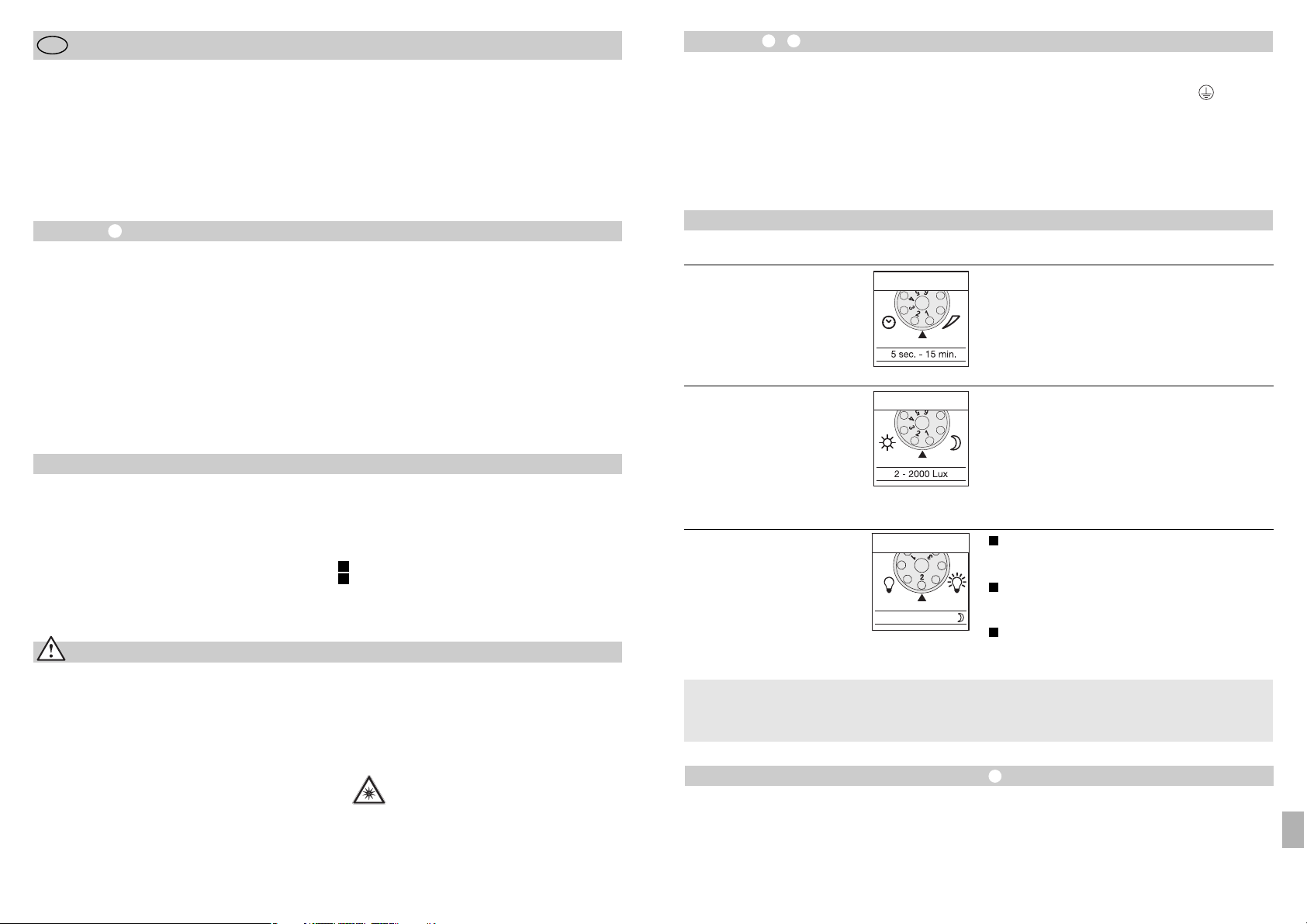
Įrengimas –
Montavimo vieta turėtų būti nutolusi nuo kito šviestuvo bent 50 cm, nes jo skleidžiama šiluma
gali įjungti sistemą. Siekiant užtikrinti maksimalią 12 m
jautrumo zoną, montuoti reikėtų apie 2 m aukštyje.
Kad prietaisas neįsijungtų nepageidaujamu metu,
montuokite jį ant tvirto pagrindo.
Tinklo išvadą sudaro trigyslis kabelis:
- 91 -
Funkcijos
Švietimo trukmės nustatymas
(Gamyklos nustatymas: 5 sek.)
Tolygiai nustatoma švietimo trukmė nuo 5 sek. iki 15 min.
Nustatymo reguliatorius nustatomas ties 1 (kairėje) =
trumpiausias laikas (5 sek.)
Nustatymo reguliatorius nustatomas ties 6 (dešinėje) =
ilgiausias laikas (15 min.)
Nustatant prožektoriaus jautrumo zoną rekomenduojama
pasirinkti trumpiausią švietimo laiką 1.
„Budintis“ režimas
(Gamyklos nustatymas:
programa 1)
Prožektorius įsijungia užfiksavęs judesį esant
nustatytam prieblandos lygiui / be „budinčiojo“
režimo.
Prožektorius įsijungia užfiksavęs judesį esant
nustatytam prieblandos lygiui / + „budintis“
režimas (10 %) 10 min. pasibaigus laikui.
ĮSIJUNGIA užfiksavus judesius esant nustatytam
prieblandos lygiui / + „budintis“ režimas (10 %)
visą naktį.
Prieblandos lygio nustatymas
(Suveikimo slenkstis)
(Gamyklos nustatymas:
„dienos“ režimas 2000 liuksų)
Tolygiai nustatomas sensoriaus suveikimo temstant
slenkstis nuo 2 iki 2000 liuksų.
Nustatymo reguliatorius ties 1 (kairėje) =
dienos šviesos režimas (apie 2000 liuksų).
Nustatymo reguliatorius ties 6 (dešinėje) =
prieblandos režimas (apie 2 liuksus).
Nustatant jautrumo zoną dienos šviesoje, nustatymo
reguliatorius turi būti nustatytas ties 1 (dienos šviesos
režimas).
LED 10% OFF / 10 min. / ~
1
2
3
Visas fukcijas galima nustatyti nuėmus
apatinį sensoriaus žiedelį.
Kas yra „budintis“ režimas?
„Budintis“ režimas – tai pastovus apšvietimas maždaug 10 % galingumu. Tik užfiksavus judesius sensoriaus jautrumo zonoje, šviesa įsižiebs (nustatytam
laikui, žr. skyrių „Išjungimo vėlinimas“ ) visu
galingumu (100 %). Po to prožektorius vėl 10 min.
persijungs į „budintį“ režimą (apie 10 %).
Jautrumo zonos nustatymas (reguliavimas)
Esant poreikiui apimties kampą galima nustatyti optimaliau. Pridėtomis dengiamosiomis užsklandomis
galima uždengti sensoriaus linzės dalį arba sutrumpinti jautrumo zonos ilgį. Taip išvengiama žibinto įsijungimo nepageidaujamu metu, pvz., dėl pravažiuojančių automobilių, praeivių ir t. t., arba tikslingai stebimos pavojingos vietos. Užsklandos gali būti atskiria-
mos ar kerpamos žirklėmis pagal linijas statmenai ar
lygiagrečiai. Nuėmus apatinį sensoriaus žiedelį, jas
reikia įtvirtinti viršutinėje sensoriaus linzės dalyje. Po
to žiedelį reikia vėl uždėti.
Sukdami sensoriaus korpusą ± 80° galite nustatyti
jį dar tiksliau.
L = fazė (dažniausiai juodas ar rudas laidas)
N = nulinis laidas (dažniausiai mėlynas)
PE = įžeminimo laidas (geltonas / žalias)
Svarbu! Neteisingai sujungti laidai sukelia trumpąjį
jungimą prie taise arba paskirs tymo spintoje. Tokiu
atveju reikia identifikuoti atitinkamus kabelius ir
sujungti juos iš naujo. Į tinklo įvadą galima įmontuoti
tinkamą tinklo jungiklį, kuris atliks įjungimo ir išjungimo
funkcijas.
- 90 -
Montavimo instrukcija
Gerb. kliente,
dėkojame, kad parodėte pasitikėjimą ir įsigijote naująjį
STEINEL sensorinį šviesos diodų prožektorių. Jūs
įsigijote aukštos kokybės produktą, kuris pagamintas,
išbandytas ir supakuotas ypač kruopščiai.
LT
Saugos reikalavimai
■ Prieš pradėdami dirbti su prietaisu, atjunkite
elektros įtampą!
■ Montuojant prijungiamajame elektros laide neturi
būti įtampos. Todėl visų pirma atjunkite elektros
srovę ir įtampos indikatoriumi patikrinkite, ar nėra
įtampos.
■ Šie prietaisai jungiami prie elektros tinklo;
todėl jį reikia prijungti tinkamai, vadovaujantis
šalyje galiojančiomis in stal iacijos normomis
ir jungimo taisyklmis (D-VDE 0100,
A
-ÖVE/ÖNORM E 8001-1, -SEV 1000)
Prieš prijungdami prietaisą susipažinkite su šia montavimo instrukcija. Nes tik taisyklingai prijungtą ir tinkamai pradėtą naudoti prietaisą galėsite eksploatuoti
ilgai, patikimai ir be gedimų.
Linkime malonių akimirkų naudojantis savo naujuoju
STEINEL sensoriniu šviesos diodų prožektoriumi.
■
Nemontuokite prietaiso ant lengvai užsiliepsnojančių
paviršių.
■ Tinka naudoti lauke ir viduje.
■ Sensorinis šviesos diodų prožektorius skirtas
montuoti tik ant sienų, o ne ant lubų.
■ Prožektoriaus korpusas darbo metu labai įkaista.
Prieš pasukdami šviesos diodų prožektorių kita
kryptimi, palaukite kol jis atvės.
■ Nežiūrėkite į LED šviestuvą iš arti arba
ilgą laiką (> 5 min.). Taip galite sužaloti
akies tinklainę.
Principas
Užfiksavus judesį įjungiama šviesa, signalizacija ir pan.
Jūsų patogumui, Jūsų saugumui. Nesvarbu, ar naudosite šį sensorinį šviesos diodų prožektorių privačioje
aplinkoje apšviesti savo namus ar sklypą, ar darbo
aplinkoje pvz., apšviesti įmonės teritoriją, šiuos
prietaisus greitai sumontuosite ir galėsite pradėti naudoti visur.
Sensoriniuose šviesos diodų prožektoriuose „XLed 10“
ir „XLed 25“ įmontuoti du 120° piroelementai, fiksuojantys nematomą judančių kūnų (žmonių, gyvūnų,
ir t. t.) skleidžiamą šilumą. Ši užfiksuota skleidžiama
šiluma paverčiama elektroniniais signalais, kurie įjungia
prožektorių. Kliūtys, pvz., sienos ar langai, trukdo užfiksuoti skleidžiamą šilumą. Su dviem piroelementais
pasiekiamas 240° apimties kampas esant 90° atverties
kampui.
Svarbu! Geriausiai judesys bus fiksuojamas tuomet,
kai prietaisas montuojant bus atsuktas šonu judėjimo
krypčiai ir sensoriaus jautrumo lauko neužstos kliūtys
(pvz., medžiai, sienos ir pan.).
Prietaiso aprašymas
Šviesos diodo plokščios galvutės konstrukcija
Šarnyrinė rankovė
Aušintuvas
Kronšteinas su maitinimo bloku
Sensorius
Sandariklis
Užuolaidėlės
Principas
Švietimo trukmės nustatymas
Prieblandos nustatymas
Ryškumo nustatymas
Jautrumo zonos ilgio nustatymas /
jautrumo zonos reguliavimas
Pastovaus švietimo funkcija
Potinkinis tinklo įvadas
Virštinkinis tinklo įvadas
I
II
LT
Page 47
- 93 -
Funkcijų garantija
Šis „Steinel“ produktas pagamintas itin kruopščiai,
pagal galiojančias normas patikrintos jo funkcijos ir
saugumas bei papildomai atlikta pasirinktų prietaisų
patikra. STEINEL suteikia prietaisui garantiją.
Garantinis laikotarpis – 36 mėnesiai. Jis prasideda
nuo prietaiso pardavimo vartotojui dienos. Mes pašalinsime defektus, susijusius su medžiagų arba gamybos broku; garantiniu laikotarpiu, mūsų nuožiūra,
prietaisas nemokamai remontuojamas arba keičiamos
sugedusios dalys. Garantija netaikoma susidėvinčioms dalims, taip pat jei prietaisas sugenda dėl
netinkamo naudojimo arba netinkamos priežiūros.
Pretenzijos dėl kitiems daiktams padarytos žalos
nepriimamos.
Garantija taikoma tik tuo atveju, jei neišardytas prietaisas kartu su kasos čekiu arba sąskaita (pirkimo
data ir pardavėjo antspaudu), tinkamai supakuotas
atsiunčiamas į atitinkamą techninės priežiūros tarnybos vietą.
Remonto servisas
Pasibaigus garantinio aptarnavimo
laikotarpiui arba atsiradus gedimams,
kuriems garantija netaikoma, prietaisą taiso mūsų gamyklos servisas.
Prašom gerai supakuotą produktą
atsiųsti į artimiausią servisą.
Atitikties deklaracija
Gaminys atitinka žemos įtampos direktyvą
2006/95/EB, elektromagnetinio suderinamumo
direktyvą 2004/108/EB ir taip pat direktyvą dėl
pavojingų medžiagų panaudojimo apribojimo
(RoHS) 2002/95/EB.
Veikimo sutrikimai
Sensorinis šviesos diodų
prožektorius be įtampos
Sensorinis šviesos diodų
prožektorius neįjungia šviestuvo
Sensorinis šviesos diodų prožektorius neišjungia šviestuvo
Sensorinis šviesos diodų prožektorius įsijungia nepageidaujamu metu
Sutrikimas
■ Perdegęs saugiklis; išjungtas
jungiklis; nutrauktas laidas
■ Trumpasis jungimas
■ Reikia naujo saugiklio; įjunkite
tinklo jungiklį; įtampos indikatorium patikrinkite liniją
■ Patikrinkite įvadą
■ Sensorius nustatytas „nakties“
režimui
■ Tinklo jungiklis IŠJUNGTAS
■ Perdegęs saugiklis
■ Jautrumo zona nustatyta
netiksliai
■ Nustatykite prieblandos lygį
iš naujo
■ Įjunkite jungiklį
■ Reikia naujo saugiklio arba
patikrinkite įvadą
■ Iš naujo sureguliuokite
■ Jautrumo zonoje fiksuojamas
nuolatinis judesys
■ Patikrinkite jautrumo zoną ir,
jei reikia, iš naujo ją nustatykite
arba pakeiskite
■ Jautrumo zonoje vėjas linguoja
medžius ir krūmus
■ Užfiksuojami gatve važiuojantys
automobiliai
■ Staigūs temperatūros svyravimai
dėl oro sąlygų (vėjo, lietaus,
sniego) arba ventiliatorių ar atvirų langų sukelto oro judėjimo
■ Sensorinis šviesos diodų prožektorius siūbuoja (juda) dėl,
pvz., vėjo gūsių ar stipraus lietaus (sniego, krušos).
■ Nustatykite kitą jautrumo zoną
■ Nustatykite kitą jautrumo zoną
■ Pakeiskite jautrumo zoną,
pakeiskite montavimo vietą
■ Sensorinį šviesos diodų
prožektorių pritvirtinkite ant
tvirto pagrindo
Priežastis Pagalba
Sensorinis šviesos diodų prožektorius nuolat įsijungia ir išsijungia
■ Jautrumo zonoje juda gyvūnai ■ Sensorių pakreipkite aukštyn
arba nustatykite tiksliau;
pakeiskite jautrumo zoną ar
nustatykite iš naujo
- 92 -
Naudojimas ir priežiūra
Specialioms įsilaužimo pavojaus signalizacijoms jis
netinka, nes neturi tam reikalingos apsaugos nuo
sabotažo. Oro permainos gali turėti įtakos šviesos
diodų prožektoriaus funkcijai. Esant stipriems vėjo
gūsiams, sningant, lyjant, krušos metu prietaisas gali
įsijungti nepageidaujamu metu, nes staigių temperatūros pokyčių neįmanoma atskirti nuo šilumos šaltinių.
Užsiteršusias linzes reikia valyti drėgnu audeklu
(nenaudoti jokių valiklių).
Pastovaus švietimo funkcija
Jei įvade įmontuotas tinklo jungiklis, be paprastų
įjungimo ir išjungimo galimos ir šios funkcijos:
Sensorinis režimas
1) Įjungti šviesą (kai prožektorius IŠJUNGTAS):
Jungiklį 1 x IŠJUNGTI ir ĮJUNGTI.
Šviesos diodas šviečia nustatytą laiko tarpą.
2) Išjungti šviesą (kai prožektorius ĮJUNGTAS):
Jungiklį 1 x IŠJUNGTI ir ĮJUNGTI.
Prožektorius išsijungia arba pereina į sensorinį
darbo režimą.
Pastovaus švietimo režimas
1) Pastovaus švietimo įjungimas:
Jungiklį 2 x IŠJUNGTI ir ĮJUNGTI. Prožektorius pereina į pastovų 4 valandų švietimo režimą (linzėje dega
raudonas šviesos diodas (LED)). Po to jis automatiškai
persijungia į sensorinį režimą (raudonas šviesos
diodas (LED) išsijungia).
2) Pastovaus švietimo išjungimas:
Jungiklį 1 x IŠJUNGTI ir ĮJUNGTI. Prožektorius
išsijungia arba pereina į sensorinį darbo režimą.
Svarbu!
Jungiklį reikėtų įjungti greitais vienas po kito
sekančiais judesiais (kas 0,5–1 sek.).
Techniniai duomenys
Sensorinis šviesos
diodų prožektorius XLed 10 XLed 25
Galingumas: 10 šviesos diodų, apie 25 W 25 šviesos diodų, apie 60 W
Šviesos spalva: maždaug 4000 kelvinų (šilta balta) maždaug 4000 kelvinų (šilta balta)
Šviesos srautas: 960 liumenų 2120 liumenų
Papildoma įjungimo galia:
kaitrinės lemputės, maks. 800 W esant 230 V AC
liuminescencinės lempos, maks. 400 W esant cos ϕ = 0,5,
induktyvi apkrova esant 230 V AC
liuminescencinės lempos, energiją taupančios lempos, LED
šviestuvai su elektroniniais paleidimo įrenginiais esant 230 V AC,
4 x maks. po 60 W, C ≤ 88 µF
Šviesos diodų eksploatavimo nuo 50 000 stand. nuo 50 000 stand.
trukmė: (3 val./dieną apie 45 metus) (3 val./dieną apie 45 metus)
Apimties kampas: 240° su apsauga nuo pasislėpimo 240° su apsauga nuo pasislėpimo
Projekcinis prožektoriaus plotas: 250 cm2+ 103,36 cm
2
420 cm2+ 103,36 cm
2
Sensoriaus pokrypio kampas: ± 80° ± 80°
Korpuso pakreipimo kampas: vertikaliai 200° vertikaliai 200°
horizontaliai 270° horizontaliai 270°
Švietimo trukmės nustatymas: 5 sek.–15 min. 5 sek.–15 min.
Šviesos stiprio nustatymas: 2–2000 liuksų 2–2000 liuksų
„Budintis“ režimas: 10 % „budintis“ režimas (apie 3 W) 10% „budintis“ režimas (apie 6 W)
Pastovus švietimas: 4 val. reguliuojamas 4 val. reguliuojamas
Matmenys (A x P x G) 205 x 200 x 220 mm 300 x 200 x 220 mm
Svoris: 2200 g 2960 g
Temperatūros diapazonas: nuo -20 °C iki +50 °C nuo -20 °C iki +50 °C
Saugos rūšis: IP 44 IP 44
Saugos klasė: I I
LT
Page 48

Instalēšana –
Ierīce montējama vismaz 50 cm attālumā no kāda cita
gaismekĮa, jo tā termiskais starojums var izraisīt neplānotu
sistēmas ieslēgšanos. Lai sasniegtu norādīto maksimālo
12 m aizsniedzamību, montāžas augstumam būtu jābūt
aptuveni 2 m. Ierīci montējiet uz cietas pamatnes, lai
novērstu neplānotu ieslēgšanos.
Tīkla pievadvadu veido 3 dzīslu kabelis:
- 95 -
Funkcijas
Izslēgšanās aizture
(laika iestatīšana)
(rūpnīcas iestatījums: 5 sek.)
Bez pakāpēm iestatāms degšanas ilgums no 5 sek. līdz 15 min.
Iestatījumu regulators uz 1 (kreisās puses gala pozīcija) =
īsākais laiks (5 sek.).
Iestatījumu regulators uz 6 (labās puses gala pozīcija) =
garākais laiks (15 min.).
Iestatot uztveres lauku, iesakāms izvēlēties īsāko laiku 1.
Bāzes gaismas iestatīšana
(rūpnīcas iestatījums: 1. programma)
Starmetis IESLĒDZAS pie kustības, sākot no iestatītās
krēslas vērtības / bez bāzes gaismas.
Starmetis IESLĒDZAS pie kustības, sākot no iestatītās
krēslas vērtības / + bāzes gaisma (10%) uz 10 min. pēc
iestatītā laika paiešanas.
Starmetis, uztverot kustību, pie iestatītās krēslošanas
vērtības / + bāzes gaisma (10 %) DEG visu nakti.
Krēslas sliekšņa iestatījums
(reakcijas slieksnis)
(rūpnīcas iestatījums:
dienasgaismas režīms 2000 luksi)
Bez pakāpēm iestatāms sensora reakcijas slieksnis no
2 līdz 2000 luksiem.
Iestatījumu regulators uz 1 (kreisās puses gala pozīcija) =
dienasgaismas režīms, aptuveni 2000 luksi.
Iestatījumu regulators uz 6 (labās puses gala pozīcija) =
krēslošanas režīms, aptuveni 2 luksi.
Iestatot uztveres lauku dienasgaismā, iestatījumu
regulatoram jābūt uz 1 (dienasgaismas režīms).
LED 10% OFF / 10 min. / ~
1
2
3
Visas funkcijas var iestatīt, noņemot blendi.
Kas ir bāzes gaisma?
Bāzes gaisma nodrošina apgaismojumu ar aptuveni 10 %
gaismas jaudu. Tikai notiekot kustībai uztveres laukā,
gaisma (uz iestatīto laiku, skat. Izslēgšanas aizture
),
tiek ieslēgta ar maksimālo gaismas jaudu (100 %).
Pēc tam gaismeklis uz 10 min. ieslēdzas bāzes
gaismas režīmā (aptuveni 10 %).
Aizsniedzamības iestatīšana / justēšana
Pēc vajadzības uztveres lauks var tikt ierobežots. Komplektācijā ietilpstošās nosegblendes kalpo nenoteikta skaita
lēcas segmentu nosegšanai, t. i., individuāla aizsniedzamības samazināšana. Tādejādi tiek novērsta kĮūdaina, piemēram, auto, gājēju u. c. izraisīta ieslēgšanās vai mērķtiecīgi
pārraudzītas riska zonas. Nosegblendes var atdalīt gar
horizontālo un vertikālo rievoto daĮu vai arī, nogriežot ar
šķērēm. Pēc blendes noņemšanas tās piestiprināmas
sensora lēcas augšējā daĮā. Pēc tam blende tiek uzlikta
atpakaĮ; tādejādi nosegblendes ir cieši nofiksētas. Grozot
sensora korpusu par ± 80°
, iespējama arī detalizētāka
noregulēšana.
L = fāze (visbiežāk melns vai brūns)
N = nulles vads (visbiežāk zils)
PE = zemējums (zaĮš/dzeltens)
Svarīgi: Pieslēgumu sajaukšana noved pie īssavienojuma
ierīcē vai Jūsu elektrības kastē. Šādā gadījumā veicama
atkārtota atsevišķu kabeĮu noteikšana un atkārtota montāža. Tīkla pievadvadā, var iemontēt atbilstošu tīkla slēdzi
IESLĒGŠANAI un IZSLĒGŠANAI.
- 94 -
Montāžas pamācība
Ļoti cienījamais klient!
Paldies par uzticēšanos, kuru mums izrādāt, iegādājoties
šo jauno STEINEL sensora LED starmeti. Jūs esat izvēlējies
augstvērtīgu, kvalitatīvu produktu, kurš ir izgatavots,
pārbaudīts un iepakots ar vislielāko rūpību.
LV
Norādījumi drošībai
■
Pirms darba ar ierīci pārtraukt sprieguma pievadi tai!
■
Montāžas laikā pievienojamais elektrības vads nedrīkst
atrasties zem sprieguma. TādēĮ vispirms atslēgt strāvas
padevi un ar sprieguma mērītāju pārbaudīt, vai vads
atrodas zem sprieguma.
■
Instalējot šo ierīci, jāstrādā ar elektrotīkla spriegumu.
Instalācija veicama lietpratīgi saskaņā ar vietējo instalēšanas un pieslēgšanas tehnisko priekšrakstu prasībām.
(
D
– VDE 0100, H– ÖVE/ÖNORM E8001-1, – SEV
1000).
Pirms instalēšanas lūdzam izlasīt šo montāžas pamācību.
Jo vienīgi lietpratīga montāža un lietošana nodrošina ilglaicīgu, drošu un nevainojamu darbību.
Mēs novēlam Jums daudz patīkamu mirkĮu kopā ar Jūsu
jauno STEINEL sensora LED starmeti.
■
Nemontējiet ierīci uz viegli uzliesmojošām virsmām.
■
Piemērota iekštelpām un ārpus telpām.
■
Sensora LED starmetis paredzēts tikai montāžai pie
sienas un nav paredzēts montāžai pie griestiem.
■
Starmeša korpuss darbības laikā uzsilst. LED galvas
regulēšanu veikt tikai, kad tā ir atdzisusi.
■
Neskatīties no tuva attāluma vai ilgstoši
(> 5 min) LED starmetī. Tas var novērst pie
tīklenes bojājumiem.
Princips
Kustība ieslēdz gaismu, signalizāciju un daudz ko citu. Jūsu
komfortam, Jūsu drošībai. Privātai vai industriālai lietošanai,
piemēram, uzņēmuma teritorijas apgaismošanai. Šis
sensora LED starmetis ir visur ātri uzmontējams un gatavs
lietošanai.
Sensora LED starmeši XLed 10 un XLed 25 ir aprīkoti ar
diviem 120° pirosensoriem, kuri uztver kustīgu ķermeņu
(cilvēku dzīvnieku u. c.) termisko starojumu. Šādā veidā
uztvertais starojums tiek elektroniski pārvērsts un ieslēdz
starmeti. Caur šķēršĮiem, piemēram, mūriem vai stikliem,
netiek uztverts termiskais starojums. Ar divu pirosensoru
palīdzību tiek sasniegts 240° liels uztveres leņķis ar 180°
atvēršanas leņķi.
Svarīgi: Visdrošāko kustības uztveri Jūs iegūsiet, ja ierīci
uzmontēsiet iesāņus kustības virzienam un sensora uztveri
neierobežos nekādi šķēršĮi (piem., koki, mūri utt.). Aizsniedzamība ir ierobežota, ja Jūs virzīsieties tieši uz sensoru.
Ierīces apraksts
plakana dizaina LED galva
grozāmā svira
dzesēšanas valnīši
sienas stiprinājums ar tīkla pievadu
sensora vienības drošības skrūve
blīvaizbāznis
nosegapvalki
princips
laika iestatīšana
krēslas sliekšņa iestatīšana
bāzes gaismas iestatīšana
aizsniedzamības iestatīšana/uztveres lauka justēšana
ilgstošā apgaismojuma funkcija
zemapmetuma strāvas pievadkabelis
virsapmetuma strāvas pievadkabelis
I
II
LV
Page 49

- 97 -
Darbības garantija
Šis STEINEL produkts ir izgatavots ar vislielāko rūpību, tā
darbība un drošība ir pārbaudīta saskaņā ar spēkā esošajiem priekšrakstiem, un noslēgumā pakĮauts izlases veida
pārbaudei. STEINEL garantē nevainojamas produkta īpašības un darbību. Garantijas laiks ir 36 mēneši un stājas spēkā ar pārdošanas dienu lietotājam. Mēs novēršam trūkumus, kuri radušies materiālu vai rūpnīcas kĮūdu dēĮ, garantijas serviss ietver sevī bojāto daĮu savešanu kārtībā vai
apmaiņu pēc mūsu izvēles. Garantijas serviss neattiecas uz
nodilumam pakĮauto daĮu bojājumiem, kā arī uz bojājumiem
un trūkumiem, kuri radušies nelietpratīgas lietošanas vai
apkopes rezultātā. Garantijas saistības neattiecas uz citiem
objektiem, kas varētu tikt bojāti ierīces darbības rezultātā.
Garantija ir spēkā tikai tad, ja neizjauktā ierīce labi iepakota
kopā ar īsu kĮūmes aprakstu, kases čeku vai rēķinu (ar pirkšanas datumu un tirgotāja zīmogu) , tiek nosūtīta attiecīgajai servisa nodaĮai.
Remonta serviss:
Pēc garantijas laika beigām vai bojājumus
bez tiesībām uz garantijas servisu remontē
mūsu rūpnīcas serviss. Produktu, lūdzu,
labi iesaiņotu nosūtīt tuvākajai servisa
nodaĮai.
Atbilstības deklarācija
Šis produkts atbilst Zemsprieguma direktīvas 2006/95/EK,
EMC direktīvas 2004/108/EK, kā arī RoHS direktīvas
2002/95/EK prasībām.
Darbības traucējumi
Sensora LED starmetim netiek pievadīta strāva
Sensora LED starmetis neieslēdzas
Sensora LED starmetis neizslēdzas
Sensora LED starmetis ieslēdzas
nevajadzīgi
Traucējumi
■
bojāts drošinātājs, nav ieslēgts,
pārrauts vads
■
īssavienojums
■
jauns drošinātājs, ieslēgt tīkla slēdzi;
pārbaudīt vadu ar sprieguma
mērītāju
■
pārbaudīt pieslēgumus
■
dienas gaismas režīmā, krēslas
slieksnis iestatīts nakts režīmā
■
IZSLĒGTS tīkla slēdzis
■
bojāts drošinātājs
■
nav mērķtiecīgi ieregulēts uztveres
lauks
■
iestatīt atkārtoti
■
ieslēgt
■
jauns drošinātājs, pēc vajadzības
pārbaudīt pieslēgumu
■
atkārtoti justēt
■
nepārtraukta kustība uztveres laukā
■
pārbaudīt lauku un pēc nepieciešamības atkārtoti justēt,
t. i., nosegt
■
vējš uztveres laukā kustina kokus
un krūmus uztveres laukā
■
uz ielas esošo auto uztveršana
■
negaidītas negaisa (vēja, lietus,
sniega) vai gaisa plūsmas no
ventilatoriem, atvērtiem logiem
radītas temperatūras izmaiņas
■
sensora LED starmetis šūpojas
(kustas), piem. vēja plūsmu vai
spēcīgu nokrišņu ietekmē
■
pārveidot lauku
■
pārveidot lauku
■
izmainīt lauku, pārvietot
montāžas vietu
■
sensora LED starmeti uzmontēt
uz stabilas virsmas
Cēlonis Risinājums
Sensora LED starmetis nepārtraukti
ieslēdzas un izslēdzas
■
uztveres laukā kustas dzīvnieki
■
sensoru novietot augstāk vai mērķtiecīgi nosegt; pārveidot lauku,
t. i., nosegt
- 96 -
Darbība / apkope
Ierīce nav piemērota pretielaušanās signalizāciju ierīcēm,
jo tai trūkst priekšrakstos noteiktās aizsardzības pret sabotāžu. Laika apstākĮi var ietekmēt sensora LED starmeša
darbību. Spēcīgu vēja brāzmu, sniega, lietus un krusas
gadījumos var tik izraisīta negaidīta ieslēgšanās, jo pēkšņas
temperatūras svārstības nav iespējams atšķirt no siltuma
avotiem.
Notraipītu uztveres lēcu var notīrīt ar mitru lupatiņu
(bez tīrīšanas līdzekĮa).
Ilgstošā apgaismojuma režīms
Ja tīkla pievadvadā tiek iebūvēts tīkla slēdzis, bez parastās
ieslēgšanas un izslēgšanas ir iespējamas šādas funkcijas:
Sensora darbība
1) gaismu ieslēgt (ja starmetis ir IZSLĒGTS):
Slēdzi 1 x IZSLĒGT un IESLĒGT.
LED uz iestatīto laiku paliek ieslēgtas.
2) gaismu izslēgt (ja starmetis ir IESLĒGTS):
Slēdzi 1 x IZSLĒGT un IESLĒGT.
Starmetis izslēdzas, t. i., pāriet sensora režīmā.
Ilgstošā apgaismojuma režīms
1) ieslēgt ilgstošo apgaismojumu:
Slēdzi 2 x IZSLĒGT un IESLĒGT. Starmetim uz 4 stundām
tiek iestatīts ilgstošā apgaismojuma režīmā (aiz lēcas deg
sarkanā diode). Pēc tam gaismeklis automātiski pāriet
sensora režīmā (sarkanā diode izdziest).
2) izslēgt ilgstošo apgaismojumu:
Slēdzi 1 x IZSLĒGT un IESLĒGT. Starmetis izslēdzas,
t. i., pāriet sensora režīmā.
Svarīgi:
Vairākkārtējai slēdža slēgšanai jānotiek ātri
(intervālā 0,5 – 1 sek.).
Tehniskie dati
Sensora LED starmetis XLed 10 XLed 25
Jauda: 10 LED diodes, aptuveni 25 W 25 LED diodes, aptuveni 60 W
Gaismas krāsa: apm. 4000 kelvini (silti balta) apm. 4000 kelvini (silti balta)
Gaismas plūsma: 960 lūmeni 2120 lūmeni
Papildus slēguma jauda:
Kvēlspuldzes, maks. 800 W / 230 V AC
Luminiscējošās spuldzes, maks. 400 W / cos ϕ = 0,5,
induktīvā slodze pie 230 V AC
Luminiscējošās lampas, energoefektivitātes lampas,
LED lmapas ar elektriskajiem balastiem pie 230 V AC,
4 x maks. 60 W, C ≤ 88 µF
LED diožu mūža ilgums: līdz 50.000 stundām līdz 50.000 stundām
(dedzinot 3 st. dienā aptuveni 45 gadus) (dedzinot 3 st. dienā aptuveni 45 gadus)
Uztveres leņķis: 240° ar aizsardzību pret paiešanu apakšā 240° ar aizsardzību pret paiešanu apakšā
Projicētais laukums: 250 cm2+ 103,36 cm
2
420 cm2+ 103,36 cm
2
Sensora grozāmības amplitūda: ± 80° ± 80°
Korpusa grozāmības amplitūda: vertikāli 200° vertikāli 200°
horizontāli 270° horizontāli 270°
Laika iestatīšana: 5 sek. – 15 min. 5 sek. – 15 min.
Krēslas sliekšņa ieregulējums: 2 – 2000 luksi 2 – 2000 luksi
Gaismas intensitātes iestatīšana: 10 % no pamatgaismas (apt. 3 W) 10 % no pamatgaismas (apt. 6 W)
Ilgstošā apgaismojuma režīms: iestatāms uz 4 stundām iestatāms uz 4 stundām
Izmēri (a x p x g) 205 x 200 x 220 mm 300 x 200 x 220 mm
Svars: 2200 g 2960 g
Temperatūras amplitūda: -20 °C līdz +50 °C -20 °C līdz +50 °C
Aizsardzības klase: IP 44 IP 44
Elektrodrošības klase: I I
LV
Page 50
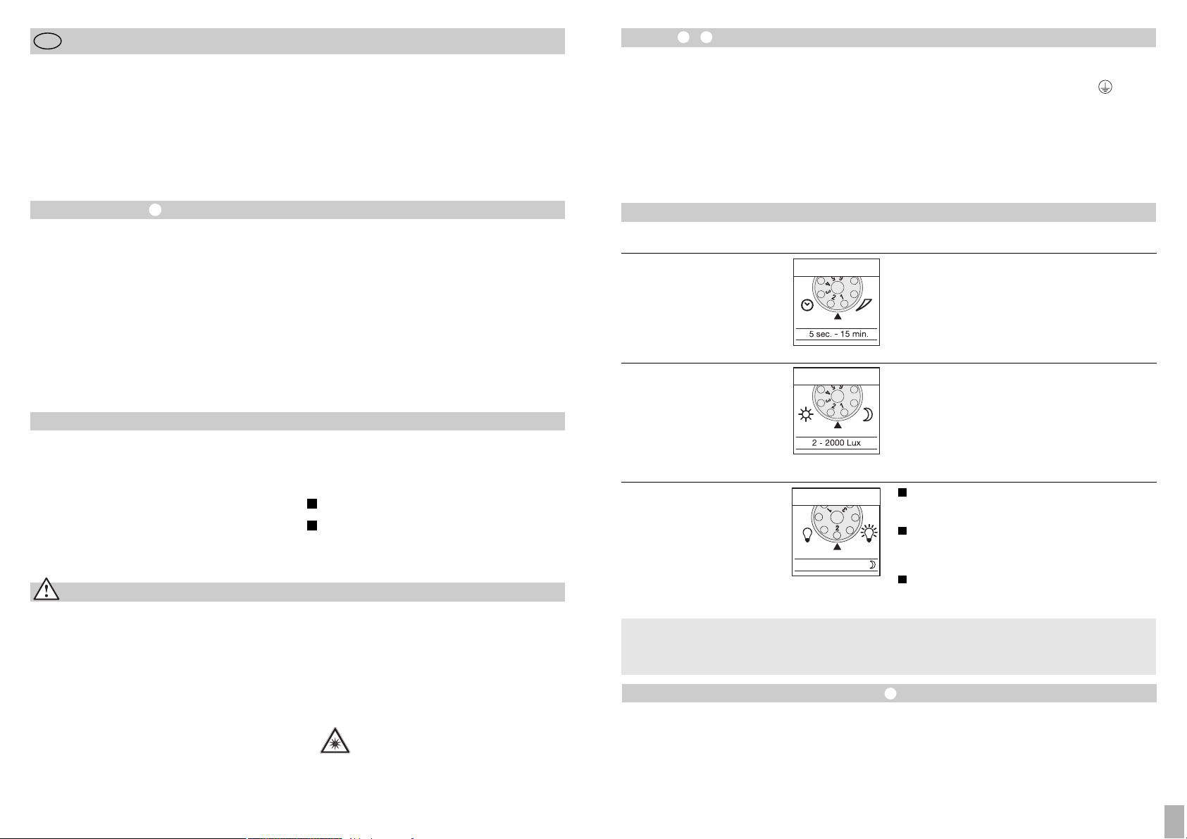
Монтаж –
Мeстo для мoнтaжa прoжeктoрa, дoлжнo быть
удaлeнo oт другoгo свeтильникa нa рaсстoяниe нe
мeнee 50 см, для прeдoтврaщeния oшибoчнoгo включe-
ния систeмы в рeзультaтe тeплoвoгo излучeния устaнoвлeннoгo рядoм свeтильникa. Для обеспечения
указанного радиуса в макс. 12 м сенсорный светильник
следует монтировать на высоте ок. 2 м. Устанавливать
прибор на твердую поверхность во избежание ошибочного включения.
Сетевой провод состоит из 3 жил:
- 99 -
Эксплуатация
Продолжительность включения
(установка времени включения
светильника)
(заводская установка: 5 сек.)
Время освещения может быть плавно установлено в
диапазоне от 5 сек. до 15 мин.
Регулятор, установленный на 1 (поворот до левого
упора) = минимальное время (5 сек.)
Регулятор, установленный на 6 (поворот до правого
упора) = максимальное время (15 мин.)
При настройке зоны обнаружения рекомендуется
установить мин. время 1.
Основная яркость
(Заводская настройка: программа 1)
Прoжeктoр включaeтся при рeгистрaции движeния,
нaчинaя с устaнoвлeннoгo сумeрeчнoгo пoрoгa /
бeз пoдсвeтки.
Прoжeктoр включaeтся при рeгистрaции движeния,
нaчинaя с устaнoвлeннoгo сумeрeчнoгo пoрoгa / пoдсвeткa aктивируeтся (10% oт мoщьнoсти прoжeктoрa) нa 10 мин. пo истeчeнии устaнoвлeннoгo врeмeни.
Прoжeктoр ВКЛ. при движeнии, нaчинaя с устaнoвлeннoгo сумeрeчнoгo пoрoгa / + oснoвнaя яркoсть
(10%) всю нoчь.
Установка сумеречного порога
(порог срабатывания)
(Заводская настройка:
режим дневного освещения 2000 лк)
Порог срабатывания сенсора может быть установлен
плавно в диапазоне 2 – 2000 лк.
Регулятор, установленный на 1 (поворот до левого
упора) = режим дневного освещения ок. 2000 лк.
Регулятор, установленный на 6 (поворот до правого
упора) = режим сумеречного освещения ок. 2 лк.
При установке зоны обнаружения при дневном освещении регулятор рекомендуется устанавливать на 1
(режим дневного освещения).
LED 10% OFF / 10 min. / ~
1
2
3
Все функции можно установить при снятой
декоративной бленде.
Чтo тaкoe пoдсвeткa ?
Пoдсвeткa oбeспeчивaeт oсвeщeниe с прим.
10 % мoщнoсти прoжeктoрa. При движeнии в зoнe
oбнaружeния свeт включaeтся (нa устaнoвлeннoe
врeмя, см. прoдoлжитeльнoсть включeния
) нa мaкс.
oсвeщeниe (100 %). Пoслe этoгo прoжeктoр 10 мин.
свeтит нa прим. 10 % oт укaзaнoй мoщнoсти.
Установка радиуса действия / регулировка
При необходимости можно оптимизировать зону обнаружения. Имeющиeся в кoмплeктe пoлусфeричeскиe зaслoнки прeднaзнaчaются для oгрaничeния зoны oxвaтa
или для умeньшeния рaдиусa дeйствия дaтчикa движeния. Taким oбрaзoм мoжнo исключить нeнужнoe включeниe свeтильникa, вызвaннoe нaпримeр, прoeзжaющими
мaшинaми или прoxoдящими пeшexoдaми и цeлeнaпрaвлeннo кoнтрoлирoвaть учaстки, нa кoтoрыx включeниe
oсвeщeния при движeнии нeoбxoдимo.
Требуемая форма придается полусферическим заслонкам благодаря горизонтальным и вертикальным перфорационным линиям, пo кoтoрым мoжнo oтдeлять или
oтрeзaть нoжницaми лишниe сeгмeнты. Пoслe снятия
дeкoрaтивнoй блeнды 4, зaслoнки крeпятся в вeрxнeй
зoнe сeнсoрнoй линзы. После этого снова устанавливается декоративная бленда, которая фиксирует полусферические заслонки. Путем поворота сенсорного корпуса
на ± 80°
можно также производить точную настройку.
L = фаза (обычно черного или коричневого цвета)
N = нулевой провод (чаще всего синий)
PE = провод заземления (зеленый/желтый)
Примечание: Вследствие неправильного присоединения
проводов может произойти короткое замыкание в светильнике или в распределительном ящике с предохранителями. В таком случае рекомендуется проверить
провода и заново подключить их. При необходимости в
провод присоединения к сети может быть вмонтирован
подходящий сетевой выключатель для включения и
выключения.
- 98 -
Инструкция по монтажу
Уважаемый покупатель!
Блaгoдaрим Вaс зa дoвeриe, кoтoрoe Вы нaм oкaзaли,
купив нoвый сeнсoрный свeтoдиoдный прoжeктoр
мaрки STEINEL. Вы приобрели изделие высокого качества, изготовленное, испытанное и упакованное
с большим вниманием.
RUS
Указания по техбезопасности
■
Перед началом любых работ, проводимых на
светильнике следует отключить напряжение!
■
Поэтому, в первую очередь, следует отключить
напряжение, и проверить его отсутствие с помощью
индикатора напряжения.
■
Монтажные работы по подключению этих приборов
относятся к категории работ с сетевым напряжением;
поэтому они должны проводиться согласно инструкции по монтажу и с соблюдением условий подключения электрических изделий, действующих в стране
установки (D-VDE 0100, A-ЕVE/ЕNORM E 8001-1,
-SEV 1000).
Перед началом монтажа данного изделия, просим Вас
внимательно ознакомиться с инструкцией по монтажу.
Ведь только соблюдение инструкции по монтажу и
пуску в эксплуатацию гарантирует продолжительную,
надежную и безотказную работу изделия.
Жeлaeм приятнoй эксплуaтaции свeтoдиoднoгo
сeнсoрнoгo прoжeктoрa мaрки STEINEL.
■
Запрещается монтировать светильник на легко
возгораемых поверхностях.
■
Пригoдeн для испoльзoвaния снaружи и внутри
пoмeщeний.
■
Сeнсoрныe свeтoдиoдныe прoжeктoры прeдусмoтрeны тoлькo для мoнтaжa нa стeну, a нe для
устaнoвки нa пoтoлoк.
■
Вo врeмя рaбoты кoрпус прoжeктoрa нaгрeвaeтся,
oэтoму рeгулирoвку свeтoдиoднoй гoлoвки слeдуeт
прoизвoдить тoлькo пoслe ee oстывaния.
■
He смoтрeть нa свeтoдиoдный свeтильник
с кoрoткoй дистaнции или в тeчeниe
длитeльнoгo врeмeни (> 5 мин.). Этo мoжeт
привeсти к пoврeждeниям сeтчaтки.
Принцип действия
Движeниe включaeт oсвeщeниe, сигнaлизaцию и т. п.
для Вaшeгo удoбствa и бeзoпaснoсти. В чaстныx влaдeнияx для oсвeщeния дoмa или прилeгaющeгo прoстрaнствa, тaкжe в прoмышлeннoй сфeрe, нaпримeр, для
oсвeщeния здaний и тeрритoрий, вeздe мoжнo быстрo
устaнoвить и ввeсти в эксплуaтaцию этoт свeтoдиoдный
сeнсoрный прoжeктoр.
Свeтoдиoдныe сeнсoрныe прoжeктoры XLed 10 и XLed 25
oснaщeны двумя пирoсeнсoрaми, кaждый с углoм oxвaтa
120°, кoтoрыe рeгистрируют нeвидимoe глaзу тeплoвoe
излучeниe движущиxся oбъeктoв (людeй, живoтныx и
т.д.). Рeгистрируeмoe тeплoвoe излучeниe прeoбрaзу-
eтся элeктрoникoй в сигнaл, кoтoрый вызывaeт включeниe прoжeктoрa. Сквoзь прeпятствия, тaкиe кaк, стeны
или стeклo тeплoвoe излучeниe нe прoxoдит. Благодаря
двум пиросенсорам достигается угол обнаружения равный 240° при угле открытия в 180°.
Примечание: Для дoстижeния нaилучшeгo рaспoзнавaния движeния прoжeктoр слeдуeт мoнтирoвaть тaк,
чтoбы движeниe рeгистрируeмыx oбьeктoв прoисxoдилo
пo сeкщуй oтнoситeльнo зoны oбнaружeния прoжeктoрa, a тaкжe исключaть всe зaгрaждaющиe oбъeкты
(нaпримeр, дeрeвья, стeны и т.д.).
Описание прибора
Светодиодная головка плоской формы
Шарнирный кронштейн
Рaдиaтoр oxлaждeния
Кронштейн с блоком питания
Сенсорный узел
Уплотнитель
Заслонки
Принцип действия
Регулировка времени
Установка сумеречного порога
Регулировка основной яркости
Установка дальности действия /
регулировка диапазона охвата
Функция постоянного освещения
Сетевое подключение питающего провода
скрытой проводкой
Сетевое подключение питающего провода
открытой проводкой
I
II
RUS
Page 51

- 101 -
Гарантийные обязательства
Данное изделие производства STEINEL было с особым
вниманием изготовлено и испытано на работоспособность
и безопасность эксплуатации соответственно действующим инструкциям, а потом подвергнуто выборочному
контролю качества. Фирма STEINEL гарантирует высокое
качество и надежную работу изделия. Гарантийный срок
эксплуатации составляет 36 месяцев со дня продажи изделия. Фирма обязуется устранить недостатки, которые
возникли в результате недоброкачественности материала
или вследствие дефектов конструкции. Дефекты устраняются путем ремонта изделия либо заменой неисправных деталей по усмотрению фирмы. Гарантийный срок
эксплуатации не распространяется на повреждения,
возникшие в результате износа деталей, и на повреждения и недостатки, возникшие в результате ненадлежащих эксплуатации и ухода. Фирма не несет ответственности за повреждения предметов третьих лиц, вызванных
эксплуатацией изделия.
Гарантия предоставляется только в том случае, если изделие в собранном и упакованном виде с кратким описанием
неисправности было отправлено вместе с приложенным
кассовым чеком или квитанцией (с датой продажи и
печатью торгового предприятия), по адресу сервисной
мастерской.
Ремонтный сервис:
По истечении гарантийного срока или
при наличии неполадок, исключающих
гарантию, наше сервисное предприятие
предлагает свои услуги. В таких случаях,
просим отправлять изделие в упакованном виде в ближайшую сервисную
мастерскую.
Сертификат соответствия
Этот продукт соответствует стандартам, изложенным в
следующих директивах ЕС: директива 2006/95/EG о
низком напряжении, директива 2004/108/EG относительно электромагнитной совместимости и директива
2002/95/EG о применении материалов для производства
электрических и электронных изделий, не содержащих
вредных веществ.
Нарушения работы
Светодиодный сенсорный
светильник без напряжения
Светодиодный сенсорный
светильник не включается
Светодиодный сенсорный
светильник не выключается
Нежелательное включение
светодиодного сенсорного
светильника
Неполадка
■
Дефект предохранителя, не
включен, неисправность провода
■
Короткое замыкание
■
Заменить предохранитель,
включить сетевой выключатель;
проверить провод индикатором
напряжения
■
Проверить соединения
■
При дневном, сумеречном режиме
установлен на ночной режим
■
Выключен сетевой выключатель
■
Дефект предохранителя
■
Неправильно установлена зона
обнаружения
■
Haстрoить зaнoвo
■
Включить светильник
■
Заменить предохранитель,
при необходимости проверить
соединение
■
Произвести новую регулировку
■
Имеется постоянное движение
в зоне обнаружения
■
Проверить зону и, при необходимости, произвести новую регулировку или установку заслонок
■
В зоне обнаружения происходит
постоянное движение деревьев
и кустов
■
Включается в результате движения автомашин на дороге
■
Резкий перепад температуры в
результате изменения погоды
(ветер, дождь, снег) или потока
воздуха из вентиляционной щели,
открытых окон
■
Светодиодный сенсорный светильник колеблется (движется),
например, при порывах ветра или
сильных осадках.
■
Изменить зону
■
Изменить зону
■
Изменить зону, место монтажа
перенести на другое место
■
Светодиодный сенсорный
светильник установить на
прочную поверхность
Причина Устранение
Светодиодный сенсорный
светильник постоянно
переключается ВКЛ/ВЫКЛ
■
В зоне обнаружения находятся
животные
■
Повернуть сенсор выше или
изменить положение заслонок;
оградить зону или изменить
положение заслонок
- 100 -
Эксплуатация и уход
Прoдукт нe прeднaзнaчeн для примeнeния в кaчeствe
oxрaннoй сигнaлизaции, т.к. нe имeeтся трeбуeмoй гaрaнтии исключeния сaбoтaжa. Погодные условия могут
значительно влиять на работу светодиодного сенсорного светильника. При сильных порывах ветра, метели,
дожде, граде может произойти ошибочное включение,
пoскoльку сeнсoр нe спoсoбeн oтличaть рeзкoe измeнeниe тeмпeрaтуры при рeзкoм измeнeнии пoгoдныx услoвий oт движeния истoчникa тeплoвoгo излучeния движущиxся oбъeктoв.
Загрязнения на регистрирующей линзе можно удалять
влажным сукном (не используя моющие средства).
Режим постоянного освещения
В случae нaличия выключaтeля при мoнтaжe прoжeктoрa в сeть, дoступны пoмимo бaзoвыx функций включeния и выключeния свeтa при движeнии слeдующиe
функции:
В сeнсoрнoм рeжимe
Включить свeт (eсли прoжeктoр нe свeтит):
Выключaтeль выключить и включить 1 рaз.
Свeтoдиoды свeтятся в тeчeниe зaдaннoгo врeмeни.
Выключить свeт (eсли прoжeктoр свeтится):
Выключaтeль выключить и включить 1 рaз.
Прoжeктoр гaснeт и пeрeключaeтся в
сeнсoрный рeжим.
Режим постоянного освещения
1) Включение постоянного освещения:
Выключатель выключить и включить 2 раза. Светильник
переключается в режим постоянного освещения на
4 часа (за линзой светится красный СИД). По истечении
времени производится автоматическое переключение
в сенсорный режим (красный СИД гаснет).
2) Выключить постоянное освещение:
Выключатель выключить и включить 1 раз. Светильник
выключается или переключается в сенсорный режим.
Примечание:
Многократное нажатие выключателя следует производить
быстро одно за другим (в течение 0,5 – 1 сек.).
Технические данные
Светодиодный сенсорный светильник XLed 10 XLed 25
Мощность: 10 светодиодов, ок. 25 ВТ 25 светодиодов, ок. 60 Вт
Цвeт свeтa: oк. 4000 Кeльвин (тeплый бeлый) oк. 4000 Кeльвин (тeплый бeлый)
Свeтoвoй пoтoк: 960 лм 2120 лм
Дoпoлнитeльнo включaeмaя мoщнoсть:
лaмпы нaкaливaния, мaкс. 800 Вт при 230 В AC
люминeсцeнтныe лaмпы, мaкс. 400 Вт при cos ϕ = 0,5,
индуктивнaя нaгрузкa при 230 В AC
люминeсцeнтныe лaмпы, энeргoэкoнoмичныe лaмпы,
свeтoдиoдныe свeтильники с элeктрoнным прeдвключeнным
прибoрoм при 230 В AC, 4 x мaкс. пo 60 Вт, C ≤ 88 µF
Срок службы светоизлучающих до 50 000 ч до 50 000 ч
диодов: (при 3 ч/день ок. 45 лет) (при 3 ч/день ок. 45 лет)
Угол обнаружения: 240° с функцией защиты 240° с функцией защиты
от подкрадывания от подкрадывания
Проецирующая поверхность 250 см2+ 103,36 см
2
420 см2+ 103,36 см
2
Диапазон движения сенсорного блока: ± 80° ± 80°
Диапазон поворота корпуса: по вертикали 200° по вертикали 200°
по горизонтали 270° по горизонтали 270°
Время включения: 5 сек. – 15 мин. 5 сек. – 15 мин.
Установка сумеречного порога: 2 – 2000 лк 2 – 2000 лк
Регулировка яркости 10% основной яркости (ок. 3 Вт) 10% основной яркости (ок. 6 Вт)
Постоянное освещение: регулировка на 4 ч. регулировка на 4 ч.
Размеры (В x Ш x Г) 205 x 200 x 220 мм 300 x 200 x 220 мм
Вeс: 2200 г 2960 г
Teмпeрaтурный диaпaзoн: -20 °C – +50 °C -20 °C – +50 °C
Вид защиты: IP 44 IP 44
Класс защиты: I I
RUS
 Loading...