

DE
STEINEL Vertrieb GmbH
Dieselstraße 80-84
3
3442 Herzebrock-Clarholz
Tel: +49/5245/448-188
www.steinel.de
A
T
Steinel Austria GmbH
Hirschstettner Strasse 19/A/2/2
A
-1220 Wien
Tel.: +43/1/2023470
info@steinel.at
CH
PUAG AG
Oberebenestrasse 51
CH-5620 Bremgarten
Tel.: +41/56/6488888
info@puag.ch
GB
STEINEL U.K. LTD.
25, Manasty Road · Axis Park
Orton Southgate
GB-Peterborough Cambs PE2 6UP
Tel.: +44/1733/366-700
steinel@steinel.co.uk
IE
Socket Tool Company Ltd
U
nit 714 Northwest Business Park
Kilshane Drive · Ballycoolin · Dublin 15
Tel.: 00353 1 8809120
info@sockettool.ie
FR
STEINEL FRANCE SAS
ACTICENTRE - CRT 2
Rue des Famards - Bât. M - Lot 3
F-59818 Lesquin Cedex
Tél.: +33/3/20 30 34 00
info@steinelfrance.com
NL
Van Spijk B.V.
Postbus 2
5688 HP OIRSCHOT
De Scheper 402
5688 HP OIRSCHOT
Tel. +31 499 571810
info@vanspijk.nl
www.vanspijk.nl
BE
VSA Belgium
Hagelberg 29
B-2440 Geel
Tel.: +32/14/256050
info@vsabelgium.be
www.vsabelgium.be
LU
Minusines S.A.
8, rue de Hogenberg
L-1022 Luxembourg
Tél. : (00 352) 49 58 58 1
www.minusines.lu
ES
SAET-94 S.L.
C/ Trepadella, n° 10
Pol. Ind. Castellbisbal Sud
E-08755 Castellbisbal (Barcelona)
Tel.: +34/93/772 28 49
saet94@saet94.com
IT
STEINEL Italia S.r.l.
Largo Donegani 2
I-20121 Milano
Tel.: +39/02/96457231
info@steinel.it
www.steinel.it
PT
F.Fonseca S.A.
Rua Joao Francisco do Casal, 87/89
E
sgueira, 3800-266 Aveiro - Portugal
Tel. +351 234 303 900
ffonseca@ffonseca.com
www.ffonseca.com
S
E
KARL H STRÖM AB
Verktygsvägen 4
SE-553 02 Jönköping
T
el.: +46 36 550 33 00
info@khs.se
www.khs.se
DK
Roliba A/S
Hvidkærvej 52
D
K-5250 Odense SV
Tel.: +45 6593 0357
www.roliba.dk
FI
Oy Hedtec Ab
Lauttasaarentie 50
FI-00200 Helsinki
Puh.: +358/207 638 000
v
alaistus@hedtec.fi
www.hedtec.fi/valaistus
NO
Vilan AS
Olaf Helsetsvei 8
N-0694 Oslo
Tel.: +47/22725000
post@vilan.no
www.vilan.no
GR
PANOS Lingonis + Sons O. E.
Aristofanous 8 Str.
GR-10554 Athens
Tel.: +30/210/3212021
lygonis@otenet.gr
TR
SAOS Teknoloji Elektrik Sanayi ve
Ticaret Limited Şirketi
Halil Rıfat Paşa mahallesi
Yüzerhavuz Sokak
PERPA Ticaret Merkezi A Blok
Kat 5 No.313
Şişli / İSTANBUL
Tel.: +90 212 220 09 20
iletisim@saosteknoloji.com.tr
www.saosteknoloji.com.tr
CZ
ELNAS s.r.o.
Oblekovice 394
CZ-67181 Znojmo
Tel.: +420/515/220126
info@elnas.cz · www.elnas.cz
PL
„LŁ“ Spółka z ograniczoną
odpowiedzialnością sp.k.
Byków, ul. Wrocławska 43
PL-55-095 Mirków
Tel.: +48 71 3980818
handlowy@langelukaszuk.pl
www.langelukaszuk.pl
HU
DINOCOOP Kft
Radvány u. 24
H-1118 Budapest
Tel.: +36/1/3193064
dinocoop@dinocoop.hu
LT
KVARCAS
Neries krantine 32
L
T-48463, Kaunas
Tel.: +370/37/408030
info@kvarcas.lt
E
E
Fortronic AS
Tööstuse tee 10,
EST-61715, Tõrvandi,
Ü
lenurme vald, Tartumaa
Tel.: +372/7/475208
info@fortronic.ee
w
ww.fortronic.ee
SI
ELEKTRO – PROJEKT PLUS D.O.O.
Suha pri Predosljah 12
SLO-4000 Kranj
PE GRENC 2
4220 Škofja Loka
Tel.: 00386-4-2521645
GSM: 00386-40-856555
info@elektroprojektplus.si
w
ww.priporocam.si
SK
NECO SK, A.S.
R
užová ul. 111
SK-01901 Ilava
Tel.: +421/42/4 45 67 10
neco@neco.sk
www.neco.sk
RO
Steinel Distribution SRL
505400 Rasnov, jud. Brasov
Str. Campului, nr.1
FSR Hala Scularie Birourile 4-7
Tel.: +40(0)268 53 00 00
www.steinel.ro
HR
Daljinsko upravljanje d.o.o.
Bedricha Smetane 10
HR-10000 Zagreb
t/ 00385 1 388 66 77
daljinsko-upravljanje@inet.hr
www.daljinsko-upravljanje.hr
LV
Ambergs SIA
Brīvības gatve 195-16
LV-1039 Rīga
Tel.: 00371 67550740
www.ambergs.lv
BG
ТАШЕВ-ГАЛВИНГ ООД
Бул. Климент Охридски № 68
1756 София, България
Тел.: +359 2 700 45 45 4
info@tashev-galving.com
www.tashev-galving.com
RU
Best - Snab
ул.1812 года, дом 12
121127 Москва · Россия
Tel: +7 (495) 280-35-53
info@steinel.su
www.steinel.su
CN
STEINEL China
Representative Office
Shanghai Rm. 25 A,
Huadu Mansion No. 838
Zhangyang Road Shanghai 200122
Tel: +86 21 5820 4486
james.chai@steinel.cn
info@steinel.cn
www.steinel.cn
DGBFNLIE
P
SDK
FI
NGRTRHCZSKPLROMSLOHRESTLT
Information
LV
XLED 10
110030975 10/2018_L Technische Änderungen vorbehalten. / Subject to technical modification without notice.
XLED 25
RUSBG
中

XLed 10 / XLed 25
XLed 10 / XLed 25
XLed 25XLed 10
2.
3.
1.
4.
II
1.
- 2- - 3-
2.
I
3.
4.
XLed 10 / XLed 25
XLed 10 / XLed 25
- 4- - 5-
D
Montageanleitung
Sehr geehrter Kunde,
ielen Dank für das Vertrauen, das Sie uns beim Kauf
v
hres neuen STEINEL-Sensor-LED-Strahlers ent-
I
egengebracht haben. Sie haben sich für ein hoch-
g
wertiges Qualitätsprodukt entschieden, das mit größter Sorgfalt produziert, getestet und verpackt wurde.
Bitte machen Sie sich vor der Installation mit dieser
Das Prinzip
Bewegung schaltet Licht, Alarm und vieles mehr. Für
Ihren Komfort, zu Ihrer Sicherheit. Sei es im privaten
Bereich zur Haus- und Grundstücksbeleuchtung oder
im gewerblichen Bereich z.B. zur Beleuchtung des
Firmengeländes, dieser Sensor-LED-Strahler ist überall schnell montiert und betriebsbereit.
Die Sensor-LED-Strahler XLed 10 und XLed 25 sind
mit zwei 120°-Pyro-Sensoren ausgestattet, die die
unsichtbare Wärmestrahlung von sich bewegenden
Körpern (Menschen, Tieren, etc.) erfassen. Diese so
erfaßte Wärmestrahlung wird elektronisch umgesetzt
Gerätebeschreibung
LED-Kopf im Flat-Design
Gelenkarm
Kühlrippen
Wandhalter mit Netzteil
Sensoreinheit
Dichtstopfen
Abdeckschalen
Sicherheitshinweise
n Vor allen Arbeiten am Gerät die Spannungs zufuhr
unterbrechen!
n Bei der Montage muss die anzuschließende
elektrische Leitung spannungsfrei sein. Daher als
Erstes Strom abschalten und Spannungsfreiheit
mit einem Spannungsprüfer überprüfen.
n Bei der Installation dieser Geräte handelt es sich
um eine Arbeit an der Netz spannung; sie muss
da her fachgerecht nach den länderspezifischen
In stal lations vorschriften und Anschluß bedingungen
durchgeführt werden (D-VDE 0100,
A
-ÖVE/ÖNORM E 8001-1, -SEV 1000)
Montageanleitung vertraut. Denn nur eine sachgerechte Installation und Inbetriebnahme gewährleistet
inen langen, zuverlässigen und störungsfreien
e
etrieb.
B
Wir wünschen Ihnen viel Freude an Ihrem neuen
STEINEL-Sensor-LED-Strahler.
Installation –
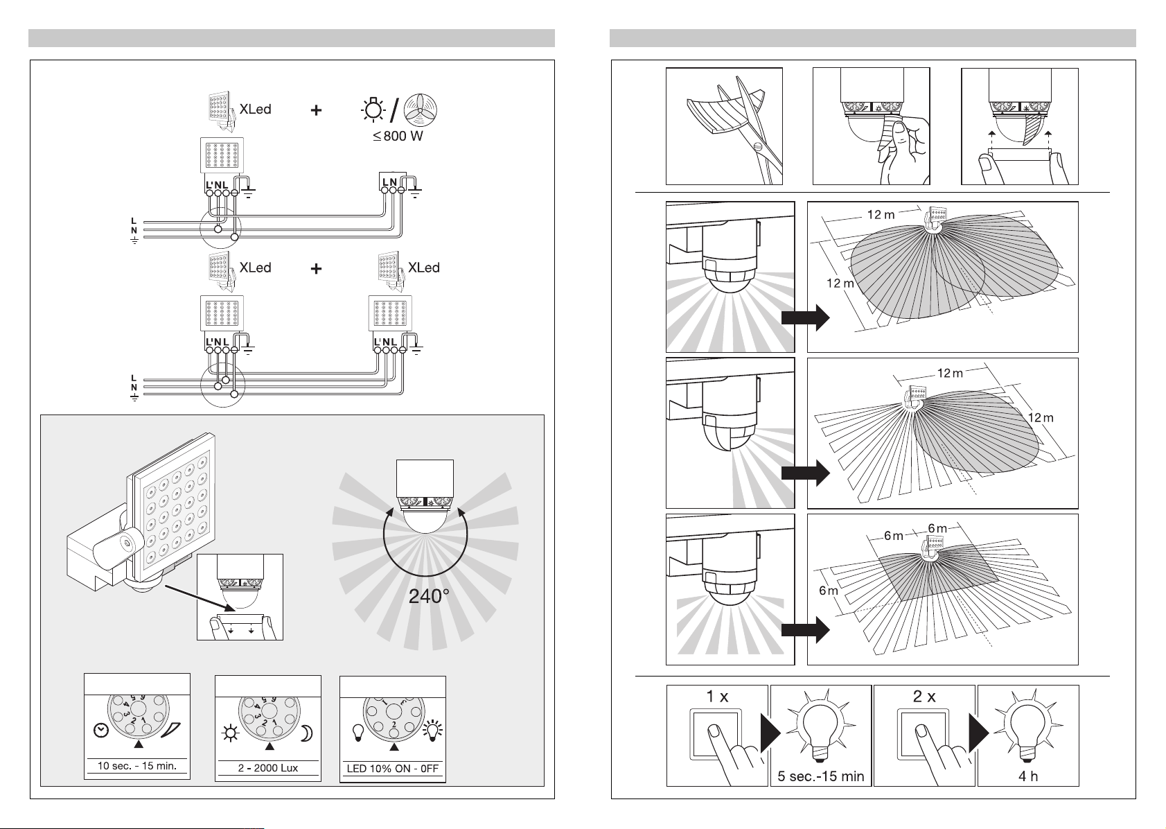
Der Montageort sollte mindestens 50 cm von einer
anderen Leuchte entfernt sein, da Wärmestrahlung
ur Auslösung des Systems führen kann. Um die
z
ngegebene Reichweite von max. 12 m zu erzielen,
a
ollte die Montagehöhe ca. 2 m betragen. Montieren
s
Sie das Gerät auf einen festen Untergrund, um Fehlschaltungen zu vermeiden.
Die Netzzuleitung besteht aus einem 3-adrigen Kabel:
Phase (meistens schwarz oder braun)
L =
Neutralleiter (meistens blau)
N =
E = Schutzleiter (grün/gelb)
P
Funktionen
und schaltet so den Strahler. Durch Hindernisse, wie
z.B. Mauern oder Glasscheiben, wird keine Wärmestrahlung erkannt. Mit Hilfe der zwei Pyro-Sensoren
wird ein Erfassungswinkel von 240° mit einem Öffnungswinkel von 180° erreicht.
Wichtig: Die sicherste Bewe gungserfassung haben
Sie, wenn Sie das Gerät seitlich zur Gehrichtung
montieren und keine Hindernisse (wie z.B. Bäu me,
Mauern etc.) die Sicht des Sensors behindern.
Das Prinzip
Zeiteinstellung
Dämmerungseinstellung
Einstellung Grundhelligkeit
Reichweiteneinstellung/
Justierung des Erfassungsbereichs
Dauerlichtfuktion
Netzanschluss Zuleitung Unterputz
I
Netzanschluss Zuleitung Aufputz
II
Montieren Sie das Gerät nicht auf gewöhnlich leicht
n
entflammbaren Oberflächen.
n Geeignet für Außen- und für Innenräume.
n Der Sensor-LED-Strahler ist nur für die Wand-
montage und nicht für die Decken montage
vorgesehen.
n Das Strahlergehäuse erwärmt sich während des
Betriebes. Die Ausrichtung des LED-Kopfes nur
durchführen, wenn dieser abgekühlt ist.
n Die Leuchte ist so zu positionieren, dass
- 6- - 7-
längeres Starren in die Leuchte in einem
geringeren Abstand als 1,8 m nicht zu
erwarten ist.
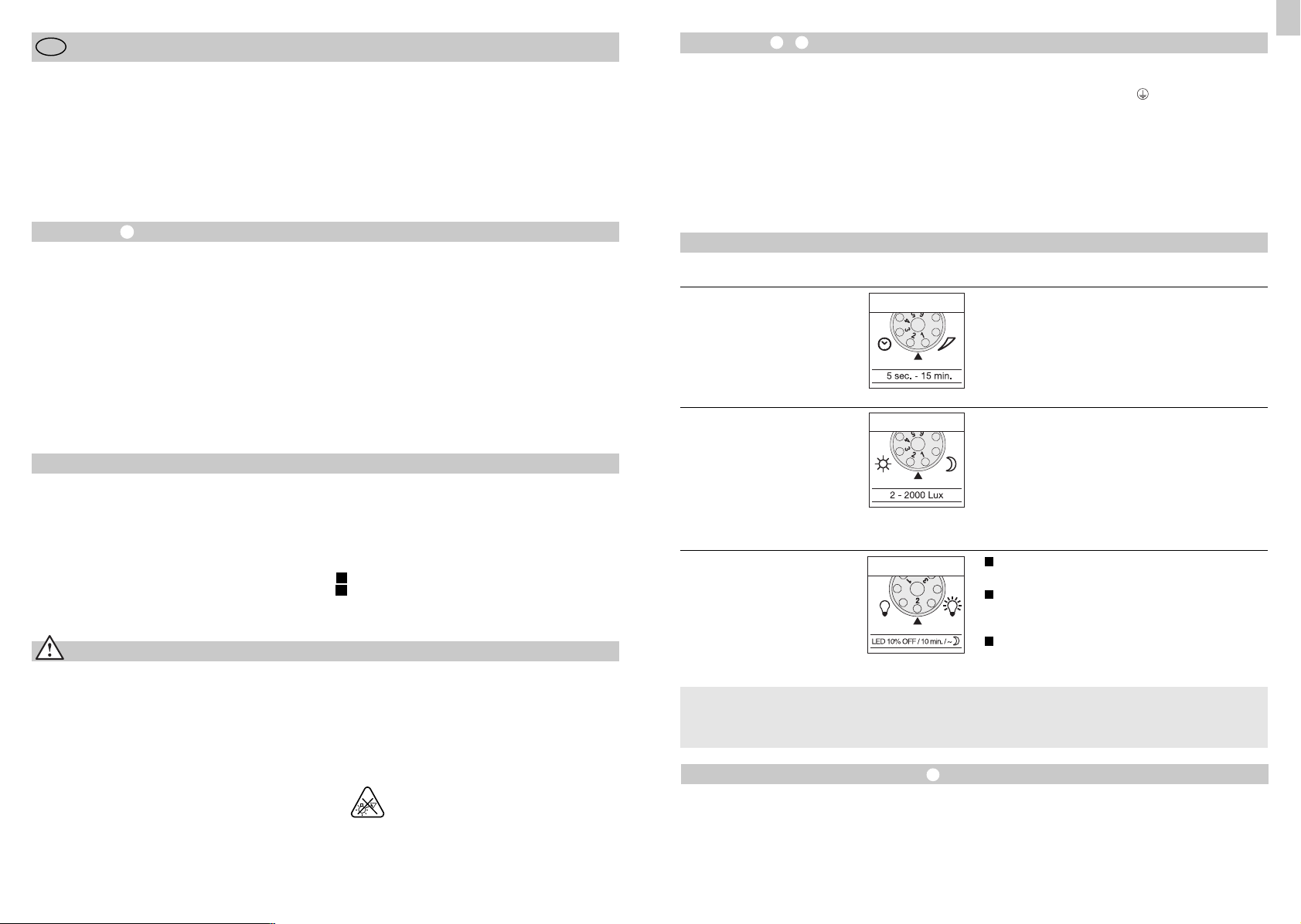
Alle Funktionen lassen sich bei abgezogener
Ringblende einstellen.
Ausschaltverzögerung
(Zeiteinstellung)
(Werkseinstellung: 5 Sek.)
Dämmerungseinstellung
(Ansprechschwelle)
(Werkseinstellung:
Tageslichtbetrieb 2000 Lux)
Grundhelligkeit
(Werkseinstellung: Programm 1)
Was ist Grundhelligkeit ?
Grundhelligkeit ermöglicht eine Beleuchtung mit ca.
10 % Lichtleistung. Erst bei Bewegung im Erfassungsbereich wird das Licht (für die eingestellte Zeit,
Reichweiteneinstellung/Justierung
Je nach Bedarf kann der Erfassungsbereich optimiert
werden. Die beiliegenden Abdeckblenden dienen
dazu, beliebig viele Linsensegmente abzudecken,
bzw. die Reichweite individuell zu verkürzen. Somit
werden Fehlschaltungen durch z. B. Autos, Passanten etc. ausgeschlossen oder Gefahrenstellen gezielt
überwacht. Die Abdeckblenden können entlang der
vorgenuteten Einteilungen in der Senkrechten und
Wichtig: Ein Vertauschen der Anschlüsse führt im
e rät oder Ihrem Siche rungs ka sten später zum Kurz -
G
chluss. In diesem Fall müssen die einzelnen Kabel
s
dentifiziert und neu montiert werden. In die Netzzu-
i
eitung kann ein geeigneter Netz schalter zum EIN-
l
und AUS-Schalten montiert sein.
Hinweis: Die Lichtquelle dieser Leuchte darf nur
vom Hersteller oder einem von ihm beauftragten
ervicetechniker oder einer vergleichbar qualifizierten
S
erson ersetzt werden.
P
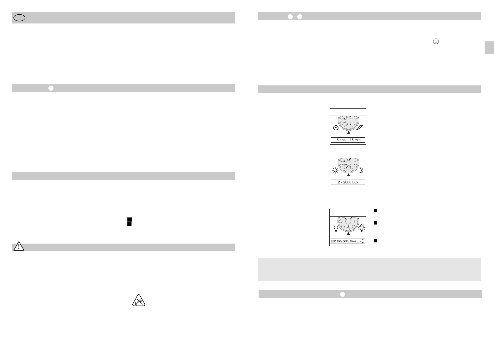
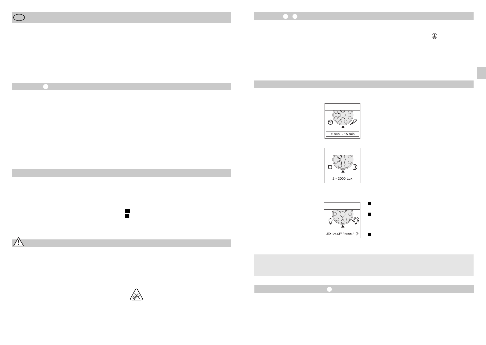
Stufenlos einstellbare Leuchtdauer von 5 sek. –15 min.
Einstellreger auf 1 (Linksanschlag) gestellt =
kürzeste Zeit (5 Sek.)
Einstellreger auf 6 (Rechtsanschlag) gestellt =
längste Zeit (15 min.)
Bei Einstellung des Erfassungsbereiches wird
empfohlen die kürzeste Zeit 1 zu wählen.
Stufenlos einstellbare Ansprechschwelle des Sensors
von 2 – 2000 Lux.
Einstellregler auf 1 (Linksanschlag) gestellt =
Tageslichtbetrieb ca. 2000 Lux.
Einstellregler auf 6 (Rechtsanschlag) gestellt =
Dämmerungsbetrieb ca. 2 Lux.
Zur Einstellung des Erfassungsbereiches bei Tageslicht
ist der Einstellregler auf 1 (Tageslichtbetrieb) zu
stellen.
1
Strahler AN bei Bewegung ab eingestelltem
Dämmerungswert / keine Grundhelligkeit.
2
Strahler AN bei Bewegung ab eingestelltem
Dämmerungswert / + Grundhelligkeit (10%)
für 10 min. nach Ablauf der eingestellten Zeit.
3
Strahler AN bei Bewegung ab eingestelltem
Dämmerungswert / + Grundhelligkeit (10%)
die ganze Nacht
s. Ausschaltverzögerung ) auf maximale Lichtleistung (100 %) geschaltet. Danach schaltet die
Leuchte für 10 Min. auf Grundhelligkeit (ca. 10 %).
Waagerechten getrennt oder mit einer Schere
geschnitten werden. Nach Abziehen der Ringblende
sind diese im oberen Bereich der Sensorlinse einzuhängen. Die Ringblende ist danach wieder aufzustecken, wodurch die Abdeckblenden fest verankert
werden.
Durch Drehen des Sensorgehäuses um ± 80° ist
darüber hinaus eine Feinabstimmung möglich.
D
Dauerlichtfunktion
ird ein Netzschalter in die Netzzuleitung montiert,
W
ind neben dem einfachen Ein- und Ausschalten
s
olgende Funktionen möglich:
f
Sensorbetrieb
1) Licht einschalten (wenn Strahler AUS):
chalter 1 x AUS und AN.
S
EDs bleiben für die eingestellte Zeit an.
L
) Licht ausschalten (wenn Strahler AN):
2
chalter 1 x AUS und AN.
S
Strahler geht aus bzw. in den Sensorbetrieb über.
auerlichtbetrieb
D
) Dauerlicht einschalten:
1
chalter 2 x AUS und AN. Der Strahler wird für
S
Stunden auf Dauerlicht gestellt (rote LED leuchtet
4
hinter der Linse). Anschließend geht sie automatisch
wieder in den Sensorbetrieb über (rote LED aus).
2) Dauerlicht ausschalten:
chalter 1 x AUS und AN. Strahler geht aus bzw. in
S
en Sensorbetrieb über.
d
Wichtig:
as mehrmalige Betätigen des Schalters sollte schnell
D
intereinander erfolgen (im Bereich 0,5 – 1 Sek.).
h
Betrieb und Pflege
Für spezielle Einbruchalarmanlagen ist das Gerät
nicht geeignet, da die hierfür vorgeschriebene Sabotagesicherheit fehlt. Witterungseinflüsse können die
Funktion der Sensor-LED-Strahler beeinflussen. Bei
starken Windböen, Schnee, Regen, Hagel kann es
zu einer Fehlschaltung kommen, da die plötzlichen
Temperaturschwankungen nicht von Wärmequellen
unterschieden werden können.
Die Erfassungslinse kann bei Verschmutzung mit
einem feuchten Tuch (ohne Reinigungsmittel)
gesäubert werden.
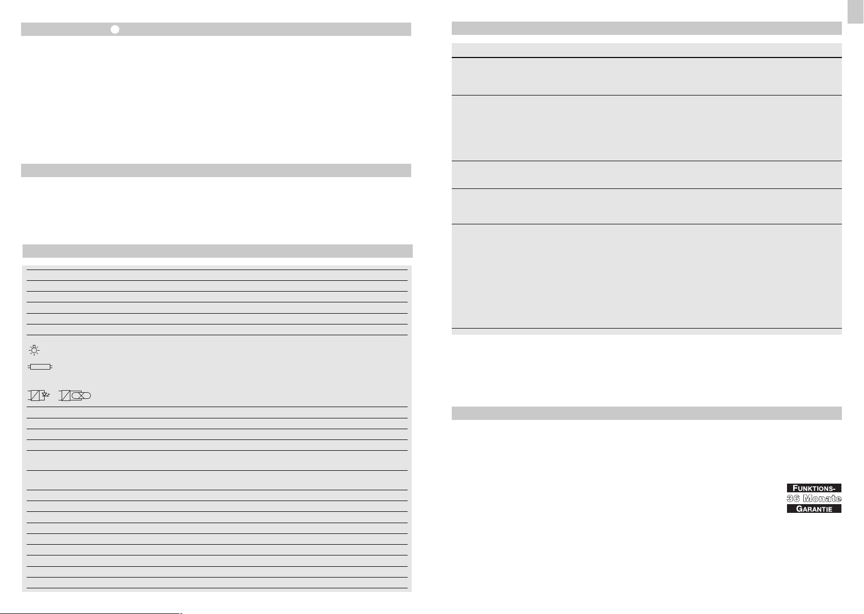
Technische Daten
Sensor-LED-Strahler XLed 10 XLed 25
Netzanschluss: 230-240 V, 50 Hz 230-240 V, 50 Hz
Leistung: 10 LEDs, ca. 30 W 25 LEDs, ca. 62 W
Lichtfarbe: ca. 4100 Kelvin (warmweiß) ca. 4100 Kelvin (warmweiß)
Lichtstrom: 2000 Lumen 4000 Lumen
Effizienz: 66,66 lm/W 64,52 lm/W
Zusätzliche Schaltleistung:
Glühlampen, max. 800 W bei 230 V AC
Leuchtstoffröhre, max. 400 W bei cos ϕ = 0,5,
induktive Last bei 230 V AC
Leuchtstofflampen, Energiesparlampen,
LED-Leuchten mit elektronischem Vorschaltgerät bei 230 V AC,
4 x max. je 60 W, C ≤ 88 μF
Lebensdauer LEDs: bis 50.000 Std. (bei 3 Std./Tag ca. 45 Jahre)
Erfassungswinkel: 240° mit Unterkriechschutz 240° mit Unterkriechschutz
Erfassungsreichweite: 12 m rundum 12 m rundum
Projezierte Fläche 250 cm2+ 103,36 cm
Schwenkbereich
der Sensoreinheit: ± 80° ± 80°
Schwenkbereich Gehäuse: vertikal 200° vertikal 200°
horizontal 270° horizontal 270°
Zeiteinstellung: 5 Sek. – 15 Min. 5 Sek. – 15 Min.
Dämmerungseinstellung: 2 – 2000 Lux 2 – 2000 Lux
Grundhelligkeit: 10% die ganze Nacht / 10 min. / AUS 10% die ganze Nacht / 10 min. / AUS
Dauerlicht: 4 Std. einstellbar 4 Std. einstellbar
Abmessungen (H x B x T) 205 x 200 x 200 mm 300 x 200 x 200 mm
Gewicht: 2200 g 2960 g
Temperaturbereich: -20 °C bis +50 °C -20 °C bis +50 °C
Schutzart: IP 44 IP 44
Schutzklasse: II
2
420 cm2+ 103,36 cm
2
Betriebsstörungen
Störung
ensor-LED-Strahler
S
hne Spannung
o
Sensor-LED-Strahler
schaltet nicht ein
Sensor-LED-Strahler
schaltet nicht aus
Sensor-LED-Strahler
schaltet immer EIN/AUS
Sensor-LED-Strahler
schaltet unerwünscht ein
Ursache
Sicherung defekt, nicht einge-
n
chaltet, Leitung unterbrochen
s
Kurzschluss
n
n bei Tagesbetrieb,
Dämmerungseinstellung
teht auf Nachtbetrieb
s
Netzschalter AUS
n
Sicherung defekt
n
n Erfassungsbereich nicht
gezielt eingestellt
n dauernde Bewegung im
Erfassungsbereich
n Tiere bewegen sich im
Erfassungsbereich
n Wind bewegt Bäume und
Sträucher im Erfassungsbereich
n Erfassung von Autos auf
der Straße
n plötzliche Temperaturverände-
rung durch Witterung (Wind,
Regen, Schnee) oder Abluft
aus Ventilatoren, offenen
Fenstern
n Sensor-LED-Strahler
schwankt (bewegt sich) durch
z.B. Windböen oder starken
Niederschlag
Funktionsgarantie
Dieses STEINEL-Produkt ist mit größter Sorgfalt
hergestellt, funktions- und sicherheitsgeprüft nach
geltenden Vorschriften und anschließend einer Stichprobenkontrolle unterzogen. STEINEL übernimmt die
Garantie für einwandfreie Beschaffenheit und Funktion.
Die Garantiefrist beträgt 36 Monate und beginnt mit
dem Tag des Verkaufs an den Verbraucher. Wir beseitigen Mängel, die auf Material- oder Fabrikationsfehlern beruhen, die Garantieleistung erfolgt durch
Instandsetzung oder Austausch mangelhafter Teile
nach unserer Wahl. Eine Garantieleistung entfällt für
Schäden an Verschleißteilen sowie für Schäden und
Mängel, die durch unsachgemäße Behandlung oder
Wartung auftreten. Weitergehende Folgeschäden an
fremden Gegenständen sind ausgeschlossen.
Abhilfe
n neue Sicherung, Netzschalter
einschalten; Leitung mit
Spannungsprüfer überprüfen
n Anschlüsse überprüfen
neu einstellen
n
Einschalten
n
neue Sicherung, evtl.
n
nschluss überprüfen
A
n neu justieren
n Bereich kontrollieren und
evtl. neu justieren bzw.
abdecken
n Sensor höher schwenken
bzw. gezielt abdecken;
Bereich umstellen, bzw.
abdecken
n Bereich umstellen
n Bereich umstellen
n Bereich verändern,
Montageort verlegen
n Sensor-LED-Strahler auf
einen festen Untergrund
montieren
Die Garantie wird nur gewährt, wenn das unzerlegte
Gerät mit kurzer Fehlerbeschreibung, Kassenbon
oder Rechnung (Kaufdatum und Händlerstempel),
gut verpackt, an die zutreffende Servicestation eingesandt wird.
Reparaturservice:
Nach Ablauf der Garantiezeit oder
Mängeln ohne Garantieanspruch
fragen Sie Ihre nächste Servicestation nach der Möglichkeit einer
Instandsetzung.
D
- 8- - 9-

GB
Installation Instructions
Dear Customer,
ongratulations on purchasing your new STEINEL
C
ensor-switched LED floodlight and thank you for the
s
confidence you have shown in us. You have chosen
a high-quality product that has been manufactured,
tested and packed with the greatest care.
Please familiarise yourself with these instructions
efore attempting to install the light because pro-
b
onged, reliable and trouble-free operation will only
l
e ensured if it is installed and used properly.
b
We hope your new STEINEL sensor-switched LED
floodlight will bring you lasting pleasure.
Installation –
The site of installation should be at least 50 cm
away from another light because heat radiated from
t may activate the system. To obtain the specified
i
ax. reach of 12 m, the sensor should be installed
m
t a height of approx. 2 m. Install the unit on a firm
a
surface to avoid unintentional triggering.
The mains supply lead is a 3-core cable.
phase conductor (usually black or brown)
L =
neutral conductor (usually blue)
N =
E = protective-earth conductor (green/yellow)
P
Important: Connecting the conductors to the wrong
terminals will produce a short circuit in the unit or
your fuse box at a later stage when you come to
switch the power on. In this case, you must identify
he individual cables and re-connect them. A suitable
t
ains switch for switching the light ON and OFF can
m
e installed in the mains lead.
b
GB
Principle
Movement triggers lights, alarms and many other
devices - for your convenience and safety. Whether
at home, to illuminate your property, or commercially,
e.g. to light up business premises, this sensorswitched LED floodlight is quickly installed and ready
for use.
Sensor-switched LED floodlights XLed 10 and XLed
25 are equipped with two 120° pyro sensors which
detect the invisible heat emitted by moving objects
(people, animals etc.). The heat detected in this way
is converted electronically into a signal that switches
System Components
LED head in flat design
Pivoted arm
Cooling fins
Wall mount with power supply unit
Sensor unit
Sealing plugs
Shrouds
Safety Warnings
n Disconnect the power supply before attempting
any work on the unit.
n During installation, the electrical wiring you are
connecting must be dead. Therefore, switch off the
power first and use a voltage tester to check that
the power supply is disconnected.
n Installing these lights involves work on the mains
voltage supply; This work must therefore be carried
out professionally in accordance with applicable
national wiring regulations and electrical operating
conditions (D-VDE 0100, A-ÖVE/ÖNORM E
8001-1, -SEV 1000)
the floodlight ON. Heat is not detected through
obstacles, such as walls or panes of glass. The two
pyro sensors achieve a coverage angle of 240° with
an aperture angle of 180°.
Important: The most reliable way of detecting movement is to install the unit with the sensor aimed
across the direction in which a person would walk
and by ensuring that no obstacles (such as trees,
walls etc.) obstruct the line of sensor vision.
Principle
Time setting
Twilight setting
Basic brightness setting
Reach setting/adjustment of detection angle
Manual override function
I
Mains connection, concealed wiring
Mains connection, surface wiring
II
n Do not install the unit on normally flammable
surfaces.
n Suitable for outdoor and indoor use.
n The sensor-switched LED floodlight is only intended
for wall mounting and not for ceiling mounting.
n The floodlight housing gets warm while it is
switched ON. Only adjust the angle of the LED
head once it has cooled down.
n Do not look into the LED light at short
range or for any prolonged period
(> 5 min.). You could damage your retina.
Functions
All functions can be set after removing the
decorative ring.
Switch-off delay
(time setting)
(factory setting: 5 sec.)
Twilight setting
(response threshold)
(factory setting:
daylight operation 2000 lux)
2 - 2000 lux
Basic brightness
(factory setting: programme 1)
What is basic brightness?
Basic brightness provides illumination at approx.
10% light output. The light only switches to maximum output of 100% (for the time selected, see
Reach Setting/Adjustment
The detection zone can be optimised to suit requirements. The shrouds provided are used for blanking
out any number of lens segments or to shorten reach
as required. This prevents the light from being activated unintentionally, e.g. by cars, passers-by etc.,
and allows you to target danger spots. The shrouds
can be divided or cut with a pair of scissors along the
Light ON duration can be infinitely varied from
5 sec. – 15 min.
Control dial set to 1 (turned fully anticlockwise) =
shortest time (5 sec.)
Control dial set to 6 (turned fully clockwise) =
longest (15 sec.)
To set the detection zone, it is recommended to
select the shortest time 1.
The sensor's response threshold can be infinitely
varied from 2 – 2000 lux.
Control dial set to number 1 (turned fully anticlockwise) = daylight operation (approx. 2000 lux).
Control dial set to 6 (turned fully clockwise) =
twilight operation (approx. 2 lux).
To adjust the detection zone in daylight, the control
dial must be set to 1 (daylight operation).
1
Floodlight ON in response to movement from
twilight setting / no basic brightness.
2
Floodlight ON in response to movement from twilight setting / + basic brightness (10%) for
10 min. after time set elapses.
3
Floodlight ON all night in response to movement
from twilight setting / + basic brightness (10%).
Switch-off delay ) in response to movement in the
detection zone. The light then switches to basic
brightness for 10 min. (approx. 10%).
vertical and horizontal grooves. After removing the
decorative ring, the shrouds can be clipped on at the
top of the sensor lens. The decorative ring must now
be pushed back on to hold the shrouds firmly in place.
You can turn the sensor housing through ± 80°
for precision adjustment.
- 10 - - 11 -
Permanent Light Function
f a mains switch is installed in the mains supply lead,
I
he light is capable of the following functions in add-
t
tion to the simple ON/OFF function:
i
Sensor operation
1) Switch light ON (when floodlight is OFF):
witch OFF and ON once.
S
EDs stay ON for the period selected.
L
) Switch light OFF (when floodlight is ON):
2
witch OFF and ON once.
S
Floodlight goes out or switches to sensor mode.
anual override
M
) Activate manual override:
1
urn switch OFF and ON twice. The floodlight is set
T
o stay ON for 4 hours (red LED lights up behind the
t
lens). Then it returns automatically to sensor mode
(red LED OFF).
2) Deactivate manual override:
witch OFF and ON once. Floodlight goes out or
S
witches to sensor mode.
s
Important:
he switch should be actuated in rapid succession
T
in the 0.5 – 1 sec. range).
(
Operation and Maintenance
The unit is not suitable for special burglary alarm
systems since it lacks the tampering protection prescribed for this purpose. Weather can affect operation of the sensor-switched LED floodlight. Strong
gusts of wind, snow, rain and hail may cause the light
to come ON when it is not wanted because the sensor
is unable to distinguish sudden changes in temperature from sources of heat.
The detector lens may be cleaned with a damp cloth
if it gets dirty (do not use cleaning agents).
Technical Specifications
Sensor-switched LED floodlight XLed 10 XLed 25
Power supply: 230-240 V/50 Hz 230-240 V/50 Hz
Output: 10 LEDs, approx. 30 W 25 LEDs, approx. 62 W
Light colour: approx. 4100 kelvin (warm white) approx. 4100 kelvin (warm white)
Luminous flux: 2000 lumens 4000 lumens
Efficiency: 66.66 lm/W 64.52 lm/W
Additional switching capacity:
Filament bulbs, 800 W max. at 230 V AC
Fluorescent tube, 400 W max. at cos ϕ = 0.5,
inductive load at 230 V AC
Fluorescent lamps, low-energy lamps,
LED lights with electronic ballast at 230 V AC,
4 x 60 W each max., C ≤ 88 µF
Life of LEDs: up to 50,000 hrs. (for 3 hrs./day approx. 45 years)
Angle of coverage: 240° with sneak-by guard 240° with sneak-by guard
Detection reach: 12 m all round 12 m all round
Projected area: 250 cm2+ 103.36 cm
Swivelling range of
sensor unit: ± 80° ± 80°
Swivelling range of housing: 200° vertically 200° vertically
270° horizontally 270° horizontally
Time setting: 5 sec. – 15 min. 5 sec. – 15 min.
Twilight setting: 2 – 2000 lux 2 – 2000 lux
Basic light level: 10% all night / 10 min. / OFF 10% all night / 10 min. / OFF
Permanent light ON: 4 hrs., selectable 4 hrs., selectable
Dimensions (h x w x d): 205 x 200 x 200 mm 300 x 200 x 200 mm
Weight: 2200 g 2960 g
Temperature range: -20 °C to +50 °C -20 °C to +50 °C
IP rating: IP 44 IP 44
Protection class: II
2
420 cm2+ 103.36 cm
2
Troubleshooting
Malfunction
ensor-switched LED floodlight
S
ithout power
w
ensor-switched LED floodlight
S
ill not switch ON
w
Sensor-switched LED floodlight
will not switch OFF
Sensor-switched LED floodlight
keeps switching ON and OFF
Sensor-switched LED floodlight
switches ON when it should not
Cause
Fuse faulty, not switched ON,
n
reak in wiring
b
Short circuit
n
Twilight control set to night-time
n
ode during daytime operation
m
Mains power switch OFF
n
Fuse faulty
n
Detection zone not properly
n
targeted
n Continuous movement in the
detection zone
n Animals moving in the
detection zone
n Wind is moving trees and
bushes in the detection zone
n Cars in the street are being
detected
n Sudden temperature changes
due to weather (wind, rain,
snow) or air expelled from fans,
open windows
n Sensor-switched LED floodlight
is moving (swaying) due to gusts
of wind or heavy rain.
Declaration of Conformity
This product complies with
- Low Voltage Directive 2006/95/EC
- EMC Directive 2004/108/EC
- RoHS Directive 2011/65/EC
- WEEE Directive 2012/19/EC
Functional Warranty
This STEINEL product has been manufactured with
utmost care, tested for proper operation and safety
and then subjected to random sample inspection.
STEINEL guarantees that it is in perfect condition
and proper working order.
The warranty period is 36 months and starts on the
date of sale to the consumer. We will remedy defects
caused by material flaws or manufacturing faults.
The warranty will be met by repair or replacement of
defective parts at our own discretion. The warranty
shall not cover damage to wear parts, damage or
defects caused by improper treatment or maintenance. Further consequential damage to other objects
is excluded.
Remedy
n Fit new fuse; switch ON
mains switch; check wiring
with voltage tester
n Check connections
n Adjust setting
n Switch ON
n Fit new fuse, check connection
if necessary
n Re-adjust
n Check zone and readjust if
necessary or apply shroud
n Tilt sensor higher or apply
specific shrouds; adjust zone,
or apply shrouds
n Change detection zone
n Change detection zone
n Adjust detection zone or install
in a different place
n Mount sensor-switched LED
floodlight on a firm surface
Claims under the warranty will only be accepted if the
unit is sent fully assembled and well-packed with a
brief description of the fault, a receipt or invoice (date
of purchase and dealer's stamp) to the appropriate
Service Centre.
Repair service:
Please ask your nearest service
centre how to proceed for repairing
faults not covered by the warranty or
occurring after the warranty expires.
GB
- 12 - - 13 -

F
Instructions de montage
Cher client,
ous vous remercions de la confiance que vous avez
N
émoignée à STEINEL en achetant ce projecteur LED
t
détecteur. Vous avez choisi un article de très grande
à
qualité, fabriqué, testé et conditionné avec le plus
grand soin.
Avant de l’installer, veuillez lire attentivement ces instructions de montage. En effet, seules une installation
t une mise en service correctement effectuées
e
arantissent durablement un fonctionnement impec-
g
able et fiable.
c
Nous souhaitons que votre nouveau projecteur LED à
détecteur STEINEL vous apporte entière satisfaction.
Installation –
Il faut monter l'appareil à une distance d'au moins
50 cm de toute lampe car la chaleur pourrait entraî-
er un déclenchement intempestif du détecteur. Pour
n
btenir la portée indiquée de 12 m max., la hauteur
o
'installation doit être d'environ 2 m. Pour éviter les
d
déclenchements intempestifs, installer l'appareil sur
un support solide.
La conduite secteur est composée d'un câble à
conducteurs :
3
L = phase (généralement noir ou marron)
neutre (généralement bleu)
N =
E = conducteur de terre (vert/jaune)
P
mportant : Une inversion des branchements entraîne
I
un court-circuit dans l’appareil ou dans le boîtier à
fusibles. Dans ce cas, il faut à nouveau identifier les
câbles et les raccorder en conséquence. Il est possible de monter sur la conduite secteur un interrup-
eur adéquat permettant la mise en ou hors circuit de
t
'appareil.
l
F
Le principe
Pour votre confort et votre sécurité, le mouvement
déclenche lumière, alarme, etc. Que ce soit pour
éclairer votre maison ou votre terrain, ou pour un
usage commercial, par ex. pour éclairer le site de
l'entreprise, ces projecteurs LED à détecteur s'installent rapidement partout et sont prêts à fonctionner.
Les projecteurs LED à détecteur XLed 10 et XLed 25
sont munis de deux détecteurs pyroélectriques de
120° qui détectent la chaleur corporelle des corps en
mouvement (personnes, animaux, etc.). Ce rayonnement de chaleur est traité par un système électro-
Description de l’appareil
Tête LED design plat
Bras articulé
Ailettes de refroidissement
Support mural avec bloc secteur
Unité de détecteur
Joint d'étanchéité
Bouchons
Consignes de sécurité
n Avant toute intervention sur l'appareil,
couper l'alimentation électrique !
n Pendant le montage, les conducteurs à raccorder
doivent être hors tension. Il faut donc d'abord
couper le courant et s'assurer de l'absence de
courant à l'aide d'un testeur de tension.
n L'installation de ces appareils implique une inter-
vention sur le réseau ; elle doit donc être effectuée
par un professionnel conformément aux prescriptions de montage et conditions de raccordement
spécifiques au pays (F) - NF C-15100)
Fonctionnement
nique qui commande le projecteur. Les obstacles
comme les murs ou les vitres s'opposent à la détection du rayonnement de chaleur. Les deux détecteurs
pyroélectriques couvrent un angle de détection de
240° avec une ouverture angulaire de 180°.
Important : La détection des mouvements est la plus
fiable quand l'appareil est monté perpendiculairement
au sens de passage et qu'aucun obstacle (arbre, mur,
etc.) n'obstrue le champ de visée du détecteur.
Le principe
Minuterie réglable
Réglage de crépuscularité
Réglage luminosité de balisage
Réglage de la portée/ajustage de la zone
de détection
Fonction éclairage permanent
I
Raccordement au secteur conduite sous crépi
Raccordement au secteur conduite sur crépi
II
n N'installez pas l'appareil sur des surfaces facile-
ment inflammables.
n Pour utilisation à l'extérieur et à intérieur.
n Les projecteurs LED à détecteur sont conçus
uniquement pour le montage mural et non pour
le montage au plafond.
n Quand le projecteur fonctionne, le boîtier est
brûlant. Laisser refroidir la tête LED avant de
l'orienter.
n Ne pas regarder la lampe LED de près ou
- 14 - - 15 -
de façon prolongée (> 5 mn.). Cela pourrait
endommager la rétine.
Toutes les fonctions peuvent être réglées lorsque
l'anneau de protection est retiré.
Temporisation de l'extinction
(Minuterie)
(réglage effectué en usine : 5 s)
Réglage de crépuscularité
(Seuil de réaction)
(réglage effectué en usine :
fonctionnement diurne 2 000 lux)
Luminosité de balisage
(réglage effectué en usine :
programme 1)
Qu'est-ce que la luminosité de balisage ?
La luminosité de balisage permet un éclairage avec
une puissance d'environ 10 %. La pleine puissance
s’enclenche pour la durée programmée lorsqu’un
Réglage de la portée/ajustage
La zone de détection peut être optimisée en fonction
des besoins. Les caches enfichables fournis servent à
recouvrir autant de segments de lentille que l'on désire, ou bien à limiter individuellement la portée. Ceci
permet d'éviter les déclenchements intempestifs provoqués par ex. par des voitures, des passants, etc.
ou de cibler la surveillance des sources de danger.
Les caches enfichables pré-rainurés sont sécables
Durée d'éclairage réglable en continu de 5 s à 15 min.
Bouton de réglage sur le chiffre 1 (butée à gauche) =
temps le plus court (5 s)
Bouton de réglage sur le chiffre 6 (butée à droite) =
temps le plus long (15 min)
Pour le réglage de la zone de détection il est recommandé de sélectionner le temps le plus court 1.
Seuil de réaction du détecteur réglable en continu de
2 – 2 000 lux.
Bouton de réglage sur le chiffre 1 (butée à gauche) =
fonctionnement diurne env. 2000 lux.
Bouton de réglage sur le chiffre 6 (butée à droite) =
fonctionnement nocturne env. 2 lux.
Pour régler la zone de détection à la lumière du jour,
il faut placer le bouton de réglage sur le chiffre 1
(fonctionnement diurne).
1
Projecteur MARCHE en cas de mouvement à
partir de la valeur de crépuscularité sélectionnée /
pas de luminosité de balisage.
2
Projecteur MARCHE en cas de mouvement à
partir de la valeur de crépuscularité sélectionnée /
+ luminosité de balisage (10%) pour 10 min après
écoulement du temps programmé.
3
Projecteur MARCHE en cas de mouvement à
partir de la valeur de crépuscularité sélectionnée /
+ luminosité de balisage (10%) pendant toute la
nuit.
mouvement est détecté. La lampe commute ensuite
à nouveau sur luminosité de balisage pour 10 min
(env. 10 %).
horizontalement ou verticalement ou peuvent être
coupés avec des ciseaux. Pour les mettre en place,
retirer l’anneau de protection de la lentille, positionner
les caches puis replacer l’anneau de protection pour
les fixer.
En faisant pivoter le boîtier du détecteur de ± 80° il
est en outre possible d'effectuer un réglage fin.

Fonction éclairage permanent
i un interrupteur est installé sur la conduite secteur,
S
n plus de l'allumage et de l'extinction, on dispose
e
es fonctions suivantes :
d
Fonctionnement avec détecteur
1) Allumer la lumière (si le projecteur est sur
RRÊT) :
A
ctionner l'interrupteur 1 x ARRÊT/MARCHE.
A
es LED restent allumées pendant la durée réglée.
L
) Éteindre la lumière (si le projecteur est sur
2
MARCHE) :
Actionner l'interrupteur 1 x ARRÊT/MARCHE.
Le projecteur s'éteint ou repasse en mode détection.
clairage permanent
É
) Allumer l'éclairage permanent :
1
ctionner l’interrupteur 2 x ARRÊT/MARCHE. Le
A
rojecteur est mis en éclairage permanent pendant
p
4 heures (la LED rouge derrière la lentille clignote).
Elle repasse ensuite automatiquement en mode
détection (LED rouge éteinte).
) Éteindre l'éclairage permanent :
2
ctionner l'interrupteur 1 x ARRÊT/MARCHE. Le
A
projecteur s'éteint ou repasse en mode détection.
mportant :
I
l faut actionner l'interrupteur rapidement en suivant
I
(en l'espace de 0,5 à 1 s).
Utilisation et entretien
Le projecteur n’étant pas protégé contre le vandalisme, il ne convient pas de l’utiliser comme système
anti-intrusion. Les conditions atmosphériques peuvent influencer le fonctionnement du projecteur à
détecteur. Les rafales de vent, la neige, la pluie, la
grêle peuvent entraîner un déclenchement intempestif
car le détecteur ne peut pas distinguer les brusques
variations de température des sources de chaleur.
Si la lentille se salit, on la nettoiera avec un chiffon
humide (ne pas utiliser de détergent).
Caractéristiques techniques
Projecteur LED à détecteur XLed 10 XLed 25
Raccordement au secteur : 230-240 V, 50 Hz 230-240 V, 50 Hz
Puissance : 10 LED, env. 30 W 25 LED, env. 62 W
Couleur de la lumière : 4100 kelvin env. (blanc chaud) 4100 kelvin env. (blanc chaud)
Flux lumineux : 2000 lumen 4000 lumen
Efficacité : 66,66 lm/W 64,52 lm/W
Puissance d’éclairage supplémentaire :
Lampes à incandescence, 800 W max. pour 230 V AC
Tube fluorescent, 400 W max. pour cos ϕ = 0,5,
charge inductive pour 230 V CA
Tubes fluorescents, lampes à économie d’énergie,
lampes LED avec ballast électronique pour 230 V CA,
4 x 60 W max. chacune, C ≤ 88 µF
Durée de vie des LED : jusqu'à 50.000 h. (pour 3 heures/jour, env. 45 ans)
Angle de détection : 240° avec protection au ras du mur 240° avec protection au ras du mur
Portée du détecteur : rayon de 12 m rayon de 12 m
Surface projetée : 250 cm2+ 103,36 cm
Orientabilité
de l'unité de détecteur : ± 80° ± 80°
Orientabilité du boîtier : verticalement 200° verticalement 200°
horizontalement 270° horizontalement 270°
Temporisation : 5 s – 15 min 5 s – 15 min
Réglage de crépuscularité : 2 – 2000 lux 2 – 2000 lux
Luminosité de balisage : 10 % toute la nuit / 10 mn / ARRÊT 10 % toute la nuit / 10 mn / ARRÊT
Eclairage permanent : 4 h. réglable 4 h. réglable
Dimensions (H x l x P) : 205 x 200 x 200 mm 300 x 200 x 200 mm
Poids : 2200 g 2960 g
Variation de température : -20 °C à +50 °C -20 °C à +50 °C
Indice de protection : IP 44 IP 44
Classe : II
2
420 cm2+ 103,36 cm
2
Dysfonctionnements
Problème
rojecteur LED à détecteur
P
ans tension
s
Projecteur LED à détecteur
ne s'allume pas
Projecteur LED à détecteur ne
s'éteint pas
Le projecteur LED à détecteur
s'allume et s'éteint continuellement
Projecteur LED à détecteur
s'allume involontairement
Cause
Fusible défectueux, appareil
n
ors circuit, câble coupé
h
Court-circuit
n
n En fonctionnement diurne,
le réglage de crépuscularité est
positionné sur fonctionnement
nocturne
n Interrupteur en position ARRÊT
n Fusible défectueux
n Réglage incorrect de la zone
de détection
n Mouvement continu dans la
zone de détection
n Des animaux se déplacent dans
la zone de détection
n Le vent agite des arbres et
des arbustes dans la zone de
détection
n Détection de voitures passant
sur la chaussée
n Variations subites de températu-
re dues aux intempéries (vent,
pluie, neige) ou à des courants
d'air provenant de ventilateurs
ou de fenêtres ouvertes
n Le projecteur LED à détecteur
oscille (remue) à cause par ex.
de rafales de vent ou de fortes
précipitations.
Remède
n Changer le fusible défectueux,
mettre l'interrupteur en circuit ;
vérifier le câble à l'aide d'un
testeur de tension
n Vérifier le branchement
n Ajuster à nouveau
n Mettre en circuit
n Changer le fusible, éventuelle-
ment vérifier le branchement
n Ajuster à nouveau
n Contrôler la zone de détection,
éventuellement la régler à nouveau ou la masquer
n Orienter le détecteur plus vers
le haut ou réduire la zone ;
modifier ou réduire la zone
n Modifier la zone
n Modifier la zone
n Modifier la zone, monter
l'appareil à un autre endroit
n Installer le projecteur LED à
détecteur sur un support solide
Déclaration de conformité
Ce produit est conforme à
- directive basse tension 2006/95/CE
- directive compatibilité électromagnétique 2004/108/CE
- directive RoHS 2011/65/CE
- directive WEEE (relative aux déchets d'équipements électriques et électroniques) 2012/19/CE
Service après-vente et garantie
Ce produit Steinel a été fabriqué avec le plus grand
soin. Son fonctionnement et sa sécurité ont été
contrôlés conformément aux directives en vigueur et
il a été soumis à un contrôle final par sondage.
STEINEL garantit un état et un fonctionnement
irréprochables.
La durée de garantie est de 36 mois et débute le jour
de la vente au consommateur. Nous remédions aux
défauts provenant d'un vice de matière ou de fabrication. La garantie sera assurée à notre discrétion par
réparation ou échange des pièces défectueuses. La
garantie ne s’applique ni aux pièces d’usure, ni aux
dommages et défauts dus à une utilisation ou maintenance incorrectes. Les dommages consécutifs causés à d'autres objets sont exclus de la garantie.
La garantie ne s'applique que si l'appareil non
démonté est retourné au point de service après-vente
le plus proche, dans un emballage adéquat, accompagné de la description brève de la panne et d'un
ticket de caisse ou d'une facture portant la date
d'achat et le cachet du vendeur.
Service de réparation :
Une fois la garantie expirée ou en
cas de vices non couverts par la
garantie, veuillez contacter la station
de service après-vente la plus proche
pour savoir si une remise en état est
possible.
F
- 16 -
- 17 -- 16 - - 17 -
NL
Gebruiksaanwijzing
Geachte klant,
artelijk dank voor het vertrouwen dat u met de aan-
H
chaf van uw nieuwe sensor-LED-spot van STEINEL
s
n ons heeft gesteld. U heeft een modern kwaliteits-
i
product gekocht, dat met uiterste zorgvuldigheid vervaardigd, getest en verpakt werd.
Lees voor de installatie deze gebruiksaanwijzing
nauwkeurig door, want alleen een vakkundige instal-
atie en ingebruikneming garanderen een duurzaam,
l
etrouwbaar en storingvrij gebruik.
b
Wij wensen u veel plezier met uw nieuwe sensorLED-spot van STEINEL.
Installatie –
De montageplaats dient minimaal 50 cm van een
andere lamp verwijderd te zijn, omdat de warmte-
traling het systeem kan activeren. Om de aange-
s
even reikwijdte van max. 12 m te bereiken, mag de
g
ontagehoogte ca. 2 m zijn. Monteer het apparaat
m
op een vaste ondergrond om foutieve schakelingen
te voorkomen.
De stroomtoevoer bestaat uit een 3-polige kabel:
L = fase (in Nederland meestal bruin in
elgie meestal zwart)
B
nuldraad (meestal blauw)
N =
E = aardedraad (groen/geel)
P
Belangrijk: Het verwisselen van de aansluitingen leidt
in het apparaat of de meterkast later tot kortsluiting.
In dit geval moeten de afzonderlijke kabels geïdentificeerd en opnieuw aangesloten worden. In de stroom-
oevoerkabel kan een geschikte netschakelaar voor
t
N- en UIT-schakelen worden gemonteerd.
I
NL
Het principe
Beweging schakelt licht, alarm en veel meer aan.
Voor uw gemak en uw veiligheid. Geschikt voor particulier gebruik om huis en tuin te verlichten of voor
commercieel gebruik bijv. voor het verlichten van het
bedrijfsterrein, deze sensor-LED-spot is overal snel
gemonteerd en bedrijfsklaar.
De sensor-LED-spots XLed 10 en XLed 25 zijn voorzien van twee 120°-pyro-sensoren, die de onzichtbare warmtestraling van bewegende mensen, dieren
enz. registreren. Deze zo geregistreerde warmtestraling wordt elektronisch omgezet en schakelt hierdoor
Beschrijving van het apparaat
LED-kop in plat design
Scharnierarm
Koelgleuf
Wandhouder met voedingsgedeelte
Sensorunit
Afdichtingsdopje
Afdekplaatjes
Veiligheidsvoorschriften
n Voordat u werkzaamheden aan het apparaat uit-
voert altijd eerst de stroomtoevoer onderbreken!
n Bij de montage moet de aan te sluiten elektrische
kabel spanningsvrij zijn. Daarom eerst de stroom
uitschakelen en op spanningsloosheid testen met
een spanningstester.
n Bij de installatie van de lamp werkt u met netspan-
ning. Dit moet vakkundig en volgens de gebruikelijke installatievoorschriften en aansluitingsvoorwaarden worden uitgevoerd (NL: NEN 1010).
de lamp automatisch aan. Door hindernissen zoals
muren of ruiten wordt geen warmtestraling herkend
en er volgt dan ook geen schakeling. Met behulp van
de twee pyro-sensoren wordt een registratiehoek van
240° met een openingshoek van 180° bereikt.
Belangrijk: De beste bewegingsregistratie heeft u
als het apparaat zijdelings in de looprichting wordt
gemonteerd en geen hindernissen (zoals bomen,
muren enz.) het zicht van de sensor belemmeren.
Het principe
Tijdinstelling
Schemerinstelling
Instelling basislichtsterkte
Reikwijdte-instelling/afstelling van het
registratiebereik
Permanente verlichting
I
Netaansluiting leidingen in de muur
Netaansluiting leidingen op de muur
II
n Monteer het apparaat niet op normaal licht
ontvlambare oppervlakken.
n Geschikt voor buiten en binnen.
n De sensor-LED-spot is alleen geschikt voor wand-
montage en niet voor montage aan het plafond.
n De behuizing van de lamp warmt op tijdens het
gebruik. Verander de positie van de LED-kop alleen
als die helemaal is afgekoeld.
n Niet van dichtbij of gedurende langere tijd
- 18 -
(> 5 min.) in de LED-lamp kijken. Dit kan
tot beschadiging van het netvlies leiden.
Functies
Alle functies kunnen worden ingesteld wanneer de
bevestigingsring verwijderd is.
Uitschakelvertraging
(tijdinstelling)
(instelling af fabriek: 5 sec.)
Schemerinstelling
(drempelwaarde)
(instelling af fabriek:
daglichtstand 2000 lux)
Basislichtsterkte
(instelling af fabriek: programma 1)
Wat is basislichtsterkte?
Basislichtsterkte maakt een verlichting met ca. 10 %
lichtvermogen mogelijk. Pas bij beweging in het
registratiebereik wordt het licht (voor de ingestelde
Reikwijdte-instelling/afstelling
Het registratiebereik kan indien gewenst beperkt worden. Met de meegeleverde afdekplaatjes kunnen willekeurig veel lenssegmenten worden afgedekt, resp.
de reikwijdte kan individueel worden verkort. Hierdoor
worden verkeerde schakelingen door bijv. auto's,
voetgangers etc. voorkomen of bepaalde gebieden
gericht bewaakt. De afdekplaatjes kunnen langs de
inkepingen verticaal en horizontaal worden afgebro-
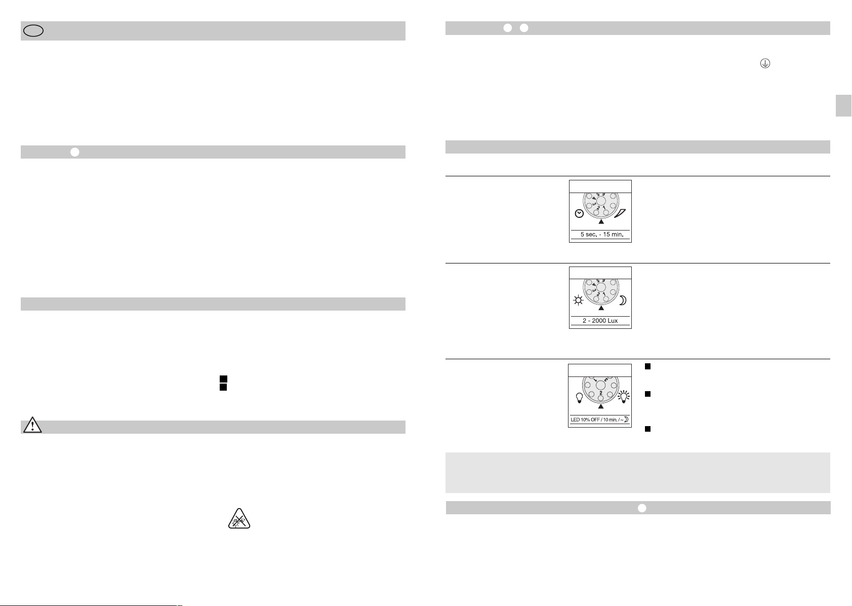
Traploos instelbare brandduur van 5 sec. – 15 min.
Instelknopje op 1 (linkeraanslag) = kortste tijd (5 sec.)
Instelknopje op 6 (rechteraanslag) = langste tijd (15 min.)
Bij de instelling van het registratiebereik wordt geadviseerd om de kortste tijd 1 te kiezen.
Traploos instelbare drempelwaarde van de sensor
van 2 – 2000 lux.
Instelknopje op 1 (linkeraanslag) = daglichtstand
ca. 2000 lux.
Instelknopje op 6 (rechteraanslag) = schemerstand
ca. 2 lux.
Voor de instelling van het registratiebereik bij daglicht
moet het instelknopje op 1 (daglichtstand) worden
gezet.
1
Lamp AAN bij beweging vanaf de ingestelde
schemerwaarde / geen basislichtsterkte.
2
Lamp AAN bij beweging vanaf de ingestelde
schemerwaarde / + basislichtsterkte (10%)
voor 10 min. na afloop van de ingestelde tijd.
3
Lamp AAN bij beweging vanaf een ingestelde
schemerwaarde / + basislichtsterkte (10%)
de hele nacht.
tijd, zie uitschakelvertraging ) naar het maximale
lichtvermogen (100 %) geschakeld. Daarna schakelt
de lamp voor 10 minuten weer terug naar de basislichtsterkte (ca. 10 %).
ken of met een schaar worden doorgeknipt. Na het
verwijderen van de bevestigingsring kunnen deze
boven in de sensorlens worden gehangen. De bevestigingsring daarna weer vastdraaien, zodat de afdekplaatjes vast verankerd worden.
Door het sensorhuis ± 80° te draaien, is bovendien
een fijnafstelling mogelijk.
- 19 -- 18 -
- 19 -
Permanente verlichting
ls er een netschakelaar in de kabel gemonteerd
A
ordt, zijn naast het eenvoudige in- en uitschakelen
w
ok de volgende functies mogelijk:
o
Sensormodus
1) Licht inschakelen (indien lamp UIT):
chakelaar 1 x UIT en AAN.
S
e LED's blijven gedurende de ingestelde tijd aan.
D
) Licht uitschakelen (indien lamp AAN):
2
chakelaar 1 x UIT en AAN.
S
De lamp gaat uit resp. schakelt over op sensormodus.
ermanente verlichting
P
) Permanente verlichting inschakelen:
1
chakelaar 2 x UIT en AAN. De lamp schakelt gedu-
S
ende 4 uur over op permanente verlichting (rode LED
r
achter de lens brandt). Vervolgens schakelt de lamp
automatisch weer over op sensormodus (rode LED uit).
2) Permanente verlichting uitschakelen:
chakelaar 1 x UIT en AAN. De lamp gaat uit resp.
S
chakelt over op sensormodus.
s
Belangrijk:
et meerdere malen op de schakelaar drukken moet
H
nel achter elkaar gebeuren (ca. 0,5 – 1 sec.).
s
Gebruik en onderhoud
Voor speciale inbraakalarminstallaties is het apparaat
niet geschikt, omdat de voorgeschreven sabotagebeveiliging hiervoor ontbreekt. Weersinvloeden kunnen
de werking van de sensor-LED-spot beïnvloeden. Bij
hevige windvlagen, sneeuw, regen of hagel kan een
foutieve schakeling voorkomen, omdat de plotselinge
temperatuurverschillen niet van warmtebronnen
onderscheiden kunnen worden.
De registratielens kan bij vervuiling met een vochtige
doek (zonder reinigingsmiddel) worden schoongemaakt.
Technische gegevens
Sensor-LED-spot XLed 10 XLed 25
Netaansluiting: 230-240 V, 50 Hz 230-240 V, 50 Hz
Vermogen: 10 LED's, ca. 30 W 25 LED's, ca. 62 W
Lichtkleur: ca. 4100 Kelvin (warm wit) ca. 4100 Kelvin (warm wit)
Lichtstroom: 2000 lumen 4000 lumen
Efficiëntie: 66,66 lm/W 64,52 lm/W
Extra schakelvermogen:
gloeilampen, max. 800 W bij 230 V AC
tl-buis, max. 400 W bij cos ϕ = 0,5,
inductieve belasting bij 230 V AC
tl-lampen, spaarlampen,
led-lampen met elektronisch voorschakelapparaat bij 230 V AC,
4 x max. 60 W, C ≤ 88 µF
Levensduur LED's: max. 50.000 uur (bij 3 uur/dag ca. 45 jaar)
Registratiehoek: 240° met onderkruipbescherming 240° met onderkruipbescherming
Registratiereikwijdte: 12 m rondom 12 m rondom
Verlicht oppervlak 250 cm2+ 103,36 cm
Draaibereik van de sensorunit: ± 80° ± 80°
Draaibereik behuizing: verticaal 200° verticaal 200°
horizontaal 270° horizontaal 270°
Tijdinstelling: 5 sec. – 15 min. 5 sec. – 15 min.
Schemerinstelling: 2 – 2000 lux 2 – 2000 lux
Basislichtsterkte: 10% de hele nacht / 10 min. / UIT 10% de hele nacht / 10 min. / UIT
Permanente verlichting: 4 uur instelbaar 4 uur instelbaar
Afmetingen (H x B x D): 205 x 200 x 200 mm 300 x 200 x 200 mm
Gewicht: 2200 g 2960 g
Temperatuurbereik: -20 °C tot +50 °C -20 °C tot +50 °C
Beschermingsgraad: IP 44 IP 44
Veiligheidsklasse: II
2
- 20 -
420 cm2+ 103,36 cm
2
Storingen
Storing
ensor-LED-spot zonder
S
etspanning
n
ensor-LED-spot schakelt niet aan
S
Sensor-LED-spot schakelt niet uit
Sensor-LED-spot schakelt steeds
AAN/UIT
Sensor-LED-spot schakelt
ongewenst aan
Oorzaak
Zekering defect, niet ingescha-
n
eld, kabel onderbroken
k
Kortsluiting
n
Bij daglicht, lichtinstelling staat
n
p schemerstand
o
Netschakelaar UIT
n
Zekering defect
n
Registratiebereik niet gericht
n
ingesteld
n Permanente beweging in het
registratiebereik
n Bewegende dieren in het
registratiebereik
n Wind beweegt bomen en struiken
binnen het registratiegebied
n Registratie van auto's op straat
n Plotselinge verandering van
temperatuur door het weer (wind,
regen, sneeuw) of afvoerlucht
van ventilatoren, open ramen
n De sensor-LED-spot trilt
(beweegt) door bijv. windvlagen
of sterke regen
Conformiteitsverklaring
Dit product voldoet aan de
- laagspanningsrichtlijn 2006/95/EG
- EMC-richtlijn 2004/108/EG
- RoHS-richtlijn 2011/65/EG
- WEEE-richtlijn 2012/19/EG.
Functiegarantie
Dit STEINEL-product is met grote zorgvuldigheid
gefabriceerd, getest op goede werking en veiligheid
volgens de geldende voorschriften, en vervolgens
steekproefsgewijs gecontroleerd. STEINEL verleent
garantie op de storingvrije werking.
De garantietermijn bedraagt 36 maanden en gaat in
op de datum van aanschaf door de klant. Alle klachten, die berusten op materiaal- of fabricagefouten,
worden door ons opgelost. De garantie bestaat uit
reparatie of vernieuwen van de defecte onderdelen,
door ons te beoordelen. Garantie vervalt bij schade
aan onderdelen, die aan slijtage onderhevig zijn en bij
schade of gebreken, die door ondeskundig gebruik of
onderhoud ontstaan. Schade aan andere voorwerpen
is uitgesloten van garantie.
Oplossing
n Nieuwe zekering, netschakelaar
inschakelen; kabel testen met
spanningstester
n Aansluitingen controleren
n Opnieuw instellen
n Inschakelen
n Nieuwe zekering, eventueel
aansluiting controleren
n Opnieuw instellen
n Bereik controleren en eventueel
opnieuw instellen of afdekken
n Sensor hoger draaien of gericht
afdekken; bereik veranderen of
afdekken
n Bereik veranderen
n Bereik veranderen
n Bereik veranderen of
montageplaats verleggen
n Monteer de sensor-LED-spot
op een vaste ondergrond
De garantie wordt alleen verleend wanneer het nietgedemonteerde apparaat met korte storingsbeschrijving, kassabon of rekening (koopdatum en winkelierstempel), goed verpakt naar het desbetreffende serviceadres wordt gestuurd.
Reparatieservice
Informeer na afloop van de garantietermijn of bij gebreken die niet onder
de garantie vallen bij het dichtstbijzijnde serviceadres naar de reparatiemogelijkheden.
- 21 -- 20 - - 21 -
NL
I
Istruzioni per il montaggio
Gentili Clienti,
i ringraziamo molto per la fiducia che ci avete dimostrato
V
cquistando il Vostro nuovo faretto LED a sensore della
a
TEINEL. Avete scelto un prodotto pregiato di alta qualità
S
che è stato costruito, provato ed imballato con la massima
scrupolosità.
Vi preghiamo di procedere all'installazione solo dopo aver
letto attentamente le presenti istruzioni di montaggio. Solo
n'installazione ed una messa in funzione effettuate a rego-
u
a d'arte possono infatti garantire un funzionamento affida-
l
ile, privo di disturbi e di lunga durata.
b
Vi auguriamo di essere pienamente soddisfatti del Vostro
nuovo faretto LED a sensore della STEINEL.
Installazione –
Il luogo di montaggio deve essere lontano almeno 50 cm
da un'altra eventuale lampada, in quanto il calore irradiato
otrebbe provocare un'attivazione del sistema. Per ottenere il
p
aggio d'azione indicato di 12 m, l'altezza di montaggio
r
ovrebbe essere di max. 2 m. Montate l'apparecchio su una
d
base stabile per evitare accensioni a sproposito.
Il cavo di collegamento alla rete ha 3 fili.
L = fase (di norma nero o marrone)
filo di neutro (di norma blu)
N =
E = conduttore di terra (verde/giallo)
P
mportante: se gli allacciamenti nell'apparecchio o nella
I
Vostra scatola dei fusibili vengono scambiati, ciò provoca in
un successivo momento un corto circuito. In questo caso è
necessario identificare i singoli cavi e rimontarli. Nella linea di
collegamento alla rete può venire installato un interruttore di
ete adeguato per l'accensione e lo spegnimento.
r
I
Il principio
Il movimento fa attivare la luce, l'allarme e molte altre cose.
Per il Vostro comfort e la Vostra sicurezza. Sia nel settore privato per l'illuminazione di casa e terreno circostante, sia nel
settore industriale, per es. per l'illuminazione dell'areale della
ditta, questo faretto LED a sensore può venire montato dappertutto con rapidità ed è subito pronto per l'esercizio.
I faretti LED a sensore XLed 10 e XLed 25 sono dotati di
due pirosensori a 120° che rilevano l'invisibile irraggiamento
termico di corpi in movimento (persone, animali, ecc). L'irraggiamento termico in tal modo rilevato viene trasformato
Descrizione apparecchio
Testina luminosa LED in flat design
Braccio snodato
Scanalature di raffreddamento
Supporto per il montaggio a parete con alimentatore
Unità sensore
Tappo di tenuta
Calotte di copertura
Avvertenze sulla sicurezza
n
Prima di effettuare qualsiasi lavoro interrompete l'alimentazione di corrente all'apparecchio!
n
Per il montaggio la linea elettrica da allacciare deve
essere fuori tensione. Prima del lavoro, occorre pertanto
togliere la tensione ed accertarne l'assenza mediante
uno strumento di misurazione della tensione.
n
L'installazione di questi apparecchi richiede un intervento sulla tensione di rete; essa deve venire pertanto eseguita a regola d'arte in base alle prescrizioni d'installazione vigenti nel relativo paese (
A
-ÖVE/ÖNORM E 8001-1, -SEV 1000)
D
-VDE 0100,
in energia elettrica e permette l'accensione del faretto. La
presenza di ostacoli quali muri o lastre di vetro impedisce il
rilevamento dell'irraggiamento termico. Con l'ausilio dei due
pirosensori viene raggiunto un angolo di rilevamento di
240° con un angolo di apertura di 180°.
Importante: il campo ottimale per i rilevamenti di movimento si ha quando l'apparecchio viene attivato lateralmente
rispetto alla direzione di movimento, senza che sull'area da
controllare ci siano ostacoli (come p.es. alberi, mura ecc.).
Il principio
Regolazione del periodo di accensione
Regolazione di luce crepuscolare
Impostazione della luminosità di base
Regolazione del raggio d'azione/Regolazione del
campo di rilevamento
Funzione luce continua
I
Allacciamento alla rete cavo sotto intonaco
Allacciamento alla rete cavo sopra intonaco
II
n
Non montate l'apparecchio su superfici di solito
facilmente infiammabili.
n
Adatto per esterni ed interni.
n
Il faretto LED a sensore è previsto solo per il montaggio
a muro e non per il montaggio a soffitto.
n
Durante il funzionamento l'involucro del faretto diventa
molto caldo. Per cambiare l'orientamento della testina
LED attendete sempre che si sia raffreddato.
n
- 22 -
Non guardate direttamente nella lampada LED
a breve distanza o per un periodo prlungato
(> 5 min.). La retina si potrebbe danneggiare.
Funzioni
Tutte le funzioni possono venire impostate quando la
calotta anulare è sfilata.
Ritardo di disinserimento
(impostazione del tempo di
accensione)
(impostazione da parte
del costruttore: 5 sec.)
Regolazione crepuscolare
(soglia di reazione)
(impostazione da parte del
costruttore: funzionamento con
luce diurna 2000 Lux)
Luminosità di base
(impostazione da parte del
costruttore: Programma 1)
Cos'è la luminosità di base?
La luminosità di base permette un'illuminazione ad una
potenza pari al 10 % circa del flusso luminoso utile. Solo in
caso di movimento all'interno del campo di rilevamento la
Impostazione del raggio d'azione/Regolazione
Il campo di rilevamento può venire ottimizzato a seconda
delle necessità. Le calotte di copertura fornite in dotazione
servono a coprire una quantità a piacere di segmenti di lente ossia a ridurre individualmente il raggio d'azione. In tal
modo è possibile escludere gli eventuali interventi a sproposito provocati ad esempio da automobili, passanti o sorvegliare in modo mirato punti particolarmente esposti al
pericolo. Le calotte di copertura possono venire separate
Durata del periodo di illuminazione a regolazione continua
tra 5 sec. e max. 15 min.
Regolatore posizionato su 1 (battuta sinistra) =
tempo minimo (5 sec.)
Regolatore posizionato su 6 (battuta destra) =
tempo massimo (15 min.)
Nella regolazione del campo di rilevamento si consiglia di
selezionare la durata minima 1.
Soglia d'intervento del sensore a regolazione continua da
2 a 2000 Lux.
Regolatore posizionato su 1 (battuta sinistra) =
funzionamento con luce diurna ca. 2000 Lux.
Regolatore posizionato su 6 (battuta destra) =
funzionamento con luce crepuscolare ca. 2 Lux.
Per l'impostazione del campo di rilevamento con luce
diurna si deve portare il regolatore su 1 (funzionamento
con luce diurna).
1
Faretto ON in caso di rilevamento di movimento a partire dal valore di luce crepuscolare impostato / no luminosità di base.
2
Faretto ON in caso di rilevamento di movimento a partire dal valore di luce crepuscolare impostato / + luminosità di base (10%) per 10 min. dopo la scadenza del
tempo impostato.
3
Faretto ON in caso di movimento a partire dal valore di
luce crepuscolare impostato / + luminosità di base
(10%) per tutta la notte.
luce passa (per il periodo impostato, vedi Ritardo dello spe-
gnimento
di ciò la lampada passa alla luminosità base (ca. 10 %).
) al massimo flusso luminoso utile (100%). Dopo
lungo le suddivisioni tramite scanalature già preparate in
verticale e in orizzontale o tagliate con una forbice. Dopo
aver sfilato la copertura anulare si deve appendere quest'ultima nella zona superiore della lente del sensore. Essa
deve poi venire di nuovo infilata, in modo tale che vengano
fissate definitivamente le calotte di copertura.
Inoltre, ruotando l'involucro di ± 80°
regolazione di precisione.
- 23 -- 22 -
- 23 -
è possibile una
Funzionamento con luce continua
e viene montato un interruttore di rete nella linea di allaccia-
S
ento alla rete, oltre alle semplici operazioni di accensione e
m
pegnimento sono possibili anche le seguenti funzioni:
s
Funzionamento del sensore
1) Accensione della luce (se il faretto è in posizione OFF):
nterruttore 1 x OFF e ON.
I
LED rimangono accesi per il periodo impostato.
I
) Spegnimento della luce (se il faretto è in posizione ON):
2
nterruttore 1 x OFF e ON.
I
Il faretto si spegne ossia passa in esercizio sensore.
unzionamento a luce continua
F
) Accensione della luce continua:
1
nterruttore 2 x OFF e ON. Il faretto rimane acceso con luce
I
ontinua per 4 ore (dietro la lente si illumina il LED rosso).
c
Dopo questo periodo di tempo la lampada passa di nuovo
automaticamente in esercizio sensore (il LED rosso si spegne).
2) Disattivazione della funzione luce continua:
nterruttore 1 x OFF e ON. Il faretto si spegne ossia passa in
I
sercizio sensore.
e
Importante:
'azionamento multiplo dell'interruttore deve avvenire rapida-
L
ente (entro 0,5 – 1 sec.).
m
Funzionamento e cura
L'apparecchio non è adatto all'applicazione in impianti di
allarme speciali (antifurto), in quanto non dispone della
sicurezza contro il sabotaggio prescritta per tali tipi di
impianto. Le condizioni atmosferiche possono influire sul
funzionamento del faretto LED a sensore. Forti raffiche di
vento, neve, pioggia e grandine possono attivare un'accensione indesiderata, dato che le fluttuazioni di temperatura
improvvise non possono essere distinte dalle fonti termiche.
In caso la lente di rilevamento fosse imbrattata, pulitela con
un panno umido (senza utilizzare detergenti).
Dati tecnici
Faretto LED a sensore XLed 10 XLed 25
Allacciamento alla rete: 230-240 V, 50 Hz 230-240 V, 50 Hz
Potenza: 10 LED, ca. 30 W 25 LED, ca. 62 W
Colore della luce: ca. 4100 Kelvin (bianco caldo) ca. 4100 Kelvin (bianco caldo)
Flusso luminoso: 2000 lumen 4000 lumen
Efficienza: 66,66 lm/W 64,52 lm/W
Potere di rottura aggiuntivo:
Lampadine, max. 800 W a 230 V AC
Tubo fluorescente, max. 400 W a cos ϕ = 0,5,
carico induttivo a 230 V AC
Lampade fluorescenti, lampade a basso consumo energetico,
lampade LED con ballast elettronico a monte a 230 V AC,
4 x max. 60 W cadauna, C ≤ 88 µF
Durata dei LED: fino a 50.000 ore (con 3 ore/giorno ca. 45 anni)
Angolo di rilevamento: 240° angolo di apertura, 240° angolo di apertura,
Raggio d'azione del rilevamento: 12 m tutt'attorno 12 m tutt'attorno
Superficie proiettata: 250 cm2+ 103,36 cm
Area di rotazione dell'unità sensore: ± 80° ± 80°
Area di rotazione dell'involucro: in verticale 200° in verticale 200°
Regolazione tempo: 5 sec. – 15 min. 5 sec. – 15 min.
Regolazione crepuscolare: 2 – 2000 Lux 2 – 2000 Lux
Luminosità di base: 10% per tutta la notte / 10 min / OFF 10% per tutta la notte / 10 min / OFF
Luce continua: regolabile fino a 4 ore regolabile fino a 4 ore
Dimensioni (A x L x P): 205 x 200 x 200 mm 300 x 200 x 200 mm
Peso: 2200 g 2960 g
Intervallo di variazione
della temperatura: da -20 °C a +50 °C da -20 °C a +50 °C
Tipo di protezione: IP 44 IP 44
Classe di protezione: II
con protezione dall'elusione del con protezione dall'elusione del
sensore nella zona sottostante sensore nella zona sottostante
2
in orizzontale 270° in orizzontale 270°
- 24 -
420 cm2+ 103,36 cm
2
Disturbi di funzionamento
Disturbo
aretto LED a sensore senza tensione
F
l faretto LED a sensore
I
on si accende
n
Il faretto LED a sensore non si spegne
Il faretto LED a sensore si accende e
spegne in continuazione
Il faretto LED a sensore interviene a
sproposito
Causa
usibile guasto, interruttore non
n
F
cceso, linea di alimentazione
a
nterrotta
i
orto circuito
n
C
n caso di funzionamento con
n
I
uce diurna la regolazione di luce
l
repuscolare è impostata, sul
c
unzionamento di notte
f
nterruttore di rete OFF
n
I
usibile difettoso
n
F
n
Campo di rilevamento non
impostato con direzione giusta
n
Continuo movimento all'interno
del campo di rilevamento
n
Animali in movimento nel campo
di rilevamento
n
Il vento muove alberi e cespugli
nel campo di rilevamento
n
Vengono rilevate automobili sulla
strada
n
Improvvisi sbalzi di temperatura
dovuti a condizioni atmosferiche
(vento pioggia, neve) o causati da
aria di scarico di ventilatori o da
aria proveniente da finestre aperte
n
Il faretto LED a sensore oscilla
(si muove) per es. in seguito a
raffiche di vento o a forti piogge
Rimedi
n
Nuovo fusibile, accendete
l'interruttore di rete; controllate il
cavo con un indicatore di tensione
n
Controllate gli allacciamenti
n
Eseguite una nuova impostazione
n
Accendete l'apparecchio
n
Cambiate fusibile, eventualmente
controllate l'allacciamento
n
Regolate nuovamente il campo
n
Controllate il campo di rilevamento,
eseguite eventualmente una nuova
regolazione o una schermatura
n
Posizionate il sensore più in alto e
provvedete all'applicazione mirata
di protezioni; cambiate la posizione
o coprite il campo di rilevamento
n
Spostate il campo
n
Spostate il campo
n
Scambiate luogo di montaggio
o impostatelo altrove
n
Montate il faretto LED a sensore
su una base stabile
Dichiarazione di conformità
Questo prodotto è conforme alle seguenti direttive:
- Direttiva sulla bassa tensione 2006/95/CE
- Direttiva sulla compatibilità elettromagnetica 2004/108/CE
- Direttiva sulla restrizione dell'uso di determinate sostanze pericolose nelle apparecchiature elettriche ed elet
troniche 2011/65/CE
- Direttiva RAEE 2012/19/CE
Garanzia di funzionamento
Questo prodotto STEINEL viene costruito con la massima
cura, con controlli di funzionamento e del grado di sicurezza
in conformità alle norme vigenti in materia; vengono poi effettuati collaudi con prove a campione. La STEINEL si assume la
garanzia di una fabbricazione ed un funzionamento perfetti.
La garanzia si estende a 36 mesi ed inizia il giorno d'acquisto
da parte dell'utilizzatore finale. Noi eliminiamo difetti riconducibili al materiale o alla fabbricazione; la prestazione della
garanzia consiste a nostra scelta nella riparazione o nella
sostituzione dei pezzi difettosi. Il diritto alla prestazione di
garanzia viene a decadere in caso di danni a pezzi soggetti
ad usura nonché in caso di danni o difetti che sono da ricondurre ad un trattamento inadeguato o ad una cattiva manutenzione. Sono esclusi dal diritto di garanzia gli ulteriori danni
conseguenti che si verificano su oggetti estranei.
La garanzia viene prestata solo se l'apparecchio viene inviato
non smontato, ben imballato e accompagnato da una breve
descrizione e dallo scontrino o dalla fattura (in cui siano indicati la data dell'acquisto e il timbro del rivenditore), al centro
di assistenza competente.
Centro assistenza tecnica:
In caso di periodo di garanzia scaduto o di
difetti che non danno diritto a prestazioni di
garanzia, siete pregati di informarvi presso
il centro di assistenza più vicino riguardo
alla possibilità di riparazione.
- 25 -- 24 - - 25 -
I
E
Instrucciones de montaje
Apreciado cliente:
racias por la confianza que nos ha dispensado al comprar
G
u nuevo foco Sensor LED STEINEL. Se ha decidido por un
s
roducto de alta calidad, producido, probado y embalado
p
con el mayor cuidado.
Le rogamos se familiarice con estas instrucciones de mon-
aje antes de instalarlo. Solo una instalación y puesta en
t
uncionamiento adecuadas garantizarán un servicio prolon-
f
ado, eficaz y sin alteraciones.
g
Le deseamos que disfrute durante mucho tiempo de su
nuevo foco Sensor LED STEINEL.
Instalación –
El lugar de montaje debe hallarse a una distancia mínima de 50 cm de cualquiera lámpara debido a que la
adiación térmica de la misma puede hacer que se active
r
rróneamente el sensor. Para conseguir el alcance máx. de
e
2 m indicado, la altura de montaje debe ser de aprox.
1
2 m. Monte el aparato sobre una base firme para evitar
conmutaciones incorrectas.
El cable de alimentación de red consta de un conductor
rifilar:
t
L = fase (generalmente negro o marrón)
neutro (generalmente azul)
N =
E = toma de tierra (verde/amarillo)
P
mportante: La inversión de las conexiones producirá un
I
cortocircuito en el aparato o en su caja de fusibles. En tal
caso habrá que identificar cada uno de los conductores y
montarlos de nuevo. El cable de alimentación de red puede
llevar montado un interruptor adecuado para conectar y
esconectar la tensión.
d
E
El concepto
El movimiento enciende la luz y activa la alarma, entre otras
funciones, para su comodidad y seguridad. Tanto en el
ámbito privado, para el alumbrado de la casa o la finca,
como en el ámbito industrial, p. ej. para el alumbrado del
recinto de una empresa, este foco Sensor LED se monta y
está listo para funcionar rápidamente en cualquier lugar.
Los focos Sensor LED XLed 10 y XLed 25 están dotados de
dos sensores piroeléctricos de 120° que registran la radiación térmica invisible de cuerpos en movimiento (personas,
animales, etc.). Esta radiación térmica registrada se transforma electrónicamente, activando automáticamente el foco.
Descripción del aparato
Cabezal LED de diseño plano
Brazo articulado
Aletas de refrigeración
Soporte mural con fuente de alimentación
Unidad del sensor
Tapón obturador
Cubiertas
Indicaciones de seguridad
n
¡Antes de comenzar cualquier trabajo en el aparato,
debe interrumpirse la alimentación de tensión!
n
Para el montaje, el cable eléctrico a enchufar deberá
estar sin tensión. Por tanto, desconecte primero la
corriente y compruebe que no hay tensión utilizando un
comprobador de tensión.
n
La instalación de estos aparatos supone un trabajo en la
red eléctrica; por ello tiene que realizarse profesionalmente según las prescripciones de instalación y condiciones de conexión específicas de cada país (
A
-ÖVE/ÖNORM E 8001-1, -SEV 1000)
0100,
D
-VDE
Debido a los obstáculos, como p. ej. paredes o cristales,
no se detecta ninguna radiación térmica. A base de los dos
sensores piroeléctricos se consigue un ángulo de detección
de 240° con un ángulo de apertura de 180°.
Importante: La detección de movimientos más segura se
consigue montando el aparato lateralmente con relación al
sentido del movimiento y evitando todo tipo de objetos que
obstaculicen la visión de los sensores (tales como árboles,
muros etc.).
El concepto
Temporización
Regulación crepuscular
Regulación de luz de cortesía
Regulación del alcance/ajuste del campo de detección
Función de alumbrado permanente
I
Conexión de red línea de alimentación empotrada
Conexión de red línea de alimentación de superficie
II
n
No monte el aparato sobre superficies que habitualmente sean fácilmente inflamables.
n
Es apto para espacios de interior y de exterior.
n
El foco Sensor LED está previsto solo para el
montaje en la pared y no para el montaje en el techo.
n
La carcasa del foco se calienta durante su funcionamiento. El cabezal LED solo debe moverse para orientarlo
cuando esté frío.
n
No mire a la lámpara LED desde cerca ni
durante un periodo prolongado (> 5 min.).
Si lo hace podría sufrir lesiones en la retina.
Funciones
Todas las funciones pueden regularse con el anillo de
protección extraído.
Desconexión diferida
(temporización)
(Regulación de fábrica: 5 seg.)
Regulación crepuscular
(umbral de respuesta)
(Regulación de fábrica:
funcionamiento a la luz del
día 2000 lux)
Luz de cortesía
(Rgulación de fábrica: Programa 1)
¿Qué es la luz de cortesía?
La luz de cortesía permite una iluminación con un 10%
aprox. de potencia luminosa. Con un movimiento dentro del
campo de detección se enciende la luz (para la temporiza-
Regulación del alcance/ajuste
El campo de detección puede optimizarse según necesidad. Las cubiertas adjuntas sirven para cubrir tantos segmentos individuales de lentes como se desee, o bien para
acortar individualmente el alcance de detección. De este
modo se evitan conmutaciones erróneas debido al paso de
vehículos, transeúntes, etc. y se vigilan las zonas de peligro
de forma precisa. Las cubiertas pueden separarse o cortar-
Temporización con regulación continua de 5 seg. a 15 min.
Tornillo de regulación ajustado a 1 (tope izquierdo) =
tiempo más corto (5 seg.)
Tornillo de regulación ajustado a 6 (tope derecho) =
tiempo más largo (15 min.)
Para la regulación del campo de detección se recomienda
seleccionar el tiempo más corto 1.
Umbral de respuesta con regulación continua del sensor
de 2 – 2000 lux.
Tornillo de regulación ajustado a 1 (tope izquierdo) =
funcionamiento a la luz del día, aprox. 2000 lux.
Tornillo de regulación ajustado a 6 (tope derecho) =
funcionamiento crepuscular, aprox. 2 lux.
Para la regulación del campo de detección con luz diurna,
el tornillo de regulación debe ponerse a 1 (funcionamiento
a la luz del día).
1
Foco ON al producirse un movimiento a partir del
valor crepuscular ajustado / sin luz de cortesía.
2
Foco ON al producirse un movimiento a partir del
valor crepuscular ajustado / + luz de cortesía (10%)
durante 10 min. después de transcurrido el tiempo
ajustado.
3
Foco ON al producirse movimiento a partir del
valor crepuscular ajustado / + luz de cortesía (10%)
durante toda la noche.
ción regulada, véase desconexión diferida
luminosa máxima (100%). Después la lámpara conmuta
durante 10 min. a la luz de cortesía (aprox. 10%).
se con una tijera vertical u horizontalmente a lo largo de las
divisiones preranuradas. Tras retirar el anillo de protección,
se han de colgar en la parte superior del lente del sensor.
Acto seguido se ha de colocar de nuevo el anillo de protección, quedando firmemente sujetas las cubiertas.
Además se puede realizar una regulación de precisión,
girando la carcasa del sensor en ± 80°
) a la potencia
.
- 26 -
- 27 -- 26 -
- 27 -
Función de alumbrado permanente
i se monta un interruptor en el cable de alimentación de red,
S
demás de la simple función de encendido y apagado puede
a
isponerse de las siguientes funciones:
d
Funcionamiento de sensor
1) Encender la luz (si el foco está en OFF):
ulse el interruptor OFF y ON una vez.
P
os LED quedan encendidos durante el tiempo preajustado.
L
) Apagar la luz (si el foco está en ON):
2
ulse el interruptor OFF y ON una vez.
P
El foco se apaga o pasa a funcionamiento de sensor.
lumbrado permanente
A
) Conectar alumbrado permanente:
1
ulse el interruptor OFF y ON dos veces. El foco se
P
nciende de modo permanente por un período de 4 horas
e
(se enciende el LED rojo que hay detrás del lente). A continuación pasa de nuevo automáticamente a funcionamiento
de sensor (el LED rojo se apaga).
) Desconectar alumbrado permanente:
2
ulse el interruptor OFF y ON una vez. El foco se apaga o
P
pasa a funcionamiento de sensor.
mportante:
I
a secuencia de pulsación del interruptor debe ser rápida
L
(del orden de 0,5 a 1 seg.).
Funcionamiento y mantenimiento
No es apto para alarmas antirobo especiales debido a que
carece de la seguridad antisabotaje prescrita para las mismas. Las condiciones atmosféricas pueden afectar al funcionamiento del foco Sensor LED. Fuertes ráfagas de viento, la
nieve, la lluvia y el granizo pueden provocar una activación
errónea al no poder distinguir entre cambios de temperatura
repentinos y fuentes térmicas.
El lente de detección puede limpiarse con un paño húmedo
(sin detergente) cuando esté sucio.
Datos técnicos
Foco Sensor LED XLed 10 XLed 25
Tensión de red: 230-240 V, 50 Hz 230-240 V, 50 Hz
Potencia: 10 LED, aprox. 30 W 25 LED, aprox. 62 W
Color de luz: aprox. 4100 Kelvin (blanco cálido) aprox. 4100 Kelvin (blanco cálido)
Flujo luminoso: 2000 lumen 4000 lumen
Eficiencia: 66,66 lm/W 64,52 lm/W
Potencia de ruptura adicional:
Lámparas incandescentes, máx. 800 W con 230 V AC
Tubo fluorescente, máx. 400 W con cos ϕ = 0,5,
carga inductiva con 230 V AC
Lámparas fluorescentes, lámparas de bajo consumo,
lámparas LED con regulador electrónico de tensión con 230 V AC,
4 x máx. 60 W, C ≤ 88 µF
Duración de los LED: hasta 50.000 h (a 3 h/día aprox. 45 años)
Ángulo de detección: 240° con protección contra sumersión 240° con protección contra sumersión
Alcance de detección: 12 m omnidireccionales 12 m omnidireccionales
Superficie proyectada: 250 cm2+ 103,36 cm
Girabilidad de la unidad
del sensor: ± 80° ± 80°
Girabilidad de la carcasa: vertical 200° vertical 200°
horizontal 270° horizontal 270°
Temporización: 5 seg. – 15 min. 5 seg. – 15 min.
Regulación crepuscular: 2 – 2000 lux 2 – 2000 lux
Luz de cortesía: 10% toda la noche / 10 min. / OFF 10% toda la noche / 10 min. / OFF
Alumbrado permanente: conmutable 4 h conmutable 4 h
Dimensiones (al. x an. x prof.) 205 x 200 x 200 mm 300 x 200 x 200 mm
Peso: 2200 g 2960 g
Campo de temperatura: -20 °C a +50 °C -20 °C a +50 °C
Tipo de protección: IP 44 IP 44
Clase de protección: II
2
- 28 -
420 cm2+ 103,36 cm
2
Este producto cumple con la
- Directiva de baja tensión 2006/95/CE
- Directiva CEM 2004/108/CE
- Directiva RoHS 2011/65/CE
- Directiva RAEE 2012/19/CE
Este producto STEINEL ha sido elaborado con el máximo
esmero, habiendo pasado los controles de funcionamiento
y seguridad previstos por las disposiciones vigentes, así
como un control adicional de muestreo al azar. STEINEL
garantiza el perfecto estado y funcionamiento.
El período de garantía es de 36 meses comenzando el día
de la venta al consumidor y cubre los defectos de material
y fabricación. La prestación de la garantía se efectúa
mediante la reparación o el cambio de las piezas defectuosas a elección de STEINEL. La prestación de garantía queda anulada para daños producidos en piezas de desgaste
y daños y defectos originados por uso o mantenimiento
inadecuados. Quedan excluidos de la garantía los daños
consecuenciales causados en objetos ajenos.
Fallos de funcionamiento
Fallo
oco Sensor LED sin tensión
F
El foco Sensor LED no se enciende
El foco Sensor LED no se apaga
El foco Sensor LED
se enciende y apaga continuamente
El foco Sensor LED
se enciende cuando no se desea
Declaración de conformidad
Garantía de funcionamiento
Causa Solución
ambiar fusible, poner interruptor
n
n
fusible defectuoso, interruptor en
OFF, línea interrumpida
n
cortocircuito
n
en funcionamiento a la luz del día,
regulación crepuscular regulada
solo para funcionamiento nocturno
n
interruptor en OFF
n
fusible defectuoso
n
campo de detección sin ajuste
selectivo
n
movimiento permanente en el
campo de detección
n
animales en movimiento en el
campo de detección
n
el viento mueve árboles y matorrales en el campo de detección
n
detección de automóviles en la calle
n
cambio de temperatura repentino
debido a las condiciones atmosféricas (viento, lluvia, nieve) o a ventiladores o ventanas abiertas
n
el foco Sensor LED oscila
(se mueve), p. ej. por las ráfagas
de viento o precipitaciones fuertes
Solo se concede la garantía si se envía el aparato sin
desarmar con una breve descripción del fallo, ticket de caja
o factura (con fecha de compra y sello del comercio), bien
empaquetado, al centro de servicio correspondiente.
Servicio de reparación:
Una vez transcurrido el período de
garantía o en caso de defectos no
cubiertos por la misma, consulte una
posible reparación con su centro de
servicio más próximo.
- 29 -- 28 - - 29 -
c
n ON; comprobar la línea de ali-
e
entación con un comprobador
m
e tensión
d
omprobar conexiones
n
c
olver a ajustar
n
v
onectar
n
c
ambiar fusible y dado el caso
n
c
omprobar conexión
c
n
volver a regular
n
controlar el campo de detección
y dado el caso ajustar de nuevo
o bien cubrir partes del sensor
n
girar el sensor más hacia arriba
o cubrir partes del sensor selectivamente; reajustar el campo de
detección o utilizar cubiertas
n
modificar campo de detección
n
modificar campo de detección
n
modificar campo de detección,
cambiar lugar de montaje
n
montar el foco Sensor LED sobre
una base firme
E
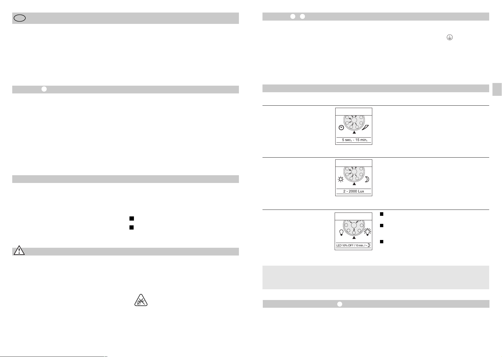
P
Instruções de montagem
Estimado cliente
gradecemos-lhe a confiança depositada em nós ao comprar
A
novo projetor LED com sensor da STEINEL. Trata-se de um
o
roduto de elevada qualidade produzido, testado e embalado
p
com o máximo cuidado.
Procure familiarizar-se com estas instruções de montagem
antes da instalação. Só uma instalação e colocação em
uncionamento corretas podem garantir a longevidade do
f
roduto e um funcionamento fiável e isento de falhas.
p
Fazemos votos que tenha prazer ao trabalhar com o seu
novo projetor LED com sensor da STEINEL.
Instalação –
O local de montagem deve encontrar-se a uma distância
ínima de 50 cm de outro candeeiro, pois a radiação tér-
m
ica pode ocasionar a ativação errada do sensor. A altura de
m
ontagem não deve ultrapassar aprox. 2 m, para obter o
m
lcance máximo de 12 m. Monte o aparelho sobre uma
a
superfície firme para evitar ligações erradas.
O cabo proveniente da rede é formado por um conjunto
de 3 fios:
L = fase (geralmente preto ou castanho)
neutro (geralmente azul)
N =
E = condutor terra (verde/amarelo)
P
mportante: a troca dos conectores provocará mais tarde um
I
curto-circuito no aparelho ou na caixa dos fusíveis. Nesse
caso, os diversos fios terão de ser identificados e montados
de novo. No cabo de rede pode ser montado um interruptor
de rede apropriado do tipo "ligar - desligar".
O princípio
O movimento aciona a luz, o alarme e muitas outras coisas,
para seu conforto e para a sua segurança. Seja a nível privado, para iluminar o seu quintal e o terreno ou na área comercial, por ex. para iluminar o terreno da empresa, este projetor
LED com sensor pode ser montado em qualquer lugar com
rapidez e facilidade, ficando logo pronto a funcionar.
Os projetores LED com sensor XLed 10 e XLed 25 estão
equipados com dois sensores pirelétricos de 120° que detetam a radiação térmica invisível de corpos em movimento
(pessoas, animais, etc.). Esta radiação térmica detetada é
transformada por via eletrónica e liga o projetor.
Descrição do aparelho
Cabeça LED com design plano
Braço articulado
Dissipadores de calor
Suporte de fixação à parede com alimentador de rede
Unidade sensórica
Bujão vedante
Palas
Considerações em matéria de segurança
n
Antes de executar qualquer trabalho no aparelho,
desligue-o da corrente!
n
Durante a montagem, o cabo elétrico a conectar
deve estar isento de tensão. Para tal, desligue primeiro
da corrente e verifique se não há tensão, usando o
busca-pólos.
n
A instalação do sensor consiste essencialmente em lidar
com tensão de rede. Por esse motivo, terá de ser realizada
de forma profissional segundo as respetivas prescrições de
instalação e condições de conexão habituais nos diversos
D
países (
-VDE 0100, A-ÖVE/ÖNORM E 8001-1,
-SEV 1000).
A radiação térmica não é detetável através de obstáculos,
tais como, por ex., paredes ou vidros. Os dois sensores pirelétricos cobrem um ângulo de deteção de 240º, com um
ângulo de abertura de 180º.
Importante: será possível detetar os movimentos de forma
mais segura se o aparelho estiver instalado lateralmente em
relação ao sentido de aproximação e se não houver obstáculos (como por ex. árvores, muros, etc.), que impeçam a captação pelo sensor.
O princípio
Ajuste do tempo
Regulação crepuscular
Regulação da luminosidade básica
Ajuste do alcance/ajuste da área de deteção
Função de luz permanente
I
Ligação à rede elétrica cabo proveniente
da rede embutido
II
Ligação à rede elétrica cabo proveniente
da rede saliente
n
Não monte o aparelho em cima de superfícies
facilmente inflamáveis.
n
Apropriado para aplicações no interior e exterior.
n
O projetor LED com sensor é indicado apenas para a
montagem na parede e não para a montagem no teto.
n
Em funcionamento, o corpo do projetor aquece. Alinhar
a cabeça LED apenas quando esta estiver fria.
n
Não olhe diretamente para o candeeiro LED,
nem por demasiado tempo (>5 min.).
O desrespeito a esta indicação pode causar
lesões na retina.
Funções
Todas as funções podem ser ajustadas depois de retirar
o friso anelar.
Retardamento na inativação
(Ajuste do tempo)
(Regulação de fábrica: 5 s)
Regulação crepuscular
(Limiar de resposta)
(Regulação de fábrica:
regime diurno 2000 lux)
Luminosidade básica
(Regulação de fábrica: programa 1)
O que significa luminosidade básica ?
A luminosidade básica permite a iluminação com aprox.
10 % da potência luminosa. A luz só se acende (pelo tempo
predefinido, v. retardamento na inativação
Regulação do alcance / Ajuste
Consoante a necessidade, a área de deteção pode ser ajustada com precisão. As palas fornecidas servem para cobrir o
número de segmentos de lente necessários para reduzir o
alcance conforme se deseja. Deste modo, podem evitar-se
ativações erradas provocadas por ex. por automóveis,
pessoas a passar, etc. ou então monitorar pontos de perigo
específicos. As palas podem ser separadas pelas divisões
) com
Duração da luz da lâmpada progressivamente regulável de
5 s a 15 min.
Regulador no número 1 (limite esquerdo) =
tempo mais curto (5 s).
Regulador no número 6 (limite direito) =
tempo mais longo (15 min).
Ao determinar a área de deteção é recomendável escolher o
tempo mais curto 1.
O limiar de resposta do sensor pode ser regulado progressivamente de 2 a 2000 lux.
Regulador no número 1 (limite esquerdo) =
regime diurno (aprox. 2000 lux).
Regulador no número 6 (limite direito) =
regime crepuscular (aprox. 2 lux).
Para regular a área de deteção à luz do dia, o regulador tem
de estar em 1 (regime diurno).
1
Projetor LIGA ao detetar movimento a partir do limiar crepuscular definido / sem luminosidade básica.
2
Projetor LIGA ao detetar movimento a partir do limiar crepuscular definido / + luminosidade básica (10%) durante
10 min. depois de decorrido o tempo definido.
3
Projetor LIGA a partir do valor crepuscular predefinido / +
luminosidade básica (10%) noite inteira.
potência luminosa máxima (100 %) ao ser detetado um
movimento dentro da área de deteção. A seguir, a lâmpada
volta por 10 min. para a luminosidade básica (aprox. 10 %).
pré-marcadas ou cortadas com uma tesoura, quer na horizontal quer na vertical. Depois de retirar o friso anelar, as
palas devem ser engatadas na parte superior da lente do
sensor. Depois de voltar a colocar o friso anelar, as palas
ficam fixadas.
Rodando a caixa do sensor em ± 80 °
também um ajuste preciso.
- 31 -- 30 -
- 31 -
pode realizar-se
P
Função de iluminação permanente
e for montado um interruptor de corrente no cabo prove-
S
iente da rede, além das meras funções de ligar e desligar
n
o candeeiro conectado, ainda são possíveis as funções
d
seguidamente enunciadas:
Funcionamento do sensor
) Ligar a luz (estando o projetor DESLIGADO):
1
nterruptor 1 vez DESLIGA e LIGA.
I
EDs continuam acesos durante o tempo predefinido.
L
) Apagar a luz (estando o projetor LIGADO):
2
Interruptor 1 vez DESLIGA e LIGA.
O projetor desliga-se ou passa para o funcionamento
de sensor.
uncionamento de luz permanente
F
) Ligar a luz permanente:
1
nterruptor 2 vezes DESLIGA e LIGA. O projetor é ligado por
I
horas em modo de luz permanente (LED vermelho por
4
detrás da lente acende-se). A seguir, passa automaticamente
para o funcionamento de sensor (LED vermelho apaga-se)
2) Desligar a luz permanente:
nterruptor 1 vez DESLIGA e LIGA. O projetor desliga-se ou
I
assa para o funcionamento de sensor.
p
Importante:
o acionar o interruptor várias vezes seguidas, os intervalos
A
evem ser mínimos (na ordem de 0,5 – 1 s).
d
Funcionamento e conservação
O aparelho não se adequa a sistemas de alarme anti-roubo
especiais, uma vez que não está garantida a proteção contra
sabotagem exigida por lei. As influências climatéricas podem
deteriorar o funcionamento do projetor LED com sensor. As
rajadas fortes de vento, a neve, a chuva e o granizo podem
causar uma ativação errada, porque o sistema não consegue
distinguir entre alterações súbitas de temperatura e irradiação
proveniente de fontes de calor.
Se estiver suja, a lente de deteção pode ser limpa com um
pano húmido (sem usar produtos de limpeza).
Dados técnicos
Projetor LED com sensor XLed 10 XLed 25
Ligação à rede: 230-240 V, 50 Hz 230-240 V, 50 Hz
Potência: 10 LEDs, aprox. 30 W 25 LEDs, aprox. 62 W
Cor de luz: aprox. 4100 Kelvin (branco quente) aprox. 4100 Kelvin (branco quente)
Intensidade da luz: 2000 lúmenes 4000 lúmenes
Eficiência: 66,66 lm/W 64,52 lm/W
Potência de comutação suplementar:
Lâmpadas incandescentes, máx. 800 watts a 230 V CA
Tubo fluorescente, máx. 400 watts com cos ϕ = 0,5,
carga indutiva a 230 V CA
Lâmpadas fluorescentes, lâmpadas economizadoras,
candeeiros LED com balastro electrónico a 230 V CA,
4 x máx. de 60 watts cada, C ≤ 88 µF
Vida útil dos LEDs: até 50 000 h (assumindo 3 h/dia aprox. 45 anos)
Ângulo de deteção: 240° com proteção contra 240º com proteção contra
Alcance de deteção: num raio de 12 m num raio de 12 m
Área projetada: 250 cm2+ 103,36 cm
Orientação da unidade sensórica: ± 80° ± 80°
Margem de orientação da caixa: vertical 200° vertical 200°
Ajuste do tempo: 5 s – 15 min 5 s – 15 min
Regulação crepuscular: 2 – 2000 lux 2 – 2000 lux
Luminosidade básica: 10% toda a noite / 10 min. / DESLIGADO 10% toda a noite / 10 min. / DESLIGADO
Luz permanente: regulável até 4 h regulável até 4 h
Dimensões (a x l x p): 205 x 200 x 200 mm 300 x 200 x 200 mm
Peso: 2200 g 2960 g
Intervalo de temperatura: -20 °C até +50 °C -20 °C até +50 °C
Grau de proteção: IP 44 IP 44
Classe de proteção: II
movimentos dissimulados movimentos dissimulados
2
horizontal 270° horizontal 270°
420 cm2+ 103,36 cm
2
Falhas de funcionamento
Falha
rojetor LED com sensor
P
em tensão
s
projetor LED com sensor
O
ão se acende
n
O projetor LED com sensor
não se apaga
O projetor LED com sensor
está sempre a acender/apagar
O projetor LED com sensor
acende-se inadvertidamente
Causa
usível queimado, não ligado,
n
F
igação interrompida
l
urto-circuito
n
C
m regime diurno, regulação cre-
n
E
uscular encontra-se em regime
p
oturno
n
nterruptor de rede DESLIGADO
n
I
usível fundido
n
F
n
Área de deteção ajustada
incorretamente
n
Movimento constante na área
de deteção
n
Encontram-se animais dentro
da área de deteção
n
O vento agita árvores e arbustos na
área de deteção
n
São detetados automóveis a passar
na estrada
n
Alteração térmica súbita devido a
influências climatéricas (vento, chuva, neve) ou ar evacuado de ventiladores, janelas abertas
n
Projetor LED com sensor oscila
(mexe-se) por ex. devido a rajadas
de vento ou chuva forte.
Solução
n
n
n
n
n
n
n
n
n
n
n
n
Declaração de conformidade
O produto cumpre as Diretivas do Conselho
- "Baixa tensão" 2006/95/CE
- "Compatibilidade eletromagnética" 2004/108/CE
- "Redução de substâncias perigosas" 2011/65/CE
- "Diretiva REEE" (Resíduos de Equipamentos Elétricos e Eletrónicos) 2012/19/CE
Garantia de funcionamento
Este produto STEINEL foi fabricado com todo o zelo e o seu
funcionamento e segurança verificados, de acordo com as
normas em vigor, e sujeito a um controlo por amostragem
aleatória. A STEINEL garante o bom estado e o bom funcionamento do aparelho.
O prazo de garantia é de 36 meses a contar da data de compra. Eliminamos falhas relacionadas com defeitos de material
ou de fabrico. A garantia inclui a reparação ou a substituição
das peças com defeito, de acordo com o nosso critério,
estando excluídas as peças sujeitas a desgaste, os danos e
as falhas originados por uma utilização ou manutenção incorreta. Excluem-se igualmente os danos provocados noutros
objetos estranhos ao aparelho.
Os serviços previstos na garantia só serão prestados caso o
aparelho seja apresentado bem embalado no respetivo serviço de assistência técnica, devidamente montado e acompanhado do talão da caixa ou da fatura (data da compra
e carimbo do revendedor) e de uma pequena descrição do
problema.
Serviço de reparação:
Depois de expirado o prazo de garantia,
ou em caso de falha não abrangida pela
garantia, contacte o serviço de assistência
técnica mais próximo de si para saber
quais são as possibilidades de reparação.
Fusível novo, ligar interruptor de
rede; verificar o cabo com detetor
de tensão
Verificar as conexões
Reajustar
Ligar
Fusível novo, verificar
eventualmente a conexão
Reajustar
Examinar a área e eventualmente
reajustar ou cobrir com pala
Virar o sensor para cima ou tapar
determinadas partes; mudar a área
de deteção ou cobrir com pala
Modificar a área
Modificar a área
Modificar a área, mudar para outro
local de montagem
Montar o projetor LED com
sensor numa base firme
P
- 32 -
- 33 -- 32 - - 33 -
 Loading...