

STEINEL HF 360 COM 2, DUAL HF COM 1 AP, DUAL HF DIM, HF 360 COM 1, HF 360 DIM User Manual
...Page 1
D
STEINEL-Schnell-Service
Dieselstraße 80-84 · 33442 Herzebrock-Clarholz
Tel: +49/5245/448-188 · Fax:+49/5245/448-197 · www.steinel.de
A
I. MÜLLER
Peter-Paul-Str. 15 · A-2201 Gerasdorf bei Wien
Tel.: +43/2246/2146 · Fax: +43/2246/25466 · www.imueller.at
PUAG AG
Oberebenestrasse 51 · CH-5620 Bremgarten
Tel.: +41/56/6488888 · Fax: +41/56/6488880 · www.puag.ch
STEINEL U.K. LTD.
25, Manasty Road · Axis Park · Orton Southgate
GB-Peterborough Cambs PE2 6UP · Tel.: +44/1733/366-700
Fax: +44/1733/366-701 · www.steinel.co.uk
STC SOCKET TOOL COMPANY Limited
8, Queen Street, Smithfield · IRL-Dublin 7
Tel.: +353/1/8725433 · Fax: +353/1/8725195
sockettool@eircom.net
F
DUVAUCHEL S.A.
ACTICENTRE - CTR 2
Rue des Famards - Bat. M - Lot 3 · F-59818 Lesquin Cedex
Tél.: +33/3/20 3034 00 · Fax: +33/3/2030 34 20
info@steinelfrance.com
VAN SPIJK AGENTUREN
Postbus 2 · 5688 HP OIRSCHOT
De Scheper 260 · 5688 HP OIRSCHOT
Tel. 0499 571810 · Fax. 0499 575795
vsa@vanspijk.nl · www.vanspijk.nl
B
VSA handel Bvba
Hagelberg 29 · B-2440 Geel
Tel.: +32/14/256050 · Fax: +32/14/256059 · www.vsahandel.be
L
A. R. Tech.
19, Rue Eugène Ruppert, Cloche D’Or · BP 1044
L-1010 Luxembourg
Tel.: +352/49/3333 · Fax: +352/40/2634 · www.artech.lu
I
STEINEL Italia S.r.l.
Largo Donegani 2 · I-20121 Milano
Tel.: +39/02/96457231 · Fax: +39/02/96459295 · www.steinel.it
E
SAET-94 S.L.
C/ Trepadella, n° 10 · Pol. Ind. Castellbisbal Sud
E-08755 Castellbisbal (Barcelona)
Tel.: +34/93/772 28 49 · Fax: +34/93/772 01 80 · www.saet94.com
P
PRONODIS - Sol. Tec., Lda
Zona Industrial Vila Verde Sul, Lt 14
P-3770-305 Oliveira do Bairro
Tel.: +351/234/484031 · Fax: +351/234/484033 ·
www.
pronodis.pt
S
KARL H STRÖM AB
Verktygsvägen 4 · S-55302 Jönköping
Tel.: +46/36/31 42 40 · Fax: +46/36/31 42 49 · www.khs.se
BROMMANN ApS
Ellegaardvej 18 · DK-6400 Sønderborg
Tel.: +45 74428862 · Fax: +45 74434360 · www.brommann.dk
Oy Hedtec Ab
Hedengren yhtiö · Lauttasaarentie 50 · FIN-00200 Helsinki
Tel.: +358/9/682881 · Fax: +358/9/673813 · www.hedtec.fi/valaistus
N
Vilan AS
Tvetenveien 30 B · N-0666 Oslo
Tel.: +47/22725000 · Fax: +47/22725001 · www.vilan.no
PANOS Lingonis + Sons O. E.
Aristofanous 8 Str. · GR-10554 Athens
Tel.: +30/210/3212021 · Fax: +30/210/3218630
lygonis@otenet.gr
EGE SENSÖRLÜ AYDİNLATMA İTH. İHR.
TİC. VE PAZ. Ltd. STİ.
Gersan Sanayi Sitesi 659
Sokak No. 510 · TR-06370 Bati Sitesi (Ankara)
Tel.: +90/312/2571233 · Fax: +90/312/2556041
ege@egeaydinlatma.com · www.egeaydinlatma.com
ATERSAN İTHALAT MAK. İNŞ. TEKNIK
MLZ. SAN. ve TİC. A.Ş.
Tersane Cad. No: 63 · TR-34420 Karaköy/‹stanbul
Tel. +90/212/2920664 Pbx. · Fax. +90/212/2920665
info@atersan.com · www.atersan.com
ELNAS s.r.o.
Oblekovice 394 · CZ-67181 Znojmo
Tel.: +420/515/220126 · Fax: +420/515/244347
www.elnas.cz
LANGE ŁUKASZUK Sp.j.
Byków, ul. Wrocławska 43 · PL-55-095 Mirków
Tel.: +48/71/3980861 · Fax: +48/71/3980819
www.langelukaszuk.pl
H
DINOCOOP Kft
Radvány u. 24 · H-1118 Budapest
Tel.: 36/1/3193064 · Fax: +36/1/3193066
www.dinocoop.hu
KVARCAS
Neries krantine 32 · LT-48463, Kaunas
Tel.: +370/37/408030 · Fax: +370/37/408031 ·
www.
kvarcas.lt
FORTRONIC AS
Teguri 45c · EST 51013 Tartu
Tel.: +372/7/475208 · Fax: +372/7/367229 ·
www.
fortronic.ee
LOG Zabnica D.O.O.
Podjetje Za Trgovino · Srednje Bitnje 70
SLO-4209 Zabnica
Tel.: +386/42/312000 · Fax: +386/42/312331 ·
www.
log.si
Neco s.r.o.
Ružová ul. 111 · SK-01901 Ilava
Tel.: +421/42/4 45 67 10 · Fax: +421/42/4 45 67 11
www.neco.sk
Steinel Distribution SRL
Parc industial Metrom · RO - 500269 Brasov
Str. Carpatilor nr. 60
Tel.: + 40(0)268 53 00 00 · Fax: + 40(0)268 53 11 11
www.steinel.ro
Daljinsko Upravljanje d.o.o.
B. Smetane 10 · HR-10 000 Zagreb
Tel.: +3 85/1/3 88 02 47 · Fax: +3 85/1/3 88 02 47
daljinsko-upravljanje@zg.inet.hr
Ambergs SIA
Brivibas gatve 195-16 · LV-1039 Riga
Tel.: 00371 67550740 · Fax: 00371 67552850
www.ambergs.lv
Прoизвoдитeль:
STEINEL Vertrieb GmbH & Co. KG
D-33442 Xeрцeбрoк-Клaрxoльц, Гeрмaния
Teл.: +49(0) 5245/448-0 · Фaкс: +49(0) 5245/448-197
SVETILNIKI
Str. Malaya Ordinka, 39 · RUS-113184 Moskau
Tel.: +7/95/2 37 28 58 · Fax: +7/95/2 37 11 82
goncharov@o-svet.rz
i
Presence Control PRO
110012945 07/2010
HF 360 COM 1
HF 360 COM 1 AP
HF 360 COM 2
HF 360 DIM
DUAL HF COM 1
DUAL HF COM 1 AP
DUAL HF DIM
HF 360
DUAL HF
Page 2

60
120
12032
B1
B2
Ø 90
44,5
101
120
120
25
22
1
9
98
120
120
120
120
120
120
120
120
LUX
1
6
5
3
2
4
NORM. TEST
AUTO. MAN
ON
ON/OFF
4
NORM. TEST
AUTO. MAN
ON
ON/OFF
LUX
1
6
5
3
2
4
min.
30
sec.
30
IQ
1
min.
15
5
2
9
min.
30
sec.
30
IQ
1
min.
15
5
2
65
LUX
1
6
5
3
2
4
min.
max.
min.
max.
HF 360 COM 1/COM 1 AP / DUAL HF COM 1/ COM 1 AP
COM 1 AP
Page 3

HF 360 DIM / DUAL HF DIMHF 360 COM 2
5 6 7 89
LUX
1
6
5
3
2
4
1
120
605
min.
t
off
10 30
0
10
7
2
30
sec.
min.
t
on
5
min.
30
sec.
30
IQ
1
min.
15
5
2
NORM. TEST
AUTO. MAN
ON
ON/OFF
4
NORM. TEST
AUTO. MAN
ON
ON/OFF
LUX
1
6
5
3
2
4
min.
1
120
605
0
10
7
2
30
sec.
min.
t
off
min.
t
on
5
10 30
30
sec.
30
IQ
1
min.
15
5
2
min. max.
min.
max.
min.
max.
9
6
5
0
sec.
30
ON
1
min.
15
5
2
15
LUX
1
6
5
3
2
4
30
sec.
30
IQ
1
min.
15
5
2
NORM. TEST
AUTO. MAN
ON
ON/OFF
LUX
1
6
5
3
2
4
min.
NORM. TEST
AUTO. MAN
ON
ON/OFF
4
CONST. ON CONST. OFF
CONST. ON CONST. OFF
30
sec.
30
IQ
1
min.
15
5
2
0
sec.30ON
1
min.
15
5
2
min.
max.
Page 4
Master Slave
PSN
LL'
PSN
LL'
N
L
B1B2
Master Slave
B1
B2
Master/Slave
PSN
LL'
PSN
LL'
PSN
LL'
N
L
B1B2 B1B2 B1B2
Master Master Master
Master/Master
COM1/COM2
PSN
LL'
PSN
LL'
PSN
LL'
N
L
Master Master Master
Master/Master
COM1
PSN
LL'
PSN
LL'
N
L
Master Master
LN
OUT IN
Treppenhausautomat
PSN
LL'
PSN
LL'
N
L
Master Slave
PSN
LL'
Slave
14.1
14.1
14.2
14.3
14.4
Page 5

PSN
L
1-10V
L'
+
–
N
L
Master Slave
N
L
1-10V
1-10V
PSN
L
1-10V
L'
+
–
PSN
L
1-10V
L'
+
–
쐽 Vor allen Arbeiten am
Sensor die Spannungs-
zufuhr unterbrechen!
쐽 Bei der Montage muss die
anzuschließende elektrische
Leitung spannungsfrei sein.
Daher als erstes Strom ab-
schalten und Spannungsfrei-
heit mit ei
nem Spannungs-
prüfer überprüfen.
쐽 Bei der Installation des Sen-
sors handelt es sich um eine
Arbeit an der Netzspannung.
Sie muss daher fachgerecht
nach den landesspezifischen
I
nstallationsvorschriften und
Anschlussbedingungen
durchgeführt werden (VDE
0100).
Gerätebeschreibung
Lastmodul
Sensormodul
Sensorunterseite
Dip-Schalter
(1) Normal-/Testbetrieb
(2) Halb- /Vollautomatik
(3) Taster/Schalter
(4) Taster ON / ON-OFF
(5) DIM-Variante
Konstantlichtregelung
ON/OFF
Dämmerungseins
tellung
Zeiteinstellung
Schaltausgang 1
Nachlaufzeit HLK
Schaltausgang 2
Einschaltverzögerung HLK
Schaltausgang 2
Reichweiteneinstellung
Klammer-Deckenadapter,
optional
Aufputz-Adapter IP 54,
op
tional
Verschlussmechanismus
Montage/Installation
Parallelschaltungen
Nachlaufzeit
Orientierungslicht
DIM Variante
Montage/Installation (s. Abb. Seite 2)
Der Sensor ist nur zur Unter-
putz-Deckenmontage in
Räumen vorgesehen (außer
COM 1 AP-Variante). Ein
entsprechender KlammerDeckenadapter sowie ein
Aufputz-Adapter ist im Lief
er-
umfang nicht enthalten.
Sensor- und Lastmodul werden
montiert geliefert und müssen
nach Einbau des Lastmoduls
und vorgenommener Einstellung der Potis/Dips zusammen
gesteckt werden.
(Zubehör:
Kl
ammer-Deckenadapter,
EAN-Nr.: 4007841 000370
Aufputz-Adapter,
EAN-Nr.: 4007841 000363
Schutzkorb,
EAN-Nr.: 4007841 003036
Service-Fernbedienung,
EAN-Nr.: 4007841 000387
Nutzer-Fernbedienung,
EAN-Nr.: 4007841 003012
Bedienungsanleitung
D
Sehr geehrter Kunde,
vielen Dank für das Vertr auen,
das Sie uns beim Kauf Ihres
neuen STEINEL-Präsenzmelders
entgegengebracht haben. Sie
haben sich für ein hochwertiges
Qualitätsprodukt entschieden,
d
as mit größter Sorgfalt
produziert, getestet und
verpackt wurde.
Bitte machen Sie sich vor der Installation mit dieser Montageanleitung vertraut. Denn nur eine
sachgerechte Installation und
Inbetriebn
ahme gewährleistet
einen langen, zuverlässigen und
störungsfreien Betrieb.
Wir wünschen Ihnen viel Freude
an Ihrem neuen STEINEL-Sensor.
Sicherheitshinweise
14.5
Page 6

Funktionsweise / Grundfunktion
Die Hochfrequenz-Präsenzmelder der Control PRO Serie regeln
die Beleuchtung und HLK-Steuerung (nur COM 2) z. B. in Büros,
WCs, öffentlichen oder privaten
Gebäuden in Abhängigkeit von
Um
gebungshelligkeit und Anwesenheit. Mit moderner Hochfrequenztechnologie ist eine
vollkommen lückenlose tempe-
raturunabhängige Bewegungserfassung gewährleistet. Der
DUAL HF Sensor
eignet sich
durch die doppelte Richtcharak-
teristik besonders für Gänge in
Hotels und Flure in Schul- und
Bürogebäuden. Die Einstellungen der Schaltausgänge so-
wie die Reichweiteneinstellung
des Präs
enzmelders erfolgen
über die Potentiometer (Poti)
und Dip-Schalter, bzw. der optionalen Fernbedienung. Der Präsenz Control zeichnet sich weiter
durch seinen geringen Eigenstromverbrauch aus.
Presence Control PRO
HF 360 COM 1 / COM 1 AP
DUAL HF COM 1 / COM 1 AP
1 Schaltausgang in Abhängigkeit
vom Helligkeitssollwert und
Präsenz.
Einstellmöglichkeiten:
- Helligkeitssollwert
- Nachlaufzeit, Impuls, IQ-Modus
Presence Control PRO
HF 360 COM 2
1 Schaltausgang wie COM 1.
Zusätzli
ch 2. Schaltausgang
HLK (Heizung/Lüftung/Klima)
in Abhängigkeit von Präsenz.
Einstellmöglichkeiten:
- Nachlaufzeit
- Einschaltverzögerung
- Raumüberwachung
Presence Control PRO
HF 360 DIM
DUAL HF DIM
1 Schaltausgang in Abhängigkeit v
om Helligkeitssollwert
und Präsenz.
Einstellmöglichkeiten:
- Helligkeitssollwert
- Nachlaufzeit, IQ-Modus
- Orientierungslicht
- Konstantlichtregelung
Überwachungsbereich
Elektrische Installation/Automatikbetrieb
Bei der Auswahl der Verdrahtungsleitungen sind grundsätzlich die
Installationsvorschriften nach VDE
0100 einzuhalten (siehe Sicherheitshinweise auf Seite 9). Für die
Verdrahtung der Präsenzmelder
gi
lt : Nach VDE 0100 520 Abschn. 6
darf für die Verdrahtung zwischen
Sensor und EVG eine Mehrfachleitung verwendet werden, die sowohl die Netzspannungleitungen,
als auch die Steuerleitungen
enthäl
t (z.B. NYM 5 x 1,52). Die
Netzanschlussleitung darf max.
einen Durchmesser von 10 mm
haben. Der Klemmbereich der
Netzanschlussklemme ist für
maximal 2 x 1,5 mm
2
oder
1 x 2,5 mm
2
ausgelegt.
PSN
LL'B1B2
L
N
B1
B2
P
L
N
B1
B2
max. 1 A
COM2
PSN
LL'
L
N
P
L
N
COM1
PSN
LL'
L
N
L
N
1-10V
1-10V
+
–
max. 100 mA
DIM
DIMCOM 1 COM 2
L
N
P
L
N
PSNLL' PN
COM 1 AP
Die Reichweite des HF 360 ist elektronisch einstellbar. Zur Raumanpassung lassen sich 1 oder 2 Erfas-
sungsrichtungen ausblenden. Mit einem Erfassungswinkel von 360° is
t eine Reichweite von max.
8 m möglich.
Der DUAL HF Sensor verfügt über 2 spezielle HF
Sensoren die von der Decke aus beide Richtungen
eines Ganges überwachen. Elektronisch k
ann die
Reichweite in beide Richtungen stufenlos von
3 x 3 m – 10 x 3 m eingestellt werden.
HF 360 Montagehöhe 2,8 m PC PRO DUAL HF Alle Montagehöhe 2,8 m
Page 7

Technische Daten
DIP-4
Auf Stellung ON-OFF lässt sich
die Beleuchtung jederzeit
manuell ein- und ausschalten
(Ausnahme Impulsmodus: kein
manuelles AUS).
Auf der Stellung ON ist manuelles Ausschalten nicht mehr
möglich. Bei jedem
Tasten-
druck wird die Nachlaufzeit
neu gestartet.
Taster ON/ON-OFF
DIP 1
Funktionen – Einstellungen über DIP-Schalter
Der Testbetrieb hat Vorra ng vor
allen anderen Einstellungen am
Präsenzmelder und dient zur
Prüfung der Funktionalität sowie
des Erfassungsbereiches. Der
Präsenzmelder schaltet, unab-
hängig von der Helligkeit,
bei Bewegung im Raum die Beleuchtung für eine Nachlaufzeit
von ca. 8 sek. ein. (blaue LED
blinkt bei Erfassung). Im Normalbetrieb gelten alle individuell
eingestellten P
oti-Werte. Auch
ohne angeschlossene Last kann
der Präsenzmelder mit Hilfe der
blauen LED eingestellt werden.
Normalbetrieb / Testbetrieb (NORM / TEST)
DIP 2
Die Beleuchtung schaltet je nach
Helligkeit und Präsenz automatisch ein und aus. Die Beleuchtung kann jederzeit manuell
geschaltet werden. Dabei wird
die Schaltautomatik vorüber-
gehend unterbrochen. Unabhängig von den eingestellten
Werten bleibt das Licht bei
manueller Tasterbetätigung
für 4 Stunden AN (2 x drücken)
oder AUS (1 x drücken). Bei
Tasterbetätigung vor Ablauf
der 4 Stunde
n geht der Präsenz
Control IR Quattro in den
normalen Sensorbetrieb über.
Halbautomatik (MAN) / Vollautomatik (AUTO)
Vollautomatik: (AUTO)
Halbautomatik: (MAN)
Die Beleuchtung schaltet nur
noch automatisch aus. Das Einschalten erfolgt manuell, Licht
muss mit dem Taster angef
or-
dert werden und bleibt für die
am Poti eingestellte Nachlaufzeit
eingeschaltet. (2 x drücken /
schalten 4 Stunden AN).
DIP-3
Weist dem Sensor zu, wie das
eingehende Signal gewertet
werden soll. Durch die Zuordnung externer Taster/Schalter
kann der Melder als Halbautomat
betrieben werden und jederzeit
manuell übersteu
ert werden.
■ Wahlweise Betrieb mit Ta ster
oder Schalter
■ Mehrere Taster auf einem
Steuereingang möglich
■ Leuchtdrucktaster nur
mit Null-Leiteranschluss
verwenden
■ Leitungslänge zwischen
Sensor und Schalter < 50 m
Taster/Schalter
COM 1 + COM 2
DIP-5
Sorgt für gleichbleibendes Helligkeitsniveau. Melder misst das
vorhandene Tageslicht und
um das gewünschte Helligkeitsniveau zu erreich
en. Ändert sich
der Tageslichtenteil, wird das
passt. Die Zuschaltung erfolgt
neben dem Tageslichtanteil in
Abhängigkeit von Anwesenheit.
Konstantlicht ON/OFF
DIM
Abmessungen
(H x B x T)
HF 360
120 x 120 x 56 mm
DUAL HF
120 x 120 x 76 mm
Netzspannung 230 – 240 V, 50 Hz / 60 Hz
Leistung, Schaltausgang 1
(COM 1/COM 2)
Relais 230 V
max. 2000 W ohmsche Last (cos φ = 1)
max. 1000 V
A (cos φ = 0,5)
EVG:
(COM 1/COM 1 AP/
COM 2/DIM)
Einschaltspitzenstrom max. 800 A/200 μs
30 x (1 x 18 W), 25 x (2 x 18 W )
25 x (1 x 36 W), 15 x (2 x 36 W )
20 x (1 x 58 W), 10 x (2
x 58 W)
individuelle Einschaltströme der EVG’s beachten!
Bei größeren Schaltleistungen ist ein Relais oder Schütz vorzuschalten
Leistung, Schaltausgang 2
(nur COM 2) (nur HF 360)
Präsenz
max. 230 W/230 V
max. 1A, (cos φ = 1) für HLK (Heizung/Lüftung/Klima)
Einsatzort im Innenbereich von Gebäuden
Montagehöhe
(Deckenmontage)
2,5 m – 3,5 m Deckenhöhe
Erfassungswinkel HF 360
360° mit 140° Öffnungswinkel
ggf. durch Glas, Holz und
Leichtbauwände. Zur Rauman-
passung lassen sich 1 oder 2 Er-
fassungsrichtungen ausblenden
DUAL HF
siehe Diagramm S. 10
ggf. durch Glas, Holz und
Leichtbauwände.
Reichweite HF 360
max. Ø 8
m,
stufenlos elektronisch einstellbar
DUAL HF
max. 10 x 3 m in jede Richtung
stufenlos elektronisch einstellbar
Schaltausgang 1
Zeiteinstellung
30 sek. – 30 min., Impulsmodus (ca. 2 sek.),
IQ-Modus (a
utomatische Anpassung an das Nutzungsprofil)
Schaltausgang 2
Zeiteinstellung
nur COM2 für HLK
0 sek. – 10 min. Einschaltverzögerung
1 min. – 2 std. Nachlaufzeit
Automatische Raumüberwachung
DIM:
Zeiteinstellung
30 sek. – 30 min.
IQ-M
odus (automatische Anpassung an das Nutzungsprofil)
Steuerausgang
1 – 10 V / max. 50 EVGs, max. 100 mA
Sensorik Hochfrequenz 5,8 GH z, Sendeleistung < 1 mW
Funktionen über
DIP-Schalter
DIP 1 Normal-/Tes
tbetrieb
DIP 2 Halb-/Vollautomatik
DIP 3 Taster-/Schalterbetrieb
DIP 4 Taster ON/Taster ON-OFF
DIP 5 Konstantlicht-Regelung ON-OFF (DIM)
ParallelschaltungenMaster/Slave
Master/Master
Komforteinstellung Tea ch In (mit op
tionaler Fernbedienung RC3)
Lichtwerteinstellung 10 – 1000 Lux, ∞/Tageslicht
DIM 100 – 1000 Lux
Schutzart IP 20 (IP 54 mit AP Box)
SchutzklasseII
Tem peraturbereich 0 bis +40 °C
Gehäuse UV-beständig, lackierbar
Page 8

Funktionen – Einstellungen über Potentiometer (Potis)
Anwendungsbeispiele Helligkeitssollwerte
Nachtbetrieb min
Flure, Eingangshallen 1
Treppen, Rolltreppen, Fahrbänder 2
Waschräume, Toiletten, Schalträume, Kantinen 3
Verkaufsbereich, Kindergärten, Vorschulräume,
Sporthallen
4
Arbeitsbereiche:
Büro-, Konferenz-, und Bespre-
chungsräume, feine Montagearbeiten, Küchen
5
Sehintensive Arbeitsbereiche:
Labor, technisches Zeichnen, präzise Arbeiten
>=6
Tageslichtbetrieb max
Nachlaufzeit Schaltausgang 1
Einstellwert 30 sek. – 30 min.
Die gewünschte Nachlaufzeit
kann stufenlos von min ca.
30 sek. – max 30 min. eingestellt
werden. Nach 3 min. wird das Eigenlicht eingemessen. Bei Überschreitung der Schwelle schaltet
der Sensor nach Ablauf der
Nachlaufzeit aus.
Zeiteinstellung
Stellen Sie den Regler auf
(Linksanschlag) befindet sich das
Gerät im Impulsmodus, d.h. der
Ausgang wird für ca. 2 sek. einge-
schaltet (z.B. für Treppenhausauto-
mat). Danach reagiert der
Sensor
für ca. 8 Sek. nicht auf Bewegung.
Aufgrund der Eigenblendung
durch Fremdlicht ist hier nur Tag-
betrieb möglich.
Rechtsanschlag: Die Nachlaufzeit
passt sich dynamisch, selb
stler-
nend dem Benutzerverhalten an.
Über einen Lernalgorithmus wird
der optimale Zeitzyklus ermittelt.
Die kürzeste Zeit beträgt 2 min.,
die längste 20 min.
Impulsmodus (außer DIM)
IQ-Modus
Die gewünschte Ansprechschwelle
kann stufenlos von ca. 10 – 1000
Lux eingestellt werden.
Einstellregler Rechtsanschlag :
MAX Tageslichtbetrieb
Einstellregler Linksanschlag:
MIN Nachtbetrieb
Je na
ch Montageort kann eine
Korrektur der Einstellung um 1-2
Skalenstriche erforderlich sein.
Dämmerungseinstellung
Poti
Poti
COM 1 + COM 2
Hinweis: Je nach Montageort kann eine Korrektur der Einstellung um 1 – 2 Skalenstriche erforderlich sein.
• Einstellwert 1 min. – 2 std.
• Rechtsanschlag: max
• Linksanschlag: min
• Einstellwert 0 sek. – 10 min.
• Rechtsanschlag:
Raumüberwachung
• Linksanschlag:
0 sek. (AUS)
Bei Einstellung „Überwachung“
reduziert sich die Empfindlichkeit
des Schaltausgangs „Präsenz“.
Der Kontakt schließt erst bei deutlicher Bewegung und signalisiert
mit hoher Sicherheit die Anwesenheit von Personen.
Die Nachlaufzeit bleibt weiterhin
aktiv. Die Einschaltverzögerung ist
inaktiv.
Einschaltverzögerung Schaltausgang 2 HLK
Reichweiteneinstellung
COM 2
Poti
Poti
Ermöglicht bei Unterschreitung
des eingestellten Helligkeitswertes
eine Grundbeleuchtung für die
eingestellte Nachlaufzeit. Diese ist
auf ca. 10 % der maximalen Lichtstärke gedimmt. Bei Anwesenh
eit
schaltet der Melder entweder auf
100 % Lichtstärke (Konstantlicht-
regelung OFF) oder regelt auf den
voreingestellten Helligkeitswert
(Konstantlichtregelung ON). Wird
keine
Bewegung erkannt, dimmt
der Melder nach Ablauf der Nachlaufzeit auf die Grundhelligkeit zurück. Diese wird ausgeschaltet,
wenn die Nachlaufzeit (1 min. –
30 min.) abgelaufen ist
oder der
Helligkeitswert durch ausreichend
Tageslichtanteil überschritten
wird. In der Einstellung ON schaltet
der Melder die Grundhelligkeit direkt bei Unterschreiten des Helligkeitswertes EIN und AUS.
Grundhelligkeit (DIM-Variante)
Poti
Nachlaufzeit Schaltausgang 2 HLK
Die gewünschte Reichweite (Ansprechschwelle) kann stufenlos
eingestellt werden.
HF 360
min. 1 m – max. 8 m
DUAL HF
min. 3 x 3 m – 10 x 3 m
je Richtung
Linksanschl
ag
(Werkseinstellung) =
minimale Reichweite
Rechtsanschlag
(Werkseinstellung) =
maximale Reichweite
Poti
Page 9

Der Master-/Slave-Betrieb erlaubt
es, größere Räume zu erfassen
(Last angeschlossen = Master,
keine Last = Slave). Die Auswer-
tung der Helligkeit im Raum er-
folgt ausschließlich am Master.
Die
Slaves melden die Bewegungser-
fassung dem Master. Die Schaltung
der Beleuchtung bzw. HLK-Anlage
erfolgt ausschließlich über den
Master.
Master/Slave
In einer Parallelschaltung können
auch mehrere Master verwendet
werden. Jeder Master schaltet dabei seine Lichtgruppe gemäß eigener Helligkeitsmessung. Verzöge-
rungszeiten und Helligkeitsschalt-
w
erte werden bei jedem Master individuell eingestellt. Die Schaltlast
wird auf die einzelnen Master aufgeteilt. Die Präsenz wird weiterhin
von allen Meldern gemeinsam er-
fa
sst. Der Präsenzausgang kann
bei einem beliebigen Master abge-
griffen werden.
Master/Master
Fernbedienung
Über die Fernbedienung (optional)
lassen sich die Funktionen komfor-
tabel vom Boden einschalten.
Hinweis: Der Impulsmodus kann
von der Fernbedienung nicht
überschrieben werden. Den Im-
pulsmodus manuell a
usschalten.,
Fernbedienung Präsenz Control:
EAN-Nr: 4007841 000387
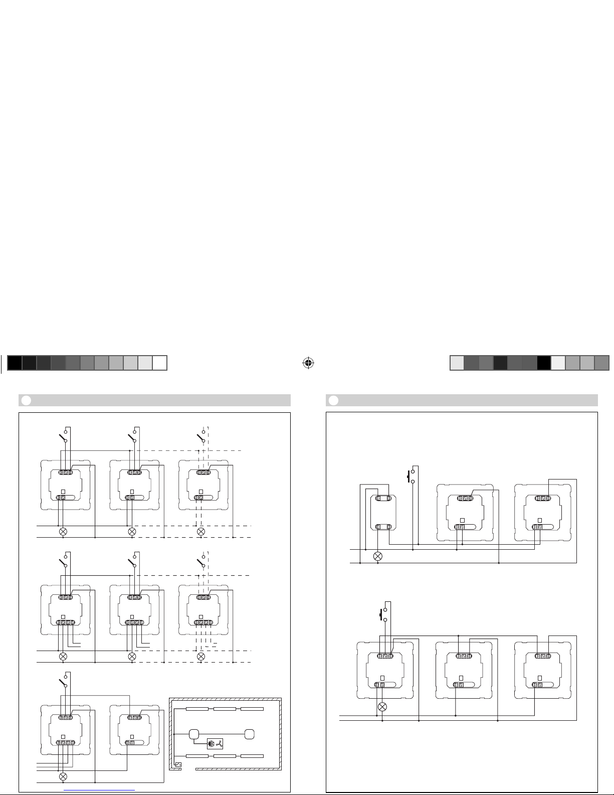
Parallelschaltungen
Zwei Melder an externen
Tr eppenautomat
Altbau / UmbauFremdlicht durch Taster aktiviert.
Kein Dämmerungsmodus, nur
Tagbetrieb möglich.
Melder als Treppenautomat
14.1
14.2
14.3
14.4
Bei Verwendung mehrerer Melder sind diese an dieselbe Phase anzuschließen!
DIM-Melder
14.5
Betriebsstörungen
Licht schaltet nicht ein
Licht schaltet nicht aus
Sensor schaltet trotz
Anwesenheit ab
Sensor schaltet zu spät ab
Sensor schaltet bei frontaler
Gehrichtung zu spät ein
Sensor schaltet trotz Dunkelheit
bei Anwesenheit nicht ein
쐽 keine Anschlussspannung
쐽 Lux-Wert zu niedrig
eingestellt
쐽 keine Bewegungserfassung
쐽 Lux-Wert zu hoch
쐽 Nachlaufzeit läuft ab
쐽 Störende Wärmequellen z.B.:
Heizlüfter, off
ene Türen und
Fenster, Haustiere, Glühbirne/
Halogenstrahler, sich bewegende Objekte
쐽 Nachlaufzeit zu klein
쐽 Lichtschwelle zu niedrig
쐽 Nachlaufzeit zu groß
쐽 Reichweite bei frontaler
Gehrichtung
ist reduziert
쐽 Lux-Wert zu niedrig
gewählt
쐽 Anschlussspannung
überprüfen
쐽 Lux-Wert langsam erhö-
hen bis Licht einschaltet
쐽 Freie Sicht auf den
Sensor herstellen
쐽 Erfassungsbereich
überprüfen
쐽 Lux-Wert niedriger
stellen
쐽 Nachlaufzeit abwarten ggf.
Nachlaufzeit kleiner stellen
쐽 Stationäre Störquellen durch
Aufkleber ausblenden
쐽 Nachlaufzeit erhöhen
쐽 Dämmerungseinstellung
ändern
쐽
Nachlaufzeit verkleinern
쐽 weitere Sensoren
montieren
쐽 Abstand zwischen zwei
Sensoren reduzieren
쐽 Sensor mit Schalter/Taster
deaktiviert ?
쐽 Halbautomatik ?
쐽 Helligkeitsschwelle erhöhen
Störung Ursache Abhilfe
Page 10

Funktionsgarantie
Konformitätserklärung
Dieses Produkt erfüllt die
Niederspannungrichtlinie
2006/95/EG die EMV-Richtlinie
2004/108/EG und die RoHS-
Richtlinie 2002/95/EG.
Dieses Steinel-Produkt ist mit
größter Sorgfalt hergestellt, funktions- und sicherheitsgeprüft
nach geltenden Vorschriften und
anschließend einer Stichproben-
kontrolle unterzogen. Steinel
übernimmt die Garantie für einwandfreie Beschaffenheit und
Funktion.
Die
Garantiefrist beträgt 36 Mo-
nate und beginnt mit dem Tag
des Verkaufs an den Verbr aucher.
Wir beseitigen Mängel, die auf
Material- oder Fabrikationsfehlern beruhen, die Garantieleistung erfolg
t durch Instandset-
zung oder Austausch mangel-
hafter Teile nach unserer Wahl.
Eine Garantieleistung entfällt für
Schäden an Verschleißteilen so-
wie für Schäden und Mängel, die
durch unsachgemäße Behand
-
lung oder Wartung auftreten.
Weitergehende Folgeschäden an
fremden Gegenständen sind ausgeschlossen.
Die Garantie wird nur gewährt,
wenn das unzerlegte Gerät mit
kurzer Fehlerbeschreibung,
Kassenbon oder Rechnung (Kaufdatum und Händlerstempel), gut
verpackt, an die zutreffende Servicestation eingesandt wird.
Reparaturservice:
Nach Ablauf der Garantiezeit
oder Mäng
eln ohne Garantiean-
spruch repariert unser Werkser-
vice. Bitte das Produkt gut ver-
packt an die nächste Servicestati-
on senden.
쐽 Disconnect the power supply
before attempting any work
on the sensor!
쐽 During installation, the elec-
tric power cable to be con-
nected must be dead. There-
fore, sw
itch 'OFF' the power
first and use a voltage tester
to make sure the wiring is off
circuit.
쐽 Installing the sensor involves
work on the mains power
supply. This work mus
t there-
fore be carried out professionally in accordance with
the applicable national wiring regulations and electrical
operating conditions (VDE
0100).
System components
Load module
Sensor module
Sensor base
Dip switches
(1) Normal/test mode
(2) Semi-/fully automatic
mode
(3) Button/switch
(4) 'ON' / 'ON'-'OFF' button
(5) DIM option
Constant lighting control
Twilight setting
Time setting
Switching output 1
HVAC stay-'ON' time
Switching output 2
HVAC switch-'ON' delay
Switching output 2
Reach setting
Clamp
ing-type ceiling
adapter, optional
Surface-mounting adapter
IP 54, optional
Locking mechanism
Assembly/Installation
Parallel-connected
configurations
Stay-'ON
' time
Orientation light
DIM option
Assembly/Installation (see chart on page 2)
The sensor is only intended for
concealed, indoor installation in
ceilings (apart from the COM 1
AP - surface-mounted - option).
A clamping-type ceiling adapter
or sur
face-mounting adapter is
not included.
Sensor and load module come
ready assembled and must be
plugged together after fitting
the load module and setting the
potentiometers/dip switches.
(
Accessories:
Clamping-type ceiling adapter,
EAN no.: 4007841 000370
Surface-mounting adapter,
EAN no.: 4007841 000363
Guard cage,
EAN no.: 4007841 003036
Service remote control,
EAN no.: 4007841
000387
User remote control,
EAN no.: 4007841 003012
Operating instructions
GB
Dear Customer,
Congratulation on purchasing
your new STEINEL presence detector and thank you for the
confidence you have shown in
us. You have chosen a high-quality product that ha
s been manufactured, tested and packed with
the greatest care.
Please familiarise yourself with
these instructions before attempting to install the presence
detector becaus
e prolonged, re-
liable and trouble-free operation
will only be ensured if it is fitted
and used properly.
We hope your new STEINEL
sensor will bring you lasting
pleasure.
Safety warnings
Page 11

How it works / Basic function
The high-frequency presence
detectors from the Control PRO
range control lighting as well as
heating, ventilation and air-conditioning (COM 2 only), e.g. in offices, WCs,
public buildings or at
home, in relation to ambient
light level and the presence of
persons. Modern, high-frequen-
cy technology guarantees that
movement is detecte
d absolute-
ly anywhere irrespective of radi-
ated temperature. Sensing
movement in two directions, the
DUAL HF sensor is ideal for corridors in hotels, schools and office
buildi
ngs. The presence detec-
tor's switching outputs and
reach are set at the potentiometers and dip switches or by
means of the optional remote
control. Presence Control has
a low intri
nsic power consump-
tion.
Presence Control PRO
HF 360 COM 1 / COM 1 AP
DUAL HF COM 1 / COM 1 AP
1 switching output operating
in relation to brightness setting
and presence of persons.
Settings:
- Brightness setting
- Stay-'ON' time, pulse mode,
IQ mode
Presence Control PRO
HF 360 COM 2
1 switching output, such as
COM 1. Plus a 2nd switching
output for HVAC (heating /
ventilation / air conditioning)
governed by presence.
Settings:
- Stay-'ON' time
- Switch-'ON' del
ay
- Room surveillance
Presence Control PRO
HF 360 DIM
DUAL HF DIM
1 switching output operating
in relation to brightness setting
and presence of persons.
Settings:
- Brightness setting
- Stay-'ON' time, IQ mode
- Orientation light
-
Constant lighting control
Detection zone
Electrical installation/Automatic mode
In selecting the wiring leads, it is
important to meet the wiring
regulations laid down in VDE 0100
(see Safety warnings on page 19).
The following applies to wiring
presence detectors
: According to
section 6 of VDE 0100 520, a multi-
ple-core lead containing both the
mains voltage leads and the con-
trol leads (e.g. NYM 5 x 1.52) may
be used for wiring between the
sens
or and electronic ballast. The
mains connection lead must be no
greater than 10 mm in diameter.
The clamping range of the mains
terminal is designed for a maximum of 2 x
1.5 mm2 or 1 x 2.5 mm2.
PSN
LL'B1B2
L
N
B1
B2
P
L
N
B1
B2
max. 1 A
COM2
PSN
LL'
L
N
P
L
N
COM1
PSN
LL'
L
N
L
N
1-10V
1-10V
+
–
max. 100 mA
DIM
DIMCOM 1 COM 2
L
N
P
L
N
PSNLL' PN
COM 1 AP
The reach of the HF 360 is electronically adjustable.
1 or 2 detection directions can be masked out for
adjustment to the room situation. An angle of coverage of 36
0° provides a max. reach of 8 m.
The DUAL HF sensor has 2 special HF sensors that
detect movement from the ceiling in both directions. Controlled electronically,
reach is infinitely
variable in both directions from 3 x 3 m – 10 x 3 m.
HF 360 mounting height 2.8 m PC PRO DUAL HF mounting height 2.8 m for all
Page 12
Technical Specifications
DIP 4
In the 'ON'-'OFF' setting, the light
can be switched 'ON' and 'OFF'
manually at any time (except in
pulse mode: no manual 'OFF').
In the 'ON' setting, light can no
longer be switched 'OFF' manu-
ally. The stay-'ON' time starts
from the beginning again each
time the button is pressed.
'ON'/'ON'-'OFF' button
DIP 1
Functions – Settings by DIP switch
Test mode has priority over all
other settings on the presence
detector and serves the purpose
of checking for proper working
order as well for testing the detection zone. Irre
spective of am-
bient light level, the presence
detector activates the light to
stay 'ON' for approx. 8 sec. in re-
sponse to movement in the
room (blue LED
flashes when
movement is detected). All user-
selected potentiometer settings
apply in normal mode. The presence detector can also be set by
means of the blue LED without
any load connecte
d.
Normal mode / Test mode (NORM / TEST)
DIP 2
The light automatically switches
'ON' and 'OFF' in relation to
brightness when someone is
present. Light can be switched
'ON' and 'OFF manually at any
time. This temporarily interrupts
the automatic sw
itching func-
tion. Irrespective of the settings
selected, light stays 'ON' for 4
hours after manually pressing
the button twice or switches
'OFF' after manually pressing the
b
utton once. Pressing the button before the 4 hours elapse
returns the Presence Control IR
Quattro to the normal operating
mode.
Semi-automatic mode (MAN) / fully automatic mode (AUTO)
Fully automatic mode: (AUTO)
Semi-automatic mode: (MAN)
The light now only switches
'OFF' automati
cally. Light is
switched 'ON' manually. Light
must be requested using the
button and stays 'ON' for the
time set at the potentiometer.
(pressing twice switches 'ON' for
4 hour
s).
DIP 3
Tells the sensor how to interpret
the incoming signal. Assigning
external buttons/switches allows
you to operate the detector as a
semi-automatic unit and over-
ride it manually at
any time.
■ Operation either by button
or switch
■ Several buttons possible
on one control input
■ Only use illuminated push-
button with neutral conductor
connected
■ Cable length between sensor
and switch < 50 m
Button/switch
COM 1 + COM 2
DIP 5
Provides a constant level of
brightness. Detector measures
the prevailing level of daylight
and activates sufficient artificial
light to achieve the required le
v-
el of brightness. As daylight
changes, the switched-in artificial lighting component is adjusted accordingly. In addition to
the daylight component, artific
ial
light is also switched 'ON' and
'OFF' in relation to whether or
not persons are present.
Constant light 'ON'/'OFF'
DIM
Dimensions
(w x h x d)
HF 360
120 x 120 x 56 mm
Dual HF
120 x 120 x 76 mm
Supply voltage 230 – 240 V, 50 Hz / 60 Hz
Capacity, switching output 1
(COM 1/COM 2)
Relay 230 V
Resistive load 2000 W max. (
cos ϕ = 1)
1000 VA max. (cos ϕ = 0,5)
Electronic ballast:
(COM 1/COM 1 AP/
COM 2/DIM)
Max. 'ON' current 800 A/200 μs
30 x (1 x 18 W), 25 x (2 x 18 W )
25 x (1 x 36 W), 15 x (2 x 36 W )
20 x (1 x 58 W), 10 x (2 x 58 W )
Pay attention to specific 'ON' currents of electronic ballasts!
A relay or contactor must be provided on line side for high
er switching
capacities.
Capacity, switching output 2
(COM 2 only) (HF 360 only)
Presence
230 W max. / 230 V
1A max. (cos ϕ = 1) for HVAC (heating/ventilation/air-conditioning)
Application indoors
Moun
ting height
(mounted to ceiling)
2.5 m – 3.5 m ceiling height
Detection angle HF 360
360° with 140° aperture angle
also through glass, wood and
stud walls. 1 or 2 detection directions can be ma
sked out for ad-
justment to the room situation.
Dual HF
see diagrams on p. 20
also through glass, wood and stud
walls
Reach HF 360
8 m max. all round,
electronically and infinitely
variabl
e
Dual HF
10 x 3 m max. in each direction,
electronically and infinitely
adjustable
Switching output 1
Time setting
30 sec. – 30 min., pulse mode (approx. 2 sec.)
IQ mode (automatic adjustment to use profi
le)
Switching output 2
Time setting
COM2 only for HVAC
0 sec. – 10 min. switch-'ON' delay
1 min. – 2 h stay-'ON' time
Automatic room surveillance
DIM:
Time setting
30 sec. - 30 min.
IQ mode (automatic adjustment to use profile)
Control output
1 – 10 V / max. of 50 electronic ballasts, max. of 100 mA
Sensor system High-frequenc y 5.8 GHz, transmission power < 1mW
Function setting by
DIP switches
DIP 1 Normal / test
mode
DIP 2 Semi- / fully automatic mode
DIP 3 Button / switch mode
DIP 4 'ON' button / 'ON'-'OFF' button
DIP 5 Constant-lighting control 'ON'-'OFF' (DIM)
Parallel connections Master/slave
Master/master
User-friendly setting capability Tea ch-in (with optional remote control RC3)
Light-level setting 10 – 1000 lux, ∞ / daylight
DIM 100 – 1000 lux
IP rating IP 20 (IP 54 with surface-mounted box)
Safety class II
Tem perature ra
nge0° to +40° C
Housing UV-resistant, paintable
Page 13

Functions – Settings by potentiometer
Examples of use Brightness settings
Night-time modemin
Corridors, foyers 1
Stairs, escalators, moving walkways 2
Washrooms, toilets, switchrooms, canteens 3
Sales oor, kindergartens, nursery school rooms,
sports halls
4
Work env
ironments: O ces, conference and mee-
ting rooms, precision assembly activities, kitchens
5
Working areas requiring good light:
Laboratory, technical drawing, precision work
>=6
Daylight mod
e max
Stay-'ON' time for switching
output 1
Setting 30 sec. – 30 min.
The chosen stay-'ON' time is infinitely variable from a minimum
of approx. 30 sec. to a maximum
of 30 min.
Light is calibrated after
3 min. When the threshold is
exceeded, the sensor switches
'OFF' after the stay-'ON' time
expires.
Time setting
If the dial is set to (fully anticlockwise), the unit is in pulse
mode, i.e. the output is switched
'ON' for approx. 2 sec. (e.g. for stair-
well lighting timer). Afterwards,
the s
ensor does not respond to
movement for approx. 8 sec. Day
mode is the only mode possible
here because of dazzle by light
from external sources.
Turned fully clockwis
e: The stay-
'ON' time is self-learning and ad-
justs dynamically to user behav-
iour. The optimum time cycle is determined by means of a learning
algorithm. The shortest time is
2
min., the longest 20 min.
Pulse mode (except DIM)
IQ mode
The chosen response threshold
can be infinitely varied from
approx. 10 – 1000 lux.
Control dial turned fully clockwise:
MAX daylight mode
Control dial turned fully anti-clock-
wise: MIN ni
ght-time operation
Depending on the site of installation, the setting may need to
be corrected by 1-2 marks on
the scale.
Twilight setting
Potentiometer
Potentiometer
COM 1 + COM 2
Note: Depending on the site of installation, the setting may need to be corrected by 1 – 2 marks on the scale.
Setting 1 sec. – 2 hr.
• Turned fully clockwise: max
• Turned fully anti-clockwise: min
• Setting 0 sec. – 10 min.
• Turned fully clockwise:
Room surveillance
• Turned fully anti-clockwise:
0 sec. ('OFF')
Turning the potentiometer to the
"Surveillance" setting reduces the
sensitivity of the "Presence"
switching output. Th
e contact only
closes on detecting a pronounced
movement, signalising with a high
degree of certainty that persons
are present.
The stay-'ON- time remains active.
The swit
ch-'ON' delay is inactivat-
ed.
Switch-'ON' delay for switching output 2 HVAC
Reach adjustment
COM 2
Potentiometer
Potentiometer
Provides basic illumination for the
selected stay-'ON' time when ambi-
ent light falls below the selected
brightness threshold that is set. This
can be dimmed to 10% o
f maximum light intensity. As soon as a
person enters the scene, the detec-
tor switches either to 100% light
intensity (constant-lighting control-
ler 'OFF') or adjusts to
the preselect-
ed brightness level (constant-lighting controller 'ON'). When no movement is being detected, the detector dims back to basic brightness
after the s
tay-'ON' time expires. This
is switched 'OFF' when stay-'ON'
time (1 min. – 30 min.) has expired
or the daylight component is suffi-
cient to exceed the selected level o
f
brightness. In the 'ON' setting, the
detector switches basic brightness
'ON' and 'OFF' as soon as the level
of light falls below the brightness
threshold.
Basic brightness (DIM option)
Potentiometer
Stay-'ON' time for switching output 2 HVAC
The reach required (response
threshold) is infinitely variable.
HF 360
1 m min. – 8 m max.
DUAL HF
min. 3 x 3 m – 10 x 3 m in
each direction
Turned fully a
nticlockwise
(factory setting) = minimum reach
Turned fully clockwise
(factory setting) = maximum reach
Potentiometer
Page 14

The master/slave configuration
permits detection of movement in
large-type rooms or spaces (load
connected = master, no load =
slave). The level of brightness pre-
vailing in the
room is only evaluat-
ed at the master. The slaves report
movements detected to the mas-
ter. Lighting or HVAC is switched
'ON' and 'OFF' by the master only.
Master/slave
A parallel-connected configuration
also permits the use of several
masters. In this case, each master
operates the lighting group in
accordance with the level of
brightness
it measures. Delay
times and brightness thresholds
are selected at each master as required. The switched load is spread
among the individual masters.
Presence is still detected c
ollectively by all detectors. The presence output can be picked off
from any master.
Master/master
Remote control
Using the remote control (optional), functions can be conveniently
activated from the floor.
Note: The pulse mode cannot be
overridden by the remote control.
Switch pulse mode 'OFF' manually
.
Presence Control remote control
unit: EAN no.: 4007841 000387
Parallel-connected configurations
Two detectors linked with an
external stairwell lighting
timer
Old building / building moderni-
sation
External light source activated by
button. No twilight mode, day
mode
only.
Detector as stairwell lighting
timer
14.1
14.2
14.3
14.4
When using several detectors, they must be connected to the same phase!
DIM detector
14.5
Troubleshooting
Light does not switch 'ON'
Light does not switch 'OFF'
Sensor switches 'OFF' in spite of
persons being present
Sensor does not switch 'OFF'
quickly enough
Sensor does not switch 'ON'
quickly enough when approached
from the
front
Sensor does not switch 'ON' when
persons are present in spite of it
being dark
쐽 No supply voltage
쐽 Lux setting too low
쐽 No motion detection
쐽 Lux setting too high
쐽 Stay-'ON' time running o
ut
쐽 Interference from sources of
heat, e.g.: fan heater, open
doors and windows, pets,
light bulb/halogen floodlight,
moving objects
쐽 Stay-'ON' time too short
쐽 Light-
level threshold too low
쐽 Stay-'ON' time too long
쐽 Reach is reduced when
approached from the front
쐽 Lux setting too low
쐽 Check supply voltage
쐽 Slowly increase lux setting
until light
switches 'ON'
쐽 Ensure unobstructed sensor
vision
쐽 Check detection zone
쐽 Reduce lux setting
쐽 Wait until stay-'ON' time
elapses; reduce stay-'ON'
time if necessary
쐽 Use stickers to
mask out
stationary sources of
interference
쐽 Increase stay-'ON' time
쐽 Change light threshold
쐽 Reduce stay-'ON' time
쐽 Install additional sensors
쐽 Reduce distance bet
ween
two sensors
쐽 Sensor deactivated by
switch/button?
쐽 Semi-automatic mode?
쐽 Increase light-level threshold
Malfunction Cause Remedy
Page 15

Functional Warranty
Declaration of Conformity
This product complies with Low
Voltage Directive 2006/95/EC,
EMC Directive 2004/108/EC and
RoHS Directive 2002/95/EC.
This Steinel product has been
manufactured with utmost care,
tested for proper operatio
n and
safety and then subjected to random sample inspection. Steinel
guarantees that it is in perfect
condition and proper working
order.
The warranty period is 36 months
and starts on the date of sale to
the consumer. We will remedy
defects caused by material flaws
or manufacturing faults. The warranty will be met by repair or re-
placement of t
he defective parts
at our own discretion. The war-
ranty shall not cover damage to
wear parts, damage or defects
caused by improper treatment or
maintenance. Further co
nse-
quential damage to other ob-
jects is excluded.
Claims under the warranty will
only be accepted if the product is
sent fully assembled and well
packed complete with a brief de-
scri
ption of the fault as well as a
receipt or invoice (date of purchase and dealer's stamp) to the
appropriate Service Centre.
Repair service:
Our Customer Servic
e Department will repair faults not covered by warranty or after the
warranty period. Please send the
product well packed to your
nearest Service Centre.
 Loading...