

STEINEL LuxMaster BLS, LuxMaster Series, LuxMaster BLS D, LuxMaster BLS T, LuxMaster BLS DF Operating Instructions Manual
Page 1
STEINEL-Schnell-Service
D
Dieselstraße 80-84 · 33442 Herzebrock-Clarholz
Tel: +49/5245/448-188 · Fax:+49/5245/448-197 · www.steinel.de
I. MÜLLER
A
Peter-Paul-Str. 15 · A-2201 Gerasdorf bei Wien
Tel.: +43/2246/2146 · Fax: +43/2246/25466 · www.imueller.at
PUAG AG
Oberebenestrasse 51 · CH-5620 Bremgarten
Tel.: +41/56/6488888 · Fax: +41/56/6488880 · www.puag.ch
STEINEL U.K. LTD.
37, Manasty Road · Orton Southgate · GB-Peterborough PE2 6UP
Tel.: +44/1733/238-265 · Fax: +44/1733/238-270
www.steineluk.com
STC SOCKET TOOL COMPANY Limited
8, Queen Street, Smithfield · IRL-Dublin 7
Tel.: +353/1/8725433 · Fax: +353/1/8725195
[email protected]
DUVAUCHEL S.A.
F
ACTICENTRE - CTR 2
Rue des Famards - Bat. M - Lot 3 · F-59818 Lesquin Cedex
Tél.: +33/3/20 3034 00 · Fax: +33/3/20 3034 20
www.duvauchel.com
VAN SPIJK AGENTUREN BV
Postbus 2 · NL-5688 ZH Oirschot
De Scheper 260 · NL-5688 HP Oirschot
Tel.: +31/499/571810 · Fax: +31/499/575795
www.vsa-hegema.nl
VSA handel Bvba
B
Fabriekstraat 145 · B-3900 Overpelt
Tel.: +32/11/660720 · Fax: +32/11/660729 ·www.vsahandel.be
A. R. Tech.
L
19, Rue Eugène Ruppert, Cloche D’Or · BP 1044
L-1010 Luxembourg
Tel.: +352/49/3333 · Fax: +352/40/2634 · www.artech.lu
THOELKE DISTRIBUZIONE S.N.C.
I
Via Adamello 2/4 · I-22070 Locate Varesino (Como)
Tel.: +39/331/836911 · Fax: +39/331/836913 · www.thoelke.it
SAET-94 S.L.
E
C/ Trepadella, n° 10 · Pol. Ind. Castellbisbal Sud
E-08755 Castellbisbal (Barcelona)
Tel.: +34/93/772 28 49 · Fax: +34/93/772 01 80 · www.saet94.com
P
Pronodis-Soluções
Tecnológicas, Lda · Rua do Caseiro no 87 A/B Vilar
P-3810-078 Aveiro
Tel.: +351/234/484031 · Fax: +351/234/484033 ·
KARL H STRÖM AB
S
Verktygsvägen 4 · S-55302 Jönköping
Tel.: +46/36/31 42 40 · Fax: +46/36/31 42 49 · www.khs.se
BROMMANN ApS
Ellegaardvej 18 · DK-6400 Sønderborg
Tel.: +45/7442 8862 · Fax: +45/7443 43 60 · www.brommann.dk
Oy Hedtec Ab
Hedengren yhtiö · Lauttasaarentie 50 · FIN-00200 Helsinki
Tel.: +358/9/682881 · Fax: +358/9/673813 · www.hedtec.fi/valaistus
N
Vilan AS
Tvetenveien 30 B · N-0666 Oslo
Tel.: +47/22725000 · Fax: +47/22725001 · www.vilan.no
PANOS Lingonis + Sons O. E.
Aristofanous 8 Str. · GR-10554 Athens
Tel.: +30/210/3212021 · Fax: +30/210/3218630
[email protected]
www.
pronodis.pt
EGE SENSÖRLÜ AYDINLATMA ‹TH.
‹HR. T‹C. VE PAZ. LTD. fiT‹.
GERSAN SAN. S‹TES‹ 659.
SOKAK · NO:510 · BATIKENT/ANKARA
Tel.: +90/312/2571233 ·Fax: +90/312/2556041
www.egeaydinlatma.com
ATERSAN ‹TH. T‹C. ve SAN. KOLL. ST‹
Add. Tersane Caddesi Galata Hirdavatcilar Carsisi No: 45
Karakoy / ‹stanbul – TURKEY
Tel.: +90/212/2920664 Pbx. ·Fax: +90/212/2920665
www.atersan.com
ELNAS s.r.o.
Oblekovice 394 · CZ-67181 Znojmo
Tel.: +420/515/220126 · Fax: +420/515/244347
www.elnas.cz
LANGE ŁUKASZUK Sp.j.
Byków 25a · PL-55-095 Mirków
Tel.: +48/71/3 98 08 861 · Fax: +48/71/3 98 19
www.langelukaszuk.pl
H
DINOCOOP Kft
Radvány u. 24 · H-1118 Budapest
Tel.: 36/1/3193064 · Fax: +36/1/3193066
www.dinocoop.hu
KVARCAS
Neries krantine 32 · LT-48463, Kaunas
Tel.: +370/37/408030 · Fax: +370/37/408031 ·
FORTRONIC AS
Teguri 45c · EST 50113 Tartu
Tel.: +372/7/475208 · Fax: +372/7/367229 ·
LOG Zabnica D.O.O.
Podjetje Za Trgovino · Srednje Bitnje 70
SLO-4209 Zabnica
Tel.: +386/42/312000 · Fax: +386/42/312331 ·
Neco s.r.o.
Ruzová ul. 111 · SK-01901 Ilava
Tel.: +421/42/4 44 14 55 · Fax: +421/42/4 44 14 56
www.neco.sk
STEINEL Trading s.r.l.
Str. Lunga 123 · RO-507055 Cristian-Brasov
Tel.: +40/2 68/25 74 00 · Fax: +40/2 68/25 76 00
www.steinel.ro
Daljinsko Upravljanje d.o.o.
B. Smetane 10 · HR-10 000 Zagreb
Tel.: +3 85/1/3 88 02 47 · Fax: +3 85/1/3 88 02 47
[email protected]
Ambergs SIA
Brivibas gatve 195-16 · LV-1039 Riga
Tel.: +3 71/7/55 07 40 · Fax: +3 71/7/55 28 50
www.ambergs.lv
IT und R GmbH
Kuibyshev Str. 78 · RUS-620026 Ekaterinburg
Tel.: +7/34 32/24 23 23 · Fax: +7/34 32/61 61 65
[email protected]
SVETILNIKI
Str. Malaya Ordinka, 39 · RUS-113184 Moskau
Tel.: +7/95/2 37 28 58 · Fax: +7/95/2 37 11 82
[email protected]
www.
www.
fortronic.ee
www.
kvarcas.lt
log.si
LuxMaster
6298204 Technische Änderungen vorbehalten.
D
Bedienungsanleitung
GB
Operating instructions
F
Mode d'emploi
NL
Gebruiksaanwijzing
I
Istruzioni per l'uso
E
Instrucciones de uso
S
Bruksanvisning
DK
Brugsanvisning
FIN
Käyttöohje
N
Bruksanvisning
Page 2
1m
360°
1
2
3
4
1m
1m
2m
2m
12 m
12 m
0
GB
Disconnect the power sup-
ply before attempting any
work on the sensor!
During installation, the
electric power cable to be
connected must be voltage-free. Therefore, switch
off the power first and use
a voltage tester to make
sure the wiring is off circuit.
Safety warnings
Installing the sensor in-
volves work on the mains
power supply. This work
must therefore be carried
out professionally in accordance with the applicable
national wiring regulations
and electrical operating
conditions (VDE 0100).
How it works / basic function
The LuxMaster series of infrared sensors control the
lighting, e.g. in offices,
schools or public buildings
depending on persons present
(motion detection) and surrounding brightness. The light
sensor incorporated in the
sensor constantly measures
ambient light level and compares it with the brightness
setting adjusted on the sensor
(BLS / BLS T 20 – 1300 lux
and BLS D/BLS DF 100 – 1300
lux). If the surrounding brightness is sufficient, the lighting
is not switched ON. If the surrounding brightness is below
The signal provided on the
1–10 V control output is a
functional extra-low voltage and not a safety extralow voltage (SELV). Consequently, appropriately insulated leads are to be used
for wiring.
the adjusted brightness setting, a movement in the room
causes the light to be
switched ON. A choice of 4
versions is available:
Detection zone
BLS - switching ON and OFF
of the light independently of
occupancy and daylight.
Light only with presence in the
room. Once the surrouding
brightness reaches the set theoretical value, the lighting is automatically switched OFF again.
BLS T - semi-automatic occupancy detector. ON manually. OFF automatically, when
light is no longer needed.
The user switches the light ON
manually (classroom function)
using a switch to be incorporated (break-contact button). By
briefly pressing and immediately releasing the button / switch
(approx. 0.2 – 1 sec.), the voltage supply is briefly interrupted
and the BLS T transfers to standard sensor mode. If the room
is left without operating the button again, the light goes out
once the set time value has
elapsed or once the set twilight
value is exceeded. If the button
is briefly pressed again on leaving the room (approx. 0.2 –
1 sec.), the light switches OFF
12
automatically and does not
switch ON again automatically.
If the button is pressed for
longer (> 2 sec.), the BLS is
completely free of voltage, performs a self-test on release and
the lighting goes ON for the set
time.
BLS D – dimming of the lighting depending on presence
and daylight
The sensor simultaneously detects the difference between the
set theoretical value and the
surrounding brightness and
raises the brightness of the
lighting until the set theoretical
value is achieved in the room.
Changes in the surrounding
brightness are constantly detected by the sensor and are
adjusted such that with occupancy, a constant brightness
prevails in the room.
BLS DF – dimming of the
lighting depending on occupancy and daylight – optionally with remote control
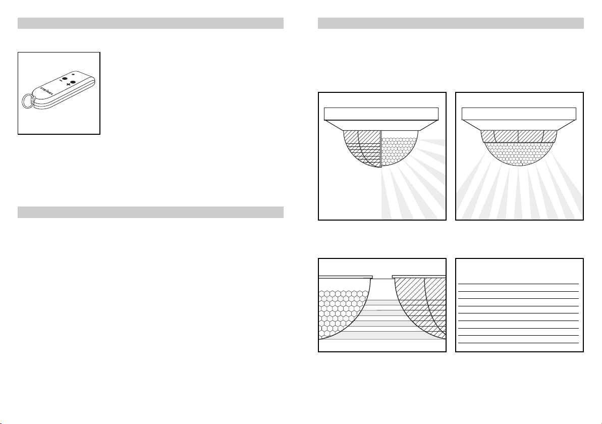
With this sensor, it is also possible to alter the light level (brightness setting) with an infrared remote control. The lighting can
therefore be conveniently
dimmed to the desired light level, for example during slide
shows or when using a projector.
The modifications in the light
level made with the remote
control can be conveniently reset to the light level adjusted on
the sensor using the reset function (simultaneous pressing of
both buttons (+) and (–)) .
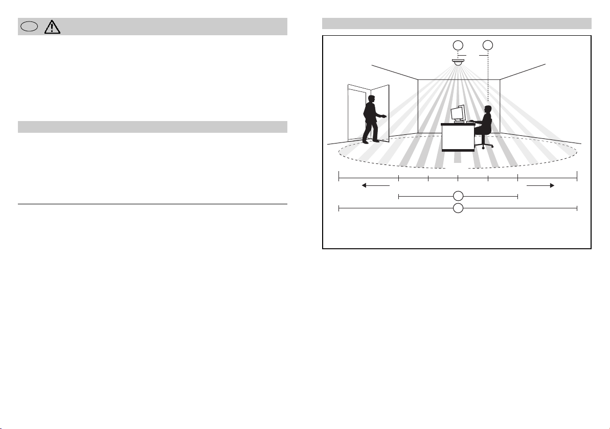
Sensor
Seated
The reliable occupancy de-
tection of the BLS sensors
considerably depends on the
number, condition and arrangement of the lens segments.
With three pyro sensors and a
detection zone of 360°, consisting of 11 levels with 1320
switching zones, even the
smallest movements in the
close range (2 m radius
around the sensor) and walking
movements in the long-dis-
tance range (up to 12 m) are
recorded. In this manner, even
larger offices can be monitored
with only one sensor.
Close-up range (radius 2 m)
Long-distance range (radius 12 m)
If specific areas are to be excluded from detection, the detection zone can be deliberately adjusted by applying shrouds
(see Reach setting section).
Optimum installation site:
The sensor is only suitable for
ceiling installation in rooms. It
should always be installed so
that seated individuals see the
sensor at a distance of approx.
1 m in front of them (see Fig.).
Reliability of detection in the
close range is greatest in this
position. Walking individuals
are still detected within the
long-distance range.
13
Page 3
L
L
N
L
L
N
+
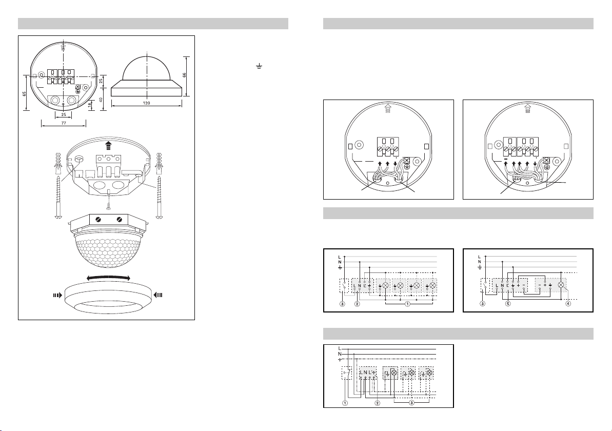
Assembly/Installation
– Neutral conductor N
– Phase L
– Switched phase L
– Earth conductor (protective-
earth conductor)
– Control output +
– Control output –
– (only BLS D and BLS DF)
For surface wiring, the groove
on the decorative ring is to be
pierced and the cable is to be
introduced from the side.
16. Push-fit the sensor hous-
ing on to the mounting
plate from the side
(against the direction of
the arrow)
17. Screw in the locking
screw
18. Perform a function test
and adjust the detection
zone (see pages 16 and 19).
19. Adjust the switch-off delay
and brightness setting on
the front of the enclosure
(control dial) (see Functions p. 17, Adjustments
section).
10. Apply the decorative ring
(clip in place). (Shrouds
are fixed with the decorative ring).
.
.
Electrical installation/automatic mode
In selecting the wiring leads, the
wiring regulations according to
VDE 0100 must be complied
with (see safety warnings on
page 12). The following applies
for wiring of the BLS D and
BLS DF: According to VDE 0100
BLS / BLS T
Mains lead
e.g. NYM 3 x 1.5
2
520 sect. 6, a multiple lead may
be used for wiring between the
sensor and electronic ballast,
containing both the mains voltage leads and the control leads
(1–10 V) (e.g. NYM 5 x 1.5
2
).
BLS D / BLS DF
Light
Mains lead
Wiring example/manual switch-off
If it is to be possible to deliberately switch off the auto-
BLS BLS D / BLS DF
matic function of the sensor
manually, a conventional
The mains supply lead must
be no greater than 10 mm in
diameter.
The clamping range of the
mains terminal is designed for
a maximum of 2 x 1.5 mm
2
1 x 2.5 mm
.
(e.g. NYM 5 x 1.5
switch is to be positioned
upstream from the sensor.
2
or
Light with
dimming
electonic ballast
2
)
Installation procedure
1. Pull off the decorative
ring by pressing lightly on
the sides and simultaneously turning downwards.
2. Unscrew the
screw.
3. Pull the sensor enclosure
in the direction of the
arrow
locking
off the mounting plate
.
14
4. Install the mounting plate
under the ceiling using the
enclosed screws and dowels.
5. Perform wiring (see Electrical installation).
1) Light group, 2) BLS, 3) External switch
4) Light with dimming electronic ballast, 5) BLS D / BLS DF
Wiring example semi-automated BLS T
1) Break-contact button, 2) BLS T, 3) Load, lighting
15
Page 4
Technical specifications
Power supply: 230 V, 50 Hz
Switching capacity: max. 2000 W (resistive load, e.. g. filament bulb)*
Detection zone: 360° horizontally, 180° vertically
Recommended
installation height: 2.5–3 m (ceiling installation)
Max. reach: High-resolution close-up range: 4 x 4 m (persons seated)
Switching threshold or BLS / BLS T: 20–1300 lux, daylight operation
constant light level: BLS D / BLS DF: 100 –1300 lux, daylight operation
Switch-off delay: 4 – 30 min., 2h
Enclosure: IP 20
Ambient temperature: –15° to 50° C
Control signal: 1 – 10 V (max. 50 electronic ballasts)
(only BLS D + BLS DF)
Reach (IR rem. control): 4 m (BLS DF only)
VDE certified
*
max. 1000 W (low-voltage halogen)
max. 1000 W (fluorescent lamps with capacitive ballasts, cos ϕ = 0,5)*
max. number of electronic ballasts:
16 x (1 x 36 W) or 12 x (2 x 36 W) or
12 x (1 x 58 W) or 8 x (2 x 58 W)
A relay or contactor must be provided on the line side for higher
switching capacity
reliable long-distance range: 24 x 24 m (persons walking)
Function test / test mode
The test mode is suitable for
verifying operational status
and for specifically adjusting
the detection zone (also see
Reach setting section).
BLS / BLS T
In order to activate test
mode, the control for the light
threshold is to be turned to
the "Test" position. In test
mode, the sensor switches on
the lighting with an overshoot
time of 5 seconds, regardless
of the surrounding brightness.
Note: When the sensor
switches the lighting off, a
short waiting time of approx.
4 sec. must be observed before the sensor can react to
movement again.
BLS D / BLS DF
In order to activate test mode,
the control for the time setting
is to be turned to the "Test"
position. During test mode, the
light control (dimming) directly
follows all changes in brightness (e. g. hold a hand in front
of the sensor lens). The correctness of the wiring can be rapidly checked in this manner.
If the sensor does not dim the
lighting in accordance with the
16
changes in brightness, the
wiring has not been performed
correctly.
When test mode is quitted, the
dimming behaviour of the sensor is optimally readjusted to
human perception.
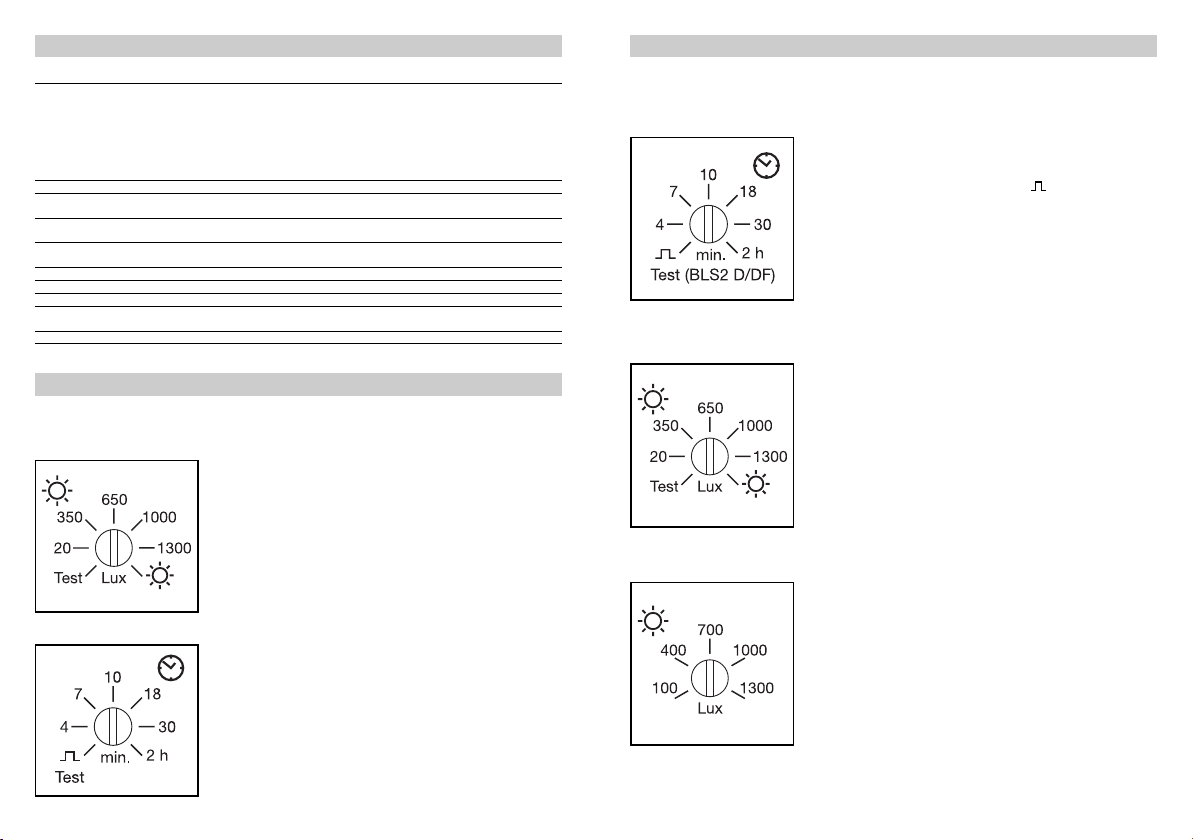
Functions
One potentiometer is provided
in order to determine the
brightness setting (lux value) in
addition to the switch-off delay
BLS / BLS T / BLS D / BLS DF
Adjusting the light level
Using the switch-off delay
(4–15 minutes), the period is
determined during which the
light remains switched ON after
recording the last movement.
With each further detection of
movement, the set overshoot
time begins again until motion
is no longer detected or the
surrounding brightness reaches
the adjusted brightness setting.
BLS / BLS T
Adjusting the brightness setting
The brightness setting to be
set on the sensor (20–1300 lux)
determines the daylight-dependent switching behaviour
of the sensor. On operation of
the control, the sensor switches the lighting OFF in any
case. On completion of adjustment, the following applies:
BLS D / BLS DF
Adjusting the brightness setting
Thebrightness setting to be
set on the sensor (100–1300
lux) determines the total light
level in the room. If the surrounding brightness lies below
the set theoretical value on
motion detection, the light
sensor detects the difference
and dims the lighting until the
desired theoretical value is
achieved. Changes in the
amount of daylight are constantly detected by the light
(time setting) respectively.
Only BLS / BLS T:
Pulse mode: If the controller is
set to “ ”, the device is in
pulse mode, i.e. the output is
switched ON for approx. 2 sec.
(e.g. for an staircase lighting
timer). Afterwards, the sensor
does not react to movement for
approx. 8 sec.
if the amount of daylight is
below the set brightness setting, the lighting is switched
ON; if the amount of daylight
is above the brightness setting, the lighting is switched
OFF – even in case of movement within the detection
zone.
sensor and are adjusted such
that with occupancy, a constant brightness prevails in the
room.
Hint: The brightness setting is
best adjusted in test mode
(control for switch-off delay
set to "Test"), since the light
control (dimming) follows all
changes in brightness in this
case.
17
Page 5
1
2
3
4
5
6
7
8
BLS DIMM
Functions
BLS DF
IR remote control
For the sensor BLS DF the option also exists of adjusting
the desired light level by
means of an infrared remote
control. The last selected setting is respectively maintained
in this case. By constantly
pressing the (–)-button, the
lighting also be switched OFF
completely using the remote
control. By subsequent pressing the (+) button, the desired
level of brightness can be
readjusted.
Reset function
By simultaneously pressing
both buttons (+) and (–), all the
modifications made using the
remote control are reset to the
brightness setting adjusted on
the sensor.
Guideline values for adjusting the lux and time value
Important note:
During adjustment of the
brightness setting, it should
be noted that the measured
The following guideline values may be taken as a basis:
Brightness setting:
Passageways (not working areas): 200 lux
Working areas (offices, training rooms, workshops etc.): 500 lux
Working areas requiring good light:
(technical drawing, laboratories, precise work) 700 – 1000 lux
Switch-off delay:
The switch-off delay can be continuously adjusted according to the use of the respective rooms:
Mainly standing activities (e. g. photocopier room, passageways etc.): 4 min.
Mainly seated activities (desk work by 3–4 individuals): 7 min.
Mainly seated activities (desk work by 1–2 individuals): 10 min.
Seated activities with little movement (reading, EDP, etc.): > 10 min.
If the lighting immediately switches ON again in response to movement in spite of occupancy,
the switch-off delay is to be increased.
18
brightness values of the sensor refer to the installation site
of the sensor under the ceiling
and may therefore not neces-
sarily correspond to the
desired brightness at the
workplace.
Adjustment of the detection zone/reach
The shrouds supplied can be
used for deliberate adjustment
of the detection zone. Using
these, it is possible for example to cleanly separate individ-
Vertical separation =
reduction of the angle of coverage
The shrouds are divided into 8 areas (horizontally). The reach is reduced depending on the
ual workplace areas in an
open-plan office so that only
movements in the area of the
respective desk group are detected. We recommend acti-
Horizontal separation =
reduction of the reach
Shroud
(see drawing)
0 (without cov.) = 12 m = 12 m
1 = 6.5 m = 10 m
2 = 5 m = 9 m
3 = 3.5 m = 8 m
4 = 3 m = 6 m
5 = 2.3 m = 4.5 m
6 = 1.5 m = 3 m
7 = 1 m = 2.2 m
8 < 0.5 m < 1 m
shrouds applied (number of areas).
vating test mode for rapid and
precise adjustment of the detection zone (see page 16).
Reach
(installation
at a height
of 2.5 m)
Reach
(installation
at a height
of 5 m)
19
Page 6
Troubleshooting
Malfunction Cause Remedy
Light does not switch ON No supply voltage
Light does not switch OFF Lux value too high
Sensor switches OFF
in spite of occupancy
Sensor switches OFF
too late
Sensor switches ON too
late when approached
frontally
Sensor switches
too frequently with changing cloud cover
only BLS D, DF:
Sensor does not react to
changes in brightness in
test mode
only BLS DF:
Sensor does not switch ON
with occupancy in spite of
darkness
The light level set with the
hand-held transmitter is no
longer saved
Lux value set too low
No motion detection
Overshoot time running out
Interferring sources of
heat, e.g.: fan heaters,
open doors and windows,
pets
Overshoot time too short Increase overshoot time
Overshoot time too long Reduce overshoot time
Reach is reduced when
approached frontally
Overshoot time set too
short
Control leads (+,–)
not correctly wired
Sensor previously switched
OFF with hand-held transmitter
Lux value selected too low
Settings deleted, since
voltage supply to the sensor cut off
(e.g. by light switch or
power failure)
Check supply voltage
Slowly increase lux value
until light switches ON
Establish a clear view of
the sensor
Check detection zone
Reduce lux value
Wait until overshoot time
elapses; reduce overshoot
time if necessary
Blank off stationary
sources of interference
using shrouds
Install further sensors
Reduce distance between
two sensors
Increase overshoot time
more pleasant switching
behaviour
Replace the control leads
on the sensor or electronic
ballast
Activate sensor by press-
ing the (+) button on the
hand-held transmitter
Increase lux value on the
sensor or by pressing the
(+ ) button on the handheld transmitter
Ensure voltage supply to
the sensor
Declaration of conformity
This product complies with
Low Voltage Directive
06/95/EC, EMC Directive
Functional Warranty
This Steinel product has been
manufactured with utmost
care, tested for proper operation and safety and then subjected to random sample inspection. STEINEL undertakes
the guarantee for perfect condition and function.
04/108/EC and RoHS
Directive 02/95/EC.
The warranty period is 36
months and starts on the date
of sale to the consumer. We
will remedy defects caused by
material flaws or manufacturing faults. The warranty will be
met by repair or replacement
of defective parts at our own
discretion. The warranty shall
not cover damage to wear
parts, damage or defects
caused by improper treatment
or maintenance. Further consequential damage to other
objects is excluded.
Claims under the warranty
shall only be accepted if the
product is sent fully assembled and well packed complete with a brief description of
the fault, a receipt or invoice
(date of purchase and dealer's
stamp) to the appropriate Service Centre.
Repair Service:
Our Customer Service Department will repair faults not covered by warranty or after the
warranty period. Please send
the product well packed to
your nearest Service Centre.
20
21
 Loading...