

Page 1
DE
GB
Information
HF 3360
Page 2
...
DE � � � � � � � 11
GB � � � � � � � 17
Textteil beachten!
Follow written instructions!
2
Page 3
HF3360LiveLink
3
Page 4
45678910
Page 5
Page 6
Page 7
Page 8
Page 9
Page 10
Page 11
DE
!
!
1� Zu diesem Dokument
– Bitte sorgfältig lesen und aufbewahren!
– Urheberrechtlich geschützt.
Nachdruck, auch auszugsweise, nur mit unserer Genehmigung.
– Änderungen, die dem technischen Fortschritt dienen, vorbehalten.
Symbolerklärung
Warnung vor Gefahren!
Verweis auf Textstellen im Dokument�
...
2� Allgemeine Sicherheitshinweise
Vor allen Arbeiten am Sensor die Spannungszufuhr unterbrechen!
• Bei der Montage muss die anzuschließende elektrische Leitung spannungsfrei sein.
Daher als erstes Strom abschalten und Spannungsfreiheit mit einem Spannungsprüfer überprüfen.
• Bei der Installation des Sensors handelt es sich um eine Arbeit an der Netzspannung. Sie muss daher fachgerecht nach den landesüblichen Installationsvorschriften und Anschlussbedingungen durchgeführt werden. (z.B. DE-VDE 0100,
AT-ÖVE-EN 1, CH-SEV 1000)
3� HF3360LiveLink
Bestimmungsgemäßer Gebrauch
– Sensor zur Decken- und Wandmontage im Innenbereich geeignet
Der HF3360LiveLink ist ein aktiver Bewegungsmelder. Er reagiert temperaturunabhängig auf kleinste Bewegungen. Der integrierte HF-Sensor sendet hochfrequente
elektromagnetische Wellen (5,8GHz) aus und empfängt deren Echo. Bei der kleinsten
Bewegung im Erfassungsbereich wird die Echoveränderung vom Sensor wahrgenommen. Ein Microprozessor löst dann den Schaltbefehl "Licht einschalten" aus.
Eine Erfassung durch Türen, Glasscheiben oder dünne Wände ist möglich.
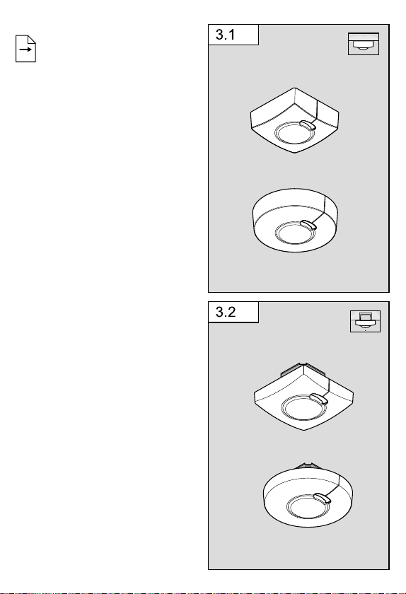
Lieferumfang Aufputzmontage (Abb�3�1)
Lieferumfang Unterputzmontage (Abb�3�2)
DE
11
Page 12

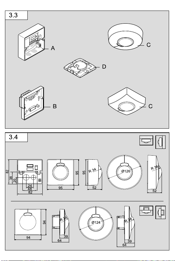
Geräteübersicht (Abb�3�3)
A Lastmodul Zuleitung Aufputz
B Lastmodul Zuleitung Unterputz
C Designblende rund oder eckig
D Sensormodul
Produktmaße
Decken-/Wandmontage Auf- und Unterputz (Abb�3�4)
4� Elektrische Installation
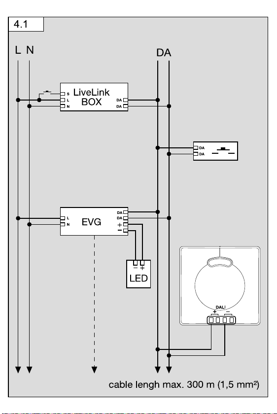
Für die Verdrahtung der Bewegungsmelder gilt: Nach VDE 0100 520 Abschn. 6 darf
für die Verdrahtung zwischen Sensor und LiveLink-Box eine Mehrfachleitungverwendet werden, die sowohl die Netzspannungsleitungen als auch die Steuerleitungen
enthält (z.B. NYM 5 × 1,5). Die maximale Leitungslänge zwischen LiveLink Box und
Sensor darf 300 m (bei 1,5 mm²) nicht überschreiten. Nach der Installation und dem
Einschalten benötigt die LiveLink Box ca. 45 Sekunden um zu starten.
Danach beginnt der Sensor während der Initialisierung im Sekundentakt zu blinken.
Anschlussbeispiel (Abb�4�1)
– Aufputz-Variante
Bei Beschädigung der Dichtgummis müssen die Önungen zur Kabeldurchführung
mit einem Doppelmembranstutzen M16 bzw. M20 (mind. IP54) abgedichtet werden.
5� Montage
• Alle Bauteile auf Beschädigungen prüfen.
• Bei Schäden das Produkt nicht in Betrieb nehmen.
• Geeigneten Montageort unter Berücksichtigung der Reichweite und Bewegungs-
erfassung vornehmen.
Montageschritte
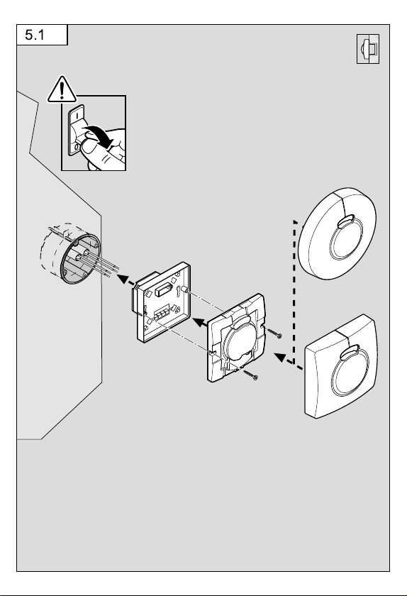
Wandmontage Unterputz-Zuleitung (Abb�5�1)
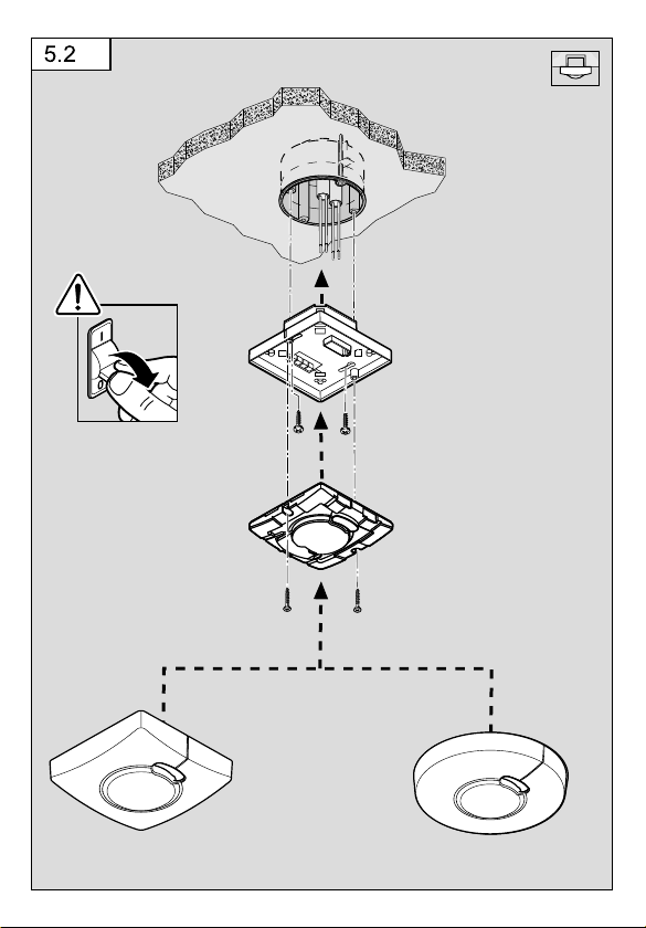
Deckenmontage Unterputz-Zuleitung (Abb�5�2)
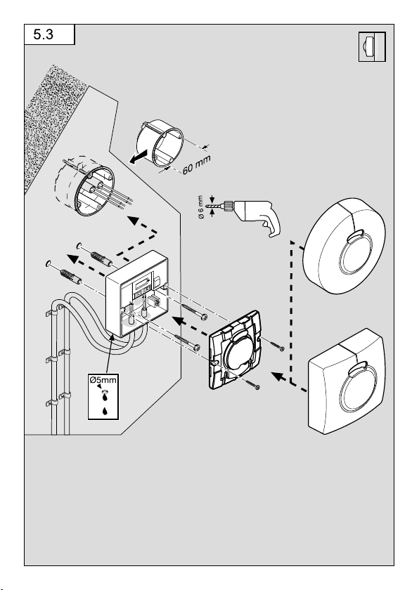
Wandmontage Aufputz-Zuleitung (Abb�5�3)
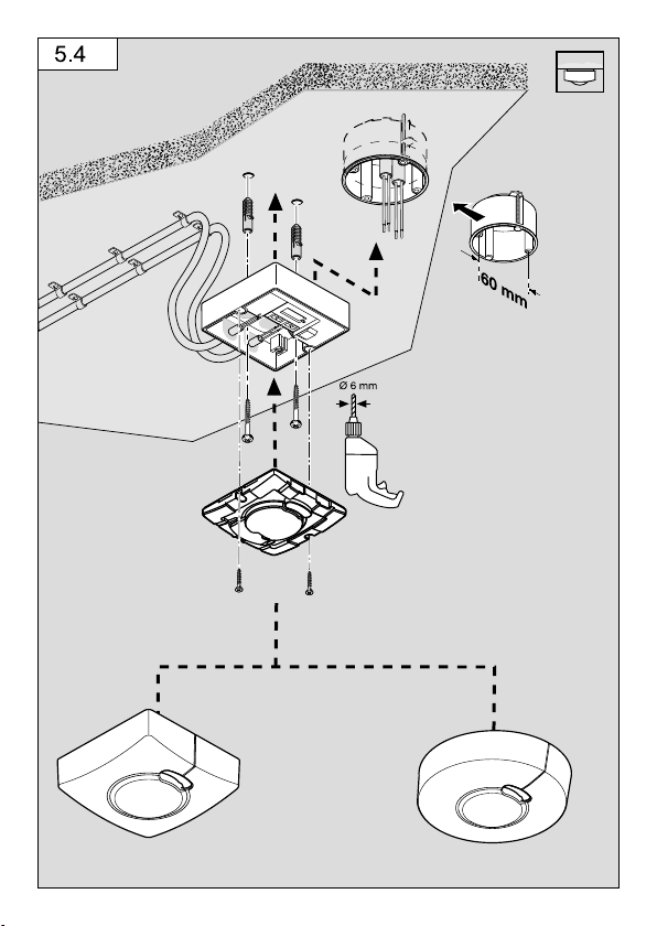
Deckenmontage Aufputz-Zuleitung (Abb�5�4)
Zur Wandmontage ist neben den Dichtgummies ein Entwässerungsloch angedeutet
(Ø 5mm Bohrer). Dies muss bei Bedarf geönet werden. (Abb�5�3)
Zur Montage des HF3360LiveLink ist optional ein Eckwandhalter erhältlich.
(Art.-Nr. 035174 weiß).
12
Page 13

• Stromversorgung abschalten� (Abb�5�1)
• Designblende vom Sensormodul trennen.
• Sensormodul vom Lastmodul trennen.
• Netzanschluss vornehmen.
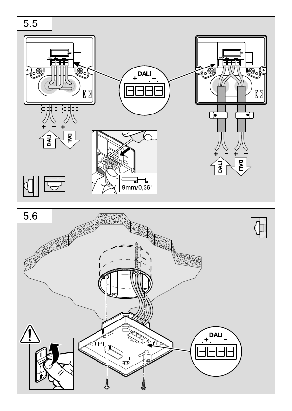
- Aufputz-Zuleitung (Abb�5�5)
- Unterputz-Zuleitung (Abb�5�6)
• Befestigungsschrauben einsetzen und Lastmodul montieren.
• Sensor- und Lastmodul zusammenstecken und verschrauben.
• Stromversorgung einschalten. (Abb�5�6)
• Designblende aufstecken.
• Funktionseinstellungen vornehmen. (➔"6�Funktion")
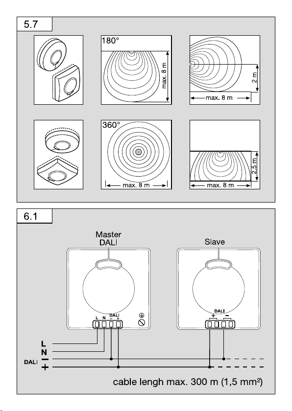
• Erfassungsbereich/Reichweite (Abb� 5�7)
6� Funktion/Bedienung
Nachdem der Anschluss vorgenommen, das Gerät geschlossen und die Linse
aufgesetzt ist, kann die Anlage in Betrieb genommen werden.
Master/Slave
Der HF3360LiveLink ist für den Einsatz in Master-Slave-Netzen geeignet. Dabei ist
der DALI-Sensor Master, der LiveLink-Sensor ist Slave.
Der Master-/Slave-Betrieb erlaubt es, größere Raume zu erfassen. Die Auswertung
der Helligkeit im Raum erfolgt ausschließlich am Master. Die Slaves melden die Bewegungserfassung dem Master. Die Schaltung der Beleuchtung erfolgt ausschließlich
über den Master. Es können bis zu 30 Teilnehmer angeschlossen werden.
Anschlussbeispiel (Abb� 6�1)
Wichtig: Die Einstellungen erfolgen über die LiveLink-Box via App.
– Dämmerungseinstellung
– Zeiteinstellung
– Halb-/Vollautomatik
– Konstantlichtreglung
– Vernetzung mehrerer Sensoren
– Teachmodus
– Testbetrieb
– Tageslichtbetrieb
– IQ-Modus
– Grundhelligkeit
Mit einem DALI-Bus wird der Sensor an die LiveLink-Box als Steuergerät angebunden.
Der Sensor nutzt die DALI-Leitung zur Kommunikation mit der LiveLink-Box und
zur Spannungsversorgung. Die LiveLink-Sensoren funktionieren ausschließlich im
LiveLink-System als Bereichserweiterung mit geeigneten STEINEL DALI-Sensoren.
DE
13
Page 14
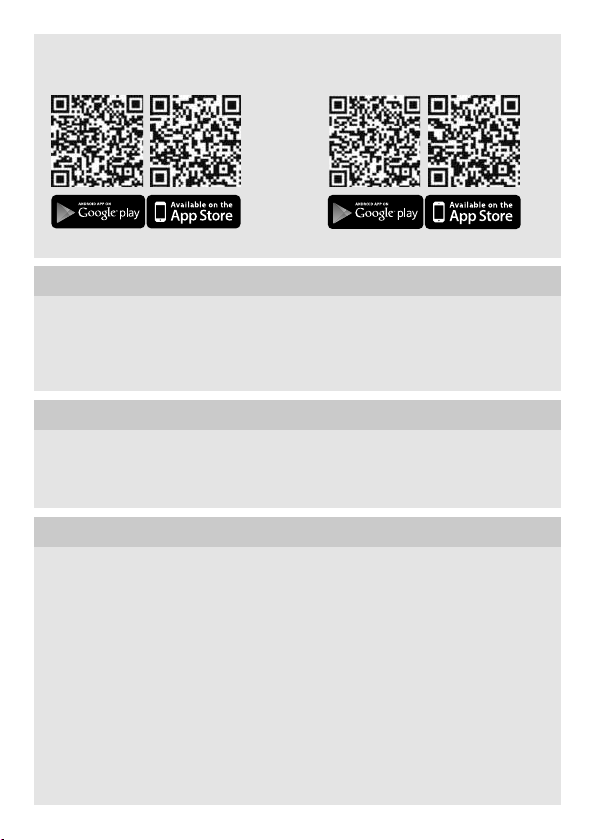
Reichweiteneinstellung über LiveLink-Apps
Inbetriebnahme App: LiveLink Install Bedienungs-App: LiveLink Control
7� Betrieb/Pflege
Der Sensor eignet sich zur automatischen Schaltung von Licht. Für spezielle
Einbruchalarmanlagen ist das Gerät nicht geeignet, da die hierfür vorgeschriebene
Sabotagesicherheit fehlt. Die Oberfläche kann bei Verschmutzung mit einem feuchten
Tuch (ohne Reinigungsmittel) gesäubert werden.
8� EG-Konformitätserklärung
Hiermit erklärt STEINEL Vertrieb GmbH, dass der Funkanlagentyp HF3360LiveLink
der Richtlinie 2014/53/EU entspricht. Der vollständige Text der EU-Konformitätserklärung ist unter der folgenden Internetadresse verfügbar: http://www.steinel.de
9� Garantieerklärung
Als Käufer stehen Ihnen die gesetzlich vorgeschriebenen Rechte gegen den Verkäufer
zu. Soweit diese Rechte in Ihrem Land existieren, werden sie durch unsere Garantieerklärung weder verkürzt noch eingeschränkt. Wir geben Ihnen 5Jahre Garantie auf
die einwandfreie Beschaenheit und ordnungsgemäße Funktion Ihres STEINELProfessional-Sensorik-Produktes. Wir garantieren, dass dieses Produkt frei von Material-, Herstellungs- und Konstruktionsfehlern ist. Wir garantieren die Funktionstüchtigkeit aller elektronischen Bauteile und Kabel, sowie die Mangelfreiheit aller eingesetzten
Werkstoe und deren Oberflächen.
14
Page 15
Geltendmachung
Wenn Sie Ihr Produkt reklamieren wollen, senden Sie es bitte vollständig und
frachtfrei mit dem Original-Kaufbeleg, der die Angabe des Kaufdatums und der
Produktbezeichnung enthalten muss, an Ihren Händler oder direkt an uns, die
STEINEL Vertrieb GmbH - Reklamationsabteilung - Dieselstraße 80-84,
33442 Herzebrock-Clarholz. Wir empfehlen Ihnen daher Ihren Kaufbeleg bis
zum Ablauf der Garantiezeit sorgfältig aufzubewahren. Für Transportkosten und
-risiken im Rahmen der Rücksendung übernimmt STEINEL keine Haftung.
Informationen zur Geltendmachung eines Garantiefalles erhalten Sie auf unserer
Homepage www�steinel-professional�de/garantie
Wenn Sie einen Garantiefall haben oder eine Frage zu Ihrem
Produkt besteht, können Sie uns jederzeit gerne unter der
Service-Hotline +49 (0) 52 45 / 448 - 188 anrufen.
10� Technische Daten
Abmessungen
(L×B×H)
Leistungsaufnahme LiveLink-Box 9 mA / 5 DALI-Teilnehmer,
LiveLink Ausgang 1 DALI-Steuerleitung (multimasterfähig zur Kommunikation
Erfassungswinkel 360° mit 180° Önungswinkel
Einsatzort im Innenbereich von Gebäuden
Sensorik 5,8GHz Hochfrequenz
Sendeleistung ca. 1mW
Helligkeitsmessung 2 - 1000Lux
Schutzart Aufputz: IP54 Unterputz: IP20
Temperaturbereich - 20°C bis + 50°C
Montagehöhe 2 - 2,8 m
Aufputz rund Ø
Aufputz eckig
Unterputz rund Ø
Unterputz eckig
12-22,5 V
, no SELV
mit der LiveLink-Box)
126×52mm
95×95×52mm
124×64mm
94×94×64mm
DE
15
Page 16

11� Betriebsstörungen
Störung Ursache Abhilfe
Sensor ohne Spannung
Sensor schaltet nicht ein
Sensor schaltet nicht aus
Sensor schaltet immer
EIN/AUS
n Sicherung hat ausgelöst,
nicht eingeschaltet,
Leitung unterbrochen
n Kurzschluss
n Glühlampe defekt
n bei Tagesbetrieb,
Dämmerungseinstellung
steht auf Nachtbetrieb
n Sicherung hat ausgelöst
n dauernde Bewegung im
Erfassungsbereich
n weiterer Sensor parallel
geschaltet und noch aktiv
n Gardine, Blume etc. be-
wegt sich im Erfassungsbereich des Sensors und
schaltet durch Bewegung neu
n Sensor in der Nähe von
WLAN oder anderer
Funkquelle
n Sicherung einschalten,
tauschen, Netzschalter
einschalten, Leitung mit
Spannungsprüfer überprüfen
n Anschlüsse überprüfen
n Glühlampe austauschen
n neu einstellen
n Sicherung einschalten,
tauschen, evtl. Anschluss
überprüfen
n Bereich kontrollieren
n Zeiteinstellung des ande-
ren Sensors abwarten
n Bereich kontrollieren
n mindestens 2 m von
der Funkquelle entfernt
installieren
16
Page 17
GB
!
!
1� About this document
– Please read carefully and keep in a safe place.
– Under copyright. Reproduction either in whole or in part only with our consent.
– Subject to change in the interest of technical progress.
Symbols
Hazard warning!
Reference to other information in the document�
...
2� General safety precautions
Disconnect the power supply before attempting any work on the sensor�
• During installation, the electric power cable to be connected must not be live.
Therefore, switch o the power first and use a voltage tester to make sure the
wiring is o-circuit.
• Installing the sensor involves work on the mains power supply. This work must
therefore be carried out professionally in accordance with national wiring regulations and electrical operating conditions. (e.g. DE-VDE 0100, AT-ÖVE-EN 1,
CH-SEV 1000)
3� HF3360LiveLink
Proper use
– Sensor suitable for indoor wall and ceiling-mounting
The HF3360LiveLink is an active motion detector. It responds to the slightest
movement regardless of temperature. The integrated HF sensor emits high-frequency
electromagnetic waves (5.8 GHz) and receives their echo. In response to the slightest
movement in the detection zone, the change in echo is perceived by the sensor.
A microprocessor then issues the switch command "switch light ON". Detection is
possible through doors, panes of glass or thin walls.
Package contents for surface-mounted installation (Fig�3�1)
Package contents for concealed installation (Fig�3�2)
GB
17
Page 18

Product components (Fig� 3�3)
A Load module, power supply lead, surface-mounted
B Load module, power supply lead, concealed
C Designer trim, round or square
D Sensor module
Product dimensions
Ceiling / wall mounting / surface-mounted and concealed wiring (Fig�3�4)
4� Electrical installation
For wiring up the motion detector, the following applies: Under section 6 of
VDE0100520, a multiple-core lead containing both the mains voltage leads and
the control leads (e.g. NYM 5 × 1.5) may be used for the wiring between sensor and
LiveLink Box. The lead between LiveLink Box and sensor must be no longer than
300m (for 1.5mm²). After installing and switching on, the LiveLink Box takes approx.
45seconds to start.
The sensor then starts to flash once per second during the initialisation cycle.
Wiring example (Fig�4�1)
– Surface-mounted installation
If the rubber seal is damaged, the cable entry openings must be sealed with an M16
or M20 (at least IP54) double seal cable gland.
5� Mounting
• Check all components for damage.
• Do not use the product if it is damaged.
• Select an appropriate mounting location, taking the reach and motion detection
into consideration.
Installation procedure
Wall-mounting, concealed power supply lead (Fig�5�1)
Ceiling mounting, concealed power supply lead (Fig�5�2)
Wall-mounting, surface-mounted power supply lead (Fig�5�3)
Ceiling mounting, surface-mounted power supply lead (Fig�5�4)
For mounting on the wall, a water drainage hole (Ø 5mm drill bit) is marked next to
the rubber seal. This must be opened if necessary. (Fig�5�3)
18
Page 19

An optional corner wall mount is available for mounting the HF3360LiveLink.
(Prod. no. 035174 white).
• Switch OFF power supply� (Fig�5�1)
• Detach designer trim from sensor module.
• Disconnect sensor module from the load module.
• Connect to mains power supply.
- Surface-mounted power supply lead (Fig�5�5)
- Concealed power supply lead (Fig�5�6)
• Insert fastening screws and mount load module.
• Fit sensor and load module together and screw into place.
• Switch ON power supply. (Fig�5�6)
• Fit decorative trim panel.
• Set functions. (➔"6�Function")
• Detection zone / reach (Fig� 5�7)
6� Function / operation
Once you have connected the unit, closed the housing and fitted the lens, you are
ready to put the system into operation.
Master/slave
The HF3360LiveLink is suitable for use in master/slave networks. In this case, the
DALI sensor is the master, the LiveLink sensor the slave.
The master/slave configuration permits detection of movement in larger rooms or
spaces. The level of brightness prevailing in the room is only evaluated at the master.
The slaves report movements detected to the master. Lighting is switched ON and
OFF via the master only. As many as 30 users can be connected.
Wiring example (Fig� 6�1)
Important: The settings are made via the LiveLink Box via app.
– Twilight setting
– Time setting
– Semi/fully automatic
– Constant-lighting control
– Interconnecting several sensors
– Teach mode
– Test mode
– Daylight operation
– IQ mode
– Basic brightness
GB
19
Page 20
The sensor is connected to the LiveLink Box as a control unit via a DALI bus. The
sensor uses the DALI line for communicating with the LiveLink Box and for supplying
power. To extend the detection zone, the LiveLink sensors only work in the LiveLink
system with suitable STEINEL DALI sensors.
Reach setting via LiveLink apps
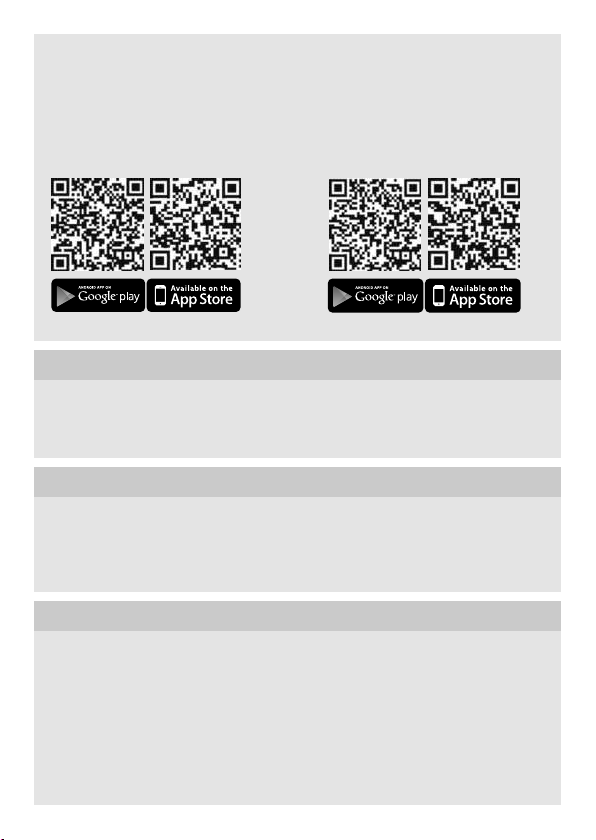
Start-up app: LiveLink Install Control app: LiveLink Control
7� Operation/maintenance
The Sensor is suitable for switching on a light automatically. The unit is not suitable
for burglar alarm systems as it is not tamperproof in the manner prescribed for such
systems. The surface can be cleaned with a damp cloth (without detergents) if dirty.
8� EC Declaration of Conformity
STEINEL Vertrieb GmbH hereby declares that the HF3360LiveLink radio equipment
type conforms to Directive 2014/53/EU. The full wording of the EU Declaration of
Conformity is available for downloading from the following Internet address:
http://www.steinel.de
9� Warranty Declaration
As purchaser, you are entitled to your statutory rights against the vendor. If these
rights exist in your country, they are neither curtailed nor restricted by our Warranty
Declaration. We guarantee that your STEINEL Professional sensor product will remain
in perfect condition and proper working order for a period of 5years. We guarantee
that this product is free from material-, manufacturing- and design flaws. In addition,
we guarantee that all electronic components and cables function in the proper manner and that all materials used and their surfaces are without defects.
20
Page 21
Making Claims
If you wish to make a claim, please send your product complete and carriage paid
with the original receipt of purchase, which must show the date of purchase and
product designation, either to your retailer or contact us at STEINEL (UK) Limited,
25Manasty Road, Axis Park, Orton Southgate, Peterborough, PE2 6UP, for a returns number. For this reason, we recommend that you keep your receipt of purchase
in a safe place until the warranty period expires. STEINEL shall assume no liability for
the costs or risks involved in returning a product.
For information on making claims under the terms of the warranty, please go to
www�steinel-professional�de/garantie
If you have a warranty claim or would like to ask any question
regarding your product, you are welcome to call us at any time
on our Service Hotline 01733 366700.
10� Technical specifications
Dimensions
(L×W×H)
Power consumption LiveLink Box 9 mA / 5 DALI users,
LiveLink output 1 DALI control line (multi-master capability for communication
Angle of coverage 360° with 180° angle of aperture
Application inside buildings
Sensor system 5.8GHz high frequency
Transmitter power approx. 1mW
Brightness measurement 2 - 1000lux
IP rating Surface-mounted: IP54 Concealed: IP20
Temperature range -20°C to +50°C
Mounting height 2 – 2.8 m
Surface-mounted installation, round Ø
Surface-mounted installation, square
Concealed installation, round Ø
Concealed installation, square
12-22.5 V
, no SELV
with the LiveLink Box)
126×52mm
95×95×52mm
124×64mm
94×94×64mm
GB
21
Page 22

11� Troubleshooting
Malfunction Cause Remedy
No power at the sensor
Sensor will not switch
ON
Sensor will not switch
OFF
Sensor keeps switching
ON/OFF
n Fuse has tripped,
not switched ON,
break in wiring
n Short circuit
n Bulb faulty
n Twilight setting set to
night-time mode during
daytime operation
n Fuse has tripped
n Continuous movement
in the detection zone
n Another sensor is
parallel-connected and
still active
n Curtains, plant etc.
moving in the sensor's
detection zone causing
the sensor to respond
n Sensor near Wi-Fi or
other wireless communication source
n Activate, change fuse,
turn ON power switch,
check wiring with
voltage tester
n Check connections
n Change bulb
n Adjust setting
n Activate, change fuse,
check connection if
necessary
n Check zone
n Wait for time setting
of the other sensor to
elapse
n Check zone
n Install at least 2 m away
from the wireless communication source
22
Page 23

Page 24

DE STEINEL Vertrieb GmbH
Dieselstraße 80-84 · 33442 Herzebrock-Clarholz
Tel: +49/5245/448-188
www.steinel.de
AT Steinel Austria GmbH
Hirschstettner Strasse 19/A/2/2 · A-1220 Wien
Tel.: +43/1/2023470 · [email protected]
CH PUAG AG
Oberebenestrasse 51 · CH-5620 Bremgarten
Tel.: +41/56/6488888 · [email protected]
GB STEINEL U.K. LTD.
25, Manasty Road · Axis Park · Orton Southgate
GB-Peterborough Cambs PE2 6UP
Tel.: +44/1733/366-700 · [email protected]
IE Socket Tool Company Ltd
Unit 714 Northwest Business Park
Kilshane Drive Ballycoolin · Dublin 15
Tel.: 00353 1 8809120 · [email protected]
FR STEINEL FRANCE SAS
ACTICENTRE - CRT 2
Rue des Famards - Bât. M - Lot 3
F-59818 Lesquin Cedex
Tél.: +33/3/20 30 34 00 · [email protected]
NL Van Spijk B.V.
Postbus 2 · 5688 HP OIRSCHOT
De Scheper 402 · 5688 HP OIRSCHOT
Tel. +31 499 571810
[email protected] · www.vanspijk.nl
BE VSA Belgium
Hagelberg 29 · B-2440 Geel
Tel.: +32/14/256050
[email protected] · www.vsabelgium.be
LU Minusines S.A.
8, rue de Hogenberg · L-1022 Luxembourg
Tél. : (00 352) 49 58 58 1 · www.minusines.lu
ES SAET-94 S.L.
C/ Trepadella, n° 10 · Pol. Ind. Castellbisbal Sud
E-08755 Castellbisbal (Barcelona)
Tel.: +34/93/772 28 49 · [email protected]
IT STEINEL Italia S.r.l.
Largo Donegani 2 · I-20121 Milano
Tel.: +39/02/96457231
[email protected] · www.steinel.it
PT F.Fonseca S.A.
Rua Joao Francisco do Casal 87/89 Esgueira
3800-266 Aveiro - Portugal
Tel. +351 234 303 900
[email protected] · www.ffonseca.com
SE KARL H STRÖM AB
Verktygsvägen 4 · SE-553 02 Jönköping
Tel.: +46 36 550 33 00 · [email protected] · www.khs.se
DK Roliba A/S
Hvidkærvej 52 · DK-5250 Odense SV
Tel.: +45 6593 0357 · www.roliba.dk
FI Oy Hedtec Ab
Lauttasaarentie 50 · FI-00200 Helsinki
Puh.: +358/207 638 000
[email protected] · www.hedtec.fi/valaistus
NO Vilan AS
Olaf Helsetsvei 8 · N-0694 Oslo
Tel.: +47/22725000
[email protected] · www.vilan.no
GR PANOS Lingonis + Sons O. E.
Aristofanous 8 Str. · GR-10554 Athens
Tel.: +30/210/3212021 · [email protected]
TR SAOS Teknoloji Elektrik Sanayi ve Ticaret Limited Şirketi
Halil Rıfat Paşa mahallesi Yüzerhavuz Sokak
PERPA Ticaret Merkezi A Blok Kat 5 No.313 · Şişli / İSTANBUL
Tel.: +90 212 220 09 20
[email protected] · www.saosteknoloji.com.tr
CZ ELNAS s.r.o.
Oblekovice 394 · CZ-67181 Znojmo
Tel.: +420/515/220126
[email protected] · www.elnas.cz
PL „LŁ“ Spółka z ograniczoną odpowiedzialnością sp.k.
Byków, ul. Wrocławska 43 · PL-55-095 Mirków
Tel.: +48 71 3980818
[email protected] · www.langelukaszuk.pl
HU DINOCOOP Kft
Radvány u. 24 · H-1118 Budapest
Tel.: +36/1/3193064 · [email protected]
LT KVARCAS
Neries krantine 32 · LT-48463, Kaunas
Tel.: +370/37/408030 · [email protected]
EE Fortronic AS
Tööstuse tee 10 · EST-61715 Tõrvandi
Ülenurme vald, Tartumaa
Tel.: +372/7/475208
[email protected] · www.fortronic.ee
SI ELEKTRO – PROJEKT PLUS D.O.O.
Suha pri Predosljah 12 SLO-4000 Kranj
PE GRENC 2 · 4220 Škofja Loka
Tel.: 00386-4-2521645 · GSM: 00386-40-856555
[email protected] · www.priporocam.si
SK NECO SK, A.S.
Ružová ul. 111 · SK-01901 Ilava
Tel.: +421/42/4 45 67 10
[email protected] · www.neco.sk
RO Steinel Distribution SRL
Parc Industrial Metrom
RO-500269 Brasov · Str. Carpatilor nr. 60
Tel.: +40(0)268 53 00 00 · www.steinel.ro
HR Daljinsko upravljanje d.o.o.
Bedricha Smetane 10 · HR-10000 Zagreb
t/ 00385 1 388 66 77
[email protected] · www.daljinsko-upravljanje.hr
LV Ambergs SIA
Brivibas gatve 195-16 · LV-1039 Riga
Tel.: 00371 67550740 · www.ambergs.lv
BG ТАШЕВ-ГАЛВИНГ ООД
Бул. Климент Охридски № 68
1756 София, България
Тел.: +359 2 700 45 45 4
[email protected] · www.tashev-galving.com
RU Best - Snab
ул.1812 года, дом 12 · 121127 Москва · Россия
Tel: +7 (495) 280-35-53
[email protected] · www.steinel.su
CN STEINEL China
Representative Office
Shanghai Rm. 25 A · Huadu Mansion No. 838
Zhangyang Road Shanghai 200122
Tel: +86 21 5820 4486
[email protected] · [email protected] · www.steinel.cn
110055016 08/2017_K Technische Änderungen vorbehalten. / Subject to technical modification without notice.
 Loading...