

Page 1

Heißluftgebläse
HG 4000 E
HG 5000 E
8015401 Technische Änderungen vorbehalten.
Bedienungsanleitung
D
Operating instructions
GB
Mode d’emploi
F
Gebruiksaanwijzing
NL
Istruzioni per l'uso
I
Instrucciones de montaje
E
Bruksanvisning
S
Betjeningsvejledning
DK
Käyttöohje
FIN
Bruksanvisning
N
D
STEINEL-Schnell-Service
Dieselstraße 80-84 · 33442 Herzebrock-Clarholz
Tel: +49/5245/448-188 · Fax:+49/5245/448-197 · www.steinel.de
A
I. MÜLLER
Peter-Paul-Str. 15 · A-2201 Gerasdorf bei Wien
Tel.: +43/2246/2146 · Fax: +43/2246/25466 · www.imueller.at
PUAG AG
Oberebenestrasse 51 · CH-5620 Bremgarten
Tel.: +41/56/6488888 · Fax: +41/56/6488880 · www.puag.ch
STEINEL U.K. LTD.
37, Manasty Road · Orton Southgate · GB-Peterborough PE2 6UP
Tel.: +44/1733/238-265 · Fax: +44/1733/238-270
www.steineluk.com
STC SOCKET TOOL COMPANY Limited
8, Queen Street, Smithfield · IRL-Dublin 7
Tel.: +353/1/8725433 · Fax: +353/1/8725195
sockettool@eircom.net
F
DUVAUCHEL S.A.
ACTICENTRE - CTR 2
Rue des Famards - Bat. M - Lot 3 · F-59818 Lesquin Cedex
Tél.: +33/3/20 3034 00 · Fax: +33/3/2030 34 20
www.duvauchel.com
VAN SPIJK AGENTUREN BV
Postbus 2 · NL-5688 ZH Oirschot
De Scheper 260 · NL-5688 HP Oirschot
Tel.: +31/499/571810 · Fax: +31/499/575795
www.vsa-hegema.nl
B
VSA handel Bvba
Fabriekstraat 145 · B-3900 Overpelt
Tel.: +32/11/660720 · Fax: +32/11/660729 ·www.vsahandel.be
L
A. R. Tech.
19, Rue Eugène Ruppert, Cloche D’Or · BP 1044
L-1010 Luxembourg
Tel.: +352/49/3333 · Fax: +352/40/2634 · www.artech.lu
I
THOELKE DISTRIBUZIONE S.N.C.
Via Adamello 2/4 · I-22070 Locate Varesino (Como)
Tel.: +39/331/836911 · Fax: +39/331/836913 · www.thoelke.it
E
SAET-94 S.L.
C/ Trepadella, n° 10 · Pol. Ind. Castellbisbal Sud
E-08755 Castellbisbal (Barcelona)
Tel.: +34/93/772 28 49 · Fax: +34/93/772 01 80 · www.saet94.com
P
Pronodis-Soluções
Tecnológicas, Lda · Rua do Caseiro no 87 A/B Vilar
P-3810-078 Aveiro
Tel.: +351/234/484031 · Fax: +351/234/484033 ·
www.
pronodis.pt
S
KARL H STRÖM AB
Verktygsvägen 4 · S-55302 Jönköping
Tel.: +46/36/31 42 40 · Fax: +46/36/31 42 49 · www.khs.se
BROMMANN ApS
Ellegaardvej 18 · DK-6400 Sønderborg
Tel.: +45/7442 8862 · Fax: +45/7443 43 60 · www.brommann.dk
Oy Hedtec Ab
Hedengren yhtiö · Lauttasaarentie 50 · FIN-00200 Helsinki
Tel.: +358/9/682881 ·Fax: +358/9/673813 · www.hedtec.fi/valaistus
N
Vilan AS
Tvetenveien 30 B · N-0666 Oslo
Tel.: +47/22725000 · Fax: +47/22725001 · www.vilan.no
PANOS Lingonis + Sons O. E.
Aristofanous 8 Str. · GR-10554 Athens
Tel.: +30/210/3212021 · Fax: +30/210/3218630
lygonis@otenet.gr
EGE SENSÖRLÜ AYDINLATMA ‹TH.
‹HR. T‹C. VE PAZ. LTD. fiT‹.
GERSAN SAN. S‹TES‹ 659.
SOKAK · NO:510 · BATIKENT/ANKARA
Tel.: +90/312/2571233 · Fax: +90/312/2556041
www.egeaydinlatma.com
ATERSAN ‹TH. T‹C. ve SAN. KOLL. ST‹
Add. Tersane Caddesi Galata Hirdavatcilar Carsisi No: 45
Karakoy / ‹stanbul – TURKEY
Tel.: +90/212/2920664 Pbx. · Fax: +90/212/2920665
www.atersan.com
ELNAS s.r.o.
Oblekovice 394 · CZ-67181 Znojmo
Tel.: +420/515/220126 · Fax: +420/515/244347
www.elnas.cz
LANGE ŁUKASZUK Sp.j.
Byków 25a · PL-55-095 Mirków
Tel.: +48/71/3 98 08 861 · Fax: +48/71/3 98 19
www.langelukaszuk.pl
H
DINOCOOP Kft
Radvány u. 24 · H-1118 Budapest
Tel.: 36/1/3193064 · Fax: +36/1/3193066
www.dinocoop.hu
KVARCAS
Neries krantine 32 · LT-48463, Kaunas
Tel.: +370/37/408030 · Fax: +370/37/408031 ·
www.
kvarcas.lt
FORTRONIC AS
Teguri 45c · EST 50113 Tartu
Tel.: +372/7/475208 · Fax: +372/7/367229 ·
www.
fortronic.ee
LOG Zabnica D.O.O.
Podjetje Za Trgovino · Srednje Bitnje 70
SLO-4209 Zabnica
Tel.: +386/42/312000 · Fax: +386/42/312331 ·
www.
log.si
Neco s.r.o.
Ruzová ul. 111 · SK-01901 Ilava
Tel.: +421/42/4 44 14 55 · Fax: +421/42/4 44 14 56
www.neco.sk
STEINEL Trading s.r.l.
Str. Lunga 123 · RO-507055 Cristian-Brasov
Tel.: +40/2 68/25 74 00 · Fax: +40/2 68/25 76 00
www.steinel.ro
Daljinsko Upravljanje d.o.o.
B. Smetane 10 · HR-10 000 Zagreb
Tel.: +3 85/1/3 88 02 47 · Fax: +3 85/1/3 88 02 47
daljinsko-upravljanje@zg.t-com.hr
Ambergs SIA
Brivibas gatve 195-16 · LV-1039 Riga
Tel.: +3 71/7/55 07 40 · Fax: +3 71/7/55 28 50
www.ambergs.lv
IT und R GmbH
Kuibyshev Str. 78 · RUS-620026 Ekaterinburg
Tel.: +7/34 32/24 23 23 · Fax: +7/34 32/61 61 65
itr@ural.ru
SVETILNIKI
Str. Malaya Ordinka, 39 · RUS-113184 Moskau
Tel.: +7/95/2 37 28 58 · Fax: +7/95/2 37 11 82
goncharov@o-svet.rz
Page 2

Sicherheitshinweise
Achtung! Beim Gebrauch
von Elektrowerkzeugen sind
zum Schutz gegen elektrischen Schlag, Verletzungsund Brandgefahr folgende
grundsätzliche Sicherheitsmaßnahmen zu beachten.
Lesen und beachten Sie
diese Hinweise, bevor Sie
das Gerät benutzen.
y
Wenn mit dem Gerät nicht
sorgsam umgegangen
wird, kann ein Brand entstehen.
y
Berücksichtigen Sie
Umgebungseinflüsse.
–
Setzen Sie Elektrowerkzeuge nicht dem Regen
aus.
–
Benutzen Sie Elektrowerkzeuge nicht im feuchten
Zustand und nicht in
feuchter oder nasser
Umgebung.
–
Vorsicht bei Gebrauch der
Geräte in der Nähe brennbarer Materialien. Nicht für
längere Zeit auf ein und
dieselbe Stelle richten.
–
Nicht bei Vorhandensein
einer explosionsfähigen
Atmosphäre verwenden.
–
Wärme kann zu brennbaren Materialien geleitet
werden, die verdeckt sind.
y
Schützen Sie sich vor
elektrischem Schlag.
–
Vermeiden Sie
Körperberührung mit geerdeten Teilen, zum Beispiel
Rohren, Heizkörpern,
Herden, Kühlschränken.
y
Das Gerät nicht unbeaufsichtigt lassen, solange es
in Betrieb ist.
y
Bewahren Sie Ihre
Werkzeuge sicher auf.
–
Gerät nach Gebrauch auf
Ständer auflegen und abkühlen lassen, bevor es
weggepackt wird.
–
Unbenutzte Werkzeuge
sollten im trockenen, verschlossenen Raum und für
Kinder nicht erreichbar
aufbewahrt werden.
y
Überlasten Sie Ihre Werkzeuge nicht.
–
Sie arbeiten besser und
sicherer im angegebenen
Leistungsbereich.
–
Nach längerem Gebrauch
des Gerätes bei 600° C
sollte vor dem Ausschalten
des Gerätes die
Temperatur gesenkt werden. Dies verlängert die
Lebensdauer der Heizung.
y
Achten Sie auf giftige
Gase und Entzündungsgefahr.
–
Bei der Bearbeitung von
Kunststoffen, Lacken und
ähnlichen Materialien können giftige Gase auftreten.
Achten Sie auf Brand- und
Entzündungsgefahr.
y
Zweckentfremden Sie
nicht das Kabel.
–
Tragen Sie das Werkzeug
nicht am Kabel und benutzen Sie es nicht, um den
Stecker aus der Steckdose zu ziehen. Schützen
Sie das Kabel vor Hitze, Öl
und scharfen Kanten.
y
Achtung
–
Zu Ihrer eigenen
Sicherheit benutzen Sie
nur Zubehör und
Zusatzgeräte, die in der
Bedienungsanleitung
angegeben oder vom
Werkzeug-Hersteller empfohlen oder angegeben
werden. Der Gebrauch
anderer als der in der
Bedienungsanleitung oder
im Katalog empfohlenen
Einsatzwerkzeuge oder
Zubehöre kann eine persönliche Verletzungsgefahr
für Sie bedeuten.
y
Reparaturen nur vom
Elektrofachmann.
–
Dieses Elektrowerkzeug
entspricht den einschlägigen Sicherheitsbestimmungen. Reparaturen dürfen nur von einer Elektrofachkraft ausgeführt werden, andernfalls können
Unfälle für den Betreiber
entstehen.
y
Bei Nichtbeachtung der
Bedienungsanleitung
kann das Gerät zu einer
Gefahrenquelle werden.
y
Bewahren Sie die Sicherheitshinweise gut auf.
2
HG 4000 E / HG 5000 E
3
Page 3

Inbetriebnahme
Das Gerät mit dem EIN-/AUSSchalter einschalten.
Mit dem Temperaturregler
die gewünschte Soll-Temperatur vorwählen (25° C–
600° C). Der Temperaturwert
sowie der Buchstabe „A“ zur
Kennzeichnung des Einstellmodus werden auf der LEDSegmentanzeige angezeigt.
Nachdem die Temperatur
vorgewählt wurde, schaltet
das Gerät automatisch nach
ca. 3 Sekunden auf
Temperatur-Istwertanzeige
um. Die Anzeige der Sollund Istwerte erfolgt in 10°CSchritten.
Die Luftmenge kann mit
dem Luftstromregler stufenlos reguliert werden.
Die Regelung entspricht den
neuesten Normen über Netzrückwirkungen (EN 61000-3-3
Flickernorm, EN 61000-3-2
Oberwellennorm).
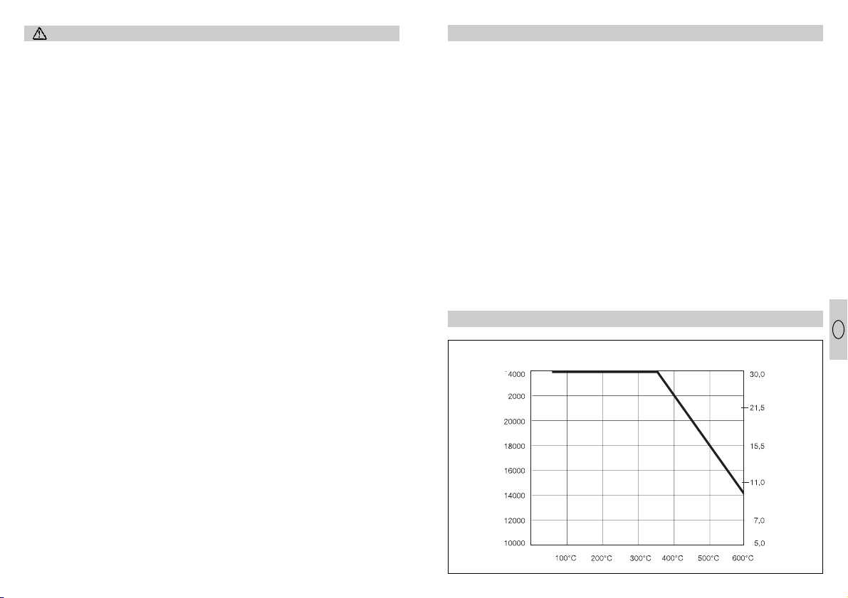
Das Gerät besitzt eine intelligente Temperatur- und Luft-
mengenregulierung. Diese
gibt stets der Temperatureinstellung den Vorrang (siehe
Diagramm). Beispiel: Um die
maximale Temperatur von
600° C zu erreichen, bei
gleichzeitiger Einstellung der
Drehzahl auf max. Luftförderung, regelt die Elektronik
automatisch die Luftmenge
soweit herunter, bis die
600° C erreicht werden.
Dementsprechend erhöht
sich die Luftmenge wieder,
sobald die Temperatur
gesenkt wird.
Intelligente Motor- und Temperatursteuerung
5
Intelligente Motor- und Temperatursteuerung
Dyn. Druck
(hPa)
Motordrehzalhl
(U/min.)
Austrittstemperatur
N
FIN DK S E I
NL
F
GB
D
0
Bedienungsanleitung
Gerätebeschreibung
Heißluftgebläse – Spezifikationen
y
Vollelektronische Temperatur- und Luftmengenregulierung
y
Luftmenge und Temperatur stufenlos einstellbar
y
Intelligente Motor- und Temperatursteuerung
y
Temperaturanzeige mit Soll- und Ist-Wert-Anzeige
y
Heizung leicht austauschbar
y
Bürstenloser Motor gewährt eine lange Lebensdauer
y
Stabiles einteiliges Gehäuse
y
Netzkabel ohne Öffnen des Gehäuses auswechselbar
Bauteile
Ausblasrohr (HG 4000 E: 40 mm, HG 5000 E: 50 mm)
Heizung
Stoßschutz
LED-Segmentanzeige
Temperaturregler
EIN-/AUS-Schalter
Luftstromregler
Technische Daten
HG 4000 E HG 5000 E
Spannung: 100 V 110 V 230–240 V /50 Hz 230–240 V /50 Hz
Leistung: 1500 W 1650 W 1750 W 3400 W
Temperatur: 25–600°C, stufenlos 25–600°C, stufenlos
Anzeigeart: LED-Segmentanzeige LED-Segmentanzeige
Luftmengenregulierung: stufenlos stufenlos
Luftmenge: max. 600 l/min. max. 800 l/min.
Luftdruck: 3000 Pa 3000 Pa
Ausblasrohr: Ø 40 mm Ø 50 mm
Lebensdauer Motor: ca. 20 000 Std. ca. 20 000 Std.
Lebensdauer Heizung: ca. 500–800 Std. ca. 500–800 Std.
Netzkabel: H07 RN-F 2 x 1 H07 RN-F 2 x 1,5
Länge: 2,5 m Länge: 2,5 m
Gewicht (ohne Netzkabel): 1115 g 1190 g
Abmessungen: Länge: 370 mm Länge: 350 mm
Ø 122 mm Ø 122 mm
(am Stoßschutz ) (am Stoßschutz )
4
D
Page 4

1. Wichtig! Das Gerät vom
Netz trennen.
2. Schrauben lösen und Abdeckkappe abziehen.
3. Zugentlastung lösen.
4. Netzklemmen lösen.
5. Kabel herausziehen.
6. Neues Kabel einlegen und
in umgekehrter Reihenfolge (1. Netzklemmen
festschrauben etc.) wieder
befestigen.
Heizungswechsel
Die Heizung des HG 4000 E
und des HG 5000 E ist
gesteckt und kann mit wenigen Handgriffen gewechselt
werden.
Jede Heizung enthält einen
Chip mit ihren spezifischen
Daten. Beim Einbau einer
neuen Heizung werden
deren Parameter von der
1. Wichtig! Das Gerät vom
Netz trennen.
2. Die 4 Schrauben am
Ende des Ausblasrohres
lösen.
3. Heizung abziehen und
gegen neue Heizung austauschen.
4. Ausblasrohr wieder festschrauben.
Regelelektronik übernommen.
Kabelwechsel
Ist das Netzkabel beschädigt, so kann es ohne
Öffnen des Gehäuses problemlos ausgetauscht werden.
b
c
a
d
a
b
c
d
6
Zubehör / Anwendungsbeispiele
Zubehör HG 4000 E
Winkelflachdüse 40 x 2
Anwendungen: Schweißen
von Kunststoffolien im Überlappschweißverfahren.
Reparaturarbeiten bei
Bitumendächern.
Winkelflachdüse 20 x 2
Anwendungen: Schweißen
von Kunststoffolien im Überlappschweißverfahren.
Runddüse 5 mm
Anwendungen:
Kunststoffschweißen.
Punktgenaues Erwärmen.
Runddüse 10 mm
Anwendungen:
Kunststoffschweißen.
Punktgenaues Erwärmen.
Einsatz mit Schweißschuh.
Schweißschuh
Anwendungen: Aufschiebbar
auf Runddüse 10 mm.
Schweißen mit KU-Schweißdraht.
Zubehör HG 5000 E
Flachdüse 70 x 10
Anwendungen: Bündelung
des Luftstromes.
Winkelflachdüse 74 x 3
Anwendungen: Schweißen
von Kunststoffolien im
Überlappungs-Schweißverfahren.
7
D
Page 5

Funktionsgarantie
Dieses STEINEL-Produkt ist
mit größter Sorgfalt hergestellt, funktions- und sicherheitsgeprüft nach geltenden
Vorschriften und anschließend einer Stichprobenkontrolle unterzogen.
Die Funktionsgarantie beträgt 12 Monate und beginnt
mit dem Tag des Verkaufs
an den Verbraucher. Wir
beseitigen Mängel, die auf
Material- oder Fabrikationsfehlern beruhen, die Garantieleistung erfolgt durch
Instandsetzung oder Austausch mangelhafter Teile
nach unserer Wahl. Eine
Garantieleistung entfällt für
Schäden an Verschleißteilen,
z.B. Heizung, Netzkabel, für
Schäden und Mängel, die
durch unsachgemäße
Behandlung oder Wartung
auftreten sowie für Bruch bei
Sturz.
Weitergehende Folgeschäden an fremden Gegenständen sind ausgeschlossen.
Die Garantie wird nur gewährt, wenn das unzerlegte
Gerät mit Kassenbon oder
Rechnung (Kaufdatum und
Händlerstempel), gut verpackt an die zutreffende
Servicestation eingesandt
oder in den ersten 6 Monaten dem Händler übergeben
wird.
Reparaturservice:
Nach Ablauf der Garantiezeit
oder Mängel ohne Garantieanspruch repariert unser
Werksservice. Bitte das Produkt gut verpackt an die
nächste Servicestation
senden
Konformitätserklärung
Das Produkt erfüllt die
Niederspannungsrichtlinie
73/23/EWG und die EMVRichtlinie 89/336/EWG.
Hilfswerkzeuge HG 4000 E / HG 5000 E
Andrückrolle
Anwendungen: Andrücken
von Kantenumleimern, PVCSchweißfolie usw.
Schweißdrahtandrückrolle
Anwendungen: Andrücken
von Schweißdrähten.
8
0
Operating Instructions
Features
Hot air gun – specifications
y
Fully electronic temperature and air flow monitoring
y
Air flow and temperature infinitely variable
y
Intelligent motor and temperature control
y
Temperature display showing target and actual temperature
y
Heating element easily changed
y
Brushless motor for long service life
y
Sturdy, one-piece housing
y
Power cord can be changed without opening the housing
Components
Hot air outlet nozzle (HG 4000 E: 40 mm dia., HG 5000 E: 50 mm dia.)
Heating element
Rubber bumper
LED segment display
Temperature regulator
ON/OFF switch
Air-flow switch
Technical Specifications
HG 4000 E HG 5000 E
Voltage: 100 V 110 V 230–240 V /50 Hz 230–240 V /50 Hz
Output: 1500 W 1650 W 1750 W 3400 W
Temperature: 25–600°C, 25–600°C,
infinitely variable infinitely variable
Display type: LED segment display LED segment display
Air-flow control: Infinitely variable Infinitely variable
Max. air-flow rate: max. 600 l/min. max. 800 l/min.
Air pressure: 3000 Pa 3000 Pa
Air outlet nozzle: 40 mm dia. 50 mm dia.
Motor service life: approx. 20 ,000 hrs. approx. 20,000 hrs.
Heating element service life: approx. 500–800 hrs. approx. 500–800 hrs.
Power cord: H07 RN-F 2 x 1 H07 RN-F 2 x 1,5
Length: 2.5 m Length: 2.5 m
Weight (without power cord): 1115 g 119 0 g
Dimensions: Length: 370 mm Length: 350 mm
122 mm dia. 122 mm dia.
(at rubber bumper ) (at rubber bumper )
9
GB
Page 6

Safety Notification
Caution! When using electric
power tools, observe the following basic safety precautions to avoid electric shock
as well as the risk of injury
and fire. Read and observe
this information before using
the tool.
y
Fire may be caused if the
tool is not used with care.
y
Take ambient conditions
into account.
–
Do not expose power tools
to rain.
–
Do not use power tools
when they are damp or in
damp or wet surroundings.
–
Exercise care when using
the tool in the proximity of
combustible materials. Do
not direct the tools at one
and the same place for a
prolonged period.
–
Do not use in the presence of an explosive
atmosphere.
–
Heat may be conducted to
combustible materials that
are out of sight.
y
Protect yourself from
electric shock.
–
Avoid touching grounded
equipment, such as piping,
radiators, cookers, refrigerators.
y
Do not leave the appliance unattended while in
operation.
y
Store your tools in a safe
place.
–
Place tool on its stand
after use and allow to cool
before storage.
–
Tools that are not in use
should be stored in a dry,
locked room and be out of
the reach of children.
y
Do not overload the tool.
–
Your work results and
safety will be enhanced if
you operate the tool within
the specified output range.
–
After using the tool for a
prolonged period at
600° C, you should reduce
the temperature before
switching it off. This will
prolong the service life of
the heating element.
y
Beware of toxic gases
and ignition hazards.
–
Toxic gases may occur
when working on plastics,
paints, varnishes or similar
materials. Beware of fire or
ignition hazards.
y
Do not misuse the power
cord.
–
Do not carry the tool by
the power cord and do not
use it to pull the plug from
the power socket outlet.
Protect the power cord
from heat, oil and sharp
edges.
y
Caution
–
For your own safety, use
only accessories and
attachments that are given
in the operating instructions or recommended or
specified by the tool
manufacturer. Using
attachments or accessories other than those
recommended in the
operating instructions or
catalogue may result in
personal injury.
y
Repairs only by qualified
electricians.
–
This power tool complies
with the relevant safety
regulations. Repairs
should only be performed
by a qualified electrician,
otherwise the user may
run the risk of accidents.
y
Failure to observe the
operating instructions
may turn the tool into a
source of danger.
y
Keep these safety notifications in a safe place.
Operation
Switch the tool on with
ON/OFF switch .
Use temperature switch to
preset the target temperature you require (25° C - 600°
C). The temperature setting
as well as the letter "A" to
show the setting mode will
appear on the LED segment
display. Once the temperature has been preset, the
tool will automatically display the actual temperature
after approx. 3 seconds.
Target and actual temperature is displayed in increments
of 10° C.
The air flow rate may be
infinitely varied using the
airflow regulator.
The control system complies
with the latest standards on
mains pollution
(EN 61000-3-3 Flicker
standard, EN 61000-3-2
Harmonics standard).
The tool features an intelligent temperature and
airflow control system that
always gives priority to temperature setting (see graph).
Example: To attain the maximum temperature of 600° C
with speed set to max. air
flow rate, the electronics will
automatically reduce air flow
until 600° C is reached. The
airflow rate will then increase again as soon as the
temperature is reduced.
Intelligent Motor and Temperature Monitoring
Intelligent Motor and Temperature Monitoring
Motor speed
(rpm)
Dyn. pressure
(hPa)
Outlet temperature
10 11
GB
Page 7

1. Important! Disconnect
tool from power supply.
2. Undo screws and detach
cover cap .
3. Release cable grip .
4. Undo mains terminals .
5. Pull out cable .
6. Insert new cable and
secure in reverse order
(first tighten mains terminals, etc.).
Changing Heating Element
The plug-in HG 4000 E/
HG 5000 E heating element
can be changed/replaced
within seconds.
Each heating element contains a chip that holds its
specific data. When a new
heating element is installed,
its parameters will be
1. Important! Disconnect
tool from power supply.
2. Undo the 4 screws at the
end of the outlet nozzle.
3. Pull off heating element
and replace with new one.
4. Firmly re-secure output
nozzle.
adopted by the control electronics.
Changing Power Cord
Accessories / Example Applications
Accessories for HG 4000 E
40 x 2 offset flat nozzle
Applications: Plastic sheet
welding using the lap weld
process. Repair work on
bitumen roofs.
20 x 2 offset flat nozzle
Applications: Plastic sheet
welding using the lap weld
process.
5 mm round nozzle
Applications: Plastics
welding. Spot heating.
10 mm round nozzle
Applications: Plastics
welding. Spot heating. Use
with welding nozzle.
Welding nozzle
Applications: Pushes onto
10 mm round nozzle.
Welding with plastic welding
wire.
Accessories for HG 5000 E
70 x 10 flat nozzle
Applications: For concen-
trating air flow.
74 x 3 offset flat nozzle
Applications: Plastic sheet
welding using the lap weld
process.
If the power cord becomes
damaged it can be changed/
replaced easily without
opening the housing.
b
c
a
b
c
d
a
d
12 13
GB
Page 8

Functional Guarantee
This STEINEL product has
been manufactured with
great care, performance
and safety tested according to current regulations,
and then subjected to a
batch test.
STEINEL guarantees that it
is in perfect condition and
functions correctly. The
correct working order of this
product is guaranteed for a
period of 12 months commencing on the date of sale
to the user. All defects due
to faulty material or manufacturing will be corrected.
This warranty does not
cover damage to wear parts,
e.g. heating element, power
cord, or damage and faults
caused by incorrect operation and maintenance.
Breakage due to a fall is
also not covered.
Further consequential
damage to other items is
excluded.
Claims under the guarantee
will only be granted if the
product, not disassembled,
with sales slip or invoice
(date of purchase and
dealer’s stamp) is sent, well
packed, to the appropriate
Service Centre, or handed
in to the dealer within the
first 6 months.
Repair-Service
Our customer service department will repair faults
not covered by the guarantee, or after the guarantee
has expired. Please send
the product, well packed, to
the nearest Service Centre.
Declaration of conformity
This product is in conformity with standards of low
voltage in accordance with
the regulations 73/23/EEC,
89/336/EEC.
Auxiliary tools for HG 4000 E / HG 5000 E
Feed roller
Applications: For pressing
down edgebands, PVC filler
strip.
Welding wire feed roller
Applications: For pressing
down welding wire.
14
2
0
Mode d'emploi
Description de l'appareil
Générateur d’air chaud – Spécifications
y
Réglage électronique de la température et du débit d'air
y
Réglage en continu du débit d'air et de la température
y
Commande intelligente du moteur et de la température
y
Affichage de la température avec valeur souhaitée et valeur effective
y
Résistance facile à remplacer
y
Le moteur sans balai garantit une durée de vie élevée
y
Boîtier robuste en un élément
y
Changement du câble secteur possible sans ouverture du boîtier de l'appareil
Composants
Tuyère de propulsion d'air (HG 4000 E: 40 mm, HG 5000 E: 50 mm)
Chauffage
Protection antichoc
Afficheur à segments LED
Régulateur de température
Interrupteur MARCHE/ARRÊT
Réglage du débit d'air
Caractéristiques techniques
HG 4000 E HG 5000 E
Tension: 100 V 110 V 230–240 V/50 Hz 230–240 V/50 Hz
Puissance: 1500 W 1650 W 1750 W 3400 W
Température: 25–600°C, en continu 25–600° C, en continu
Type d'affichage: affichage LED affichage LED
à segments à segments
Réglage du débit d'air: en continu en continu
Débit d'air: 600 l/min maxi 800 l/min maxi
Pression d'air: 3000 Pa 3000 Pa
Tube de propulsion d'air: Ø 40 mm Ø 50 mm
Durée de vie du moteur: env. 20 000 h env. 20 000 h
Durée de vie de
la résistance: env. 500-800 h. env. 500-800 h
Câble secteur : H07 RN-F 2 x 1 H07 RN-F 2 x 1,5
Longueur: 2,5 m Longueur: 2,5 m
Poids (sans câble secteur): 1115 g 119 0 g
Dimensions: Longueur: 370 mm Longueur: 350 mm
Ø 122 mm Ø 122 mm
(au niveau de (au niveau de la
la protection antichoc ) protection antichoc )
15
F
F
Page 9

Consignes de sécurité
Attention! Lors de l'utilisati-
on d'outillage électrique, il
est absolument impératif de
respecter les consignes de
sécurité suivantes afin de se
protéger des accidents électriques, des risques de blessure et d'incendie.
Veuillez lire ces consignes
avant d'utiliser l'appareil.
y
Un incendie peut survenir
si l'appareil n'est pas
manié avec précaution.
y
Tenez compte des conditions ambiantes.
–
N'exposez jamais l'outillage électrique à la pluie.
–
N'utilisez jamais l'appareil
si vous ou l'appareil êtes
mouillés ou vous trouvez
dans un environnement
humide.
–
Ne pas utiliser l'appareil à
proximité de matières
inflammables et ne pas le
diriger longtemps vers le
même endroit.
–
Ne pas utiliser l'appareil
en présence d'une atmosphère explosive.
–
La chaleur peut être transmise à des matériaux
inflammables cachés.
y
Protégez-vous contre les
accidents électriques.
–
Évitez de toucher des éléments mis à la terre
comme tuyaux, radiateurs,
cuisinières, réfrigérateurs.
y
Ne pas laisser l'appareil
sans surveillance tant
qu'il fonctionne.
y
Conservez votre outillage
en sûreté.
–
Après utilisation, poser
l'appareil sur son support
et le laisser refroidir avant
de le remballer.
–
Il faut conserver les outils
hors de portée des
enfants dans un local sec
et fermé.
y
Ne surchargez pas votre
outillage.
–
Vous travaillerez mieux et
de façon plus sûre en
respectant la plage de
puissance indiquée.
–
Après une utilisation prolongée de l'appareil à
600° C, réduisez la
température avant d'arrêter l'appareil. Vous augmentez ainsi la durée de
vie du chauffage.
y
Attention aux gaz et
vapeurs nocifs.
–
Si vous travaillez sur des
matières plastiques, des
peintures, des vernis ou
des produits similaires,
des émanations de gaz
toxiques peuvent se produire sous l'action de la
chaleur. Attention aux risques d'incendie et d'inflammation.
y
Utilisation du câble de
l'appareil en conformité
avec ses fonctions.
–
Ne vous servez jamais du
câble pour transporter
l'appareil ou débrancher la
fiche de la prise électrique. Protégez le câble de
la chaleur, de l'huile et des
arêtes coupantes.
y
Attention
–
Pour votre propre sécurité,
n'utilisez que des accessoires et appareils complémentaires indiqués
dans le mode d'emploi ou
conseillés ou indiqués par
le fabricant de l'outillage.
Vous pouvez vous blesser
en utilisant des outils ou
des accessoires autres
que ceux conseillés dans
le mode d'emploi ou le
catalogue.
y
Les réparations sont une
affaire de spécialiste.
–
Cet outillage électrique est
conforme à la réglementation de sécurité en
vigueur. Pour éviter les risques d'accident pour l'utilisateur, les réparations ne
doivent être confiées qu'à
un électricien professionnel.
y
En cas de non-respect du
mode d'emploi, l'utilisation de l'appareil peut être
dangereuse.
y
Conservez les consignes
de sécurité en lieu sûr.
Mise en service
Mettre l'appareil sous tension à l'aide de l'interrupteur
MARCHE/ARRÊT .
Sélectionner la température
souhaitée (25° C-600° C) à
l'aide du régulateur de
température . L'afficheur à
segments de LED indique la
température et la lettre «A»
signalant le mode de réglage. Au bout de 3 secondes
environ après la présélection de la température, l'appareil affiche automatiquement la température effective. Les températures sou-
haitée et effective s'affichent
par pas de 10° C.
On règle le débit d'air à l'aide du bouton de réglage .
La régulation est conforme
aux normes les plus récentes relatives aux perturbations sur le réseau (norme
sur le flicker EN 61000-3-3,
norme sur les harmoniques
EN 61000-3-2).
L'appareil est muni d'une
régulation intelligente de la
température et du débit d'air
qui donne toujours la priorité au réglage de la
température (cf. diagramme).
Exemple : pour obtenir la
température maximum de
600° C, la vitesse étant
réglée sur le débit d'air
maximum, le système électronique réduit le débit d'air
jusqu'à ce que la température de 600° C soit atteinte. À
l'inverse, le débit d'air augmente dès que l'on réduit la
température.
Commande intelligente du moteur et de la température
Commande intelligente du moteur et de la température
Vitesse
du moteur
(tr/min)
Pression dyn.
(hPa)
Température de sortie
16 17
F
Page 10

1. Important! Débrancher
l'appareil du secteur.
2. Desserrer les vis et retirer
le cache .
3. Desserrer l'étrier .
4. Desserrer les bornes .
5. Retirer le câble .
6. Mettre en place un nou-
veau câble et le fixer en
procédant dans l'ordre
inverse (1. Visser les bornes, etc.).
Changement du chauffage
Le chauffage du HG 4000 E
et du HG 5000 E est simplement enfiché et il se change
très facilement.
Chaque chauffage est muni
d'un ci contenant ses
données caractéristiques.
Lors du montage d'un nouveau chauffage, le système
1. Important! Débrancher
l'appareil du secteur.
2. Desserrer les quatre vis à
l'extrémité du tube de
propulsion d'air.
3. Retirer le chauffage et le
remplacer par un neuf.
4. Revisser le tube de pro-
pulsion d'air.
de régulation électronique
en reprend les paramètres.
Changement de câble
Accessoires / exemples d'utilisation
Accessoires pour le HG 4000 E
Buse plate coudée 40 x 2
Applications: soudage de
films plastiques par recouvrement, réparation de toitures bitumées.
Buse plate coudée 20 x 2
Applications: soudage de
films plastiques par
recouvrement.
Buse ronde 5 mm
Applications: soudage de
matières plastiques, chauffage ponctuel.
Buse ronde 10 mm
Applications: soudage de
matières plastiques, chauffage ponctuel. Utilisation avec
buse à souder.
Buse à souder
Applications: S'emboîte sur
la buse ronde de 10 mm.
Soudage avec baguette à
souder en matière plastique.
Accessoires pour le HG 5000 E
Buse plate 70 x 10
Applications: concentration
du jet d'air.
Buse plate coudée 74 x 3
Applications: soudage de
films plastiques par
recouvrement.
En cas de détérioration du
câble, il est très facile de le
changer sans avoir à ouvrir le
boîtier de l'appareil.
b
c
a
b
c
d
a
d
18 19
F
Page 11

Service après-vente et garantie
Ce produit STEINEL a été
fabriqué avec le plus grand
soin. Son fonctionnement et
sa sécurité ont été contrôlés
suivant des procédures fiables et il a été soumis à un
contrôle final par sondage.
La durée de la garantie de
fonctionnement est de
12 mois et débute au jour de
la vente au consommateur.
Nous remédions aux défauts
provenant d'un vice de
matière ou de construction.
La garantie sera assurée à
notre discrétion par réparation ou échange de la pièce
défectueuse.
La garantie ne s’applique ni
aux pièces d’usure, p.ex.
chauffage ou câble secteur,
ni aux dommages et défauts
dus à une utilisation ou
maintenance incorrectes,
ni aux bris de pièces consécutifs à une chute.
Les dommages consécutifs
causés à d'autres objets
sont exclus de la garantie.
La garantie ne s'applique
que si l'appareil non
démonté est retourné à la
station de service aprèsvente la plus proche, dans
un emballage adéquat,
accompagné d'une facture
ou d'un ticket de caisse portant la date d'achat et le
cachet du vendeur ou s'il
est remis au vendeur dans
les 6 premiers mois de la
garantie.
Service de réparation:
Le service après-vente de
notre usine effectue également les réparations non
couvertes par la garantie ou
survenant après l'expiration
de celle-ci. Envoyez le produit correctement emballé à
la station de service après
vente la plus proche s.v.p.
Déclaration de conformité
Ce produit répond aux
prescriptions de la directive
basse tension
73/23/CEE et de la directive
Compatibilité Électromagnétique 89/336/CEE.
Outils auxiliaires HG 4000 E / HG 5000 E
Rouleau presseur
Applications: pour écraser
les chants thermocollants, le
film à souder en PVC etc.
Rouleau presseur à baguette à souder
Applications: pour écraser
les baguettes à souder.
20
0
Gebruiksaanwijzing
Beschrijving van het apparaat
Heteluchtbrander – specificatie
y
Elektronisch geregelde heteluchtbrander met regeling van temperatuur en hoeveelheid
luchtverplaatsing
y
Hoeveelheid luchtverplaatsing en temperatuur traploos instelbaar
y
Intelligente sturing van motor en temperatuur
y
Temperatuuraanwijzing met opgave van gewenste en actuele waarde
y
Verwarmingselement eenvoudig te vervangen
y
Motor zonder borstels garandeert een lange levensduur
y
Stabiel huis uit één stuk
y
Stroomkabel kan zonder openen van het huis worden vervangen
Onderdelen
Uitblaasmondstuk (HG 4000 E: 40 mm, HG 5000 E: 50 mm)
Verwarming
Rubber beschermingsring
LED-segment-aanwijzing
Temperatuurregelknop
Keuzeschakelaar (AAN/UIT)
Regeling voor hoeveelheid luchtverplaatsing
Technische gegevens
HG 4000 E HG 5000 E
Spanning: 100 V 110 V 230–240 V/50 Hz 230–240 V/50 Hz
Vermogen: 1500 W 1650 W 1750 W 3400 W
Temperatuur: 25–600° C, traploos 25–600° C, traploos
Soort aanwijzing: LED-segment- LED-segment-
aanwijzing aanwijzing
Regeling luchtverplaatsing: traploos traploos
Luchthoeveelheid: max. 600 l/min. max. 800 l/min.
Luchtdruk: 3000 Pa 3000 Pa
Uitblaasmondstuk: Ø 40 mm Ø 50 mm
Levensduur motor: ca. 20 000 uren ca. 20 000 uren
Levensduur
verwarmingselement: ca. 500-800 uren ca. 500-800 uren
Stroomkabel: H07 RN-F 2 x 1 H07 RN-F 2 x 1,5
Lengte: 2,5 m Lengte: 2,5 m
Gewicht
(zonder stroomkabel): 1115 g 1190 g
Afmetingen: Lengte: 370 mm Lengte: 350 mm
Ø 122 mm (aan Ø 122 mm (aan
beschermingsring ) beschermingsring )
21
NL
Page 12

Veiligheidsvoorschriften
Let op! Bij gebruik van elek-
trische apparaten moeten ter
voorkoming van elektrische
schokken, lichamelijk letsel
en brandgevaar de volgende
veiligheidsmaatregelen
genomen worden. Lees en
let op deze voorschriften,
voordat u het apparaat gaat
gebruiken.
y
Als het apparaat niet met
grote zorgvuldigheid
gebruikt wordt, kan er
brand ontstaan.
y
Houd de invloed van de
omgeving in de gaten.
–
Werk met elektrische
apparaten niet in de
regen.
–
Gebruik elektrische apparaten niet als ze vochtig
zijn en niet in een natte of
vochtige omgeving.
–
Het apparaat mag niet
gebruikt worden in de
buurt van brandbare materialen. Niet gedurende
lange tijd op dezelfde
plaats gericht houden.
–
Niet gebruiken in de buurt
van een explosieve
atmosfeer.
–
De warmte kan geleid
worden naar brandbare
materialen, die niet zichtbaar zijn.
y
Bescherm u tegen
elektrische schokken.
–
Vermijd aanraking met
geaarde delen, bijvoorbeeld buizen, verwarmingselementen, ovens,
koelkasten.
y
Het apparaat nooit zonder
toezicht in werking laten.
y
Berg uw gereedschap
veilig op.
–
Het apparaat na gebruik
op de beschermingsring
zetten en laten afkoelen,
voordat het opgeborgen
wordt.
–
Ongebruikt gereedschap
moet droog, in een afgesloten ruimte en voor kinderen niet bereikbaar
opgeborgen worden.
y
Voorkom overbelasting
van uw gereedschap.
–
U werkt beter en veiliger
binnen het aangegeven
vermogen.
–
Na langdurig gebruik op
600°C moet voor het uitschakelen van het apparaat de temperatuur eerst
lager ingesteld worden.
Hierdoor wordt de levensduur van het apparaat verlengd.
y
Let op giftige gassen en
verbrandingsgevaar.
–
Bij het verwerken van
kunststoffen, lakken en
soortgelijke materialen
kunnen giftige gassen vrijkomen. Let op brand- en
ontbrandingsgevaar.
y
Beschadig de kabel niet.
–
Draag het gereedschap
niet aan de kabel en
gebruik deze niet om de
stekker uit de stekkerdoos
te trekken. Bescherm de
kabel tegen hitte, olie en
scherpe voorwerpen.
y
Let op!
–
Voor uw eigen veiligheid
alleen toebehoren en aanvullend gereedschap
gebruiken, dat in de
gebruiksaanwijzing staat
of door de fabrikant wordt
aanbevolen of aangegeven. Het gebruik van
andere dan in de gebruiksaanwijzing of in de catalogus aanbevolen gereedschap of toebehoren kunnen leiden tot persoonlijk
letsel.
y
Reparatie uitsluitend door
de elektro-vakman.
–
Dit elektrische apparaat
voldoet aan de voorgeschreven veiligheidsvoorschriften. Reparaties
mogen uitsluitend worden
verricht door een elektrovakman, anders kunnen
ongelukken ontstaan voor
de gebruiker.
y
Bij het niet-opvolgen van
de gebruiksaanwijzing
kan werken met het apparaat leiden tot gevaarlijke
situaties.
y
Berg deze veiligheidsvoorschriften goed op.
Ingebruikname
Het apparaat met de
AAN/UIT-schakelaar
inschakelen.
Met de temperatuurregelknop de gewenste temperatuur kiezen (25° C 600° C). De temperatuurwaarde en de letter „A“ voor
de instelmodus worden op
de LED-segmentaanwijzing
getoond. Nadat de temperatuur gekozen is, schakelt het
apparaat na ca. 3 seconden
automatisch op de actuele
temperatuurwaarde om. De
aanwijzing van de gewenste
en de actuele waarden volgt
in stappen van 10° C.
De luchtverplaatsing kan
met de regelknop voor de
luchtstroom traploos worden
geregeld.
De regeling komt overeen
met de nieuwste normen
voor netvervuilingen
(volgens normen EN 610003-3 en EN 61000-3-2).
Het apparaat is voorzien van
een intelligente regeling voor
de temperatuur en de hoeveelheid luchtverplaatsing.
Deze regeling geeft aan de
temperatuurinstelling altijd
voorrang (zie diagram)
Voorbeeld: Om de maximale
temperatuur van 600° C te
bereiken, bij een gelijktijdige
instelling van het toerental
op de maximale luchtverplaatsing, wordt elektronisch
de luchthoeveelheid verlaagd tot de temperatuur
van 600° C is bereikt. Zo
wordt ook de luchthoeveelheid weer verhoogd, als de
temperatuur wordt verlaagd.
Intelligente motor- en temperatuursturing
Intelligente motor- en temperatuursturing
Toerental
motor (o/min.)
Dyn. druk
(hPa)
Uitblaastemperatuur
22 23
NL
Page 13

1. Belangrijk! De stekker
uit het stopcontact nemen.
2. Schroeven losdraaien en
het afdekkapje wegnemen.
3. Trekontlasting losdraaien.
4. Klemmen losdraaien.
5. Kabel er uittrekken.
6. Nieuwe stroomkabel erin
leggen en in omgekeerde
volgorde (1. klemmen
vastschroeven, etc.) weer
bevestigen.
Vervanging van het verwarmingselement
De verwarming van de HG
4000 E en de HG 5000 E
heeft een stekkeraansluiting
en kan met enkele eenvoudige handgrepen worden
vervangen.
Ieder verwarmingselement
bevat een chip met specifieke gegevens. Bij de montage van een nieuw verwarmingselement worden de
1. Belangrijk! De stekker
uit het stopcontact nemen.
2. De vier schroeven aan het
einde van het uitblaasmondstuk losdraaien.
3. Verwarmingselement wegnemen en vervangen door
een nieuwe verwarming.
4. Uitblaasmondstuk weer
vastschroeven.
parameters hiervan door de
elektronische regeling overgenomen.
Vervangen van de stroomkabel
Toebehoren / Praktijkvoorbeelden
Toebehoren HG 4000 E
Haaks breedtstraalmondstuk 40 x 2
Toepassingen: lassen van
kunststof folie door overlapping. Reparatiewerkzaamheden bij bitumineuze dakbedekkingen.
Haaks breedtstraalmondstuk 20 x 2
Toepassingen: lassen van
kunststof folie door overlappingen.
Rond mondstuk 5 mm
Toepassingen: lassen van
kunststoffen. Punt voor punt
verwarmen.
Rond mondstuk 10 mm
Toepassingen: lassen van
kunststoffen. Punt voor punt
verwarmen. Te gebruiken
met de lasschoen.
Lasschoen
Toepassingen: kan op het
ronde mondstuk van 10 mm
worden geschoven. Lassen
met koper-lasdraad.
Toebehoren HG 5000 E
Breedtstraalmondstuk
70 x 10
Toepassingen: bundeling
van de luchtstroom.
Haaks breedtstraalmondstuk 74 x 3
Toepassingen: lassen van
kunststof folie door overlappingen.
Als de stroomkabel beschadigd is, kan deze zonder
openen van het huis eenvoudig
worden vervangen.
b
c
a
b
c
d
a
24 25
NL
d
Page 14

Functie-garantie
Dit STEINEL-product is met
grote zorgvuldigheid gefabriceerd, getest op goede werking en veiligheid volgens
de geldende voorschriften
en aansluitend steekproefgewijs gecontroleerd.
De functie-garantie bedraagt
12 maanden en gaat in op
de datum van de aanschaf
door de klant. Alle klachten,
die berusten op materiaalof fabricagefouten, worden
door ons opgelost. De
garantie bestaat uit reparatie
of vernieuwen van de defecte onderdelen, door ons te
beoordelen.
Garantie vervalt bij schade
aan onderdelen, die aan
slijtage onderhevig zijn,
bijvoorbeeld verwarming,
stroomkabels, bij schade of
gebreken, die door ondeskundig gebruik of onderhoud ontstaan, alsmede bij
breuk door vallen. Schade
aan aangesloten randapparatuur is uitgesloten van
garantie.
De garantie wordt alleen
verleend, als het, niet gedemonteerde, apparaat met
kassabon of rekening (met
aankoopdatum en winkeliersstempel), goed verpakt
naar ons service-adres
wordt opgestuurd of binnen
de eerste 6 maanden naar
de winkelier teruggebracht
wordt.
Reparatie-service:
Na afloop van de garantietermijn of bij schade die niet
onder garantie valt, kan ook
door ons gerepareerd worden. Gelieve het product
goed verpakt naar het
dichtstbijzijnde serviceadres op te sturen.
Verklaring -richtlijnen
Het product voldoet aan de
laagspanningsrichtlijn
73/23/EWG en de EVMrichtlijn 89/336 EWG.
Hulpstukken HG 4000 E / HG 5000 E
Aandrukrol
Toepassingen: aandrukken
van aangelijmde kanten,
PVC-lasfolie etc.
Aandrukrol voor lasdraad
Toepassingen: aandrukken
van lasdraad.
26
0
Istruzioni per l'uso
Descrizione di apparecchio
Soffiante ad aria calda – Specificazioni
y
Regolazioni completamente elettroniche di temperatura e volume d'aria
y
Impostazioni in continuo per volume d'aria e temperatura
y
Comando intelligente di motore e temperatura
y
Per la temperatura vengono indicati sia i valori nominali che quelli reali
y
Facilità di cambio dell'elemento di riscaldamento
y
Motore senza spazzole, pertanto di più lunga durata
y
Carcassa stabile monoblocco
y
Il cavo di allacciamento a rete si sostituisce senza necessità di aprire la carcassa
Componenti
Condotto di soffiaggio (HG 4000 E: 40 mm, HG 5000 E: 50 mm)
Riscaldamento
Protezione antiurto
Display LED a segmenti
Termoregolatore
Interruttore ON/OFF
Regolatore del flusso d'aria
Dati tecnici
HG 4000 E HG 5000 E
Tensione: 100 V 110 V 230–240 V /50 Hz 230–240 V/50 Hz
Potenza: 1500 W 1650 W 1750 W 3400 W
Temperatura: 25–600°C, in continuo 25–600°C, in continuo
Tipo di display: LED a segmenti LED a segmenti
Regolazione flusso d'aria: in continuo in continuo
Flusso d'aria: max. 600 l/min. max. 800 l/min.
Pressione dell'aria: 3000 Pa 3000 Pa
Condotto di soffiaggio: Ø 40 mm Ø 50 mm
Durata di motore: circa 20 000 ore circa 20 000 ore
Durata di riscaldamento: circa 500-800 ore circa 500-800 ore
Cavo allacciamento a rete: H07 RN-F 2 x 1 H07 RN-F 2 x 1,5
Lunghezza: 2,5 m Lunghezza: 2,5 m
Peso
(senza cavo allacc. rete): 1115 g 1190 g
Dimensioni: Lunghezza: 370 mm Lunghezza: 350 mm
Ø 122 mm Ø 122 mm
(su protezione antiurto ) (su protezione antiurto )
27
I
I
Page 15

Avvertenze sulla sicurezza
Attenzione! Quando si usano
utensili elettrici è necessario
osservare le seguenti norme
fondamentali per potersi
proteggere da scosse elettriche, pericoli di lesioni e di
incendio. Leggete attentamente le presenti avvertenze
sulla sicurezza prima di
usare l'apparecchio.
y
Se l'apparecchio non
viene maneggiato con
precauzione sussiste il
pericolo di incendio.
y
Tenete conto degli influssi
atmosferici.
–
Gli apparecchi elettrici non
devono venir lasciati
esposti alla pioggia.
–
Non usare mai l'apparecchio in stato umido
oppure in ambiente umido
o bagnato.
–
Attenzione a come usate
l'apparecchio in prossimità
di materiali combustibili.
Non dirigere mai l'apparecchio a lungo verso uno
stesso punto.
–
Non azionate mai l'apparecchio in presenza di
miscugli gassosi esplosivi.
–
Il calore può venire trasmesso a materiali combustibili coperti e dunque
non visibili.
y
Proteggetevi dalle scosse
elettriche.
–
Evitate il contatto corporeo
con parti collegate a terra,
come p. es. tubi, elementi
di riscaldamento, cucine,
frigoriferi.
y
Tenete sempre d'occhio
l'apparecchio fintanto che
si trova in funzione
y
Mettete l'apparecchio da
parte in un posto sicuro.
–
Dopo l'uso riponete l'apparecchio sul suo piano di
appoggio ed attendete che
si raffreddi prima di richiuderlo in scatola.
–
Mettete da parte l'apparecchio in un ambiente
secco, che si chiude a
chiave, di modo che i
bambini non possano
prenderlo in mano.
y
Evitate sovraccarichi per i
vostri utensili.
–
Si lavora meglio e con
maggiore sicurezza rimanendo nell'ambito delle
prestazioni indicate.
–
Quando lavorate a lungo
con apparecchio a 600° C,
prima di disinserirlo è
opportuno regolare la temperatura su un valore piú
basso. In tal modo prolungate la durata di vita dell'apparecchio.
y
Fate attenzione ai gas
velenosi ed al pericolo di
provocare fiamme.
–
Quando si lavorano materie plastiche, vernici e altri
materiali di questo genere
possono liberarsi dei gas
velenosi. Fate attenzione
ad evitare il pericolo di
provocare fiamme e
incendi.
y
Non usare mai il cavo in
modo improprio.
–
Non trasportate mai l'apparecchio tenendolo
appeso al cavo e non tirate il cavo per staccare la
spina dalla presa di cor-
rente. Proteggete il cavo
da calore, olio e spigoli
taglienti.
y
Attenzione
–
Onde garantire la vostra
sicurezza personale impiegate esclusivamente
accessori ed apparecchi
di complemento indicati
nelle istruzioni per l'uso
oppure raccomandati o
indicati dal fabbricante
dell'apparecchio. Se si
impiegano degli accessori
o apparecchi di complemento diversi da quelli
indicati nelle istruzioni per
l'uso o nel catalogo,
sussiste il pericolo di
lesioni.
y
Per riparazioni rivolgetevi
sempre ad un elettrotecnico.
–
Il presente apparecchio è
stato fabbricato in corrispondenza delle vigenti disposizioni di sicurezza. Per
eventuali riparazioni bisogna rivolgersi sempre ad
un elettrotecnico, altrimenti
sussiste il rischio di incidenti nell'uso dell'apparecchio.
y
Se non vengono rispettate le istruzioni per l'uso,
l'apparecchio può diventare fonte di pericolo.
y
Conservate in un posto
sicuro le avvertenze sulla
sicurezza.
Messa in funzione
Inserite l'apparecchio azionando l'interruttore ON/OFF
.
Con il termoregolatore
preimpostate la temperatura
nominale desiderata (25° C600° C). Sul display LED a
segmenti vengono visualizzati il valore di temperatura
e la lettera «A», che indica la
modalità di impostazione.
Una volta avvenuta la preselezione di temperatura, l'apparecchio si commuta dopo
circa 3 secondi automaticamente sulla visualizzazione
del valore reale di temperatura. L'indicazione dei valori
nominali e reali di temperatura avviene a passi di 10° C.
Il flusso d'aria si può
regolare in continuo con
l'apposito regolatore.
La regolazione avviene in
osservanza delle più recenti
norme relative alla reazione
sulla rete elettrica (EN
61000-3-3 Norma sulla
distorsione di secondo ordine, EN 61000-3-2 Norma
sulle armoniche).
L'apparecchio è dotato di un
sistema intelligente per la
regolazione della temperatura e del flusso d'aria. Questo
sistema dà sempre la precedenza all'impostazione di
temperatura (vedasi diagramma). Per esempio: al
fine di raggiungere la temperatura massima di 600° C,
con contemporanea regolazione del numero di giri in
corrispondenza del flusso
massimo d'aria, il sistema
elettronico regola automaticamente il flusso d'aria su
valori minori, fino a quando
viene raggiunta la temperatura di 600° C. Analogamente
il flusso d'aria aumenta poi,
non appena la temperatura
viene abbassata.
Comando intelligente del motore e della temperatura
Comando intelligente del motore e della temperatura
No. giri motore
(giri/min)
Pressione
dinamica
(hPa)
Temperatura in uscita
28 29
I
Page 16

1. Importante! Staccate
l'apparecchio dall'alimentazione di rete.
2. Allentate le viti e staccate
il coperchio .
3. Allentate lo scarico di trazione .
4. Allentate i morsetti di collegamento a rete .
5. Estraete il cavo .
6. Inserite il nuovo cavo e
rifate le operazioni qui
descritte in senso inverso
(1. Avvitate i morsetti di
collegamento a rete, ecc.).
Cambio dell'elemento di riscaldamento
Nel caso degli apparecchi
HG 4000 E e HG 5000 E si
tratta di elementi di riscaldamento scambiabili, che si
possono inserire con molta
facilità.
Ogni elemento di riscaldamento è dotato di un chip
con riportati i suoi dati specifici. Quando si installa un
elemento nuovo di riscalda-
1. Importante! Staccate
l'apparecchio dall'alimentazione di rete.
2. Allentate le quattro viti
all'estremità del condotto
di soffiaggio.
3. Estraete il vecchio elemento di riscaldamento
ed inserite quello nuovo.
4. Fissate nuovamente con
viti il condotto di soffiaggio.
mento, il sistema elettronico
di regolazione si regola in
base ai parametri del nuovo
elemento di riscaldamento.
Cambio di cavo
Accessori / Esempi di applicazione
Accessori per HG 4000 E
Ugello appiattito e angolato
40 x 2
Impieghi: Saldatura di fogli
di plastica con processo di
saldatura a sovrapposizione.
Riparazioni di tetti coperti
con bitume.
Ugello appiattito e angolato
20 x 2
Impieghi: Saldatura di fogli
di plastica con processo di
saldatura a sovrapposizione.
Ugello rotondo 5 mm
Impieghi: Saldatura di mate-
rie plastiche. Riscaldamento
preciso di punti particolari.
Ugello rotondo 10 mm
Impieghi: Saldatura di mate-
rie plastiche. Riscaldamento
preciso di punti particolari.
Applicazione con zoccolo
per saldatura.
Zoccolo per saldatura
Impieghi: Applicabile su
ugello rotondo 10 mm.
Saldatura con filo di apporto
in plastica.
Accessori per HG 5000 E
Ugello appiattito 70 x 10
Impieghi: Concentrazione
del flusso d'aria.
Ugello appiattito e angolato
74 x 3
Impieghi: Saldatura di fogli
di plastica con processo di
saldatura a sovrapposizione.
Quando il cavo di allacciamento a rete viene danneggiato, si può cambiare con
facilità senza dover aprire la
carcassa.
b
c
a
b
c
d
a
30 31
I
d
Page 17

Garanzia di funzionamento
Questo prodotto STEINEL
viene prodotto con la massima cura, con controlli di
funzionamento e del grado
di sicurezza in corrispondenza alle norme vigenti in
materia; vengono poi effettuati collaudi con prove di
campionamento.
La garanzia di funzionamento si estende a 12 mesi ed
inizia il giorno d’acquisto
dall’utilizzatore. Ripariamo
guasti dovuti a difetti di
materiale o produzione. Le
prestazioni di garanzia comprendono - a nostra scelta la riparazione o la sostituzione degli elementi difettosi.
Non sussiste nessun diritto
di garanzia in caso di difetti
sui pezzi soggetti ad usura,
p. es. nel caso del riscaldamento, cavo di allacciamento a rete, ed in caso di guasti o difetti insorti in seguito
a trattamento o manutenzione impropri, come anche nel
in seguito a cadute caso di
rotture. Sono esclusi dal
diritto di garanzia danni provocati ad oggetti estranei.
Si può far valere il diritto di
garanzia soltanto inviando
l'apparecchio propriamente
imballato ed accompagnato
dallo scontrino di cassa o
dalla fattura (con data di
acquisto e timbro del negoziante) al competente punto
di assistenza tecnica, oppure consegnando l'apparecchio al negoziante entro i
primi 6 mesi di garanzia.
Centro assistenza tecnica:
Con periodo di garanzia
scaduto e nel caso di difetti
che non danno diritto a prestazioni di garanzia, il nostro
centro di assistenza esegue
le relative riparazioni. Vi
preghiamo di inviare l'apparecchio, ben imballato, al più
vicino centro di assistenza.
Dichiarazione di conformità
Questo prodotto corrisponde alla direttiva
3/23 CEE ed alla direttiva
EMC 89/336/CEE.
Utensili ausiliari per HG 4000 E / HG 5000 E
Rullo pressore
Impieghi: Pressione su
listelli incollati, fogli PVC di
saldatura, ecc.
Rullo pressore per filo di
apporto
Impieghi: Pressione su filo di
apporto.
32
2
2
0
Instrucciones de uso
Descripción del aparato
Pistola de aire caliente – Especificaciones
y
Regulación electrónica de la temperatura y del caudal de aire
y
Caudal de aire y temperatura regulable sin escalones
y
Control inteligente del motor y de la temperatura
y
Visualizador de la temperatura con indicación del valor nominal y real
y
Resistencia fácilmente recambiable
y
Motor sin escobillas para una larga vida
y
Sólida carcasa de una pieza
y
Cable de la red recambiable sin abrir la carcasa
Componentes
Tubo de expulsión de aire (HG 4000 E: 40 mm, HG 5000 E: 50 mm)
Resistencia
Protección contra golpes
Visualizador de segmentos LED
Regulador de temperatura
Interruptor de conexión/desconexión
Regulador del caudal de aire
Características técnicas
HG 4000 E HG 5000 E
Tensión: 100 V 110 V 230–240 V/50 Hz 230–240 V 50 Hz
Potencia: 1500 W 1650 W 1750 W 3400 W
Temperatura: 25–600°C, sin escalones 25–600°C, sin escalones
Clase de indicación: indicación por segmentos LED indicación p. segm. LED
Regulación del
caudal de aire: sin escalones sin escalones
Caudal de aire: máx. 600 l/min. máx. 800 l/min.
Presión de aire: 3000 Pa 3000 Pa
Tubo de expulsión de aire: Ø 40 mm Ø 50 mm
Vida del motor: aprox. 20.000 horas aprox. 20.000 horas
Vida de la resistencia: aprox. 500-800 horas aprox. 500-800 horas
Cable de la red: H07 RN-F 2 x 1 H07 RN-F 2 x 1,5
longitud: 2,5 m longitud: 2,5 m
Peso (sin cable): 1115 g 1190 g
Dimensiones: longitud: 370 mm longitud: 350 mm
Ø 122 mm Ø 122 mm
(en la protección (en la protección
contra golpes ) contra golpes )
33
E
E
Page 18
Indicaciones para la seguridad
¡Atención! Al utilizar herra-
mientas eléctricas deben
respetarse las siguientes
indicaciones de seguridad
fundamentales para evitar
sacudidas eléctricas así
como el peligro de lesiones
e incendios. Lea y respete
estas indicaciones antes de
utilizar el aparato.
y
Si no se usa el aparato
con cuidado puede producirse un incendio.
y
Tenga en cuenta las condiciones externas.
–
No exponga las herramientas eléctricas a la lluvia.
–
No utilice las herramientas
eléctricas cuando están
húmedas o en un entorno
húmedo o mojado.
–
Tenga cuidado cuando utilice los aparatos en la
proximidad de materiales
inflamables. No los dirija
durante un tiempo prolongado al mismo punto.
–
No utilice el aparato en
una atmósfera explosiva.
–
El calor puede transmitirse
a materiales inflamables
que se hallan ocultos.
y
Protéjase contra sacudidas eléctricas.
–
Evite el contacto corporal
con elementos puestos a
tierra, por ejemplo tubos,
radiadores, cocinas eléctricas y frigoríficos.
y
No deje el aparato sin
supervisión mientras esté
en servicio.
y
Guarde sus herramientas
en sitio seguro.
–
Después de usarlo coloque el aparato sobre su
base y deje que se enfríe
antes de volver a guardarlo.
–
Cuando no use las herramientas guárdelas en un
sitio seco y cerrado, fuera
del alcance de los niños.
y
No sobrecargue sus herramientas.
–
Trabajará mejor y con
mayor seguridad en la
gama de potencia indicada.
–
Después de un uso prolongado del aparato a
600° C debería reducir la
temperatura antes de desconectarlo. De ese modo
se prolonga la duración
de la calefacción.
y
Preste atención a los
gases tóxicos y al peligro
de inflamación.
–
Al trabajar plásticos, lacas
y materiales similares pueden producirse gases tóxicos. Preste atención al
peligro de incendio e inflamación.
y
No utilice el cable para
usos extraños.
–
No lleve la herramienta
por el cable y no saque el
conector del enchufe
tirando del cable. Proteja
el cable del calor, el aceite
y cantos agudos.
y
Atención
–
Para su propia seguridad
utilice únicamente accesorios y equipo adicional
indicados en estas
instrucciones de manejo o
recomendados o indicados por el fabricante de la
herramienta. La utilización
de herramientas de inserción o accesorios que no
sean los recomendados
en las instrucciones de
manejo o en el catálogo
puede suponer un peligro
de lesiones personal para
usted.
y
Las reparaciones sólo
debe efectuarlas un técnico electricista.
–
Esta herramienta eléctrica
cumple las normas de
seguridad correspondientes. Reparaciones de la
misma sólo debe efectuarlas un técnico electricista;
de no ser así, existe el
peligro de accidentes para
el usuario.
y
Si no respeta estas
instrucciones de manejo
puede convertirse el
aparato en una fuente de
peligro.
y
Guarde bien las indicaciones para la seguridad.
Puesta en servicio
Active el aparato pulsando
el interruptor de conexión/
desconexión .
Preseleccione la temperatura nominal deseada por
medio del regulador de temperatura (25° C -600° C).
El valor de la temperatura y
la letra “A” para caracterizar
el modo de regulación aparecen indicados en el visualizador de segmentos LED.
Una vez preseleccionada la
temperatura, cambia el aparato automáticamente a los
3 segundos aproximadamente a indicación del valor
real de la temperatura. La
indicación de los valores
nominales y reales tiene
lugar en pasos de 10° C.
La cantidad de aire puede
regularse con el regulador
del caudal de aire .
La regulación corresponde
a las normas más recientes
sobre retroacciones en la
red (EN 61000-3-3 norma
de fluctuación, EN 61000-32 norma de armónicos).
El aparato posee un control
inteligente de la temperatura
y del caudal de aire. Ésta da
siempre preferencia a la
regulación de la temperatura
(véase el diagrama).
Ejemplo: para alcanzar la
temperatura máxima de
600° C con un ajuste de
revoluciones para máxima
admisión de aire regula la
electrónica automáticamente
el caudal de aire haciendo
descender éste hasta que
se alcanzan los 600° C. Y
viceversa, el caudal de aire
aumenta de nuevo tan pronto como se reduce la temperatura.
Control inteligente del motor y de la temperatura
Control inteligente del motor y de la temperatura
Revoluciones
del motor
(r.p.m.)
Presión din.
(hPa)
Temperatura de expulsión
34 35
E
Page 19

1. ¡ Importante! Separar el
aparato de la red.
2. Soltar los tornillos y quitar
la tapadera abatible .
3. Soltar las pinzas de la
descarga de tracción .
4. Aflojar los bornes .
5. Sacar el cable .
6. Introducir el nuevo cable
y fijar de nuevo en orden
inverso (1. apretar los
bornes etc.).
Cambio de la resistencia
La resistencia del HG 4000 E
y del HG 5000 E está insertada y puede cambiarse
con una sencilla manipula-
ción. Cada resistencia contiene un chip con sus datos
específicos. Al instalar una
nueva resistencia, son
1. ¡ Importante! Separar el
aparato de la red.
2. Soltar los 4 tornillos del
extremo del tubo de
expulsión de aire.
3. Sacar la resistencia y
cambiarla por una nueva.
4. Fijar de nuevo el tubo de
expulsión de aire con los
tornillos.
asumidos los parámetros
por la electrónica de control.
Cambio del cable
Accesorios / Ejemplos de aplicación
Accesorios HG 4000 E
Tobera plana angular 40 x 2
Aplicaciones: Soldadura de
láminas de plástico por el
procedimiento de soldadura
solapada. Trabajos de reparación en tejados de betún.
Tobera plana angular 20 x 2
Aplicaciones: Soldadura de
láminas de plástico por el
procedimiento de soldadura
solapada.
Tobera cilíndrica 5 mm
Aplicaciones: Soldadura de
plásticos. Calentamiento de
precisión puntual.
Tobera cilíndrica 10 mm
Aplicaciones: Soldadura de
plásticos. Calentamiento de
precisión puntual. Utilización
con tobera soldadora.
Tobera soldadora
Aplicaciones: Para montar
sobre una tobera cilíndrica
de 10 mm. Soldadura con
barritas de plástico para
soldar.
Accesorios HG 5000 E
Tobera plana 70 x 10
Aplicaciones: Concentración
del caudal de aire.
Tobera plana angular 74 x 3
Aplicaciones: Soldadura de
láminas de plástico por el
procedimiento de soldadura
solapada.
Si está deteriorado el cable
de la red puede cambiarse
facilmente sin abrir la carcasa.
b
c
a
b
c
d
a
36 37
E
d
Page 20

Garantía de funcionamiento
Este producto STEINEL ha
sido elaborado con el
máximo esmero, habiendo
pasado los controles de
funcionamiento y seguridad
previstos por las disposiciones vigentes así como
un control adicional de
muestreo al azar.
La garantía de funcionamiento tiene una validez
de 12 meses comenzando
con el día de la venta al
consumidor y cubre los
defectos de material y fabricación. La prestación de la
garantía se efectúa mediante la reparación o el cambio
de las piezas defectuosas a
elección de STEIN EL.
La prestación de garantía
queda anulada para daños
producidos en piezas de
desgaste (p. ej. calefacción,
cable de la red), daños y
defectos originados por uso
o mantenimiento inadecuados y los causados por
rotura por caídas.
Quedan excluidos de la
garantía los daños consecuenciales causados en
objetos ajenos.
La garantía es válida únicamente si se envía el aparato
sin desmontar y con el comprobante de compra o la
factura (fecha de compra y
sello del vendedor), bien
embalado, a la estación de
servicio correspondiente o
si se entrega al vendedor en
los primeros 6 meses
después de la compra.
Servicio de reparación:
Una vez transcurrido el
período de garantía o en
caso de defectos no cubiertos por la misma, las reparaciones las lleva a cabo
nuestro Departamento de
Servicio. Rogamos envíen el
producto bien embalado a la
estación de servicio más
próxima.
Declaración de conformidad
Este producto cumple la
normativa para baja tensión
73/23/CEE y la normativa
de compatibilidad electromagnética 89/336/CEE.
Herramientas auxiliares HG 4000 E / HG 5000 E
Rodillo de presión
Aplicaciones: Apriete de
perfiles de encolar para
rebordes, lámina de soldar
de PVC etc.
Rodillo de presión para barritas de soldar
Aplicaciones: Apriete de
barritas de soldar.
38
2
0
Bruksanvisning
Beskrivning
Specifikationer hetluftverktyg
y
Hetelektronisk reglering av temperatur och luftmängd
y
Steglös reglering av temperatur och luftmängd
y
Intelligent motor- och temperaturstyrning
y
Temperaturvisning med bör- och ärvärde
y
Enkelt utbytbart värmeelement
y
Borstfri motor med lång livslängd
y
Stabil kapsling, endast en del
y
Byte av nätkabel utan att kapslingen öppnas
Apparatens delar
Utblåsningsrör (HG 4000 E: 40 mm, HG 5000 E: 50 mm)
Värmeelement
Skyddsring
Teckenfönster
Inställning temperatur
TILL/FRÅN
Inställning luftmängd
Tekniska data
HG 4000 E HG 5000 E
Spänning: 100 V 110 V 230–240 V/50 Hz 230–240 V/50 Hz
Effekt: 1500 W 1650 W 1750 W 3400 W
Temperatur: 25–600°C, steglös 25–600°C, steglös
Teckenfönster: LED-segmentdisplay LED-segmentdisplay
Luftmängdsreglering: steglös steglös
Luftmängd: max 600 l/min. max 800 l/min.
Lufttryck: 3000 Pa 3000 Pa
Utblåsningsrör: Ø 40 mm Ø 50 mm
Livslängd motor: ca 20000 tim ca 20000 tim
Livslängd värmeelement: ca 500–800 tim ca 500–800 tim
Nätkabel: H07 RN-F 2 x 1 H07 RN-F 2 x 1,5
längd: 2,5 m längd: 2,5 m
Vikt (utan nätkabel): 1115 g 1190 g
Dimensioner: längd: 370 mm längd: 350 mm
Ø 122 mm Ø 122 mm
(vid skyddsringen ) (vid skyddsringen )
39
S
S
Page 21

Skyddsanvisningar
OBS! Vid användning av
elektriska verktyg skall följande allmänna skyddsanvisningar följas för att elektriska stötar, personskador
och brandrisk skall kunna
undvikas. Läs dessa anvisningar innan Du använder
apparaten.
y
Hantera apparaten försiktigt. I annat fall kan brand
uppstå.
y
Var uppmärksam på yttre
omständigheter.
–
Elverktyg skall aldrig
utsättas för regn.
–
Elverktyg skall aldrig
användas när de är våta
eller i fuktig/våt miljö.
–
Använd apparaten försiktigt vid arbete nära brännbara material. Rikta inte
luftstrålen för länge mot
samma plats.
–
Använd inte apparaten i
omgivningar där det är
risk för explosion.
–
Var uppmärksam på att
värme kan ledas vidare till
brännbara material som är
dolda.
y
Skydda Dig mot
elektriskta stötar.
–
Se till att ingen kroppsdel
rör vid något jordat
föremål, t ex rör, radiator
(element), spis eller
kylskåp.
y
Lämna aldrig apparaten
utan uppsikt när den är
igång.
y
Håll ordning på Dina
verktyg.
–
Sätt apparaten på stället
efter användning och låt
den svalna innan den
packas ner.
–
Verktyg som inte används,
skall förvaras i torrt utrymme som låses, så att barn
inte kan komma åt verktygen.
y
Överbelasta inte
verktygen.
–
Verktygen arbetar bäst
och säkrast inom angivet
effektområde.
–
När apparaten använts
längre tid vid 600° C, bör
temperaturen sänkas
något, innan apparaten
stängs av. Detta ökar värmeelementets livslängd.
y
Var uppmärksam på
gift-iga gaser och
antändningsrisker.
–
Vid bearbetning av plaster,
lacker och liknande material kan giftiga gaser uppstå. Var uppmärksam på
risken för antändning och
brand.
y
Hantera nätkabeln på rätt
sätt.
–
Bär aldrig apparaten
genom att hålla i kabeln
och dra aldrig i kabeln för
att lossa stickproppen från
nätuttaget. Skydda kabeln
mot uppvärmning, olja och
skarpa kanter.
y
OBS!
–
För Din egen säkerhet bör
endast sådant tillbehör
och sådana tillsatsverktyg
användas, som anges i
denna bruksanvisning
eller som rekommenderas
och anges av tillverkaren.
Att använda andra tillbehör eller tillsatsverktyg
än dem som rekommenderas i bruksanvisningen
eller katalogen, kan medföra risk för personskador.
y
Reparation endast av
fackman.
–
Detta elektriska verktyg
uppfyller gällande säkerhetsbestämmelser.
Reparationer får endast
utföras av därtill utbildad
person. I annat fall kan
användarens hälsa och
säkerhet utsättas för risk.
y
Om bruksanvisningen inte
efterföljs, kan apparaten
ge upphov till risk för person- och/eller sakskada.
y
Förvara dessa skyddsanvisningar på lätt åtkomlig
och säker plats.
Användning
Koppla till apparaten med
TILL/FRÅN-omkopplaren .
Välj önskad temperatur
(25° C– 600° C) med regulatorn . Teckenfönstret visar
temperaturvärdet samt bokstaven ”A”, som anger att
apparaten är i inställningsläge. När önskad temperatur
är inställd, återgår apparaten efter 3 sek automatiskt
till att visa faktisk temperatur.
Såväl inställd temperatur
(börvärde) som faktisk temperatur (ärvärde) visas i steg
på 10°C.
Luftmängden kan ställas in
steglöst med regulatorn .
Regleringssystemet följer
därvid föreskrifterna enligt
senaste standard om återverkningar på elnätet
(SS-EN 61000-3-3 om
spänningsfluktuationer och
flimmer, SS-EN 61000-3-2
om övertoner).
Apparaten har ett intelligent
styrsystem för reglering av
temperatur och lufmängd.
Temperaturvärdet har därvid
alltid högre prioritet än luft-
mängden (se diagrammet).
Om t.ex. samtidigt maximal
temperatur 600° C och varvtalet för maximal luftmängd
ställs in, nedjusterar elektroniken automatiskt luftmängden, tills maxtemperaturen
är uppnådd. På motsvarande sätt ökar luftmängden
åter, när temperaturen
sänks.
Intelligent motor och temperaturstyrning
Intelligent motor och temperaturstyrning
Motorvarvtal
(rpm)
Dyn.
tryck
(hPa)
Utflödets temperatur
40 41
S
Page 22

02
1. Viktigt! Bryt apparatens
anslutning till elnätet.
2. Lossa skruvarna och dra
av skyddet .
3. Lossa dragavlastningen
.
4. Lossa nätledarkontakter-
na .
5. Dra ut kabeln .
6. Sätt den nya kabeln på
plats och montera den i
omvänd ordningsföljd (dvs
1. Skruva fast nätledarkontakterna etc).
0
Byte av värmeelement
Värmeelementet i såväl
HG 4000 E som HG 5000 E
är av instickstyp och kan
bytas med några få handgrepp.
Varje värmeelement är utfört
med en liten IC-krets som
lagrar elementets specifika
märkdata.
1. Viktigt! Bryt apparatens
anslutning till elnätet.
2. Lossa de fyra skruvarna
vid utblåsningsrörets
ände.
3. Dra loss värmeelementet
och sätt utbyteselementet
på plats.
4. Skruva fast utblåsnings-
röret.
Dessa parametrar avläses
av reglerelektroniken när det
nya värmeelementet har
monterats.
Byte av kabel
Tillbehör / Användning
Tillbehör HG 4000 E
Platt vinkelmunstycke 40 x 2
Användning: Svetsning av
plastfolie med överlappsfog.
Reparation av papptak.
Platt vinkelmunstycke 20 x 2
Användning: Överlappvets-
ning av plastfolie.
Reducermunstycke 5 mm
Användning: Svetsning av
plastmaterial. Punktvis värmetillförsel.
Runtmunstycke 10 mm
Användning: Svetsning av
plastmaterial. Punktvis värmetillförsel. Kan användas
tillsammans med svetsskomunstycke.
Svetsskomunstycke
Användning: Monteras på
reducermunstycket 10 mm.
Möjliggör svetsning med
plastsvetstråd.
Tillbehör HG 5000 E
Platt munstycke 70 x 10
Användning: Koncentrering
av luftströmmar.
Platt vinkelmunstycke 74 x 3
Användning: Svetsning av
plastfolie med överlappsfog.
Om nätkabeln skulle skadas,
kan den enkelt bytas
utan att apparathöljet behöver
öppnas.
b
c
a
b
c
d
a
d
42 43
S
Page 23

Funktionsgaranti
Denna STEINEL-produkt är
tillverkad med största noggrannhet, är funktions- och
säkerhetstestad enligt gällande föreskrifter och har
därefter genomgått en stickprovskontroll.
Garantin gäller i 12 månader
från inköpsdagen. Vi åtgärdar fel som beror på material- eller tillverkningsfel.
Garantin innebär att varan
repareras eller att defekt del
byts ut, allt efter vårt val.
Garantin omfattar inte skador på slitdelar, t. ex. värmeelement, nätkabel, skador
och fel som uppstått på
grund av felaktig hantering
eller bristande underhåll
samt skador som uppstått
på grund av att verktyget
tappats. Följdskador på
främmande föremål omfattas
inte av garantin.
Garantin gäller endast då
verktyget, som inte får vara
isärtaget, sänds väl förpackat med kassakvitto eller
faktura (inköpsdatum och
stämpel) till ett serviceställe
eller lämnas in till försäljningsstället inom de första
6 månaderna.
Reparationsservice:
Efter garantitidens utgång
eller vid fel som inte omfattas av garantin kan verktyget
repareras på vår verkstad.
Var god sänd verktyget väl
förpackat till närmaste serviceställe.
Överensstämmelseförsäkran
Produkten uppfyller lågspänningsdirektivet
73/23/EEG och E MC-direktivet 89/336/EEG.
C
Hjälpverktyg HG 4000 E / HG 5000 E
Tryckrulle
Användning: Svetsfogning,
laminering, m m.
Tryckrulle svetsfog
Användning: Forming av
svetstråd.
44
2
2
0
Brugsanvisning
Beskrivelse af Apparatet
Varmluftblæser - specifikation
y
Fuldt elektronisk temperatur- og luftmængderegulering
y
Luftmængde og temperatur kan indstilles trinløst
y
Intelligent motor- og temperaturstyring
y
Temperaturdisplay med visning af ønsket og faktisk værdi
y
Varmeelement kan nemt udskiftes
y
Børsteløs motor sikrer lang levetid
y
Stabilt hus lavet i et stykke
y
Lysnetkabel kan udskiftes uden at åbne huset
Elementer
Blæserrør (HG 4000 E: 40 mm, HG 5000 E: 50 mm)
Varmeelement
Stødbeskyttelse
LED-segmentdisplay
Temperaturregulator
Tænd/sluk kontakt
Luftstrømsregulator
Tekniske data
HG 4000 E HG 5000 E
Spænding: 100 V 110 V 230–240 V/50 Hz 230–240 V/50 Hz
Effekt: 1500 W 1650 W 1750 W 3400 W
Temperatur: 25–600°C, trinløst 25–600° C, trinløst
Display-type: LED-segmentdisplay LED-segmentdisplay
Luftmængderegulering: trinløst trinløst
Luftmængde: maks. 600 l/min. maks. 800 l/min.
Lufttryk: 3000 Pa 3000 Pa
Blæserrør: Ø 40 mm Ø 50 mm
Motorens levetid: ca. 20 000 timer ca. 20000 timer
Varmeelementets levetid: ca. 500–800 timer ca. 500–800 timer
Lysnetkabel: H07 RN-F 2 x 1 H07 RN-F 2 x 1,5
Længde: 2,5 m Længde: 2,5 m
Vægt (uden kabel): 1115 g 1190 g
Ydre mål: Længde: 370 mm Længde: 350 mm
Ø 122 mm Ø 122 mm
(ved stødbeskyttelsen ) (ved stødbeskyttelsen )
45
DK
Page 24
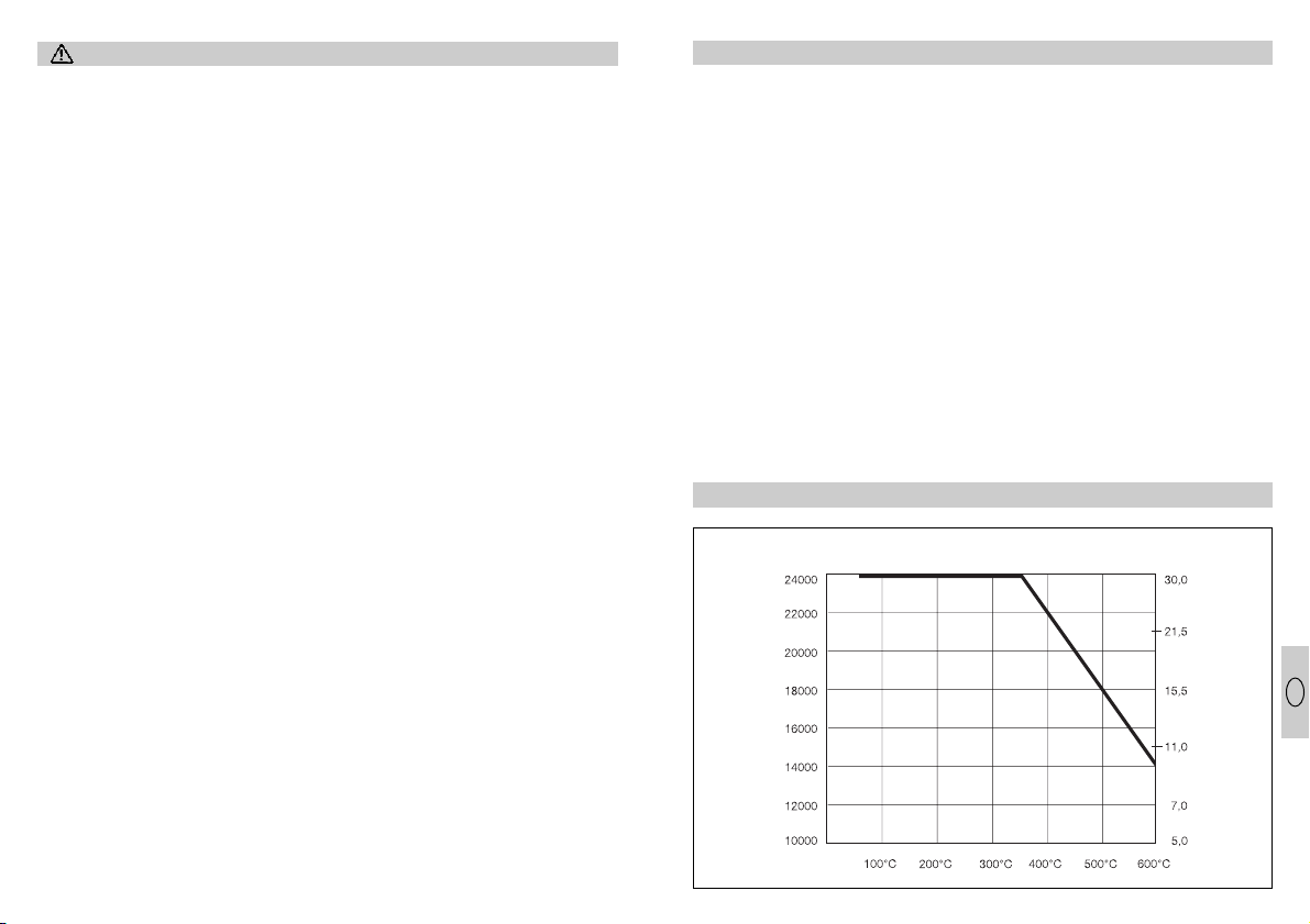
Sikkerhedsanvisning
OBS! Ved brug af el-værktøj
skal nedenstående grundlæggende sikkerhedsregler
overholdes for at forebygge
elektriske stød og risiko for
tilskadekomst og brand.
Læs denne vejledning
opmærksomt, før De bruger
apparatet.
y
Hvis apparatet ikke
behandles omhyggeligt,
kan der opstå brand.
y
Tag hensyn til følgende
påvirkninger fra omgivelserne.
–
Elektroapparater må ikke
udsættes for regn.
–
Brug ikke elektroværktøj i
fugtig tilstand og ikke i
fugtige eller våde omgivelser.
–
Vær forsigtig med apparaterne i nærheden af
brandbare materialer. Ret
dem ikke mod det samme
sted i længere tid.
–
Brug ikke apparatet i en
eksplosiv atmosfære.
–
Varme kan ledes til brandbare materialer, som er
dækket.
y
Beskyt Dem mod elektriske stød.
–
Undgå at berøre jordforbundne dele med kroppen, f. eks. rør, radiator,
komfur, køleskab.
y
Apparatet skal altid være
under opsyn, når det er
tændt.
y
Opbevar Deres værktøj
forsvarligt.
–
Efter brug lægges apparatet på stativet til afkøling,
inden det pakkes væk.
–
Ikke benyttet værktøj skal
opbevares i et tørt aflåst
rum og utilgængeligt for
børn.
y
Udsæt ikke Deres værktøj
for overbelastning.
–
De arbejder bedre og
mere sikkert indenfor det
angivne effektområde.
–
Efter længere tids brug
ved 600° C bør temperaturen sænkes inden apparatet slukkes. Det forlænger
varmeelementets levetid.
y
Vær opmærksom på giftige gasser og antændelsesfare.
–
Ved bearbejdning af
kunststoffer, lakker og lignende materialer kan der
udvikles giftige gasser.
Vær opmærksom på
brand- og antændelsesfare.
y
Brug ikke kablet forkert.
–
Bær aldrig værktøjet i
kablet og træk ikke i
kablet, når De skal tage
stikket ud af stikkontakten.
Beskyt kablet mod stærk
varme, olie og skarpe kanter.
y
OBS
–
Af hensyn til Deres egen
sikkerhed bør De kun
bruge tilbehør og ekstraapparater, som er beskrevet i brugsanvisningen
eller som er anbefalet og
angivet af værktøjs-producenten. Brug af tilbehør,
som ikke er anbefalet i
brugsanvisningen eller
kataloget kan for Dem personligt medføre risiko for
tilskadekomst.
y
Reparationer kun af
elektro-fagfolk.
–
Dette elektroværktøj lever
op til de almindelige sikkerhedsbestemmelser.
Reparationer må kun
udføres af elektro-fagfolk, i
modsat fald kan der opstå
uheld for brugeren.
y
Hvis brugsanvisningen
ikke overholdes kan
apparatet udgøre en kilde
til fare.
y
Opbevar sikkerhedsanvisningen godt.
Anvendelse
Apparatet tændes med
tænd-/sluk-kontakten .
Med temperaturregulatoren
indstilles den ønskede
temperatur (25° C–
600° C). Temperaturværdien
samt bogstavet „A” som
betegnelse for den valgte
modus vises i LED-segmentdisplayet. Når temperaturen
er valgt skifter apparatet
automatisk efter ca.
3 sekunder om til at vise
den faktiske temperatur.
Visningen af den ønskede
og den faktiske temperatur
sker i skridt på 10°C.
Luftmængden kan reguleres trinløst med luftstrømsregulatoren.
Styringen svarer til de
nyeste normer for strømtræk
(EN 61000-3-3 netstøjsnorm,
EN 61000-3-2 oversvingsningsnorm).
Apparatet er udstyret med
en intelligent temperatur- og
luftmængderegulering.
Denne giver hele tiden temperaturindstillingen forrang
(se diagrammet). Eksempel:
For at opnå den maksimale
temperatur på 600° C, ved
samtidig indstilling af
omdrejningstallet til maksimal lufttransport, regulerer
elektronikken automatisk
luftmængden så langt ned,
at de 600° C kan opnås.
Tilsvarende stiger luftmængden, så snart temperaturen
nedsættes.
Intelligent motor- og temperaturstyring
Intelligent motor- og temperaturstyring
Motorens
omdreijningstal
(omdr./min.)
Dyn. tryk
(hPa)
Udgangstemperatur
46 47
DK
Page 25

0202
1. Vigtigt! Adskil apparatet
fra lysnettet.
2. Skruerne løsnes og af-
dækningskappen
trækkes af.
3. Trækaflastningen løs-
nes.
4. Lysnetklemmerne løs-
nes.
5. Kablet trækkes ud.
6. Nyt kabel lægges ind og
gøres fast i omvendt rækkefølge (1. lysnetklemmer
skrues fast etc.).
0
Udskiftning af Varmeelement
Varmeelementet i
HG 4000 E og HG 5000 E er
stukket på og kan udskiftes
med få håndgreb.
Hvert varmeelement er
udstyret med en chip, som
indeholder dets specifikke
data. Når der indbygges et
1. Vigtigt! Adskil apparatet
fra lysnettet.
2. De 4 skruer ved enden af
udblæsningsrøret løsnes.
3. Varmeelementet trækkes
af og skiftes ud med et
nyt.
4. Udblæsningsrøret skrues
fast igen.
nyt varmeelement overtages
dets parametre af styreelektronikken.
Udskiftning af kabel
Tilbehør / anvendelseseksempler
Tilbehør HG 4000 E
Vinkel-bredstråledyse 40 x 2
Anvendelsesformål:
Svejsning af kunststoffolier i
overlappende svejseteknik.
Reparation af bitumentage.
Vinkel-bredstråledyse 20 x 2
Anvendelsesformål:
Svejsning af kunststoffolier i
overlappende svejseteknik.
Runddyse 5 mm
Anvendelsesformål:
Svejsning af kunststof.
Punktpræcis opvarmning.
Runddyse 10 mm
Anvendelsesformål:
Svejsning af kunststof.
Punktpræcis opvarmning.
Anvendelse med svejsesko.
Svejsesko
Anvendelsesformål: Kan
sættes på runddyse 10 mm.
Svejsning med kunststofsvejsetråd.
Tilbehør HG 5000 E
Bredstråledyse 70 x 10
Anvendelsesformål: Samling
af luftstrømmen.
Vinkel-bredstråledyse 74 x 3
Anvendelsesformål:
Svejsning af kunststoffolier i
overlappende svejseteknik.
Er lysnetkablet beskadiget,
kan det uden problemer
udskiftes uden at åbne huset.
b
c
a
b
c
d
a
d
48 49
DK
Page 26

Funktionsgaranti
Dette STEINEL-produkt er
fremstillet med største omhu,
afprøvet efter gældende forskrifter samt underlagt en
stikprøvekontrol.
Garantien gælder i 12 måneder fra den dag, apparatet
er solgt til forbrugeren. Ved
materiale- og fabrikationsfejl
ydes garantien gennem
reparation eller ombytning af
defekte dele efter vort valg.
Der ydes ikke garanti ved
skader på sliddele (f.eks.
varmeelement, lysnetkabel),
ej heller ved skader og fejl,
der er opstået pga. ukorrekt
behandling eller vedligeholdelse og heller ikke, hvis
apparatet er be-skadiget
pga. at det er blevet tabt.
Garantien omfatter ikke følgeskader på fremmede genstande.
Der ydes kun garanti mod
forevisning af bon eller kvittering (med dato og stempel). Derudover skal apparatet være helt og indpakket
forsvarligt, når det fremsendes til reparation på serviceværkstedet eller inden for de
første 6 måneder afleveres
til forhandleren.
Reparationsservice:
Efter garantitidens udløb
eller ved fejl, der ikke er
dækket af garantien, kan
apparatet repareres på vort
værksted. Sørg for, at produktet er indpakket forsvarligt under forsendelsen til
nærmeste serviceværksted.
Overensstemmelseserklæring
Produktet opfylder lavspændingsdirektivet
73/23/EØF og EMC-direktivet 89/336/EØF.
C
Hjælpeværktøj HG 4000 E / HG 5000 E
Trykrulle
Anvendelsesformål:
Fasttrykning af kantafslutninger, PVC-svejsefolie o.s.v.
Trykrolle til svysetråd
Anvendelsesformål:
Fasttrykning af svejsetråde.
50
2
2
0
Käyttöohje
Laitteen kuvaus
Kuumailmapuhaltimen ominaispiirteet
y
Täyselektroninen lämpötilan ja puhallusilman määrän säätö
y
Puhallusilman ja lämpötilan portaaton säätö
y
Älykäs moottorin ja lämpötilan ohjaus
y
Näytössä lämpötilan asetettu ja mitattu arvo
y
Lämmitin helposti vaihdettavissa
y
Harjaton moottori takaa pitkän käyttöiän
y
Tukeva yhdestä osasta koostuva runko
y
Verkkojohdon vaihto ilman kotelon avausta
Osat
Suuosa (HG 4000 E: 40 mm, HG 5000 E: 50 mm)
Lämmitin
Iskusuojus
LED-segmenttinäyttö
Lämpötilan säädin
Kytkin
Puhallusilman säädin
Tekniset tiedot
HG 4000 E HG 5000 E
Jännite: 100 V 110 V 230–240 V/50 Hz 230–240 V/50 Hz
Teho: 1500 W 1650 W 1750 W 3400 W
Lämpötila: 25–600° C, portaaton 25–600° C, portaaton
Näyttö: LED-segmenttinäyttö LE D-segmenttinäyttö
Puhallusilman säätö: portaaton portaaton
Puhallusilman määrä: maks. 600 l/min. maks. 800 l/min.
Ilmanpaine: 3000 Pa 3000 Pa
Suuosa: Ø 40 mm Ø 50 mm
Moottorin käyttöikä: n. 20 000 h n. 20000 h
Lämmittimen käyttöikä: n. 500–800 h n. 500–800 h
Verkkojohto: H07 RN-F 2 x 1 H07 RN-F 2 x 1,5
pituus: 2,5 m pituus: 2,5 m
Paino (ilman verkkojohtoa): 1115 g 1190 g
Mitat: Pituus: 370 mm Pituus: 350 mm
Ø 122 mm Ø 122 mm
(iskusuojuksen
(iskusuojuksen
kohdalla) kohdalla)
51
FIN
Page 27

Turvaohjeita
Huomio! Sähkötyökaluja
käytettäessä on sähköiskujen ja loukkaantumis- ja tulipalonvaaran vuoksi noudatettava seuraavia perusturvaohjeita. Lue ohjeet ennen
työskentelyn aloittamista.
y
Laitteen huolimattomasta
käytöstä saattaa olla seurauksena tulipalo.
y
Ota huomioon ympäristön
vaikutukset.
–
Älä jätä sähkötyökaluja
sateeseen.
–
Älä käytä sähkötyökaluja
märkänä äläkä kosteissa
tai märissä oloissa.
–
Noudata erityistä varovaisuutta käyttäessäsi laitetta
syttyvien materiaalien
läheisyydessä. Älä suuntaa laitetta pitkän aikaa
yhteen kohtaan.
–
Älä käytä laitetta jos olemassa on räjähdysvaara.
–
Lämpö saattaa kulkeutua
näkymättömissä oleviin
syttyviin materiaaleihin.
y
Ehkäise sähköiskut.
–
Vältä kosketusta maadoitettuihin osiin, kuten
putkiin, lämpöpattereihin,
liesiin ja jääkaappeihin.
y
Älä jätä laitetta ilman valvontaa, kun se on käytössä.
y
Säilytä työkalut turvallisessa paikassa.
–
Aseta laite käytön jälkeen
telineeseen ja anna sen
jäähtyä ennen kuin pakkaat sen pois.
–
Kun kone ei ole käytössä,
säilytä se kuivassa,
suljetussa tilassa poissa
lasten ulottuvilta.
y
Älä ylikuormita
työkalujasi.
–
Ne toimivat parhaiten ja
turvallisimmin ilmoitetulla
tehoalueella.
–
Jos laitetta on pitkään
käytetty 600°C lämpötilalla,
lämpötilaa tulisi alentaa
ennen laitteen sammuttamista. Tämä pidentää lämmittimen kestoaikaa.
y
Ota huomioon myrkylliset
kaasut ja syttymisvaara.
–
Käsiteltäessä muoveja,
lakkoja ja muita vastaavia
materiaaleja saattaa syntyä myrkyllisiä kaasuja.
Ota huomioon palo- ja
syttymisvaara.
y
Käsittele johtoa huolellisesti..
–
Älä kanna laitetta johdosta
äläkä irrota laitetta pistorasiasta johdosta
vetämällä. Suojaa johto
kuumuudelta, öljyltä ja
teräviltä kulmilta.
y
Huomio
–
Käytä oman turvallisuutesi
vuoksi vain käyttöohjeessa
mainittuja tai valmistajan
suosittelemia tai ilmoittamia tarvikkeita ja lisälaitteita. Muiden kuin käyttöohjeessa tai luettelossa
suositeltujen lisälaitteiden
tai tarvikkeiden käyttö
saattaa aiheuttaa turvallisuusriskejä.
y
Koneen saa korjata vain
sähköalan ammattilainen.
–
Tämä sähkötyökalu on
asiaankuuluvien turvallisuusmääräysten mukainen. Onnettomuuksien
välttämiseksi korjaukset
saa suorittaa vain sähköalan ammattilainen.
y
Käyttöohjeita on ehdottomasti noudatettava!
Muussa tapauksessa
laitteen käyttö saattaa
olla vaarallista.
y
Säilytä turvaohjeet huolellisesti.
Käyttöönotto
Käynnistä laite kytkimellä .
Valitse haluttu lämpötila
(25° C - 600° C) lämpötilan
säätimellä Valitsemasi
lämpötila sekä säätötilaa
osoittava kirjain "A" ilmestyvät LED-segmenttinäyttöön. Noin 3 sekunnin kuluttua lämpötilan valinnasta
laite osoittaa automaattisesti
todellisen lämpötilan. Valittu
lämpötila ja todellinen
lämpötila näkyvät porrastetusti 10°C:n välein.
Puhallusilman määrä voidaan säätää portaattomasti
säätimellä .
Säätö on verkkohäiriöitä
koskevien uusimpien standardien mukainen (EN
61000-3-3 Välkyntäjännite,
EN 61000-3-2 Yliaallot).
Laitteen älykäs lämpötilan ja
ilmamäärän säätö asettaa
aina valitun lämpötilan etusijalle (katso diagrammia).
Esimerkki: Jotta saavutetaan
600°C maksimilämpötila kun
pyörimisnopeus on samanaikaisesti asetettu maksimaaliselle puhallusilmalle,
laitteen elektroniikka säätää
ilmamäärän automaattisesti
niin pieneksi, että saavutetaan 600°C lämpötila.
Vastaavasti ilmamäärä suurenee jälleen kun lämpötila
alenee.
Älykäs moottorin ja lämpötilan säätö
Älykäs moottorin ja lämpötilan säätö
Moottorin
kierrosluku
(rpm)
Dyn. paine
(hPa)
Puhallusilman lämpötila
52 53
FIN
Page 28

0202
1. Tärkeää! Irrota laite
verkosta.
2. Irrota ruuvit ja vedä suoja-
levy irti.
3. Irrota vedonpoistin .
4. Irrota liittimet .
5. Vedä johto irti.
6. Aseta uusi johto paikal-
leen ja kiinnitä osat takaisin vastakkaisessa järjestyksessä (1. kiristä liittimet
jne.).
0
Lämmittimen vaihto
HG 4000 E:n ja HG 5000
E:n lämmitin on helppo kiinnittää paikalleen ja sen
vaihto sujuu vaivatta.
Jokaisessa lämmittimessä
on sille ominaisia tietoja
sisältävä chip. Kun asennetaan uusi lämmitin,
1. Tärkeää! Irrota laite
verkosta.
2. Irrota suuosan päässä
olevat 4 ruuvia.
3. Vedä lämmitin irti ja
vaihda uusi tilalle.
4. Kierrä suuosa jälleen
kiinni.
säätöelektroniikka omaksuu
uudet parametrit.
Johdon vaihtaminen
Tarvikkeet / käyttöesimerkkejä
Tarvikkeet HG 4000 E
Litteä suutin, taivutettu
40 x 2
Käyttö: Muovikalvojen limi-
hitsaus. Bitumikattohuovan
korjaustyöt.
Litteä suutin, taivutettu
20 x 2
Käyttö: Muovikalvojen
limihitsaus.
Pyöreä suutin 5 mm
Käyttö: Muovin hitsaaminen.
Kohdetarkka kuumennus.
Pyöreä suutin 10 mm
Käyttö: Muovin hitsaaminen.
Kohdetarkka kuumennus.
Käyttö hitsaussuulakkeen
kanssa.
Hitsaussuulake
Käyttö: Pujotetaan pyöreään
suuttimeen (10 mm). Hitsaus
muovihitsauslangalla.
Tarvikkeet HG 5000 E
Litteä suutin 70 x 10
Käyttö: Ilmavirran kohdistus.
Litteä suutin, taivutettu
74 x 3
Käyttö: Muovikalvojen
limihitsaus.
Vahingoittunut verkkojohto
voidaan vaihtaa vaivatto-
masti koteloa avaamatta.
b
c
a
b
c
d
a
d
54 55
FIN
Page 29

Toimintatakuu
Tämä Steinel-tuote on valmistettu suurella tarkkuudella ja sen toiminta ja turvallisuus on testattu voimassa
olevien määräysten mukaisesti. Lisäksi sille on suoritettu pistokoe.
Takuuaika on 12 kuukautta
tai ostopäivästä alkaen. Tänä
aikana Steinel vastaa kaikista aine- ja valmistusvioista
valintansa mukaan joko korjaamalla tai vaihtamalla vialliset osat. Takuun piiriin eivät
kuulu kuluvat osat kuten
esim. kuumennusosat ja
verkkojohto eivätkä vahingot,
jotka ovat aiheutuneet
väärästä käytöstä tai huollosta tai laitteen pudottamisesta.
Takuu ei koske laitteen muille esineille mahdollisesti
aiheuttamia vahinkoja.
Takuu on voimassa vain silloin, jos laitetta ei ole itse
avattu ja se toimitetaan
yhdessä ostokuitin tai laskun kanssa (ostopäivämäärä
ja myyjäliikkeen leima) hyvin
pakattuna lähimpään huoltopisteeseen tai ensimmäisten 6 kuukauden aikana
myyjäliikkeeseen.
Korjauspalvelu:
Takuuajan jälkeen tai takuun
piiriin kuulumattoman vian
ollessa kyseessä laitteen
korjaa huoltopalvelumme.
Pyydämme lähettämään
tuotteen hyvin pakattuna
lähimpään huoltopisteeseen.
Selvitys -yhdenmukaisuudesta
Laite on pienjännitedirektiivin
73/23/EY ja EMC-direktiivin
89/336/EY vaatimusten
mukainen.
C
Apuvälineet HG 4000 E / HG 5000 E
Painorulla
Käyttö: Reunasuojusten,
PVC-hitsauskalvojen jne.
painaminen.
Hitsauslangan painorulla
Käyttö: Hitsauslangan
painaminen.
56
2
2
0
Bruksanvisning
Beskrivelse av apparatet
Varmluftpistol - spesifikasjoner
y
Helelektronisk regulering av temperatur og luftmengde
y
Luftmengde og temperatur kan innstilles trinnløst
y
Intelligent styring av motor og temperatur
y
Display med nominell og faktisk verdi
y
Varmeelementet kan lett skiftes ut
y
Motor uten børster garanterer lang levetid
y
Stabilt hus i en del
y
Ledningen kan skiftes ut uten at huset må åpnes
Komponenter
Utblåsningsrør (HG 4000 E: 40 mm, HG 5000 E: 50 mm)
Varmeelement
Støtdemper
LED-segmentdisplay
Temperaturvelger
INN-/ UT-bryter for inn- og utkobling
Luftstrømregulator
Tekniske data
HG 4000 E HG 5000 E
Spenning: 100 V 110 V 230–240 V/50 Hz 230–240 V/50 Hz
Ytelse: 1500 W 1650 W 1750 W 3400 W
Temperatur: 25–600° C, trinnløs 25–600°C, trinnløs
Displaytype: LED-segmentdisplay LED-segmentdisplay
Luftmengderegulering: trinnløs trinnløs
Luftmengde: maks. 600 l/min. maks. 800 l/min.
Lufttrykk: 3000 Pa 3000 Pa
Utblåsningsrør: Ø 40 mm Ø 50 mm
Levetid, motor: ca. 20000 timer ca. 20 000 timer
Levetid, varmeelement: ca. 500–800 timer ca. 500–800 timer
Ledning: H07 RN-F 2 x 1 H07 RN-F 2 x 1,5
lengde: 2,5 m lengde: 2,5 m
Vekt (uten ledning): 1115 g 1190 g
Mål: Lengde: 370 mm Lengde: 350 mm
Ø 122 mm Ø 122 mm
(ved støtdemperen ) (ved støtdemperen )
57
N
N
Page 30

Sikkerhetsmerknader
Forsiktig! Ved bruk av elek-
trisk verktøy gjelder følgende generelle forholdsregler
vedrørende sikkerhet.
Reglera har som formål å
beskytte brukeren mot elektrisk støt og mot fare for
skade og brann. Les derfor
følgende merknader nøye
før apparatet tas i bruk.
y
Hvis en ikke omgås apparatet med omhu kan det
oppstå brann.
y
Ta hensyn til påvirkninger
fra omgivelsene.
–
Utsett ikke apparatet for
regn.
–
Bruk ikke elektroverktøy
når det er fuktig eller fuktige eller våte omgivelser.
–
Vær forsiktig ved bruk av
apparatene i nærheten av
brennbare materialer. Rett
ikke apparatet mot ett og
samme sted i lengre tid.
–
Benytt ikke apparatet i en
eksplosjonsfarlig atmosfære.
–
Varmen kan ledes videre
til skjulte, brennbare materialer.
y
Beskytt deg selv mot
elektrisk støt.
–
Unngå kroppskontakt med
jordete deler, f.eks rør,
radiatorer, komfyrer og
kjøleskap.
y
La ikke apparatet være
uten oppsyn når det er
slått på
y
Oppbevar verktøyet ditt
på en sikker måte.
–
sett apparatet på stativet
etter bruk og la det kjøles
ned før det pakkes bort.
–
Verktøy som ikke benyttes
bør oppbevares i tørre og
låste rom utilgjengelig for
barn.
y
Sørg for at verktøyet ikke
overbelastes.
–
En arbeider bedre og sikrere i det angitte ytelsesområde.
–
Etter lengre bruk av apparatet ved 600°C bør temperaturen senkes før
apparatet kobles ut. Dette
forlenger varmeelementets
levetid.
y
Vær oppmerksom på giftige gasser og fare for
antennelse.
–
Ved arbeid med plast, lakk
og lignende materialer kan
det oppstå giftige gasser.
Vær oppmerksom på
antennelses- og brannfaren.
y
Bruk ledningen kun i henhold til formålet.
–
Bær ikke verktøyet etter
ledningen og benytt ikke
ledningen til å trekke støpselet ut av stikkontakten.
Beskytt ledningen mot
varme, olje og skarpe kanter.
y
Forsiktig
–
For din egen sikkerhets
skyld bør du kun benytte
tilbehør og tilleggsutstyr
som er oppført i bruksanvisningen eller som er
anbefalt eller angitt av
produsenten av verktøyet.
Bruk av annet verktøy eller
tilbehør enn det som er
anbefalt i bruksanvisningen eller katalogen kan
medføre risiko for at du
selv kan komme til skade.
y
Reparasjoner kun av
elektrofagmannen.
–
Dette elektroverktøyet tilsvarer sikkerhetsbestemmelsene for slikt verktøy.
Reparasjoner skal kun
utføres av en elektro-fagmann, da fare for brukeren
ellers kan oppstå.
y
Hvis henvisningene i
bruksanvisningen ikke
følges kan apparatet bli til
en farekilde.
y
Oppbevar sikkerhetsmerknadene godt.
Igangsetting
Apparatet innkobles med
INN-/ UT-bryteren .
Den ønskede temperatur
forvelges med temperaturvelgeren (mellom 25°C og
600°C). Temperaturen og
bokstaven «A» som kjennetegner innstillingsmodus
vises i LFD segment-displayet. Etter at temperaturen
blir forvalgt sjalter apparatet
etter ca. 3 sekunder automatisk om til å vise faktisk
verdi. Temperaturen verdiene
vises i trinn på 10°C.
Luftmengden kan reguleres trinnløst med luftstrømregulatoren.
Reguleringen tilsvarer de
nyeste normer vedrørende
tilbakevirkning på det
matende nettet (EN 610003-3 norm vedr. spenningsfluktuasjoner og flimmer og
EN 61000-3-2 norm vedr.
harmoniske strømmer).
Apparatet har en intelligent
regulering av temperatur og
luftmengde. Reguleringen gir
alltid temperaturinnstillingen
forrang (se diagram-met). Et
eksempel: For å nå den
maksimale temperatur på
600°C, ved samtidig innstilling av turtallet på maksimal
luftmengde, sørger elektronikken for at luftmengden
reduseres inntil de 600°C er
nådd. Luftmengden økes
tilsvarende igjen straks temperaturen senkes.
Intelligent motor- og temperaturstyring
Intelligent motor- og temperaturstyring
Motorens
turtall
(rpm)
Dyn. tryck
(hPa)
Utgangstemperatur
58 59
N
Page 31

0202
1. Viktig! Trekk støpslet ut
av stikkontakten.
2. Løs skruene og dra bes-
kyttelseshetten av.
3. Løs strekkavlastningen
.
4. Løs nettklemmene .
5. Trekk ut ledningen .
6. Legg inn ny ledning og
fest den igjen i omvendt
rekkefølge av skrittene
ovenfor (1. Fest nettklemmene etc.).
0
Utskifting av varmeelementet
Varmeelementet i HG 4000 E
og HG 5000 E kan skiftes ut
med få håndgrep.
Hvert varmeelement inneholder en chip med dets
individuelle data. Når et nytt
varmeelement innbygges,
1. Viktig! Trekk støpslet ut
av stikkontakten.
2. Løs de 4 skruene ved
enden av utblåsningsrøret.
3. Trekk varmeelementet ut
og sett inn et nytt element.
4. Skru utblåsningsrøret fast
igjen.
overtar reguleringselektronikken parameterne til det
nye elementet
Utskifting av ledning
Tilbehør / Eksempler på anvendelsen av det
Tilbehør for HG 4000 E
Vinkel-flatdyse 40 x 2
Anvendelse:
Overlappsveising av plast.
Reparasjoner av bitumentak.
Vinkel-flatdyse 20 x 2
Anvendelse:
Overlappsveising av plast.
Runddyse 5 mm
Anvendelse: Sveising av
plast. Presis oppvarming
av små flater.
Runddyse 10 mm
Anvendelse: Sveising av
plast. Presis oppvarming av
små flater. Benyttes med
sveisesko.
Sveisesko
Anvendelse: Settes på
runddyse 10 mm.
Sveising med plastsveise-
tråd.
Tilbehør for HG 5000 E
Flatdyse 70 x 10
Anvendelse: Samling av
luftstrømmen.
Vinkel-flatdyse 74 x 3
Anvendelse:
Overlappsveising av plast.
Hvis ledningen er skadet
kan den skiftes ut uten
problemer, og uten at huset må
åpnes.
b
c
a
b
c
d
a
60 61
N
d
Page 32

Funksjonsgaranti
Dette STEINEL-produktet er
fremstilt med største nøyaktighet og er blitt funksjonsog sikkerhetstestet i hht.
gjeldende forskrifter, og
deretter underkastet en
stikkprøvekontroll.
Garantitiden er 12 måneder
og beregnes fra salgsdagen
til forbrukeren. Vi erstatter
alle mangler som skyldes
materiale- eller fabrikasjonsfeil. Garantiordningen skjer
enten ved at feilene utbedres eller at delene byttes ut.
Garantien bortfaller ved skader på slitasjedeler, som
f.eks. varmeelement og nettkabel eller ved skader eller
mangler som oppstår som
følge av ufagmessig bruk
eller vedlikehold, og ved
bruddskader som skyldes at
apparatet har falt ned.
Følgeskader på fremmede
gjenstander er utelukket fra
garantiordningen.
Garantien gjelder kun dersom apparatet, som ikke må
være demontert, sendes i
godt innpakket stand sammen med kassakvitteringen
eller regningen (kjøpsdato
og forhandlerstempel) til vårt
servicested, eller overleveres
forhandleren innen de første
6 månedene.
Reparasjonsservice:
Etter garantitidens utløp eller
ved mangler uten garantiansvar, repareres apparatet
på vårt verksted. Vennligst
send produktet godt innpakket til Deres nærmeste
serviceverksted.
Konformitetserklæring
Produktet oppfyller lavspenningsretningslinjen
73/23/EWG og EMV-retningslinjen 89/336/EWG.
C
Hjelpmemidler for HG 4000 E / HG 5000 E
Påtrykningsrull
Anvendelse: Brukes ved
foliering av kanter og ved
sveising av plastfolier.
Påtrykningsrull for sveisetråd
Anvendelse: Trykke ned
sveisetråd.
62
 Loading...