

Page 1

Plug-in Reference
Page 2

Original manual by Anders Nordmark
Revision: Cristina Bachmann, Heiko Bischoff, Marion Bröer, Sabine Pfeifer
The information in this document is subject to change without notice and does not represent a commitment on the part
of Steinberg Media Technologies GmbH. The software described by this document is subject to a License Agreement
and may not be copied to other media except as specifically allowed in the License Agreement. No part of this publication may be copied, reproduced or otherwise transmitted or recorded, for any purpose, without prior written permission
by Steinberg Media Technologies GmbH.
All product and company names are ™ or ® trademarks of their respective owners. Windows XP is a trademark of
Microsoft Corporation. Windows Vista is either a registered trademark or trademark of Microsoft Corporation in the
United States and/or other countries. The Mac logo is a trademark used under license. Macintosh and Power Macintosh
are registered trademarks.
Release Date: October 19, 2007
© Steinberg Media Technologies GmbH, 2007.
All rights reserved.
Page 3

Table of Contents
Page 4

5 The included effect plug-ins
6 Introduction
6 Delay plug-ins
9 Distortion plug-ins
10 Dynamics plug-ins
19 EQ plug-ins
21 Filter plug-ins
25 Mastering – UV 22 HR (Cubase only)
25 Modulation plug-ins
32 Other plug-ins
34 Restoration plug-ins
34 Reverb plug-ins
36 Spatial plug-ins
37 Surround plug-ins (Cubase only)
37 Tools plug-ins
41 The included VST Instruments
42 Introduction
42 Prologue
42 Sound parameters
47 Modulation and controllers
52 Spector (Cubase only)
52 Sound parameters
54 Modulation and controllers
60 Mystic (Cubase only)
60 Sound parameters
62 Modulation and controllers
67 HALionOne
69 Embracer – Surround Pad Synthesizer
(Cubase only)
71 Monologue – Monophonic Analog Modeling
Synthesizer (Cubase only)
73 Diagrams
75 MIDI effects
76 Introduction
76 Arpache 5
77 Arpache SX
78 Autopan
79 Chorder
80 Compress
81 Context Gate
82 Density
82 Micro Tuner
82 MIDIControl
83 MIDIEcho
84 Note to CC
85 Quantizer
85 Step Designer
87 Track Control
89 Track FX
89 Transformer
90 Index
4
Table of Contents
Page 5

1
The included effect plug-ins
Page 6
Introduction
This chapter contains descriptions of the included plug-in
effects and their parameters.
In Cubase, the plug-in effects are arranged in a number of
different categories. This chapter is arranged in the same
fashion, with the plug-ins listed in separate sections for
each effect category.
Ö Most of the included effects are compatible with
VST3, this is indicated by an icon in front of the name of
the plug-in as displayed in plug-in selection menus (for
further information, see the chapter “Audio Effects” in the
Operation Manual).
Delay plug-ins
This section contains descriptions of the plug-ins in the
“Delay” category.
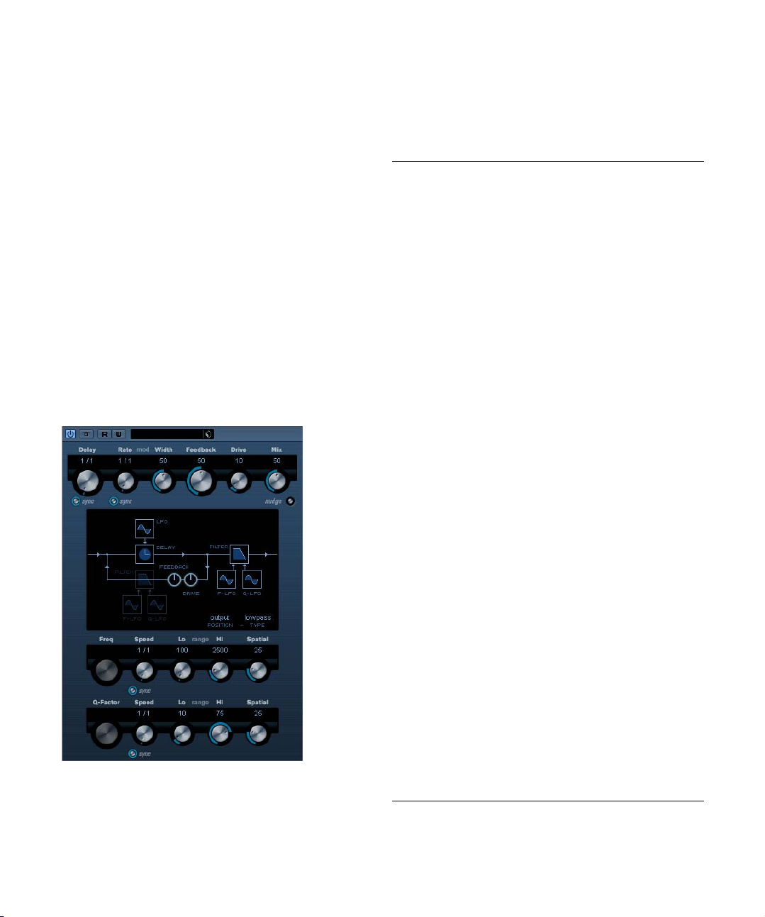
ModMachine (Cubase only)
ModMachine combines delay modulation and filter frequency/resonance modulation and can provide many interesting modulation effects. It also features a Drive
parameter for distortion effects.
The parameters are as follows:
Parameter Description
Delay This is where you specify the base note value for the de-
Tempo sync
Delay on/off
Rate The Rate parameter sets the base note value for tempo
Tempo sync
Rate on/off
Width This sets the amount of delay pitch modulation. Note that
Feedback This sets the number of repeats for the delay.
Drive This parameter adds distortion to the feeback loop. The
Mix Sets the level balance between the dry signal and the ef-
Nudge Clicking the Nudge button once will momentarily speed
Signal path
graphic
Output/Loop The Filter can either be placed in the feedback loop of the
Filter type This toggle button allows you to select a filter type. Low-
Freq This sets the cutoff frequency for the filter. This is avail-
Speed This sets the speed of the filter frequency LFO modula-
lay if tempo sync is on (1/1–1/32, straight, triplet or dotted). If tempo sync is off, the delay time can be set freely
in milliseconds.
The button below the Delay knob turns tempo sync for
the delay parameter on or off. If set to off, the delay time
can be set freely with the Delay knob.
syncing the delay modulation (1/1 to 1/32, straight, triplet
or dotted).
If tempo sync is off, the rate can be set freely with the
Rate knob.
The button below the Rate knob turns tempo sync for the
rate parameter on or off. If set to off, the rate can be set
freely with the Rate knob.
although the modulation affects the delay time, the sound
is mostly perceived as a vibrato or chorus-like effect.
longer the Feedback, the more the delay repeats become
distorted over time.
fect. If ModMachine is used as a send effect, this should
be set to maximum (100%) as you can control the dry/effect balance with the send.
up the audio coming into the plug-in, simulating an analog tape nudge type sound effect.
You can click on the Filter sections displayed in the
graphic in the center of the plug-in to place the Filter section either before or after the Drive and Feedback parameters in the signal path.
delay or in its output path (see above).
pass/bandpass/hipass filter types are available.
able only, if filter frequency LFO tempo sync is deactivated and the Speed parameter (see below) is set to “0".
tion. If tempo sync is activated the Speed parameter sets
the base note value for tempo syncing the modulation (1/
1 to 1/32, straight, triplet or dotted).
If tempo sync is off, the rate can be set freely with the
Speed knob.
6
The included effect plug-ins
Page 7
Parameter Description
Range Lo/Hi These knobs specify the range (in Hz) of the filter fre-
Spatial This introduces an offset between the channels to create
Q-Factor This controls the resonance of the filter. This is available
Speed This sets the speed of the filter resonance LFO modula-
Range Lo/Hi These knobs specify the range of filter resonance modu-
Spatial This introduces an offset between the channels to create
quency modulation. Both positive (e.g. Lo set to 50 and Hi
set to 10000) and negative (e.g. Lo set to 5000 and Hi set
to 500) ranges can be set. If tempo sync is off and the
Speed is set to zero, these parameters are inactive and the
filter frequency is instead controlled by the Freq parameter.
a stereo panorama effect for the filter frequency modulation. Turn clockwise for a more pronounced stereo effect.
only, if filter resonance LFO tempo sync is deactivated
and the Speed parameter (see below) is set to “0". If
tempo sync is on, the resonance is controlled by the
Speed and Range parameters.
tion. If tempo sync is activated, the Speed parameter sets
the base note value for tempo syncing the modulation (1/1
to 1/32, straight, triplet or dotted).
If tempo sync is off, the rate can be set freely with the
Speed knob.
lation. Both positive (e.g. Lo set to 50 and Hi set to 100)
and negative (e.g. Lo set to 100 and Hi set to 50) ranges
can be set. If tempo sync is off and the Speed is set to
zero, these parameters are inactive and the filter resonance is controlled by the Q-Factor parameter instead.
a stereo panorama effect for the filter resonance modulation. Turn clockwise for a more pronounced stereo effect.
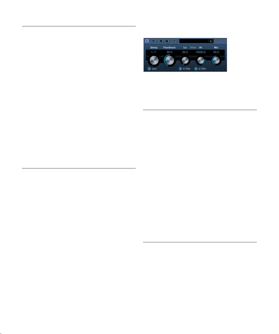
MonoDelay
This is a mono delay effect that can either be tempo-based
or use freely specified delay time settings. The delay can
also be controlled from another signal source via the SideChain input.
The parameters are as follows:
Parameter Description
Delay This is where you specify the base note value for the delay
Tempo sync
on/off
Feedback This sets the number of repeats for the delay.
Filter Lo This filter affects the feedback loop of the effect signal
Filter Hi This filter affects the feedback loop of the effect signal
Mix Sets the level balance between the dry signal and the ef-
Side-Chain
on/off
if tempo sync is on (1/1–1/32, straight, triplet or dotted). If
tempo sync is off, it sets the delay time in milliseconds.
The button below the Delay Time knob is used to turn
tempo sync on or off. If set to off, the delay time can be set
freely with the Delay Time knob, without sync to tempo.
and allows you to roll off low frequencies from 10Hz up
to 800Hz. The button below the knob activates/deactivates the filter.
and allows you to roll off high frequencies from 20kHz
down to 1.2kHz. The button below the knob activates/
deactivates the filter.
fect. If MonoDelay is used as a send effect, this should be
set to maximum as you can control the dry/effect balance
with the send.
When this is activated, the delay can be controlled by a
signal routed to the Side-Chain input. When the sidechain signal exceeds the threshhold the delay repeats are
silenced. When the signal drops below the threshold the
delay repeats reappear. For a description of how to set
up Side-Chain routing, see the chapter “Audio effects” in
the Operation Manual.
7
The included effect plug-ins
Page 8
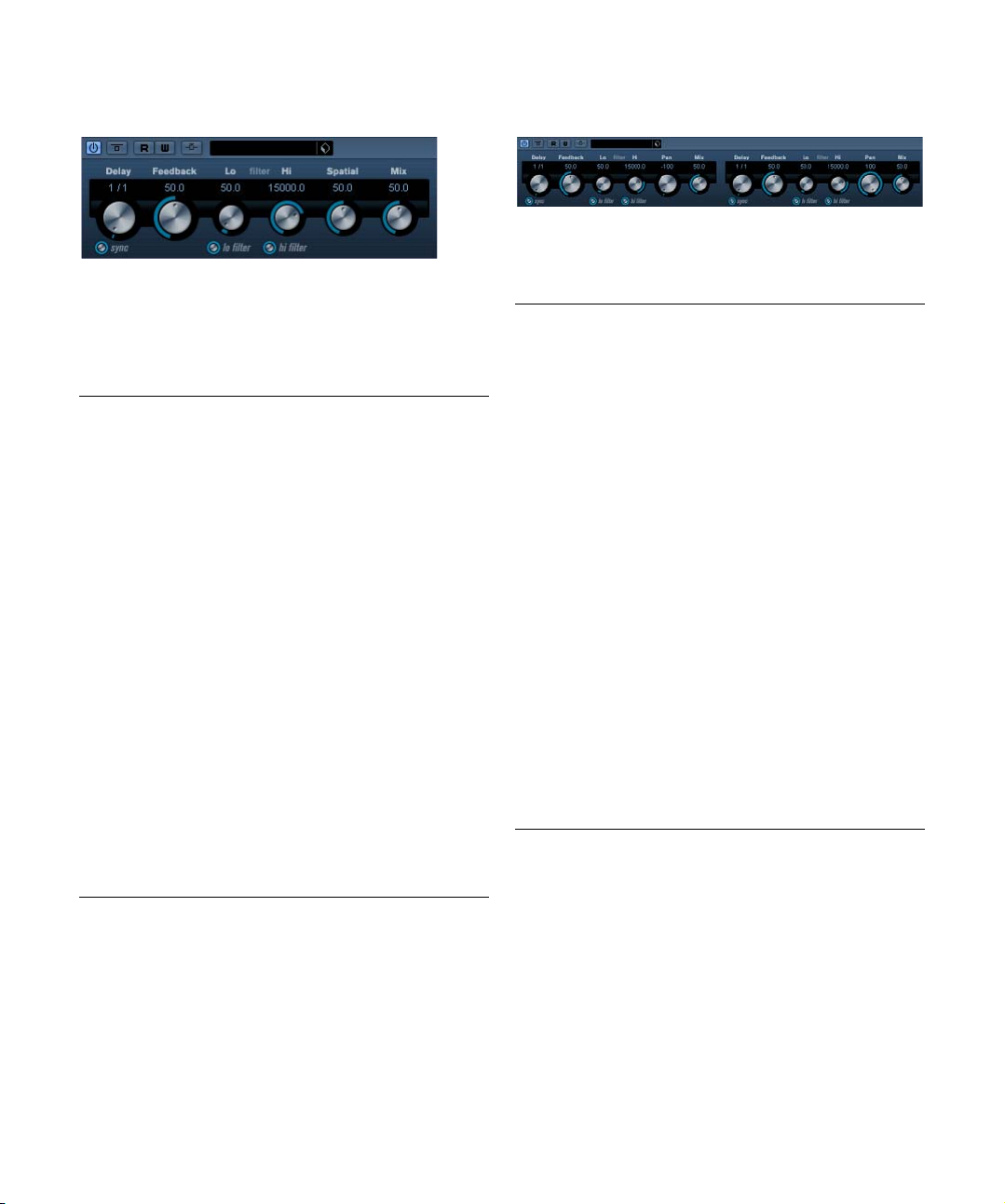
PingPongDelay
This is a stereo delay effect that alternates each delay repeat between the left and right channels. The effect can
either be tempo-based or use freely specified delay time
settings.
The parameters are as follows:
Parameter Description
Delay This is where you specify the base note value for the delay
Tempo sync
on/off
Feedback This sets the number of repeats for the delay.
Filter Lo This filter affects the feedback loop and allows you to roll
Filter Hi This filter affects the feedback loop and allows you to roll
Spatial This parameter sets the stereo width for the left/right re-
Mix Sets the level balance between the dry signal and the ef-
Side-Chain
on/off
if tempo sync is on (1/1–1/32, straight, triplet or dotted). If
tempo sync is off, it sets the delay time in milliseconds.
The button below the Delay Time knob is used to turn
tempo sync on or off. If set to off, the delay time can be set
freely with the Delay Time knob, without sync to tempo.
off low frequencies up to 800 Hz. The button below the
knob activates/deactivates the filter.
off high frequencies from 20kHz down to 1.2kHz. The
button below the knob activates/deactivates the filter.
peats. Turn clockwise for a more pronounced stereo
“ping-pong” effect.
fect. If PingPongDelay is used as a send effect, this
should be set to maximum as you can control the dry/effect balance with the send.
When this is activated, the delay can be controlled by a
signal routed to the Side-Chain input. When the sidechain signal exceeds the threshhold, the delay repeats are
silenced. When the signal drops below the threshold, the
delay repeats reappear. For a description of how to set up
Side-Chain routing, see the chapter “Audio effects” in the
Operation Manual.
StereoDelay
StereoDelay has two independent delay lines which either
use tempo-based or freely specified delay time settings.
The parameters are as follows:
Parameter Description
Delay 1 This is where you specify the base note value for the delay,
Delay 2 As above.
Tempo sync
on/off
Feedback
1 & 2
Filter Lo This filter affects the feedback loop and allows you to roll
Filter Hi This filter affects the feedback loop and allows you to roll
Pan1 & 2 This sets the stereo position for each delay.
Mix Sets the level balance between the dry signal and the ef-
Side-Chain
on/off
if tempo sync is on (1/1–1/32, straight, triplet or dotted). If
tempo sync is off, it sets the delay time in milliseconds.
The buttons below each respective Delay knob are used
to turn tempo sync on or off for the respective delay. If set
to off, the delay time can be set freely with the Delay Time
knobs.
This sets the number of repeats for each delay.
off low frequencies up to 800Hz. The button below the
knob activates/deactivates the filter.
off high frequencies from 20kHz down to 1.2kHz. The
button below the knob activates/deactivates the filter.
fect. If StereoDelay is used as a send effect, this should
be set to maximum (100%) as you can control the dry/effect balance with the send.
When this is activated, the delay can be controlled by a
signal routed to the Side-Chain input. When the sidechain signal exceeds the threshhold, the delay repeats
are silenced. When the signal drops below the threshold,
the delay repeats reappear. For a description of how to
set up Side-Chain routing, see the chapter “Audio effects” in the Operation Manual.
8
The included effect plug-ins
Page 9
Distortion plug-ins
This section contains descriptions of the plug-ins in the
“Distortion” category.
AmpSimulator
AmpSimulator is a distortion effect, emulating the sound
of various types of guitar amp and speaker cabinet combinations. A wide selection of amp and cabinet models is
available.
The parameters are as follows:
Parameter Description
Drive Governs the amount of amp overdrive.
Bass Tone control for the low frequencies.
Middle Tone control for the mid frequencies.
Treble Tone control for the high frequencies.
Presence Use this to boost or damp the higher frequencies.
Volume This controls the overall output level.
Amplifier This allows you to select between various amplifier mod-
Cabinet Various speaker cabinet models. Click on the currently
Damping Lo/Hi Further tone controls for shaping the sound of the se-
els. Click on the currently selected amplifier name to
open a pop-up with all the available amplifier models.
This section can be bypassed by selecting “No Amp".
selected cabinet name to open a pop-up with all the
available amplifier models.This section can be bypassed
by selecting “No Speaker".
lected speaker cabinet. Click on the values, enter a new
value and press the [Enter] key.
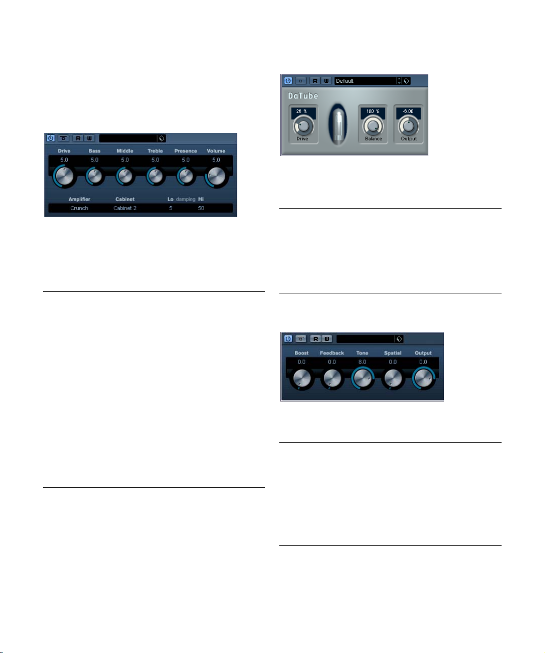
DaTube
This effect emulates the characteristic warm, lush sound
of a tube amplifier.
The parameters are as follows:
Parameter Description
Drive Regulates the pre-gain of the “amplifier”. Use high values
Balance This controls the balance between the signal processed
Output Adjusts the post-gain, or output level, of the “amplifier”.
if you want an overdriven sound just on the verge of
distortion.
by the Drive parameter and the dry input signal. For maximum drive effect, set this to its highest value.
Distortion
Distortion will add crunch to your tracks.
The parameters are as follows:
Parameter Description
Drive Increases the distortion amount.
Feedback This parameter feeds part of the output signal back to the
Tone Lets you select a frequency range to which to apply the
Spatial Changes the distortion characteristics of the left and
Output Raises or lowers the signal going out of the effect.
effect input, increasing the distortion effect.
distortion effect.
right channel, thus creating a stereo effect.
9
The included effect plug-ins
Page 10
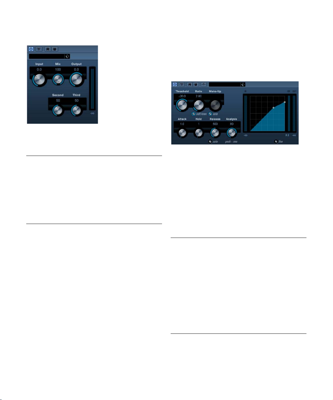
SoftClipper (Cubase only)
This effect adds soft overdrive, with independent control
over the second and third harmonic.
The parameters are as follows:
Parameter Description
Input Regulates the pre-gain. Use high values if you want an
Mix Setting Mix to 0 means that no processed signal is added
Output Adjusts the post-gain, or output level.
Second This allows you to adjust the amount of the second har-
Third This allows you to adjust the amount of the third harmonic
overdriven sound just on the verge of distortion.
to the original signal.
monic in the processed signal.
in the processed signal.
Dynamics plug-ins
This section contains descriptions of the plug-ins in the
“Dynamics” category.
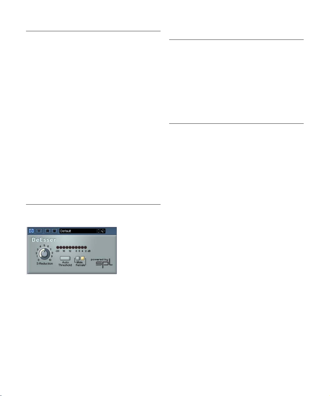
Compressor
Compressor reduces the dynamic range of the audio,
making softer sounds louder or louder sounds softer, or
both. Compressor features separate controls for threshold, ratio, attack, hold, release and make-up gain parameters. Compressor features a separate display that
graphically illustrates the compressor curve shaped according to the Threshold and Ratio parameter settings.
Compressor also features a Gain Reduction meter that
shows the amount of gain reduction in dB, Soft knee/Hard
knee compression modes and a program-dependent Auto
feature for the Release parameter.
The available parameters work as follows:
Parameter Description
Threshold
(-60 to 0dB)
Ratio
(1:1 to 8:1)
Soft Knee
(On/Off)
Make-up
(0–24dB or
“Auto mode")
This setting determines the level where Compressor “kicks
in”. Signal levels above the set threshold are affected, but
signal levels below are not processed.
Ratio determines the amount of gain reduction applied to
signals over the set threshold. A ratio of 3:1 means that for
every 3dB the input level increases, the output level will increase by only 1 dB.
If this is off, signals above the threshold will be compressed
instantly according to the set ratio (hard knee). When Soft
Knee is activated, the onset of compression will be more
gradual, producing a less drastic result.
This parameter is used to compensate for output gain loss,
caused by compression. If the Auto button is activated, the
knob becomes dark and the output is instead automatically
adjusted for gain loss.
10
The included effect plug-ins
Page 11
Parameter Description
Attack
(0.1–100ms)
Hold (0–
2000ms)
Release (10–
1000ms or
“Auto mode”)
Analysis
(0–100)
(Pure Peak to
Pure RMS)
Live mode
(On/Off)
Side-Chain
(On/Off)
This determines how fast Compressor will respond to signals above the set threshold. If the attack time is long, more
of the early part of the signal (attack) will pass through unprocessed.
Sets the time the applied compression will affect the signal
after exceeding the Threshold.
Sets the amount of time it takes for the gain to return to its
original level when the signal drops below the Threshold
level. If the “Auto” button is activated, Compressor will automatically find an optimal release setting that varies depending on the audio material.
This parameter determines whether the input signal is analysed according to peak or RMS values (or a mixture of
both). A value of 0 is pure peak and 100 pure RMS. RMS
mode operates using the average power of the audio signal
as a basis, whereas Peak mode operates more on peak levels. As a general guideline, RMS mode works better on material with few transients such as vocals, and Peak mode
better for percussive material, with a lot of transient peaks.
When activated, Live mode disengages the “look ahead”
feature of the Compressor. Look ahead does produce
more accurate processing but will add a certain amount of
latency as a trade-off. When Live mode is activated, there
is no latency, which might be better for “live” processing.
When this is activated, the compression can be controlled
by a signal routed to the Side-Chain input. When the sidechain signal exceeds the threshhold, the compression is
triggered. For a description of how to set up Side-Chain
routing, see the chapter “Audio effects” in the Operation
Manual.
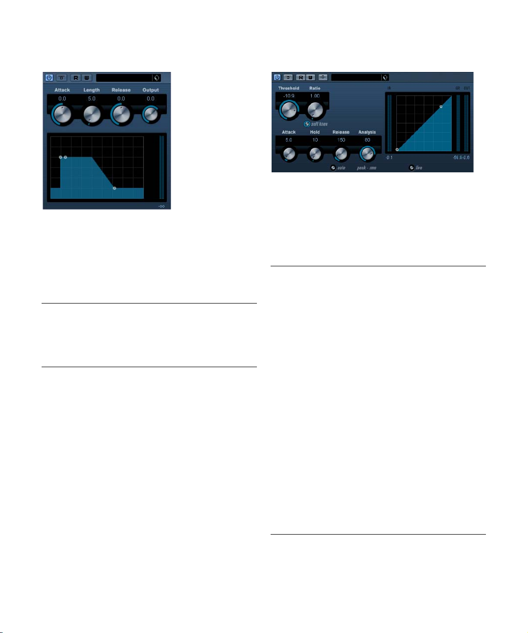
SPL DeEsser (Cubase only)
A de-esser is used to reduce excessive sibilance, primarily
for vocal recordings. Basically, it is a special type of compressor that is tuned to be sensitive to the frequencies
produced by the “s” sound, hence the name de-esser.
Close proximity microphone placement and equalizing can
lead to situations where the overall sound is just right, but
there is a problem with sibilants. Conventional compression and/or equalizing will not easily solve this problem,
but a de-esser can.
The SPL DeEsser has the following parameters:
Parameter Description
S-Reduction Controls the intensity of the de-essing effect. We recom-
Level display Indicates the dB value by which the level of the sibilant or
Auto Threshold See separate description below.
Male/Female This sets the s-frequency and sibilant recognition to the
mend that you start with a value between 4 and 7.
s-frequency is reduced. The display shows values between 0dB (no reduction) and minus 20dB (the s-frequency level is lowered by 20dB). Each segment in the
display represents a level reduction of 2 dB.
characteristic frequency ranges of the female or male
voice. The center frequency of the bandwidth at which the
SPL DeEsser operates is located in the 7 kHz range for the
female voice and in the 6kHz range for the male voice.
About the Auto Threshold function
Conventional de-essing devices all have a threshold parameter. This is used to set a threshold for the incoming
signal level, above which the device starts to process the
signal. The SPL DeEsser however has been designed for
utmost ease-of-use. With Auto Threshold on (the button
lights up) it automatically and constantly readjusts the
threshold to achieve an optimum result. If you still wish to
determine for yourself at which signal level the SPL
DeEsser should start to process the signal, deactivate the
Auto Threshold button. The SPL DeEsser will then use a
fixed threshold.
When recording a voice, usually the de-esser's position in
the signal chain is located after the microphone pre-amp
and before a compressor/limiter. This is useful, as it keeps
the compressor/limiter from unnecessarily limiting the
overall signal dynamics by reacting to excessive sibilants
and s-frequencies.
The Auto Threshold function keeps the processing on a
constant level. The input threshold value is automatically
and constantly adjusted to the audio input level. Even level
differences of say 20dB do not have a negative impact on
the result of the processing. The input levels may vary, but
processing remains constant.
11
The included effect plug-ins
Page 12
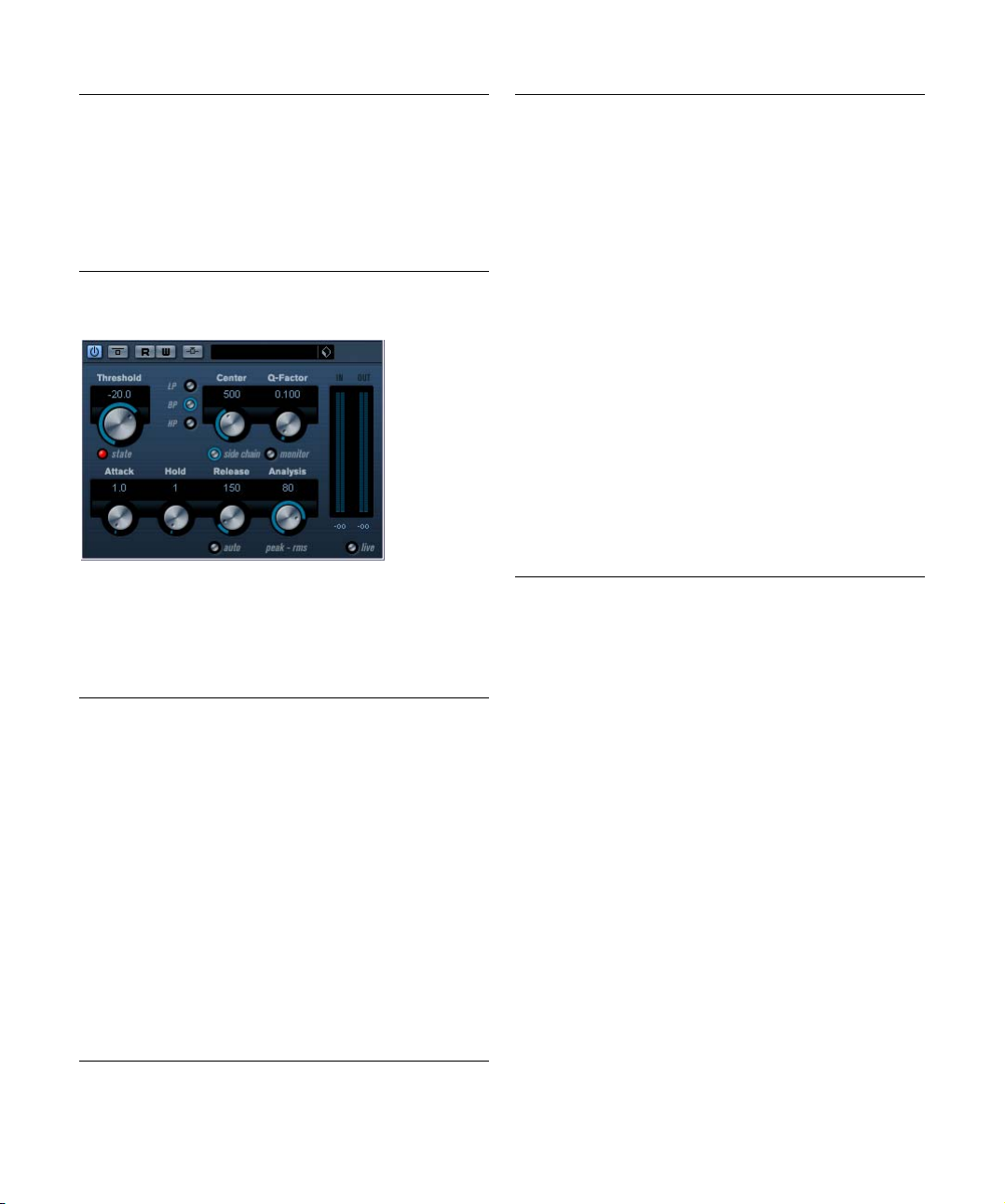
EnvelopeShaper (Cubase only)
EnvelopeShaper can be used to cut or boost the gain of
the Attack and Release phase of the audio material. You
can either use the knobs or drag the breakpoints in the
graphic display to change parameter values. Be careful
with levels when boosting the gain and if needed reduce
the Output level to avoid clipping.
The following parameters are available:
Parameter Description
Attack (-20–20dB) Changes the gain of the Attack phase of the signal.
Length (5–200ms) This determines the length of the Attack phase.
Release (-20–20dB) Changes the gain of the Release phase of the signal.
Output (-24–12dB) Sets the output level.
Expander (Cubase only)
Expander reduces the output level in relation to the input
level for signals below the set threshold. This is useful,
when you want to enhance the dynamic range or reduce
the noise in quiet passages. You can either use the knobs
or drag the breakpoints in the graphic display to change
the Threshold and the Ratio parameter values.
The following parameters are available:
Parameter Description
Threshold
(-60–0dB)
Ratio
(1:1–8:1)
Soft Knee
(On/Off)
Attack
(0.1–100ms)
Hold
(0–2000ms)
Release
(10–1000ms
or Auto mode)
Analysis
(0–100)
(Pure Peak to
Pure RMS)
This setting determines the level where expansion “kicks
in”. Signal levels below the set threshold are affected, but
signal levels above are not processed.
Ratio determines the amount of gain boost applied to signals below the set threshold.
If this is off, signals below the threshold will be expanded
instantly according to the set ratio ("hard knee"). When Soft
Knee is activated, the onset of expansion will be more gradual, producing a less drastic result.
This determines how fast Expander will respond to signals
below the set threshold. If the attack time is long, more of
the early part of the signal (attack) will pass through unprocessed.
Sets the time the applied expansion will affect the signal
below the Threshold.
Sets the amount of time it takes for the gain to return to its
original level when the signal exceeds the Threshold level. If
the “Auto” button is activated, Expander will automatically
find an optimal release setting that varies depending on the
audio material.
This parameter determines whether the input signal is analysed according to peak or RMS values (or a mixture of
both). A value of 0 is pure peak and 100 pure RMS. RMS
mode operates using the average power of the audio signal
as a basis, whereas Peak mode operates more on peak levels. As a general guideline, RMS mode works better on material with few transients such as vocals, and Peak mode
better for percussive material, with a lot of transient peaks.
12
The included effect plug-ins
Page 13
Parameter Description
Live mode
(On/Off)
Side-Chain
(On/Off)
When activated, Live mode disengages the look ahead feature of Expander. Look ahead does produce more accurate
processing but will add a certain amount of latency as a
trade-off. When Live mode is activated, there is no latency.
When this is activated, the expansion can be controlled by a
signal routed to the Side-Chain input. When the side-chain
signal exceeds the threshhold, the expansion is triggered.
For a description of how to set up Side-Chain routing, see
the chapter “Audio effects” in the Operation Manual.
Gate
Gating, or noise gating, silences audio signals below a
certain set threshold level. As soon as the signal level exceeds the set threshold, the gate opens to let the signal
through.
The available parameters are as follows:
Parameter Description
Threshold
(-60–0dB)
state LED This indicates whether the gate is open (LED lights up in
Filter buttons When the Side-chain button (see below) is activated, you
Side-chain
(Off/On)
Center
(50Hz–
20000Hz)
Q-Factor
(0.01–10000)
This setting determines the level where Gate is activated.
Signal levels above the set threshold trigger the gate to
open, and signal levels below the set threshold will close
the gate.
green), closed (LED lights up in red) or something in between (LED lights up in yellow).
can use these buttons to set the filter type to either Low
Pass, Band Pass or High Pass.
This button (below the Center knob) activates the filter. The
input signal can then be shaped according to set Center
and Q-Factor parameters which may be useful in tailoring
how the Gate operates.
Sets the center frequency of the filter.
Sets the Resonance of the filter.
Parameter Description
Monitor
(Off/On)
Attack
(0.1–1000
ms)
Hold
(0–2000ms)
Release
(10–1000ms
or “Auto”)
Analysis
(0–100)
(Pure Peak to
Pure RMS
Live mode
(On/Off)
Allows you to monitor the filtered signal.
This parameter sets the time it takes for the gate to open after being triggered. If the Live button (see below) is deactivated, it will ensure that the gate will already be open when a
signal above the threshold level is played back. Gate manages this by “looking ahead” in the audio material, checking
for signals loud enough to pass the gate.
This determines how long the gate stays open after the signal drops below the threshold level.
This parameter sets the amount of time it takes for the gate
to close (after the set hold time). If the “Auto” button is activated, Gate will find an optimal release setting, depending
on the audio program material.
This parameter determines whether the input signal is analysed according to Peak or RMS values (or a mixture of
both). A value of 0 is pure Peak and 100 pure RMS. RMS
mode operates using the average power of the audio signal
as a basis, whereas Peak mode operates more on peak levels. As a general guideline, RMS mode works better on material with few transients such as vocals, and Peak mode
better for percussive material, with a lot of transient peaks.
When activated, Live mode disengages the “look ahead”
feature of the Gate. Look ahead does produce more accurate processing but will add a certain amount of latency as
a trade-off. When Live mode is activated, there is no latency, which might be better for “live” processing.
13
The included effect plug-ins
Page 14
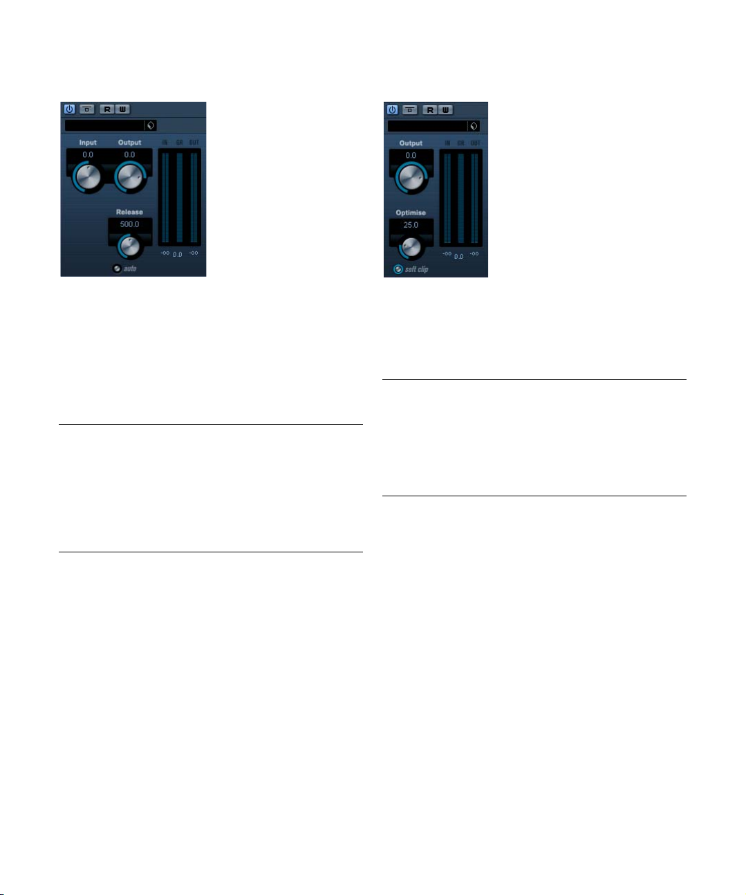
Limiter
Maximizer
Limiter is designed to ensure that the output level never
exceeds a certain set output level, to avoid clipping in following devices. Limiter can adjust and optimize the Release parameter automatically according to the audio
material, or it can be set manually. Limiter also features
separate meters for the input, output and the amount of
limiting (middle meters).
The available parameters are the following:
Parameter Description
Input
(-24–+24dB)
Output
(-24–+6dB)
Release
(0.1–1000ms
or
Auto mode)
Allows you to adjust the input gain.
This setting determines the maximum output level.
This parameter sets the amount of time it takes for the gain
to return to its original level. If the “Auto” button is activated,
Limiter will automatically find an optimal release setting that
varies depending on the audio material.
Maximizer can be used to raise the loudness of audio material without the risk of clipping. Optionally, there is a soft
clip function that removes short peaks in the input signal
and introduces a warm tubelike distortion to the signal.
The available parameters are the following:
Parameter Description
Output
(-24–+6dB)
Optimize
(0–100)
Soft Clip
(On/Off)
This setting determines the maximum output level. Should
normally be set to 0 (to avoid clipping).
This setting determines the loudness of the signal.
Soft Clipper starts limiting (or clipping) the signal “softly”,
at the same time generating harmonics which add a warm,
tubelike characteristic to the audio material.
14
The included effect plug-ins
Page 15
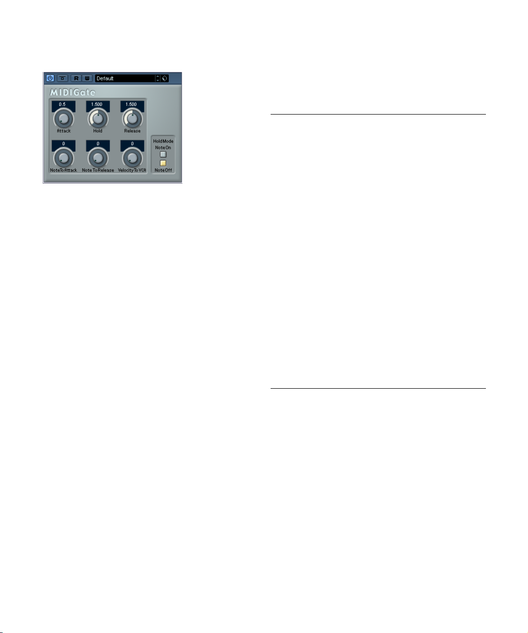
MIDI Gate
Gating, in its fundamental form, silences audio signals below a certain set threshold level. That means, when a signal rises above the set level, the Gate opens to let the
signal through while signals below the set level are cut off.
MIDI Gate, however, is a Gate effect that is not triggered
by threshold levels, but instead by MIDI notes. Hence it
needs both audio and MIDI data to function.
Setting up
MIDI Gate requires both an audio signal and a MIDI input
to function.
To set it up, proceed as follows:
1. Select the audio to be affected by the MIDI Gate.
This can be audio material from any audio track, or even a live audio input
(provided you have a low latency audio card).
2. Select the MIDI Gate as an insert effect for the audio
track.
The MIDI Gate control panel opens.
3. Select a MIDI track to control the MIDI Gate.
This can be an empty MIDI track, or a MIDI track containing data, it
doesn’t matter. However, if you wish to play the MIDI Gate in real-time –
as opposed to having a recorded part playing it – the track has to be
selected for the effect to receive the MIDI output.
4. Open the Output Routing pop-up menu for the MIDI
track and select the MIDI Gate option.
The MIDI Output from the track is now routed to the MIDI Gate.
What to do next depends on whether you are using live or
recorded audio and whether you are using real-time or recorded MIDI. We will assume for the purposes of this
manual that you are using recorded audio, and play the
MIDI in real-time.
Make sure the MIDI track is selected and start playback.
5. Now play a few notes on your MIDI keyboard.
As you can hear, the audio track material is affected by what you play on
your MIDI keyboard.
The following MIDI Gate parameters are available:
Parameter Description
Attack This is used for determining how long it should take for
Hold Regulates how long the Gate remains open after a Note
Release This determines how long it takes for the Gate to close
Note To
Attack
Note To
Release
Velocity To
VCA
Hold Mode Use this switch to set the Hold Mode. In Note-On mode,
the Gate to open after receiving a signal that triggers it.
On or Note Off message (see Hold Mode below).
(in addition to the value set with the Hold parameter).
The value you specify here determines to which extent
the velocity values of the MIDI notes should affect the Attack. The higher the value, the more the Attack time will
increase with high note velocities. Negative values will
give shorter Attack times with high velocities. If you do
not wish to use this parameter, set it to the 0 position.
The value you specify here determines to which extent
the velocity values of the MIDI notes should affect the Release. The higher the value, the more the Release time
will increase. If you do not wish to use this parameter, set
it to the 0 position.
This controls to which extent the velocity values of the
MIDI notes determine the output volume. A value of 127
means that the volume is controlled entirely by the velocity values, while a value of 0 means that velocities will
have no effect on the volume.
the Gate will only remain open for the time set with the
Hold and Release parameters, regardless of the length of
the MIDI note that triggered the Gate. In Note-Off mode
on the other hand, the Gate will remain open for as long
as the MIDI note plays, and then apply the Hold and Release parameters.
15
The included effect plug-ins
Page 16
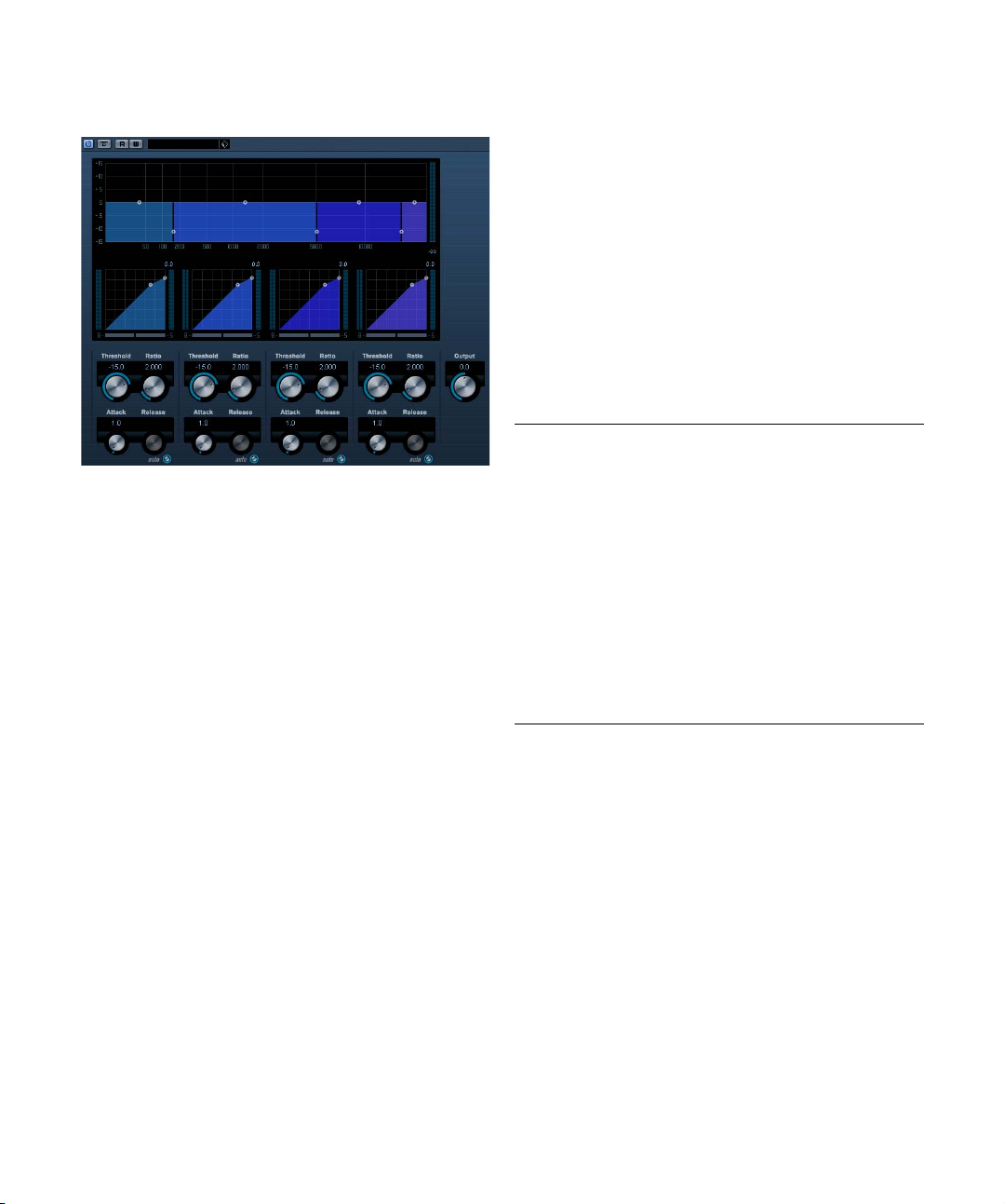
MultibandCompressor (Cubase only)
The MultibandCompressor allows a signal to be split in up
to four frequency bands, each with its own freely adjustable compressor characteristic. The signal is processed
on the basis of the settings that you have made in the Frequency Band and Compressor sections. You can specify
the level, bandwidth and compressor characteristics for
each band by using the various controls.
The Frequency Band editor
The Frequency Band editor in the upper half of the panel is
where you set the width of the frequency bands as well as
their level after compression. Two value scales and a number of handles are available. The vertical value scale to the
left shows the input gain level of each frequency band.
The horizontal scale shows the available frequency range.
The handles provided in the Frequency Band editor can
be dragged with the mouse. You use them to set the corner frequency range and the input gain levels for each frequency bands.
• The handles at the sides are used to define the frequency
range of the different frequency bands.
• By using the handles on top of each frequency band, you can
cut or boost the input gain by +/- 15dB after compression.
Bypassing frequency bands
Each frequency band can be bypassed using the “B” button in each compressor section.
Soloing frequency bands
A frequency band can be soloed using the “S” button in
each compressor section. Only one band can be soloed
at a time.
Using the Compressor section
By moving breakpoints or using the corresponding knobs,
you can specify the Threshold and Ratio. The first breakpoint from which the line deviates from the straight diagonal
will be the threshold point. The compressor parameters for
each of the four bands are as follows:
Parameter Description
Threshold
(-60–0dB)
Ratio
(1000–8000)
(1:1 to 8:1)
Attack
(0.1–
100ms)
Release
(10–
1000ms or
“Auto”)
This setting determines the level where Compressor “kicks
in”. Signal levels above the set threshold are affected, but
signal levels below are not processed.
Ratio determines the amount of gain reduction applied to
signals over the set threshold. A ratio of 3000 (3:1) means
that for every 3dB the input level increases, the output level
will increase by only 1dB.
This determines how fast the compressor will respond to
signals above the set threshold. If the attack time is long,
more of the early part of the signal (attack) will pass
through unprocessed.
Sets the amount of time it takes for the gain to return to its
original level when the signal drops below the Threshold
level. If the “Auto” button is activated, the compressor will
automatically find an optimal release setting that varies depending on the audio material.
The Output dial
The Output dial controls the total output level that the
MultibandCompressor passes on to Cubase. The range
available is +/- 24dB.
16
The included effect plug-ins
Page 17
VintageCompressor (Cubase only)
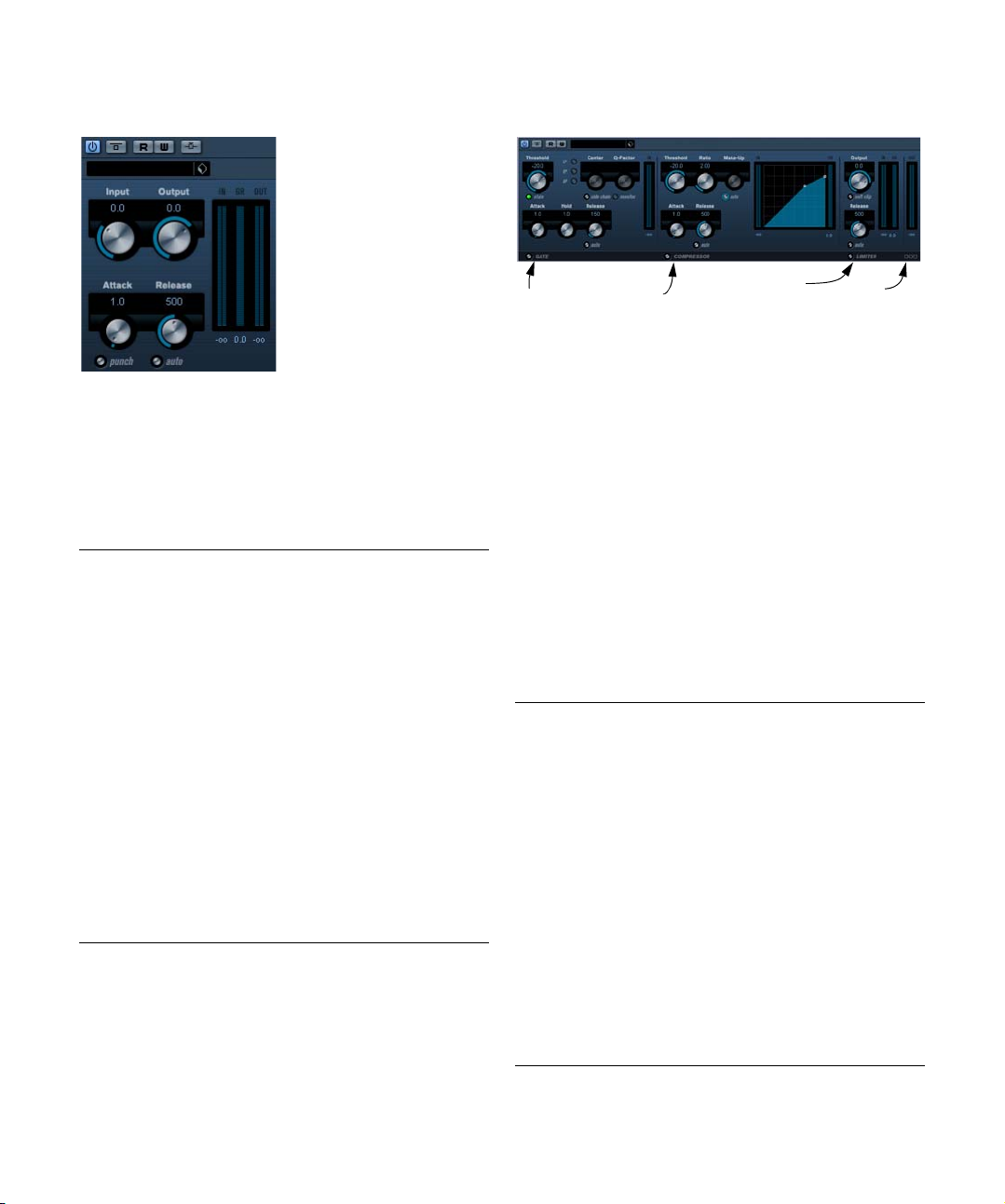
VSTDynamics
This is modelled after vintage type compressors. Compressor features separate controls for input gain, attack,
release and output gain parameters. In addition, there is a
Punch mode which preserves the attack phase of the signal and a program dependent Auto feature for the Release
parameter.
The available parameters work as follows:
Parameter Description
Input gain
(-24–48dB)
Output gain
(-48–24dB)
Attack
(0.1–100ms)
Punch
(Off/On)
Release
(10–1000ms
or “Auto
mode”)
Side-Chain
(On/Off)
This setting, together with the Output gain parameter determines the compression amount. The higher the Input
gain setting, and the lower the Output gain setting, the
more compression is applied.
Sets the output gain.
This determines how fast Compressor will respond. If the
attack time is long, more of the early part of the signal (attack) will pass through unprocessed.
When this is activated, the early attack phase of the signal
is preserved, retaining the original “punch” in the audio material, even with short Attack settings.
Sets the amount of time it takes for the gain to return to its
original level. If the “Auto” button is activated, Vintage
Compressor will automatically find an optimal release setting that varies depending on the audio material.
When this is activated, the compression can be controlled
by a signal routed to the Side-Chain input. When the sidechain signal exceeds the threshhold the compression is triggered. For a description of how to set up Side-Chain routing, see the chapter “Audio effects” in the Operation Manual.
Gate
Compressor
Limiter
Routing selector
VSTDynamics is an advanced dynamics processor. It combines three separate processors: Gate, Compressor and
Limiter, covering a variety of dynamic processing functions.
The window is divided into three sections, containing controls and meters for each processor.
Activating the individual processors
You activate the individual processors using the buttons
at the bottom of the plug-in panel.
The Gate section
Gating, or noise gating, is a method of dynamic processing
that silences audio signals below a certain set threshold
level. As soon as the signal level exceeds the set threshold,
the gate opens to let the signal through. The Gate trigger
input can also be filtered using an internal side-chain.
The available parameters are as follows:
Parameter Description
Threshold
(-60–0dB)
state This indicates whether the gate is open (LED lights up in
Side-chain
(On/Off)
LP (Lowpass),
BP (Bandpass),
HP (Highpass)
Center
(50–22000Hz)
Q-Factor
(0.001–10000)
This setting determines the level where Gate is activated.
Signal levels above the set threshold trigger the gate to
open, and signal levels below the set threshold will close
the gate.
green), closed (LED lights up in red) or something in between (LED lights up in yellow).
This button activates the internal side-chain filter. This
lets you filter out parts of the signal that might otherwise
trigger the gate in places you don’t want it to, or to boost
frequencies you wish to accentuate, allowing for more
control over the gate function.
These buttons set the basic filter mode.
This sets the center frequency of the filter.
This sets the resonance or width of the filter.
17
The included effect plug-ins
Page 18
Parameter Description
Monitor
(Off/On)
Attack
(0.1–100ms)
Hold
(0–2000ms)
Release
(10–1000ms or
“Auto”)
Allows you to monitor the filtered signal.
This parameter sets the time it takes for the gate to open
after being triggered.
This determines how long the gate stays open after the
signal drops below the threshold level.
This parameter sets the amount of time it takes for the
gate to close (after the set hold time). If the “Auto” button
is activated, Gate will find an optimal release setting, depending on the audio program material.
The Compressor section
Compressor reduces the dynamic range of the audio,
making softer sounds louder or louder sounds softer, or
both. Compressor functions like a standard compressor
with separate controls for threshold, ratio, attack, release
and make-up gain parameters. Compressor features a
separate display that graphically illustrates the compressor curve shaped according to the Threshold, Ratio and
MakeUp Gain parameter settings. Compressor also features a Gain Reduction meter that shows the amount of
gain reduction in dB, and a program dependent Auto feature for the Release parameter.
The available parameters work as follows:
Parameter Description
Threshold
(-60–0dB)
Ratio
(1:1–8:1)
Make-Up
(0–24dB)
Attack
(0.1–100ms)
Release
(10–1000ms
or “Auto”)
Graphic
display
This setting determines the level where Compressor “kicks
in”. Signal levels above the set threshold are affected, but
signal levels below are not processed.
Ratio determines the amount of gain reduction applied to
signals over the set threshold. A ratio of 3:1 means that for
every 3dB the input level increases, the output level will increase by only 1 dB.
This parameter is used to compensate for output gain loss,
caused by compression. When Auto is on, gain loss will be
compensated automatically.
This determines how fast Compressor will respond to signals above the set threshold. If the attack time is long, more
of the early part of the signal (attack) will pass through unprocessed.
Sets the amount of time it takes for the gain to return to its
original level when the signal drops below the Threshold
level. If the “Auto” button is activated, Compressor will automatically find an optimal release setting that varies depending on the audio material.
Use the graphic display to graphically set the Threshold or
the Ratio value.
The Limiter section
Limiter is designed to ensure that the output level never
exceeds a certain set output level, to avoid clipping in following devices. Conventional limiters usually require very
accurate setting up of the attack and release parameters,
to prevent the output level from going beyond the set
threshold level. Limiter adjusts and optimizes these parameters automatically, according to the audio material.
You can also adjust the Release parameter manually.
The available parameters are the following:
Parameter Description
Output
(-24–+6dB)
Soft Clip
(On/Off)
Release
(10–1000ms
or “Auto”)
This setting determines the maximum output level. Signal
levels above the set threshold are affected, but signal levels
below are left unaffected.
Soft Clipper acts differently compared to the limiter. When
the signal level exceeds -6dB, SoftClip starts limiting (or
clipping) the signal “softly”, at the same time generating
harmonics which add a warm, tubelike characteristic to the
audio material.
This parameter sets the amount of time it takes for the gain
to return to its original level when the signal drops below
the threshold level. If the “Auto” button is activated, Limiter
will automatically find an optimal release setting that varies
depending on the audio material.
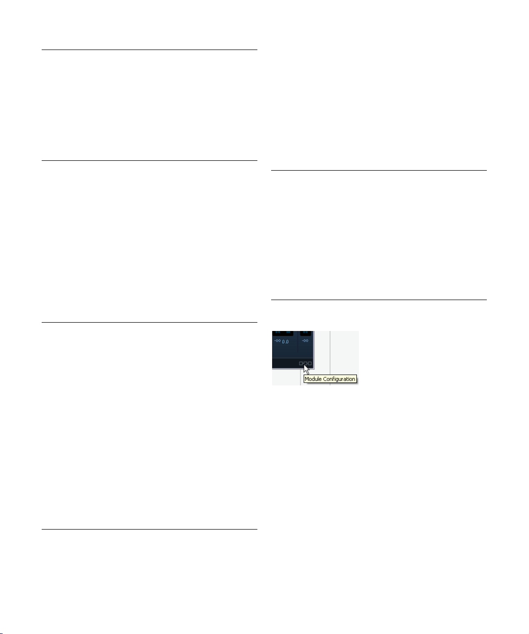
The Module Configuration button
In the bottom right corner of the plug-in panel you will find
a button with which you can set the signal flow order for
the three processors. Changing the order of the processors can produce different results, and the available options allow you to quickly compare what works best for a
given situation. Simply click the Module Configuration button to change to a different configuration. There are three
routing options:
• C-G-L (Compressor-Gate-Limit)
• G-C-L (Gate-Compressor-Limit)
• C-L-G (Compressor-Limit-Gate)
18
The included effect plug-ins
Page 19
EQ plug-ins
This section describes the plug-ins in the “EQ” category.
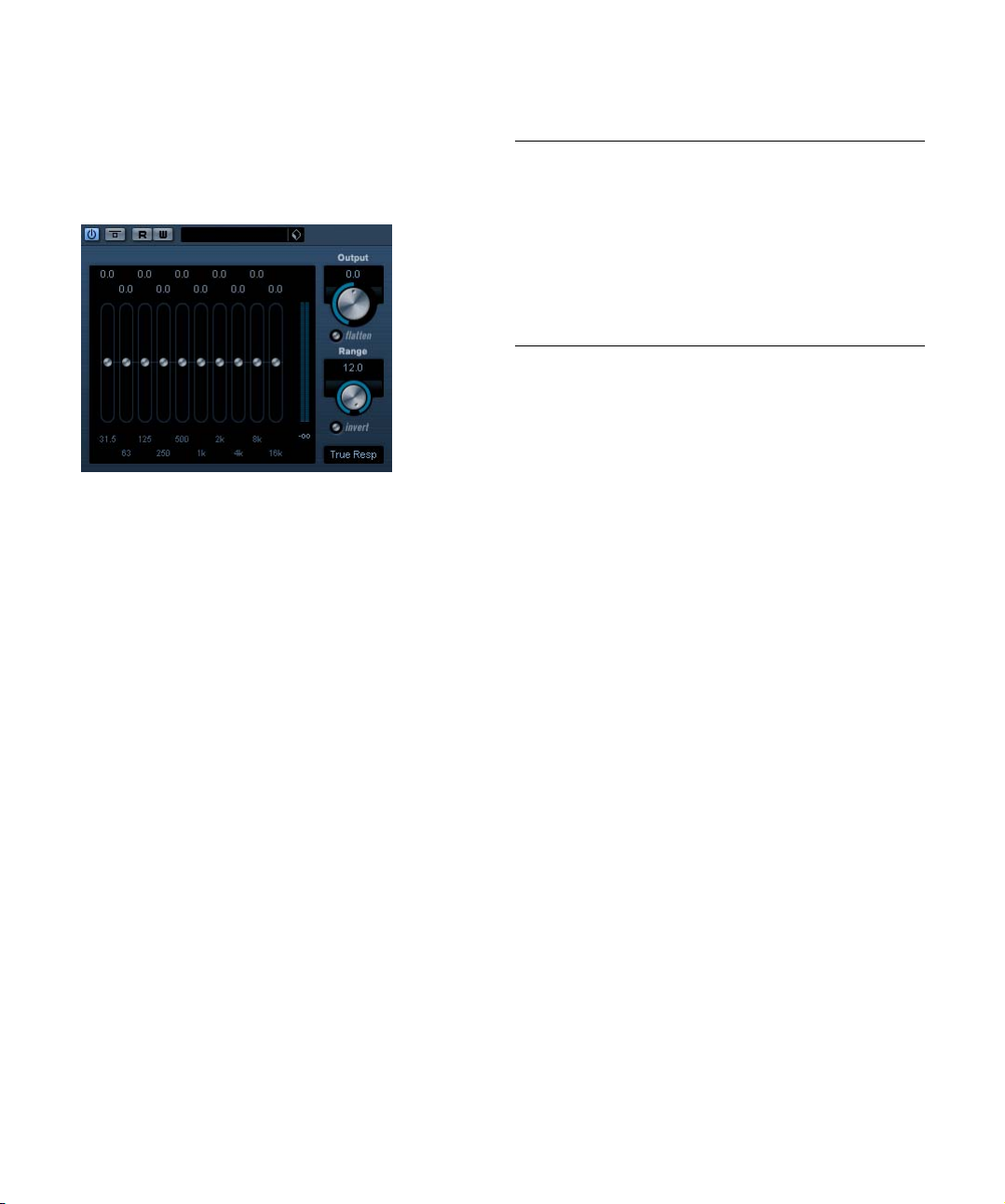
GEQ-10/GEQ-30 (Cubase only)
These graphic equalizers are identical in every respect except for the number of available frequency bands (10 and
30 respectively). Each band can be cut or boosted by up to
12dB allowing for fine control of the frequency response. In
addition there are several preset modes available which can
add “color” to the sound of the GEQ-10/GEQ-30.
• You can draw response curves in the main display by
click-dragging with the mouse.
Note that you have to click on one of the sliders first before dragging
across the display. You can also point and click to change individual frequency bands or enter values numerically by clicking on a gain value at
the top of the display.
• At the bottom of the window the respective frequency
bands are shown in Hz.
• At the top of the display, the amount of cut/boost is
shown in dB.
Apart from the frequency bands, the following parameters
are available:
Parameter Description
Output This controls the overall gain of the equalizer.
Range This allows you to relatively adjust how much a set curve
Flatten button Resets all the frequency bands to 0dB.
Invert range This will invert the current response curve.
Mode The filter mode set here determines how the various fre-
cuts or boosts the signal. If the Range parameter is
turned fully clockwise, +/- 12dB is the available range.
quency band contrrols interact to create the response
curve. See also below.
About the filter modes
On the pop-up in the lower right corner there are several
different EQ modes available. These modes can add color
or character to the equalized output in various ways, which
is sometimes desirable. As always, let your ears be the
judge! Here follow brief descriptions of the filter modes:
• True Response – serial filters with accurate frequency
response.
• Digi Standard – resonance of last band depends on sample
rate.
• Variable Q – parallell filters where the resonance depends on
the amount of gain. Musical sounding.
• Constant Q u – parallell filters where the resonance of the first
and last bands depends on the sample rate (u=unsymmetric).
• Constant Q s – parallell filters where the resonance is raised
when boosting the gain and vice versa (s=symmetric).
• Resonant – serial filters where a gain increase of one band will
lower the gain in adjacent bands.
19
The included effect plug-ins
Page 20
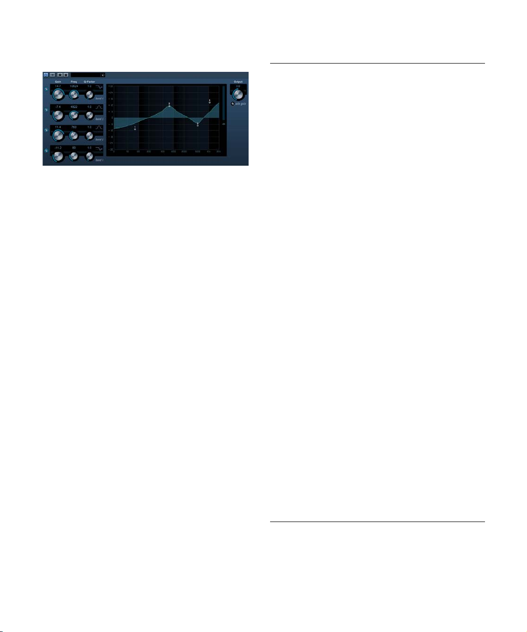
StudioEQ (Cubase only)
This is a high-quality 4-band parametric stereo equalizer
with two fully parametric midrange bands. The low and
high bands can act as either shelving filters (three types)
or as a Peak (bandpass) or Cut (lowpass/highpass) filter.
Making settings
1. Click the corresponding On button to the left of the EQ
curve display to activate any or all of the Low, Mid 1, Mid 2
or High equalizer bands.
When a band is activated, a corresponding eq point appears in the EQ
curve display.
2. Set the parameters for an activated EQ band.
This can be done in several ways:
• By using the knobs.
• By clicking a value field and entering values numerically.
• By using the mouse to drag points in the EQ curve display
window.
By using this method, you control both the Gain and Frequency parameters simultaneously. The knobs turn accordingly when you drag points.
The following parameters are available:
Parameter Description
Low Freq
(20 to 2000Hz)
Low Gain
(-20 to +24dB)
Low Q-Factor This controls the width or resonance of the Low band.
Low Filter
mode
Mid 1 Freq (20
to 20000Hz)
Mid 1 Gain
(+/- 24dB)
Mid 1 Q-Factor
(0.5 to 10)
Mid 2 Freq
(20 to
20000Hz)
Mid 2 Gain
(-20 to +24dB)
Mid 2 Q-Factor
(0.5 to 10)
High Freq
(200 to
20000Hz)
High Gain
(-20 to +24dB)
High Q-Factor This parameter controls the width or resonance of the
High Filter
mode
Output
(-24 to +24dB)
Auto Gain When this is activated, the gain is automatically adjusted,
This sets the frequency of the Low band.
This sets the amount of cut/boost for the Low band.
For the Low band, you can select between three types of
shelving filters or Peak (bandpass) or Cut (lowpass/highpass) filters. The Gain parameter will be fixed if Cut mode
is selected.
-Shelf I adds resonance in the opposite gain direction
slightly over the set frequency.
-Shelf II adds resonance in the gain direction at the set
frequency.
-Shelf III is a combination of Shelf I and II.
This sets the center frequency of the Mid 1 band.
This sets the amount of cut/boost for the Mid 1 band.
This sets the width of the Mid 1 band. The higher this
value, the “narrower” the bandwidth.
This sets the center frequency of the Mid 2 band.
This sets the amount of cut/boost for the Mid 2 band.
This sets the width of the Mid 2 band. The higher this
value, the “narrower” the bandwidth.
This sets the frequency of the High band.
This sets the amount of cut/boost for the High band.
High band.
For the High band, you can select between three types of
shelving filters, and Peak or Cut filters. The Gain parameter will be fixed if Cut mode is selected.
-Shelf I adds resonance in the opposite gain direction
slightly below the set frequency.
-Shelf II adds resonance in the gain direction at the set
frequency.
-Shelf III is a combination of Shelf I and II.
This parameter allows you to adjust the overall output
level.
keeping the output level constant regardless of the EQ
settings.
20
The included effect plug-ins
Page 21
Filter plug-ins
This section contains descriptions of the plug-ins in the
“Filter” category.
General operation
StepFilter can produce two simultaneous 16-step patterns
for the filter cutoff and resonance parameters, synchronized
to the sequencer tempo.
DualFilter
This effect filters out certain frequencies while allowing
others to pass through.
The following parameters are available:
Parameter Description
Position This parameter sets the filter cutoff frequency. If you set
Resonance Sets the sound characteristic of the filter. With higher
this to a negative value, DualFilter will act as a low-pass
filter. Positive values cause DualFilter to act as a highpass filter.
values, a ringing sound is heard.
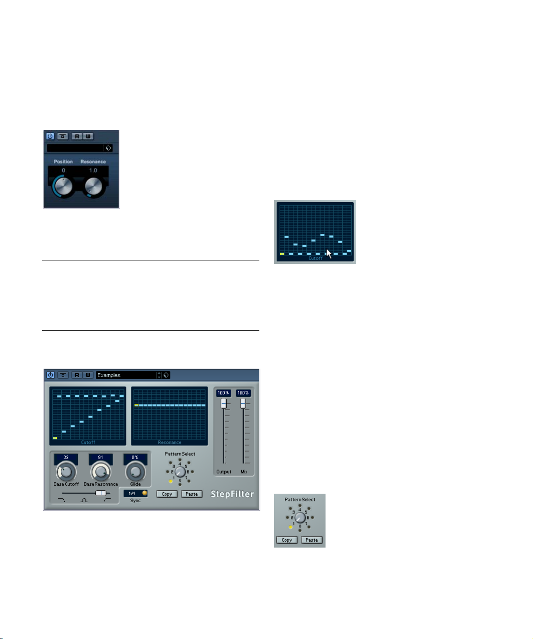
StepFilter
Setting step values
• Setting step values is done by clicking in the pattern
grid windows.
• Individual step entries can be freely dragged up or down
the vertical axis, or directly set by clicking in an empty grid
box. By click-dragging left or right, consecutive step entries
will be set to the pointer position.
Setting filter cutoff values in the grid window.
• The horizontal axis shows the pattern steps 1–16 from
left to right, and the vertical axis determines the (relative)
filter cutoff frequency and resonance setting.
The higher up on the vertical axis a step value is entered, the higher the
relative filter cutoff frequency or filter resonance setting.
• By starting playback and editing the patterns for the cutoff and resonance parameters, you can hear how your filter
patterns affect the sound source connected to StepFilter
directly.
Selecting new patterns
• Created patterns are saved with the project, and up to 8
different cutoff and resonance patterns can be saved internally.
Both the cutoff and resonance patterns are saved together in the 8 Pattern
memories.
• To select new patterns you use the pattern selector.
New patterns are all set to the same step value by default.
StepFilter is a pattern-controlled multimode filter that can
create rhythmic, pulsating filter effects.
The included effect plug-ins
Pattern Selector
21
Page 22
Using pattern copy and paste to create variations
You can use the Copy and Paste buttons below the pattern
selector to copy a pattern to another pattern memory location, which is useful for creating variations on a pattern.
• Select the pattern you wish to copy, click the Copy but-
ton, select another pattern memory location and click Paste.
The pattern is copied to the new location, and can now be edited to create variations using the original pattern as a starting point.
ToneBooster
StepFilter parameters
Parameter/
Value
Base Cutoff This sets the base filter cutoff frequency. Cutoff values
Base
Resonance
Glide This will apply glide between the pattern step values,
Filter Mode This slider selects between lowpass (LP), bandpass (BP)
Sync 1/1 to
1/32 (Straight,
Triplet or Dotted)
Output Sets the overall volume.
Mix Adjusts the mix between dry and processed signal.
Description
set in the Cutoff grid window are values relative to the
Base Cutoff value.
This sets the base filter resonance. Resonance values set
in the Resonance grid window are values relative to the
Base Resonance value. Note that very high Base Resonance settings can produce loud ringing effects at certain frequencies.
causing values to change more smoothly.
or highpass (HP) filter modes (from left to right respectively).
This sets the pattern beat resolution, i.e. what note values
the pattern will play in relation to the tempo.
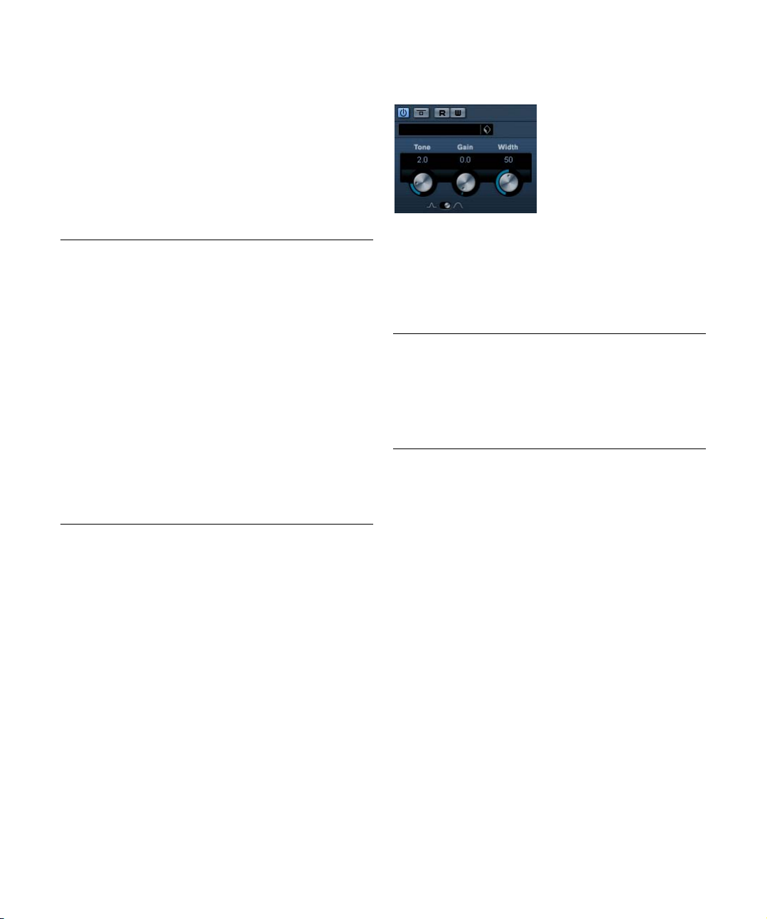
ToneBooster is a filter that allows you to raise the gain in a
selected frequency range. It is particularly useful when inserted before AmpSimulator in the plug-in chain (see
“AmpSimulator” on page 9), greatly enhancing the tonal
varieties available.
The following parameters are available:
Parameter Description
Tone This sets the center filter frequency.
Gain Allows you to adjust the gain of the selected frequency
Width This sets the resonance of the filter.
Mode This sets the basic operational mode of the filter; Peak or
range by up to 24dB.
Bandpass.
22
The included effect plug-ins
Page 23
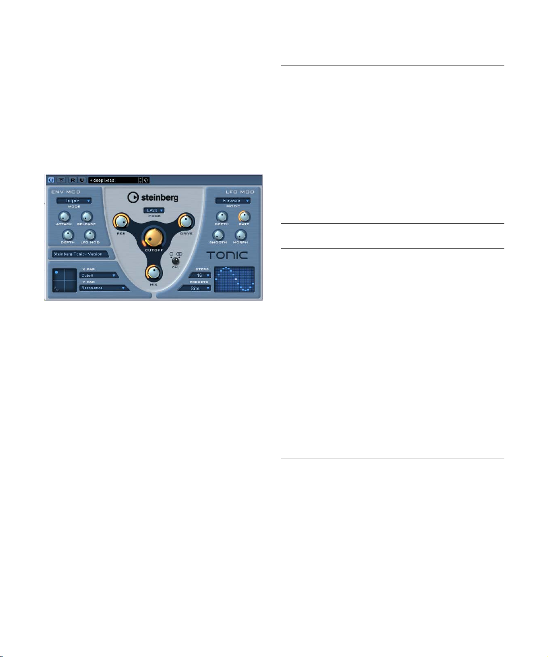
Tonic – Analog Modeling Filter
(Cubase only)
Tonic is a versatile and powerful analog modeling filter
plug-in based on the filter design of the Monologue monophonic synthesizer. Its variable characteristics plus the
powerful modulation functions make it an excellent choice
for all current music styles. Designed to be more a creative
tool rather than a tool to fix audio problems, it can add color
and punch to your tracks while being light on CPU usage.
The Tonic Analog Modeling Filter has the following properties:
• Dynamic multimode analog modeling filter (mono/stereo).
• 24dB low pass, 18dB low pass, 12 dB low pass, 6dB
low pass, 12dB band pass and 12dB high pass modes.
• Adjustable drive and resonance up to self-oscillation.
• Envelope follower for dynamic filter control with an
audio signal.
• Audio and MIDI trigger modes.
• Powerful step LFO with smoothing and morphing.
• X/Y matrix pad for additional realtime modulation with
access to all Tonic parameters.
Filter
Parameter Description
Mode Sets the filter type. Available filter types are: 24dB Low
Cutoff Sets the filter cutoff frequency. How this parameter oper-
Res Changes the resonance of the multi-mode filter. Full res-
Drive Drive adds a soft, tube-like saturation to the sound. Like
Mix Sets the balance between dry and effect signal.
Ch. Choose between mono or stereo operation. When set to
pass, 18dB Low pass, 12 dB Low pass, 6 dB Low pass,
12dB Band pass and 12 dB High pass.
ates is governed by the filter type.
onance puts the filter into self-oscillation.
for an analog filter, the amount of saturation also depends
on the input signal level.
mono, the output signal of Tonic will be mono regardless
of the input signal.
Env Mod
Parameter Description
Mode Tonic offers three types of envelope modulation:
Attack Controls the attack time of the envelope. Higher attack
Release Controls the release time of the envelope. Higher release
Depth Controls the amount of envelope control applied to the
LFO Mod Using this parameter, envelope level modulates the LFO
“Follow” tracks the input signal’s volume envelope for dynamic control of the filter cutoff.
“Trigger” uses the input signal to trigger the envelope
and have it run through a single envelope cycle.
“MIDI” uses any MIDI note to trigger the envelope. The filter cutoff tracks the keys played on the keyboard. In addition velocities higher than 80 will add an accent to the
envelope by increasing the envelope depth and reducing
the decay time.
For MIDI control, set up a separate MIDI control track and
select “Tonic” from the output pop-up menu for the track.
times result in slower rise times when the envelope is
triggered.
times result in slower envelope tails.
filter cutoff level.
speed. A rather stunning effect.
23
The included effect plug-ins
Page 24
X/Y Pad
Parameter Description
X Par Sets the parameter to be modulated on the x axis of the
Y Par Sets the parameter to be modulated on the y axis of the
XY Pad Use the mouse to control any two of Tonic’s parameters
XY Pad. All of Tonic’s parameters are available as destinations
XY Pad.
in combination. By moving the mouse horizontally, you
can control the x parameter, by moving it vertically, you
can control the y parameter. You can also record controller movements as automation data.
LFO Mod
Parameter Description
Mode Sets the direction of the step LFO modulation. The avail-
Depth Controls the amount of LFO modulation applied to the fil-
Rate Controls the speed of the LFO modulation. The LFO rate
Smooth The smooth parameter controls the smoothing of the LFO
Morph Morph controls the playback value of the LFO step se-
Steps Sets the number of steps played in sequence. Deacti-
Preset Offers a number of step LFO waveform patterns.
Step Matrix Click into the step matrix to set the level for each of the
able modes are: Forward, Reverse, Alternating, and Random.
ter cutoff level.
is always in sync with the song tempo. For example: a
rate of 4.00 steps per beat advances the step sequencer
in 16th notes at a 4/4 time signature. A rate of 4.00 beats
per step would advance the LFO at only one step per bar
in a 4/4 time signature.
steps. This works like a glide effect applied to the filter cutoff.
quencer. It makes the LFO steps drift about randomly.
Experiment freely with the morph parameter. As you return the knob to its zero position the step pattern will return to its original setting.
vated steps are grayed out in the step window.
Choices include: Sine, Sine+, Cosine, Triangle, Sawtooth, Square, Random and User (which is the pattern
saved with the respective program).
16 LFO steps. A higher amount results in a deeper filter
cutoff modulation. Click and drag along the matrix to
“draw” a waveform.
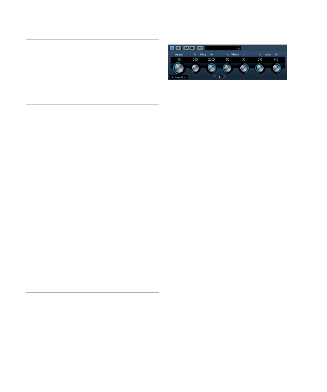
WahWah
WahWah is a variable slope bandpass filter that can be
auto-controlled by a side-chain signal or via MIDI modeling the well-known analog pedal effect (see below). You
can independently specify the frequency, width and the
gain for the Lo and Hi Pedal positions. The crossover
point between the Lo and Hi Pedal positions is at 50.
The parameters are as follows:
Parameter Description
Pedal This controls the filter frequency sweep.
Freq Lo/Hi Sets the frequency of the filter for the Lo and Hi Pedal
Width Lo/Hi Sets the width (resonance) of the filter for the Lo and Hi
Gain Lo/Hi Sets the gain of the filter for the Lo and Hi Pedal posi-
Slope Specifies the slope of the filter; 6dB or 12dB.
Side-Chain
On/Off
MIDI control
For real-time MIDI control of the Pedal parameter, MIDI
must be directed to the WahWah plug-in.
• Whenever the WahWah has been added as an insert
effect (for an audio track or an FX channel), it will be available on the Output Routing pop-up menu for MIDI tracks.
If WahWah is selected on the Output Routing menu, MIDI will be directed to the plug-in from the selected track.
positions.
Pedal positions.
tions.
A signal routed to the Side-Chain input of the effect can
control the Pedal parameter when this is activated. The
louder the signal, the more the filter frequency (Pedal) is
raised so the plug-in acts as an “auto-wha” effect. For a
description of how to set up Side-Chain routing, see the
chapter “Audio effects” in the Operation Manual.
24
The included effect plug-ins
Page 25
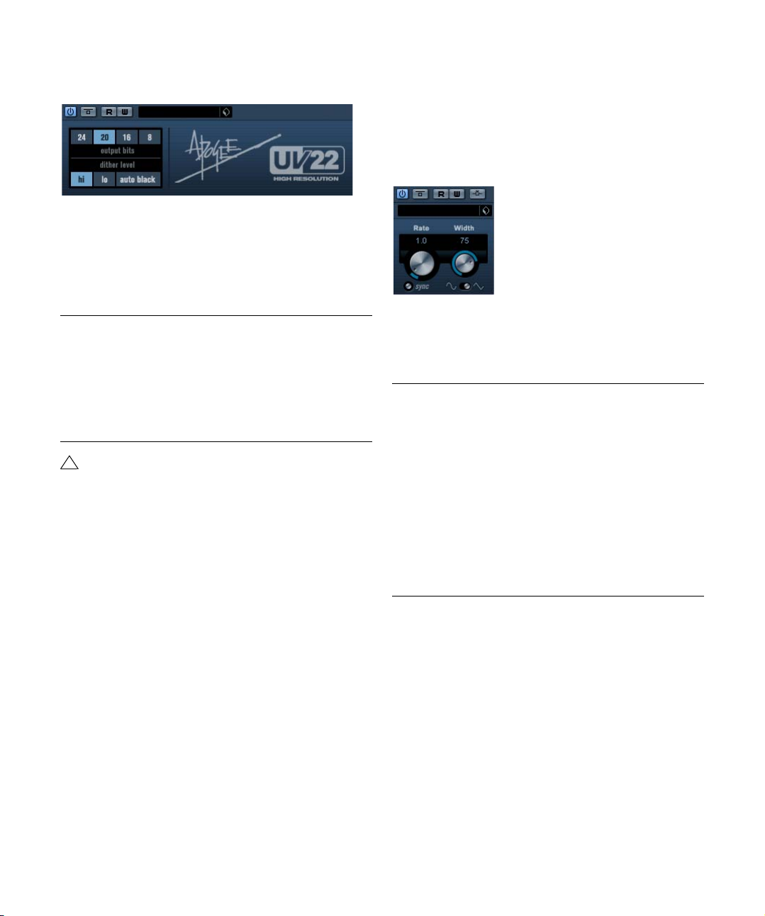
Mastering – UV 22 HR (Cubase only)
The UV22 HR is a dithering plug-in, based on an advanced
algorithm developed by Apogee. For an introduction to the
concept of dithering, see the chapter “Audio Effects” in the
Operation Manunal.
The following options can be set in the UV 22 HR control
panel:
Option Description
Hi Try this first, it is the most “all-round” setting.
Low This applies a lower level of dither noise.
Auto black When this is activated, the dither noise is gated (muted)
Bit Resolution The UV22 HR supports dithering to multiple resolutions:
!
Dither should always be applied post output bus
fader.
during silent passages in the material.
8, 16, 20 or 24 bits. You select the desired resolution by
clicking the corresponding button.
Modulation plug-ins
This section contains descriptions of the plug-ins in the
“Modulation” category.
AutoPan
This is a simple autopan effect. It can use different waveforms to modulate the left-right stereo position (pan), either
using tempo sync or manual modulation speed settings.
The parameters are as follows:
Parameter Description
Rate If tempo sync is on, this is where you specify the base
Tempo sync
on/off
Width Sets the depth of the Autpan effect.
Shape Sets the modulation waveform. Sine and Triangle wave-
Side-Chain
On/Off
note value for tempo-syncing the effect (1/1 to 1/32,
straight, triplet or dotted).
If tempo sync is off, the auto-pan speed can be set freely
with the Rate knob, without sync to tempo.
The button below the Rate knob is used to switch tempo
sync on (the button lights up) or off.
forms are available.
A signal routed to the Side-Chain input of the effect can
control the Width parameter when this is activated. For a
description of how to set up Side-Chain routing, see the
chapter “Audio effects” in the Operation Manual.
25
The included effect plug-ins
Page 26
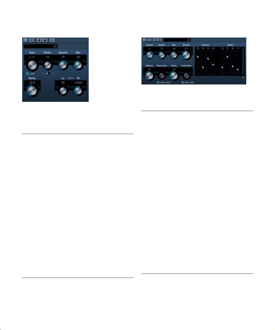
Chorus
This is a single stage chorus effect. It works by doubling
whatever is sent into it with a slightly detuned version. See
also “StudioChorus” on page 30.
The parameters are as follows:
Parameter Description
Tempo sync
on/off
Rate If tempo sync is on, this is where you specify the base
Width This determines the depth of the chorus effect. Higher
Spatial This sets the stereo width of the effect. Turn clockwise
Mix Sets the level balance between the dry signal and the ef-
Delay This parameter affects the frequency range of the modu-
Shape This changes the shape of the modulating waveform, al-
Filter Lo/Hi These parameters allow you to roll off low and high fre-
Side-Chain
On/Off
The button below the Rate knob is used to switch tempo
sync on or off. The button is lit when tempo sync is on.
note value for tempo syncing the chorus sweep (1/1 to
1/32, straight, triplet or dotted).
If tempo sync is off, the sweep rate can be set freely with
the Rate knob, without sync to tempo.
settings produce a more pronounced effect.
for a wider stereo effect.
fect. If StudioChorus is used as a send effect, this should
be set to maximum as you can control the dry/effect balance with the send.
lation sweep, by adjusting the initial delay time.
tering the character of the chorus sweep. Sine and triangle waveforms are available.
quencies of the effect signal, respectively.
When this is activated, the modulation can be controlled
by a signal routed to the Side-Chain input. When the
side-chain signal exceeds the threshhold the modulation
will be controlled by the side-chain signal’s envelope. For
a description of how to set up Side-Chain routing, see
the chapter “Audio effects” in the Operation Manual.
Cloner (Cubase only)
The Cloner plug-in adds up to four detuned and delayed
voices to the signal, for rich modulation and chorus effects.
The parameters are as follows:
Parameter Description
Voices This allows you to select the number of voices (up to
Spatial This spreads the added voices across the stereo spec-
Mix Sets the level balance between the dry signal and the ef-
Output Allows you to reduce or increase the output gain by up to
Detune slider
1–4
Delay slider
1–4
Master Detune This parameter governs the overall depth of the detuning
Humanize Delay
knob
Humanize Detune knob
Master Delay This parameter governs the overall depth of the delay for
four). For each added voice, a Detune and a Delay slider
are added in the right half of the panel.
trum. Turn clockwise for a deeper stereo effect.
fect. If Cloner is used as a send effect, this should be set
to maximum as you can control the dry/effect balance
with the send.
+/- 12dB.
This controls the relative detune amount for each voice.
Positive and negative values can be set, from -100 to
100. A value of zero means no detune for that voice.
This controls the relative delay amount for each voice. A
value of zero means no delay for that voice.
for all voices. If this is set to zero, no detuning takes
place, regardless of the Detune slider settings.
Humanize is turned on and off with the Static Delay button
button below this knob. When activated the delay settings
are subtly varied, for a richer effect. Values range from 0 to
100 (strongest delay variation). If deactivated, the set delay amount is static, and the knob is blacked out.
Humanize is turned on and off with the Static Detune button below this knob. When activated, the detune settings
are subtly varied, for a richer effect. Values range from 0
to 100 (strongest detune variation). If deactivated, the set
detune amount is static, and the knob is blacked out.
all voices. If this is set to zero, no delay takes place, regardless of the Delay slider settings.
26
The included effect plug-ins
Page 27
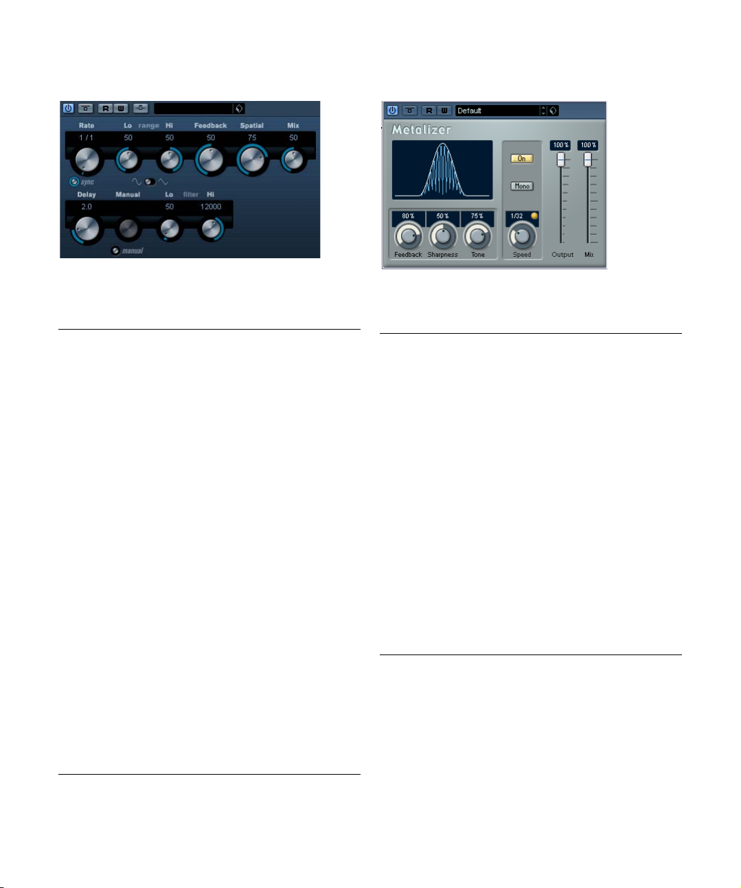
Flanger
Metalizer
Flanger is a classic flanger effect with added stereo
enhancement.
The parameters are as follows:
Parameter Description
Tempo sync on/
off
Rate If tempo sync is on, this is where you specify the base
Range Lo/Hi This sets the frequency boundaries for the flanger sweep.
Feedback This determines the character of the flanger effect.
Spatial This sets the stereo width of the effect. Turn clockwise
Mix Sets the level balance between the dry signal and the ef-
Shape This changes the shape of the modulating waveform, al-
Delay This parameter affects the frequency range of the modu-
Manual If this is activated, the flanger sweep will be static, i.e. no
Filter Lo/Hi These parameters allow you to roll off low and high fre-
Side-Chain
On/Off
The button below the Rate knob is used to switch tempo
sync on or off. The button is lit when tempo sync is on.
note value for tempo syncing the flanger sweep (1/1 to
1/32, straight, triplet or dotted).
If tempo sync is off, the sweep rate can be set freely with
the Rate knob, without sync to tempo.
Higher settings produce a more “metallic” sounding
sweep.
for a wider stereo effect.
fect. If the Flanger is used as a send effect, this should be
set to maximum as you can control the dry/effect balance
with the send.
tering the character of the flanger sweep.
lation sweep, by adjusting the initial delay time.
modulation. You can instead change the sweep position
manually by turning this knob.
quencies of the effect signal, respectively.
When this is activated, the modulation can be controlled
by a signal routed to the Side-Chain input. When the
side-chain signal exceeds the threshhold the modulation
will be controlled by the side-chain signal’s envelope. For
a description of how to set up Side-Chain routing, see
the chapter “Audio effects” in the Operation Manual.
The Metalizer feeds the audio signal through a variable
frequency filter, with tempo sync or time modulation and
feedback control.
Parameter Description
Feedback The higher the value, the more “metallic” the sound.
Sharpness Governs the character of the filter effect. The higher the
Tone Governs the feedback frequency. The effect of this will
On button Turns filter modulation on and off. When turned off, the
Mono button When this is on, the output of the Metalizer will be in mono.
Speed If tempo sync is on, this is where you specify the base
Tempo sync
on/off
Output Sets the overall volume.
Mix Sets the level balance between the dry signal and the ef-
value, the narrower the affected frequency area, producing sharper sound and a more pronounced effect.
be more noticeable with high Feedback settings.
Metalizer will work as a static filter.
note value for tempo-syncing the effect (1/1 to 1/32,
straight, triplet or dotted). Note that there is no note value
modifier for this effect.
If tempo sync is off, the modulation speed can be set
freely with the Speed knob, without sync to tempo.
The button above the Speed knob is used to switch tempo
sync on or off. The button is lit when tempo sync is on.
fect. If Metalizer is used as a send effect, this should be
set to maximum as you can control the dry/effect balance
with the send.
27
The included effect plug-ins
Page 28
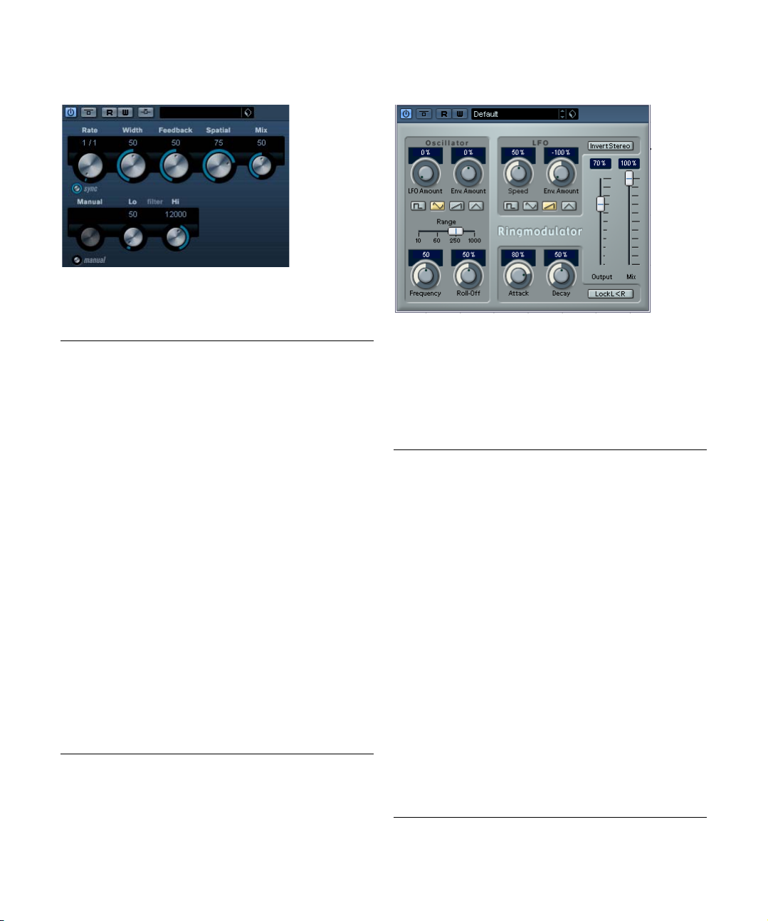
Phaser
Phaser produces the well-known “swooshing” phasing
effect with additional stereo enhancement.
The parameters are as follows:
Parameter Description
Tempo sync
on/off
Rate If tempo sync is on, this is where you specify the base
Width The width of the modulation effect between higher and
Feedback This determines the character of the phaser effect.
Spatial When using multi-channel audio, Spatial creates a 3-di-
Mix Sets the level balance between the dry signal and the ef-
Manual If this is activated, the phaser sweep will be static, i.e. no
Filter Lo/Hi These parameters allow you to roll off low and high fre-
Side-Chain
On/Off
The button below the Rate knob is used to switch tempo
sync on or off. The button is lit when tempo sync is on.
note value for tempo syncing the phaser sweep (1/1 to
1/32, straight, triplet or dotted).
If tempo sync is off, the sweep rate can be set freely with
the Rate knob, without sync to tempo.
lower frequencies.
Higher settings produce a more pronounced effect.
mensional impression by delaying modulation in each
channel.
fect. If the Phaser is used as a send effect, this should be
set to maximum as you can control the dry/effect balance
with the send.
modulation. You can instead change the sweep position
manually by turning this knob.
quencies of the effect signal, respectively.
When this is activated, the modulation can be controlled
by a signal routed to the Side-Chain input. When the
side-chain signal exceeds the threshhold the modulation
will be controlled by the side-chain signal’s envelope. For
a description of how to set up Side-Chain routing, see
the chapter “Audio effects” in the Operation Manual.
Ringmodulator
The Ringmodulator can produce complex, bell-like enharmonic sounds. Ring modulators work by multiplying two
audio signals. The ring modulated output contains added
frequencies generated by the sum of, and the difference
between, the frequencies of the two signals.
The Ringmodulator has a built-in oscillator that is multiplied with the input signal to produce the effect.
Parameter Description
Oscillator LFO
Amount
Oscillator Env.
Amount
Oscillator Wave Selects the oscillator waveform; square, sine, saw or
Oscillator Range Determines the frequency range of the oscillator in Hz.
Oscillator
Frequency
Oscillator
Roll-Off
LFO Speed Sets the LFO Speed.
LFO Env.
Amount
LFO Waveform Selects the LFO waveform; square, sine, saw or triangle.
Controls how much the oscillator frequency is affected
by the LFO.
Controls how much the oscillator frequency is affected
by the envelope (which is triggered by the input signal).
Positive and negative values can be set, with center position representing no modulation. Left of center, a loud input signal will decrease the oscillator pitch, whereas right
of center the oscillator pitch will increase when fed a loud
input.
triangle.
Sets the oscillator frequency +/- 2 octaves within the selected range.
Cuts high frequencies in the oscillator waveform, to
soften the overall sound. This is best used when harmonically rich waveforms are selected (e.g. square or saw).
Controls how much the input signal level – via the envelope generator – affects the LFO speed. Positive and
negative values can be set, with center position representing no modulation. Left of center, a loud input signal
will slow down the LFO, whereas right of center a loud input signal will speed it up.
28
The included effect plug-ins
Page 29

Parameter Description
Invert Stereo This inverts the LFO waveform for the right channel of the
Envelope
Generator
(Attack and
Decay dials)
Lock L<R When this button is enabled, the L and R input signals
Output Sets the overall volume.
Mix Adjusts the mix between dry and processed signal.
oscillator, which produces a wider stereo perspective for
the modulation.
The Envelope Generator section controls how the input
signal is converted to envelope data, which can then be
used to control oscillator pitch and LFO speed. It has two
main controls:
Attack sets how fast the envelope output level rises in response to a rising input signal.
Decay controls how fast the envelope output level falls in
response to a falling input signal.
are merged, and produce the same envelope output level
for both oscillator channels. When disabled, each channel has its own envelope, which affects the two channels
of the oscillator independently.
Rotary
The Rotary plug-in simulates the classic effect of a rotary
speaker. A rotary speaker cabinet features variable speed
rotating speakers to produce a swirling chorus effect, commonly used with organs. Rotary features all the parameters
associated with the real thing.
The parameters are as follows:
Parameter Description
Speed
(Stop/Slow/
Fast)
Mode Selects whether the Slow/Fast setting is a switch or a
Speed Mod Selects the Rotary speed from 0 (Stop) to 100 (Fast).
Overdrive Applies a soft overdrive or distortion.
Crossover Freq. Sets the crossover frequency (200–3000Hz) between
Slow Fine adjustment of the high rotor Slow speed.
Accel. Fine adjustment of the high rotor acceleration time.
This controls the speed of the Rotary in three steps.
variable control. When switch mode is selected and Pitch
Bend is the controller, the speed will switch with an up or
down flick of the bender. Other controllers switch at 64.
the low and high frequency loudspeakers.
Parameter Description
Fast Fine adjustment of the high rotor Fast speed.
Amp Mod High rotor amplitude modulation.
Freq Mod High rotor frequency modulation.
Slow Fine adjustment of the low rotor Slow speed.
Fast Fine adjustment of the low rotor Fast speed.
Accel Fine adjustment of the low rotor acceleration time.
Amp Mod. Adjusts amplitude modulation depth.
Level Adjusts overall bass level.
Phase Adjusts the phasing amount in the sound of the high rotor.
Angle Sets the simulated microphone angle. 0 = mono, 180 =
Distance Sets the simulated microphone distance from the
Output Adjusts the overall output level.
Mix Adjusts the mix between dry and processed signals.
one mic on each side.
speaker in inches.
Directing MIDI to the Rotary
For real-time MIDI control of the Speed parameter, MIDI
must be directed to the Rotary.
• Whenever the Rotary has been added as an insert effect (for an audio track or an FX channel), it will be available on the Output Routing pop-up menu for MIDI tracks.
If Rotary is selected on the “out:” menu, MIDI will be directed to the plugin from the selected track.
29
The included effect plug-ins
Page 30

StudioChorus
The StudioChorus plug-in is a two stage chorus effect
which adds short delays to the signal and pitch modulates
the delayed signals to produce a “doubling” effect. The
two separate stages of chorus modulation are completely
independent and are processed serially (cascaded).
The parameters for each stage are as follows:
Parameter Description
Tempo sync
on/off
Rate If tempo sync is on, this is where you specify the base
Width This determines the depth of the chorus effect. Higher
Spatial This sets the stereo width of the effect. Turn clockwise
Mix Sets the level balance between the dry signal and the ef-
Delay This parameter affects the frequency range of the modu-
Shape This changes the shape of the modulating waveform, al-
Filter Lo/Hi These parameters allow you to roll off low and high fre-
Side-Chain
On/Off
The button below the Rate knob is used to switch tempo
sync on or off. The button is lit when tempo sync is on.
note value for tempo syncing the chorus sweep (1/1 to
1/32, straight, triplet or dotted).
If tempo sync is off, the sweep rate can be set freely with
the Rate knob, without sync to tempo.
settings produce a more pronounced effect.
for a wider stereo effect.
fect. If StudioChorus is used as a send effect, this should
be set to maximum as you can control the dry/effect balance with the send.
lation sweep, by adjusting the initial delay time.
tering the character of the chorus sweep. Sine and triangle waveforms are available.
quencies of the effect signal, respectively.
When this is activated, the modulation can be controlled
by a signal routed to the Side-Chain input. When the
side-chain signal exceeds the threshhold, the modulation
will be controlled by the side-chain signal’s envelope. For
a description of how to set up Side-Chain routing, see
the chapter “Audio effects” in the Operation Manual.
Tranceformer
Tranceformer is a ring modulator effect, in which the incoming audio is ring modulated by an internal, variable frequency oscillator, producing new harmonics. A second
oscillator can be used to modulate the frequency of the
first oscillator, in sync with the Song tempo if needed.
Parameter Description
Waveform
buttons
Tone Sets the frequency (pitch) of the modulating oscillator
Depth Governs the depth of the pitch modulation.
Speed If tempo sync is on, this is where you specify the base
Tempo sync
on/off
On button Turns modulation of the pitch parameter on or off.
Mono button Governs whether the output will be stereo or mono.
Output Adjusts the output level of the effect.
Mix Sets the level balance between the dry signal and the
Ö Note that clicking and dragging in the display allows
you to adjust the Tone and Depth parameters at the same
time!
Sets the pitch modulation waveform.
(1 to 5000Hz).
note value for tempo-syncing the effect (1/1 to 1/32,
straight, triplet or dotted). Note that there is no note value
modifier for this effect. If tempo sync is off, the modulation speed can be set freely with the Speed knob, without
sync to tempo.
The button above the Speed knob is used to switch tempo
sync on or off. The button is lit when tempo sync is on.
effect.
30
The included effect plug-ins
Page 31

Tremolo
Vibrato
Tremolo produces amplitude (volume) modulation.
Parameters are as follows:
Parameter Description
Tempo sync
on/off
Rate If tempo sync is on, this is where you specify the base
Depth This governs the depth of the amplitude modulation.
Spatial This will add a stereo effect to the modulation.
Output Adjusts the output volume.
Side-Chain
On/Off
The button below the Rate knob is used to switch tempo
sync on or off. The button is lit when tempo sync is on.
note value for tempo-syncing the effect (1/1 to 1/32,
straight, triplet or dotted).
If tempo sync is off, the modulation speed can be set
freely with the Rate knob, without sync to tempo.
When this is activated, the modulation can be controlled
by a signal routed to the Side-Chain input. When the
side-chain signal exceeds the threshhold, the modulation
will be controlled by the side-chain signal’s envelope. For
a description of how to set up Side-Chain routing, see
the chapter “Audio effects” in the Operation Manual.
The Vibrato plug-in produces pitch modulation.
Parameter Description
Tempo sync
on/off
Rate If tempo sync is on, this is where you specify the base
Depth This governs the depth of the pitch modulation.
Spatial This will add a stereo effect to the modulation.
Side-Chain
On/Off
The button below the Rate knob is used to switch tempo
sync on or off. The button is lit when tempo sync is on.
note value for tempo-syncing the effect (1/1 to 1/32,
straight, triplet or dotted).
If tempo sync is off, the modulation speed can be set
freely with the Rate knob, without sync to tempo.
When this is activated, the modulation can be controlled
by a signal routed to the Side-Chain input. When the
side-chain signal exceeds the threshhold, the modulation
will be controlled by the side-chain signal’s envelope. For
a description of how to set up Side-Chain routing, see
the chapter “Audio effects” in the Operation Manual.
31
The included effect plug-ins
Page 32

Other plug-ins
This section contains descriptions of the plug-ins in the
“Others” category.
Bitcrusher
If you’re into lo-fi sound, Bitcrusher is the effect for you. It
offers the possibility of decimating and truncating the input audio signal by bit reduction, to get a noisy, distorted
sound. You can for example make a 24-bit audio signal
sound like an 8 or 4-bit signal, or even render it completely
garbled and unrecognizable. The parameters are:
Parameter Description
Mode Select one of four operating modes for the Bitcrusher.
Sample Divider This sets the amount by which the audio samples are
Depth Use this to set the desired bit resolution. A setting of 24
Output Governs the output level from the Bitcrusher. Drag the
Mix This slider regulates the balance between the output from
Each mode will produce a result sounding a bit different.
Modes I and III are nastier and noisier, while modes II and
IV are more subtle.
decimated. At the highest setting (65), nearly all of the information describing the original audio signal will be eliminated, turning the signal into unrecognizable noise.
gives the highest audio quality, while a setting of 1 will
create mostly noise.
slider upwards to increase the level.
the Bitcrusher and the original audio signal. Drag the slider
upwards for a more dominant effect, and drag it downwards if you want the original signal to be more prominent.
Chopper
Chopper is a combined tremolo and autopan effect. It can
use different waveforms to modulate the level (tremolo) or
left-right stereo position (pan), either using tempo sync or
manual modulation speed settings. The parameters are as
follows:
Parameter Description
Waveform
buttons
Depth Sets the depth of the Chopper effect. This can also be
Speed If tempo sync is on, this is where you specify the base
Tempo sync
on/off
Stereo/Mono
button
Mix Sets the level balance between the dry signal and the ef-
Sets the modulation waveform.
set by clicking in the graphic display.
note value for tempo-syncing the effect (1/1 to 1/32,
straight, triplet or dotted). Note that there is no note value
modifier for this effect.
If tempo sync is off, the tremolo/auto-pan speed can be
set freely with the Speed knob, without sync to tempo.
The button above the Speed knob is used to switch
tempo sync on (the button lights up) or off.
Determines whether the Chopper will work as an autopanner (button set to “Stereo”) or a tremolo effect (button set to “Mono”).
fect. If Chopper is used as a send effect, this should be
set to maximum.
32
The included effect plug-ins
Page 33

Octaver
Tuner
This plug-in can generate two additional voices that track
the pitch of the input signal one octave and two octaves
below the original pitch, respectively. Octaver is best used
with monophonic signals. The parameters are as follows:
Parameter Description
Direct This adjusts the mix of the original signal and the gener-
Octave 1 This adjust the level of the generated signal one octave
Octave 2 This adjust the level of the generated signal two octaves
ated voice(s). A value of 0 means only the generated and
transposed signal is heard. By raising this value, more of
the original signal is heard.
below the original pitch. Set to 0 means the voice is
muted.
below the original pitch. Set to 0 means the voice is
muted.
This is a guitar tuner. Simply connect a guitar or other instrument to an audio input and select the Tuner as an insert effect (make sure you deactivate any other effect that
alters pitch, like chorus or vibrato). When the instrument is
connected, proceed as follows:
• Play a note.
The key is shown in the middle of the display. In addition, the frequency in
Hz is shown in the bottom left corner and the octave range in the bottom
right corner. If the key is wrong (e.g. if you wish to tune the E string and the
key is shown as Fb), first tune the string so that the correct key is shown.
• The two arrows indicate any deviation in pitch by their
position. If the pitch is flat, they will be positioned in the
left half of the display, if the pitch is sharp they will be in
the right half.
The deviation is also shown (in Cent) in the upper area of the display.
• Tune the instrument so that the two arrows are in the
middle.
Repeat this procedure for each string.
33
The included effect plug-ins
Page 34

Restoration plug-ins
Reverb plug-ins
This section contains descriptions of the plug-ins in the
“Restoration” category.
Grungelizer
The Grungelizer adds noise and static to your recordings
– kind of like listening to a radio with bad reception, or a
worn and scratched vinyl record. The available parameters
are as follows:
Parameter Description
Crackle This adds crackle to create that old vinyl record sound.
RPM switch When emulating the sound of a vinyl record, this switch
Noise This dial regulates the amount of static noise added.
Distort Use this dial to add distortion.
EQ Turn this dial to the right to cut off the low frequencies,
AC This emulates a constant, low hum of AC current.
Frequency
switch
Timeline This dial regulates the amount of overall effect. The far-
The farther to the right you turn the dial, the more crackle
is added.
lets you set the RPM (revolutions per minute) speed of
the record (33/45/78 RPM).
and create a more hollow, lo-fi sound.
This sets the frequency of the AC current (50 or 60Hz),
and thus the pitch of the AC hum.
ther to the right (1900) you turn this dial, the more noticeable the effect.
This section contains descriptions of the plug-ins in the
“Reverb” category.
RoomWorks
RoomWorks is a highly adjustable reverb plug-in for creating realistic room ambience and reverb effects in stereo
and surround formats. The CPU usage is adjustable to fit
the needs of any system. From short room reflections to
cavern-sized reverb, this plug-in delivers high quality reverberation. RoomWorks has the following parameters:
Parameter Description
Low Freq Frequency at which the low shelving filter takes effect.
High Freq Frequency at which the high shelving filter takes effect.
Low Gain The amount of boost or cut for the low shelving filter.
High Gain The amount of boost or cut for the high shelving filter.
Pre-Delay The amount of time before the onset of reverb. This al-
Reverb Time Reverb Time in milliseconds.
Size This alters the delays times of early reflections to simulate
Diffusion This affects the character of the reverb tail. Higher diffu-
Width This controls the width of the stereo image. 100% gives
Variation Pressing this button will generate a new version of the
Hold Pressing this button freezes the reverb buffer in an infinite
Low Range This determines the frequency below which low damping
Both the high and low filters EQ the input signal prior to
reverb processing.
lows you to simulate larger spaces by increasing the time
it takes for first reflections to reach the listener.
larger or smaller spaces.
sion is smoother while less diffusion can be clearer. This
emulates changing the types of surfaces in a room (brick
vs. carpet for instance).
you full stereo reverb. At 0%, the reverb is all in mono.
same reverb program using altered reflection patterns.
This is helpful when certain sounds are causing odd ringing or undesirable results. Creating a new variation will often solve these issues. There are 1000 possible variations.
loop (yellow circle around button). You can create some
interesting pad sounds using this feature.
will occur.
34
The included effect plug-ins
Page 35

Parameter Description
High Range This determines the frequency above which high fre-
Low Damping The amount of damping applied to the low frequencies. At
High Damping This affects the decay time of high frequencies. Normal
Amount This determines how much effect the envelope attack
Attack The envelope settings in RoomWorks control how the re-
Release The release determines how long after a signal peak the
Mix Determines the blend of dry (unprocessed) signal to wet
Wet only This button defeats the mix parameter, setting the effect
Distance This control is only available for surround configurations.
Rotate This button is only available for surround configurations.
Balance This control is only available for surround configurations.
Efficiency This unique control determines how much of the CPU is
quency damping will occur.
100%, no damping occurs. Values lower than 100% increase the amount of damping, reducing low frequencies
over time. Values above 100% have the opposite effect.
room reverb decays quicker in the high and low frequency
range than in the midrange. Lowering the damping percentage will cause high frequencies to decay quicker.
Damping percentage values above 100% will cause high
frequencies to decay longer than the midrange.
and release controls have on the reverb itself. Lower
numbers have a more subtle effect while higher numbers
sound more drastic.
verb will follow the dynamics of the input signal in a fashion similar to a noise gate or downward expander. Attack
determines how long in milliseconds it takes for the reverb to reach full volume after a signal peak. This is similar
to a predelay but the reverb is ramping up instead of
starting all at once.
reverb can be heard before being cut off, similar to a
gate’s release time.
(processed) signal. When using RoomWorks inserted in
an FX channel, you will most likely want to set this to
100% or use the Send button.
to 100% wet or affected signal. This button should normally be pressed when RoomWorks is being used as a
send effect inserted on an FX or group channel.
With this parameter you can control where the virtual listening position is within the room. Positive values position
the listener closer to the front of the room and negative
values place the listener towards the rear of the room.
When active, the perspective of the room is shifted 90°.
Balance controls the relative levels between the forward
and rear speakers. Positive values favor the front speakers and negative values favor the rear speakers. Note that
when the Rotate option is activated, these relationships
will shift 90°.
used for RoomWorks. The lower the percentage of efficiency, the more CPU resources will be used. This will
yield a higher quality reverb than higher percentage settings. Interesting effects can be created with very high
Efficiency settings (>90%). Experiment for yourself.
Parameter Description
Export This button determines if during audio export Room-
Works will use the maximum CPU power for the highest
quality reverb or not. You may wish to keep a higher efficiency setting for a desired effect during export. If you
want the highest quality reverb during export make sure
this is selected (yellow circle around button).
Ö Cubase only: Note that the options in the Surround
section on the far right of the RoomWorks panel are available only when using the plug-in as an insert for a surroundenabled track.
RoomWorks SE
RoomWorks SE is a “lite” version of the RoomWorks plugin. This plug-in delivers high quality reverberation, but has
fewer parameters and is less CPU demanding than the full
version. RoomWorks SE has the following parameters:
Parameter Description
Pre-Delay The amount of time before the onset of reverb. This al-
Reverb Time Reverb Time in seconds.
Diffusion This affects the character of the reverb tail. Higher diffu-
High Damping
Amount
Low Damping
Amount
Mix Determines the blend of dry (unprocessed) signal to wet
lows you to simulate larger spaces by increasing the time
it takes for first reflections to reach the listener.
sion is smoother while less diffusion can be clearer. This
emulates changing the types of surfaces in a room (brick
vs. carpet for instance).
This affects the decay time of high frequencies. Normal
room reverb decays quicker in the high and low frequency
range than in the midrange. Lowering the damping percentage will cause high frequencies to decay quicker.
Damping percentage values above 100 % will cause high
frequencies to decay longer than the midrange.
The amount of damping applied to the low frequencies. At
100%, no damping occurs. Values lower than 100 % increase the amount of damping, reducing low frequencies
over time. Values above 100% have the opposite effect.
(processed) signal. When using RoomWorks SE inserted
in an FX channel, you will most likely want to set this to
100% or use the Send button.
35
The included effect plug-ins
Page 36

Spatial plug-ins
This section contains descriptions of the plug-ins in the
“Spatial” category.
MonoToStereo
This effect will turn a mono signal into a “pseudo-stereo”
signal. The plug-in must be inserted on a stereo track
playing a mono file to work.
The parameters are as follows:
Parameter Description
Width This controls the width or depth of the stereo enhance-
Delay This parameter increases the amount of differences be-
Color This parameter also generates differences between the
Mono This switches the output to mono, to check for possible
ment. Turn clockwise to increase the enhancement.
tween the left and right channels to further increase the
stereo effect.
channels to increase the stereo effect.
unwanted coloring of the sound which sometimes can
occur when creating an artificial stereo image.
StereoEnhancer
This plug-in will expand the stereo width of (stereo) audio
material. It cannot be used with mono files.
The parameters are as follows:
Parameter Description
Width This controls the width or depth of the stereo enhance-
Delay This parameter increases the amount of differences be-
Color This parameter also generates differences between the
Mono This switches the output to mono, to check for possible
ment. Turn clockwise to increase the enhancement.
tween the left and right channels to further increase the
stereo effect.
channels to increase the stereo enhancement.
unwanted coloring of the sound which sometimes can
occur when enhancing the stereo image.
36
The included effect plug-ins
Page 37

Surround plug-ins (Cubase only)
Tools plug-ins
This section describes the plug-ins in the “Surround”
category.
Mix6To2 (Cubase only)
The Mix6To2 effect allows you to control the levels of up to
six surround channels, and to mix these down to a stereo
output. The pop-up menu contains a number of speaker arrangement presets that correspond to some default surround formats. The Mix6To2 lets you quickly mix down your
surround mix format to stereo, and to include parts of the
surround channels in the resulting mix.
• Note that Mix6To2 does not simulate a surround mix or
add any psycho-acoustical artifacts to the resulting output
– it is simply a mixer. Also note that the Mix6To 2 should
be placed in one of the post fader insert effect slots for the
output bus.
Each of the surround channels has the following parameters:
• Two volume faders that govern the levels of the surround bus
to the left and right side of the (master) bus.
• A Link button that links the two volume faders.
• Two Invert buttons allow you to invert the phase of the left and
right side of the surround bus.
The Master bus has the following parameters:
• A Link button that links the two Master faders.
• A Normalize button. If activated, the mixed output will be normalized, i.e. the output level will automatically be adjusted so
that the loudest signal is as loud as possible without clipping.
This section describes the plug-ins in the “Tools” category.
MultiScope (Cubase only)
The MultiScope can be used for viewing the waveform,
phase linearity or frequency content of a signal. There are
three different modes:
• Oscilloscope (Ampl.)
• Phase Correlator (Scope)
• Frequency Spectrum analyzer (Freq.)
Ampl (Oscilloscope) mode
• To view a signal waveform, open the MultiScope control
panel and make sure that the button “Ampl.” in the lower
left corner is lit.
• If the source signal is stereo you can now select either
the Left or Right channel for viewing, or Stereo for both
channels to be shown in the window. If it is a Mono signal,
this won’t matter.
• If the MultiScope is used with a multi-channel track or
output bus, you can select any speaker channel for viewing, or All Channels to view them all at once.
• You can now adjust the Amplitude knob to increase/
decrease the vertical size of the waveform, and the frequency knob to select the frequency area for viewing.
37
The included effect plug-ins
Page 38

• The “Freeze” button can be used to freeze the display
for all three Scope modes.
Click it again to exit freeze mode.
Phase Correlator mode
To select the phase correlator, click the “Scope” button
so that it lights up. The phase correlator indicates the
phase and amplitude relationship between channels in a
stereo pair or a surround configuration.
For stereo pairs, the indications work in the following way:
• A vertical line indicates a perfect mono signal (the left and
right channels are the same).
• A horizontal line indicates that the left channel is the same as
the right, but with an inverse phase.
• A random but fairly round shape indicates a well balanced stereo signal. If the shape “leans” to the left, there is more energy
in the left channel and vice versa (the extreme case of this is if
one side is muted, in which case the Phase Meter will show a
straight line, angled 90° to the other side).
• A perfect circle indicates a sine wave on one channel, and the
same sine wave shifted by 90° on the other.
• Generally, the more you can see a “thread”, the more bass in
the signal, and the more “spray-like” the display, the more high
frequencies in the signal.
When the MultiScope is used with a surround channel in
Scope mode, the pop-up menu to the right of the Scope
button determines the result:
• If “Stereo (Front)” is selected, the display will indicate
the phase and amplitude relationship between the front
stereo channels.
• If “Surround” is selected, the display indicates the
energy distribution in the surround field.
Frequency Spectrum Analyzer
• Click on the “Freq” button so that it lights up in yellow.
The MultiScope is now in Frequency Spectrum analyze mode, and will
divide the frequency spectrum into separate vertical bands, which allows
you to get a visual overview of the different frequencies’ relative amplitude. The frequency bands are shown left to right, starting with the lower
frequencies.
• If the source signal is stereo you can now select either
the Left or Right channel for viewing, or Stereo for both
channels to be shown in the window. If it is a Mono signal,
this won’t matter.
• If the MultiScope is used with a multi-channel track or
output bus, you can select any speaker channel for viewing, or All Channels to view them all at once.
• Adjust the Amplitude knob to increase/decrease the
vertical range of the bands.
38
The included effect plug-ins
Page 39

• By adjusting the Frequency knob, you can divide the
frequency spectrum into 8, 15, or 31 bands, or you can
select “Spectrum”, which shows a high resolution view.
• Use the Mode A and Mode B buttons to switch be-
tween different view modes.
Mode A is more graphically detailed, showing a solid, blue amplitude bar
for each band. Mode B is less detailed, showing a continuous blue line that
displays the peak levels for each band. These view modes don’t have any
effect if you have selected “Spectrum” with the Frequency knob.
SMPTEGenerator (Cubase only)
This plug-in is not an effect device. It sends out SMPTE
time code to an audio output, allowing you to synchronize
other equipment to Cubase (provided that the equipment
can sync directly to SMPTE time code). This can be very
useful if you don’t have access to a MIDI-to-time code
converter.
The following items and parameters are available:
• Still Button
Activate this to make the device generate SMPTE time code at the current
cursor position in stop mode.
• Generate Button
Activate this to make the device generate SMPTE time code.
• Link Button
This synchronizes the time code output to the Transport time positions.
When Link is activated, the time code output will exactly match the play
position in Cubase.
Activating the Generate button makes the device send the SMPTE time
code in “free run” mode, meaning that it will output continuous time
code, independently from the transport status in Cubase. If you wish to
“stripe” a tape with SMPTE, you should use this mode.
• Start Time
This sets the time at which the SMPTE Generator starts, when activated
in “free run” mode (Link button off). To change the Start time, click on a
digit and move the mouse up or down.
• Current Time
When Link is on this shows the current position in Cubase. If Link is off it
shows the current time of the SMPTE Generator in “free run” mode. This
cannot be set manually.
• Framerate
This defaults to the frame rate set in the Project Setup dialog. If you wish
to generate time code in another frame rate than the Project is currently
set to (for example to stripe a tape), you can select another format on the
Framerate pop-up (provided that “Link” is off).
Note, however, that for the other device to synchronize correctly with
Cubase, the framerate has to be the same in the Project Setup dialog,
the SMPTE Generator and in the receiving device.
Example – Synchronizing a device to Cubase
Proceed as follows:
1. Connect the SMPTE Generator as an insert effect on
an audio channel, and route the output of that channel to a
separate output.
Make sure that no other insert or send effects are used on the time code
channel. You should also disable EQ, if this is active.
2. Connect the corresponding output on the audio hardware to the time code input on the device you wish to synchronize to Cubase.
Make all necessary settings in the other device, so that it is set to synchronize to incoming timecode.
3. Adjust the level of the time code if needed, either in
Cubase or in the receiving device.
Activate Generate button (make the device send the SMPTE time code
in “free run” mode) to test the level.
4. Make sure that the frame rate in the receiving device
matches the frame rate set in the SMPTE Generator.
5. Activate the Link button.
The SMPTE Generator will now output time code that matches the position of the Cubase Transport panel.
• Press Play on the Cubase Transport panel.
The other device is now synchronized and will follow any position
changes set with the Cubase transport controls.
Drag offset for display
If you want to enter an offset, click with the mouse into the
display and drag upwards or downwards to change the values. This enters a display offset - the current cursor position
will not be affected. In Generate mode this offsets the Start
Time, in Link mode it offsets the generated Timecode.
39
The included effect plug-ins
Page 40

TestGenerator (Cubase only)
This utility allows you to generate an audio signal, which
can be recorded as an audio file. The resulting file can
then be used for a number of purposes:
• For testing the specifications of audio equipment.
• For measurements of various kinds, including calibrating tape
recorders.
• For testing signal processing methods.
• For educational purposes.
The TestGenerator is based on a waveform generator
which can generate a number of basic waveforms such as
sine and saw and various types of noise. In addition, you
can also set the frequency and amplitude of the generated
signal.
As soon as you add the TestGenerator as an effect to an
audio track and activate it, a signal is generated. You can
then activate recording as usual to record an audio file according to the signal specifications:
Parameter Description
Waveforms By clicking these buttons, you select the basis for the
Frequency This controls the frequency of the generated signal, from
Gain This controls the amplitude of the signal. The higher the
signal generated by the waveform generator. You can select between four basic waveforms: Sine, Square, Sawtooth and Triangle, or three types of noise (white, brown
and pink noise – from left to right).
1Hz to 20000 Hz.
value (up to 0dB) the stronger the signal.
40
The included effect plug-ins
Page 41

2
The included VST Instruments
Page 42

Introduction
This chapter contains descriptions of the included VST instruments and their parameters.
Ö Most of the included instruments are compatible with
VST3, this is indicated by an icon in front of the name (for
further information, see the section “About VST 3” in the
chapter “Audio Effects” in the Operation Manual).
Prologue
Ö The signal flow of the Prologue synth is illustrated in
the section “Diagrams” on page 73.
Sound parameters
Oscillator section
This section contains parameters affecting the 3 oscillators.
These are located in upper half of the instrument panel.
Selecting Waveforms
Each oscillator has a number of waveforms which are selectable by clicking on the waveform name in the box located in each oscillator section.
Prologue is modelled on subtractive synthesis, the method
used in classic analog synthesizers. It has the following basic features:
• Multimode filter
Variable slope lowpass and hipass, plus bandpass and notch filter
modes – see “About the filter types” on page 46.
• Three oscillators, each with 4 standard waveforms plus
an assortment of specialized waveforms.
See “Selecting Waveforms” on page 42.
• Frequency modulation.
See “About frequency modulation” on page 45.
• Ring Modulation.
See “Ring modulation” on page 45.
• Built-in effects.
See “Effects (EFX) page” on page 51.
• Prologue receives MIDI in Omni mode (on all MIDI
channels).
You don’t need to select a MIDI channel to direct MIDI to the Prologue.
The included VST Instruments
Selecting waveforms.
The following waveforms are available:
Waveform Description
Sawtooth This waveform contains all harmonics and produces a
Parabolic This could be described as a “rounded” sawtooth wave-
Square Square waveforms only contain odd number harmonics,
42
bright and rich sound.
form, producing a softer timbre.
which produces a distinct, hollow sound.
Page 43

Waveform Description
Triangle The Triangle waveform generates only a few harmonics,
Sine The sine wave is the simplest possible waveform, with no
Formant 1–12 Formant waveforms emphasizes certain frequency
Vocal 1–7 These are also formant waveforms, but specifically vocal-
Partial 1–7 Partials, also called harmonics or overtones, are a series
Reso Pulse
1–12
Slope 1–12 This waveform category begins with a complex waveform
Neg Slope 1–9 This category also begins with a complex waveform
spaced at odd harmonic numbers, which produces a
slightly hollow sound.
harmonics (overtones). The sine wave produces a neutral, soft timbre.
bands. Like the human voice, musical instruments have a
fixed set of formants, which give it a unique, recognizable
tonal color or timbre, regardless of pitch.
oriented. Vowel sounds (A/E/I/O/U) are among the
waveforms found in this category.
of tones which accompany the prime tone (fundamental).
These waveforms could be described as producing intervals with two or more frequencies heard simultaneously
with equal strength.
This waveform category begins with a complex waveform
(Reso Pulse 1), that emphasizes the fundamental frequency (prime). For each consecutive waveform in this
category, the next harmonic in the harmonic series is emphasized.
(Slope 1), with gradually decreasing harmonic complexity
the higher the number selected. Slope 12 produces a
sine wave (no harmonics).
(NegSlope 1), but with gradually decreasing low frequency content the higher the number selected.
• To hear the signal generated by the oscillator(s), the
corresponding Osc dial in the oscillator sections must be
turned clockwise to a suitable value.
OSC 1 parameters
Oscillator 1 acts as a master oscillator. It determines the
base pitch for all three oscillators. Oscillator 1 features the
following parameters:
Parameter Value Description
Osc 1 0–100 This controls the output level of the oscil-
Coarse +/- 48
Fine +/- 50 cent Fine tunes the oscillator pitch in cent in-
Wave Mod +/- 50 This parameter dial is only active if the
Phase button On/Off When Phase synchronization is activated,
Tracking
button
Wave Mod
button
Waveform
pop-up
semitones
On/Off When Tracking is activated, the oscillator
On/Off This switches wave modulation on or off.
See “Selecting
Waveforms” on
page 42.
lator.
This determines the base pitch used by
all oscillators.
crements (100th of a semitone). This also
affects all oscillators.
Wave Mod button is activated beside the
waveform selection box. Wave modulation works by adding a phase-shifted
copy of the oscillator output to itself,
which produces waveform variations. For
example if a sawtooth waveform is used,
activating WM will produce a pulse waveform. By modulating the WM parameter
with for example a LFO, classic PWM
(pulse width modulation) is produced.
Wave modulation can, however, be applied to any waveform.
all oscillators will restart their waveform
cycles with every note played. With
Phase deactivated, the oscillators generate a waveform cycle continuously, which
produces slight variations when playing
as each note will start from a random
phase in the cycle, adding warmth to the
sound. But when synthesizing bass
sounds or drum sounds, it is usually desired that the attack of every note played
sounds the same, so for these purposes
you should activate Phase sync. Phase
sync also affects the noise generator.
pitch will track the notes played on the
keyboard. If Tracking is deactivated the
oscillator pitch remains constant, regardless of what note is played.
Sets the basic waveform for the oscillator.
43
The included VST Instruments
Page 44

OSC 2 parameters
Oscillator 2 has the following parameters:
Parameter Value Description
Osc 2 0–100 This controls the output level of the oscil-
Coarse +/- 48
Fine +/- 50 cent Fine tunes the oscillator pitch in cent in-
Wave Mod +/- 50 This parameter dial is only active if the
Ratio 1–16 This parameter dial (which is only active if
Sync button On/Off When Sync is activated, Osc 2 is slaved
Tracking
button
Freq Mod
button
Wave Mod
button
Waveform
selector pop-up
semitones
On/Off When Tracking is activated, the oscillator
On/Off This switches frequency modulation on or
On/Off This switches wave modulation on or off.
See “Selecting
Waveforms” on
page 42.
lator.
This determines the coarse pitch for Osc
2. If FM is enabled, this determines frequency ratio of the oscillator regarding
Osc 1.
crements (100th of a semitone). If FM is
enabled, this determines the frequency
ratio of the oscillator regarding Osc 1.
Wave Mod button is activated beside the
waveform selection box. Wave modulation works by adding a phase-shifted
copy of the oscillator output to itself,
which produces waveform variations. For
example if a sawtooth waveform is used,
activating WM will produce a pulse waveform. By modulating the WM parameter
with for example a LFO, classic PWM
(pulse width modulation) is produced.
Wave modulation can, however, be applied to any waveform.
the Freq Mod button is activated) adjusts
the amount of frequency modulation applied to oscillator 2. See “About fre-
quency modulation” on page 45. Is
normally referred to as FM index.
to Osc 1. This means that every time Osc
1 completes it's cycle Osc 2 is forced to
reset (start it's cycle from the beginning).
This produces a characteristic sound,
suitable for lead playing. Osc 1 determines the pitch, and varying the pitch of
Osc 2 produces changes in timbre. For
classic sync sounds, try modulating the
pitch of Osc 2 with an envelope or a LFO.
The Osc 2 pitch should also be set higher
than the pitch of Osc 1.
pitch will track the notes played on the
keyboard. If Tracking is deactivated the
oscillator pitch remains constant, regardless of what note is played.
off.
Sets the basic waveform for the oscillator.
OSC 3 parameters
Oscillator 3 has the following parameters:
Parameter Value Description
Osc 3 0–100 This controls the output level of the oscil-
Coarse +/- 48
Fine +/- 50 cent Fine tunes the oscillator pitch in cent in-
Ratio 1–16 This parameter dial (which is only active if
Sync button On/Off When Sync is activated, Osc 3 is slaved
Tracking
button
Freq Mod
button
Wave Mod
button
Waveform
selector pop-up
semitones
On/Off When Tracking is activated, the oscillator
On/Off This switches frequency modulation on or
On/Off This switches wave modulation on or off.
See “Selecting
Waveforms” on
page 42.
lator.
This determines the coarse pitch for Osc
3. If FM is enabled, this determines the
frequency ratio of the oscillator regarding
Osc 1/2.
crements (100th of a semitone). If FM is
enabled, this determines the frequency
ratio of the oscillator regarding Osc 1/2.
the Freq Mod button is activated) adjusts
the amount of frequency modulation applied to oscillator 3. See “About fre-
quency modulation” on page 45. Is
normally referred to as FM index.
to Osc 1. This means that every time Osc
1 completes it's cycle, Osc 3 is forced to
reset (start it's cycle from the beginning).
This produces a characteristic sound,
suitable for lead playing. Osc 1 determines the pitch, and varying the pitch of
Osc 3 produces changes in timbre. For
classic sync sounds, try modulating the
pitch of Osc 3 with an envelope or a LFO.
The Osc 3 pitch should also be set higher
than the pitch of Osc 1.
pitch will track the notes played on the
keyboard. If Tracking is deactivated the
oscillator pitch remains constant, regardless of what note is played.
off.
Sets the basic waveform for the oscillator.
44
The included VST Instruments
Page 45

About frequency modulation
Frequency modulation or FM means that the frequency of
one oscillator (called the carrier) is modulated by the frequency of another oscillator (called the modulator).
• In Prologue, Osc 1 is the modulator, and Osc 2 and 3
are carriers.
Osc 2 could be said to be both carrier and modulator as if Freq Mod is
applied to Osc 2 it is modulated by Osc 3. If Osc 2 also uses frequency
modulation, Osc 3 will be modulated by both Osc 1 and Osc 2.
• The “pure” sound of frequency modulation is output
through the modulator oscillator(s).
This means that you should turn off the Osc 1 output when using frequency modulation.
• The Freq Mod button switches frequency modulation on
or off.
• The Ratio parameter determines the amount of frequency
modulation.
Portamento
This parameter makes the pitch glide between the notes
you play. The parameter setting determines the time it
takes for the pitch to glide from one note to the next. Turn
the knob clockwise for longer glide time.
The “Mode” switch allows you to apply glide only when
you play a legato note (when switch is set to Legato). Legato is when you play a note without releasing the previously played note. Note that Legato mode only works with
monophonic Parts.
Ring modulation
Ring modulators multiply two audio signals. The ring-modulated output contains added frequencies generated by
the sum of, and the difference between, the frequencies of
the two signals. In Prologue, Osc 1 is multiplied with Osc
2 to produce sum and difference frequencies. Ring modulation is often used to create bell-like sounds.
• To hear the ring modulation, you should turn down the
output level for Osc 1 and 2, and turn up the “R.Mod” level
all the way.
• If Osc 1 and 2 are tuned to the same frequency, and no
modulation is applied to the Osc 2 pitch, nothing much
will happen.
If you change the pitch of Osc 2, however, drastic changes in timbre can
be heard. If the oscillators are tuned to a harmonic interval such as a fifth
or octave, the ring modulated output will sound harmonic, other intervals
will produce inharmonious, complex timbres.
• Oscillator Sync should be deactivated when using ring
modulation.
Noise Generator
A noise generator generates noise (all frequencies at
equal levels). Applications include simulating drum
sounds and breath sounds for wind instruments.
• To hear only the sound of the noise generator, you
should turn down the output level for the oscillators, and
turn up the Noise parameter.
• The Noise generator level is routed to Envelope 1 by
default.
See “Envelope page” on page 48 for a description of the Envelope
generators.
45
The included VST Instruments
Page 46

Filter section
The circle in the middle contains the filter parameters. The
central dial sets the filter cut off parameter and the outer
ring the filter type:
Parameter Description
Filter type Sets the filter type to either lowpass, highpass, bandpass
Cut off This dial controls the filter frequency or “cut off”. If a low-
Emphasis This is the resonance control for the filter. For lowpass
Drive This can be used to adjust the filter input level. Levels
Shift Internally, each filter consists of two or more “subfilters”
Tracking If this parameter is set to values over the 12 o’clock posi-
or notch. The filter types are described on “About the fil-
ter types” on page 46.
pass filter is used, it could be said to control the opening
and closing of the filter, producing the classic “sweeping” synthesizer sound. How this parameter operates is
governed by the filter type mode (see “About the filter
types” on page 46).
and highpass filters, raising the Emphasis value will emphasize the frequencies around the set cutoff frequency.
This produces a generally thinner sound, but with a
sharper, more pronounced cutoff sweep. The higher the
filter Emphasis value, the more resonant the sound becomes until it starts to ring (self-oscillate), generating a
distinct pitch. For Bandpass or Notch filters, the Emphasis setting adjusts the width of the band. When you raise
the value, the band where frequencies are let through
(Bandpass), or cut (Notch) will become narrower.
above 0 dB will gradually introduce a soft distortion of the
input signal, and a decrease of the filter resonance.
connected in series. This parameter shifts the cutoff frequency of the subfilters. The result depends on the selected filter type: For Lowpass and Highpass filter types it
changes the filter slope. For Bandpass and Notch filter
types it changes the bandwidth. The Shift parameter has
no effect if either the 12dB LP or 12 dB HP filter type is
selected.
tion, the filter cutoff frequency will increase the further up
on the keyboard you play. Negative values invert this relationship.
If the Track parameter is set fully clockwise, the cutoff frequency will track the keyboard by a semitone per key.
About the filter types
You select which filter type to use using the buttons
around the filter cut off knob. The following filter types are
available (listed clockwise from 9 o’clock):
Type Description
12db LP This lowpass filter has a gentler slope (12dB/Octave
18dB LP This lowpass filter also has a cascade design, attenuating
24dB LP Lowpass filters lets low frequencies pass and cuts out
24dB LP II This lowpass filter has a cascade design which attenu-
12dB Band A bandpass filter cuts both high and low frequencies
12dB Notch A notch filter cuts off frequencies near the cutoff fre-
12dB HP This highpass filter has a 12dB/Octave slope, giving a
24dB HP A highpass filter is the opposite of a lowpass filter, cut-
above the cutoff frequency), leaving more of the harmonics in the filtered sound.
frequencies below the cutoff frequency with a 18 dB/Octave slope, as used in the classic TB 303 synth.
the high frequencies. This filter type attenuates frequencies above the cutoff frequency with a 24 dB/Octave
slope, which produces a warm and fat sound.
ates frequencies below the cutoff frequency with a
24dB/Octave slope, which produces a warm and dark
sound.
above and below the cutoff frequency with a 12 dB/Octave slope, producing a nasal and thin sound.
quency by 12dB/Octave, letting the frequencies below
and above through. This produces a phaser-like sound.
bright and thin sound.
ting out the lower frequencies and letting the high frequencies pass. This filter has a 24dB/Octave slope,
giving a bright and sharp sound.
Master Volume and Pan
The master Volume controls the master volume (amplitude) of the instrument. By default this parameter is controlled by Envelope 1, to generate an amplitude envelope
for the oscillators.
The Pan dial controls the position in the stereo spectrum
for the instrument. You can use Pan as a modulation
destination.
46
The included VST Instruments
Page 47

Modulation and controllers
The lower half of the control panel displays the various
modulation and controller assignment pages available as
well as the effect page. You switch between these pages
using the buttons below the Filter section.
The two LFOs have identical parameters:
Parameter Description
Speed This governs the rate of the LFO. If MIDI Sync is activated
Depth This controls the amount of modulation applied by the
Waveform This sets the LFO waveform.
Sync mode
(Part/MIDI/
Voice/Key)
(see below), the available rate values are selectable as
note values, e.g. beat increments of the sequencer tempo
in Cubase.
LFO. If set to zero, no modulation is applied.
This sets the sync mode for the LFO. See below for a description.
The following pages are available:
• The LFO page has two low frequency oscillators (LFOs)
for modulating parameters – see below.
• The Envelope page contains the four Envelope genera-
tors which can be assigned to control parameters – see
“The Envelope page.” on page 48.
• The Event page contains the common MIDI controllers
(Mod wheel, Aftertouch etc. and their assignments – see
“Event page” on page 50.
• The Effect page has three separate effect types avail-
able; Distortion, Delay and Modulation – see “Effects
(EFX) page” on page 51.
LFO page
This is opened by clicking the LFO button at the top of the
lower half of the control panel. The page contains all parameters and the modulation and velocity destinations for
two independent LFOs. Depending on the currently selected Preset, there may already be modulation destinations assigned, in which case these are listed in the “Mod
Dest” box for each LFO – see “Assigning LFO modulation
destinations” on page 48. A low frequency oscillator
(LFO) is used for modulating parameters, for example the
pitch of an oscillator (to produce vibrato), or for any parameter where cyclic modulation is desired.
About the sync modes
The Sync modes determine how the LFO cycle affects the
notes you play:
Parameter Description
Part In this mode, the LFO cycle is free running and will affect
MIDI In this mode the LFO rate is synced in various beat incre-
Voice In this mode each voice in the Part has its own indepen-
Key Same as Voice except that it is not free running – for
all the voices in sync. “Free running” means that the LFO
cycles continuously, and doesn’t reset when a note is
played.
ments to MIDI clock.
dent LFO cycle (the LFO is polyphonic). These cycles are
also free running – each key down starts anywhere in the
LFO cycle phase.
each key down the LFO cycle starts over.
About the waveforms
Most standard LFO waveforms are available for LFO modulation. You use Sine and Triangle waveforms for smooth
modulation cycles, Square and Ramp up/down for different
types of stepped modulation cycles and Random or Sample for random modulation. The Sample waveform is different. In this mode, one LFO actually samples and holds the
values of the other LFO at the chosen frequency.
47
The included VST Instruments
Page 48

Assigning LFO modulation destinations
To assign a modulation destination for a LFO, proceed as
follows:
1. Click in the “Mod Dest” box for one of the LFOs.
A pop-up appears with all possible modulation destinations are shown.
All Sound parameters as well as most LFO and Envelope parameters are
available as destinations.
Click here…
…to open the modulation
destination pop-up.
The modulation destination pop-up.
2. Select a destination, e.g. Filter Cut Off.
The selected modulation destination is now shown in the list. Beside the
destination, a default value (50) has been set. The value represents the
modulation amount.
• You can set positive and negative modulation values by
clicking on the value in the list, typing in a new value and
pressing the Enter key.
To enter negative values type a minus sign followed by the value.
3. Select a suitable LFO Waveform, Speed, Depth and
Sync mode.
You should now hear the filter cut off being modulated by the LFO.
4. Using the same basic method, you can add any num-
ber of modulation destinations for the LFO.
They will all be listed in the “Mod Dest” box.
• To remove a modulation destination click on its name in
the list and select “Off” from the pop-up.
2. Select a destination.
The selected velocity destination is now shown in the list. Beside the
destination, a default value (50) has been set. The value represents the
modulation amount. See below for an example of how velocity modulation works.
• You can set positive and negative values by clicking on
the value in the list, typing in a new value and pressing the
Enter key.
To enter negative values type a minus sign followed by the value.
3. Using the same basic method, you can add any number of velocity destinations for the LFO.
They will all be listed in the “Vel Dest” box.
• To remove a modulation destination click on its name in
the list and select “Off” from the pop-up.
LFO modulation velocity control – an example:
If you follow the steps above and select the filter cut off
parameter as a Velocity destination, the following happens:
• The harder you strike the key, the more the filter cut off
parameter will be modulated by the LFO.
• If you should enter a negative value for the velocity modulation amount, the opposite happens; the harder you
play, the less the filter cut off is modulated by the LFO.
Envelope page
The Envelope page is opened by clicking the ENV button at
the top of the lower half of the control panel. The page contains all parameters and the modulation and velocity destinations for the four independent envelope generators.
Envelope generators govern how a parameter value will
change when a key is pressed, when a key is held and finally when a key is released.
Assigning LFO velocity destinations
You can also assign LFO modulation that is velocity controlled (i.e. governed by how hard or soft you strike a key).
This is done as follows:
1. Click in the “Vel Dest” box for one of the LFOs.
A pop-up appears with all possible velocity destinations are shown.
The included VST Instruments
The Envelope page.
On the Envelope page, the parameters for one of the four
envelope generators is shown at a time.
48
Page 49

• You switch between the four envelopes in the section to
the left.
Clicking on either of the four mini curve displays 1 to 4 will select it and
display the corresponding envelope parameters to the right. The mini
curve displays also reflect the envelope settings for each corresponding
envelope.
• Envelope generators have four parameters; Attack,
Decay, Sustain and Release (ADSR).
See below for a description of these.
• You can set envelope parameters in two ways; either by
using the sliders or by click-dragging the curve in the Envelope curve display.
You can also do this in the mini curve displays.
• By default Envelope 1 is assigned to the master volume,
and therefore acts as an amplitude envelope. The amplitude envelope is used to adjust how the volume of the
sound should change from the time you press a key until
the key is released.
If no amplitude envelope were assigned, there would be no output.
The Envelope parameters are as follows:
Attack
The attack phase is the time it takes from zero to the maximum value. How long this should take, depends on the
Attack setting. If the Attack is set to “0”, the maximum
value is reached instantly. If this value is raised, it will take
time before the maximum value is reached. Range is from
0.0 milliseconds to 91.1 seconds.
Decay
After the maximum value has been reached, the value
starts to drop. How long this should take is governed by
the Decay time parameter. The Decay time has no effect if
the Sustain parameter is set to maximum. Range is from
0.0 milliseconds to 91.1 seconds.
Sustain
The Sustain parameter determines the level the envelope
should rest at, after the Decay phase. Note that Sustain
represents a level, whereas the other envelope parameters represent times. Range is from 0 to 100.
Release
Release determines the time it takes for the value to fall
back to zero after releasing the key. Range is from 0.0 milliseconds to 91.1 seconds.
Punch
When Punch is activated, the start of the decay phase is
delayed by a few milliseconds (i.e. the envelope remains at
the top level for a moment before moving on to the decay
phase). The result is a punchier attack similar to a compressor effect. This effect is more pronounced with short
attack and decay times.
Retrigger
When Retrigger is activated, the envelope will re-trigger
each time you play a new note. However, with certain textures/pad sounds and a limited number of voices it is recommended to leave the button deactivated, due to click
noises that might occur, when the envelope is ended up
abruptly. This is caused by the incoming re-trigger that
forces the envelope to start over again.
Assigning Envelope modulation destinations
To assign a modulation destination for an Envelope, proceed as follows:
1. Click in the “Mod Dest” box for one of the Envelopes.
A pop-up appears with all possible modulation destinations are shown.
All Sound parameters as well as most LFO and Envelope parameters are
available as destinations.
2. Select a destination, e.g. Filter Cut Off.
The selected modulation destination is now shown in the list. Beside the
destination, a default value (50) has been set. The value represents the
modulation amount.
• You can set positive and negative modulation values by
clicking on the value in the list, typing in a new value and
pressing the Enter key.
To enter negative values type a minus sign followed by the value.
3. Select a suitable envelope curve for the modulation.
You should now hear the filter cut off being modulated by the envelope
as you play.
4. Using the same basic method, you can add any number of modulation destinations for the envelope.
They will all be listed in the “Mod Dest” box.
• To remove a modulation destination click on its name in
the list and select “Off” from the pop-up.
49
The included VST Instruments
Page 50

Assigning Envelope velocity destinations
You can also assign Envelope modulation that is velocity
controlled (i.e. governed by how hard or soft you strike a
key). This is done as follows:
1. Click in the “Vel Dest” box for one of the envelopes.
A pop-up appears with all possible velocity destinations are shown.
2. Select a destination.
The selected velocity destination is now shown in the list. Beside the
destination, a default value (50) has been set. The value represents the
modulation amount. See below for an example of how velocity modulation works.
• You can set positive and negative values by clicking on
the value in the list, typing in a new value and pressing the
Enter key.
To enter negative values type a minus sign followed by the value.
3. Using the same basic method, you can add any num-
ber of velocity destinations for the Envelope.
They will all be listed in the “Vel Dest” box.
• To remove a modulation destination click on its name in
the list and select “Off” from the pop-up.
Envelope modulation velocity control – an example:
If you follow the steps above and select the filter cut off parameter as a Velocity destination, the following happens:
• The harder you strike the key, the more the filter cut-off
parameter will be modulated by the Envelope.
• If you should enter a negative value for the velocity mod-
ulation amount, the opposite happens; the harder you play
the less the filter cut off is modulated by the Envelope.
Event page
The Event page is opened by clicking the EVENT button
at the top of the lower half of the control panel. This page
contains the most common MIDI controllers and their respective assignments.
The following controllers are available:
Controller Description
Modulation
Wheel
Velocity Velocity is used to control parameters according to how
Aftertouch Aftertouch, or channel pressure, is MIDI data sent when
Key Pitch
Tracking
The modulation wheel on your keyboard can be used to
modulate parameters.
hard or soft you play notes on your keyboard. A common
application of velocity is to make sounds brighter and
louder if you strike the key harder.
pressure is applied to a keyboard after the key has been
struck, and while it is being held down or sustained. Aftertouch is often routed to control filter cutoff, volume,
and other parameters to add expression. Most (but not
all) MIDI keyboards send Aftertouch.
This can change parameter values linearly according to
where on the keyboard you play.
To assign any of these controllers to one or several parameters, proceed as follows:
1. Click in the “Mod Dest” box for one of the controllers.
A pop-up appears with all possible modulation destinations are shown.
All Sound parameters as well as most LFO and Envelope parameters are
available as destinations.
2. Select a destination.
The selected modulation destination is now shown in the list. Beside the
destination, a default value (50) has been set. The value represents the
modulation amount when the controller is at its full range.
• You can set positive and negative modulation values by
clicking on the value in the list, typing in a new value and
pressing the Enter key.
To enter negative values type a minus sign followed by the value.
3. Using the same basic method, you can add any number of modulation destinations for the controllers.
They will all be listed in the “Mod Dest” box for the respective controller.
• To remove a modulation destination click on its name in
the list and select “Off” from the pop-up.
The Event page.
50
The included VST Instruments
Page 51

Effects (EFX) page
This page features three separate effect units: Distortion,
Delay and Modulation (Phaser/Flanger/Chorus). The Effect page is opened by clicking the EFX button at the top
of the lower half of the control panel.
The Effects page.
• Each separate effect section is laid out with a row of
buttons that determine the effect type or characteristic
and a row of sliders for making parameter settings.
• To activate an effect, click the “Active” button so that a
dot appears.
Clicking again deactivates the effect.
Distortion
You can select between 4 basic distortion characteristics:
• Distortion provides hard clipping distortion.
• Soft Distortion provides soft clipping distortion.
• Tape Emulation produces distortion similar to magnetic tape
saturation.
• Tube Emulation produces distortion similar to valve amplifiers.
The parameters are as follows:
Parameter Description
Filter This parameter sets the crossover frequency of the dis-
Tone This parameter controls the relative amount of lowpass
Drive Amplifies the input signal to set the amount of distortion.
Level This controls the output level of the effect.
Delay
You can select between 3 basic delay characteristics:
• Stereo Delay has two separate delay lines panned left and
right.
• In Mono Delay the two delay lines are connected in series for
monophonic dual tap delay effects.
• In Cross delay the delayed sound bounces between the stereo channels.
tortion filter. The distortion filter consists of a lowpass filter and a highpass filter with a cutoff frequency equal to
the crossover frequency.
and high-pass filtered signal.
The parameters are as follows:
Parameter Description
Song Sync This switches tempo sync of the delay times on or off.
Delay 1 Sets the delay time ranging from 0ms to 728 ms. If MIDI
Delay 2 Same as Delay 1.
Feedback This controls the decay of the delays. With higher set-
Filter A lowpass filter is built into the feedback loop of the de-
Level This controls the output level of the effect.
sync is activated the range is from 1/32 to 1/1; straight,
triplet or dotted.
tings the echoes repeat longer.
lay. This parameter controls the cutoff frequency of this
feedback filter. Low settings result in successive echoes
sounding darker.
Modulation
You can select between 3 basic modulation characteristics:
• The Phaser uses an 8-pole allpass filter to produce the classic
phasing effect.
• The Flanger is composed of two independent delay lines with
feedback for the left and the right channel respectively. The
delay time of both delays is modulated by one LFO with adjustable frequency.
• Chorus produces a rich chorus effect with 4 delays modulated
by four independent LFOs.
The parameters are as follows:
Parameter Description
Song Sync This switches tempo sync of the Rate parameter on or
Rate Sets the rate of the LFOs modulating the delay time. If
Depth This parameter controls the depth of the delay time mod-
Delay This parameter sets the delay time of the four delay lines.
Feedback The feedback parameter controls the amount of positive
Level This controls the output level of the effect.
off.
Song Sync is activated the rate will be synced to various
beat increments.
ulation.
or negative feedback for all four delay lines. The adjustable range is from -1 to 1.
SR parameters
With these buttons you can change the sample rate.
Lower sample rates basically reduces the high frequency
content and sound quality, but the pitch isn’t altered. This
is a great way to emulate the “lo-fi” sounds of older digital
synths!
51
The included VST Instruments
Page 52

• If button “F” is active, the selected Part’s program will play
back with the sample rate set in the host application.
• If button “1/2” is active, the selected Part’s program will play
back with half the original sample rate.
• If button “1/4” is active, the selected Part’s program will play
back with a quarter of the original sample rate.
• A bonus effect of using lower sample rates is that it re-
duces the load on the computer CPU, allowing more simultaneous voices to be played etc.
Spector (Cubase only)
• The Cut 1 & 2 parameters allow you to shift the frequency range of the spectrum filter.
This makes it easy to create unique-sounding filter sweeps.
• Finally, a Morph control lets you mix the output of spectrum filters A and B.
Since this can be controlled with envelopes, LFOs etc. you can create
morphing effects.
• You also have controllers and modulation parameters
(two LFOs, four envelopes and three effects). See “Modu-
lation and controllers” on page 54.
Ö The signal flow of the Spector synth is illustrated in the
section “Diagrams” on page 73.
Sound parameters
Oscillator section
The synthesis in this synthesizer is based around a “spectrum filter”, which allows you to specify the frequency response by drawing a filter contour in the spectrum display.
Slightly simplified, the signal path is the following:
• The starting point is the sound generated by up to 6 os-
cillators.
You can choose between different numbers of oscillators in different
configurations (in octaves, in unison, etc.). The oscillators can also be
detuned for fat sounds or extreme special effects.
• Each oscillator produces two basic waveforms, labelled
A and B.
You can choose between six different waveforms, independently selected for A and B.
• The two waveforms pass through separate spectrum
filters (A and B).
You can draw different spectrum contours for the two filters, or select a
contour from the included presets.
The included VST Instruments
A/B waveform pop-ups
This is where you select basic waveforms for the A and B
output of the oscillators. The options are especially suited
for use with the spectrum filter.
Coarse and Fine
These parameters provide overall transposition and tuning
of the oscillators (common for all oscillators, A and B
waveforms).
52
Page 53

Oscillator pop-up
This pop-up menu is opened by clicking on the text below
the centrally placed section (which illustrates the currently
selected oscillator configuration).
Click here to open the Oscillator pop-up.
The pop-up has the following oscillator configurations to
choose between:
Option Description
6 Osc 6 oscillators with the same pitch.
6 Osc 1:2 3 oscillators with base pitch and 3 pitched one octave down.
6 Osc 1:2:3 Three groups of two oscillators with the pitch ratio 1:2:3 (2
6 Osc
1:2:3:4:5:6
4 Osc 1:2 2 oscillators with base pitch and 2 pitched one octave down.
3 Osc 3 oscillators with the same pitch.
2 Osc 2 oscillators with the same pitch.
2 Osc 1:2 One oscillator with base pitch and one pitched one octave
1 Osc A single oscillator. In this mode, the Detune and Cut II pa-
oscillators with base pitch, 2 oscillators at half the frequency
of the base pitch and 2 oscillators at a third of the frequency).
6 oscillators tuned with the pitch ratio 1:2:3:4:5:6 (known as
the “subharmonic series”).
down.
rameters are not active.
Detune
Detunes the oscillators (in all oscillator modes except
“1Osc”). Low values will give gentle chorus-like detuning;
raising the control will detune the oscillators by several
semitones for clangorous special effects.
Raster
This parameter reduces the number of harmonics present
in the oscillator waveforms in the following manner:
Setting Description
0 All harmonics present.
1 Only every second harmonic present.
2 Only every third harmonic present.
... ...and so on.
Portamento
This parameter makes the pitch glide between the notes
you play. The parameter setting determines the time it
takes for the pitch to glide from one note to the next. Turn
the knob clockwise for longer glide time.
The “Mode” switch allows you to apply glide only when
you play a legato note (when switch is set to Legato). Legato is when you play a note without releasing the previously played note. Note that Legato mode only works with
monophonic Parts.
Spectrum filter section
This is where you create the contours (frequency response characteristics) for the two 128 pole resonant
spectrum filters “A” and “B”.
• You can use the Preset pop-up menu to select a preset
contour if you like.
• To change the contour, click and “draw” with the mouse.
Once you change the selected contour, it will be labeled as “Custom” in
the Preset field above the display, indicating that you’re no longer using
one of the presets.
53
The included VST Instruments
Page 54

• If you want to random calculate a spectrum filter curve,
you can choose the Randomize function from the Preset
pop-up.
Each time you choose this function, a new randomized spectrum will
appear.
Cut I and II
These work much like cutoff frequency controls on a conventional filter: With the Cut controls at the maximum setting, the full frequency range will be used for the spectrum
filter; lowering the Cut controls will gradually move the entire contour down in frequency, “closing” the filter. Note:
• If a 2 oscillator configuration is used, you can set differ-
ent “cutoffs” for the two oscillators with Cut I and Cut II,
respectively. Similarly, if more than two oscillators are
used, they are internally divided in two groups, for which
you can set independent “cutoffs” with Cut I and II.
For example, in the “6 Osc” modes Cut I affects the sound of oscillators
1, 3 and 5 while Cut II affects the sound of oscillators 2, 4 and 6. In the
“1 Osc” mode, the Cut II control is not used.
• If the Spectrum Sync (link symbol) button between the
Cut controls is activated, the two knobs are synced and
will follow each other and be set to the same value.
Morph
This controls the mix between the sound of spectrum filters A and B. When the Morph knob is turned fully left,
only the “A” sound will be heard; when it’s turned right
only the “B” sound will be heard. This allows you to seamlessly morph (manually or using an LFO or an envelope)
between two totally different sounds.
Master Volume and Pan
The master Volume controls the master volume (amplitude) of the instrument. By default this parameter is controlled by Envelope 1, to generate an amplitude envelope
for the oscillators.
The Pan dial controls the position in the stereo spectrum
for the instrument. You can use Pan as a modulation
destination.
Modulation and controllers
The lower half of the control panel displays the various
modulation and controller assignment pages available as
well as the effect page. You switch between these pages
using the buttons below the Morph section.
The following pages are available:
• The LFO page has two low frequency oscillators (LFOs)
for modulating parameters – see below.
• The Envelope page contains the four Envelope generators which can be assigned to control parameters – see
“Envelope page” on page 56.
• The Event page contains the common MIDI controllers
(Mod wheel, Aftertouch etc. and their assignments – see
“The Event page.” on page 58.
• The Effect page has three separate effect types available; Distortion, Delay and Modulation – see “Effects
(EFX) page” on page 58.
LFO page
This is opened by clicking the LFO button at the top of the
lower half of the control panel. The page contains all parameters and the modulation and velocity destinations for
two independent LFOs. Depending on the currently selected Preset, there may already be modulation destinations assigned, in which case these are listed in the “Mod
Dest” box for each LFO – see “Assigning LFO modulation
destinations” on page 55. A low frequency oscillator
(LFO) is used for modulating parameters, for example the
pitch of an oscillator (to produce vibrato), or for any parameter where cyclic modulation is desired.
The two LFOs have identical parameters:
Parameter Description
Speed This governs the rate of the LFO. If MIDI Sync is activated
Depth This controls the amount of modulation applied by the
Waveform This sets the LFO waveform.
Sync mode This sets the sync mode for the LFO (see below).
(see below), the available rate values are selectable as
note values, so the rate will synced to the sequencer
tempo in Cubase in various beat increments.
LFO. If set to zero, no modulation is applied.
54
The included VST Instruments
Page 55

About the sync modes
The Sync modes determine how the LFO cycle affects the
notes you play:
Parameter Description
Part In this mode, the LFO cycle is free running and will affect
MIDI In this mode the LFO rate is synced in various beat incre-
Voice In this mode each voice in the Part has its own indepen-
Key Same as Voice except that it is not free running – for
all the voices in sync. “Free running” means that the LFO
cycles continuously and isn’t reset when a note is played.
ments to MIDI clock.
dent LFO cycle (the LFO is polyphonic). These cycles are
also free running – each key down starts anywhere in the
LFO cycle phase.
each key down the LFO cycle starts over.
About the waveforms
Most standard LFO waveforms are available for LFO modulation. You use Sine and Triangle waveforms for smooth
modulation cycles, Square and Ramp up/down for different types of stepped modulation cycles and Random or
Sample for random modulation. The Sample waveform is
different:
• In this mode, the LFO actually makes use of the other
LFO as well.
For example, if LFO 2 is set to use Sample the resulting effect will also
depend on the speed and waveform of LFO 1.
Assigning LFO modulation destinations
To assign a modulation destination for a LFO, proceed as
follows:
1. Click in the “Mod Dest” box for one of the LFOs.
A pop-up appears with all possible modulation destinations are shown.
All Sound parameters as well as most LFO and Envelope parameters are
available as destinations.
The modulation destination pop-up.
2. Select a destination, e.g. Cut.
The selected modulation destination is now shown in the list. Beside the
destination, a default value (50) has been set. The value represents the
modulation amount.
• You can set positive and negative modulation values by
clicking on the value in the list, typing in a new value and
pressing the Enter key.
To enter negative values type a minus sign followed by the value.
3. Select a suitable LFO Waveform, Speed, Depth and
Sync mode.
You should now hear the Cut parameter being modulated by the LFO.
4. Using the same basic method, you can add any number of modulation destinations for the LFO.
They will all be listed in the “Mod Dest” box.
• To remove a modulation destination click on its name in
the list and select “Off” from the pop-up.
55
The included VST Instruments
Page 56

Assigning LFO velocity destinations
You can also assign LFO modulation that is velocity controlled (i.e. governed by how hard or soft you strike a key).
This is done as follows:
1. Click in the “Vel Dest” box for one of the LFOs.
A pop-up appears with all possible velocity destinations are shown.
2. Select a destination.
The selected velocity destination is now shown in the list. Beside the
destination, a default value (50) has been set. The value represents the
modulation amount. See below for an example of how velocity modulation works.
• You can set positive and negative values by clicking on
the value in the list, typing in a new value and pressing the
Enter key.
To enter negative values type a minus sign followed by the value.
3. Using the same basic method, you can add any num-
ber of velocity destinations for the LFO.
They will all be listed in the “Vel Dest” box.
• To remove a modulation destination click on its name in
the list and select “Off” from the pop-up.
LFO modulation velocity control – an example:
If you follow the steps above and select the Cut parameter
as a Velocity destination, the following happens:
• The harder you strike the key, the more the Cut parame-
ter will be modulated by the LFO.
• If you should enter a negative value for the velocity mod-
ulation amount, the opposite happens; the harder you play
the less the Cut parameter is modulated by the LFO.
Envelope page
The Envelope page is opened by clicking the ENV button
at the top of the lower half of the control panel. The page
contains all parameters and the modulation and velocity
destinations for the four independent envelope generators.
Envelope generators govern how a parameter value will
change when a key is pressed, when a key is held and finally when a key is released.
The Envelope page.
On the Envelope page, the parameters for one of the four
envelope generators is shown at a time.
• You switch between the four envelopes in the section to
the left.
Clicking on either of the four mini curve displays 1 to 4 will select it and
display the corresponding envelope parameters to the right. The mini
curve displays also reflect the envelope settings for each corresponding
envelope.
• Envelope generators have four parameters; Attack, Decay, Sustain and Release (ADSR).
See below for a description of these.
• You can set envelope parameters in two ways; either by
using the sliders or by click-dragging the curve in the Envelope curve display.
You can also do this in the mini curve displays.
• By default Envelope 1 is assigned to the master volume,
and therefore acts as an amplitude envelope. The amplitude envelope is used to adjust how the volume of the
sound should change from the time you press a key until
the key is released.
If no amplitude envelope were assigned, there would be no output.
56
The included VST Instruments
Page 57

The Envelope parameters are as follows:
Attack
The attack phase is the time it takes from zero to the maximum value. How long this should take, depends on the
Attack setting. If the Attack is set to “0”, the maximum
value is reached instantly. If this value is raised, it will take
time before the maximum value is reached. Range is from
0.0 milliseconds to 91.1 seconds.
Decay
After the maximum value has been reached, the value
starts to drop. How long this should take is governed by
the Decay time parameter. The Decay time has no effect if
the Sustain parameter is set to maximum. Range is from
0.0 milliseconds to 91.1 seconds.
Sustain
The Sustain parameter determines the level the envelope
should rest at, after the Decay phase. Note that Sustain
represents a level, whereas the other envelope parameters represent times. Range is from 0 to 100.
Release
Release determines the time it takes for the value to fall
back to zero after releasing the key. Range is from 0.0 milliseconds to 91.1 seconds.
Punch
When Punch is activated, the start of the decay phase is
delayed a few milliseconds (the envelope “stays” at top
level for a moment before moving on to the decay phase).
The result is a punchier attack similar to a compressor effect. This effect is more pronounced with short attack and
decay times.
Retrigger
When Retrigger is activated, the envelope will re-trigger
each time you play a new note. However, with certain textures/pad sounds and a limited number of voices it is recommended to leave the button deactivated, due to click
noises that might occur, when the envelope is ended up
abruptly. This is caused by the incoming re-trigger that
forces the envelope to start over again.
Assigning Envelope modulation destinations
To assign a modulation destination for an Envelope, proceed as follows:
1. Click in the “Mod Dest” box for one of the Envelopes.
A pop-up appears with all possible modulation destinations are shown.
All Sound parameters as well as most LFO and Envelope parameters are
available as destinations.
2. Select a destination, e.g. Cut.
The selected modulation destination is now shown in the list. Beside the
destination, a default value (50) has been set. The value represents the
modulation amount.
• You can set positive and negative modulation values by
clicking on the value in the list, typing in a new value and
pressing the Enter key.
To enter negative values type a minus sign followed by the value.
3. Select a suitable envelope curve for the modulation.
You should now hear the Cut parameter being modulated by the envelope as you play.
4. Using the same basic method, you can add any number of modulation destinations for the envelope.
They will all be listed in the “Mod Dest” box.
• To remove a modulation destination click on its name in
the list and select “Off” from the pop-up.
Assigning Envelope velocity destinations
You can also assign Envelope modulation that is velocity
controlled (i.e. governed by how hard or soft you strike a
key). This is done as follows:
1. Click in the “Vel Dest” box for one of the envelopes.
A pop-up appears with all possible velocity destinations are shown.
2. Select a destination.
The selected velocity destination is now shown in the list. Beside the
destination, a default value (50) has been set. The value represents the
modulation amount. See below for an example of how velocity modulation works.
• You can set positive and negative values by clicking on
the value in the list, typing in a new value and pressing the
Enter key.
To enter negative values type a minus sign followed by the value.
3. Using the same basic method, you can add any number of velocity destinations for the Envelope.
They will all be listed in the “Vel Dest” box.
57
The included VST Instruments
Page 58

• To remove a modulation destination click on its name in
the list and select “Off” from the pop-up.
Envelope modulation velocity control – an example:
If you follow the steps above and select the Cut parameter
as a Velocity destination, the following happens:
• The harder you strike the key, the more the parameter
will be modulated by the Envelope.
• If you should enter a negative value for the velocity mod-
ulation amount, the opposite happens; the harder you
play, the less the Cut parameter will be modulated by the
Envelope.
Event page
The Event page is opened by clicking the EVENT button
at the top of the lower half of the control panel. This page
contains the most common MIDI controllers and their respective assignments.
The Event page.
The following controllers are available:
Controller Description
Modulation
Wheel
Velocity Velocity is used to control parameters according to how
Aftertouch Aftertouch, or channel pressure, is MIDI data sent when
Key Pitch
Tracking
To assign any of these controllers to one or several parameters, proceed as follows:
1. Click in the “Mod Dest” box for one of the controllers.
A pop-up appears with all possible modulation destinations are shown.
All Sound parameters as well as most LFO and Envelope parameters are
available as destinations.
The modulation wheel on your keyboard can be used to
modulate parameters.
hard or soft you play notes on your keyboard. A common
application of velocity is to make sounds brighter and
louder if you strike the key harder.
pressure is applied to a keyboard after the key has been
struck, and while it is being held down or sustained. Aftertouch is often routed to control filter cutoff, volume,
and other parameters to add expression. Most (but not
all) MIDI keyboards send Aftertouch.
This can change parameter values linearly according to
where on the keyboard you play.
2. Select a destination.
The selected modulation destination is now shown in the list. Beside the
destination, a default value (50) has been set. The value represents the
modulation amount when the controller is at its full range.
• You can set positive and negative modulation values by
clicking on the value in the list, typing in a new value and
pressing the Enter key.
To enter negative values type a minus sign followed by the value.
3. Using the same basic method, you can add any number of modulation destinations for the controllers.
They will all be listed in the “Mod Dest” box for the respective controller.
• To remove a modulation destination click on its name in
the list and select “Off” from the pop-up.
Effects (EFX) page
This page features three separate effect units: Distortion,
Delay and Modulation (Phaser/Flanger/Chorus). The Effect page is opened by clicking the EFX button at the top
of the lower half of the control panel.
• Each separate effect section is laid out with a row of
buttons that determine the effect type or characteristic
and a row of sliders for making parameter settings.
• To activate an effect, click the “Active” button so that a
dot appears.
Clicking again deactivates the effect.
Distortion
You can select between 4 basic distortion characteristics:
• Distortion provides hard clipping distortion.
• Soft Distortion provides soft clipping distortion.
• Tape Emulation produces distortion similar to magnetic tape
saturation.
• Tube Emulation produces distortion similar to valve amplifiers.
The parameters are as follows:
Parameter Description
Filter This parameter sets the crossover frequency of the dis-
Tone This parameter controls the relative amount of lowpass
Drive Sets the amount of distortion by amplifying the input sig-
Level This controls the output level of the effect.
tortion filter. The distortion filter consists of a lowpass filter and a highpass filter with a cutoff frequency equal to
the crossover frequency.
and high-pass filtered signal.
nal.
58
The included VST Instruments
Page 59

Delay
You can select between 3 basic delay characteristics:
• Stereo Delay has two separate delay lines panned left and
right.
• In Mono Delay the two delay lines are connected in series for
monophonic dual tap delay effects.
• In Cross delay the delayed sound bounces between the stereo channels.
The parameters are as follows:
Parameter Description
Song Sync This switches tempo sync of the delay times on or off.
Delay 1 Sets the delay time ranging from 0ms to 728ms. If MIDI
Delay 2 Same as Delay 1.
Feedback This controls the decay of the delays. With higher set-
Filter A lowpass filter is built into the feedback loop of the de-
Level This controls the output level of the effect.
sync is activated the range is from 1/32 to 1/1; straight,
triplet or dotted.
tings the echoes repeat longer.
lay. This parameter controls the cutoff frequency of this
feedback filter. Low settings result in successive echoes
sounding darker.
Modulation
You can select between 3 modulation characteristics:
• The Phaser uses an 8-pole allpass filter to produce the classic
phasing effect.
• The Flanger is composed of two independent delay lines with
feedback for the left and the right channel respectively. The
delay time of both delays is modulated by one LFO with adjustable frequency.
• Chorus produces a rich chorus effect with 4 delays modulated
by four independent LFOs.
The parameters are as follows:
Parameter Description
Song Sync This switches tempo sync of the Rate parameter on or
Rate Sets the rate of the LFOs modulating the delay time. If
Depth This parameter controls the depth of the delay time mod-
Delay This parameter sets the delay time of the four delay lines.
off.
Song Sync is activated the rate will be synced to various
beat increments.
ulation.
Parameter Description
Feedback The feedback parameter controls the amount of positive
Level This controls the output level of the effect.
or negative feedback for all four delay lines. The adjustable range is from -1 to 1.
SR parameters
With these buttons you can change the sample rate.
Lower sample rates basically reduces the high frequency
content and sound quality, but the pitch isn’t altered. This
is a great way to emulate the “lo-fi” sounds of older digital
synths!
• If button “F” is active, the selected Part’s program will play
back with the sample rate set in the host application.
• If button “1/2” is active, the selected Part’s program will play
back with half the original sample rate.
• If button “1/4” is active, the selected Part’s program will play
back with a quarter of the original sample rate.
• A bonus effect of using lower sample rates is that it re-
duces the load on the computer CPU, allowing more simultaneous voices to be played etc.
59
The included VST Instruments
Page 60

Mystic (Cubase only)
The synthesis method used by Mystic is based on three
parallel comb filters with feedback. A comb filter is a filter
with a number of “notches” in its frequency response, with
the notch frequencies harmonically related to the frequency of the fundamental (lowest) notch.
A typical example of comb filtering occurs if you are using
a flanger effect or a delay effect with very short delay time.
As you probably know, raising the feedback (the amount
of signal sent back into the delay or flanger) will cause a
resonating tone – this tone is basically what the Mystic
produces. As you will see, this astonishingly simple synthesis method is capable of generating a wide range of
sounds, from gentle plucked-string tones to weird, nonharmonic timbres.
The basic principle is the following:
• You start with an “impulse sound”, typically with a very
short decay.
The spectrum of the impulse sound will largely affect the tonal quality of
the final sound. To set up an impulse sound on the Mystic you use a
slightly simplified version of the synthesis found on the Spector synth.
• The impulse sound is fed into the three comb filters, in
parallel. Each of these has a feedback loop.
This means the output of each comb filter is fed back into the filter. This
will result in a resonating feedback tone.
• When the signal is fed back into the comb filter, it goes
via a separate, variable lowpass filter.
This filter corresponds to the damping of high frequencies in a physical
instrument – when set to a low cutoff frequency it will cause high harmonics to decay faster than the lower harmonics (as when plucking a
string on a guitar, for example).
• The level of the feedback signal is governed by a feed-
back control.
This determines the decay of the feedback tone. Setting this to a negative value will simulate the traveling wave in a tube with one open end
and one closed end. The result is a more hollow, square wave-like sound,
pitched one octave lower.
• A detune control offsets the fundamental frequencies of
the three comb filters, for chorus-like sounds or drastic
special effects.
Finally you have access to the common synth parameters
– two LFOs, four envelopes and an effect section.
• By default, envelope 2 controls the level of the impulse
sound – this is where you set up the short impulse decay
when emulating string sounds etc.
Ö The signal flow of the Mystic synth is illustrated in the
section “Diagrams” on page 73.
Sound parameters
The Impulse Control section
This is where you set up the impulse sound – the sound
fed into the comb filters, serving as a starting point for the
sound. The Impulse Control has two basic waveforms that
are filtered through separate spectrum filters with adjustable base frequency; the output is an adjustable mix between the two waveform/spectrum filter signals.
60
The included VST Instruments
Page 61

Spectrum displays
Allows you to draw a filter contour with your mouse for
spectrum filters A & B.
• To set up the contour, click in one of the displays and
drag the mouse to draw the desired curve. Note that this
will produce the inverse contour in the other display, for
maximum sonic versatility.
To set up the contour independently for the two filters, hold down [Shift]
and click and drag the mouse in either display.
• Use the Preset pop-up menu to select a preset contour
if you like.
• If you want to random calculate a spectrum filter curve,
you can choose the Randomize function from the Preset
pop-up.
Each time you choose this function, a new randomized spectrum will appear.
Waveform pop-up
The pop-up at the bottom of the waveform section (the
central box at the top of the panel) allows you to select a
basic waveform to be sent through filter contour A. The options are especially suited for use with the spectrum filter.
Cut
This offsets the frequency of the filter contour, working
somewhat like a cutoff control on a standard synth filter.
To use the filter contour in its full frequency range, set Cut
to its maximum value.
Morph
Adjusts the mix between the two signal paths: waveform A
spectrum contour A and waveform B spectrum contour B.
Coarse
This offsets the pitch for the impulse sound. In a typical
“string setup”, when the impulse sound is very short, this
will not change the pitch of the final sound, but the tonal
color.
Raster
This removes harmonics from the impulse sound. As the
harmonic content of the impulse sound is reflected in the
comb filter sound, this will change the final timbre.
Comb filter sound parameters
Damping
This is a 6dB/oct lowpass filter that affects the sound being fed back into the comb filters. This means the sound
will become gradually softer when decaying, i.e. high harmonics to decay faster than the lower harmonics (as when
plucking a string on a guitar, for example).
• The lower the Damping, the more pronounced this ef-
fect.
If you open the filter completely (turn Damping up to max) the harmonic
content will be static – i.e. the sound will not get softer when decaying.
Level
This determines the level of the impulse sound being fed
into the comb filters. By default, this parameter is modulated by envelope 2. That is, you use envelope 2 as a level
envelope for the impulse sound.
• For a string-type sound, you want an envelope with a
quick attack, a very short decay and no sustain (an “impulse” in other words), but you can also use other envelopes for other types of sounds.
Try raising the attack for example, or raising the sustain to allow the impulse sound to be heard together with the comb filter sound.
61
The included VST Instruments
Page 62

Crackle
This allows you to send noise directly into the comb filters.
Small amounts of noise will produce a “crackling”, erratic
effect; higher amounts will give a more pronounced noise
sound.
Feedback
This determines the amount of signal sent back into the
comb filters (the feedback level).
• Setting Feedback to zero (twelve o’clock) will effectively turn
off the comb filter sound, as no feedback tone is produced.
• Setting Feedback to a positive value will create a feedback
tone, with higher settings generating longer decays.
• Setting Feedback to a negative value will create a feedback
tone with a more hollow sound, pitched one octave lower.
Lower settings generate longer decays.
Detune
This offsets the notch frequencies of the three parallel
comb filters, effectively changing the pitches of their feedback tones. At low settings, this creates a chorus-like detune effect. Higher settings detunes the three tones in
wider intervals.
Pitch and Fine
Overall pitch adjustment of the final sound. This changes
the pitch of both the impulse sound and the final comb filter sound.
Key Tracking
This button determines whether the impulse sound should
track the keyboard or not. This will affect the sound of the
comb filters in a way similar to a key track switch on a regular subtractive synth filter.
Portamento
This parameter makes the pitch glide between the notes
you play. The parameter setting determines the time it
takes for the pitch to glide from one note to the next. Turn
the knob clockwise for longer glide time.
The “Mode” switch allows you to apply glide only when
you play a legato note (when switch is set to Legato). Legato is when you play a note without releasing the previously played note. Note that Legato mode only works with
monophonic Parts.
Master Volume and Pan
The master Volume controls the master volume (amplitude) of the instrument. By default this parameter is controlled by Envelope 1, to generate an amplitude envelope
for the oscillators.
The Pan dial controls the position in the stereo spectrum
for the instrument. You can use Pan as a modulation destination.
Modulation and controllers
The lower half of the control panel displays the various
modulation and controller assignment pages available as
well as the effect page. You switch between these pages
using the buttons above this section.
The following pages are available:
• The LFO page has two low frequency oscillators (LFOs)
for modulating parameters – see below.
• The Envelope page contains the four Envelope generators which can be assigned to control parameters – see
“Envelope page” on page 64.
• The Event page contains the common MIDI controllers
(Mod wheel, Aftertouch etc. and their assignments – see
“The Event page.” on page 65.
• The Effect page has three separate effect types available; Distortion, Delay and Modulation – see “Effects
(EFX) page” on page 66.
LFO page
This is opened by clicking the LFO button at the top of the
lower half of the control panel. The page contains all parameters and the modulation and velocity destinations for
two independent LFOs. Depending on the currently selected Preset, there may already be modulation destinations assigned, in which case these are listed in the “Mod
Dest” box for each LFO – see “Assigning LFO modulation
destinations” on page 63.
62
The included VST Instruments
Page 63

A low frequency oscillator (LFO) is used for modulating
parameters, for example the pitch of an oscillator (to produce vibrato), or for any parameter where cyclic modulation is desired.
The two LFOs have identical parameters:
Parameter Description
Speed This governs the rate of the LFO. If MIDI Sync is activated
Depth This controls the amount of modulation applied by the
Waveform This sets the LFO waveform.
Sync mode
(Part/MIDI/
Voice/Key)
(see below), the available rate values are selectable as
note values, so the rate will synced to the sequencer
tempo in Cubase in various beat increments.
LFO. If set to zero, no modulation is applied.
This sets the sync mode for the LFO. See below for a description.
About the sync modes
The Sync modes determine how the LFO cycle affects the
notes you play:
Parameter Description
Part In this mode, the LFO cycle is free running and will affect
MIDI In this mode the LFO rate is synced in various beat incre-
Voice In this mode each voice in the Part has its own indepen-
Key Same as Voice except that it is not free running – for
all the voices in sync. “Free running” means that the LFO
cycles continuously, and doesn’t reset when a note is
played.
ments to MIDI clock.
dent LFO cycle (the LFO is polyphonic). These cycles are
also free running – each key down starts anywhere in the
LFO cycle phase.
each key down the LFO cycle starts over.
About the waveforms
Most standard LFO waveforms are available for LFO modulation. You use Sine and Triangle waveforms for smooth
modulation cycles, Square and Ramp up/down for different types of stepped modulation cycles and Random or
Sample for random modulation. The Sample waveform is
different:
• In this mode, the LFO actually makes use of the other
LFO as well.
For example, if LFO 2 is set to use Sample the resulting effect will also
depend on the speed and waveform of LFO 1.
Assigning LFO modulation destinations
To assign a modulation destination for a LFO, proceed as
follows:
1. Click in the “Mod Dest” box for one of the LFOs.
A pop-up appears with all possible modulation destinations are shown.
All Sound parameters as well as most LFO and Envelope parameters are
available as destinations.
The modulation destination pop-up.
2. Select a destination, e.g. Cut.
The selected modulation destination is now shown in the list. Beside the
destination, a default value (50) has been set. The value represents the
modulation amount.
• You can set positive and negative modulation values by
clicking on the value in the list, typing in a new value and
pressing the Enter key.
To enter negative values type a minus sign followed by the value.
3. Select a suitable LFO Waveform, Speed, Depth and
Sync mode.
You should now hear the Cut parameter being modulated by the LFO.
4. Using the same basic method, you can add any number of modulation destinations for the LFO.
They will all be listed in the “Mod Dest” box.
• To remove a modulation destination click on its name in
the list and select “Off” from the pop-up.
63
The included VST Instruments
Page 64

Assigning LFO velocity destinations
You can also assign LFO modulation that is velocity controlled (i.e. governed by how hard or soft you strike a key).
This is done as follows:
1. Click in the “Vel Dest” box for one of the LFOs.
A pop-up appears with all possible velocity destinations are shown.
2. Select a destination.
The selected velocity destination is now shown in the list. Beside the
destination, a default value (50) has been set. The value represents the
modulation amount. See below for an example of how velocity modulation works.
• You can set positive and negative values by clicking on
the value in the list, typing in a new value and pressing the
Enter key.
To enter negative values type a minus sign followed by the value.
3. Using the same basic method, you can add any num-
ber of velocity destinations for the LFO.
They will all be listed in the “Vel Dest” box.
• To remove a modulation destination click on its name in
the list and select “Off” from the pop-up.
LFO modulation velocity control – an example:
If you follow the steps above and select the Cut parameter
as a Velocity destination, the following happens:
• The harder you strike the key, the more the Cut parame-
ter will be modulated by the LFO.
• If you should enter a negative value for the velocity mod-
ulation amount, the opposite happens; the harder you play
the less the Cut parameter is modulated by the LFO.
Envelope page
The Envelope page is opened by clicking the ENV button
at the top of the lower half of the control panel. The page
contains all parameters and the modulation and velocity
destinations for the four independent envelope generators.
Envelope generators govern how a parameter value will
change when a key is pressed, when a key is held and finally when a key is released.
The Envelope page.
On the Envelope page, the parameters for one of the four
envelope generators is shown at a time.
• You switch between the four envelopes in the section to
the left.
Clicking on either of the four mini curve displays 1 to 4 will select it and
display the corresponding envelope parameters to the right. The mini
curve displays also reflect the envelope settings for each corresponding
envelope.
• Envelope generators have four parameters; Attack, Decay, Sustain and Release (ADSR).
See below for a description of these.
• You can set envelope parameters in two ways; either by
using the sliders or by click-dragging the curve in the Envelope curve display.
You can also do this in the mini curve displays.
• By default Envelope 1 is assigned to the master volume,
and therefore acts as an amplitude envelope. The amplitude envelope is used to adjust how the volume of the
sound should change from the time you press a key until
the key is released.
If no amplitude envelope were assigned, there would be no output.
• Envelope 2 is by default assigned to the Level parameter.
See “Level” on page 61.
The Envelope parameters are as follows:
Attack
The attack phase is the time it takes from zero to the maximum value. How long this should take, depends on the
Attack setting. If the Attack is set to “0”, the maximum
value is reached instantly. If this value is raised, it will take
time before the maximum value is reached. Range is from
0.0 milliseconds to 91.1 seconds.
Decay
After the maximum value has been reached, the value
starts to drop. How long this should take is governed by
the Decay time parameter. The Decay time has no effect if
the Sustain parameter is set to maximum. Range is from
0.0 milliseconds to 91.1 seconds.
Sustain
The Sustain parameter determines the level the envelope
should rest at, after the Decay phase. Note that Sustain
represents a level, whereas the other envelope parameters represent times. Range is from 0 to 100.
64
The included VST Instruments
Page 65

Release
Release determines the time it takes for the value to fall
back to zero after releasing the key. Range is from 0.0 milliseconds to 91.1 seconds.
Punch
When Punch is activated, the start of the decay phase is
delayed a few milliseconds (the envelope “stays” at top
level for a moment before moving on to the decay phase).
The result is a punchier attack similar to a compressor effect. This effect is more pronounced with short attack and
decay times.
Retrigger
When Retrigger is activated, the envelope will re-trigger
each time you play a new note. However, with certain textures/pad sounds and a limited number of voices it is recommended to leave the button deactivated, due to click
noises that might occur, when the envelope is ended up
abruptly. This is caused by the incoming re-trigger that
forces the envelope to start over again.
Assigning Envelope modulation destinations
To assign a modulation destination for an Envelope, proceed as follows:
1. Click in the “Mod Dest” box for one of the Envelopes.
A pop-up appears with all possible modulation destinations are shown.
All Sound parameters as well as most LFO and Envelope parameters are
available as destinations.
2. Select a destination, e.g. Cut.
The selected modulation destination is now shown in the list. Beside the
destination, a default value (50) has been set. The value represents the
modulation amount.
• You can set positive and negative modulation values by
clicking on the value in the list, typing in a new value and
pressing the Enter key.
To enter negative values type a minus sign followed by the value.
3. Select a suitable envelope curve for the modulation.
You should now hear the Cut parameter being modulated by the envelope as you play.
4. Using the same basic method, you can add any num-
ber of modulation destinations for the envelope.
They will all be listed in the “Mod Dest” box.
• To remove a modulation destination click on its name in
the list and select “Off” from the pop-up.
Assigning Envelope velocity destinations
You can also assign Envelope modulation that is velocity
controlled (i.e. governed by how hard or soft you strike a
key). This is done as follows:
1. Click in the “Vel Dest” box for one of the envelopes.
A pop-up appears with all possible velocity destinations are shown.
2. Select a destination.
The selected velocity destination is now shown in the list. Beside the
destination, a default value (50) has been set. The value represents the
modulation amount. See below for an example of how velocity modulation works.
• You can set positive and negative values by clicking on
the value in the list, typing in a new value and pressing the
Enter key.
To enter negative values type a minus sign followed by the value.
3. Using the same basic method, you can add any number of velocity destinations for the Envelope.
They will all be listed in the “Vel Dest” box.
• To remove a modulation destination click on its name in
the list and select “Off” from the pop-up.
Envelope modulation velocity control – an example:
If you follow the steps above and select the Cut parameter
as a Velocity destination, the following happens:
• The harder you strike the key, the more the parameter
will be modulated by the Envelope.
• If you enter a negative value for the velocity modulation
amount, the opposite happens; the harder you play the
less the Cut parameter will be modulated by the Envelope.
Event page
The Event page is opened by clicking the EVENT button
at the top of the lower half of the control panel. This page
contains the most common MIDI controllers and their respective assignments.
The Event page.
65
The included VST Instruments
Page 66

The following controllers are available:
Controller Description
Modulation
Wheel
Velocity Velocity is used to control parameters according to how
Aftertouch Aftertouch, or channel pressure, is MIDI data sent when
Key Pitch
Tracking
The modulation wheel on your keyboard can be used to
modulate parameters.
hard or soft you play notes on your keyboard. A common
application of velocity is to make sounds brighter and
louder if you strike the key harder.
pressure is applied to a keyboard after the key has been
struck, and while it is being held down or sustained. Aftertouch is often routed to control filter cutoff, volume,
and other parameters to add expression. Most (but not
all) MIDI keyboards send Aftertouch.
This can change parameter values linearly according to
where on the keyboard you play.
To assign any of these controllers to one or several parameters, proceed as follows:
1. Click in the “Mod Dest” box for one of the controllers.
A pop-up appears with all possible modulation destinations are shown.
All Sound parameters as well as most LFO and Envelope parameters are
available as destinations.
2. Select a destination.
The selected modulation destination is now shown in the list. Beside the
destination, a default value (50) has been set. The value represents the
modulation amount when the controller is at its full range.
• You can set positive and negative modulation values by
clicking on the value in the list, typing in a new value and
pressing the Enter key.
To enter negative values type a minus sign followed by the value.
3. Using the same basic method, you can add any num-
ber of modulation destinations for the controllers.
They will all be listed in the “Mod Dest” box for the respective controller.
• To remove a modulation destination click on its name in
the list and select “Off” from the pop-up.
Effects (EFX) page
This page features three separate effect units: Distortion,
Delay and Modulation (Phaser/Flanger/Chorus). The Effect page is opened by clicking the EFX button at the top
of the lower half of the control panel.
• Each separate effect section is laid out with a row of
buttons that determine the effect type or characteristic
and a row of sliders for making parameter settings.
• To activate an effect, click the “Active” button so that a
dot appears.
Clicking again deactivates the effect.
Distortion
You can select between 4 basic distortion characteristics:
• Distortion provides hard clipping distortion.
• Soft Distortion provides soft clipping distortion.
• Tape Emulation produces distortion similar to magnetic tape
saturation.
• Tube Emulation produces distortion similar to valve amplifiers.
The parameters are as follows:
Parameter Description
Drive Sets the amount of distortion by amplifying the input sig-
Filter This parameter sets the crossover frequency of the dis-
Tone This parameter controls the relative amount of lowpass
Level This controls the output level of the effect.
nal.
tortion filter. The distortion filter consists of a lowpass filter and a highpass filter with a cutoff frequency equal to
the crossover frequency.
and high-pass filtered signal.
Delay
You can select between 3 basic delay characteristics:
• Stereo Delay has two separate delay lines panned left and
right.
• In Mono Delay the two delay lines are connected in series for
monophonic dual tap delay effects.
• In Cross delay the delayed sound bounces between the stereo channels.
The parameters are as follows:
Parameter Description
Song Sync This switches tempo sync of the delay times on or off.
Delay 1 Sets the delay time ranging from 0ms to 728 ms. If MIDI
Delay 2 Same as Delay 1.
Feedback This controls the decay of the delays. With higher set-
Filter A lowpass filter is built into the feedback loop of the de-
Level This controls the output level of the effect.
sync is activated the range is from 1/32 to 1/1; straight,
triplet or dotted.
tings the echoes repeat longer.
lay. This parameter controls the cutoff frequency of this
feedback filter. Low settings result in successive echoes
sounding darker.
66
The included VST Instruments
Page 67

Modulation
You can select between 3 modulation characteristics:
• The Phaser uses an 8-pole allpass filter to produce the classic
phasing effect.
• The Flanger is composed of two independent delay lines with
feedback for the left and the right channel respectively. The
delay time of both delays is modulated by one LFO with adjustable frequency.
• Chorus produces a rich chorus effect with 4 delays modulated
by four independent LFOs.
The parameters are as follows:
Parameter Description
Song Sync This switches tempo sync of the Rate parameter on or
Rate Sets the rate of the LFOs modulating the delay time. If
Depth This parameter controls the depth of the delay time mod-
Delay This parameter sets the delay time of the four delay lines.
Feedback The feedback parameter controls the amount of positive
Level This controls the output level of the effect.
off.
Song Sync is activated the rate will be synced to various
beat increments.
ulation.
or negative feedback for all four delay lines. The adjustable range is from -1 to 1.
SR parameters
With these buttons you can change the sample rate.
Lower sample rates basically reduces the high frequency
content and sound quality, but the pitch isn’t altered. This
is a great way to emulate the “lo-fi” sounds of older digital
synths!
• If button “F” is active, the selected Part’s program will play
back with the sample rate set in the host application.
• If button “1/2” is active, the selected Part’s program will play
back with half the original sample rate.
• If button “1/4” is active, the selected Part’s program will play
back with a quarter of the original sample rate.
• A bonus effect of using lower sample rates is that it re-
duces the load on the computer CPU, allowing more simultaneous voices to be played etc.
HALionOne
HALionOne is a sample player that can play sound content
in the *.hsb (HALion Sound Bank) format. These samples
have associated preset files that store the panel settings
and reference the HSB samples. Included are several presets (as *.vstpreset and *.trackpreset files).
The operation of HALionOne is very simple; load a preset
(a *.vstpreset or a *.trackpreset file for an Instrument
Track) and start playing! You do, however, have the option
to tweak the basic parameters to tailor the sound to your
liking.
HALionOne parameters
The HALionOne differs from other VST Instruments in that
the panel parameters shown can vary according to which
parameters are stored in the HSB file. HSB files cannot
be created with HALionOne – you need the full version of
HALion to do this – but when created, certain parameters
are assigned as part of the file and the associated program (or preset). This means that for each preset, only
these assigned parameters are shown on the instrument
panel. Typically, these are filter cutoff, DCA and DCF parameters and any assigned effect parameters (the effects
are “built in”).
If you load HALionOne for an Instrument track and select,
for example, the “Draw Organ” preset, the following parameters are shown:
Parameter Description
Cutoff This allows you to adjust filter frequency or cutoff. The fil-
Resonance Raising the filter resonance value will emphasize the fre-
DCF Amount Controls the amount of the DCF (filter) envelope.
DCA Attack Controls the time it takes for the DCA signal to reach its
ter used is a Waldorf Low Pass filter with a 24dB slope.
quencies around the set filter frequency.
highest level.
67
The included VST Instruments
Page 68

Parameter Description
DCA Decay Controls the time it takes the DCA signal to decay to the
DCA Sustain Controls the DCA signal level after the Decay phase, as
DCA Release Controls the DCA signal after a key is released.
DCA Amount Controls the amount of the DCA (amplifier) envelope.
sustain level.
long as you press the key on your MIDI keyboard.
These parameter assignments are used for many of the
HALionOne presets, but not for all. As stated above, other
parameters may be shown; these will be clearly labelled
on the panel. For most of the presets there are also associated effects – the effect parameters are usually assigned to the quick controls on the right and typically
control the dry/wet mix of the effect.
Effect Bypass
• This button, located at the bottom right in the box dis-
playing the preset name, allows you to bypass any effects.
The blue LED beside the button is lit if any effects are used in the preset.
Efficiency slider
The Efficiency slider provides a way of balancing audio
quality vs. conservation of computer power. The lower the
setting, the more voices are available. As a trade-off,
sound quality is reduced.
• Right-click anywhere on the control panel and select
“Locate contents”.
A file dialog opens where you can navigate to the folder location.
HALionOne and MIDI files
When the Preferences option “Import to Instrument Tracks”
is activated (on the MIDI–MIDI File page), importing a MIDI
file into Cubase will automatically set up instrument tracks,
with HALionOne as the associated instrument. This allows
you to quickly audition any imported MIDI files, to change
parameter settings or to add effects, etc.
Voices allocated
• The Voices field dynamically displays the number of
voices currently used.
MIDI and Disk activity LEDs
The MIDI activity LED indicates received MIDI input. The
Disk LED will light up green when samples are streamed
from disk, and red when samples cannot be loaded from
disk in time. In such a case you should consider lowering
the Efficiency slider. When the disk LED doesn’t light up,
samples are read from memory.
Locate Contents
If you have moved the HALionOne content files to a different location (i.e. any other location than the folder in which
it was stored at installation time), you need to use the Locate Contents function to inform HALion One about
where to find its files. This is done as follows:
The included VST Instruments
68
Page 69

Embracer – Surround Pad
Synthesizer (Cubase only)
Embracer is a simple but powerful polyphonic synthesizer
designed entirely for producing pads and accompaniment
sounds. With its easy-to-use envelope and tone controls,
it gives you fast access to the sounds you need without
having to search through thousands of presets. However,
the most powerful feature of Embracer is its surround output. With a single switch, you can turn the instrument from
stereo to surround and the width control allows you to
spread your pad sound anywhere from mono to stereo to
full 360° surround. The unique “eye” controller gives you
an exact idea of how the sound will be placed in a mix.
If you’ve never worked with a surround system before,
now is the time to start exploring these possibilities.
Osc 1 and 2
Parameter Description
Wave Selects the waveform for each oscillator. Available wave-
Tone Embracer offers a high pass and low pass filter for each
Width Controls the spatial spread of the signal. A value of 0%
Coarse
(Oscillator 2
only)
Fine
(Oscillator 2
only)
forms are: Carpet, DigiPad, Choir, Ensemble, Metal
Phaze, Phase Strings, Sing Sing, Soft Wave, Spit Strynx,
Stepfloor, Submerged, Wave Bellz.
Note: If you want to use only one oscillator, set the waveform to OFF. In this case only one voice per key will be
used.
oscillator. Both filters are controlled via a single Tone
knob. In the 50% center position, the signal will not be filtered. Reducing the tone value adds low pass filtering.
Values above 50% add high pass filtering. This parameter can also be controlled by the “eye” controller.
puts the signal mono into the center position. In stereo
mode, a value of 100% results in a maximum stereo
width. In surround mode, a value of 100% creates a full
360° surround image. The width parameter can be controlled by a variety of modulation sources, as well as by
the “eye” controller.
Changes the pitch in semitones. Maximum range is +1/24
semitones = 2 octaves.
Changes the pitch in fine steps with a range of up to
+/- 50 cents.
Note: If you want to create a slight detune effect between
the oscillators, make sure to set the master tune parameter to a negative value of the same amount to keep the instrument in tune.
The Embracer Surround Pad Synthesizer has the following properties:
• Embracer is a Polyphonic surround pad synthesizer.
• 2 oscillators with 12 waveforms.
• Independent envelope and tone controls.
• Stereo and surround outputs.
• Up to 32 voices of polyphony per instance.
• Dynamic width control for exciting 3D sounds.
• “Eye” controller for simultaneous tone and width control.
• Full MIDI control implementation.
The included VST Instruments
Envelope and Level
Parameter Description
Attack Controls the attack time of each oscillator. Higher values
Attack Vel Sets the amount of velocity control of the attack time.
Level Controls the oscillator output level.
Level Vel Sets the amount of velocity control of the oscillator level.
create slower attacks.
Higher values increase the velocity sensitivity.
Higher values increase the velocity sensitivity.
Master
Parameter Description
Release Controls the overall release time of the volume envelope.
Mode Sets the output mode of Embracer. You can choose be-
69
Higher values result in longer release times.
tween “Stereo” and “Surround”. In Stereo Mode, Embracer has one stereo output in the VST Mixer. In Surround
Mode, Embracer has either a quadraphonic 4-channel output or two independent stereo outputs in the Mixer. See
below for more details on using Embracer in a surround
mixer setup.
Page 70

Parameter Description
Width Ctr Use this parameter to select a modulation source for the
Max Poly Sets the total number of voices available. Each oscillator
Fine Tune Use this to adjust the pitch of the whole instrument.
Master Out Sets the overall output volume of the instrument.
width parameter. Available sources are: Mod Wheel, Aftertouch, Velocity and Envelope.
Both oscillators are controlled simultaneously. However,
modulation depth is controlled independently by the respective width parameter of each oscillator.
uses one voice per note played. Thus, a two-oscillator
sound with 8 voices results in 4-voice polyphony. The default value for Max Poly is 16.
Range is +/- 50 cents. Use Fine Tune in combination
with the Fine Tune parameter of OSC 2 to create smooth
detune effects.
The “Eye”
The Embracer’s unique “Eye” controller offers a creative
new way of controlling the sound’s overall character and
shape. This controller gives you access to several parameters at the same time.
For each oscillator, there is a circle representing the tone
and width of the sound. Click and drag the corresponding
circle to change its shape. There are also two (numbered)
oscillator handles. You can drag these vertically to change
the tone or horizontally to change the width of the respective oscillator. When you drag a handle, the respective
Tone and Width knobs of the oscillator are adjusted accordingly. Play a note while editing to hear the effect.
The “eye” can not only be used as a controller for the tone
and width parameters, but also works as a surround
scope for monitoring the spatial integration of the current
sound. The display represents the sound’s position in the
stereo or surround sound field. In stereo mode, the sound
position is shown only in the upper half of the display and
represents the front part of the sound field. In surround
mode, the sound position is shown in the upper and lower
half of the display and represents the front and rear part of
the sound field.
• You can use Embracer’s automation feature to record
the movements of the mouse within the “eye” controller!
Using Embracer in Surround Mode
When you want to enjoy Embracer in 3D, set it up in surround mode and listen to it on a surround system. Let’s
assume you have a surround monitoring system set up
with your VST mixer and your VST output connections are
properly set up.
1. Open an instance of Embracer in the VST instruments
rack and set it to surround mode.
2. When you open the mixer you will see two separate
stereo channels for the Embracer. The first is titled “Embracer” and the second “Embracer rear”.
3. Assign both channel outputs to the surround output
bus.
The two channel strips will now show independent surround panners. By
default, the first output pair is assigned to the front left and right channels
and the second output pair to the rear left and right channels. The surround width can be controlled with the “width” parameter.
4. Double-click on the surround panner to open its control panel. Set the “Mono/Stereo” parameter to either
“Y-Mirror”, “X-mirror” or “XY-mirror”. You can now freely
adjust the surround panning to your taste.
5. If your surround configuration includes a center or LFE
channel, you can also add some of Embracer’s signal to
the center or LFE channels. Feel free to experiment to find
out what works best in a given project and mix.
70
The included VST Instruments
Page 71

Monologue – Monophonic Analog
Modeling Synthesizer (Cubase only)
Monologue is a monophonic analog synthesizer based on
physical modeling technology. It offers full, rich and colorful sounds without consuming a lot of CPU power. The
Monologue synthesizer is the perfect tool for bass, lead
and sequenced sounds.
The Monophonic Analog Modeling Synthesizer has the
following properties:
• 2 oscillators with sawtooth, square and triangle waveforms.
• An additional noise generator for white noise.
• Monologue has two filters: a high pass filter and a versatile
multimode filter.
• Monologue has a single LFO.
• Monologue has 4-stage ADSR mod and amp envelopes.
• Monologue has an effects section with chorus, phaser, and
flanger effects, plus separate delay and overdrive units.
• Monologue has a X/Y matrix pad for additional realtime modulation with access to all Monologue parameters.
Osc 1 and 2
Parameter Description
Waveform
(pop-up menu)
Coarse Sets the coarse pitch in semitones. The available range is
Fine Allows you to fine-tune the pitch in cent increments. The
This is where you select the waveform: Saw, Square and
Sub for oscillator 1 and Saw, Square and Triangle for
Oscillator 2.
+/- one octave.
available range is +/- 50 cents.
Parameter Description
Depth Controls the pitch modulation depth for the mod source
Mod Src Defines the pitch modulation source. Available sources
PWM
(OSC2 only)
Sync
(OSC2 only)
defined in the “mod src” field. The available range is +/one octave.
are: Modwheel, Aftertouch, Pitchbend, Velocity, LFO and
Mod Env.
Controls the pulse width of the square wave. In the center position, pulse width is 50/50. Turning the PWM knob
clockwise or counter clockwise creates a positive or negative pulse, respectively.
Activating the sync button synchronizes the pitch of oscillator 2 to the pitch of oscillator 1. When this is active,
changing or modulating the pitch of oscillator 2 will
change the tone and not the pitch. For the typical sync
sound, turn osc 1 down in the mix and use osc 2 only.
Mix
Parameter Description
Osc 1 Sets the pre-filter level for oscillator 1.
Noise Sets the pre-filter noise level.
Osc 2 Sets the pre-filter level for oscillator 2.
Filter
Parameter Description
Mode Sets the filter type. Available filter types are 24 dB Low
Cutoff Sets the filter cutoff frequency. How this parameter oper-
High Pass Sets the cutoff frequency of the additional high-pass fil-
Res Changes the resonance of the multi-mode filter. Full res-
Key Track Determines the amount of key tracking applied to the fil-
Mod Src
(A+B)
Depth
(A+B)
pass, 18dB Low pass, 12 dB Low pass, 6 dB Low pass,
12dB Band pass and 12 dB High pass.
ates is governed by the filter type.
ter.
onance puts the filter into self-oscillation.
ter cutoff frequency. The available range is 0 to 100%. A
range of 100% tunes the filter cutoff frequency to the
keyboards pitch 1:1.
Defines the filter modulation source. The available
sources are: Modwheel, Aftertouch, Pitchbend, Velocity,
LFO, and Mod Env.
Controls the filter modulation depth for the mod source
set in the “mod src” field.
71
The included VST Instruments
Page 72

Envelope
Parameter Description
A – (Attack) Sets the attack time.
D – (Decay) Sets the decay time.
S – (Sustain) Sets the sustain level.
R – (Release) Sets the release time.
Mod Src (A+B) Defines the envelope modulation source. You can select:
Depth (A+B) Controls the envelope modulation depth for the mod
Modwheel, Aftertouch, Pitchbend, Velocity, LFO and
Mod Env.
source defined in the “mod src” field.
LFO
Parameter Description
Waveform
(pop-up menu)
Rate Adjusts the frequency of the LFO, thus changing the rate
Sync When “Sync” is “on” the LFO speed will be synchronized
Mod Src Defines the LFO modulation source. Available sources
Depth Controls the LFO modulation depth for the mod source
Here, you can select the waveform for the low frequency
oscillator. Available waveforms are: Triangle, Square,
Sawtooth, Sample & Hold and Random.
of the modulation. Depending on the LFO sync parameter, you can edit the rate in Hertz or in note values.
to the sequencer’s tempo. This also affects the LFO rate
format.
are:
Modwheel, Aftertouch, Pitchbend, Velocity, LFO and
Mod Env.
defined in the “mod src” field.
X/Y Pad
Parameter Description
X Par Sets the parameter to be modulated on the x axis of the
Y Par Sets the parameter to be modulated on the y axis of the
XY Pad Use the mouse to control any two of Monologue’s param-
XY Pad. All of Monologue’s parameters are available as
destinations.
XY Pad.
eters in combination. By moving the mouse horizontally,
you can control the x parameter, by moving it vertically,
you can control the y parameter. You can also record
controller movements as automation data.
Effects
Parameter Description
FX Type
(pop-up menu)
Rate Use this to adjust the rate of the effect modulation.
Selects the effect type for Monologue’s pitch effects. The
available types are Chorus, Flanger and Phaser.
Parameter Description
Depth Use this to adjust the depth of the effect modulation.
FBK Controls the feedback of the effect.
Mix Controls the balance between dry and wet (effect) signal.
Overdrive Controls the amount of overdrive (distortion) added to
Delay Sets the delay time in musical values. The delay effect is
Spread Controls the stereo spread of the delay signal. If you set
Tone Adds a low pass filter to the delay. Increasing “tone” will
FBK Controls the amount of feedback of the delay. High feed-
Mix Controls the balance between dry and wet (effect) signal.
Set to 0, the effect will be off. Set to 50, the balance between dry and wet signal is 50/50.
the signal. A slight amount of overdrive will create punch
and bottom. Higher amounts will add distortion.
always in sync with the song tempo.
this to 0, the delay will be centered mono. Higher
amounts of spread will shift the left and right delay channels. If you set this to 100, the delays will “ping-pong”
between the left and right channels at an even rate.
make every delay repetition darker in tone.
back levels will create infinite delays. Use this parameter
with caution.
Set to 0, the effect will be off. Set to 50, the balance between dry and wet signal is 50/50.
Master
Parameter Description
Glide Mode The available modes are: “held”, “on” and “off”. With
Rate Controls the glide rate – the time it takes for a note to
PB Range Controls the range of a pitch bend MIDI controller. Range
Env Trigger When set to “Multi”, each keystroke will re-trigger the en-
Note Priority Defines which note is played when multiple keys are held.
Oct Controls the master pitch of Monologue in octave steps.
Master Out Controls the master output level that is sent to the VST
Keyboard Pressing the “keyboard” button will reveal a six octave
“held” selected, a glide effect only occurs for notes
played legato.
reach its destination pitch.
can be set between 1 and 24 semitones for a total of two
octaves.
velopes. When set to “single”, legato notes will not retrigger the envelopes, effectively holding the envelopes on
the sustain level until all keys are released before a new
note is triggered.
Options are: First, Lowest, Highest, and Last.
Range is +/- 4 octaves.
mixer. Use it to adjust the balance between different presets. Use the VST mixer channel volume to control or automate the Monologue master volume.
virtual keyboard. Pressing the “keyboard” button again
will hide the keyboard and display the master section
again.
72
The included VST Instruments
Page 73

Diagrams
Prologue
Mystic
73
The included VST Instruments
Page 74

Spector
74
The included VST Instruments
Page 75

3
MIDI effects
Page 76
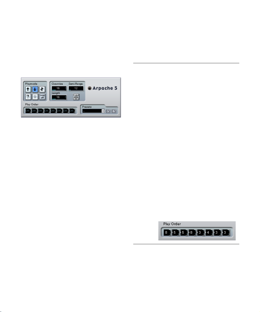
Introduction
This chapter describes the included MIDI realtime effects
and their parameters.
How to apply and handle MIDI effects is described in the
chapter “MIDI realtime parameters and effects” in the Operation Manual.
Arpache 5
A typical arpeggiator accepts a chord (a group of MIDI
notes) as input, and plays back each note in the chord
separately, with the playback order and speed set by the
user. The Arpache 5 arpeggiator does just that, and more.
Before describing the parameters, let’s look at how to create a simple, typical arpeggio:
1. Select a MIDI track and activate monitoring (or record
enable it) so that you can play “thru” the track.
Check that the track is properly set up for playback to a suitable MIDI instrument.
2. Select and activate the arpeggiator.
For now, use it as an insert effect for the selected track.
3. In the arpeggiator panel, use the Quantize setting to
set the arpeggio speed.
The speed is set as a note value, relative to the project tempo. For example, setting Quantize to “16” means the arpeggio will be a pattern of sixteenth notes.
4. Use the Length setting to set the length of the arpeg-
gio notes.
This allows you to create staccato arpeggios (Length smaller than the
Quantize setting) or arpeggio notes that overlap each other (Length
greater than Quantize).
5. Set the Semi-Range parameter to 12.
This will make the notes arpeggiate within an octave.
6. Play a chord on your MIDI instrument.
Now, instead of hearing the chord, you will hear the notes of the chord
played one by one, in an arpeggio.
7. Try the different arpeggio modes by clicking the Playmode buttons.
The symbols on the buttons indicate the playback order for the notes (up,
down, up+down, etc.). The Play Order settings are described below.
Parameters
The Arpache 5 has the following settings:
Setting Description
Playmode
buttons
Quantize Determines the speed of the arpeggio, as a note value re-
Length Sets the length of the arpeggio notes, as a note value re-
Semi-Range Determines the arpeggiated note range, in semitones
Thru If this is activated, the notes sent to the arpeggiator (i.e.
Play Order If the “Order on” playmode is selected, you can use these
Allows you to select the playback order for the arpeggiated notes. The options are down+up, up+down, up,
down, random (“?” button) and “Order off”, in which case
you can set the playback order manually with the Play Order fields below.
lated to the project tempo. The range is 32T (1/32 note
triplets) to “1.” (dotted note values).
lated to the project tempo. The range is the same as for
the Quantize setting.
counted from the lowest key you play. This works as follows:
– Any notes you play that are outside this range will be
transposed in octave steps to fit within the range.
– If the range is more than one octave, octave-transposed copies of the notes you play will be added to the
arpeggio (as many octaves as fit within the range).
the chord you play) will be passed through the plug-in
(sent out together with the arpeggiated notes).
“slots” to specify a custom playback order for the arpeggio notes:
Each slot corresponds to a position in the arpeggio pattern. For each slot, you specify which note should be
played on that position by selecting a number. The numbers correspond to the keys you play, counted from the
lowest pressed key.
So, if you play the notes C3-E3-G3 (a C major chord),
“1” would mean C3, “2” would mean E3, and “3” would
mean G3. Note that you can use the same number in several slots, creating arpeggio patterns that are not possible using the standard play modes.
76
MIDI effects
Page 77

Arpache SX
This is an even more versatile and advanced arpeggiator,
capable of creating anything from traditional arpeggios to
complex, sequencer-like patterns. The Arpache SX has
the following parameters:
Parameter Description
Arp Style Determines the basic behavior of the Arpache SX. In the
Quantize Determines the resolution of the arpeggio, i.e. its “speed”.
Length Determines the length of the arpeggio notes. The
Transpose When a mode other than “Off” is selected, the arpeggio
Play Mode See the description of Seq mode below!
Trigger Mode See the description of Seq mode below!
Velocity Source Determines the velocity of the notes in the arpeggio. The
Thru If this is activated, the notes sent to the arpeggiator (i.e.
Seq mode, the arpeggiator uses an imported MIDI part
as a starting point for the pattern – this is described below. All other modes describe how the notes in the chord
you play should be arpeggiated – up, down, up & down,
mostly up or mostly down.
The “Source” setting is used in Seq mode, see below.
“Source” setting is used in Seq mode, see below.
will be expanded upwards, downwards or both (depending on the mode). This is done by adding transposed repeats of the basic arpeggio pattern. The “Octave” setting
sets the number of transposed repeats and the “SemiSteps” setting determines how much each repeat will be
transposed.
options are Seq (used in Seq mode only), Input (the
same as the velocity values of the corresponding notes in
the chord you play) or Fixed, in which case all arpeggio
notes will get the velocity set in the value field to the right.
the chord you play) will be passed through the plug-in
(sent out together with the arpeggiated notes).
Parameter Description
Poly Determines how many notes should be accepted in the
Sort Mode When you play a chord into the Arpache SX, the arpeg-
input chord. The “All” setting means there are no limitations.
giator will look at the notes in the chord as sorted in the
order specified here. For example, if you play a C-E-G
chord, with “Note Lowest” selected, C will be the first
note, E will be the second and G the third. This affects
the result of the Arp Style setting.
Seq mode
When Seq mode is selected in the Arp Style section, the
Arpache SX uses an additional MIDI part as a pattern. This
pattern then forms the basis for the arpeggio, in conjunction with the MIDI input.
• To import a MIDI part into the Arpache SX, drag it from
the Project window and drop it in the “Drop a MIDI Part”
section on the Arpache SX.
Now, the notes in the dropped MIDI part will be sorted internally, either according to their pitch (“Sort Phrase by
Pitch” checkbox activated) or according to their play order
in the part. This results in a list of numbers. For example, if
the notes in the MIDI part are C E G A E C and they are
sorted according to pitch, the list of numbers will read 1 2
3 4 2 1. Here, there are 4 different notes/numbers and 6
trigger positions.
Now the MIDI input (the chord you send into the Arpache
SX) will also generate a list of numbers, with each note in
the chord corresponding to a number depending on the
Sort Mode setting.
The two lists of numbers will now be matched – the Arpache SX tries to play back the pattern from the dropped
MIDI file but using the notes from the MIDI input (chord).
The result depends on the Trigger Mode setting:
Trigger Mode Description
Trigger The whole pattern from the dropped MIDI file will be
Trigger Cnt. As above, but even when all keys are released, the
played back, but transposed according to one of the
notes in the MIDI input. Which note is used for transposing depends on the Sort Mode setting.
phrase continues playing from the last position (where it
stopped), when a new key is pressed on the keyboard.
This is typically used when playing “live” through the Arpache SX.
77
MIDI effects
Page 78

Trigger Mode Description
Sort Normal Matches the notes in the MIDI input to the notes in the
Sort First As above, but if there are fewer notes in the MIDI input,
Sort Any As above, but if there are fewer notes in the MIDI input,
Arp. Style As above, but if there are fewer notes in the MIDI input,
dropped MIDI part. If there are fewer notes (numbers) in
the MIDI input, some steps in the resulting arpeggio will
be empty.
the missing notes will be replaced by the first note.
the missing notes will be replaced by any (random) note.
the missing notes will be replaced by the last valid note in
the arpeggio.
Finally, the Play Mode setting affects the resulting arpeggio.
Note also that you can choose to keep the original note timing, note length and note velocities from the dropped MIDI
part, by selecting “Source” in the Quantize and Length
fields, and “Seq” in the Velocity Source section.
Waveform selectors
These determine the shape of the controller curves sent
out. The results of most of these waveforms are obvious
from looking at the buttons, but a few of them require
some extra explanations:
This generates a “random” controller curve.
These generate curves with a “periodical envelope”. The amplitude will
gradually increase or decrease over a time, set with the Period parameter (see below).
Autopan
This plug-in works a bit like an LFO in a synthesizer, allowing you to send out continuously changing MIDI controller
messages. One typical use for this is automatic MIDI panning (hence the name), but you can select any MIDI Continuous Controller event type. The Autopan effect has the
following parameters:
Period
This is where you set the speed of the Autopan, or rather
the length of a single controller curve cycle. The value can
be set in ticks (1/480ths of quarter notes), or as rhythmically exact note values (by clicking the arrow buttons next
to the value). The lower the note value, the slower the
speed. For example, if you set this to 240 (“8th”) the
waveform will be repeated every eighth note.
Density
This determines the density of the controller curves sent
out. The value can be set in ticks (1/480ths of quarter
notes), or as rhythmically exact note values (by clicking the
arrow buttons next to the value). The higher the note value,
the smoother the controller curve. For example, if you set
this to 60 (shown as “32th”) a new controller event will be
sent out every 60th tick (at every 1/32 note position).
!
You should probably avoid extremely low Density values, as these will generate a very large number of
events (which may cause the MIDI instrument to
“choke”, delaying notes etc.).
78
MIDI effects
Page 79

AmpMod
This is only used for the two waveforms with “periodical
envelopes” (see above). The period value (set in beats)
determines the length of the envelope. In the following figure, Period is set to 4th and the AmpMod is 4 beats. This
results in a quarter note-based curve in which the top amplitude decreases gradually, repeated each bar.
Controller
Determines which Continuous Controller type is sent out.
Typical choices would include pan, volume and brightness
but your MIDI instrument may have controllers mapped to
various settings, allowing you to modulate the synth parameter of your choice – check the MIDI implementation
chart for your instrument for details!
Min and Max
These determine the minimum and maximum controller
values sent out, i.e. the “bottom” and “top” of the controller curves.
Chorder
The Chorder is a MIDI chord processor, allowing you to assign complete chords to single keys in a multitude of variations. There are three main modes of operation: Normal,
Octave and Global. You switch between these modes by
clicking the respective button to the left below the keyboard.
1. Select the key to which you want to assign a chord, by
clicking in the lower “Trigger Note” keyboard display.
2. Set up the desired chord for that key by clicking in the
upper “Chord Setup” keyboard display.
Clicking a key adds it to the chord; clicking it again removes it.
3. Repeat the above with any other keys you wish to use.
If you now play the keys you have set up, you will instead
hear the assigned chords.
Octave mode
The Octave mode is similar to the Normal mode, but you
can only set up one chord for each key in an octave (that
is, twelve different chords). When you play a C note (regardless of whether it’s a C3, C4 or any other octave) you
will hear the chord set up for the C key.
Global mode
Normal mode
In this mode, you can assign a different chord to each single key on the keyboard. Proceed as follows:
MIDI effects
In the Global mode, you only set up a single chord, using
the Chord Setup keyboard display (the lower keyboard display is hidden). This chord is then played by all keys on the
keyboard, but transposed according to the note you play.
79
Page 80

Using switches
The Switch Setup section at the bottom of the panel allows you to set up variations to the defined chords. This
works with all three modes and provides a total of eight
variations for each assignable key (that is, a maximum of 8
different chords in Global mode, 12 x 8 chords in Octave
mode and 128 x 8 chords in Normal mode).
The variations can be controlled by velocity or note range.
Here’s how you set it up:
1. Select one of the two switch modes: velocity or note.
How to use these is explained below.
The velocity switch mode selected.
2. Specify how many variations you want to use with the
Use value box.
3. Click the first Switch Select button and set up the
chord(s) you want for the first variation.
4. Click the next Switch Select button and set up the
chord(s) you want for that variation.
5. Repeat this for the number of variations you specified
with the Use setting.
Each Switch Select button corresponds to a variation.
6. Now you can play the keyboard and control the varia-
tions according to the selected switch modes.
These work as follows:
Switch mode Description
Velocity The full velocity range (1–127) is divided into “zones”,
Note In this mode, the chorder will play one chord at a time –
according to the number of variations you specified. For
example, if you’re using two variations (Max is set to 2)
there will be two velocity “zones”: 1–63 and 64–127.
Playing a note with velocity at 64 or higher will trigger the
second variation, while playing a softer note will trigger
the first variation.
you cannot play several different chords simultaneously.
When the Note switch mode is selected, you play a key to
determine the base note for the chord, then press a higher
key to select a variation. The variation number will be the
difference between the two keys. To select variation 1,
press a key one semitone higher than the base note, for
variation 2, press a key two semitones higher, and so on.
Compress
This MIDI compressor is used for evening out or expanding
differences in velocity. Though the result is similar to what
you get with the Velocity Compression track parameter, the
Compress plug-in presents the controls in a manner more
like regular audio compressors. The parameters are:
Parameter Description
Threshold Only notes with velocities over this value will be affected
Ratio This determines the rate of compression applied to the
Gain This adds or subtracts a fixed value from the velocities.
by the compression/expansion.
velocity values above the threshold level. Ratios greater
than 1:1 result in compression (i.e. less difference in velocity) while ratios lower than 1:1 result in expansion (i.e.
greater difference in velocity).
What actually happens is that the part of the velocity
value that is above the threshold value is divided by the
ratio value.
Since the maximum range for velocity values is 0–127,
you may need to use the Gain setting to compensate,
keeping the resulting velocities within the range. Typically, you would use negative Gain settings when expanding and positive Gain settings when compressing.
• To turn the variation switch feature off, select the “No
Switch” mode.
80
MIDI effects
Page 81

Context Gate
The Context Gate allows for selective triggering/filtering
of MIDI data. It can be used for context selective control of
MIDI devices. The following parameters are available:
Poly Mode – Chord Gate
When Chord Gate is activated, only notes in recognized
chords are let through. There are two modes of chord recognition available; Simple and Normal. In Simple mode, all
standard chords (major/minor/b5/dim/sus/maj7 etc.) are
recognized, whereas Normal mode also takes more tensions into account.
Poly Mode – Polyphony Gate
This allows you to filter MIDI according to the number of
pressed keys within a given key range. This can be used
independently or in conjunction with the Chord Gate function.
• The Minimum value field allows you to specify the mini-
mum number of notes needed for the notes to be let
through.
• The Upper/Lower Range sets the key range.
Only notes within this range will be let through.
Mono Mode – Channel Gate
When this is activated, only single note events in a specified MIDI channel are let through, which can be used with
MIDI controllers that can send MIDI over several channels
simultaneously, for example guitar controllers which send
data for each string over a separate channel. You can either set this to a specific channel (1–16), or to “Any”, i.e.
no channel gating.
Mono Mode – Key Range Gate
This can be used independently or in conjunction with the
Channel Gate function. Played notes will sound (no note
off message) until a note is played inside the set Upper
and Lower range (and additionally the set Channel Gate
channel, if checked).
Panic button
Sends an “All Notes Off” message over all channels, in
case of hanging notes.
Learn button
When this is activated, you can specify a Reset trigger
event via MIDI. Whenever this specific MIDI event is sent,
it triggers an “All Notes Off” message. When you have set
the Reset event, the Learn button should be deactivated.
Auto Release time
If there is no input activity, all resounding notes are sent a
note off message after the set time, in seconds or milliseconds.
Minimum Velocity
Notes below a set velocity threshold value will be gated.
81
MIDI effects
Page 82

Density
This generic control panel affects the “density” of the
notes being played from (or thru) the track. When this is
set to 100%, the notes are not affected. Lowering the
Density setting below 100% will randomly filter out or
“mute” notes. Raising the setting above 100% will instead
randomly add new notes.
Micro Tuner
The Micro Tuner lets you set up a different microtuning
scheme for the instrument, by detuning each key.
• Each Detune field corresponds to a key in an octave (as indicated by the keyboard display). Adjust a Detune field to raise
or lower the tuning of that key, in cents (hundreds of a semitone).
• Set the Convert setting according to whether the track is
routed to a VST instrument or a “real” standard MIDI instrument (capable of receiving microtuning information).
The Micro Tuner comes with a number of presets, including both classical and experimental microtuning scales.
MIDIControl
This generic control panel allows you to select up to eight
different MIDI controller types, and use the value fields or
sliders (which are displayed when you click on a value field
while holding down the [Alt]/[Option] key) to set values for
these. A typical use for this would be if you’re using a MIDI
instrument with parameters that can be controlled by MIDI
controller data (e.g. filter cutoff, resonance, levels, etc.). By
selecting the correct MIDI controller types, you can use the
plug-in as a control panel for adjusting the sound of the instrument from within Cubase, at any time.
• To select a controller type, use the pop-up menus to the right.
• To deactivate a controller slider, set it to “Off” (drag the slider
all the way down).
82
MIDI effects
Page 83

MIDIEcho
This is an advanced MIDI Echo, which will generate additional echoing notes based on the MIDI notes it receives.
It creates effects similar to a digital delay, but also features
MIDI pitch shifting and much more. As always it is important to remember that the effect doesn’t “echo” the actual
audio, but the MIDI notes which will eventually produce
the sound in the synthesizer.
The following parameters are available:
Quantize
The echoed notes will be moved in position to a quantizing
grid, as set up with this parameter. You can either use the
slider or type to set the value in ticks (1/480 ticks of quarter notes) or click the arrow buttons to step between the
“rhythmically exact” values (displayed as note values – see
the table below). This makes it easy to find rhythmically
relevant quantize values, but still allows experimental settings in between.
An example: setting this to “16th” will force all echo notes
to be played on exact 16th note positions, regardless of
the timing of the original notes and the Echo-Quant. setting.
Ö To disable quantizing, set this parameter to its lowest
value (1).
Length
This sets the length of the echoed notes. This can either
be the same as their original notes (parameter set to its
lowest value, “Source”) or the length you specify manually.
You can either set the length in ticks or click the arrow
buttons to step between the “rhythmically exact” lengths
(displayed as note values – see the table below).
Ö The length can also be affected by the Length Decay
parameter.
Repeat
This is the number of echoes (1 to 12) from each incoming note.
Echo-Quant.
The Echo-Quant. parameter sets the delay time, i.e. the
time between a played note and its first echo note. You can
either use the slider or type to set the value in ticks (1/480
ticks of quarter notes) or click the arrow buttons to step between the “rhythmically exact” delay times (displayed as
note values – see the table below).
For example, setting this to “8th” will cause the echo
notes to sound an eighth note after their original notes.
Ö The echo time can also be affected by the Echo Decay
parameter.
Velocity Decay
This parameter allows you to add or subtract to the velocity values for each repeat so that the echo fades away or
increases in volume (provided that the sound you use is
velocity sensitive). For no change of velocity, set this to 0
(middle position).
Pitch Decay
If you set this to a value other than 0, the repeating (echoing) notes will be raised or lowered in pitch, so that each
successive note has a higher or lower pitch than the previous. The value is set in semitones.
For example, setting this to -2 will cause the first echo
note to have a pitch two semitones lower than the original
note, the second echo note two semitones lower than the
first echo note, and so on.
Echo Decay
This parameter lets you adjust how the echo time should
be changed with each successive repeat. The value is set
as a percentage.
• When set to 100% (middle position) the echo time will be the
same for all repeats (as set with the Echo-Quant. parameter).
• If you raise the value above 100, the echoing notes will play with
gradually longer intervals (i.e. the echo will become slower).
• If you lower the value below 100, the echoing notes will become gradually faster, like the sound of a bouncing ball.
83
MIDI effects
Page 84

Length Decay
This parameter lets you adjust how the length of the echoed notes should change with each successive repeat.
The higher the setting (25 –100), the longer the echoed
notes will be compared to their original notes.
Note to CC
About ticks and note values
The timing and position-related parameters (Echo-Quant.,
Length and Quantize) can all be set in ticks. There are 480
ticks to each quarter note. While the parameters allow you
to step between the rhythmically relevant values (displayed as note values), the following table can also be of
help, showing you the most common note values and their
corresponding number of ticks:
Note Value Ticks
1/32 note 60
1/16 note triplet 90
1/16 note 120
1/8 note triplet 160
1/8 note 240
Quarter note triplet 320
Quarter note 480
Half note 960
This effect will generate a MIDI continuous controller event
for each incoming MIDI note. The value of the controller
event corresponds to the note number (pitch) and the single parameter allows you to select which MIDI controller
should be sent out (by default controller 7, MIDI volume).
The incoming MIDI notes pass through the effect unaffected.
For example, if MIDI volume (controller 7) is selected,
notes with low note numbers (pitches) will lower the volume in the MIDI instrument, while higher note numbers will
raise the volume. This way you can create “keyboard
tracking” of volume or other parameters.
!
Note that a controller event is sent out each time a
new note is played. If high and low notes are played
simultaneously, this could lead to somewhat confusing results. Therefore, the Note to CC effect is probably best applied to monophonic tracks (playing one
note at a time).
84
MIDI effects
Page 85

Quantizer
Quantizing is a function that changes the timing of notes
by moving them towards a “quantize grid”. This grid may
consist of e.g. straight sixteenth notes (in which case the
notes would all get perfect sixteenth note timing), but
could also be more loosely related to straight note value
positions (applying a “swing feel” to the timing, etc.).
Ö The main Quantize function in Cubase is described in
the Operation manual.
While the Quantize function on the MIDI menu applies the
timing change to the actual notes on a track, the Quantizer
effect allows you to apply quantizing “on the fly”, changing
the timing of the notes in real time. This makes it easier to
try out different settings when creating grooves and
rhythms. Note however, that the main Quantize function
contains settings and features that are not available in the
Quantizer.
The Quantizer has the following parameters:
Parameter Description
Quantize Note This sets the note value on which the quantize grid is
Swing This allows you to offset every second position in the
Strength This determines how close the notes should be moved to
Delay This delays (positive values) or advances (negative val-
based. Straight notes, triplets and dotted notes are available. For example, “16” means straight sixteenth notes
and “8T” means eighth note triplets.
grid, creating a swing or shuffle feel. The value is a percentage – the higher you set this, the farther to the right
every even grid position is moved.
the quantize grid. When set to 100%, all notes will be
forced to the closest grid position; lowering the setting
will gradually loosen the timing.
ues) the notes in milliseconds. Unlike the Delay setting in
the Track Parameters, this delay can be automated.
Step Designer
The Step Designer is a MIDI pattern sequencer that sends
out MIDI notes and additional controller data according to
the pattern you set up. It does not make use of the incoming MIDI, other than automation data (such as recorded
pattern changes).
Creating a basic pattern
1. Use the Pattern selector to choose which pattern to
create.
Each Step Designer can hold up to 200 different patterns.
2. Use the Quantize setting to specify the “resolution” of
the pattern.
In other words, this setting determines how long each step is. For example, if Quantize is set to “16th” each step will be a sixteenth note.
3. Specify the number of steps in the pattern with the
Length setting.
As you can see in the note display, the maximum number of steps is 32.
For example, setting Quantize to 16 and Length to 32 would create a
two bar pattern with sixteenth note steps.
4. Click in the note display to insert notes.
You can insert notes on any of the 32 steps, but the Step Designer will
only play back the number of steps set with the Length parameter.
• The display spans one octave (as indicated by the pitch
list to the left). You can scroll the displayed octave up or
down by clicking in the pitch list and dragging up or down.
This way you can insert notes at any pitch. Note that each step can contain
one note only – the Step Designer is monophonic.
Click and drag to view other octaves.
• To remove a note from the pattern, click on it again.
85
MIDI effects
Page 86

5. Select “Velocity” on the Controllers pop-up menu.
This pop-up menu determines what is shown in the lower controller display.
6. Adjust the velocity of the notes by dragging the velocity bars in the controller display.
7. To make notes shorter, select “Gate” on the Controllers
pop-up menu and lower the bars in the controller display.
When a bar is set to its maximum value (fully up), the corresponding note
will be the full length of the step (as set with the Quantize parameter).
8. To make notes longer, you can tie two notes together.
This is done by inserting two notes and clicking the Tie
button below the second note.
When the Tie button is lit for a note, it won’t retrigger – instead the previous note will be lengthened. Also, the tied (second) note will automatically get the same pitch as the first note. You can add more notes and tie
them in the same way, creating longer notes.
9. If you now start playback in Cubase, the pattern will
play as well, sending out MIDI notes on the track’s MIDI
output and channel (or, if you have activated the Step Designer as a send effect, on the MIDI output and channel
selected for the send in the Inspector).
Adding controller curves
The Controllers pop-up menu has two more items: two
controller types.
• You can select which two controller types (filter cutoff,
resonance, volume, etc.) should be available on the popup menu by clicking the Setup button and selecting controllers from the lists that appears.
This selection is global to all patterns.
• To insert controller information in a pattern, select the
desired controller from the pop-up menu and click in the
controller display to draw events.
The MIDI controller events will be sent out during playback along with the
notes.
Ö If you drag a controller event bar all the way down, no
controller value will be sent out on that step.
Other pattern functions
The following functions make it easier to edit, manipulate
and manage patterns:
Function Description
Shift Oct These buttons allow you to shift the entire pattern up or
Shift Time Moves the pattern one step to the left or right.
Reverse Reverses the pattern, so that it plays backwards.
Copy/Paste Allows you to copy the current pattern and paste it in an-
Reset Clears the pattern, removing all notes and setting con-
Random Generates a completely random pattern – useful for ex-
Swing The Swing parameter allows you to offset every second
Presets Handling of Presets is described in the chapter “MIDI re-
down in octave steps.
other pattern location (in the same Step Designer or another).
troller values to default.
perimenting.
step, creating a swing or shuffle feel. The value is a percentage – the higher you set this, the farther to the right
every even step is moved.
altime settings” in the Operation manual. Note that a
stored Preset contains all 200 patterns in the Step Designer.
Automating pattern changes
You can create up to 200 different patterns in each Step
Designer – just select a new pattern and add notes and
controllers as described above.
Typically, you want the pattern selection to change during
the project. You can accomplish this by automating the Pattern selector, either in real time by activating the Write automation and switching patterns during playback or by
drawing in the automation subtrack for the Step Designer’s
MIDI track. Note that you can also press a key on your MIDI
keyboard to change patterns. For this, you have to set up
the Step Designer as an insert effect for a record enabled
MIDI track. Press C1 to select pattern 1, C#1 to select pattern 2, D1 to select pattern 3, D#1 to select pattern 4 and
so on. If you want, you can record these pattern changes as
note events on a MIDI track. Proceed as follows:
1. Select the desired MIDI track or create a new one and
activate the Step Designer as an insert effect.
2. Set up several patterns as described above.
86
MIDI effects
Page 87

3. Press the Record button and press the desired keys
on your keyboard to select the corresponding patterns.
The pattern changes will be recorded on the MIDI track.
4. Stop recording and play back the MIDI track.
You will now hear the recorded pattern changes.
Ö This will only work for the first 92 patterns.
Track Control
Selecting a control panel
At the top of the Track Controls effect window you will
find a pop-up menu. This is where you select which of the
available control panels to use:
Control panel Description
GS Basic
Controls
XG Effect +
Sends
XG Global Global settings (affecting all channels) for instruments
Effect sends and various sound control parameters for
use with instruments compatible with the Roland GS
standard.
Effect Sends and various sound control parameters for
use with instruments compatible with the Yamaha XG
standard.
compatible with the Yamaha XG standard.
About the Reset and Off buttons
Regardless of the selected mode, you will find two buttons
labelled “Off” and “Reset” at the top of the control panel:
• Clicking the Off button will set all controls to their low-
est value, without sending out any MIDI messages.
• Clicking the Reset button will set all parameters to their
default values, and send out the corresponding MIDI messages.
For most parameters, the default values will be zero or “no adjustment”,
but there are exceptions to this. For example, the default Reverb Send
settings are 64.
The Track Control effect contains three ready-made control panels for adjusting parameters on a GS or XG compatible MIDI device. The Roland GS and Yamaha XG
protocols are extensions of the General MIDI standard, allowing for more sounds and better control of various instrument settings. If your instrument is compatible with
GS or XG, the Track Controls effect allows you to adjust
sounds and effects in your instrument from within Cubase.
MIDI effects
87
Page 88

GS Basic Controls
The following controls are available when the GS Basic
Controls mode is selected:
Control Description
Send 1 Send level for the reverb effect.
Send 2 Send level for the chorus effect.
Send 3 Send level for the “variation” effect.
Attack Adjusts the attack time of the sound. Lowering the value
Decay Adjusts the decay time of the sound. Lowering the value
Release Adjusts the release time of the sound. Lowering the value
Cutoff Adjusts the filter cutoff frequency.
Resonance Adjusts the filter resonance.
Express Allows you to send out expression pedal messages on
Press. Allows you to send out aftertouch (channel pressure)
Breath Allows you to send breath control messages on the
Modul. Allows you to send modulation messages on the track’s
shortens the attack, while raising it gives a slower attack.
Middle position (64) means no adjustment is made.
shortens the decay, while raising it makes the decay
longer.
shortens the release, while raising it makes the release
time longer.
the track’s MIDI channel.
messages on the track’s MIDI channel. This is useful if
your keyboard cannot send aftertouch, but you have
sound modules that respond to aftertouch. The default
value for this parameter is zero.
track’s MIDI channel.
MIDI channel (just as you normally do with a modulation
wheel on a MIDI keyboard).
XG Effects + Sends
The following controls are available when the XG Effects
+ Sends mode is selected:
Control Description
Send 1 Send level for the reverb effect.
Send 2 Send level for the chorus effect.
Send 3 Send level for the “variation” effect.
Attack Adjusts the attack time of the sound. Lowering this value
Release Adjusts the release time of the sound. Lowering this value
Harm.Cont Adjusts the harmonic content of the sound.
Bright Adjusts the brightness of the sound.
CutOff Adjusts the filter cutoff frequency.
Resonance Adjusts the filter resonance.
shortens the attack, while raising it gives a slower attack.
Middle position means no adjustment is made.
shortens the release, while raising it makes the release
time longer. Middle position means no adjustment is
made.
XG Global Settings
In this mode, the parameters affect global settings in the
instrument(s). Changing one of these settings for a track
will in fact affect all MIDI instruments connected to the
same MIDI output, regardless of the MIDI channel setting
of the track. Therefore, to avoid confusion it might be a
good idea to create an empty track and use this only for
these global settings.
The following controls are available:
Control Description
Eff. 1 This allows you to select which type of reverb effect
Eff. 2 This allows you to select which type of chorus effect
Eff. 3 This allows you to select one of a large number of “varia-
Reset Sends an XG reset message.
MastVol This is used to control the Master Volume of an instru-
should be used: No effect (the reverb turned off), Hall 1–
2, Room 1–3, Stage 1–2 or Plate.
should be used: No effect (the chorus turned off), Chorus
1–3, Celeste 1–3 or Flanger 1–2.
tion” effect types. Selecting “No Effect” is the same as
turning off the variation effect.
ment. Normally you should leave this in its highest position and set the volumes individually for each channel
(with the volume faders in the Cubase mixer or in the
Inspector).
88
MIDI effects
Page 89
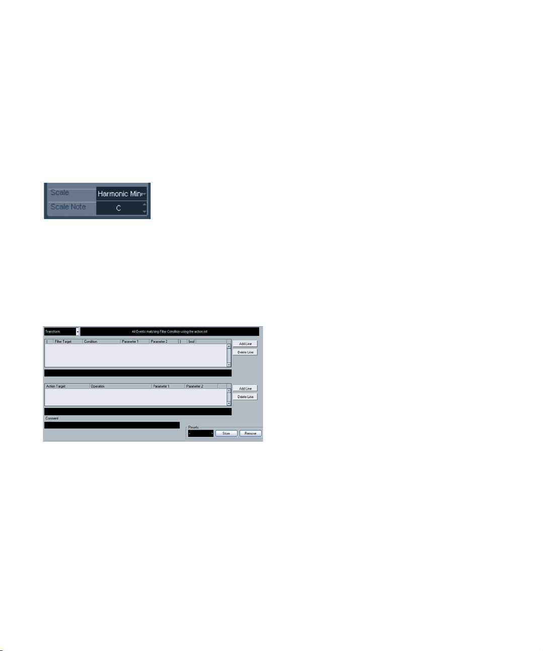
Track FX
This plug-in is essentially a duplicate of the Track Parameter section. This can be useful if you e.g. need extra Random or Range settings, or if you prefer to have your track
parameters in a separate window (to get this, [Alt]/[Option]-click the Edit button for the effect).
The Track FX also includes an additional function that isn’t
available among the track parameters:
Scale Transpose
This allows you to transpose each incoming MIDI note, so
that it fits within a selected musical scale. The scale is
specified by selecting a key (C, C#, D, etc.) and a scale
type (major, melodic or harmonic minor, blues, etc.).
Ö To turn Scale Transpose off, select “No Scale” from
the Scale pop-up menu.
Transformer
The Transformer is a real-time version of the Logical Editor.
With this you can perform very powerful MIDI processing
on the fly, without affecting the actual MIDI events on the
track.
The Logical Editor is described in the corresponding
chapter in the Operation Manual. As the parameters and
functions are almost identical, the descriptions for the
Logical Editor also apply to the Transformer. Where there
are differences between the two, this is clearly stated.
MIDI effects
89
Page 90

Index
Page 91

A
Apogee UV22 HR 25
Arpache 5 76
Arpache SX 77
Arpeggiator 76, 77
AutoPan 25
Autopan (MIDI effect) 78
B
Bitcrusher 32
C
Chopper 32
Chorder (MIDI effect) 79
Cloner 26
Compress (MIDI effect) 80
Compressor 10
D
DaTube 9
Density (MIDI Effect) 82
Dither 25
E
Embracer Synthesizer 69
EnvelopeShaper 12
Expander 12
F
Flanger 27
G
Gate 13
GEQ-10 19
GEQ-30 19
GS Control Panel 87
L
Limiter 14
M
Maximizer 14
Metalizer 27
Micro Tuner (MIDI Effect) 82
MIDI Context Gate (MIDI effect) 81
MIDI Echo (MIDI effect) 83
MIDI Step Sequencer 85
MIDIControl (MIDI Effect) 82
Mix6To2 37
ModMachine 6
MonoDelay 7
Monologue Synthesizer 71
MonoToStereo 36
MultibandCompressor 16
MultiScope 37
Mystic
Modulation parameters 62
Sound parameters 60
N
Note to CC (MIDI effect) 84
O
Octaver 33
P
Pattern Sequencer 85
Phaser 28
PingPongDelay 8
Prologue
Modulation parameters 47
Sound parameters 42
Q
Q 25
Quantizer (MIDI effect) 85
R
Ringmodulator 28
Roland GS Control Panel 87
RoomWorks 34
RoomWorks SE 35
Rotary 29
S
SMPTE Generator 39
SoftClipper 10
Spector
Modulation parameters 54
Sound parameters 52
SPL DeEsser 11
Step Designer (MIDI effect) 85
StepFilter 21
StereoDelay 8
StereoEnhancer 36
StudioChorus 30
StudioEQ 20
SurroundPan 37
T
ToneBooster 22
Tonic 23
Track Control (MIDI Effect) 87
Track FX (MIDI Effect) 89
Tranceformer 30
Tremolo 31
U
UV22 HR 25
V
Vintage compressor 17
VST Instruments
HALionOne 67
Mystic 60
Prologue 42, 60
Spector 52
VSTDynamics 17
X
XG Control Panel 87
Y
Yamaha XG Control Panel 87
91
Index
 Loading...