

Page 1
WARRANTY
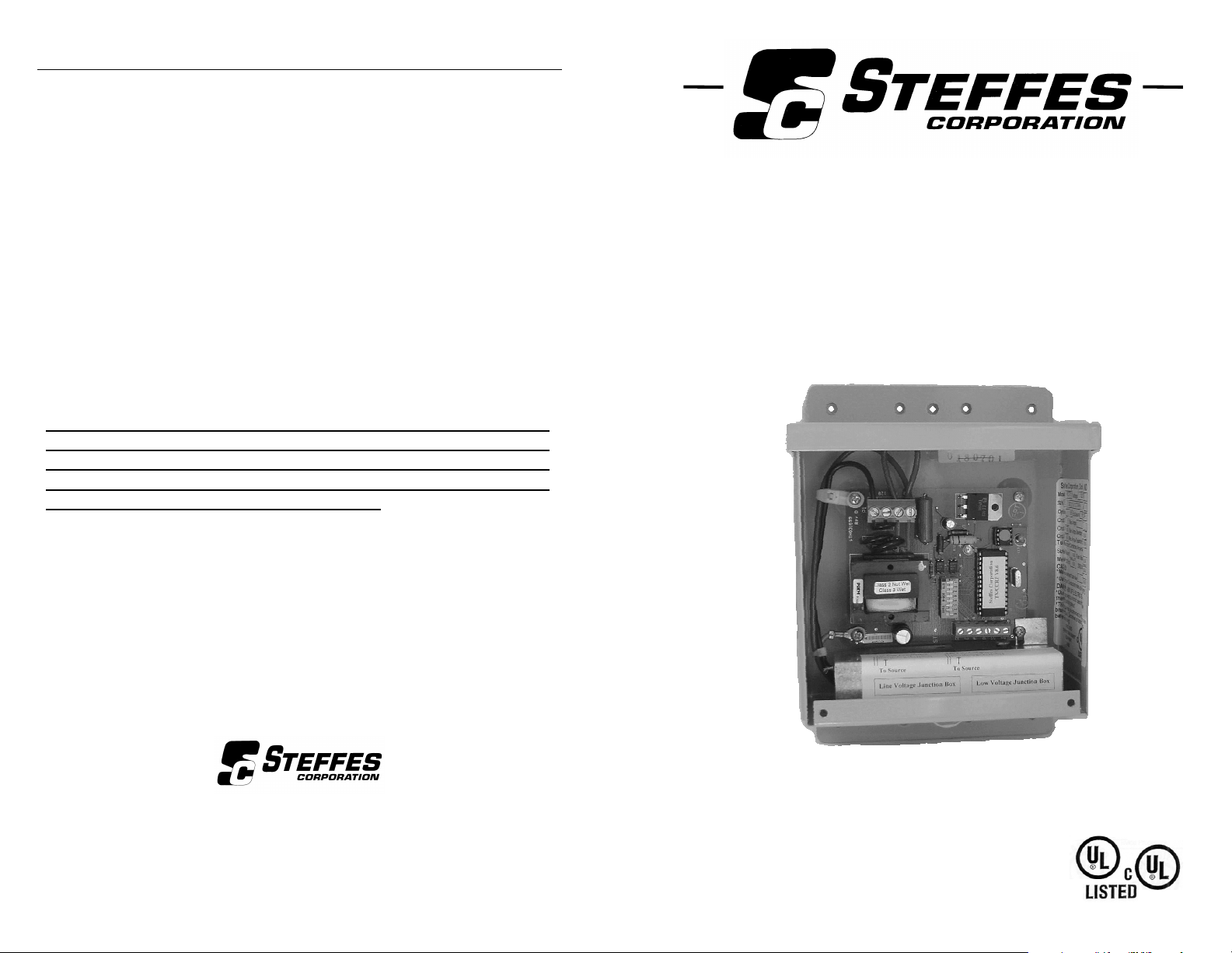
Steffes Corporation (“Steffes”) warrants that the Steffes Power Line
Carrier Transmitter is free from defects in materials and workmanship
under normal use and service. Steffes’ obligation under this Warranty is
limited to the repair or replacement of the appliance or parts only which
prove to be defective under normal use within one (1) year of the date of
installation and which Steffes’ examination of the returned device or
part(s) shall verify to Steffes’ satisfaction that it is defective. The user
shall be responsible for any labor costs associated with the repair or
replacement of the device or part(s) including the cost of returning the
defective appliance or part(s) to Steffes Corporation.
PLC8
“Commitment to Innovation”
Operation & Installation Guide
for
Power Line Carrier
This Warranty is void if the transmitter device is moved from the
premises in which it was originally installed. This Warranty shall not
apply to a device or part which has been altered in any respect, or
improperly installed, serviced or used, or has been subject to accident,
negligence, abuse or misuse.
THE ABOVE WARRANTY BY STEFFES IS EXCLUSIVE AND IN
LIEU OF ALL OTHER WARRANTIES, WHETHER WRITTEN
OR ORAL, EXPRESSED OR IMPLIED, INCLUDING ANY
IMPLIED WARRANTY OF MERCHANTABILITY OR OF
FITNESS FOR A PARTICULAR PURPOSE.
The user assumes all risk and liability whatsoever resulting from the use
of this transmitter. In no event shall Steffes be liable for any indirect,
special or consequential damages or lost profits.
This Limited Warranty contains the complete and exclusive statement of
Steffes’ obligations with respect to the transmitter and any parts thereof.
The provisions hereof may not be modified in any respect except in
writing signed by a duly authorized officer of Steffes.
Transmitter
(Applicable to Software Version 14.0-14.9)
3050 N Highway 22
Dickinson, ND 58601-9413
701-483-5400
“Commitment to Innovation”
“Manufactured in North America”
Off-Peak System Control
DOCUMENT #1200114
Page 2

Page 3
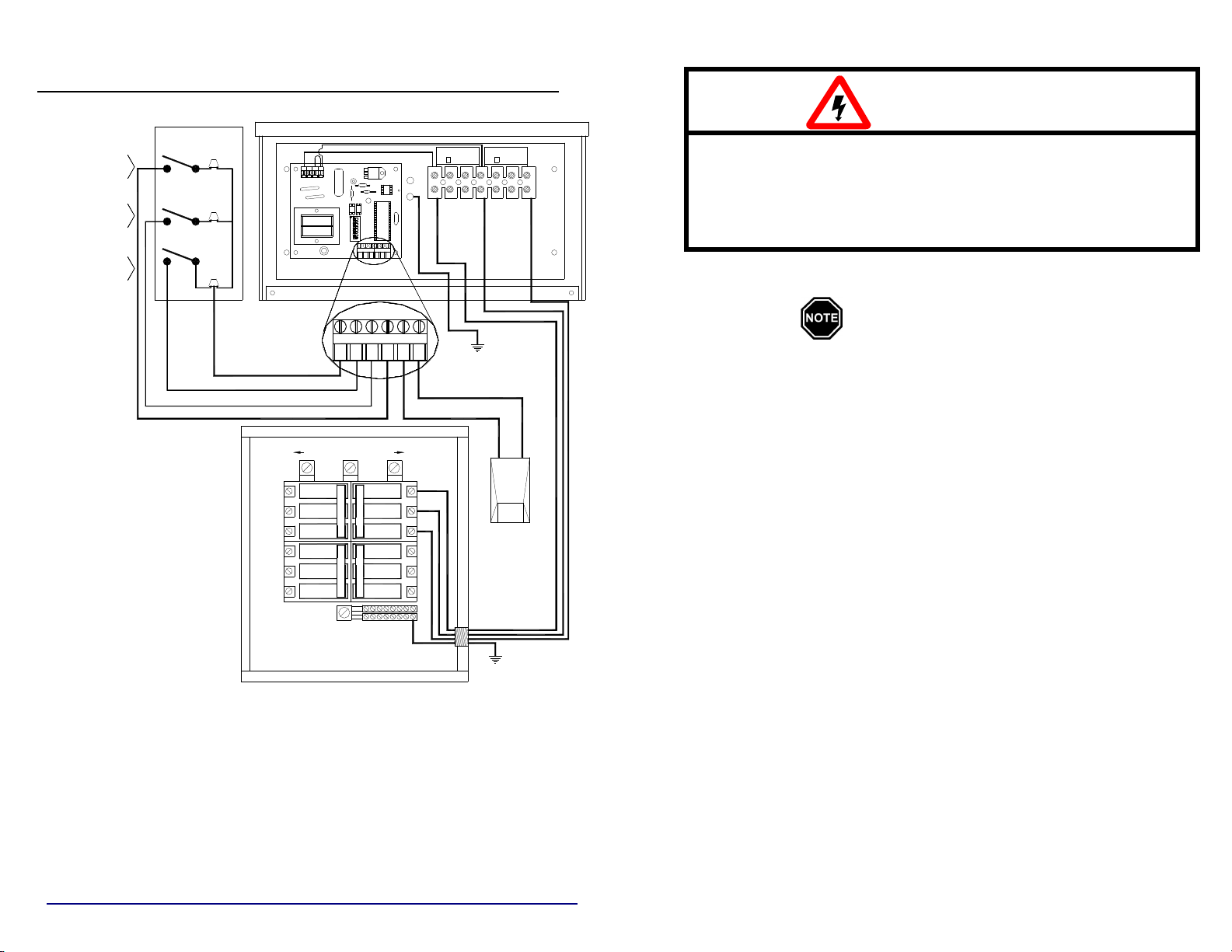
TYPICAL SYSTEM WIRING DIAGRAM
HAZARDOUS VOLTAGE: Risk of electric shock, injury, or
208/240 VOLT, 3-PHASE SYSTEMS ONLY
WARNING
Utility Peak
Control Switch.
Anticipated Peak Control
Switch. Only if being
Utilized By the
Power Company.
Room Temperature
Set-Back. ( Optional )
ROCKER DOWN
LOW VOLTAGE
CONNECTIONS
LOW VOLTAGE HOT
A-PEAK (OPTIONAL)
ROOM TEMP SETBACK (SPECIAL APPLICATIONS)
PEAK
R
3-PHASE
240/208VAC SOURCE
20A 3-PHASE
1
20A 3-PHASE
2
Service Panel
1 5 5 K
630V
.M .M
H.
1 5 5 K
630V
H.
death. System may be connected to more than one branch
N
O
2 31
4 5 6
7 8
LG
I
R
N
O
E
U
1
N
D
L
L
I
I
N
N
E
E
2
3
circuit. Disconnect power to all circuits before servicing.
Equipment must be installed and serviced by a qualified
technician.
IMPORTANT
OS
E
A
15A 3-PHASE
20A 3-PHASE
OS
P
w The equipment described herein is intended for installation by a
qualified technician in accordance with applicable local, state, and
national codes and requirements.
w This manual should be retained by the owner upon completion of the
installation and made available to service personnel as required.
w Disclaimer:
3
REMOTE
4
OUTDOOR
SENSOR
(OPTIONAL)
Conditions may occur which cause the power line carrier
transmitter and receivers to have difficulties communicating;
therefore, not operating properly. In no event shall Steffes
Corporation be liable for any indirect, special, or consequential
damages or lost profits.
In compiling this manual, Steffes Corporation has used its best
judgement based upon information available, but disclaims any
responsibility or liability for any errors or miscalculations
contained herein, or any revisions hereof, or which result, in
whole or in part, from the use of this manual or any revisions
hereof.
NOTES:
1. To ensure proper communications between the PLC transmitter and the
controllable electrical loads, the transmitter MUST be grounded.
2. The system grounding and bonding must be sized and installed in
compliance with all applicable codes.
3. The transmitter in this diagram is shown connected directly to the service
panel. However, any appropriately sized uninterrupted branch circuit
can be used to power the transmitter.
10
FOR CUSTOMER USE
Please record the serial number of the transmitter below. This information is
located inside the transmitter enclosure. Retain this information for future
reference.
Serial No.________________________________________________
Page 4
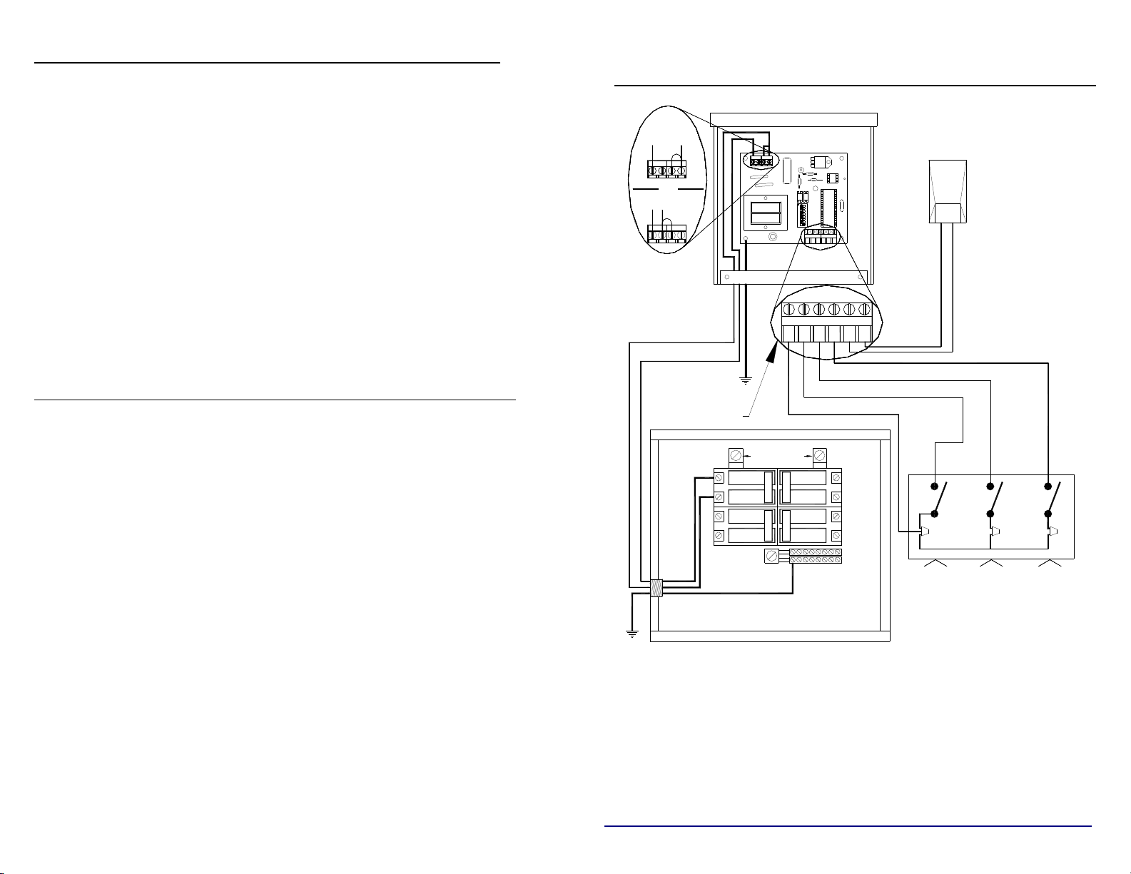
TABLE OF CONTENTS
General Operation ...................................................................1
Installation............................................................................ 1-4
Line Voltage Connections ............................................... 1-2
Peak Control ........................................................................2
Circuit Board Configuration ................................................2
Outdoor Temperature Sensor...............................................3
Indicator Lights....................................................................3
Room Temperature Set Back...............................................3
Anticipated Peak ..................................................................4
Dip Switch Settings .............................................................. 4-6
Installer’s Final Check Out Procedure .............................. 7-8
Typical System Wiring Diagram (Single Phase)...................9
Typical System Wiring Diagram (3-Phase).........................10
FEATURES
The PLC transmitter is an accurate and reliable device offering the
following features:
w Operates on 120V or 208V/240V, single phase.
w Pre-wired 16 AWG leads for line voltage field connections.
w A 6” x 6” x 3” rainproof metal enclosure with power company
seal/lockout provision for indoor or outdoor installations. A three
phase system in a 12” x 6” x 3” rainproof metal enclosure is
available as a special factory order.
w Fifteen (15) selectable communication channels.
w Wireless control of an unlimited number of Steffes microprocessor
based heating systems and any controllable devices with the
correlating receiver.
w Capable of transmitting:
é Peak Control Signals
é Outdoor Temperature Information (Automatic Charge Control)
é Room Temperature Set Back Information (requires an external
signaling device, not included)
é Anticipated Peak (pre-peak) Control Signals
TYPICAL SYSTEM WIRING DIAGRAM
SINGLE PHASE (208/240 Volt or 120 Volt)
LINE
VOLTAGE
CONNECTIONS
208/240V
OR
N
120V
LOW VOLTAGE
CONNECTIONS
240VAC SOURCE
1
2
Service Panel
O
ROCKER DOWN
21 45 6 7 83
OS
E
R
A
ROOM TEMP SETBACK (OPTIONAL)
LOW VOLTAGE HOT
20
20
2015
OS
P
A-PEAK (SPECIAL APPLICATIONS)
3
4
OUTDOOR
PEAK
NOTES:
1. To ensure proper communications between the PLC transmitter and the
controllable electrical loads, the transmitter MUST be grounded.
2. The system grounding and bonding must be sized and installed in
compliance with all applicable codes.
3. The transmitter in this diagram is shown connected directly to the service
panel. However, any appropriately sized uninterrupted branch circuit
can be used to power the transmitter
SENSOR
REMOTE
OUTDOOR
SENSOR
(OPTIONAL)
Room
Temperature
Set-Back
( Optional )
Anticipated Peak
Control Switch.
Only if being
Utilized By the
Power Company.
Utility Peak
Control Switch.
9
Page 5
INSTALLER’S FINAL CHECK OUT PROCEDURE CONTINUED….
WARNING
HAZARDOUS VOLTAGE: Risk
junction box.
GENERAL OPERATION
INTERFACING THE TRANSMITTER WITH THE STEFFES 1000
and 2000 SERIES ROOM HEATING UNITS:
All heater locations referenced below are accessed through
the faceplate on the front of the 1000/2000 Series heater.
Refer to the Owner's Manual for operating instructions.
____ 1. Verify that the heater is operating on the same channel as the
transmitter by checking the setting in Location 11 (L11) of the
____ 2. O
heater. The heater is factory preset to operate on channel 1.
nce good communication is established between the transmitter
and the heater, the lower right indicator light on the heater’s
faceplate illuminates green continuously.
____ 3. If utilizing the transmitter’s automatic charge control features,
compare the information in Location 46 (L46) of the heater’s
control circuit board to the actual outdoor temperature. This
location will display a hex value approximating the current
outdoor temperature. If the temperature information in L46 is
reading substantially higher or lower than actual outdoor
temperature, refer to Dip Switch Settings 7 and 8.
If the transmitter is installed indoors and automatic charge
control is desired, a remote outdoor sensor is required.
INTERFACING THE TRANSMITTER WITH THE STEFFES 2100
SERIES AND COMFORT PLUS SYSTEMS:
The "Help Menu" on the heater is accessed through the
faceplate on the front of the heater. Refer to the Owner's
and Installer's Manual for operating instructions.
The Steffes Power Line Carrier (PLC) Transmitter is a device used for
communicating information through the local electric circuits to an
unlimited number of Steffes microprocessor based heating systems
(1000, 2000, 2100, 3100, 4100, and 5100 Series) and other controllable
devices incorporating the Steffes PLC receiver. A receiver is built into
Steffes microprocessor based heating systems, so the transmitter can
communicate directly with the equipment without the cost of additional
controls or electrical wiring. Therefore, overall installation costs of an
ETS system can be significantly reduced, especially in multiple unit
installations and projects such as hotels, motels, apartments, condos, etc.
The transmitter must be wired into the line voltage power serving the
installation. The transmitter continuously sends information through the
local electric circuits. This information is received by the Steffes heating
equipment and other controllable devices with a correlating receiver,
provided they are on the same power company distribution transformer as
the transmitter.
INSTALLATION
Mount the transmitter in the desired location.
If utilizing the built-in outdoor temperature sensing
thermistor, it is important to place the transmitter in an area
where it will NOT be exposed to direct sunlight.
Line Voltage Connections
This device can be connected to 120V or 208V/240V, single phase.
Using the "Help Menu" on the heater’s control panel:
____ 1. Verify that the heater is operating on the same channel as the
transmitter. The 2100 Series heater is factory preset to operate
on channel 1. Comfort Plus systems are not factory preset for
power line carrier.
____ 2. Verify that power line carrier communication is occurring.
____ 3. If utilizing the transmitter’s automatic charge control features,
compare the outdoor temperature information from the "Help
Menu" to current outdoor temperature. If the temperature
information in the help menu is substantially higher or lower
than actual outdoor temperature, refer to Dip Switch Settings 7
and 8.
8
In most applications, optimum performance is achieved
when connected to 208V/240V.
The PLC transmitter is factory
configured for 208V/240V field
connections. DO NOT connect the
transmitter to 277V unless the
identification label indicates it is
suitable for 277V. A three-phase
option is available as a special order.
of electric shock, injury, or
death. All line voltage wiring
connections MUST be made
within and routed through the
line voltage raceway of the
transmitter’s factory installed
1
Page 6
INSTALLATION CONTINUED…
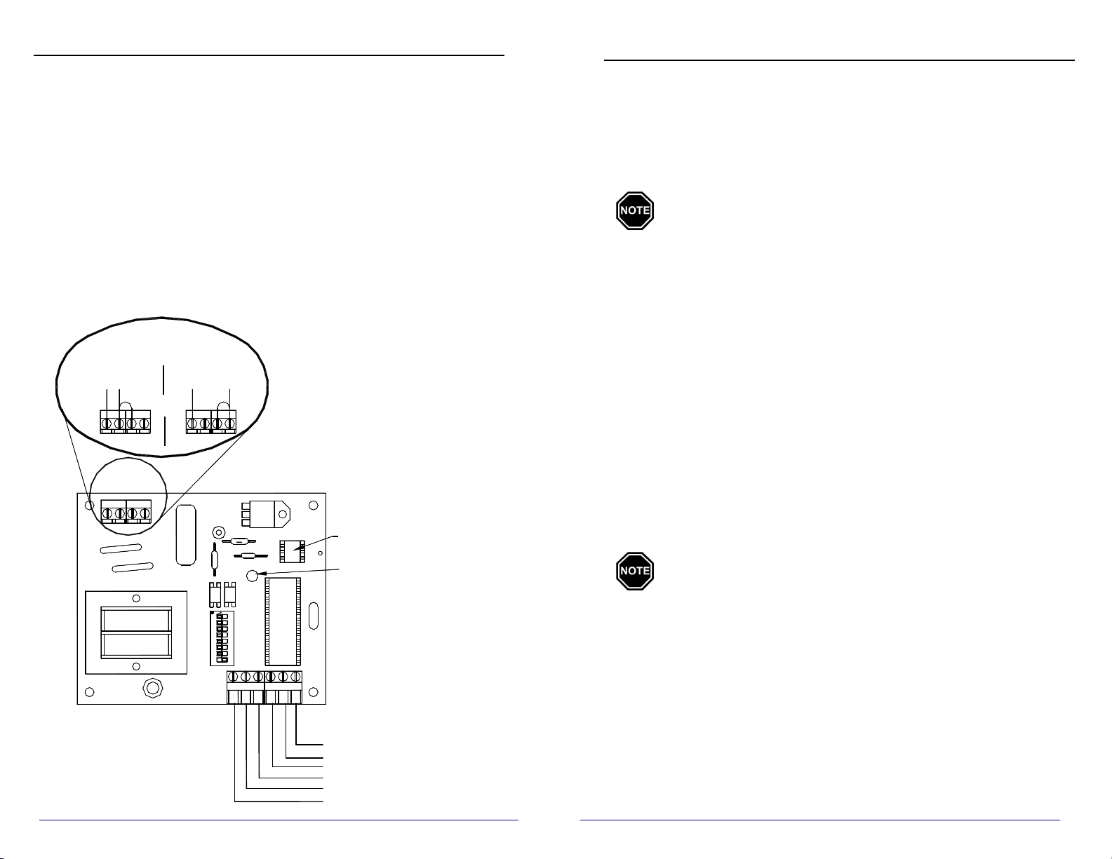
If the transmitter is to be connected to 120V, transformer tapping
MUST be changed. To change transformer tapping to 120V, move the
black wire jumper to positions P2 and 110 in the line voltage terminal
strip. Move the factory installed line voltage connections to the 110 and
L1 positions in the line voltage connections terminal strip. (See Circuit
Board Configuration below for reference to proper placement of the
jumper and wires.)
Peak Control
Connect the peak control signaling device to the "R" and "P" terminals
on the low voltage terminal strip.
INSTALLER’S FINAL CHECK OUT PROCEDURE
____ 1. Prior to energizing the electrical circuit feeding the transmitter,
inspect all field installed electrical connections to ensure they are
tight and all wires are routed correctly. All line voltage wiring
connections must be made within and routed through the line
voltage raceway of the factory-installed junction box. To ensure
proper communication, the transmitter must be grounded.
The transmitter is factory configured for 208V/240V field
connections. If using 120V input, transformer tapping must
be changed. (Refer to the Circuit Board Configuration
Diagram.)
Circuit Board Configuration
VOLTAGE CONNECTIONS
120V
L1 L2
LINE
208V/240V
L1
L2
OR
220
110
L1
P2
O
N
1 2 3 4
TRANSFORMER
ROCKER DOWN
5 6 7 8
____ 2. Make sure the dip switch settings on the transmitter are in the
correct positions for the application. Remember, the desired PLC
channel MUST be selected for communication to occur.
____ 3. Activate the utility peak control device and energize the
transmitter. Verify that the indicator light on the transmitter is
illuminated and corresponds with the utility peak signal (flashing
____ 4.
for off-peak or continuous illumination for on-peak).
Invert dip switch #1 on the transmitter. If the indicator light was
flashing in Step 3, it should now illuminate continuously. If the
light had been illuminated, it should now begin to flash. Return
dip switch #1 to the proper position for the application.
____ 5. Use the guidelines which follow to verify the transmitter is
communicating with all receivers in the application
MEMORY
CHIP
INDICATOR
MICROPROCESSOR
SOFTWARE
LIGHT
(microprocessor based heaters and Steffes mini receiver
configurations).
Communication between the transmitter and receiver
occurs on a continuous basis. Upon energizing a system,
there will be some delay in a receiver’s response to the
transmitter's signal. It takes approximately seven (7)
minutes to establish initial communication. Subsequent
communication will occur more rapidly.
INTERFACING THE TRANSMITTER WITH THE STEFFES MINI
Low Voltage
Terminal Strip Connections
OS - OUTDOOR SENSOR
OS - OUTDOOR SENSOR
P - PEAK CONTROL
A - ANTICIPATED PEAK
E - ROOM TEMP. SET BACK
R - LOW VOLTAGE HOT
2 7
RECEIVER (single, double or six pole configurations):
Once the mini receiver is receiving complete information from the
transmitter, the red indicator light on the mini receiver will illuminate
continuously. Refer to the Operation and Installation Guide for the Mini
Receiver to perform the checkout procedure for this device and ensure
correct installation and operation.
Page 7

DIP SWITCH SETTINGS CONTINUED….
INSTALLATION CONTINUED…
DIP SWITCH 6: NOT USED IN PLC TRANSMITTER
FACTORY DEFAULT SETTING = OFF
DIP SWITCH 7: NEGATIVE OUTDOOR TEMPERATURE
CALIBRATION
This dip switch is used to calibrate the outdoor temperature sensor
information DOWNWARD if it is reading HIGHER than the actual
outdoor temperature.
FACTORY DEFAULT SETTING = OFF
Off = Standard operating position.
On =
A negative 5oF (-5oF) outdoor temperature calibration will be applied.
DIP SWITCH 8: POSITIVE OUTDOOR TEMPERATURE
CALIBRATION
This dip switch is used to calibrate the outdoor temperature sensor
information UPWARD if it is reading LOWER than the actual outdoor
temperature.
FACTORY DEFAULT SETTING = OFF
Off = Standard operating position.
On =
A positive 5oF (+5oF) outdoor temperature calibration will be applied.
Outdoor Temperature Sensor
The outdoor sensor provides outdoor temperature information to the
transmitter which in turn sends these signals, wireless, to the microprocessor
based heating systems. The heater’ s brick core temperature target level
adjusts automatically in relation to outdoor temperature.
A temperature sensing thermistor is connected to the two “OS” positions of
the low voltage terminal strips for automatic charge control of ETS heaters.
This sensor can be utilized if the transmitter is mounted in a location where it
can accurately sense the outdoor temperature and will not be affected by
direct sunlight or other sources of heat and cold. The temperature sensor may
be affected by heat generation from inside the enclosure. However, in most
applications, it provides suitable outdoor temperature sensing.
If the transmitter is installed indoors and automatic charge control
is desired, a remote outdoor sensor is required. This outdoor
sensor connects to the two "OS" positions of the low voltage
terminal strip in the transmitter. The existing thermistor MUST
be removed before connecting a remote mounted outdoor sensor.
Indicator Light
When the circuit board is energized, the indicator light should always
illuminate, either in a flashing mode or in a continuous illumination mode, to
indicate the microprocessor is processing information. The various
illuminations of this light are described below:
No Illumination: The microprocessor is unable to process information.
Check for proper system wiring.
Continuous Illumination: Will occur anytime a peak control signal is
being received.
Slow Flash (4 second duration): Will occur during off-peak times.
The illumination time of the light is in direct relation to the temperature
information the transmitter is receiving from the outdoor temperature
sensor. A long illumination time indicates warmer temperatures and a
short illumination time indicates colder temperatures.
Room Temperature Set Back
If using the PLC transmitter with the Steffes microprocessor based heating
equipment and utilizing the automatic room temperature set back option, the
addition of a signaling device is required to initiate the set back time. This
signaling device connects to the “R” and “E” input positions of the terminal
strip in the transmitter. When the transmitter receives the set back signal, it
sends that signal, wireless, to the heater(s). The heater(s) respond by
maintaining the set back temperature programmed into them. A closed
switch indicates room temperature set back is enabled.
6 3
Page 8
INSTALLATION CONTINUED…
D
IP SWITCH SETTINGS CONTINUED… .
Anticipated Peak
Typically, power companies are capable of sending one signal for peak
control of selected devices. There are some instances; however, where
power companies are capable of sending multiple signals for control
purposes. In these situations, it is possible to have on-peak hours, off-peak
hours, and anticipated peak (pre-peak) hours.
On-peak hours are times during which a controllable load is disabled.
Off-peak hours are times during which a controllable load is allowed to
operate. Anticipated (pre-peak) hours are times during which ETS
equipment can be prepared for an up coming on-peak (control) period, or a
time when power companies can apply customized control of the ETS
equipment.
Power companies selectively use anticipated peak (pre-peak) signals. If
uncertain as to whether this option is being utilized in your area, contact
your local power company representative.
DIP SWITCH SETTINGS
If the transmitter is being utilized with the Steffes 1000 and/or 2000 Series
heater(s), all dip switches on the heater’s main control circuit board MUST
be set to the “ OFF” position except dip switches 5 and 7. These can be in
the “ OFF” or “ ON” position, depending on the application.
DIP SWITCH 1: INVERT PEAK
This dip switch is used to match the Steffes 1000, 2000, 2100 Series
room heaters, the Comfort Plus, or any device wired to the Steffes PLC
receiver for peak control purposes to the utility’ s signaling device.
FACTORY DEFAULT SETTING = ON
Off = An open utility switch signals an off-peak time to the heater
(charging is enabled in the ETS heater). A closed utility switch
signals an on-peak time (charging is disabled in the ETS
heater).
On = A closed utility switch signals an off-peak time to the heater
(charging is enabled in the ETS heater). An open utility switch
signals an on-peak time (charging is disabled in the ETS
heater).
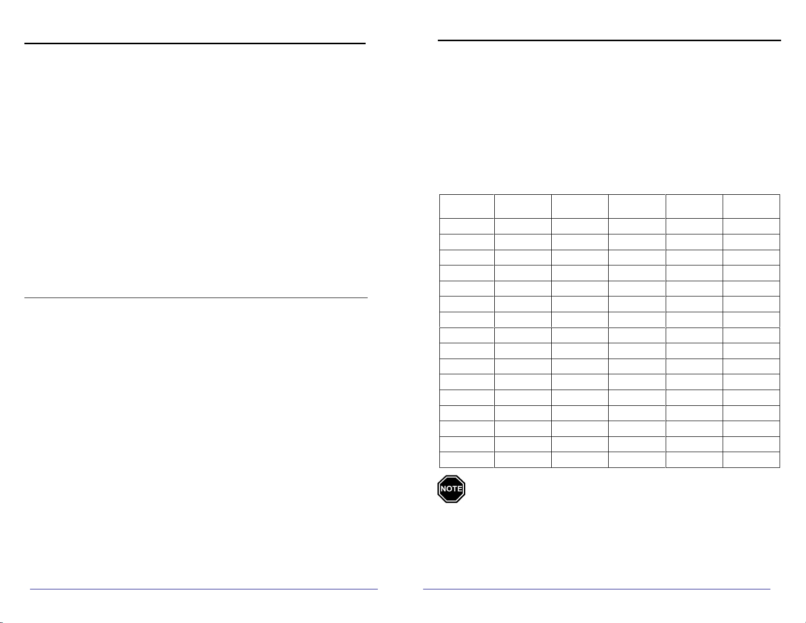
DIP SWITCH 2, 3, 4 and 5: TRANSMIT CHANNEL
The transmitter is capable of transmitting on one of fifteen channels. The
dip switch settings in the Steffes PLC transmitter MUST be set to match
the channel setting of the receiving device(s).
To select the power line carrier communication channel desired, use the
chart below and set dip switches 2, 3, 4 and 5 to the appropriate positions.
If dip switch 2, 3, 4, and 5 are all set to the "OFF" positions, the
transmitter will not transmit a power line carrier signal.
FACTORY DEFAULT = Channel One (2 ON, 3 OFF, 4 OFF, 5 OFF)
CHANNEL
0
1
2
3
4
5
6
7
8
9
10
11
12
13
14
15
DIP
SWITCH #2
OFF OFF OFF OFF N/A
ON OFF OFF OFF SLOW
OFF ON OFF OFF SLOW
ON ON OFF OFF FAST
OFF OFF ON OFF FAST
ON OFF ON OFF FAST
OFF ON ON OFF FAST
ON ON ON OFF FAST
OFF OFF OFF ON FAST
ON OFF OFF ON FAST
OFF ON OFF ON FAST
ON ON OFF ON FAST
OFF OFF ON ON SLOW
ON OFF ON ON SLOW
OFF ON ON ON SLOW
ON ON ON ON SLOW
D
IP
SWITCH #3
D
IP
SWITCH #4
D
IP
SWITCH #5
C
HANNEL
SPEED
1. 1000/2000 Series heaters will ONLY receive on slow speed
channels.
2. If multiple transmitters are installed on the same
distribution transformer, do not use both channels one (1)
and two (2).
4 5
 Loading...