

Page 1
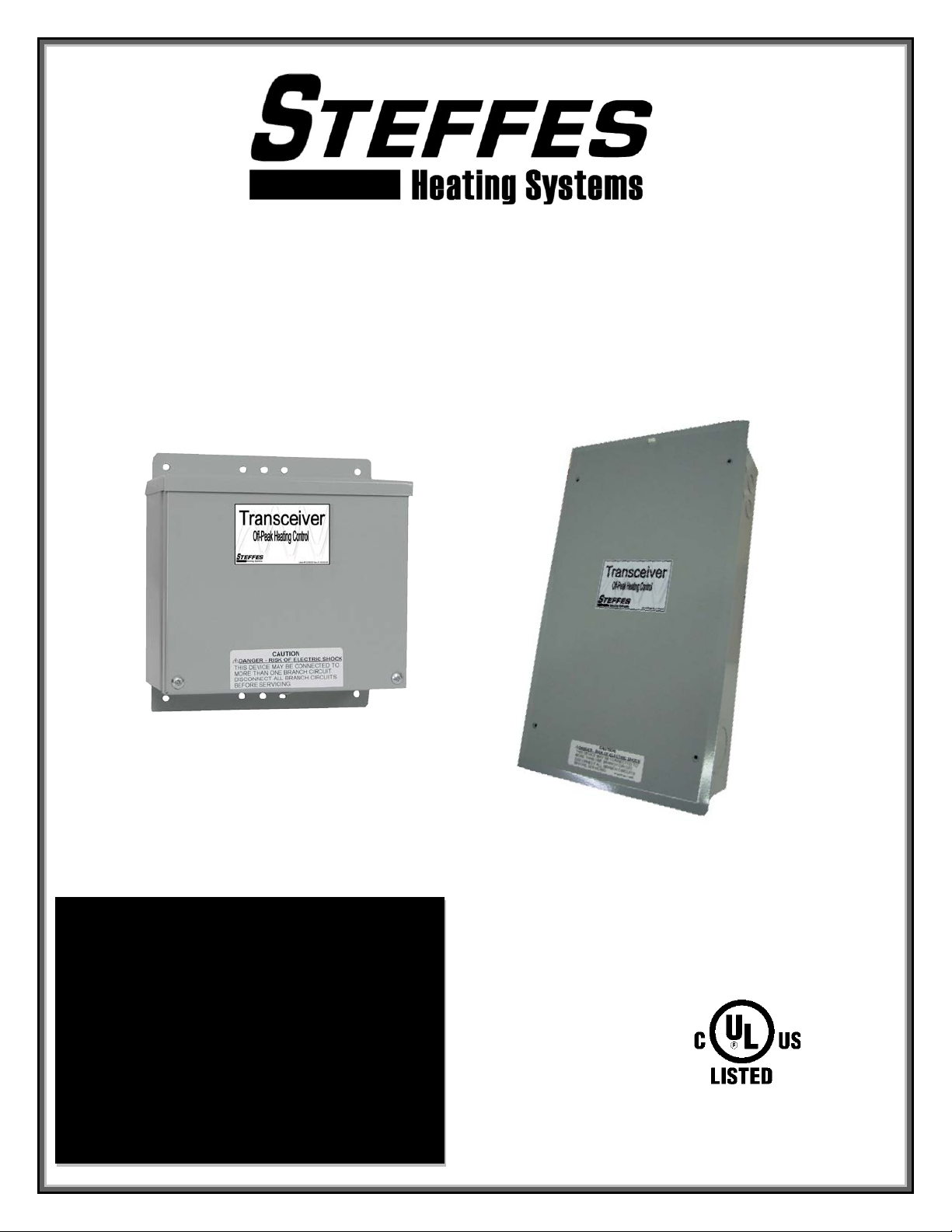
Power Line Carrier (PLC)
Transceiver
Rev 5
2-Pole Transceiver
Configurations Available:
2-pole Indoor
2-pole Outdoor
2-pole 3-phase Outdoor
2-pole with Time Clock Indoor
2-pole with Umbilical Cord Outdoor
5-pole Indoor
5-pole Outdoor
5-pole with CT Indoor
5-Pole Transceiver
"Manufactured in North America"
Page 2
IMPORTANT
The equipment described herein is intended for installation by a qualified technician in accordance
with applicable local, state, and national codes and requirements.
This manual should be retained by the owner upon completion of the installation and made
available to service personnel as required.
Disclaimer:
In compiling this manual, Steffes Corporation has used its best judgment based upon
information available, but disclaims any responsibility or liability for any errors or
miscalculations contained herein, or any revisions hereof, or which result, in whole or in part,
from the use of this manual or any revisions hereof.
Conditions may occur which cause the power line carrier transceiver to have difficulties
communicating; therefore, not operating properly. In no event shall Steffes Corporation be
liable for any indirect, special, or consequential damages or lost profits.
WARNING
HAZARDOUS VOLTAGE: Risk of electric shock. Can cause
injury or death. System may be connected to more than
one branch circuit. Disconnect power to all circuits before
servicing. Equipment must be installed and serviced by a
qualified technician.
Please record the serial number of the transceiver below. This information is located inside the transceiver
enclosure. Retain this information for future reference.
Serial No. _____________________________________ Date Installed ________________________
F
OR CUSTOMER USE
Page 3

TABLE OF CONTENTS
Personal Safety Instructions
Safety Alert Symbols ........................................................................................................................ 1
Signal Words .................................................................................................................................... 1
General Operation .................................................................................................................... 2
Specifications
Electrical .......................................................................................................................................... 2
Mechanical ....................................................................................................................................... 3
Component Location ............................................................................................................4-7
Unit Identification Label .......................................................................................................... 8
Transceiver Installation
Mounting .......................................................................................................................................... 9
Line Voltage Connections .......................................................................................................... 10-11
Transceiver Relay Connections (Optional) ..................................................................................... 12
Transmit/Receive Select Jumper .................................................................................................... 13
Transmit Mode Low Voltage Connections ........................................................................... 13
DIP Switch Settings
Factory Defaults ............................................................................................................................. 14
Transmit Mode DIP Switch Settings .......................................................................................... 14-15
Receive Mode DIP Switch Settings ................................................................................................ 15
Relay Operation ..................................................................................................................... 16
LED Functions ........................................................................................................................ 17
Electronic Override Modules (Optional).......................................................................... 18-19
Check Out Procedures
Transmit Mode Check Out Procedure ...................................................................................... 19-20
Receive Mode Check Out Procedure ............................................................................................. 20
Wiring Diagrams
Low Voltage Wiring Diagram .......................................................................................................... 21
Line Voltage Wiring Diagrams ................................................................................................... 22-24
Warranty ................................................................................................................................. 25
Page 4
PERSONAL SAFETY INSTRUCTIONS
Safety Alert Symbols
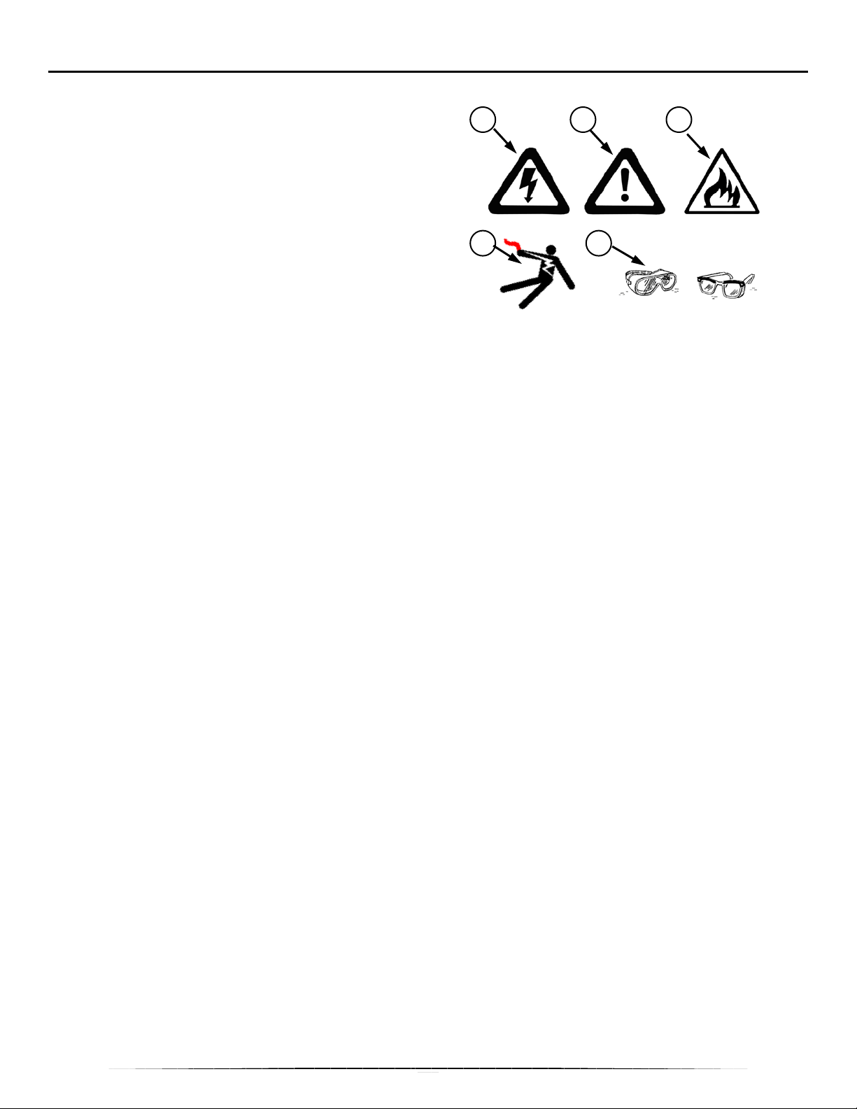
Three safety alert symbols may be used to alert you to
personal safety instructions. They are:
• Electrical (1 & 4)
• Mechanical (2)
• Fire (3)
• Personal Protective Equipment (PPE) (5)
1 2 3
4 5
These safety alert symbols are used to alert you to
hazards. Obey all safety messages that follow these
symbols to avoid possible injury or death.
Signal Words
Signal words that may appear next to the safety alert symbol are:
• DANGER
• WARNING
• CAUTION
• IMPORTANT
• NOTE
Carefully read and understand the instructions before you continue.
DANGER indicates a hazardous situation which, if not avoided, will result in death or
serious injury.
WARNING indicates a hazardous situation which, if not avoided, could result in death
or serious injury.
CAUTION, used with the safety alert symbol, indicates a hazardous situation which, if
not avoided, could result in minor or moderate injury.
IMPORTANT indicates a special instruction or procedure which, if not followed, may
cause damage to the equipment.
NOTE indicates additional information about a subject or procedure for a more efficient
or convenient installation.
1
Page 5
GENERAL OPERATION
General Information
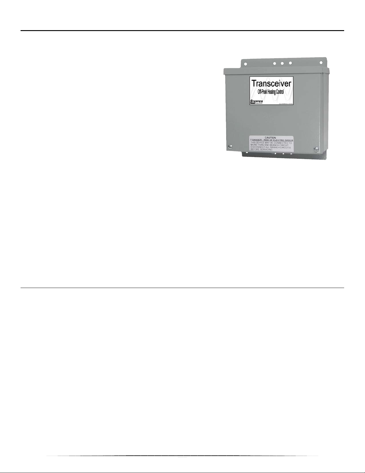
This Steffes Power Line Carrier (PLC) Transceiver is to be
installed in your customer's home or business to provide
communication to and control of Steffes heating systems and/or
other devices. The PLC Transceiver is used for communicating
information through the local electric circuits and must be wired
into the line voltage power serving the installation.
The transceiver can be installed as a transmitter OR a receiver.
In transmit mode, it receives a signal from an external control
device such as a power company’s meter or radio receiver, a time
clock, or other control device. The transmitter interprets the signal
and sends the signal to any Steffes receivers installed on the same
distribution transformer. The transmitter also collects and transmits
outdoor temperature data. Steffes heating systems have a built-in
receiver. There are also relays in the transceiver which can be used to control other loads.
In receive mode, the transceiver reads and translates the signal from the transmitter. It uses the information
received to control other electric load devices by turning power off and on to the device with its relays. Other
controlled-load devices might be an electric water heater, electric baseboard heater, electric clothes dryer, etc.
NOTE: PLC Communication is very reliable in most applications but can be affected and hindered
by connection method used, electrical layout of the application, operation of other
equipment in the same electric system, dirty power, etc. Steffes Corporation does not
guarantee effective communication of the PLC system in all applications and is not
responsible for communication issues.
SPECIFICATIONS
Electrical
Control Circuit:
Line Power (single-phase) .................................................................................. 120 or 240/208 VAC
Current .............................................................................................................0.2 amps
Communication Channels .............................................................................................................. 15
Transmitter Frequency .............................................................................................. 13.3 – 15.2 kHz
Low Voltage Input Switch Loading from R terminal to all other low volt age terminals .............. 1-2 mA
Load-Control Relays:
Line Power (single-phase) .................................................................................. 120 or 240/208 VAC
Maximum Load per Relay ..................................................................................................... 24 amps
Maximum Controlled Motor Load @ 120VAC ............................................................................. 1 HP
Maximum Controlled Motor Load @ 208 or 240 VAC .............................................................. 1.5 HP
NOTE: In single-phase applications, the most effective circuit board operation voltage is 240/208 VAC.
2
Page 6
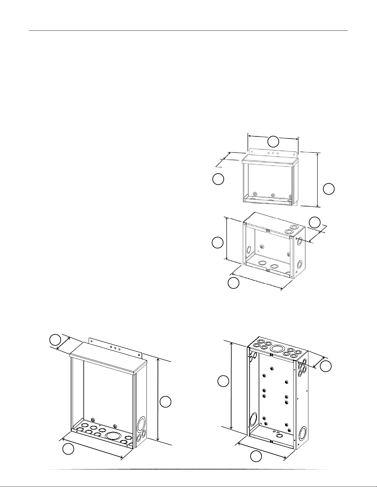
SPECIFICATIONS
1 2 3 1
2
2 3
Mechanical
Enclosures Available:
Outdoor, (A) ................................................................................................................... Surface Mount
Indoor Only, (B) ................................................................................................ Flush or Surface Mount
Features:
Knockout Size ............................................................................................... 1/2 & 3/4" (12.7 & 19 mm)
Number of Knockouts:
Outdoor ......................................................................................................................................... 4
Indoor ............................................................................................................................................ 8
Ground Bond Point .......................................................................................... SecureGround™ Screw
Security ................................................................................................. Power Company Seal/Lockout
2-pole Outdoor Size:
Width, (1) ................................... 8.50” (215.9 mm)
Height, (2) .................................. 9.00” (228.6 mm)
Depth, (3) .....................................3.68” (93.5 mm)
2-pole Indoor Size:
Width, (1) ................................... 8.50” (215.9 mm)
Height, (2) .................................. 7.00” (177.8 mm)
Depth, (3) .....................................3.50” (88.9 mm)
*Available with Optional Time Clock
5-pole Outdoor Size:
Width, (1) .............................. 11.50” (292.1 mm)
Height, (2) ............................. 16.00” (406.4 mm)
Depth, (3) ................................... 4.25” (108 mm)
3
2
5-pole Indoor Size:
Width, (1)........................ 10.00” (254 mm)
Height, (2) ................... 18.00” (457.2 mm)
Depth, (3) ......................... 4.25” (108 mm)
*Available with Optional CT
A
3
B
A
1
3
B
1
Page 7
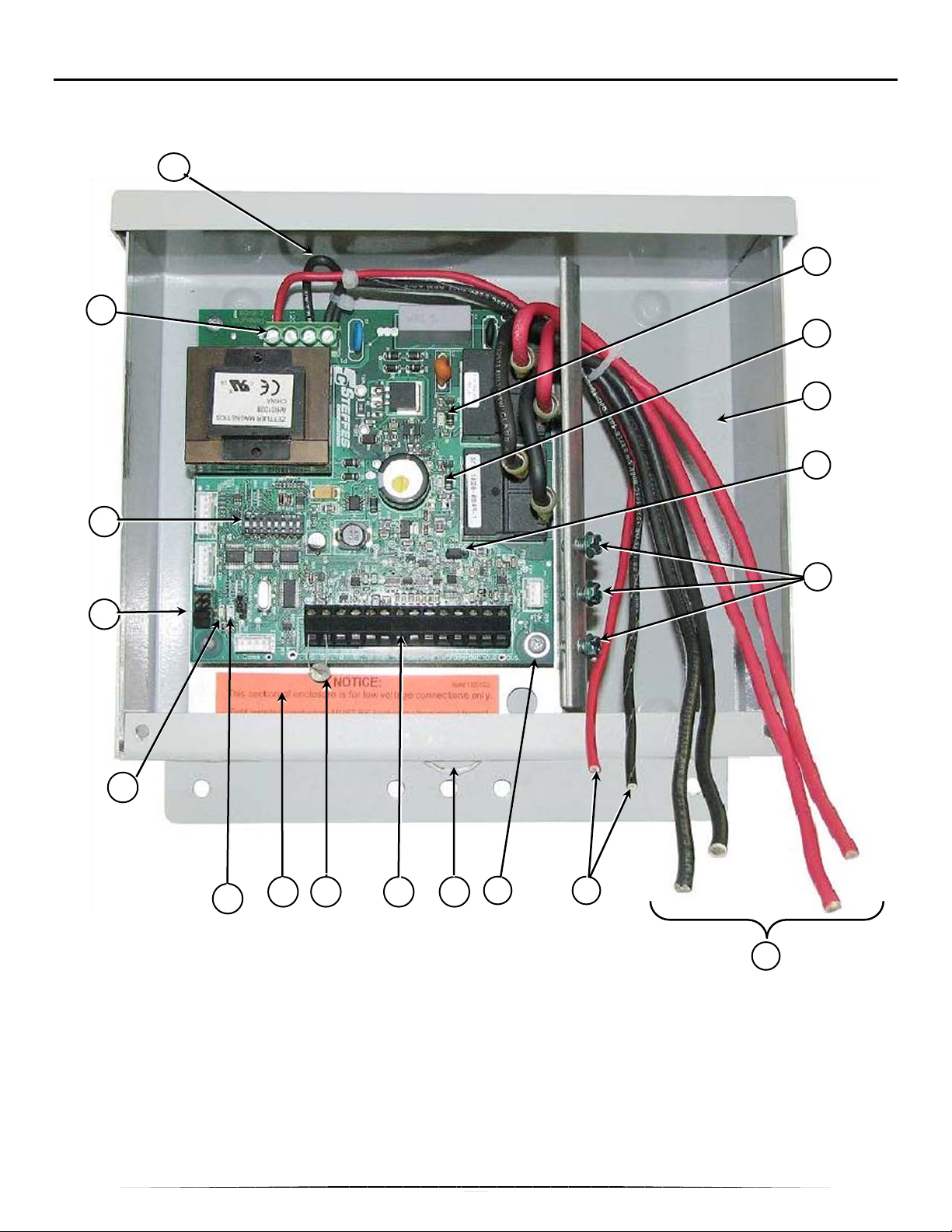
COMPONENT LOCATION 2-POLE INDOOR/OUTDOOR
3
4
6 7 8
9
14 11 12 10
1
Use this illustration to familiarize yourself with the location of parts you will use as the transceiver is installed,
set up, and its operation checked. The 2-pole transceiver shown is an outdoor enclosure; however, all
components are located in relatively the same locations in the indoor enclosure.
17
16
18
15
13
1 - Line Voltage Tapping [Page 10] 10 - Security Lockout/Seal Loop
2 - Relay #1 LED (marked "Relay 1") [Page 17] 11 - Low Voltage Terminal Block [Page 13]
3 - Relay #2 LED (marked "Relay 2") [Page 17] 12 - Temperature Sensing Thermistor [Page 13]
4 - Line Voltage Connection Area [Page 24] 13 - Low Voltage Connection Area [Page 13]
5 - Transmit/Receive Jumper ("TR/RC") [Page 13] 14 - Outside Temperature Indicator LED ("L3") [Page 17]
6 - SecureGround™ Ground Bond Screw [Page 10] 15 - PLC Signal Indicator LED ("L4") [Page 17]
7 - Supply Conductors (from circuit breaker panel) [Page 9] 16 - DIP Switches [Page 14-15]
8 - PCB Line Voltage Conductor “Control Circuit” [Page 9] 17 - Line Voltage Terminal Block [Page 9]
9 - Low Voltage Ground Screw 18 - THER Jumpers – Must be ON for all Transceivers
2
5
4
Page 8
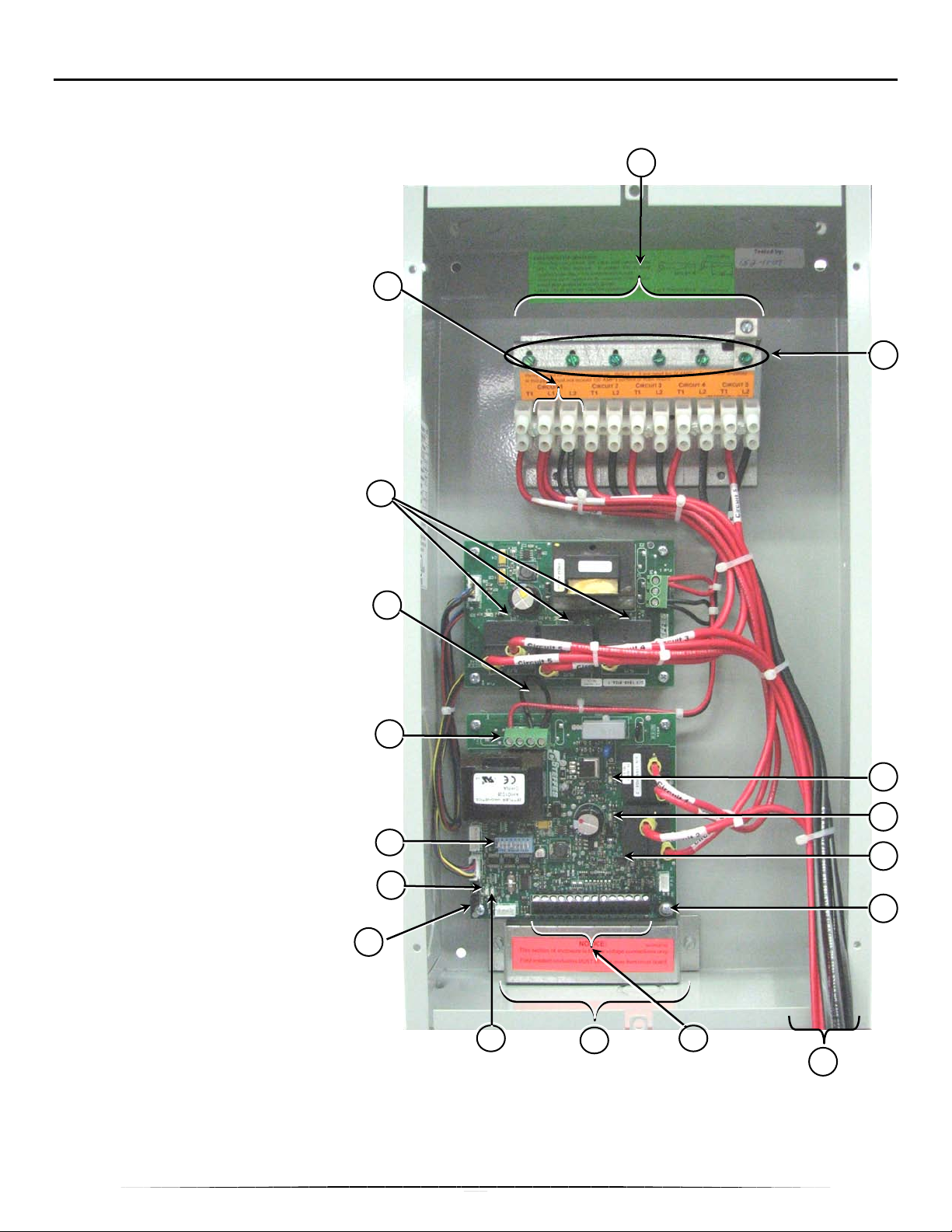
COMPONENT LOCATION 5-POLE INDOOR
1
Line Voltage Select Jumper
2
Relay #1 LED (marked "Relay 1")
3
Relay #2 LED (marked "Relay 2")
4
Load Connection Area [Page 11]
LED’s for expansion board
2
15
4
5
14
19
Use this illustration to familiarize yourself with the location of parts you will use as the transceiver is installed,
set up, and its operation checked.
[Page 11]
[Page 17]
[Page 17]
5 Transmit/Receive Jumper
("TR/RC") [Page 13]
6 SecureGround™ Ground Bond
Screw [Page 11]
7 Controlled Load Line Voltage
Conductors [Page 12]
8 PCB Line Voltage Conductor
“Control Circuit” [Page 11]
9 Low Voltage Ground Screw
10 Security Lockout/Seal Loop (N/A
on Indoor Enclosure)
11 Low Voltage Terminal Block
[Page 13]
12 Temperature Sensing
Thermistor (N/A on Indoor
Enclosure. Install outdoor
sensor if desired.) [Page 13]
13 Low Voltage Connection Area
[Page 13]
14 Outside Temperature Indicator
LED ("L3") [Page 17]
15 PLC Signal Indicator LED ("L4")
[Page 17]
16 DIP Switches [Page 14-15]
17 PCB Line Voltage Terminal
Block [Page 11]
Relay
18
relays [Page 17]
8
18
1
17
16
6
3
9
19 THER Jumpers – Must be ON for
all Transceivers
5
13
11
7
Page 9
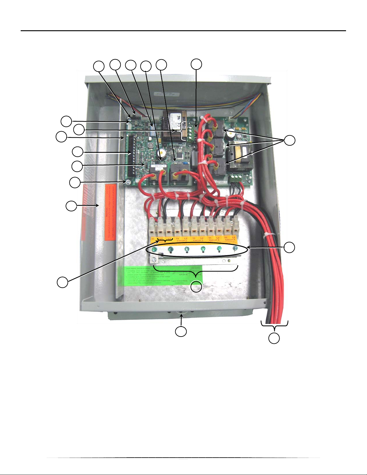
COMPONENT LOCATION 5-POLE OUTDOOR
1 2
3 15 8
5 7
9
4
14
10
Use this illustration to familiarize yourself with the location of parts you will use as the transceiver is installed,
set up, and its operation checked.
17
12
11
13
19
16
18
6
1 - Line Voltage Select Jumper [Page 11] 10 - Security Lockout/Seal Loop
2 - Relay #1 LED (marked "Relay 1") [Page 17] 11 - Low Voltage Terminal Block [Page 13]
3 - Relay #2 LED (marked "Relay 2") [Page 17] 12 - Temperature Sensing Thermistor [Page 13]
4 - Load Connection Area [Page 11] 13 - Low Voltage Connection Area [Page 13]
5 - Transmit/Receive Jumper ("TR/RC") [Page 13] 14 - Outside Temperature Indicator LED ("L3") [Page 17]
6 - SecureGround™ Ground Bond Screw [Page 11] 15 - PLC Signal Indicator LED ("L4") [Page 17]
7 - Controlled Load Line Voltage Conductors [Page 12] 16 - DIP Switches [Page 14-15]
8 - PCB Line Voltage Conductor “Control Circuit” [Page 11] 17 - PCB Line Voltage Terminal Block [Page 11]
9 - Low Voltage Ground Screw 18 - Relay LED’s for expansion board relays [Page 17]
19 - THER Jumpers – Must be ON for all Transceivers
6
Page 10
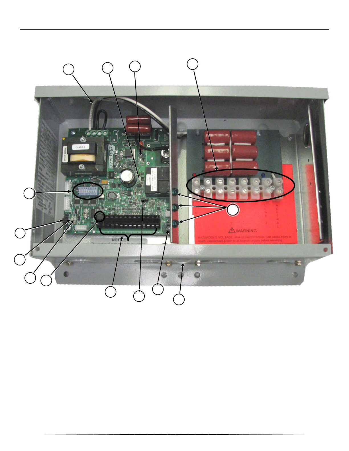
COMPONENT LOCATION 3-PHASE
14
12
9
6
5
Use this illustration to familiarize yourself with the location of parts you will use as the transceiver is installed,
set up, and its operation checked.
1
3
2
13
11
10
8
1 - Line Voltage Select Jumper [Page 10] 8 - Low Voltage Terminal Block [Page 13]
2 - Relay #1 LED (marked "Relay 1") [Page 17] 9 - Temperature Sensing Thermistor [Page 13]
3 - Relay #2 LED (marked "Relay 2") [Page 17] 10 - Outside Temperature Indicator LED ("L3") [Page 17]
4 - Transmit/Receive Jumper ("TR/RC") [Page 13] 11 - PLC Signal Indicator LED ("L4") [Page 17]
5 - SecureGround™ Ground Bond Screw [Page 10] 12 - DIP Switches [Page 14-15]
6 - Low Voltage Ground Screw 13 - PCB Line Voltage Terminal Block [Page 10]
7 - Security Lockout/Seal Loop 14 - THER Jumpers – Must be ON for all Transceivers
4
7
7
Page 11
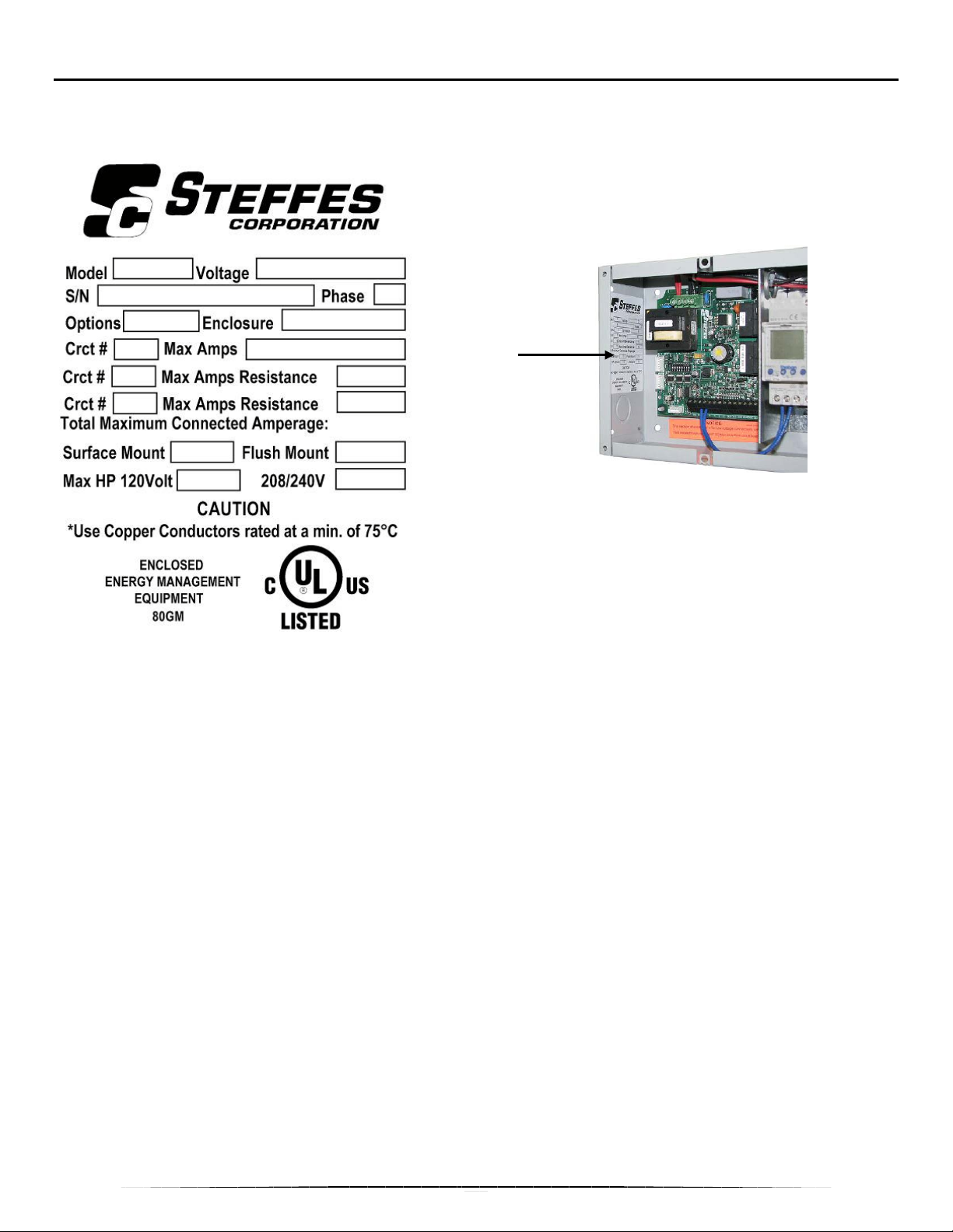
UNIT IDENTIFICATION LABEL
The unit identification label shown is a sample. The actual unit identification label is located inside the
transceiver and contains the following information:
1 Model Number (TR + Number of Relays)
2 Operation Voltage(s)
• “208/240”
• “120”
3 Serial Number
4 Electrical Phase
• 1
• 3
5 Options (Includes Software Version)
• T = Time Clock
• C = Current Transformer
• W = Pre-Wired
6 Enclosure Type
• I = Indoor
• R = Rainproof
1
3
5
7
9
9
11
13
2
4
6
8
10
10
12
14
Unit
Identification
Label
7 Circuit # for Circuit Board
8 Maximum Amperage fo r C ircuit Board:
• Power Input = 0.2
• Time Clock = N/A
9 Relay Circuit Num be r
10 Maximum Amperage Load for Relay
11 Maximum Connected Amperage for Surface
Mount Installation
12 Maximum Connected Amperage for Flush Mount
Installation (Indoor Enclosure Only)
13 Maximum Controlled Electric Motor Load when
powered with 120 VAC
14 Maximum Controlled Electric Motor Load when
powered with 208/240 VAC
8
Page 12
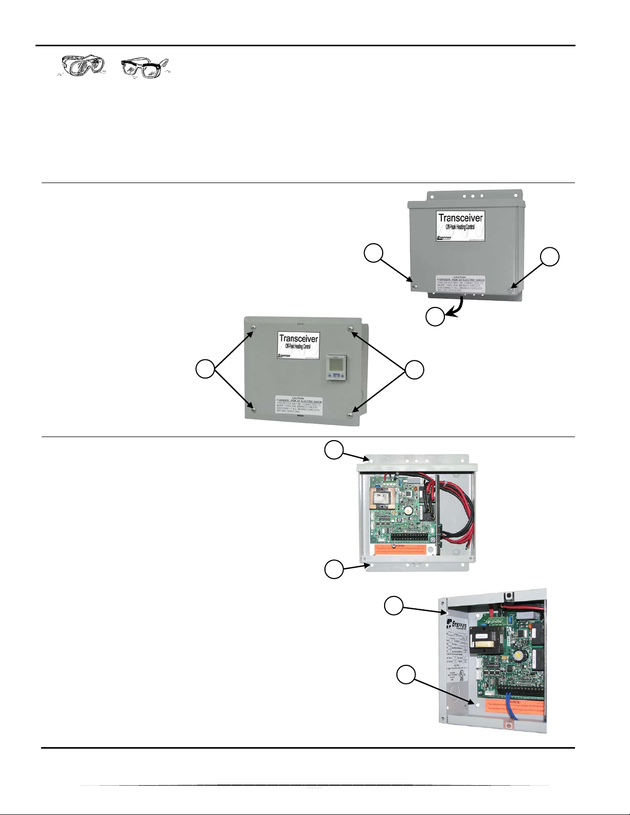
TRANSCEIVER INSTALLATION
1
1 1 1 2 1 1 1 2
CAUTION: Risk of eye i njury due to flying debris. Wear eye
protection at all times during this installation.
IMPORTANT: Maximum Transceivers per Utility or Distribution Transformer – The
transceiver can be installed as a transmitter OR a receiver. Install no more
than four transmitters on one distribution transformer. There is no limit to
the number of receivers in a system.
Remove Enclosure Cover
Rainproof Enclosure
1. Remove two screws, (1).
2. Move bottom of cover down 1/2" (12 mm) and
toward you, (2), to remove cover.
Indoor Enclosure
1. Remove four screws, (1).
Mount Transceiver
Rainproof Enclosure
Securely mount the transceiver for your application.
NOTE: 10 – 1/4" (6.5 mm) holes, (1), are
provided to attach the rainproof
enclosure to the mounting surface.
Indoor Enclosure
NOTE: 4 – 3/16 x 3/8" (4.8 x 9.5 mm) slots, (1),
are provided to install indoor enclosure
flush mounted.
4 – 1/4" (6.5 mm) holes, (2), are
provided to install indoor enclosure
surface mounted.
9
Page 13
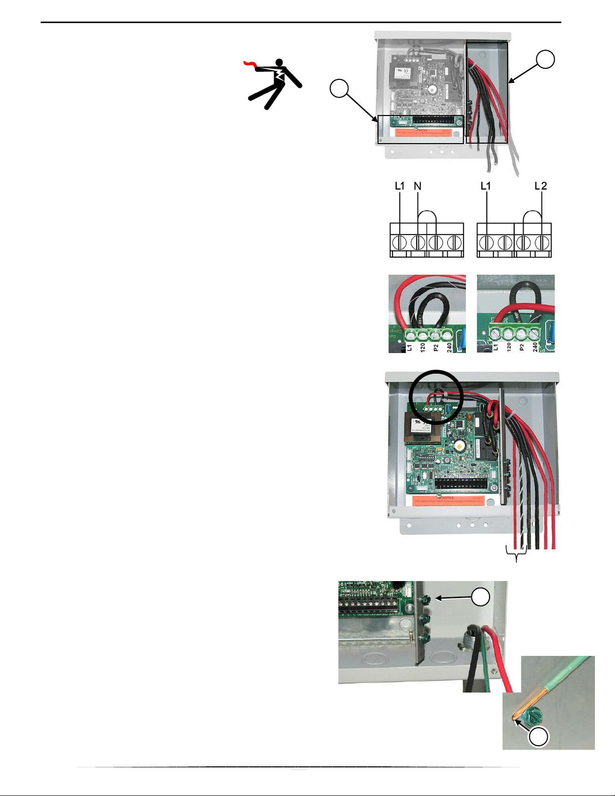
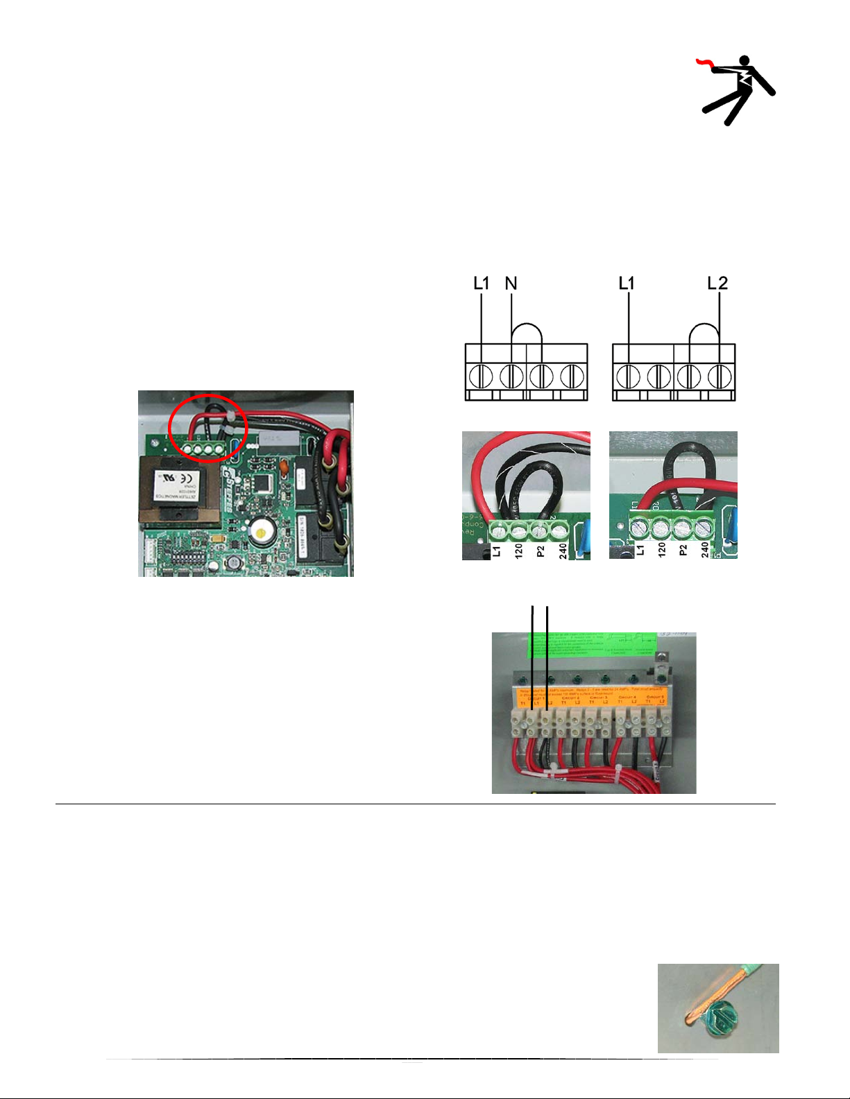
Line Voltage Connections 2-Pole
connect to the two 16 AWG wires coming from the
2 1
WARNING:
Hazardous Voltage. Can cause
injury or death.
Route line-voltage conductors
(circuit board power and
controlled-load circuits) and make linevoltage connections only in the line-voltage
connection area, (1).
Use only copper conductors that are rated
for 75° C minimum.
Route low-voltage conductors (remote
outdoor sensor, power company
signal/control switch, override switch, etc.)
only into the low-voltage connection area,
(2).
Install in accordance with applicable local,
state, and national codes and regulations.
120VAC
240VAC
1. The transceiver can be powered with 120 VAC or
208/240 VAC. Before connecting power to the
transceiver, the circuit board MUST be tapped for
the appropriate input voltage as shown.
NOTE: 208VAC/240VAC is factory default.
2. Route line voltage wiring to the transceiver and
circuit board.
NOTE: For 120VAC power, connect the neutral
wire to L1 and connect the hot wire to
L2.
SecureGround™ Ground Bond
NOTE: This transceiver has SecureGround™
ground wire bond points. Use this
procedure to connect line-voltage
ground wires to the enclosure
throughout this installation instruction.
1. If used, connect ground wire to SecureGround™
screw by inserting the end of the wire into
SecureGround™ anchor hole, (2).
1
NOTE: This connection accepts 14 to 10 AWG
solid conductor only.
2. Hold wire firmly and bend it clockwise, 350º
around screw shank as shown.
IMPORTANT: Make sure no insulation is
between wire and screw head.
3. Tight en screw securely.
2
10
Page 14
Line Voltage Connections 5-POLE
WARNING:
Hazardous Voltage. Can cause injury or death.
Route line-voltage conductors (circuit board power and controlled-load circuits)
and make line-voltage connections only in the line-voltage connection area.
Use only copper conductors that are rated for 75° C minimum.
Route low-voltage conductors (remote outdoor sensor, power company signal/control switch,
override switch, etc.) only into the low-voltage connection area.
Install in accordance with applicable local, state, and national codes and regulations.
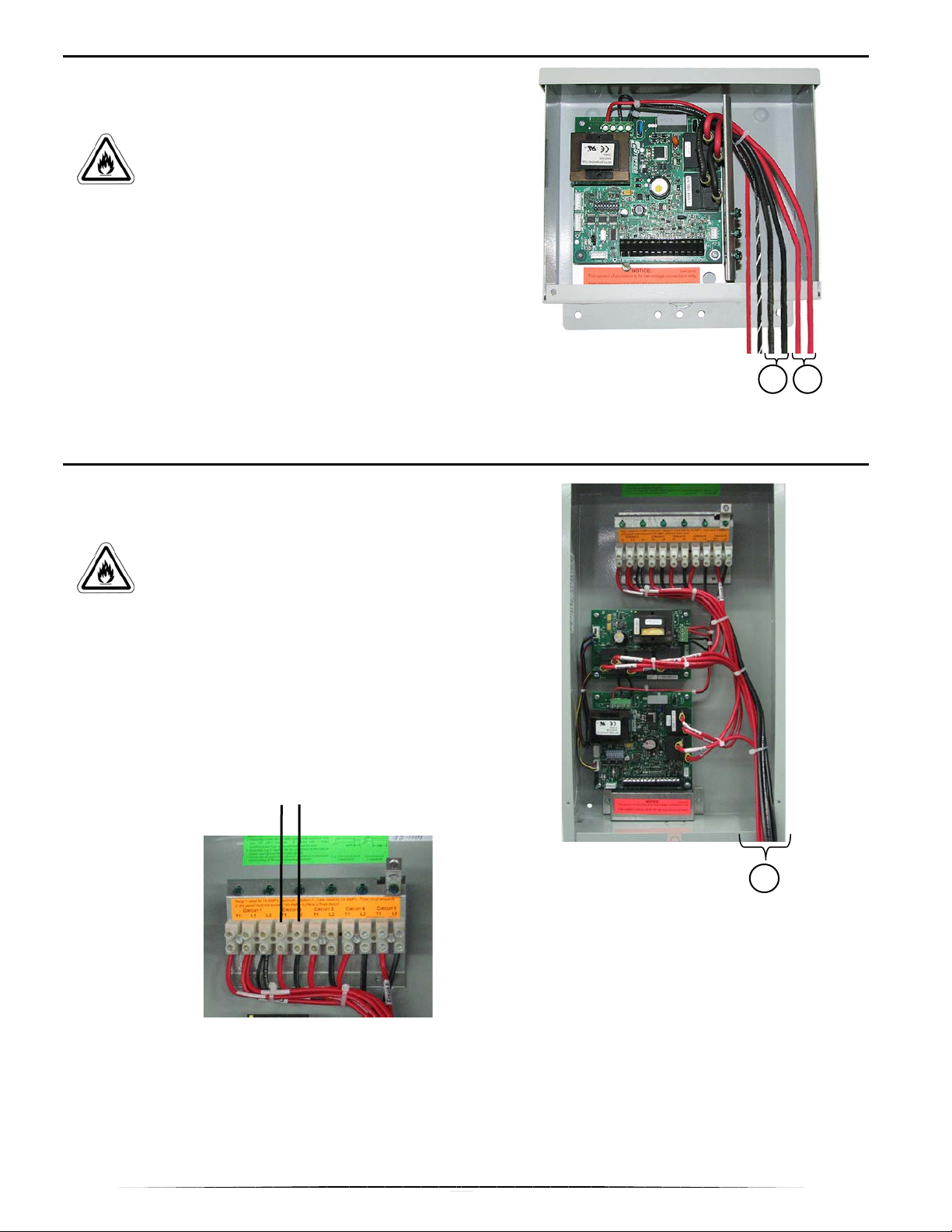
1. The transceiver can be powered with 120 VAC or
208/240 VAC. Before connecting power to the
transceiver, the circuit board MUST be tapped for
the appropriate input voltage as shown.
NOTE: 208VAC/240VAC is factory default.
Route line voltage wiring to the transceiver and
2.
connect to L1 and L2 terminals on Circuit #1 as
shown to the right.
120VAC
L1 L2
240VAC
SecureGround™ Ground Bond
NOTE: This transceiver has SecureGround™ ground wire bond points. Use this procedure to
connect line-voltage ground wires to the enclosure throughout this installation instruction.
1. If used, connect ground wire to SecureGround™ screw by removing 1±1/8" (25.4±3 mm) insulation from
ground wire.
NOTE: Anchor hole accepts 14 to 10 AWG solid conductor.
2. Insert end of wire into SecureGround™ anchor hole. Hold wire firmly and bend it clockwise, 350º around
screw shank.
IMPORTANT: Make sure no insulation is between wire and screw head.
3. Tighten screw securely.
11
Page 15
to control
them to the service entrance panel. Connect these
1
installed are not allowed to have
relays. Doing so is a violation of
Transceiver Relay Connections 2-Pole
(Optional)
CAUTION: Risk of fire. Can cause
personal injury or death. Use only copper
conductors that are rated at 75° C.`
minimum.
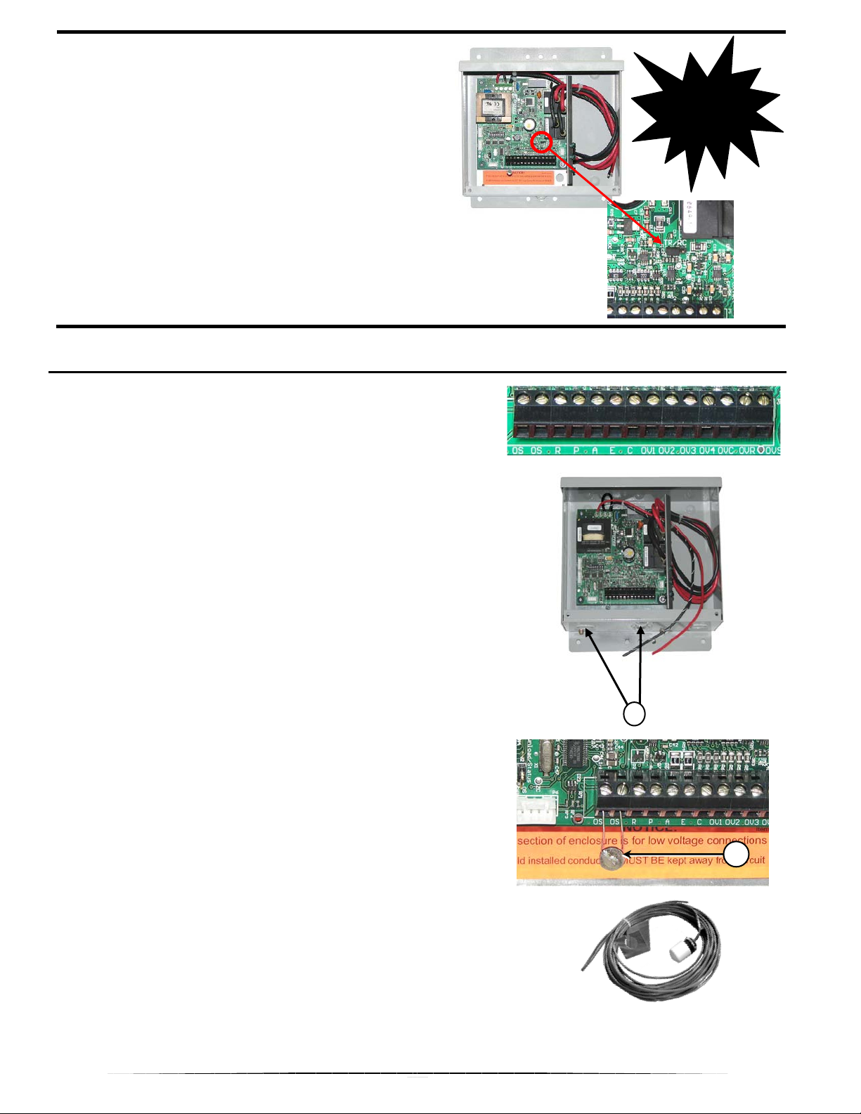
1. If any transceiver relay(s) are NOT being used
to control other loads, insulate the ends of the
unused wires.
2. If the transceiver relay(s) are being used
other loads, one leg of the circuit going to the
controlled load will be broken through the relay.
3. To use controlled-load Relay #1, use the red relay
wires, (1). To use controlled-load Relay #2, use
the black relay wires, (2).
Transceivers with time clocks
external loads connected to the
2
NOTE: Refer to the Relay Operation section of
the manual for more information.
Transceiver Relay Connections 5-Pole
(Optional)
CAUTION: Risk of fire. Can cause
personal injury or death. Use only copper
conductors that are rated at 75° C.`
minimum.
1. Controlled loads will be connected to the T1 and
L2 terminals for the desired Circuit # as shown
below.
2. Locate the red and black wires at the bottom of
the transceiver, (1), for that Circuit # and route
wires to an appropriate circuit breaker in the
panel.
T1 L2
the Transceiver’s UL Listing.
1
NOTE: Refer to the Relay Operation
section of the manual for more
information.
12
Page 16
Transmit/Receive Select Jumper
2
1
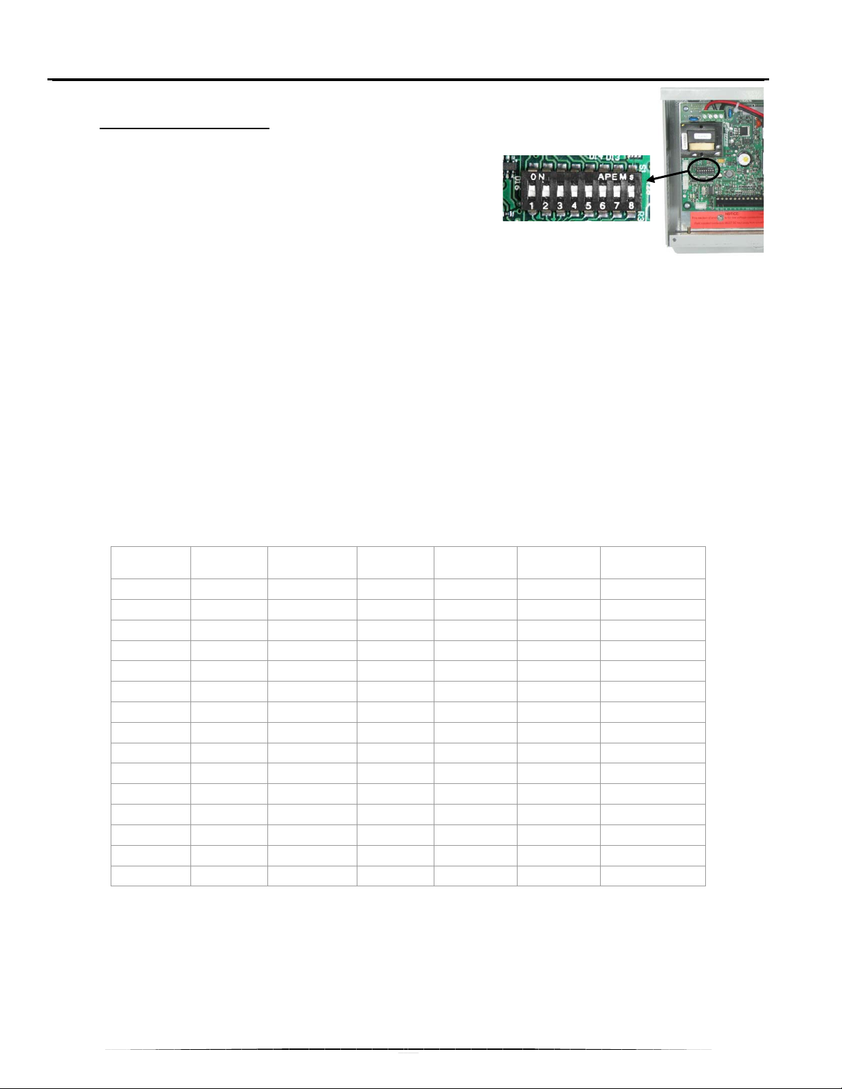
1. The transceiver can be used as a transmitter OR
a receiver, dependent upon how the TR/RC
jumper is positioned.
2. To use as a transmitter, place the select jumper is
on the “TR” position as shown (jumper covers the
left and center pins).
3. To use as a receiver, place the select jumper to
the “RC” position (jumper covers the center and
right pins).
TRANSMIT MODE LOW VOLTAGE CONNECTIONS
Low Voltage Terminal Strip
OS Outdoor Sensor
OS Outdoor Sensor
R Low Voltage Hot
P Peak Control
A Ant icipated Peak Control
E Room Temperature Setback
C Common
OV1 Override 1
OV2 Override 2
OV3 Override 4
OVC O verride Common
OVR O verride Hot
OVS Override Switch
JUMPER
POSITION
AFFECTS
OPERATION
NOTE: Each terminal accepts 22-16 AWG wire.
1. Remove applicable knockout(s), (1), from bottom of
enclosure in low-voltage connection area.
2. Connect the peak control wires to R and P.
NOTE: Outdoor transceivers have a factory-installed
outdoor temperature sensor (thermistor), (2). If the
transmitter is being installed in an area where an
accurate outdoor temperature is not available, the
thermister should be removed and an outdoor
temperature sensor (Order Item #1302044) should
be installed.
3. If installing an outdoor temperature sensor, connect the
outdoor temperature sensor to the two OS terminals. The
outdoor sensor must be placed in a location where it can
accurately sense outdoor temperature and is not affected by
direct sunlight or other abnormal temperature conditions.
NOTE: If necessary, the outdoor sensor can be extended
to a total of 250 ft. No other loads can be
controlled or supplied through this cable. It is for
connection of the outdoor sensor ONLY.
13
Page 17
DIP
DIP Switch
DIP
DIP
Channel
Transmit
DIP SWITCH SETTINGS
Factory Defaults
DIP Switch # Setting
1 ON
2 ON
3 ON
4 OFF
5 OFF
6 OFF
7 OFF
8 OFF
TRANSMIT MODE DIP SWITCH SETTING S
DIP Switch #1 – Invert Peak
The transceiver receives a signal, (i.e. switch closure), related to on-peak or off-peak from the power
company or other signaling device. The signal may be a switch “open-to-charge” or “close-to-charge”
signal. The transceiver must be set to match the signaling device. If unsure whether or not the signaling
device opens or closes for charging, contact the power company.
ON = Close to Charge (Off-peak), Open for Control (Peak)
OFF = Open for Charge (Off-peak), Close for Control (Peak)
DIP Switches #2, 3, 4, 5 – Channel Selection
DIP switches 2, 3, 4, and 5 are used to select the channel on which the transceiver will transmit (send
signal). There are 15 channels available. Only one transceiver is required per distribution transformer. If
multiple transceivers in the transmit mode are installed on a single distribution transformer, they must
be set to different channels. Select a channel and set DIP switches 2-5 according to the chart below:
Channel
1
2
3 On On Off Off Fast Constant
4
5
6
7
8
9
10
11
12
13
14
15
Switch 2
On Off Off Off Slow Constant
Off On Off Off Slow Intermittent
Off Off On Off Fast Constant
On Off On Off Fast Constant
Off On On Off Fast Intermittent
On On On Off Fast Constant
Off Off Off On Fast Intermittent
On Off Off On Fast Constant
Off On Off On Fast Constant
On On Off On Fast Constant
Off Off On On Slow Constant
On Off On On Slow Constant
Off On On On Slow Constant
On On On On Slow Constant
3
Switch 4
Switch 5
Speed*
Option**
* Steffes 1000 and 2000 Series room heating units receive only on “slow” speed channels (Channels 1 or 2 as set
from the factory or on channe ls 12/13 or 14/15 with a software upgrade). Slow chan nel s transm it a signal every 34 minutes, so can take up to 7-10 minutes for a receiver to receive. Fast channels transmit every minute, so it
generally only takes 2-3 minutes to receive.
** The Steffes transceiver transmits a signal over the power lines constantly unless set to one of the intermittent
transmit channels shown above. If the power company’s control device is power line carrier (PLC) such as those
manufactured by Cooper Power System/Cannon Technologies, the transceiver must transmit intermittently to
allow the power company’s control device to operate properly. When set to tra nsmit inter m i ttently, the Steffes
Heating systems will display a lower -than-normal percentage of good packets received.
14
Page 18

DIP Switch #6 – Service Override & Automatic Shoulder Charge
DIP switch #6 has two functions. The first function is to provide a short term peak override for checkout
and service of the system. If the transceiver is powered up and DIP switch #6 is moved from the “off”
position to the “on” position and back to “off” again, a 3 hour override will be enabled. This short term
override is to be used when installing or servicing the system.
The second function of DIP switch #6 is to allow for an automatic shoulder charge period for devices
controlled by the relays on the transceiver. When in the “on” position, the transceiver has a built in timer
that starts timing when it receives a peak signal from the power company’s control device. It times for 5
hours and then allows a shoulder charge period (anticipated peak) for 4 hours. After four hours of
shoulder charge, the peak period is resumed until a charge signal is received from the control device.
More information regarding this feature is available in the Relay Operation section of this manual.
DIP Switch #7 – Negative Outdoor Temperature Calibration
DIP switch #7 is used to adjust the outdoor temperature reading being transmitted to the Steffes
receivers by 5° F (2.78° C) lower than the actual outdoor temperature. This DIP switch is only used if
the heating system is reading an outdoor temperature higher than the actual outdoor temperature.
DIP Switch #8 – Positive Outdoor Temperature Calibration
DIP switch #8 is used to adjust the outdoor temperature reading being transmitted to the Steffes
receivers by 5° F (2.78° C) higher than the actual outdoor temperature. This DIP switch is only used if
the heating system is reading an outdoor temperature lower than the actual outdoor temperature.
RECEIVE MODE DIP SWITCH SETTINGS
DIP Switch #1 – Anticipated Peak (Pre-Peak) Operation Mode
This DIP switch determines how an anticipated peak (pre-peak) signal will affect the relays. For power
companies desiring to control loads separately using separate signals, this DIP switch can be used to
do peak control of devices on a separate rate strategy. Generally, anticipated-peak signals are not used
and this DIP switch should be placed in the "OFF" position.
ON = Relays will be activated by an anticipated peak (pre-peak) signal.
OFF = Relays will NOT respond to an anticipated peak (pre-peak) signal.
DIP Switches #2, 3, 4, 5 – Channel Selection
DIP switches 2, 3, 4, and 5 are used to select the channel on which the receiver will receive. The
receiver and the transmitting device MUST be set to the same channel for proper communication to
occur. To select the desired channel, use the chart on page 14 and set DIP switches 2, 3, 4, and 5
accordingly.
DIP Switch #6 – Automatic Shoulder Charge (Specialty Applications Only)
DIP switch #6 is to allow for an automatic shoulder charge period for devices controlled by the relays on
the transceiver. When in the “on” position, the transceiver has a built in timer that starts timing when it
receives a peak signal from the power company’s control device. It times for 5 hours and then allows a
shoulder charge period (anticipated peak) for 4 hours. After four hours of shoulder charge, the peak
period is resumed until an off-peak or anticipated peak signal is received from the control device.
To enable the shoulder charge timers, turn DIP switch #6 to the ON position.
ON = Shoulder Charge Enabled
OFF = Shoulder Charge Disabled
DIP Switch #7 – Default Relay Status
DIP switch #7 determines how the relays will respond when the power line carrier control system is first
energized or if the receiver loses signal from the transmitting device.
ON = The relays will close until a signal is received from the transmitting device.
OFF = The relays will open until a signal is received from the transmitting device.
DIP Switch #8 – Currently Not Utilized
15
Page 19
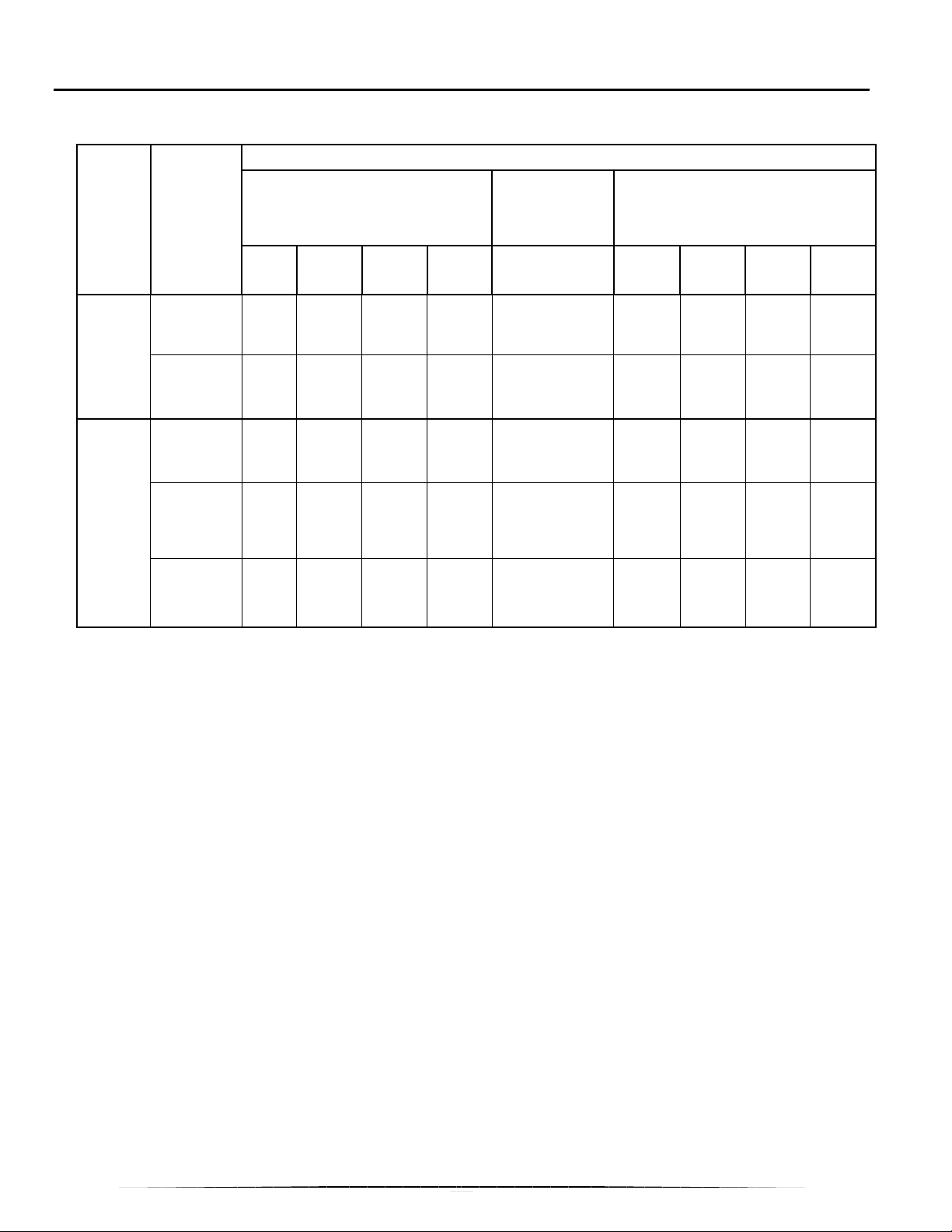
RELAY OPERATION
(Applicable to Controls with Factory Default Settings)
Transceiver Relay Operation
Response to Input Signal
Circuit
Board
Main Board
Expansion Board #1
Relay
Relay 1
Relay 2
Relay 1
Relay 2
Relay 3
Low Voltage Inputs
P A C E
Open Closed Closed Closed Closed Closed Open Open Open
Open Closed Closed Closed Open Open Closed Open Open
Open Closed Closed Closed Closed Open Open Closed Open
Open Closed Closed Closed Open Open Open Open Closed
Open Closed Closed Closed Closed Closed Open Open Open
DIP Switch
#6 Input
(ON position)
Shoulder
Charge
Override Module Inputs
OV1 OV2 OV3 OV4
16
Page 20
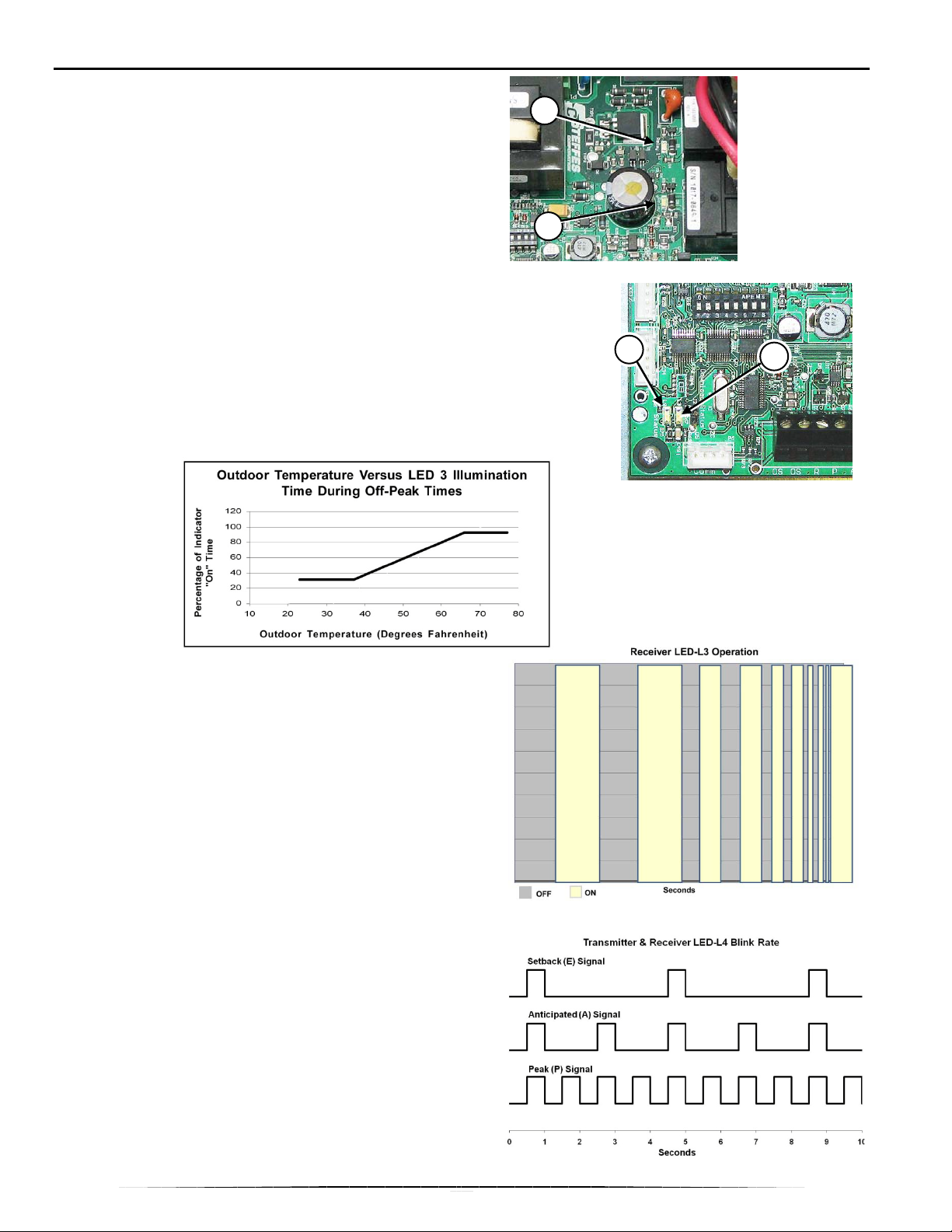
LED FUNCTIONS
reception when using a “fast” channel and
1
2
LED 1 and 2
The relays on the transceiver have LED’s. On the 2pole transceiver, these are marked Relay 1, (1), and
Relay 2, (2). When the corresponding LED is on, the
relay is energized and should be closed. When the
corresponding LED is off, the relay is not energized
and should be open.
LED 3
When s et up as a transmitter, LED 3, (3), blink s OFF
and ON in 4 second intervals with a percentage of ON
time as based on the outdoor temperature. The graph
below illustrates the percent of time the LED is ON at
various temperatures.
The warmer the outside temperature, the longer the
LED stays ON. At 65° F or warmer, the LED is ON
solid.
4
3
When the operation mode is receiver, LED 3 indicates
when the PLC signal reception is established from the
transmitting device. It blinks OFF-and-ON slowly then
increasingly faster until it is ON solid. ON solid
indicates that PLC reception is “locked in”.
NOTE: It can take 2-3 minutes for PLC signal
7-10 minutes when using a “slow”
channel.
LED 4
LED 4, (4), responds to the power company’s control
signal.
• OFF when receiving an off-peak signal
• ON solid if an override switch is enabled
• blinking OFF and ON according to the type of
signal being received from the control device.
This graph illustrates the time, in seconds, the LED is
OFF-and-ON during various types of signal periods.
NOTE: Power company peak signal overrides
anticipated-peak and/or setback signals.
17
Page 21
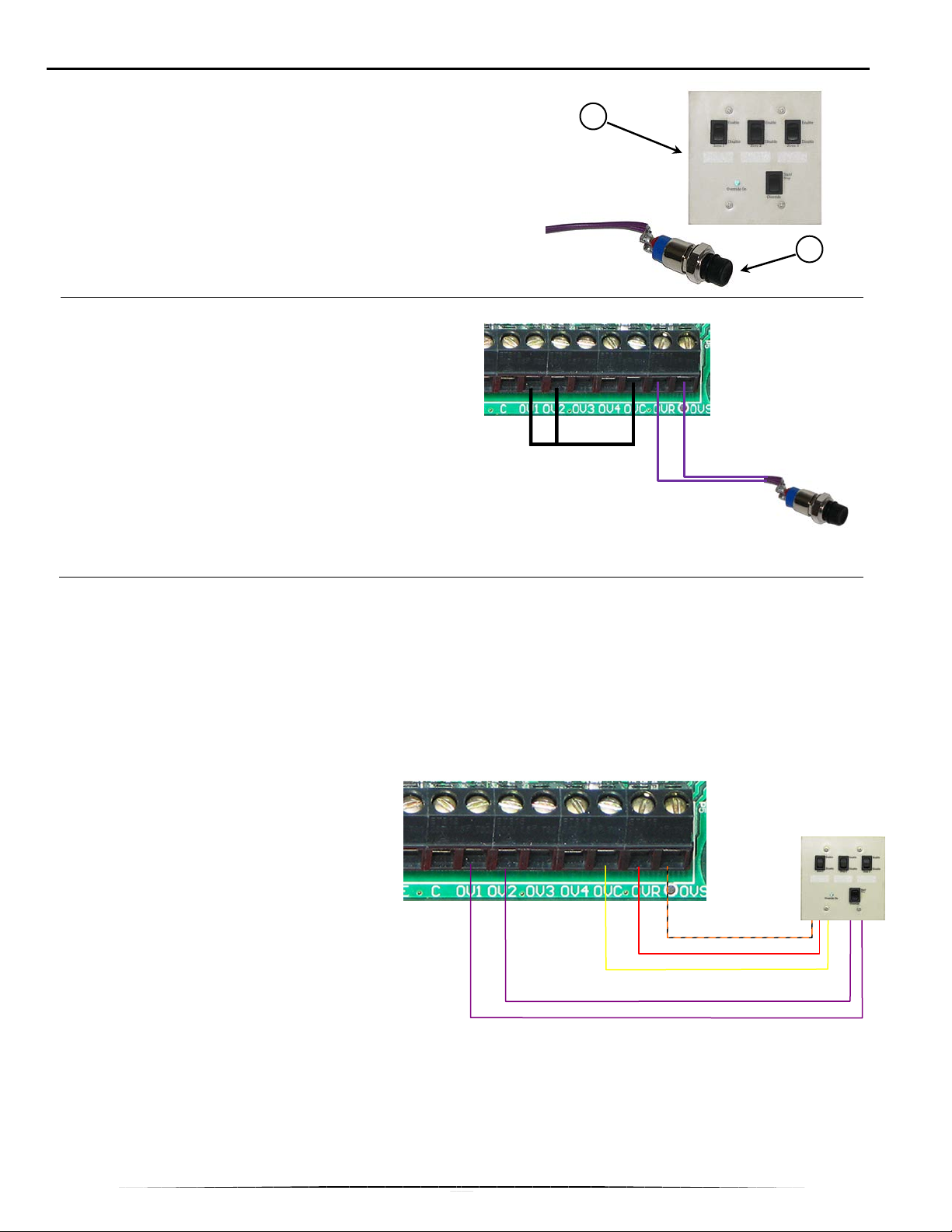
ELECTRONIC OVERRIDE MODULES (OPTIONAL)
1
The Steffes Override Modules are optional devices that allow
the use of a normally controlled device, such as a water heater,
during a peak control time (power company permitting). Either
override timer will allow for an override of the relays. The
override duration is 90 minutes (1.5 hours). It can be cancelled
anytime during the cycle.
There are two electronic override controls available to use with
the transceiver. The push-button override switch, (1), and the
three zone override module, (2).
PUSH-BUTTON OVERRIDE SWITCH
1. When using the push-button override switch,
connect the two purple override wires to the OVR
and OVS terminals on the transceiver board’s low
voltage terminal block.
2. Connect a jumper wire from OVC to OV1 to
override relay #1 and/or from OVC to OV2 to
override relay #2.
NOTE: Refer to the Relay Operation section for
more information on which relays will
utilize the various override inputs.
2
3-ZONE OVERRIDE MODULE
1. Mount the module into a 2-gang box anywhere in the structure where it will be convenient for the user
to access.
2. If using the 3-zone override module, remove applicable transceiver knocko u t(s) from the bottom of the
enclosure below the low-voltage connection area.
3. Connect wires to low-voltage terminal circuit connection points to match circuit leads marked on
override module circuit board (OVS to OVS, OVR to OVR, etc.). Tighten terminal screws securely.
4. The module contains five (5) low
voltage wires: 3 purple, 1 yellow, 1 red,
and 1 orange/black. Splice 18/6 low
voltage wire to these wires and route
them through the low voltage raceway
compartment in the transceiver.
5. Using only line voltage rated wire inside
the transceiver, connect the override to
the low voltage terminal strip in the
transceiver as follows:
Purple wires connect to OV1, OV2,
OV3, or OV4 terminals
Red wire connects to OVR terminal
Orange/black wire connects to OVS terminal
Yellow wire connects to OVC terminal
6. Label each override zone on the module and in the relay panel (inside, on the front cover label).
7. Install the front cover on the transceiver and energize the system.
18
Page 22
Operating the 3-Zone Override Module
P
1. The module is marked with three separate zones: Zone 1, Zone 2 and Zone 3. These zones
correspond to the relays in the transceiver. To enable the override module, press the Override
Start/Stop rocker switch once. The green indicator “Override On” light will illuminate.
2. To activate the override of a zone, press the zone(s) rocker switch(es) to the “Enable” position.
NOTE: Zone 1, 2 or all three can be enabled at the same time in any sequence. The light on the
3-Zone Override Module corresponds to LED4 in the Transceiver.
3. To deactivate the override of a zone, press the zone(s) rocker switch(es) to the “Disable” position. The
override period can be cancelled by pressing the Override Start/Stop rocker switch again.
Testing the 3-Zone Override Module
1. Initiate a peak mode. Check voltage between T1 and L2 positions of the main wiring terminal block on
those circuits connected to the override. There should be no voltage present on any of the circuits.
2. Activate the override by pressing the Start/Stop rocker switch once. Press the rocker switch for Zone 1
to the “Enable” position.
3. Test voltage between T1 and L2 positions of the main wiring terminal block on those circuits connected
to Zone 1 Override. There should be a voltage reading. Press Zone 1 rocker switch to the “Disable”
position.
4. Follow steps 1-3 to test voltages of those circuits connected to Zone 2 and Zone 3 of the override as
well.
CHECK OUT PROCEDURES
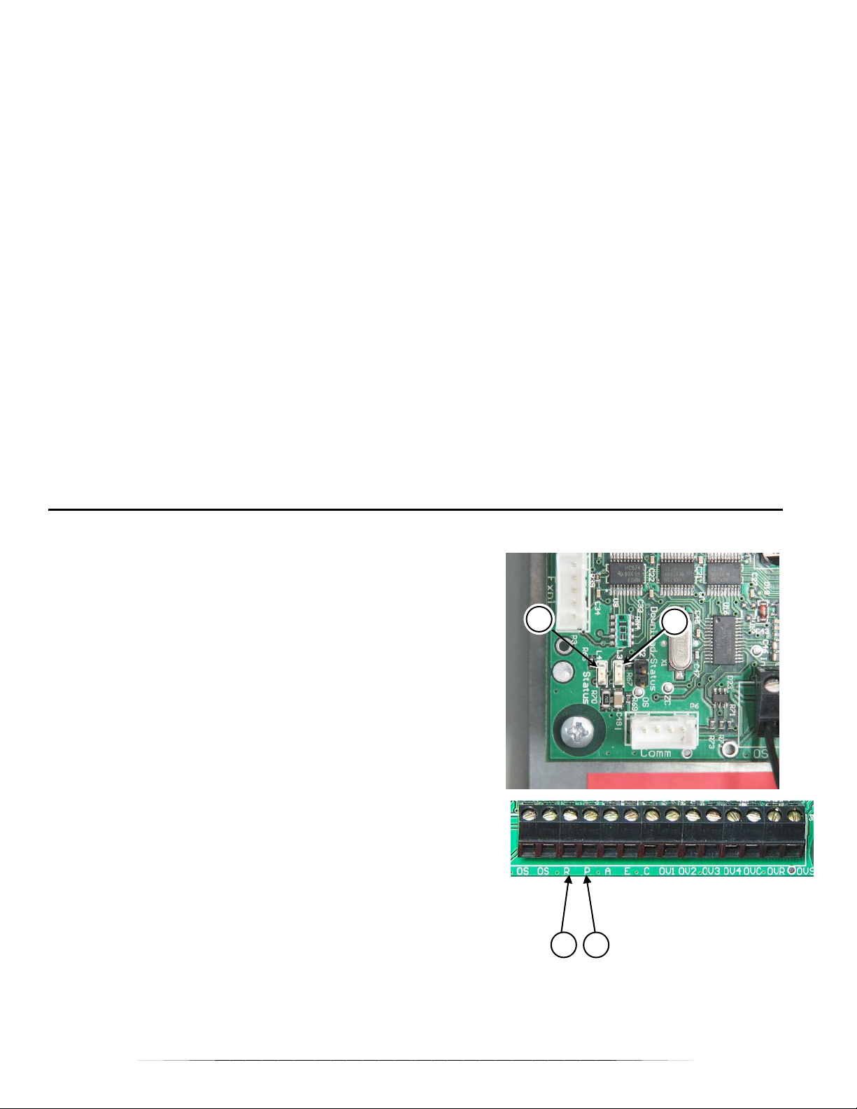
CHECK OUT PROCEDURE FOR TRANSMI T MODE
1. Turn power on to the transceiver.
2. Look at LED-L3, (1). It should blink OFF-and-ON at a rate
based on the outdoor temperature.
3. Look at LED-L4, (2). It may be:
• OFF when receiving an off-peak signal
• ON solid if an override switch is enabled
• blinking OFF and ON according to the type of signal being
received from the control device.
4. Simulate an off-peak period.
• If DIP switch #1 is in the ON position, this can be done by
placing a jumper wire across the R and P terminals.
• If DIP switch #1 is in the OFF position, an open across R
and P will simulate the off-peak period.
5. LED-L4 should be OFF and the relay LED’s should all be ON.
6. Make sure PLC signal is received by each controlled device:
transceiver receiver, Steffes Heating Systems Electric Thermal
Storage (ETS) heater, receivers, and all other controlled loads.
2
1
7. Simulate a peak period.
• If DIP switch #1 is in the OFF position, this can be done by
placing a jumper wire across the R and P terminals.
• If DI P switch #1 is in the ON position, an open across R and P will simulate the peak period.
• Look at the relay LED’s. They should all be OFF.
8. Look at LED-L4. It should be blinking at the peak rate as shown for Peak (P) Signal.
19
R
Page 23
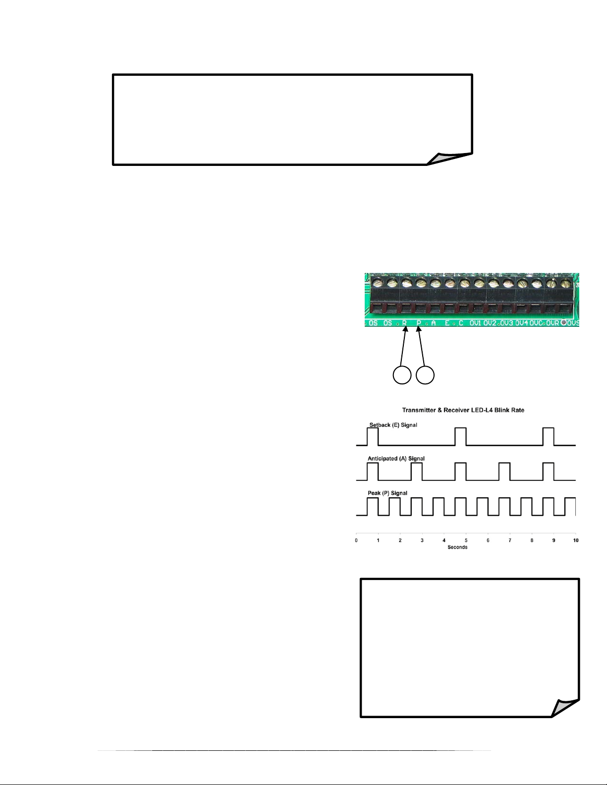
9. Make sure PLC signal is received by each controlled device: transceiver receiver, Steffes Heating
R
P
Systems Electric Thermal Storage (ETS) heater, receivers, and all other controlled loads to ensure that
these loads turn off.
When checkout is complete, make sure:
• DIP switches are all set to the proper position
• jumper wire has been removed
• low voltage connections have been reconnected
• all wiring connections are tight
CHECK OUT PROCEDURE FOR RECEIV E MODE
1. Turn power on to the transceiver.
2. Look at LED-L3. It should blink OFF-and-ON slowly then increasingly faster until it locks ON indicating it
has received PLC signal from the transmitter.
NOTE: It can take 2-3 minutes for PLC signal reception when using a “fast” channel and 7-10
minutes when using a “slow” channel.
3. Look at LED-L4, (2). It may be:
• OFF when receiving an off-peak signal
• ON solid if an override switch is enabled
• blinking OFF and ON according to the type of signal being
received from the control device.
4. Simulate an off-peak period at the transmitting device.
• If DIP switch #1 is in the ON position at the transmitting
device, this can be done by placing a jumper wire across the
R and P terminals.
• If DIP switch #1 is in the OFF position at the transmitting
device, an open across R and P will simulate the off-peak
period.
5. LED 4 should be OFF.
6. The relay LED’s should all be ON.
7. Go to each controlled load (appliance) and make sure it is
operating.
8. Simulate a peak period at the transmitting device.
• If DIP switch #1 is in the OFF position at the transmitting
device, this can be done by placing a jumper wire across
the R and P terminals.
• If DIP switch #1 is in the ON position at the transmitting
device, an open across R and P will simulate the peak
period.
9. Look at the relay LED’s. They should all be off.
10. Look at LED-L4. It should be blinking at the peak rate as
shown.
11. If one of the optional overrides has been installed, verify
proper operation of the override device.
When checkout is complete, make
sure:
• DIP switches are all set to the
proper position
• jumper wire has been removed
from the transmitting device
• all wiring connections are
tight
20
Page 24
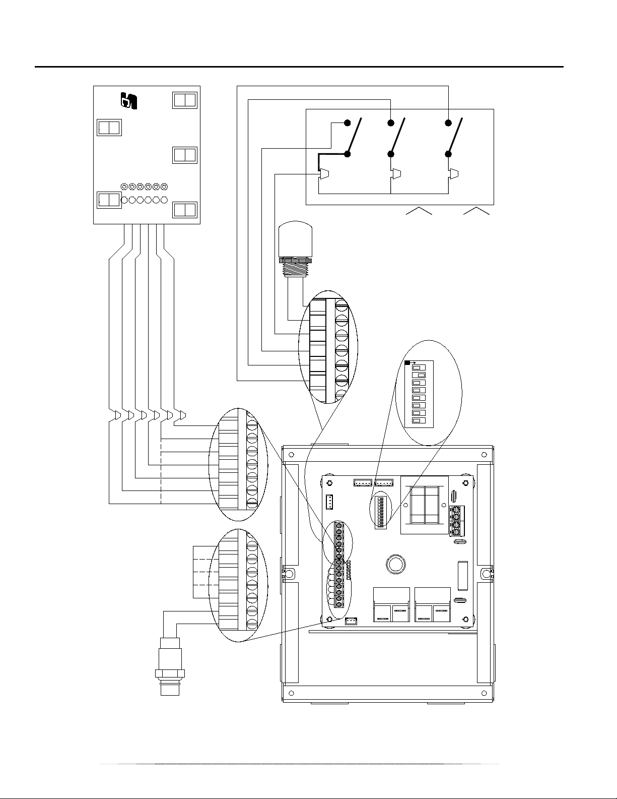
LOW VOLTAGE WIRING DIAGRAM
Override Switch - Orange/Black
OVS
Override Hot - Red
CORPORATION
OVR
STEFFES
OVC
Override Common - Yellow
OV2
OV3
Circuit 4 Override - Violet
OV1
Circuit s 2 & 3 Ove rride - Violet
Circuit 1 Override - Violet
Override Module
Multiple Switch
(OPTIONAL)
(OPTIONAL)
SENSOR
PEAK CONTROL
UTILITY
SWITCH
OUTDOOR
REMOTE
The Power Company.
SWITCH
Is Being Utilized By
PEAK CONTROL
ANTICIPATED
UTILITY
Only if Anticipated Peak
TEMPERATURE
SET BACK
ROOM
Set Back is Optional
Room Temperature
OS
OS
LOW VOLTAGE
CONNECTIONS
R
P
A
DIP SWITCHES
N
O
E
C
76 82 5431
OV1
OV2
OV3
OV4
OVC
OVR
OVS
OV1
OV2
OV3
OV4
OVC
Override Switch
(OPTIONAL)
Push-Button
OVR
OVS
CONNECTIONS
LOW VOLTAGE
21
Page 25
R
P
21
RED
RED
BLACK/WHITE
BLACK
L
N
3
M
L
be ordered from
relays. Doing so is a violation of the Transceiver’s
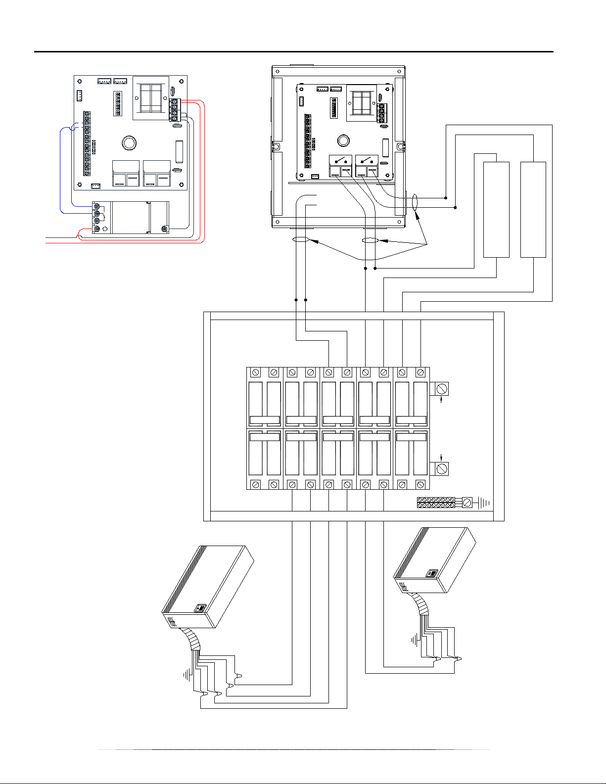
LINE VOLTAGE WIRING DIAGRAM – 2 POLE
2-Pole Indoor Transceiver with
Optional Time Clock Installed
CIRCUIT
RED
CIRCUIT
BOARD
POWER
(This End is
Connected at
Wire Leads.
the Factory).
CIRCUIT
BLACK
1. Tran sce iver with time clock must
2. Tran sce ivers with time clocks installed are not
allowed to have external loads connected to the
UL Listing.
the factory. Time clock cannot be field installed.
16 AWG Black
16 AWG Red
(30 Amp Circuit Maximum)
Factory Installed
(30 Amp Circuit Maximum)
CONTROLLED LOAD
CIRCUIT 2
CONTROLLED LOAD
CIRCUIT 1
GROUNDING AND BONDING NOT SHOWN
5
4
3
2
1
240VAC SOURCE
10
GREEN
BLUE
BLACK
BLUE
OPTION
DUAL
FEED
RED
RED
BLACK
9
8
7
GREEN
6
OPTION
SINGLE
FEED
A RED CIRCUIT.
NOTE:
2103 DO NOT HAVE
MODELS 2102 AND
BLACK
BLACK
RED
BLUE
BLUE
RED
22
Page 26
240V AC SOURCE
BLUE
BLACK
BLUE
BLACK
GREEN
RED
RED
FEED
DUAL
OPTION
9
FEED
OPTION
SINGLE
2103 DO NOT HAVE
A RE D CIRCUIT.
MOD ELS 2102 AND
BLACK
BLACK
BLUE
RED
BLUE
RED
GREEN
NOTE:
8
7
6
CIRCUIT 5
Wire Lead s.
Connected a t
(This End is
the Relays and
Terminal Block.)
the Factory to
Fac tor y Ins talled
GROUNDING AND BONDING NOT SHOWN
CIRC UIT 1 20AMP MAX.
CIRCUITS 2~5 30AMP MAX
4
CIRCUITS
TYPICAL SUPPLY
Red Circuit 1
Black Circuit 1
Red Circuit 2
Black Circuit 2
CONTROLLED LOAD
CONTROLLED LOAD
(20 Am p Circuit Maximum)
(30 Am p Circuit Maximum)
CIRCUIT 3
CIRCUIT 1
3
2
1
REMOVE JUMPER FOR
FIELD CONNECTION.
CT1 CT2
INSTALLED
FACTORY
(OPTIONAL)
CT
CIRCUIT 3
CIRCUIT 4
CIRCUIT 2
CIRCUIT 1
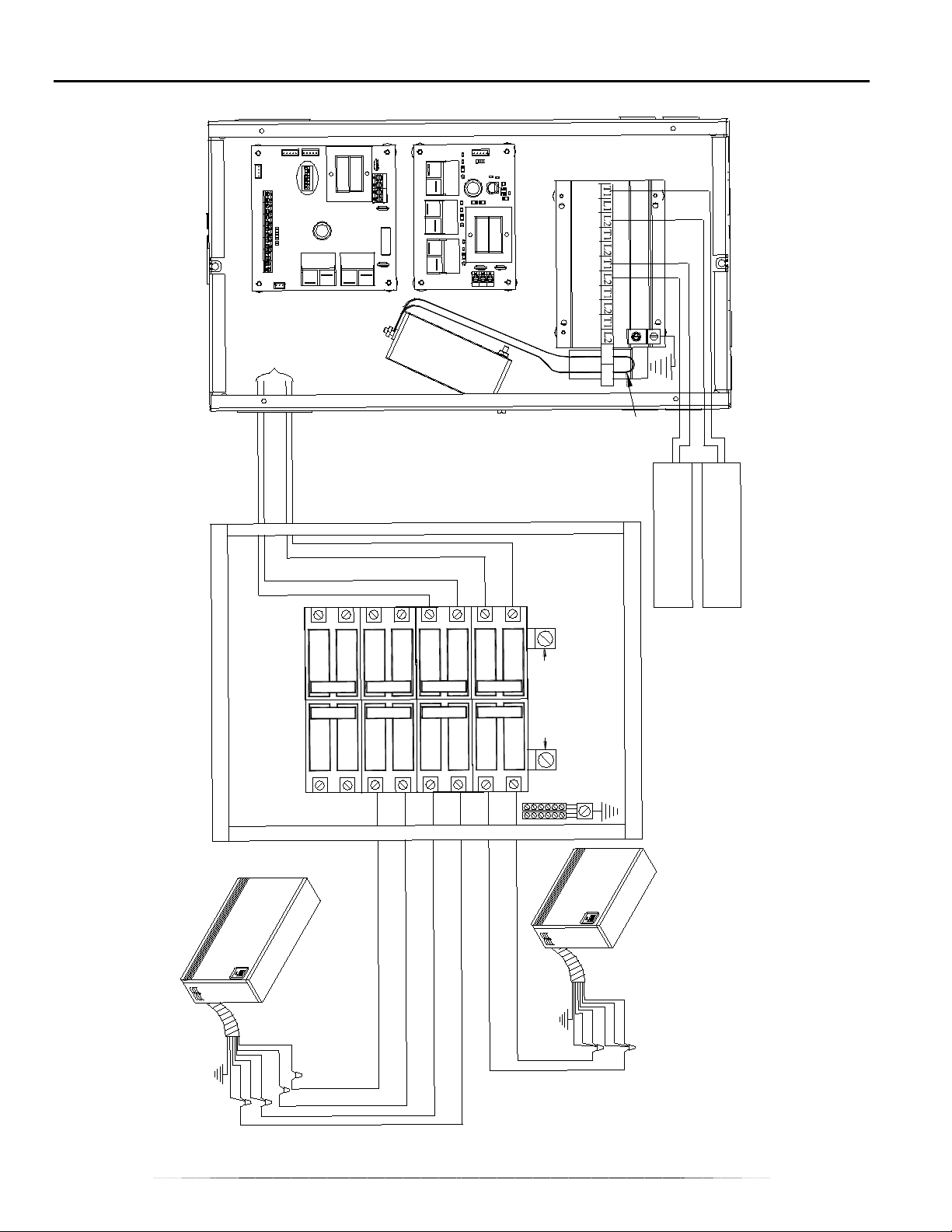
LINE VOLTAGE WIRING DIAGRAM – 5 POLE
23
Page 27
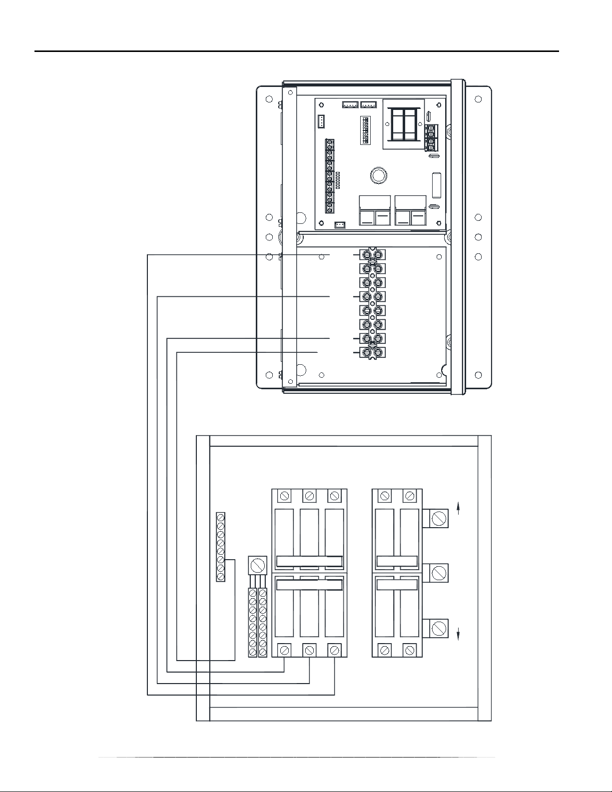
LINE VOLTAGE WIRING DIAGRAM – 3 PHASE
LINE 2
LINE 1
NEUTRAL
LINE 3
3-PHASE
240/208VAC SOURCE
2
20A 3-PHASE
20A 3-PHASE
SEE NOTE 2
SEE NOTE 1
NOTES:
1. Not to Exceed 120 Volts to Ground.
2. Not Used in Single Phase High Power Installation.
1
3
4
30A
30A
GROUNDING AND BONDING NOT SHOWN
24
Page 28

WARRANTY
Steffes Corporation (“Steffes”) warrants that the Steffes Power Line Carrier Transceiver is free fro m
defects in materials and workmanship under normal use and service. Steffes’ obligation under this
Warranty is limited to the repair or replacement of the appliance or parts only which prove to be defective
under normal use within three (3) years of the date of installation and which Steffes’ examination of the
returned device or part(s) shall verify to Steffes’ satisfaction that it is defective. The user shall be
responsible for any labor costs associated with the repair or replacement of the device or part(s) including
the cost of returning the defective appliance or part(s) to Steffes Corporation.
This Warranty is void if the transceiver device is moved from the premises in which it was orig inally
installed. This Warranty shall not apply to a device or part which has been altered in any respect, or
improperly installed, serviced or used, or has been subject to accident, negligence, abuse or misuse.
THE ABOVE WARRANTY BY STEFFES IS EXCLUSIVE AND IN LIEU OF ALL OTHER WARRANTIES,
WHETHER WRITTEN OR ORAL, EXPRESSED OR IM PLIE D, INCLUDING ANY IMPLIED WARRANTY
OF MERCHANTABILITY OR OF FITNESS FO R A PARTICULAR PURPOSE.
The user assumes all risk and liability whatsoever resulting from the use of this transceiver. In no event
shall Steffes be liable for any indirect, special or consequential damages or lost profits.
This Limited Warranty contains the complete and exclusive statement of Steffes’ obligations with respect
to the transceiver and any parts thereof. The provisions hereof may not be modified in any respect except
in writing signed by a duly authorized officer of Steffes.
3050 Highway 22 North
Dickinson ND 58601-9413
© 2009 Steffes Corporation
All Rights Reserved
PRINTED IN USA
1200699 Rev 5
25
 Loading...