

Page 1
WARRANTY
Steffes Corporation (“Steffes”) warrants that the Steffes Power Line
Carrier Mini Receiver is free from defects in materials and workmanship
under normal use and service. Steffes’ obligation under this Warranty is
limited to the repair or replacement of the appliance or parts only which
prove to be defective under normal use within one (1) year of the date of
installation and which Steffes’ examination of the returned device or
part(s) shall verify to Steffes’ satisfaction that it is defective. The user
shall be responsible for any labor costs associated with the repair or
replacement of the device or part(s) including the cost of returning the
defective appliance or part(s) to Steffes Corporation.
This Warranty is void if the device is moved from the premises in which
it was originally installed. This Warranty shall not apply to a device or
part which has been altered in any respect, or improperly installed,
serviced or used, or has been subject to accident, negligence, abuse or
misuse.
THE ABOVE WARRANTY BY STEFFES IS EXCLUSIVE AND IN
LIEU OF ALL OTHER WARRANTIES, WHETHER WRITTEN
OR ORAL, EXPRESS OR IMPLIED, INCLUDING ANY IMPLIED
WARRANTY OF MERCHANTABILITY OR OF FITNESS FOR A
PARTICULAR PURPOSE.
MR7
Operation & Installation Guide
for
Power Line Carrier
Mini Receiver
(Applicable to Software Version 14.0 - 14.9)
The user assumes all risk and liability whatsoever resulting from the use
of this device. In no event shall Steffes be liable for any indirect, special
or consequential damages or lost profits.
This Limited Warranty contains the complete and exclusive statement of
Steffes’ obligations with respect to this device and any parts thereof.
The provisions hereof may not be modified in any respect except in
writing signed by a duly authorized officer of Steffes.
3050 N Highway 22
Dickinson, ND 58601-9413
701-483-5400
“Commitment to Innovation”
DOCUMENT #1200057
“Manufactured in North America”
Off-Peak System Control
Page 2
WARNING
HAZARDOUS VOLTAGE: Risk of electric shock, injury, or
SPECIALTY APPLICATION WIRING DIAGRAM
(six pole configuration utilizing power line carrier signal and an
auxiliary control device)
death. System may be connected to more than one branch
circuit. Disconnect power to all circuits before servicing.
Equipment must be installed and serviced by a qualified
technician.
IMPORTANT
w The equipment described herein is intended for installation by a
qualified technician in accordance with applicable local, state, and
national codes and requirements.
w This manual should be retained by the owner upon completion of the
installation and made available to service personnel as required.
w Disclaimer:
Conditions may occur which cause the power line carrier
transmitter and receivers to have difficulties communicating;
therefore, not operating properly. In no event shall Steffes
Corporation be liable for any indirect, special, or consequential
damages or lost profits.
In compiling this manual, Steffes Corporation has used its best
judgement based upon information available, but disclaims any
responsibility or liability for any errors or miscalculations
contained herein, or any revisions hereof, or which result, in
whole or in part, from the use of this manual or any revisions
hereof.
Grounding and Bonding is not shown in this Diagram.
In This Example, Circuits 4,5,&6
are Controlled by PLC Signal Only
CONTROLLED LOAD
CIRCUIT 6
CONTROLLED LOAD
CIRCUIT 5
CONTROLLED LOAD
CIRCUIT 4
CONTROLLED LOAD
CIRCUIT 3
CONTROLLED LOAD
CIRCUIT 2
CONTROLLED LOAD
CIRCUIT 1
Optional Auxiliary Control
(i.e. room thermostat)
This Device MUST be Grounded.
T1 L2
CIRCUIT 1
Low Voltage
Terminal Strip
T1L1
CIRCUIT 2T1CIRCUIT 3
120
L1
CTS 206-8
9504
N
O
3
21 65 7 84
109
CR2
CR3
CR1
COM
240
CR4
L2
CIRCUIT 5 CIRCUIT 6
CIRCUIT 4
In This Example,
Circuits 1, 2, and 3 are
CR5
CR6
Controlled by PLC Signal
and by an Optional
Auxiliary Control.
L2L2T1
T1T1L2L2
FOR CUSTOMER USE
Please record the serial number of the mini receiver below. This information
is located inside the mini receiver enclosure. Retain this information for
future reference.
Serial No.________________________________________________
9
Page 3

NOTES
(For reference to these notes, refer to the wiring diagrams on
Pages 6 and 7 in this manual.)
NOTE 1: For more information on the dip switches, refer to the Dip Switch
Settings section in this manual.
NOTE 2: Mini receiver configuration must be specified at the time of factory
order.
NOTE 3: The mini receiver operates on 120V or 208V/240V, single phase. In the
single and double pole configuration mini receivers, line voltage
connections must be made in the terminal block to configure it to the
voltage input being connected to. The six pole configuration mini
receiver is factory configured to operate on 208V/240V. If connecting it
to 120V, the line voltage connections in the terminal block must be
reconfigured and L1 must be the ungrounded leg.
NOTE 4: All line voltage wiring in this device must remain below and in front of
the line voltage barrier inside the mini receiver enclosure.
NOTE 5: In the 6-pole mini receiver, circuit 1 feeds both output circuit 1 and the
mini receiver’ s internal controls.
NOTE 6: With the 6-pole mini receiver, loads connected between L1 & L2 on
circuit 1 will be uninterrupted. Loads connected between T1 & L2 on
circuit 1 will be interrupted.
NOTE 7: Circuit 1 maximum fuse size is 20 amps. Maximum load is 16 amps.
Any loads requiring greater than a 20 amp circuit MUST never be
connected to circuit 1.
GENERAL OPERATION
The Steffes Power Line Carrier (PLC) Mini Receiver is designed to provide
wireless control of one electrical circuit (single pole configuration), two electrical
circuits (double pole configuration), or six electrical circuits (six pole
configuration). It receives signals through the existing power lines from the
Steffes Power Line Carrier (PLC) Transmitter or Comfort Control Relay Panel
(CCRP). The built-in 30 AMP relay(s) are capable of controlling devices such as:
ETS heaters, water heaters, baseboards, electric furnaces, dryers, dishwashers, hot
tubs, ceiling cables, or other electrical equipment. When the mini receiver receives
a signal, its relay(s) are activated to control the device(s) connected to them. This
type of control can minimize the overall cost of controlling electrical devices.
FEATURES
w One, two, or six DC held, 30 AMP, board mounted relay(s) pre-wired with 10
AWG leads. (Configuration must be specified at the time of factory order.)
w Single and double pole configurations are UL and cUL safety listed.
w Receives peak and anticipated peak (pre-peak) control signals via the power
lines from the Steffes PLC transmitter system.
w Fifteen selectable communication channels.
w Capable of controlling a device on a rate/control strategy separate from the
master control.
w All configurations are available in metal, flush or surface, indoor mounted
enclosures with power company seal/lockout provision.
Single and Double Pole Configurations: 6” x 6” x 3” (Outdoor enclosure
available as special a factory order.)
Six Pole Configuration: 10” x 13” x 3”
NOTE 8: Circuits 2-6 maximum fuse is 30 amps. Maximum load is 24 amps.
Maximum Fuse Size (6-pole) Total Input Circuit Ampacity (6-pole)
Circuit 1 = 20 AMP
(16 AMP Load, Max)
Circuit 2-6 = 30 AMP
(24 AMP Load, Max)
NOTE 9: To ensure proper communications between the PLC Mini Receiver and
it’ s correlating transmitter, the mini receiver MUST be grounded. The
system grounding and bonding must be sized and installed in
compliance with all applicable codes.
8
Surface Mounted = 120 AMPS
Flush Mounted = 80 AMPS
Maximum Fuse Size (6-pole) Total Input Circuit Ampacity (6-pole)
Circuit 1 = 20 AMP
(16 AMP Load, Max)
Circuit 2-6 = 30 AMP
(24 AMP Load, Max)
w Controls 120V or 208V/240V, single phase devices connected to single or
three phase systems.
w Indicator lights to monitor PLC operation or relay status.
w Optional 90-minute peak override module available.
Surface Mounted = 120 AMPS
Flush Mounted = 80 AMPS
1
Page 4
INDICATOR LIGHTS
In its standard configuration, when the mini receiver is first energized, a red light
on the circuit board will begin to flash slowly. This indicates the receiver is
waiting for a signal. When valid bits of information are received, the light will
begin flashing more rapidly. There may be occurrences where the light will switch
from a fast flash back to a slow flash. After several minutes, the mini receiver will
synchronize with the transmitter, and the light will illuminate continuously to
indicate complete information is being received. This red light monitors power
line carrier (PLC) communication as follows:
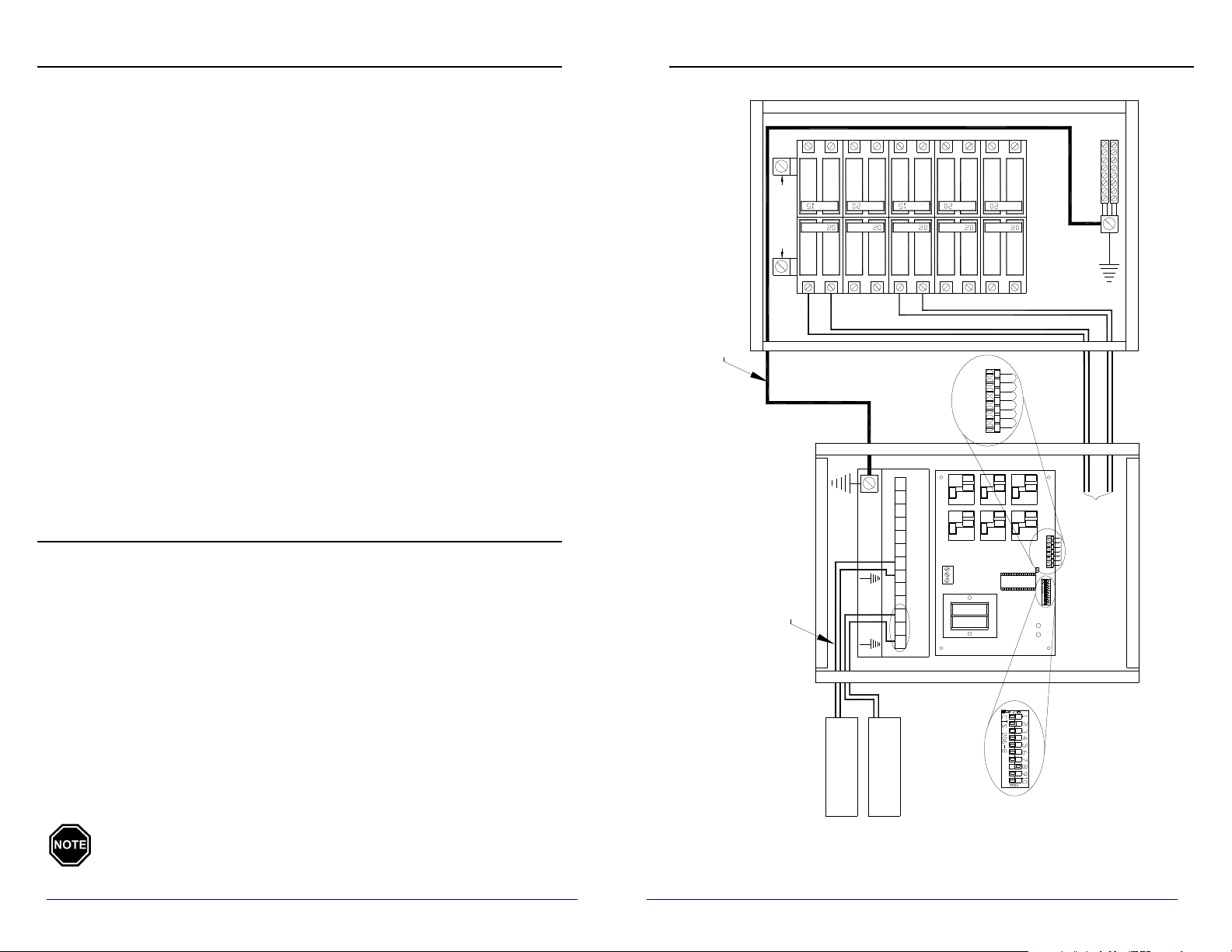
TYPICAL SYSTEM WIRING DIAGRAM
(six pole configuration)
6
8
7
9
10
Slow Flash: Mini receiver is waiting for PLC communication.
Fast Flash: Mini receiver is receiving partial PLC communication.
Continuous Illumination: Mini receiver is receiving complete PLC
information
There is also an amber indicator light on the circuit board. This light is used to
indicate whether the relays are open or closed. It will also indicate if a peak
override has been initiated. The amber light monitors the status of the relays as
follows:
No Illumination: relay(s) open
Flashing: overrride enabled
Continuous Illumination: relay(s) closed
These lights can only be seen when the mini receiver enclosure is open. They are
not accessible to the user in normal operation.
OVERRIDE OPTION (Power Company Permitting)
The mini receiver is available with a 90-minute override option. If the override is
incorporated, it allows the use of a normally controlled device(s), such as a water
heater, during a peak control time. It allows for a single override of either all
connected circuits or a one zone override of circuits 1, 3, 5, and 6. This feature
works well in areas using a Time-of-Use rate/control strategy. (Installation
instructions for this feature are provided with the override module, item
#1302070.)
240VAC SOURCE
1
2
SYSTEM GROUND
(See Note 9)
(See Note 4)
4
3
LOW VOLTAGE
TERMINAL STRIP
CIRCUIT 6
T1 L2L2
CIRCUIT 5
T1 L2 T1
CIRCUIT 4
240
120
L1
CIRCUIT 3
CIRCUIT 2
T1L2L1 T1 L2L2
CIRCUIT 1
T1
(See Note 6)
5
CR6
CR5
CR4
CR3
CR2
CR1
COM
(See Note 3)
CIRCUITS
(See Note 5)
TYPICAL SUPPLY
CR6
CR5
CR4
CR3
CR2
CR1
COM
Red Circuit 3
Red Circuit 1
Black Circuit 1
Black Circuit 3
Factory installed wire leads.
to the relays and terminal block.)
(This end is connected at the Factory
An override period can be initiated during a “peak” period or if communication
between the transmitter and mini receiver is lost. To do so, press and hold the
override button for 2 seconds. A new 90-minute override period can be initiated
any time during a current override cycle. When an override is initiated, it cannot
be cancelled manually. The override will cancel itself at the end of the 90-minute
override cycle or at the start of the next off-peak period, whichever comes first.
The position of dip switch #8 on the mini receiver circuit board will
determine which relays are enabled when an override is initiated.
(For more information, refer to the Dip Switch Settings section in
this manual.)
2
(See Note 1)
CIRCUIT 3
CIRCUIT 1
(See Note 8)
CONTROLLED LOAD
(See Note 7)
CONTROLLED LOAD
DIP SWITCHES
For reference to the “NOTES” listed in this diagram, refer to the Notes
section on page 8 in this manual.
7
Page 5
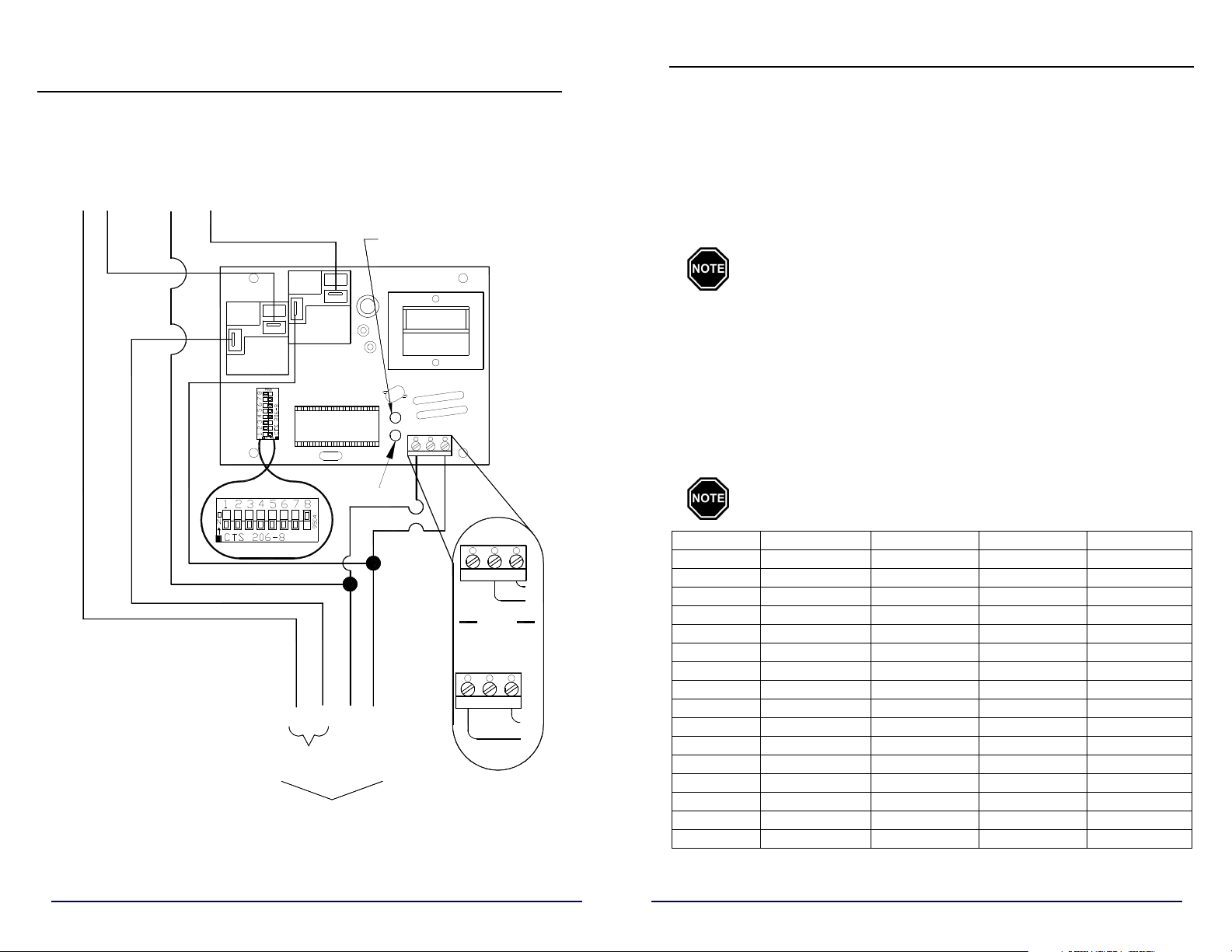
LINE VOLTAGE WIRING AND CIRCUIT BOARD
CONFIGURATION DIAGRAM
(single pole or double pole configuration)
This Device MUST be Grounded.
Grounding and Bonding is not shown in this Diagram.
TO
CONTROLLED
LOAD # 2
BLACK
TO
CONTROLLED
LOAD # 1
BLACK
OVERRIDE
LIGHT
DIP SWITCH SETTINGS
DIP SWITCH 1: ANTICIPATED PEAK (PRE-PEAK) OPERATION MODE
This dip switch determines how an anticipated peak (pre-peak) signal will affect
the mini receiver’ s relay(s). For power companies desiring to control loads
separately using multiple signals, this dip switch can be used to do peak control
of devices on a separate rate/control strategy.
FACTORY DEFAULT SETTING = OFF
Off = Relay(s) will not respond to an anticipated peak (pre-peak) signal.
On = Relay(s) will be activated by an anticipated peak (pre-peak) signal.
The peak signal is priority signal. When a peak signal is being
received, no other signal will be recognized.
RED
RED
DIP SWITCHES
30 AMP
RELAY 2
(See Note 1)
30 AMP
RELAY 1
MICROPROCESSOR
INDICATOR
LIGHT
TRANSFORMER
120 VOLT
240 120 L1
OR
208/240 VOLT
SPECIAL
277V
( )
ORDER
240 120 L1
////
2-POLE OPTION
(See Note 2)
(See Note 4)
For reference to the “NOTES” listed in this diagram, refer to the Notes
section on page 8 in this manual.
LINE VOLTAGE
CONNECTIONS
(See Note 3)
L1
L2
L1
L2
DIP SWITCH 2, 3, 4 & 5: PLC CHANNEL SELECTION
The mini receiver can receive information on one of fifteen channels, depending
on which channel the transmitting device is set to transmit on. The mini receiver
and the transmitting device MUST be set to the same channel for proper
communication to occur.
To select the Power Line Carrier channel desired, use the chart below and set dip
switches 2, 3, 4,and 5 to the proper positions.
FACTORY DEFAULT SETTING = No PLC Channel selected (2 OFF, 3 OFF, 4
OFF, 5 OFF)
A specific channel must be selected at time of installation.
HANNEL DIPSWITCH 2 DIPSWITCH 3 DIPSWITCH 4 DIPSWITCH 5
C
0 OFF OFF OFF OFF
1 ON OFF OFF OFF
2 OFF ON OFF OFF
3 ON ON OFF OFF
4 OFF OFF ON OFF
5 ON OFF ON OFF
6 OFF ON ON OFF
7 ON ON ON OFF
8 OFF OFF OFF ON
9 ON OFF OFF ON
10 OFF ON OFF ON
11 ON ON OFF ON
12 OFF OFF ON ON
13 ON OFF ON ON
14 OFF ON ON ON
15 ON ON ON ON
6
3
Page 6

DIP SWITCH SETTINGS CONTINUED….
DIP SWITCH SETTINGS CONTINUED….
DIP SWITCH 6: AUTOMATIC SHOULDER CHARGE
(Specialty Applications Only)
This dip switch allows for a shoulder charge period for the device controlled on
relay #1. Five (5) hours after a peak signal is received, relay #1 will close for
four (4) hours if the outdoor temperature is below 35 degrees Fahrenheit. The
relay will then open again and will remain open until an off-peak or anticipated
peak signal is received. If an off-peak or anticipated peak signal is received
during the five hour period, the timer will reset.
FACTORY DEFAULT SETTING = OFF
Off = Shoulder charging disabled
On = Shoulder charging enabled
The duration of the delay and the outdoor temperature settings
are preset at the factory. If you have an application which
requires a change to these settings, please contact the factory.
DIP SWTICH 7: DEFAULT RELAY STATUS
This dip switch determines how the relay(s) will respond when the power line
carrier control system is first energized or if the mini receiver loses signal from
the transmitter.
FACTORY DEFAULT SETTING = OFF
Off = The relay(s) will open until a signal is received from the PLC
transmitter.
On = The relay(s) will close until a signal is received from the PLC
transmitter.
DIP SWITCH 8: PEAK CONTROL OVERRIDE
With the addition of the override module to the mini receiver, peak override of
some or all of the circuits is possible. Depending upon the position of this dip
switch, either all circuits in the mini receivers or just those connected to relays 1,
3, 5, and 6 can be used in 90-minute intervals during a peak control period, if
desired.
FACTORY DEFAULT SETTING = ON
Off = Circuits connected to relays 1, 3, 5, and 6 are enabled during a peak
control time when an override cycle is initiated.
On = All circuits in the mini receiver are enabled during a peak control
time when an override cycle is initiated.
4
DIP SWITCH 9: RELAY 3 AND 4 FUNCTION SELECTOR
(Six Pole Configurations Only)
This dip switch is used in conjunction with dip switch 6. If dip switch 6 is in
the on position, the position of dip switch 9 will determine how relays 3 and 4
will respond.
FACTORY DEFAULT SETTING = OFF
Off = Relays 3 and 4 will function like relay 2
On = Relays 3 and 4 will function like relay 1
DIP SWITCH 10: RELAY 5 AND 6 FUNCTION SELECTOR
(Six Pole Configurations Only)
This dip switch is used in conjunction with dip switch 6. If dip switch 6 is in
the on position, the position of dip switch 10 will determine how relays 5 and
6 will respond.
FACTORY DEFAULT SETTING = OFF
Off = Relays 5 and 6 will function like relay 2
On = Relays 5 and 6 will function like relay 1
INSTALLER’S FINAL CHECK OUT PROCEDURE
_____ 1. Prior to energizing the electrical circuit feeding the mini receiver,
inspect all field installed electrical connections to ensure they are tight
and that all wires are routed correctly. All line voltage wiring must
remain below and in front of the line voltage barrier inside the mini
receiver. To ensure proper communication with the PLC transmitter,
the mini receiver must be grounded.
____2. Check the settings of the dip switches on the mini receiver board to
ensure they are in the correct positions for the application.
The desired PLC channel MUST be selected for communication to
occur.
_____ 3. Check to ensure that the red indicator light on the mini receiver circuit
board is illuminated continuously indicating communication is
occurring between the transmitter and the mini receiver.
Communications between the transmitter and the mini
receiver occur on a continuous basis. Upon energizing a
system, there will be some delay in a receiver’s response to
transmitter signals. It takes approximately seven (7)
minutes for the transmitter to establish initial
communication. Subsequent communication will occur
more rapidly.
____ 4. Once good communication is established, verify that the mini receiver
responds correctly to the corresponding utility peak signal status. The
amber indicator light will illuminate when the relay(s) are closed and
should remain off when the relay(s) are open.
5
 Loading...