

Page 1
OWNER'S AND
INSTALLER'S MANUAL
V3
Models: 8150, 8155, 8180, 8185, 8188
Applicable to Software Version 2.0
LISTED
Page 2
IMPORTANT
The equipment described herein is intended for installation by a qualified
technician in accordance with applicable local, state, and national codes and
requirements.
To insure proper installation and operation of this product, completely read all
instructions prior to attempting to assemble, install, operate, maintain or repair
this product. Upon unpacking of the system, inspect all parts for damage prior
to installation and start-up.
This manual should be retained by the owner upon completion of the installa-
tion and made available to service personnel as required.
Disclaimer: In compiling this manual, Steffes Corporation has used its best
judgement based upon information available, but disclaims any responsibility
or liability for any errors or miscalculations contained herein, or any revisions
hereof, or which result, in whole or in part, from the use of this manual or any
revisions hereof.
Steffes disclaims any responsibility or liability for mold/mildew growth and/or
any damages caused by either. We strongly recommend that the user follow
the moisture, mold and mildew prevention guidelines prescribed by local or
national protection agencies.
For Customer Use
Please record your model and serial number below. This number is found on the identification labels
located on the front of and inside the electrical panel. Retain this information for future reference.
Model No. ________________________________________________________________________
Serial No. ________________________________________________________________________
RECOGNIZE THESE SYMBOLS AS SAFETY PRECAUTIONS
It is important, both for your personal safety and to avoid possible damage to the
equipment and your property, that you observe the safety instructions given following
these symbols.
Page 3
SAFETY PRECAUTIONS
1. DO NOT energize the system while disassembled or
without ceramic heat storage brick in place.
2. DO NOT use or store materials that may produce explosive or flammable gases near the system.
3. DO NOT violate the placement and clearance requirements specified in this manual. (Page 3.03)
4. DO NOT place anything on top of the Storage Module(s).
5. Disconnect power to all circuits before servicing. This
heating system may be connected to more than one branch
circuit.
6. Installation of and/or service to this heating system should
be performed by a qualified technician in accordance with
information contained herein and with national, state, and
local codes and requirements.
7. A repeated message of “CORE FAIL” indicates a need
for service by a qualified technician.
WARNING
Hazardous Voltage: Risk of elec-
tric shock, injury, or death. This
system may be connected to
more than one branch circuit.
Disconnect power to all circuits
before installing or servicing.
Installation of and/or service to
this equipment MUST be performed by a qualified technician.
Risk of injury or fire. Violation of
the clearance requirements can
cause improper operation of the
equipment. Maintain the placement and clearance requirements
specified.
BUILT-IN SAFETY DEVICES
The ThermElect heating system incorporates safety devices to ensure normal operating temperatures are maintained. The chart below describes these safety devices.
DEVICE NAME FUNCTION
Core Charging High
Limit Switches
(Auto Reset)
These limit switches monitor the core and top temperatures.
If normal operating temperatures are exceeded, the system
will display "CORE FAIL" and the elements will not be
allowed to operate.
Core Blower
Limit Switch
(Auto Reset)
Supply Air Blower
Limit Switch
(Manual Reset)
This limit switch monitors the discharge air temperature
and interrupts power to the core blower if the normal
operating temperature is exceeded:
o
160
F / 71oC (nominal)
This limit switch monitors the discharge air temperature
and interrupts power to both the supply air blower and the
core blower if the normal operating temperature is exceeded:
o
190
F / 88oC (nominal)
Core Blower Housing
Temperature Limit
Switch (Auto Reset)
This limit switch monitors the temperature in the base of the
air handler and interrupts power to the core blower if the
normal operating temperature is exceeded:
o
160
F / 71oC (nominal)
LOCATION
ON SYSTEM
Air handler side of
each storage module
and storage module top
panel.
Mounted on limit
bracket at discharge
air outlet.
Mounted on limit
bracket at discharge
air outlet.
In the base of the air
handler near the core
blower.
THERMELECT SAFETY INFORMATION
Page 4

Table of Contents
TC
Operation
General Operation ........................................................................................................................................................................ 1.01
System Use During Construction Phase......................................................................................................................................1.01
System Start-Up ........................................................................................................................................................................... 1.01
Turning System "OFF" and "ON" ............................................................................................................................................... 1.01
Control Panel ............................................................................................................................................................................... 1.02
Operating Status .......................................................................................................................................................................... 1.02
Temperature Control .................................................................................................................................................................... 1.03
Brick Core Charge Control ........................................................................................................................................................... 1.03
Charge Control Override .............................................................................................................................................................. 1.03
Maintenance and Cleaning .......................................................................................................................................................... 1.03
Optional Accessories
Load Management Control .......................................................................................................................................................... 2.01
External Duct Sensor.................................................................................................................................................................... 2.02
Lifting Handles ............................................................................................................................................................................ 2.02
Installation
Shipping and Packaging .......................................................................................................................................................3.01-3.02
Placement and Clearance Requirements....................................................................................................................................... 3.03
Initial Set-up ................................................................................................................................................................................. 3.04
Attaching Storage Module(s) to Air Handler .......................................................................................................................3.04-3.05
Electrical Panel Installation ...................................................................................................................................................3.06-3.07
Brick Loading ........................................................................................................................................................................3.07-3.08
Heating Element Installation ........................................................................................................................................................ 3.08
Brick Core Temperature Sensor Installation -............................................................................................................................... 3.09
Air Conditioner/Heat Pump Interface........................................................................................................................................... 3.09
Ducting ........................................................................................................................................................................................ 3.10
Line Voltage Electrical Connections ............................................................................................................................................ 3.10
Outdoor Temperature Sensor Installation.................................................................................................................................... 3.11
Thermostat Connections ......................................................................................................................................................3.11-3.12
Electronic Air Filter Installation ................................................................................................................................................... 3.14
Installer's Final Check-Out Procedure .......................................................................................................................................... 3.14
Load Management Control
On-Peak/Off-Peak Program ...................................................................................................................................................4.01-4.02
4-20 Milliamp Control (1-5 Volt DC) ............................................................................................................................................. 4.02
Pulse Monitoring ......................................................................................................................................................................... 4.03
Appendix
Specifications..................................................................................................................................................................... A.01-A.03
Typical System Line Voltage Wiring Diagrams.................................................................................................................. A.04-A.05
Internal System Wiring Diagram - Low Voltage ..........................................................................................................................A.06
Help Menu .................................................................................................................................................................................. A.07
Error Codes ........................................................................................................................................................................ A.07-A.09
Warranty
TABLE OF CONTENTS THERMELECT
Page 5

1
Operation
GENERAL OPERATION
The ThermElect heating system stores off-peak electricity in the form of heat. Off-peak electricity is available
during times of the day or night when electricity is plentiful and the associated costs are low.
Operation of the heating system is automatic. During off-peak hours, the system converts electricity to heat which
is then stored in its ceramic brick core. The amount of heat stored in the brick core of the Storage Module(s)
varies in relation to outdoor temperature, current building load, utility peak conditions, and/or the heating requirements.
A heat call from the thermostat or main system control energizes the blowers in the system. The variable speed
core blower automatically adjusts its speed to circulate air through the brick core. The supply air blower then
delivers the heated air into the desired area through the duct system to maintain constant, comfortable temperature.
The versatility of this system allows it to fit many applications. The system is designed for use as either a sole
heating source (“stand alone” furnace) for make up air heating or as a supplement to another ducted heating
system such as a heat pump.
SYSTEM USE DURING CONSTRUCTION PHASE
Like most heating equipment manufacturers, Steffes strongly recommends that “Construction Heating Units” be
used instead of the permanent heating system during the construction phase. Use of the permanent heating system
during this phase may contaminate the duct system and/or internal areas of the heating system. This may cause
poor indoor air quality issues and/or improper system operation or equipment damage.
Operation
SYSTEM START-UP
On start-up of the system, odors relating to first time operation of the heating components may be experienced.
Also, if not used for an extended period of time, dust may accumulate in the system. Allow the heating system to
charge to its maximum brick core charge level to expel odors in a timely manner.
As with most heating systems, air borne particles and odors may be drawn into the system and oxidized. Odors
can be amplified; thus, it is not recommended to operate the system if odors such as those from paints,
varnishes, or chemicals are present in the air. Air borne particles, which have been oxidized, are expelled
back into the room and may accumulate on air vents or other surfaces. Over time, these particles may appear as a
black residue, commonly referred to as soot. High concentrations of air borne particles from aerosols, dust,
candles, incense, pet hair, smoke, or cooking can contribute to poor indoor air quality and accelerate the sooting
process.
During operation, the heating system may produce minor expansion noises. These noises are the result of the
internal components reacting to temperature changes.
TURNING SYSTEM "OFF" AND "ON"
The system is fully automatic and does not need to be manually disabled. Talk to your installer or energy management person for additional information.
THERMELECT OPERATION 1.01
Page 6
CONTROL PANEL
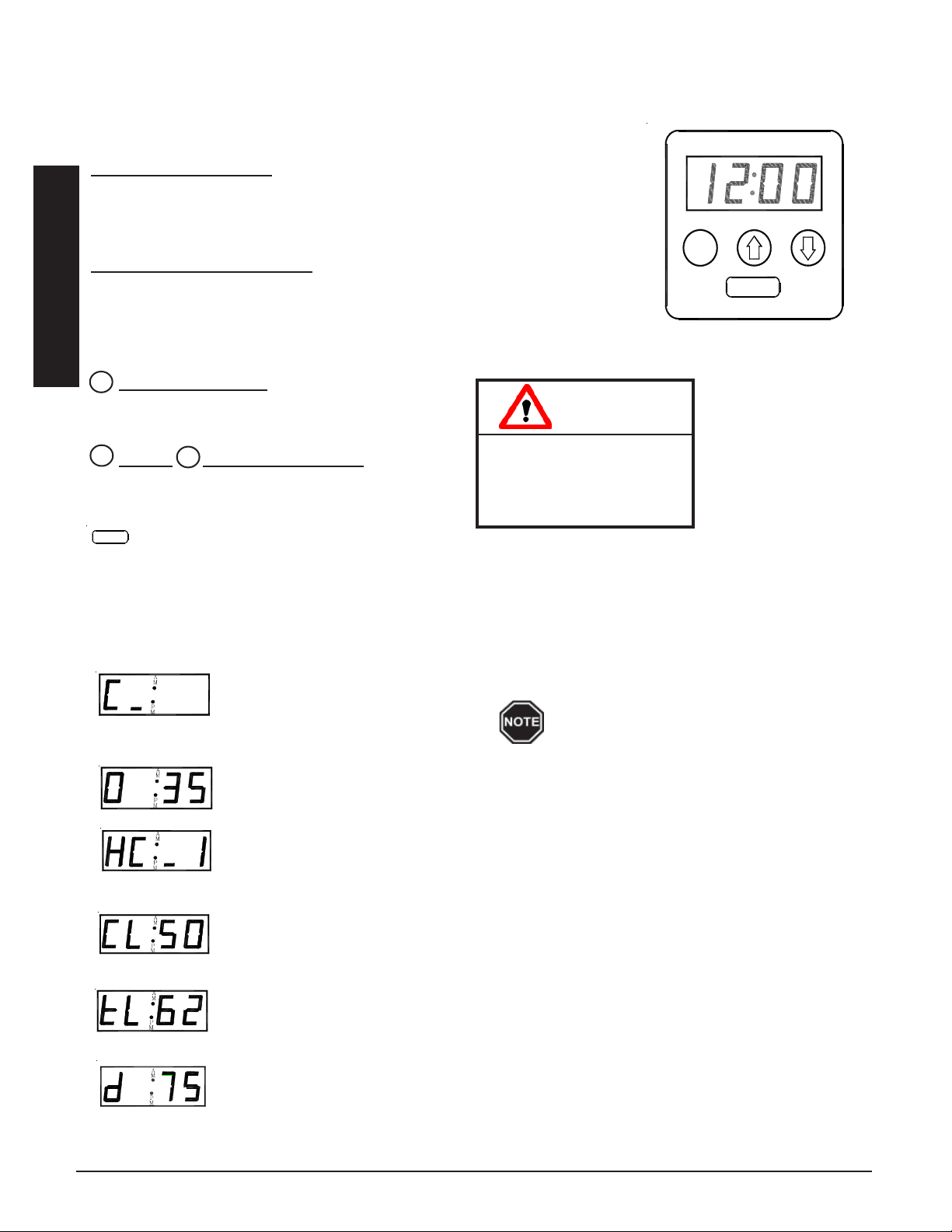
Operation of the ThermElect system is automatic. All operational functions are stored in its microprocessor in
function locations and are factory preset. If necessary, the installer can adjust them through the control panel.
(See Figure 1.)
AA
Four-Digit LED Display
The four digit LED displays specific operating information. During an editing
process, the function locations and the values set in these locations are displayed
for viewing and adjusting purposes.
STEFFES CORPORATION
MM
PP
MM
M
AM and PM Indicator Lights
The AM and PM indicator lights are only utilized if the Steffes Time Clock Module
is being installed. With this module installed, the system displays time on AM/PM
Operation
intervals and the corresponding light flashes. The system can be configured to
display military time, in which case both the AM and PM lights illuminate.
M
Mode (Edit) Button
Activates the editing menu for changing the operating
CAUTION
information of the system.
×
Up and Down Arrow Buttons
Ø
Used to scroll up or down when viewing or changing
operating functions.
Editing operating
information may alter
the performance and
operation of the system.
CONTROL PANEL
FIGURE 1
Interface Port
FOR SERVICE USE ONLY! Allows technician external access for updating software and troubleshooting.
OPERATING STATUS
The ThermElect system is set to display various operating information as described below. Press and release the
up arrow to view this data.
Operating Mode - Indicates the current operating mode of the system.
C = Off-Peak (Charge) Time
P = On-Peak (Control) Time
A = Anticipated Peak Time
Outdoor Temperature -“O” followed by a number indicates current outdoor temperature.
Heat Call Status - Indicates the current heat call status being received from the room thermostat.
HC_0 = No Heat Call HC_1 = Stage 1 Heat Call
HC_2 = Stage 2 Heat Call HC_3 = Emergency Heat
COOL = Cooling/Air Conditioning Call
Brick Core Charge Level - “CL” (charge level) followed by a number indicates the current
percentage of heat stored in the brick core. “CL:_” represents zero percent and “CL: F” represents a full core charge level.
A bar illuminates on the lower portion of
the display's second digit whenever one or
more heating elements are energized.
Targeted Brick Core Charge Level - “tL” (target level) followed by a number indicates the
current percentage of brick core charge being targeted by the system. A display of “tL:_” indicates a target level of zero percent and “tL: F” indicates a full core charge target level.
Load Control - Current demand (kW) divided by 10. A value of "d 75" is equal to a current
demand of 750kW.
OPERATION 1.02 THERMELECT
Page 7

TEMPERATURE CONTROL
Temperature set point is adjusted at the wall thermostat(s) or the main system control. If temperature in the area
drops below the desired set point, a heat call is initiated and the blower in the ThermElect system is energized.
The variable speed core blower automatically adjusts speed in relation to brick core temperature and duct temperature to circulate air through the brick core. The supply air blower then delivers the heated air into the desired
area through the duct system to satisfy heating requirements.
When used to supplement heat pump systems, the ThermElect system replaces resistance strip heat, which is
typically required as a supplement or back-up to the heat pump system. The outlet sensor monitors the discharge
air temperature. If the demand for heat is at a point where the heat pump alone cannot maintain the desired duct
temperature, stored heat is used to supplement the heat pump and satisfy the heating requirements.
When the ThermElect system receives a “G” call, the supply air blower is energized; however, no heat is delivered as this is a “fan only” call.
When a “G” call is received with a “Y” call, the supply air blower is energized and the minimum discharge air
temperature (as set in Location 48) is targeted.
Anytime the ThermElect system receives a “W” call with any other call from the thermostat (except “O”) then
the maximum discharge air temperature (as set in Location 49) is targeted. The maximum discharge air temperature is also targeted if the current outdoor temperature (shown in Location 109) is lower than the off-peak lock out
temperature (set in Location 46) or the on-peak lockout temperature (set in Location 47).
Reference the Supplemental Installer's Guide for more information on system operation.
BRICK CORE CHARGE CONTROL
The amount of heat stored in the brick core of the Storage Module(s) varies in relation to outdoor temperature,
current building load, utility peak conditions, and/or the heating requirements. The outdoor sensor, supplied with the
system, monitors outdoor temperature and provides this information to the system. As the outdoor temperature
decreases, heating requirements increase and the system stores more heat accordingly.
CHARGE CONTROL OVERRIDE
If desired, the ThermElect system can be programmed to allow a charge control override. This override allows the
user to force the system to target a full core charge level and can be initiated or cancelled at any time. If an
override is initiated, the system targets a full core charge level during the next off-peak period. It continues to
charge during off-peak hours until it achieves full (maximum) core charge or until the override is cancelled. Once
full charge is achieved or the override is cancelled, the system charges according to the standard configuration.
Operation
MAINTENANCE AND CLEANING
Any air filter(s) in the system should be replaced on a regular basis to ensure proper operation and to maintain
overall efficiencies. No additional routine maintenance is required.
If utilizing a heat pump or air conditioning system with the ThermElect system, the indoor coil should be cleaned
periodically as dirt accumulation may reduce system efficiency. It is important to follow the manufacturer’s
maintenance and cleaning recommendations for these devices.
THERMELECT OPERATION 1.03
Page 8
2
Optional Accessories
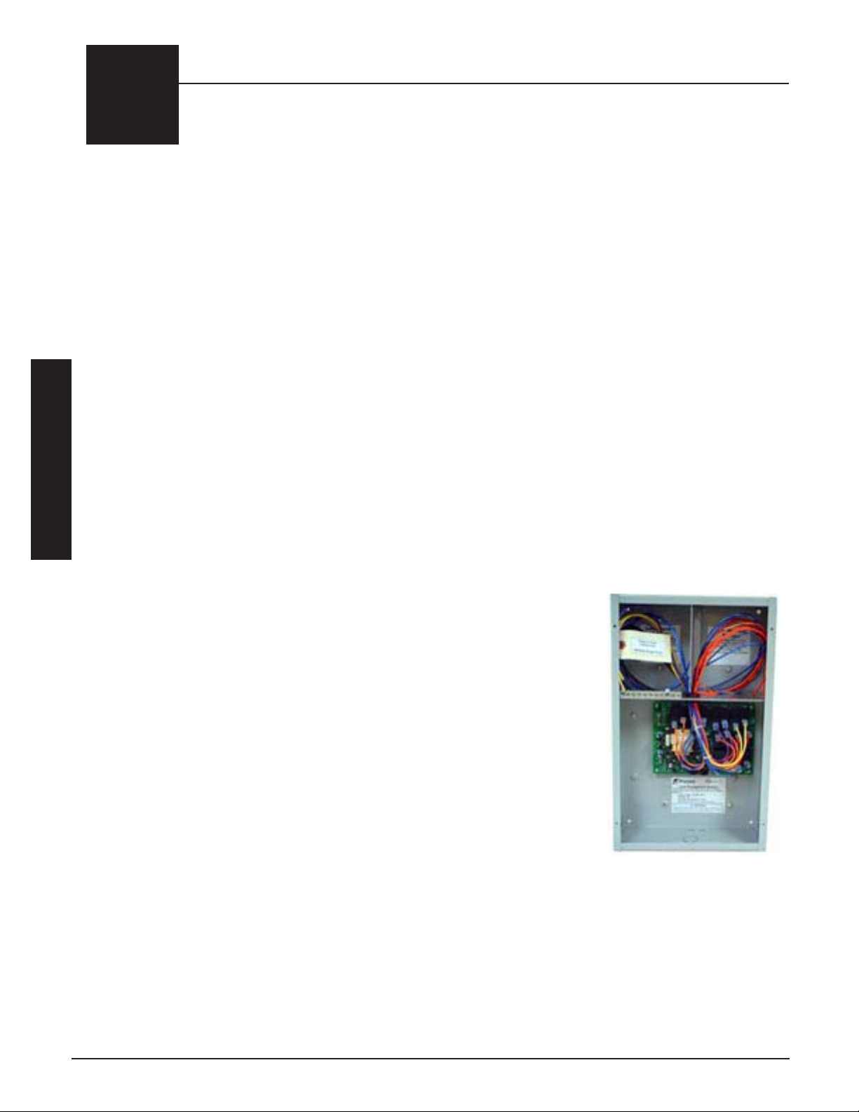
LOAD MANAGEMENT CONTROL
The ThermElect is a commercial Electric Thermal Storage (ETS) heating system. It uses Demand Free, Off-Peak
electricity to provide a low cost heating solution for commercial, industrial, and large residential applications. ETS
equipment is designed to store electricity, as heat, during hours when energy costs are lower and kW demand
charges are not incurred. The ThermElect’s thermal mass consists of a high-density ceramic brick capable of vast
heat storage.
The ThermElect system is designed to operate under one of three different load management control strategies.
1. On-Peak/Off-Peak Program
a) The ThermElect system responds to heat calls during the on-peak and off-peak periods; however, only
consumes energy (energize heating elements) during the off-peak periods. The ThermElect system is
controlled by an external control device such as a meter or time clock module.
b) The ThermElect system also offers on-peak control of external loads by utilizing the dry contacts provided
on the relay driver board.
2 . 4-20 Milliamp Control (1-5 volt DC)
a) The ThermElect system receives a signal from an external load control device such as a building load
Optional Accessories
management system. This external signal dictates to the ThermElect the maximum amount of energy
which can be consumed during a preset time interval.
b) Other external loads would generally be controlled through the building's
load management control system.
3. Pulse Monitoring
a) The ThermElect system monitors pulse outputs from the power company's
electric meter. Program parameters such as desired maximum building kW
and pulse ratios for the metering system being used are entered into the
ThermElect system. The system then changes proportionally when demand
free power is available. This keeps the total building kW usage at or below
the desired level.
b) External load management control modules (Order Item # 1908410) are
available when using pulse monitoring load control. Each module has eight
(8) zones which can be controlled. The ThermElect system must be
configured to recongnize the number of load management modules installed
(maximum of two per ThermElect system).
Reference the Load Management Section of this manual for more specific information on the individual methods
of control.
OPTIONAL ACCESSORIES 2.01 THERMELECT
Page 9
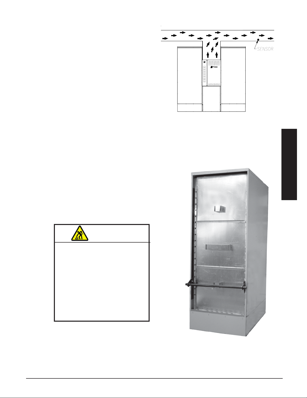
EXTERNAL DUCT SENSOR
The optional external duct sensor (Order Item #1041536)
provides the ability to monitor the duct temperature at an
area beyond fresh air makeup and/or beyond other
devices and regulate the discharge air temperature
accordingly.
The duct sensor feature is enabled if the 4 bit is set in
Location 53 (L053). Once enabled, the ThermElect
system monitors temperature at both the duct sensor and
the output sensor during Y, W, or E calls from the thermostat.
If there is a Y and a G call from the thermostat, the
ThermElect system operates the core blower at the
required speed to maintain the minimum output temperature as set in Location 48 (L048) at the duct sensor. If
there is only one call from Y, W, or E, then the system will operate the core blower at the required speed to
maintain the maximum output temperature as set in Location 49 (L049) at the duct sensor. The system is set to
turn off the core blower if the output temperature at the output sensor exceeds 150 degrees Fahrenheit.
LIFTING HANDLES
Optional lifting handles are available (Order Item #1302120) to aid in
moving the ThermElect Storage Module(s) into their final location. It is
extremely important to use caution when lifting a Storage Module.
Instruct workers to NOT walk under or place any body parts under
the Storage Module when lifting and/or moving.
W ARNING
HEAVY OBJECT WARNING: Risk
of personal injury, or death.
ThermElect Hydronic systems
are heavy. Use lifting aids to
move system into place.
Do not place object, hands,
and/or body parts under the
system when lifting.
Do use care to keep objects,
hands, and/or body parts clear
of system when lifting.
Optional Accessories
THERMELECT OPTIONAL ACCESSORIES 2.02
Page 10
3
Installation
SHIPPING AND PACKAGING
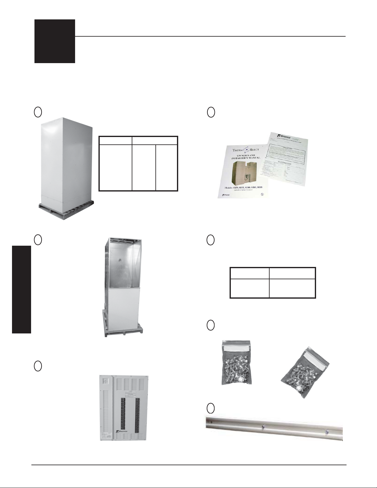
The ThermElect Storage Module(s) should always be transported in an upright position to avoid damage to internal
components and insulation materials. The information below describes the items shipped with each system.
STORAGE MODULE(S)
1
AIR HANDLER
2
2000 CFM - Standard
3000 CFM - Optional
(shipped separately)
MODULES
MODEL 53kW 80kW
8150 1 0
8155 2 0
8180 0 1
8185 1 1
8188 0 2
INFORMATION PACKAGE
4
(includes Owner's Manual and
Warranty Registration Card)
(included on pallet with the electrical panel )
HEATING ELEMENTS
5
WITH CERAMIC INSULATORS
MODULE ELEMENTS
53kW 12 (2 boxes of 6)
80kW 18 (3 boxes of 6)
(shipped separately)
Installation
ELEMENT SCREW KIT &
6
INSTALLATION HARDWARE KIT
(shipped
inside the
ELECTRICAL PANEL
3
(includes electrical
panel mounting
screws, romex
connectors, and
wiring schematic)
(shipped separately)
208/240V shown
INSTALLATION 3.01 THERMELECT
SEAM WRAP
7
(shipped inside brick storage cavity)
electrical
panel)
Page 11
SHIPPING AND PACKAGING CONTINUED...
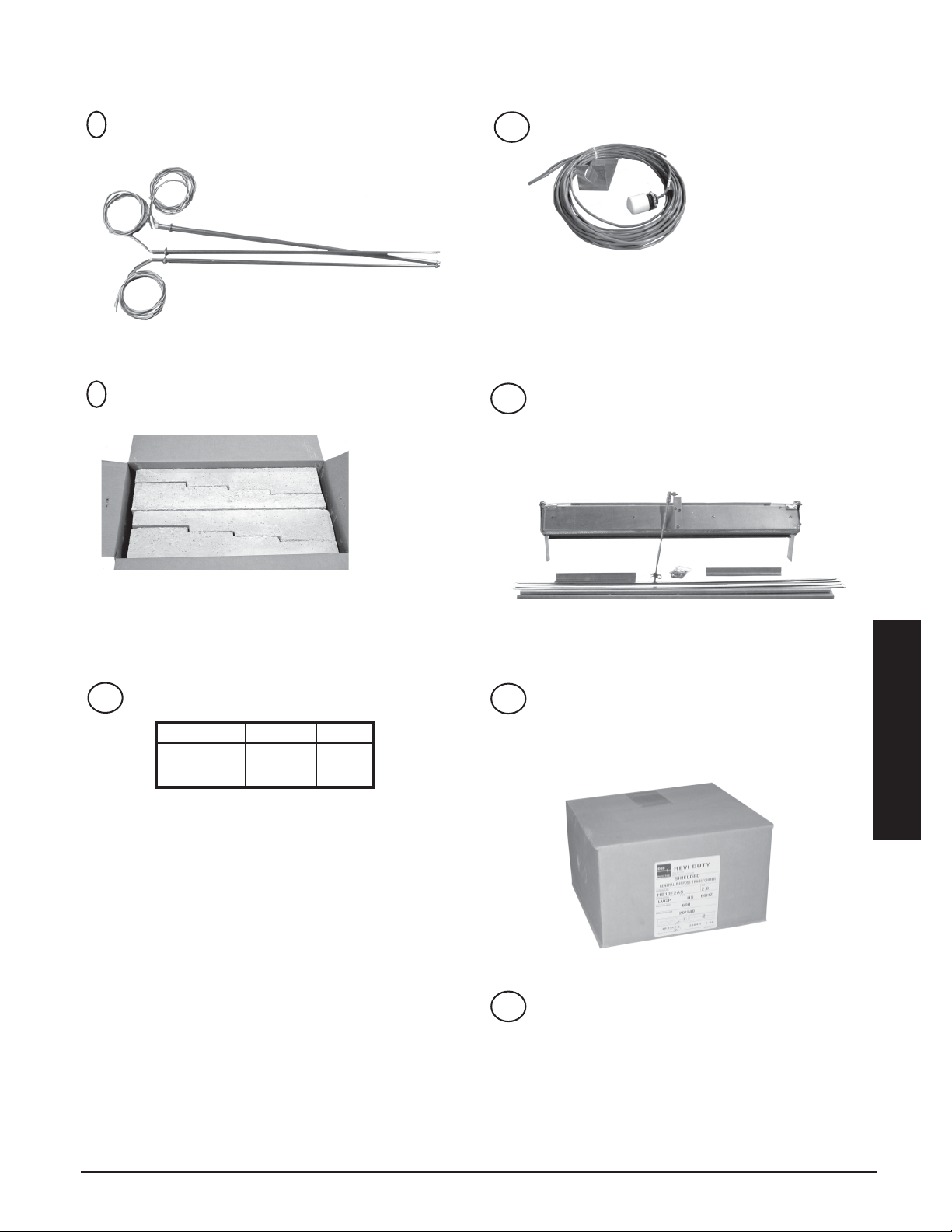
CORE THERMOCOUPLE
8
WITH 6' CLEAR PLASTIC TUBE
OUTDOOR TEMPERATURE SENSOR
11
53 kW = Qty 2 per module
80 kW = Qty 3 per module
(shipped inside the electrical panel)
9
TOP AIR CHANNEL BLOCK
1 box of 4 per Storage Module
(shipped separately)
(shipped inside the
electrical panel)
OUTLET DAMPER KIT
12
1 per Storage Module
(includes Damper Assembly, Damper Linkage, 2
- L Brackets, 2 - C Clip Drive Brackets,
2 - C Drives, Hardware Screw Kit)
(shipped separately)
10
CERAMIC BRICK
MODULE BRICK LBS
53kW 19 2 3,360
80kW 28 8 5,040
96 brick per pallet
(shipped separately)
HIGH VOLTAGE KIT
13
(277V & 347V SYSTEMS ONLY)
Sized for Air Handler
(includes fuses and transformers)
(shipped separately)
TRANSFORMER WIRING HARNESS
14
(277V & 347V SYSTEMS ONLY)
(shipped in electrical panel)
Installation
THERMELECT INSTALLATION 3.02
Page 12
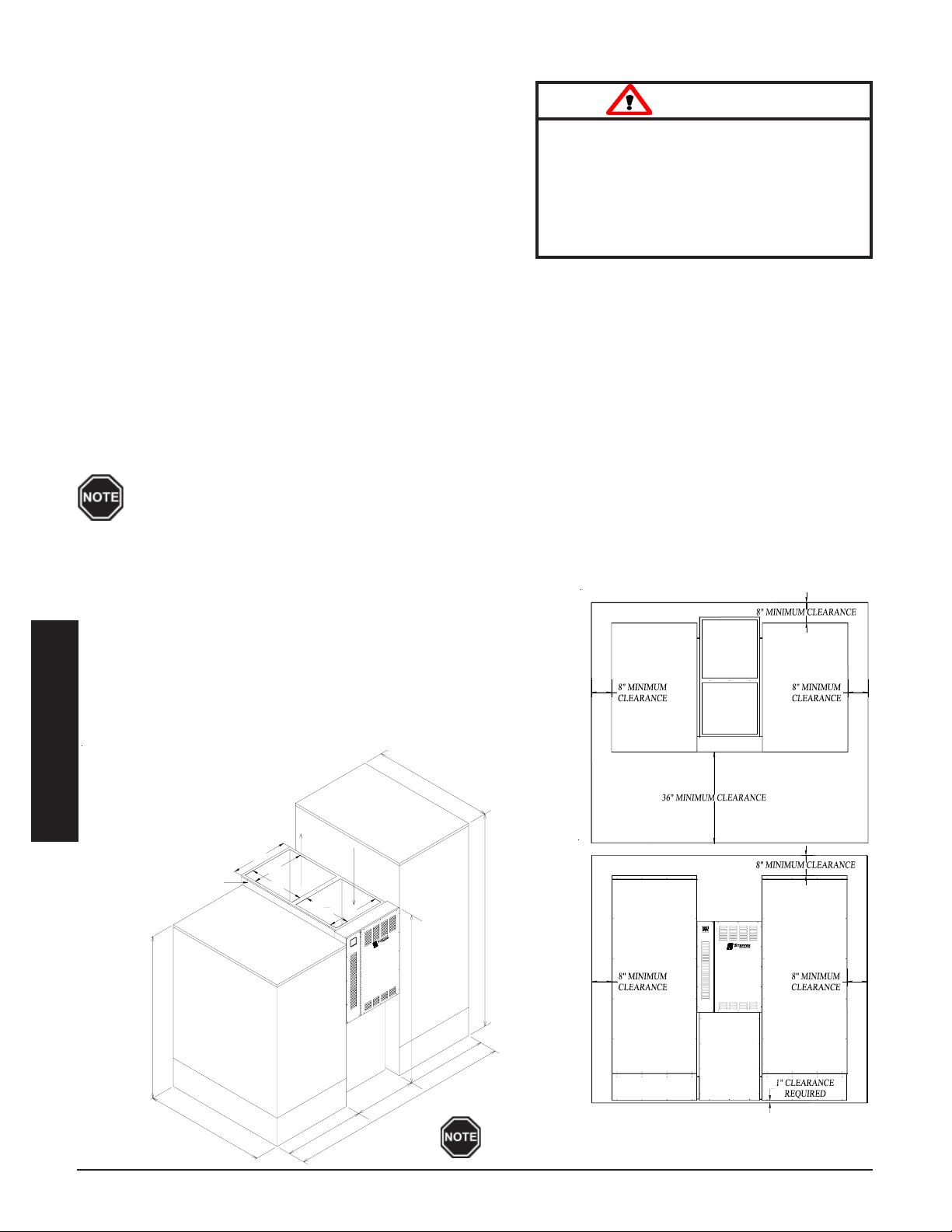
PLACEMENT AND CLEARANCE REQUIREMENTS
The system dimensions and required clearances MUST be taken
into consideration when choosing its location within a structure.
(See Figure 2 for dimensions and clearance requirements.)
The best installation location for the system is in a space requiring
heat so some amount of the heating requirements can be satisfied
through static dissipation from the warm outer panels of the
Storage Module(s). In situations where the system is not installed
in an area it is intended to heat (i.e. garage), it is important to
account for the heat lost through static dissipation by making
proper adjustments when sizing.
Risk of injury or fire. Violation of the
clearance requirements and/or failure to
provide proper ventilation can cause
improper operation of the system. Maintain the placement and clearance requirements as specified and provide ventilation
as necessary.
W ARNING
The minimum area required for the installation of the system is 100 square feet per Storage Module. This area
must remain free of debris and room air should be maintained at less than 85
o
Fahrenheit. Ventilation
MUST be provided if the system is being installed in an area with less than 600 square feet. It is the responsibility
of the installer and system designer to provide this ventilation.
In addition to the physical space requirements, the weight of the system must also be taken into consideration
when selecting the installation surface. A level concrete floor is the designed installation surface, but most well
supported surfaces are acceptable. If unsure of floor load capacity, consult a building contractor or architect.
Special requirements must be considered if placing the system in a garage or other area where
combustible vapors may be present. Consult local, state, and national codes and regulations to
ensure proper installation.
SYSTEM REQUIREMENTS
FIGURE 2
Storage Module (53kW and 80kW)
Back = 8 inches
Bottom = 1 inch (from combustible
material)
Sides = 8 inches
Top = 8 inches (from combustible
material)
Front = 36 inches (for ease in
servicing)
Air Handler (2000 and 3000 CFM)
Back = 1 inch clearance
Bottom = 1 inch (from combustible
material)
Sides = 1 inch clearance
Top = 0 inches (from combustible
material)
Front = 36 inches (for ease in
servicing)
CLEARANCES
5
1
Installation
m
M
a
n
DIMENSIONS
1
"
C
l
e
a
r
a
n
i
a
o
d
d
/
c
n
t
a
i
n
e
e
b
d
t
u
l
A
e
s
,
i
r
H
a
o
C
r
b
o
m
u
s
t
69"
e
e
w
d
n
i
b
m
u
s
t
e
b
e
t
S
n
o
r
g
a
l
n
i
g
y
s
t
S
e
l
M
e
t
a
r
e
i
a
5
1
"
24"
e
m
l
s
.
22"
23"
Supply
3
5
O
T
S
M
Return
13
19
"
16
22"
a
c
i
r
t
c
l
e
e
l
n
E
a
W
K
G
A
R
L
U
D
O
4
3
P
E
E
g
n
i
l
d
n
a
m
H
e
t
r
i
s
y
A
S
"
6
2
"
"
W
E
K
0
G
8
A
R
E
O
L
T
U
S
D
O
M
90"
l
71 1/8"
"
4
3
"
4
9
Some electrical codes may require a greater front clearance
depending on operating voltages and other factors.
INSTALLATION 3.03 THERMELECT
Page 13
INITIAL SET-UP
Step 1 Remove the Information Package from the outside of the
electrical panel and unpackage the Storage Module(s) and
Air Handler.
Step 2 Move the system into its installation location. Optional liftting
handles are available from the factory. (Order Item
#1302120).
If using Steffes lifting handles, remove
painted front and back panels from brick
storage cavity.
HEAVY OBJECT WARNING: Risk
of personal injury, or death.
ThermElect Hydronic systems
are heavy. Use lifting aids to
move system into place.
Do not place object, hands,
and/or body parts under the
system when lifting.
Do use care to keep objects,
hands, and/or body parts clear
of system when lifting.
W ARNING
CAUTION
Risk of improper operation or equipment damage. Read and follow installation instructions carefully.
DO NOT install the system on its shipping pallet.
DO NOT extend the leveling legs more than one inch.
DO use and follow generally accepted safety practices when handling insulation materials.
Equipment MUST be installed by qualified technician in accordance with all applicable codes and regulations.
ATTACHING STORAGE MODULE(S) TO AIR HANDLER
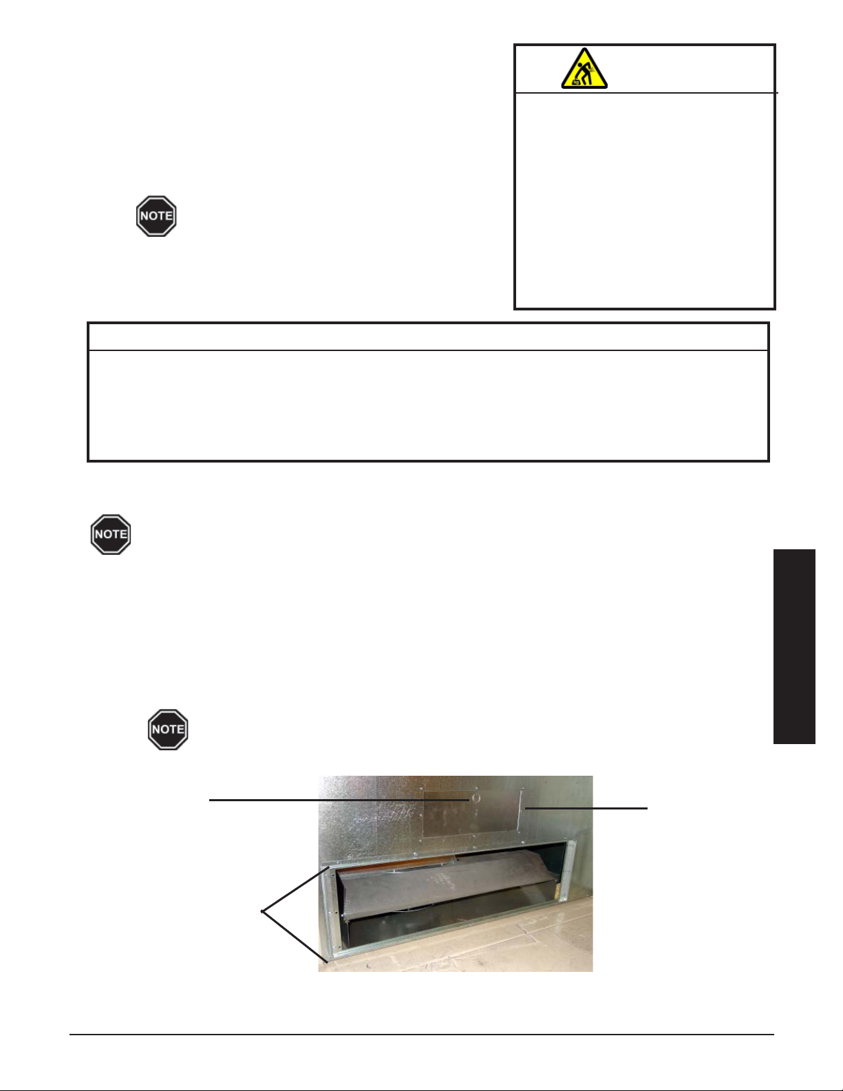
Each side of the Air Handler has a Storage Module Inlet/Outlet Opening, Limit Access Panel
and knockout. If using only one Storage Module follow the instructions below for the side of
the Air Handler where the Storage Module will be attached.
Step 1 Remove the screws around the Storage Module Inlet/Outlet Opening(s) on the side of the Air Handler
where the Storage Module will be placed. (See Figure 3.)
Step 2 Remove the front painted panel from the Air Handler and set aside.
Step 3 Lift the Storage Module Inlet/Outlet Opening cover(s) out through the front of the Air Handler.
Step 4 Attach the top and bottom C-clip drive brackets and the side L brackets to the Air Handler.
(See Figure 3.)
When attaching the top C-clip drive bracket, use the top row of screw holes.
FIGURE 3
Knockout
Storage Module
Inlet/Outlet Opening
(Cover Removed)
Limit Access
Panel
Installation
THERMELECT INSTALLATION 3.04
Page 14
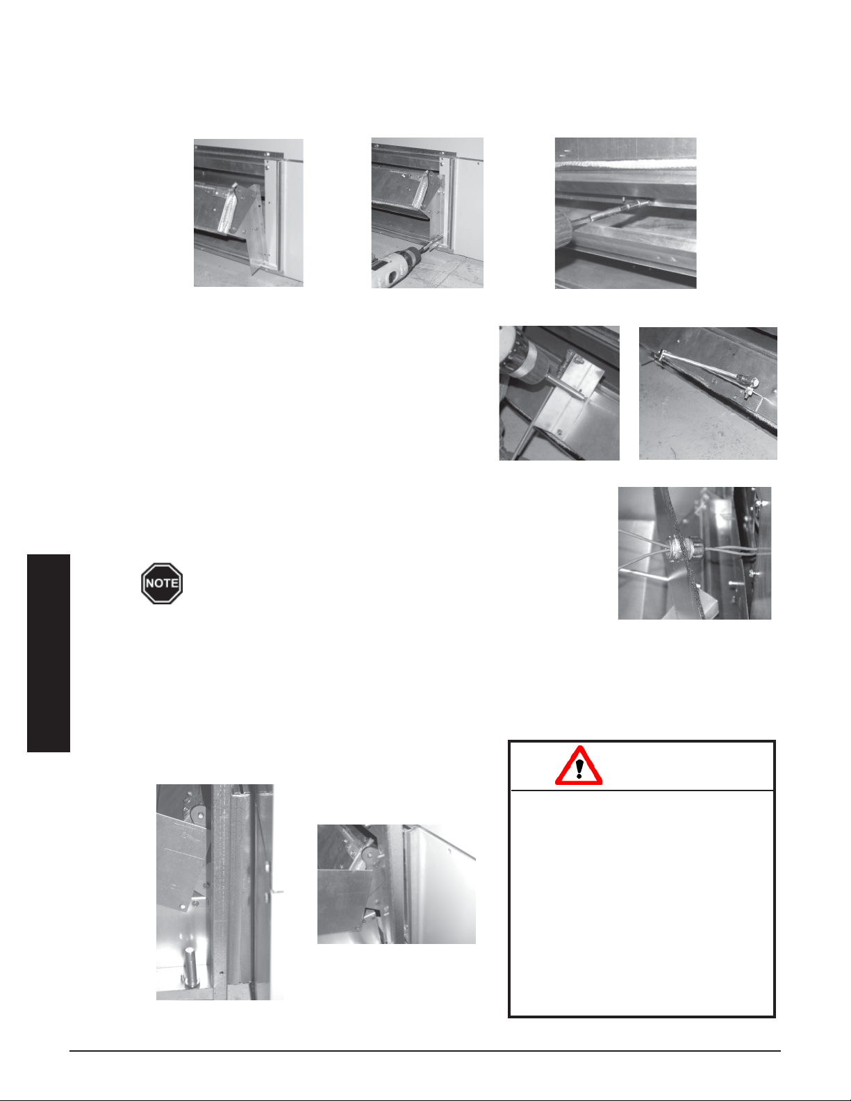
Step 5 Securely mount the damper(s) to the Storage Module(s) using the screws provided in the outlet damper
kit. Two screws are required for each side of the damper assembly (Figures 4A and 4B); four screws
are inserted along the top and four screws are inserted along the bottom of the damper. To insert the top
screws, open the damper as shown in Figure 4C.
FIGURE 4
A
B
C
Step 6 Remove the top two screws from the damper bracket
at the center of the damper assembly (Figure 5A).
FIGURE 5
A
Rotate the damper actuator assembly 90 degrees
(Figure 5B) to keep it out of the way when attaching
the Storage Module(s) to the Air Handler.
Step 7 Remove the 7/8" (inner) knockout on the limit access
panel (Figure 3) on the side(s) of the Air Handler
where the Storage Module(s) will be attached.
Step 8 Move the Storage Module(s) within 6" of final position to Air Handler. Once
FIGURE 6
in place, adjust the leveling legs on the bottom of the Storage Module(s) as
necessary to prevent rocking. If not placed properly the system may bend
or twist during the brick loading process, causing alignment problems during
re-assembly.
DO NOT extend the leveling legs more than 1".
Step 9 Locate the orange limit switch wires in the limit area of the Storage
Module(s). Secure the connector located on these limit switch wires into the knockout on the limit
access panel (Figure 6).
Step 10 Making certain that the orange limit switch wires between the Air Handler and Storage Module(s) are
Installation
routed properly, move the Storage Module(s) into their final location next to the Air Handler. The edge
of the side L brackets on the Air Handler MUST fit inside the S-Clip brackets on the side(s) of the
Storage Module(s). (See Figures 7 and 8.)
B
FIGURE 7
FIGURE 8
INSTALLATION 3.05 THERMELECT
Risk of Improper Operation and
Equipment Damage. Improper routing
of the limit switch wires can result in
improper operation or equipment damage. DO NOT physically damage or
route the limit switch wires near high
temperature areas. When attaching the
Storage Module to the Air Handler make
sure the limit switch wires are not
pinched or cut. When routing the limt
switch wires inside the Air Handler,
make sure they are routed through the
pre-installed plastic cable ties.
CAUTION
Page 15
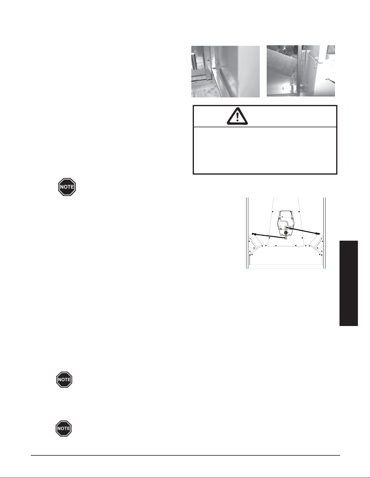
Step 11 Attach the Storage Module(s) to the Air Handler using the C-drives provided (Figure 9). Bend excess
length of drives over to seal the damper area (Figure 10).
Step 12 Route the orange limit switch wires through the
FIGURE 9
FIGURE 10
pre-installed plastic cable ties on the inside of
the Air Handler.
Step 13 Connect the orange limit switch wires from the
Storage Module(s) to the orange wires from the
electrical panel. When installing dual Storage
Modules it is important to connect the wires
from the left side of the electrical panel to the
left Storage Module and the wires from the
right side of the electrical panel to the right
W ARNING
Storage Module.
Step 14 Secure the damper actuator linkage(s) to the
damper actuator arm(s) inserting the supplied
spring clips through the hole in the pivot connector. The top hole in the actuator arm MUST be
used for the right side damper. (See Figure 11.)
Risk of fire and/or equipment damage. When
installing dual Storage Modules it is important
to connect the orange/black wires from the left
side of the electrical panel to the left Storage
Module and the right side wires to the right
Storage Module.
The upper pivot hole on the actuator arm is for the
right side Storage Module. The lower pivot hole on
the actuator arm is for the left side Storage Module.
AIR HANDLER
DAMPER LINKAGE
FIGURE 11
Step 15 Adjust damper linkage length(s) appropriately to ensure the
damper(s) fully close. Check the ball end linkage connector on the
damper. The nut side MUST be facing the front of the system. If
not, it MUST be inverted.
Step 16 With the system de-energized, adjust the linkage by rotating the
quick disconnect end of the linkage until the damper is pressed
firmly in the closed position.
ELECTRICAL PANEL INSTALLATION
Step 1 Reinstall the painted front panel on the Air Handler to aid in installation of the electrical panel.
Step 2 Remove the electrical panel front cover and locate the installation hardware package.
Step 3 Remove 1/2" knockout and 1" knockout from sides of electrical panel and Storage Module(s) to allow
connection. DO NOT remove any uneeded knockouts.
Step 4 Lift the electrical panel onto the support bend of the Air Handler's painted front panel.
Step 5 Secure the electrical panel to the Air Handler with the five 8 x 3/4" sheet metal screws shipped with
the outlet damper kit.
Step 6 Remove the lower painted front panel of the Air Handler.
Step 7 Connect the 9-pin blower harness from the Air Handler to the harness from the electrical panel.
Installation
Knockout must be effectively sealed by connector.
Step 8 277/347 only. Remove one 1/2" knockout from lower left hand bottom panel and connect straight seal-
tite connector on conduit to bottom of electrical panel. Connect the other end of the conduit to dry type
enclosed transformer. Mount the transformer to the Air Handler's painted front panel. Make connec-
tions according to instructions with transformer.
Install only the proper size and type fuses in the factory supplied fuse block.
THERMELECT INSTALLATION 3.06
Page 16
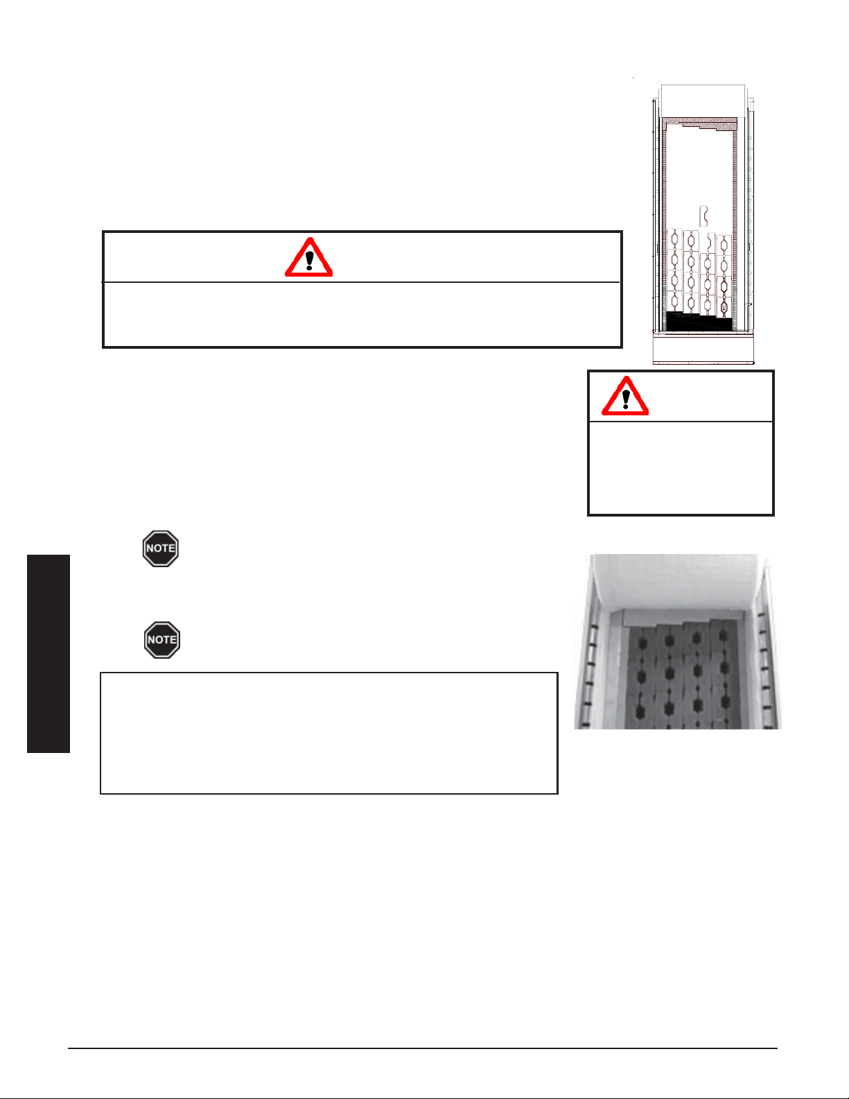
BRICK LOADING
Step 1 Remove the painted front panel of the brick Storage Module(s) by removing
the sheet metal screws along the top, bottom, and sides of the panel. Detach
by pulling the bottom of the panel forward and down.
Step 2 Remove the sheet metal screws around the outer edge of the galvanized front
panel. Remove the panel and set it aside.
Step 3 Starting at the bottom, carefully lift each of the insulation blankets and drape
them over the top of the Storage Module(s).
CAUTION
Risk of equipment damage or personal injury. Insulation boards located behind
the insulation blankets may fall out when blankets are lifted. Use caution when lifting
insulation blankets to avoid personal injury or damage to the insulation boards.
Step 4 Remove the rigid insulation boards and place to the side in the order
removed.
Step 5 Load the brick, one row at a time, starting at the back of the brick
core and working forward. Load bricks as shown in Figure 12. Make
certain brick debris does not interfere with brick alignment front to
back.
Step 6 Install top air channel block by sliding it up and back into place on top
of the bricks. (See Figure 13)
Risk of injury or fire. DO
NOT operate the system if
damage to the insulation
panels on the inner sides
of the brick core occurs.
BRICK LOADING
FIGURE 12
W ARNING
For ease of installation, install top block while loading
bricks.
Step 7 Install rigid insulation boards into the Storage Module(s) in the order
they were removed in Step 4.
The holes in the rigid insulation board MUST line up
with the brick openings so elements can be installed.
Installation
BRICK INSTALLATION TIPS:
• Install bricks carefully to avoid damage to the insulation panels.
• Remove loose brick debris to prevent uneven stacking of brick
as this can make installation of the elements and the brick core
temperature sensor(s) difficult.
• Brick rows MUST line up front to back and top to bottom.
FIGURE 13
INSTALLATION 3.07 THERMELECT
Page 17
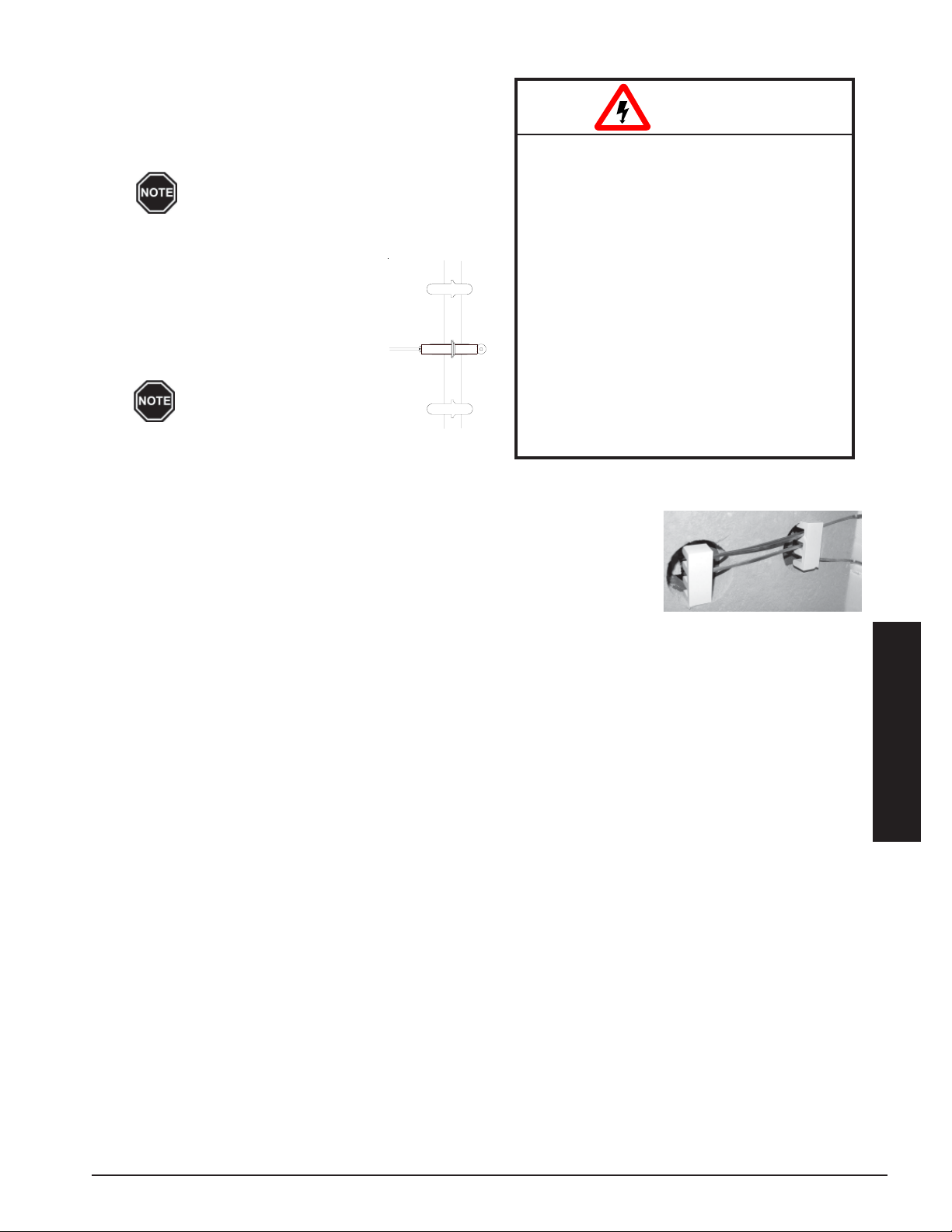
HEATING ELEMENT INSTALLATION
Step 1 After all bricks are loaded and rigid insulation boards
are in place, insert the heating elements through the
insulation, sliding them in until the cement side rails
HAZARDOUS VOLT AGE: Risk of electric
are flush with the front side of the ceramic brick.
Make sure the elements designated as
Air Handler side elements are installed
on the Air Handler side of the Storage
Module(s).
FIGURE 14
Step 2 Route the element termination head
with ceramic insulator to the appropriate side of the Storage Module(s).
Insert the lead into position as
shown in Figure 14.
Element leads must never
cross each other.
Step 3 Install element lead insulators. These ceramic
insulators MUST maintain lead wire spacings as
shown in Figure 15.
Step 4 Lower the insulation blankets back into position, one at a time. Carefully
tuck the sides of the insulation into the edges, corners, and around the
exposed portions of the heating element to ensure maximum efficiency.
shock, injury , or death.
DO NOT remove the electrical panel
cover while system is energized.
Elements MUST be positioned prop-
erly to avoid short circuiting against
any surfaces within the system.
Risk of improper operation or equipment
damage. On Dual Storage Module
systems, it is critical to route the correct
harness to each of the Storage Modules.
Mis-routing of harness will result in
improper operation and equipment
damage. Make certain the harness
connected to the right side relay bank in
the electrical panel is routed to the right
side Storage Module.
W ARNING
FIGURE 15
Step 5 Reinstall the galvanized front panel and secure it to the system using the
screws originally removed.
Step 6 Route element harnesses through connectors, using one connector/harness until tape is centered in
connector. If installing two Storage Modules, use left hand bank of relays for left hand and right hand for
right hand. One harness per module is shorter and must be used for inside element connections.
Step 7 Attach element lead wires to element terminals. Start at the top using the appropriate color chart below.
Repeat pattern as necessary.
277/347V = Black (Top) 208/240V = Black (Top) 240V = Black (Top)
Systems White 3phase Red 1phase Red
Red Systems Blue Systems Black
White Black Red
Blue Red
White Blue
Installation
THERMELECT INSTALLATION 3.08
Page 18
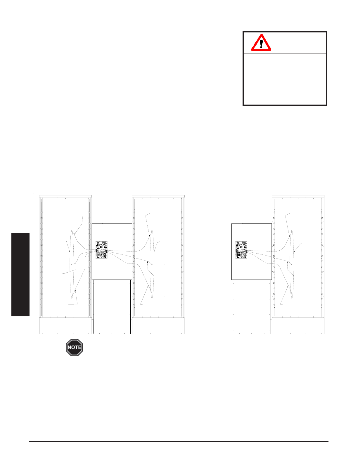
BRICK CORE TEMPERATURE SENSOR INSTALLATION
Step 1 Remove the screw(s) by the brick core temperature sensor connector
holes in the galvanized front panel.
Step 2 Route the brick core temperature sensors through the clear plastic
tube until within six inches of the relay driver board. Cut tube and
sensor wires to length as needed. The yellow wire from each sensor
must be connected to the Y terminal of the proper sensor connection
terminal block, and red to R. Polarity of sensors is critical.
Sensor connections MUST be installed as follows:
• Single Module - 8150 or 8180 (Figure 16)
• Bottom sensor to core C
• Second sensor to core D
• Third (if equipped) to core E
• Dual Module - 8155, 8185, and 8188 (Figure 16)
• Left module • Right module
• Bottom sensor to core F • Bottom sensor to core C
• Second sensor to core G • Second sensor to core D
• Third (if equipped) to core H • Third (if equipped) to core E
CORE TEMPERATURE SENSOR CONNECTIONS
FIGURE 16
Models: 8155 & 8188
Risk of improper operation.
Proper installation of the brick
core temperature sensor is
critical to the operation of the
heating system. Read and
follow installation instructions
carefully.
CAUTION
Models: 8150 & 8180
Connect To Core "E"
80 Kw Module Only
Connect To
Connect To Core "H"
80 Kw Module Only
Core
Temperature
Sensors
Connect To
Core "G"
Relay
Driver
Board
Connect To Core "E"
80 Kw Module Only
Core
Temperature
Sensors
Connect To
Core "D"
Relay
Driver
Board
Installation
Connect To
Core "F"
In systems using both an 80kW and 53kW Storage Module, the 53kW Storage Module must be
installed on the left side of the Air Handler.
Connect To
Core "C"
Connect To
Core "C"
Step 3 Insert the brick core temperature sensors through the holes in the galvanized front panel. The sensors
must pass through the blanket and board insulation and into the brick core. Use the sensors to aid in
making a passageway by rotating the sensors while gently pushing inward.
Core
Temperature
Sensors
Core "D"
Step 4 Once brick core sensors are installed, re-install sensor mounting screws to secure and ground the sensors.
Step 5 Re-install the painted front panel, using previously removed screws.
INSTALLATION 3.09 THERMELECT
Page 19
AIR CONDITIONER/HEAT PUMP INTERFACE
The system can accommodate most heat pump or air conditioner indoor
coils up to a 7.5-ton capacity provided the heat pump or air conditioner is
W ARNING
sized in accordance to supply air delivery rates of the system. Refer to the
System Air Delivery Matrix for information on air delivery rates of the
supply air blower with regard to the blower’s speed, To ensure that adequate air flow is provided for the heat pump or air conditioner system
being installed.
When interfacing the system with a heat pump, the indoor coil MUST be
placed on the return side of the system in a position that provides even air
flow through the coil. The installer needs to make provisions in the plenum
to accommodate the coil and air filter.
When interfacing with an air condi-
tioner, the indoor coil can be placed on either the supply air or return air
side. The condensate drain trap, in a heat pump or air conditioner installa-
Risk of fire. Any one ducting
system MUST NOT contain more
than one air handling (blower)
system. If the application
requires multiple systems or it is
necessary to have multiple air
handlers share the same
ductwork, you MUST contact
Steffes Corporation. There are
special installation requirements that MUST be performed.
tion, should be designed for the vacuum in which the system is operating. Typically, taller traps are better suited
for these types of applications.
Refer to the Room Thermostat Connections Diagrams for more information on interfacing the system with a
heat pump or air conditioner. Refer to Location 46 and 47 in the Supplemental Installer's Guide for information
on compressor control from the ThermElect system using outdoor temperature lockout.
DUCTING
SUPPLY AIR BLOWER SPEED
For air delivery, the system is equipped with a 2000 CFM Air
Handler containing a 3-speed supply air blower. The system is
factory wired to operate in medium speed for “heating” and in
high speed for “cooling” or a “fan only” thermostat setting.
Blower speed selection is made at the supply air blower. To
change blower speed for either "heating" or "cooling" modes,
detach the quick disconnect terminals at the supply air blower.
Select the blower speed and connect the corresponding wires.
When interfacing the system with a heat pump,
the blower speed connected to the high speed
relay is used for both heating and cooling.
HAZARDOUS VOLTAGE: Risk of
electric shock, injury or death. DO
NOT operate the system without
ducting installed to both the air
inlet and outlet.
EQUIPMENT DAMAGE: Risk of
equipment damage or improper
operation. On 3000 CFM systems
where there are multiple supply air
blowers, both blowers MUST be
connected to the same blower
speed to avoid equipment damage.
W ARNING
Installation
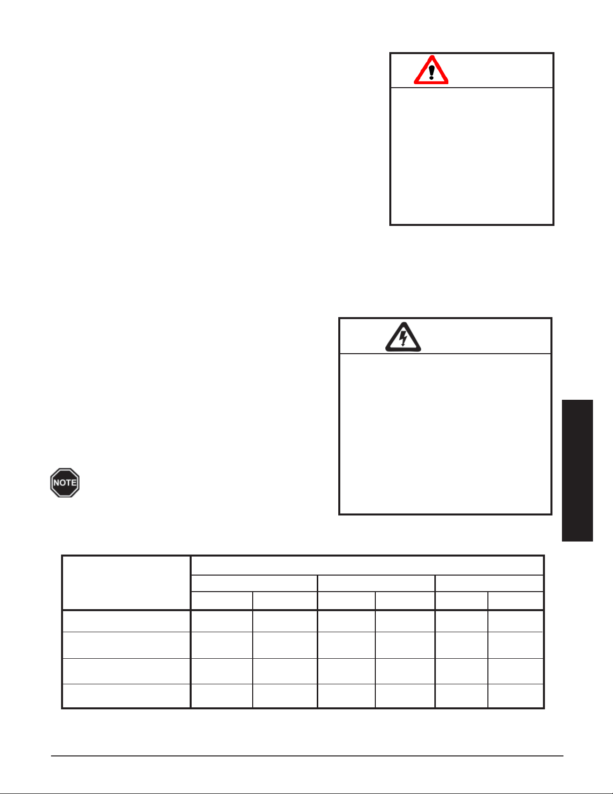
SYSTEM AIR DELIVERY MATRIX
(External static pressure should not exceed .75 inches water column for all models)
Supply Air
Blower Speed
.25" .50" .75"
2000 3000* 2000 3000* 2000 3000*
High (CFM) 2050 2950 1900 2490 1540 2160
Medium High (CFM) 1990 2850 1890 2350 1535 1980
Medium Low (CFM) 1870 2520 1670 2270 1450 N/A
Low (CFM) N/A 1920 N/A N/A N/A N/A
*An optional 3000 CFM Air Handler is available. The 3000 CFM Air Handler is equipped with two 4-speed
supply air blowers.
THERMELECT INSTALLATION 3.10
Page 20
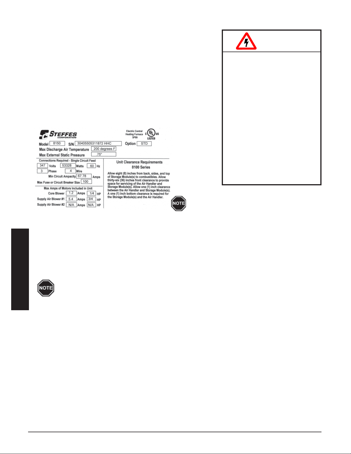
LINE VOLTAGE ELECTRICAL CONNECTIONS
To determine the correct wire size required for the circuit feeding the
system, refer to the Specifications (Page A.01-A.03) and the system's
identification label located on the front of the electrical panel (Figure 17).
HAZARDOUS VOLT AGE: Risk of
Step 1 Remove the electrical panel cover.
Step 2 Route all line voltage wires through a knockout and into the
electrical panel.
Step 3 Make line voltage connections (See Page 3.10) to lugs of single
feed bus and ground lug. Refer to the Line Voltage Wiring
Diagrams (Pages A.04 - A.05) for more information on these
connections.
SAMPLE SYSTEM IDENTIFICATION LABEL
FIGURE 17
W ARNING
electric shock, injury or death.
Do not energize the system
until installation is complete.
Equipment MUST be installed
by a qualified technician in
accordance with all applicable
local, state, and national codes
and regulations.
Risk of equipment damage,
personal injury or fire. Do NOT
install any wiring in line
voltage compartment unless
rated for line voltage. To
ensure proper operation and
safety, all wiring in the line
voltage compartment MUST be
rated for line voltage.
Use copper or aluminum conductors rated at
75oC or higher for line voltage field connection
of this device.
OUTDOOR TEMPERATURE SENSOR INSTALLATION
An outdoor temperature sensor, shipped in the electrical compartment, is required to be installed with the system.
This sensor monitors outdoor temperature and provides this information to the system. The system responds by
automatically storing heat in its brick core(s) according to the outdoor temperature and the heating requirements.
The outdoor temperature sensor can be installed in one of two ways: direct wired to the system or wired to the
Steffes power line carrier system. All 208/240V systems are factory configured for automatic charge
control with a direct wired outdoor sensor.
If connecting to the Steffes power line carrier (PLC) system, follow the installation instruc-
Installation
INSTALLING THE OUTDOOR SENSOR
Step 1 The outdoor sensor must be placed in a location where it can accurately sense outdoor temperature
Step 2 Route low voltage wire from the outdoor sensor to the electrical compartment through one of the low
tions in the PLC system's Owner's and Installer's Guide.
Outdoor sensor wire MUST NEVER be combined with other control wiring in a multi-
conductor cable.
and is not affected by direct sunlight or other abnormal temperature conditions. Select a location and
mount the sensor.
voltage wire knockouts.
• If the sensor wiring is routed through an external wall, the opening through which the wire
is routed MUST be sealed. Failure to do so may affect the accuracy of the outdoor
temperature sensor.
• The outdoor sensor is supplied with a lead length of 40 ft. If a greater wire length is
needed, it can be extended to a total of 250 ft. No other loads can be controlled or supplied through this cable. It is for connection of the outdoor sensor ONLY. This low voltage
cable should not enter any line voltage enclosure.
• Unshielded Class II (thermostat) wire can be used as extension wire provided it is segre-
gated from any line voltage cabling.
INSTALLATION 3.11 THERMELECT
Page 21
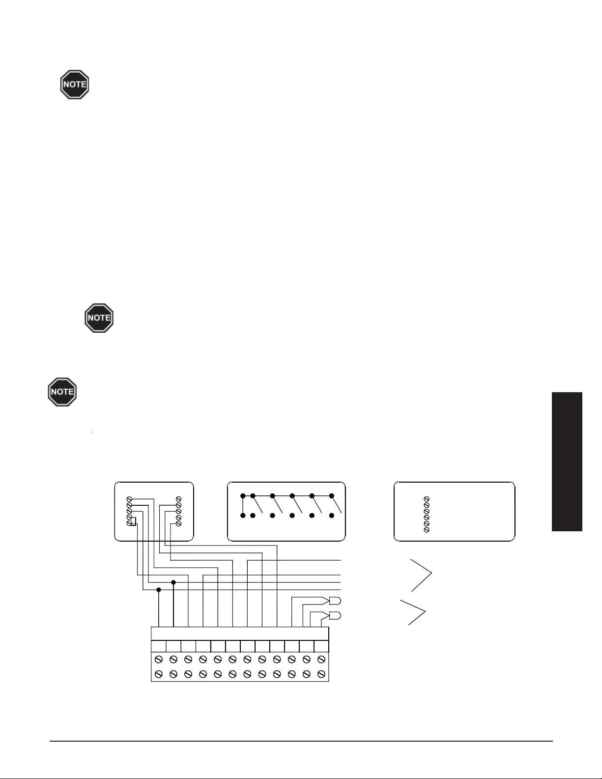
Step 3 Connect the outdoor sensor wires to the “OS” and “SC” positions of the twelve (12) position low
voltage terminal block located inside the electrical compartment.
Refer to Location 10 (L010) of the Supplemental Installer's Guide to select the desired
method of charge control.
THERMOSTAT CONNECTIONS
A low voltage room thermostat is required for room temperature control with the system. Any room thermostat
used with this system must be 24 VAC. (Contact the factory for more information on the thermostats available
from Steffes.)
INSTALLING THE THERMOSTAT
Step 1 Disconnect power to the system and route low voltage wire between the thermostat and the system.
Step 2 Insulate the wall opening through which the thermostat wires run. Failure to do so may affect the accu-
racy of the thermostat.
Step 3 Attach the thermostat to a wall. If installing a mechanical thermostat or thermostat with anticipator, a
resistor kit is required (Order Item #1190015).
Step 4 Route the low voltage wire into the electrical compartment of the system through one of its low voltage
wire knockouts and to the system's twelve (12) position low voltage terminal block.
Never install any wiring in the line voltage compartment of the system unless it is rated
for line voltage.
Step 5 Refer to the Room Thermostat Connections Diagrams (Figures 18 and 19) in this manual for proper
connections with regard to the application.
Refer to Temperature Control in the Operation Section of this manual for specific operation
information.
THERMOSTAT CONNECTIONS (Heat Pump Applications)
FIGURE 18
A Two Stage Heating and
Single Stage Cooling
Heat Pump Room Thermostat
Honeywell T8411R1028
W1
G
C
R
Y
L
W2
E
B
O
Terminals for Connection with Heat Pump
Y
CR
Y2
Thermostat Switches
G
YR
W
OO2 RSSCOS
EG
OW2 E
Typical Heat Pump Terminations
O (Reversing Valve)
Y (Compressor)
C (Low Voltage Common)
R (Low Voltage Hot)
Outdoor Sensor
Optional Freeze Protection
Room Sensor
C - To C on ThermElect
Y - To Y2 on ThermElect
O - To O2 on ThermElect
W2 - Not Used
R - To R on ThermElect
E - Not Used
Heat Pump
Connections
Temperature
Sensor Connections
Installation
12 Position Terminal Block
THERMELECT INSTALLATION 3.12
Page 22
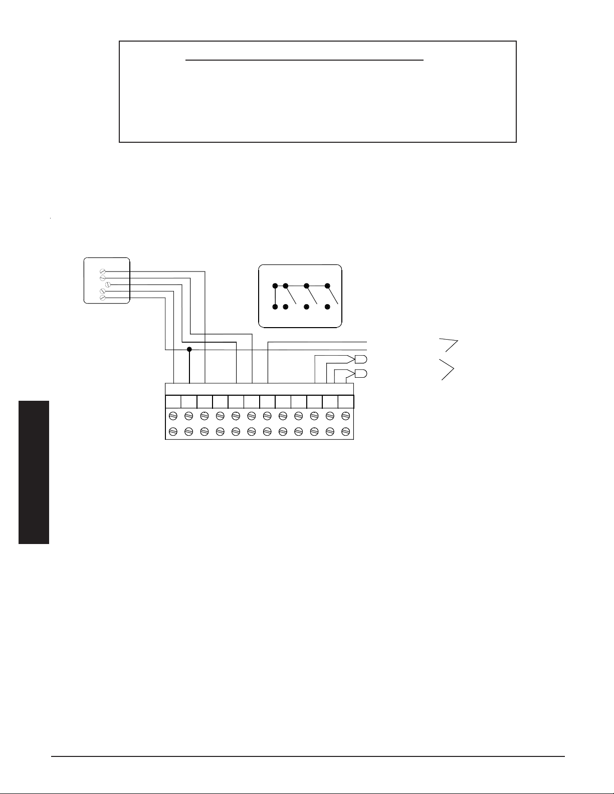
12-Position Low Voltage Terminal Block Coding
R = Low Voltage Hot
C = Low Voltage Common
Y = Compressor/Stage 1 Heat Call
W = Stage 2 Heat Call
Y2 = Compressor Output
G = Fan Call
THERMOSTAT CONNECTIONS (Stand Alone Furnace Application)
A Single Stage Heating
and Cool Room Thermostat
Honeywell T8401C1015
W
Y
G
R
C
O = Reversing Valve Input
O2 = Reversing Valve Output
E = Emergency Heat
OS = Outdoor Temperature Sensor
SC = Outdoor Temperature Sensor Common
RS = Freeze Protection Room Temperature Sensor
FIGURE 19
Thermostat Switches
WGYR
Terminals for Connection as a Stand Alone Furnace
R C
W
Y
G
Y2
W2
SCOS
RS
Y (Compressor)
C (Low Voltage Common)
Outdoor Sensor
Optional Freeze Protection
Room Sensor
Air Conditioner Connections
(If being used in the application)
Temperature
Sensor Connections
12 Position Terminal Block
Installation
ELECTRONIC AIR FILTER INSTALLATION
The ThermElect system is capable of being connected to an electronic air filter. Connections to the ThermElect
system are made to the bottom left relay (FAN ON) on the Base IO Relay Board inside the system's electrical
panel. This relay closes during a fan call. Refer to the Line Voltage Wiring Diagrams (Page A.04-A.05) for the
location of this relay.
INSTALLATION 3.13 THERMELECT
Page 23
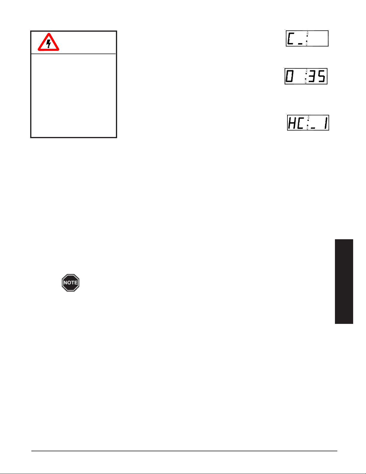
INSTALLER'S FINAL CHECK-OUT PROCEDURE
Step 1 Verify that the operating mode displayed on the
W ARNING
HAZARDOUS VOLTAGE:
Risk of electric shock,
injury, or death. System
may be connected to
more than one branch
circuit. Disconnect
power to all circuits
before servicing. Equipment must be serviced
by a qualified technician.
Step 4 Initiate a heat call from the room thermostat and verify that the system recognizes the heat call. Refer
to the Operating Status section (Page 1.02) for more information on the various heat call status displays.
The supply air blower should operate. In an application interfacing the system with an air conditioner or
heat pump, verify that this device is operating appropriately.
Step 5 Initiate a cooling call from the room thermostat, if applicable, and verify that the system recognizes the
“COOL” call. The supply air blower should operate. In an application interfacing the system with an air
conditioner or heat pump, verify that this device is operating appropriately.
Step 2 Press the up arrow one time and verify that the
Step 3 Press the up arrow again and the current heat call
control panel corresponds with the power
company's peak control signal. Refer to the Operating Status section (Page 1.02) for more information on the proper
operating mode.
outdoor temperature information displayed on the
control panel is approximately the same as the current outdoor
temperature. Refer to the Operating Status section (Page 1.02) for
more information on the outdoor temperature display.
status will be displayed on the control panel. Refer
to the Operating Status section (Page 1.02) for
more information on the heat call status display.
Step 6 Press the up arrow until the targeted brick core charge level is displayed on the control panel. With the
system in an off-peak (charge) mode, initiate a charge control override. (See Page 1.03.) Once initiated, the target level of the system should be 100 percent and the control panel should display “tL: F”.
All of the elements should be energized.
Step 7 With all heating elements operating, disconnect the orange/black wire located at the air outlet, above the
damper assembly of each Storage Module. When this wire is disconnected, all heating elements of that
Storage Module should turn off. Repeat this step on the second Storage Module (if equipped).
Ensuring that all heating elements turn off when the core limit(s) open is important.
Make sure Step 7 of the Installer’s Final Check-Out Procedure is completed.
Step 8 With an amp meter, verify that the amperage of the system is correct for the installation. Refer to the
System Identification Label on the heating system for information regarding the proper amperage.
Step 9 Cancel the charge control override and verify that all elements in the system de-energize. Refer to the
Charge Control Override section (Page 1.03) for instructions on canceling the charge control override.
Step 10 Verify, once again, that the Operating Mode displayed on the control panel corresponds with the power
company's peak control signal.
Step 11 In applications utilizing the Steffes Power Line Carrier control system, complete the Installer’s Final
Check-Out Procedure in the Owner’s and Installer’s Manual provided with that device.
Step 12 Complete the manufacturer's warranty card and return promptly.
Installation
THERMELECT INSTALLATION 3.14
Page 24
4
The ThermElect is a commercial Electric Thermal Storage (ETS) heating system. It is generally signaled to use
demand free, off-peak electricity to provide a low cost heating solution for commercial, industrial, and large residential
applications. ETS equipment is designed to store electricity , as heat, during hours when energy costs are lower and
kW demand charges are not incurred. The ThermElect’s thermal mass consists of a high-density ceramic brick
capable of vast heat storage.
The ThermElect system is designed to operate under one of three different load management control strategies.
LOAD MANAGEMENT
ON-PEAK/OFF-PEAK PROGRAM
The ThermElect system responds to heat calls during the on-peak and off-peak periods; however, only consumes
energy (energize heating elements) during the off-peak periods. The ThermElect system is controlled by an
external control device such as a meter or time clock module and also offers on-peak control of external loads by
utilizing the dry contacts provided on the relay driver board.
Never install any wiring in a line voltage compartment of the system unless it is rated for line
voltage.
The ThermElect system may be controlled by the Power Company via a peak control signal. This signal can be
sent to the equipment using low voltage wiring, a Steffes Time Clock Module, or a Steffes Power Line Carrier
control system (208 and 240V applications only). In applications utilizing automatic charge control, outdoor
temperature information is required and can be received via an outdoor sensor or power line carrier control
system.
The heating system is factory configured for low voltage wire control and is set to charge when the utility peak
control switch closes.
LOW VOLTAGE (DIRECT WIRED) PEAK CONTROL
If using the low voltage peak control option, the system is direct
wired to the power company's peak control switch. Field connections from the peak control switch are made to the low voltage
terminal block through a low voltage knockout located on the left
side of electrical panel.
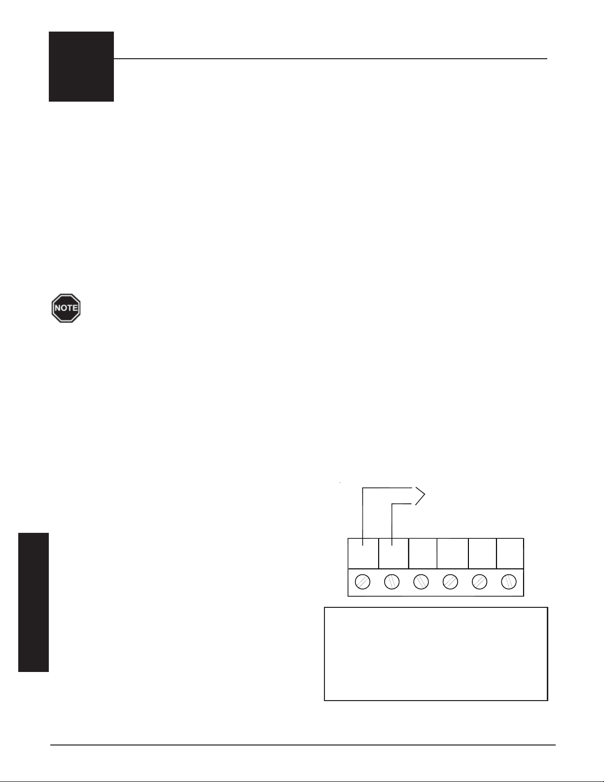
Step 1 Route a low voltage circuit from the power company’s
load control or peak signaling device to the six (6)
position terminal block (Figure 20) inside the electrical
compartment.
Step 2 Connect the field wiring to positions "RP" and "P" on
the six (6) position low voltage terminal block. (See
Figure 20.)
Load Management
PEAK CONTROL TERMINAL
CONNECTIONS
FIGURE 20
Dry Contact Peak
Control Switch
AP
RP
6-Position Low Voltage Terminal Block Coding
R P = Peak Control Input Common
P = Peak Control Input
AP = Anticipated Peak (Pre-Peak) Control Input
CO M = Peak Control Output Common
N C = Peak Control Output (Normally Closed)
N O = Peak Control Output (Normally Open)
COM
NCP
NO
LOAD MANAGEMENT 4.01 THERMELECT
Page 25
TIME CLOCK MODULE PEAK CONTROL
The Steffes Time Clock Module is another option for providing a peak control signal to the system. The optional
time clock module mounts inside the line voltage electrical compartment and interfaces with the relay board via an
interface cable. Peak control times MUST be programmed into the system once the module is installed to enable
the time clock feature. Refer to the instructions provided with the time clock module for more information on the
installation and operation of this device.
POWER LINE CARRIER (PLC) PEAK CONTROL
Power Line Carrier (PLC) control is only available in 208/240V applications.
The Steffes Power Line Carrier (PLC) control system has the ability to communicate with the system through the
existing electrical circuits in the structure. With the power line carrier option, direct wired low voltage connections
from the power company's peak signaling switch connect directly to the transmitting device. The switch signals
peak control times to the transmitter, the transmitter sends the signals to the system, which receives this information and responds accordingly.
In addition to providing peak control signals, the transmitter also provides outdoor temperature information for
automatic charge control, room temperature set back, and anticipated peak utility control signals (if applicable).
The PLC system is optional and must be ordered separately. If utilizing a PLC system, an Owner's and Installer's
manual will accompany the transmitting device. Refer to this manual for information on the installation and
operation of the power line carrier control system.
4-20 MILLIAMP CONTROL (1-5 VOLT DC)
The ThermElect system receives a signal from an external load
control device such as a building load management system. This
external signal dictates to the ThermElect the maximum amount of
energy which can be consumed during a preset time interval. This
value is recalculated automatically every 15 minutes.
To enable the 4-20 milliamp control, the one (1) bit must be added to
the current value of Location 53 (L053). Once enabled, the
ThermElect system will continually monitor the current loop input and
randomly shed elements as needed to remain within the maximum
load desired by the load management system. Elements will be shed
from the hottest core first.
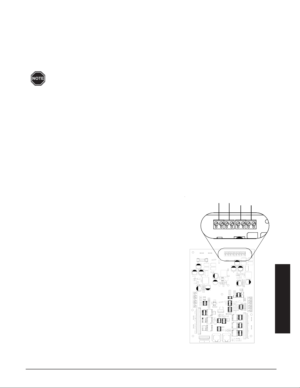
The building’s load management system is connected to the
ThermElect system with low voltage wire. The wires are routed into
the electrical panel and connected to the terminals for 4-20ma on the
relay driver board (Figure 21).
Other external loads are generally controlled through the building’s
load management control system.
4-20 MILLI-AMP OR PULSE
MONITORING CONNECTIONS
FIGURE 21
Not
Used
Aux
Aux
Status
Duct
Duct
Sensor
Duct
Made In USA
Relay Driver
Core C D E
20V
S
E
D
C
R
E
Y
R
D
Y
R
C
Y
20V
Right Limit
24VAC
24VAC
Warning For Continued Protection
Against Fire, Replace With
Same Type And Rating Fuse
R
Core F G H
H
Y
R
G
Y
R
F
Y
20V
20V
S
H
Left Limit
G
F
Relay Driver Control Board
AUX L AUX R
Pulse
-
-
Corporation
+
+
Steffes
Download
Connector
4-20ma
+
-
-
+
+
-
-
+
-
-
Pulse
4-20ma
Pulse
+5V
A/D Status
DownLoad
+
+
Load Management
THERMELECT LOAD MANAGEMENT 4.02
Page 26
PULSE MONITORING
The ThermElect system monitors pulse outputs from the power company's electric
meter. Program parameters such as desired maximum building kW and pulse ratios
for the metering system being used are entered into the ThermElect system. The
system then changes proportionally when demand free power is available. This
keeps the total building kW usage at or below the desired level.
To enable pulse monitoring, the 2 bit must be set in Location 53 (L053). Location 54
(L054) needs to be configured for the maximum load (load that can not be exceeded). This value is input as kW/10; therefore, if the maximum load is 1500 kW,
the value in L054 would be set to 150. Location 56 (L056) needs to be configured
for the input of a single heating element. For example, if the system is using 4,400
watt heating elements a value of 44 would be set in L056 (kW x 10).
To set the number of pulses per kWh, access the ELOC locations and set “E000”
to the correct value. Input is registered as (# of pulses/kWh) X 10.
The pulse monitoring device is connected to the ThermElect system with low voltage wire. The wires are routed
into the electrical panel and connected to the “pulse” terminals on the relay driver board (Figure 21).
With pulse monitoring, there are many options available for load control. The ThermElect system may be the only
load being controlled with the pulse monitoring or other loads can be controlled by the relay driver board or up to
two (2) external load management control modules (Order Item #1908410) can be added. Each module has eight
(8) zones which can be controlled, for a total of sixteen (16). Configuration of the locations values and the ELOC
locations will vary depending on the application and controls utilized. For more information on the proper settings,
reference the Supplemental Installer’s Guide or contact Steffes Technical Support at 1-888-783-3337.
Load Management
LOAD MANAGEMENT 4.03 THERMELECT
Page 27

A
Appendix
SPECIFICATIONS
MODEL 8150
Input Voltage 240 120/208 120/240 277/480 347/600
Phase 1 3 3 3 3
Number of Wires 2 3 3 4 4
Charging Input (kW) 53.3 48.0 53.3 50.4 53.3
Elements - Quantity
Elements - Watts Each
Amps – Core Charging 222.20 133.39 128.44 60.65 51.23
Max. Core & Blower Load (AMPS) 3.0 7.4 7.4 2.3 3.0
Minimum Circuit Ampacity 281.50 175.99 169.80 78.69 67.78
Blowers/System Control Voltage 240V/208V 240V/208V 240V/208V 240V/208V 240V/208V
Storage Capacity - kWh
Storage Capacity - BTU
Approximate Storage Module Weight (lbs) 770
Approximate Insulation Block, Air Handler,
Elements & Other Weight (lbs)
Approximate Brick Weight (lbs) 3,440
Approximate Installed Weight (lbs) 4,540 (add approx. 500 lbs to arrive at shipping weight)
Number of Brick 192
12
4,444
12
4,000
330 (utilizing 2000 CFM Air Handler)*
12
4,444
320
1,091,840
12
4,200
12
4,444
MODEL 8155
Input Voltage 240 120/208 120/240 277/480 347/600
Phase 1 3 3 3 3
Number of Wires 2 3 3 4 4
Charging Input (kW) 106.6 96.0 106.6 100.8 106.6
Elements - Quantity
Elements - Watts Each
Amps – Core Charging 444.40 266.79 256.88 121.30 102.46
Max. Core & Blower Load (AMPS) 3.0 7.4 7.4 2.3 3.0
Minimum Circuit Ampacity 559.25 342.73 330.35 154.50 131.82
Blowers/System Control Voltage 240V/208V 240V/208V 240V/208V 240V/208V 240V/208V
Storage Capacity - kWh
Storage Capacity - BTU
Approximate Storage Module Weight (lbs) 770 per module = 1,540 Total
Approximate Insulation Block, Air Handler,
Elements & Other Weight (lbs)
Approximate Brick Weight (lbs) 3,440 per module = 6,880 Total
Approximate Installed Weight (lbs) 9,030 (add approx. 600 lbs to arrive at shipping weight)
Number of Brick 192 per module = 384 Total
* Optional 3000 CFM Air Handler increases approximate installed weight by 40 pounds.
24
4,444
24
4,000
610 (utilizing 2000 CFM Air Handler)*
24
4,444
640
2,183,680
24
4,200
24
4,444
Appendix
APPENDIX A.01 THERMELECT
Page 28
MODEL 8180
Input Voltage 240 120/208 120/240 277/480 347/600
Phase 1 3 3 3 3
Number of Wires 2 3 3 4 4
Charging Input (kW) 80.0 72.0 80.0 75.6 80.0
Elements - Quantity
Elements - Watts Each
Amps – Core Charging 333.30 200.09 192.66 90.97 76.84
Max. Core & Blower Load (AMPS) 3.0 7.4 7.4 2.3 3.0
Minimum Circuit Ampacity 420.38 259.36 250.07 116.59 99.80
Blowers/System Control Voltage 240V/208V 240V/208V 240V/208V 240V/208V 240V/208V
Storage Capacity - kWh
Storage Capacity - BTU
Approximate Storage Module Weight (lbs) 840
Approximate Insulation Block, Air Handler,
Elements & Other Weight (lbs)
Approximate Brick Weight (lbs) 5,160
Approximate Installed Weight (lbs) 6,400 (add approx. 600 lbs to arrive at shipping weight)
Number of Brick 288
18
4,444
18
4,000
400 (utilizing 2000 CFM Air Handler)*
18
4,444
480
1,637,760
18
4,200
18
4,444
MODEL 8185
Voltage 120/208 120/240 277/480 347/600
Phase 3 3 3 3
Number of Wires 3 3 4 4
Charging Input (kW) 120.0 133.3 126.0 133.3
Elements - Quantity
Elements - Watts Each
Amps – Core Charging 333.48 321.10 151.62 128.07
Max. Core & Blower Load (AMPS) 7.4 7.4 2.3 3.0
Minimum Circuit Ampacity 426.10 410.62 192.41 163.84
Blowers/System Control Voltage 240V/208V 240V/208V 240V/208V 240V/208V
Storage Capacity - kWh
Storage Capacity - BTU
Approximate Storage Module Weight (lbs) 770 (53kW) + 840 (80kW) = 1,610 Total
Approximate Insulation Block, Air Handler,
Elements & Other Weight (lbs)
Approximate Brick Weight (lbs) 8,600
Approximate Installed Weight (lbs) 10,940 (add approx. 650 lbs to arrive at shipping weight)
Number of Brick 192 (53kW) + 288 (80kW) = 480 Total
* Optional 3000 CFM Air Handler increases approximate installed weight by 40 pounds.
30
4,000
730 (utilizing 2000 CFM Air Handler)*
30
4,444
30
4,200
800
2,729,600
30
4,444
Appendix
APPENDIX A.02 THERMELECT
Page 29
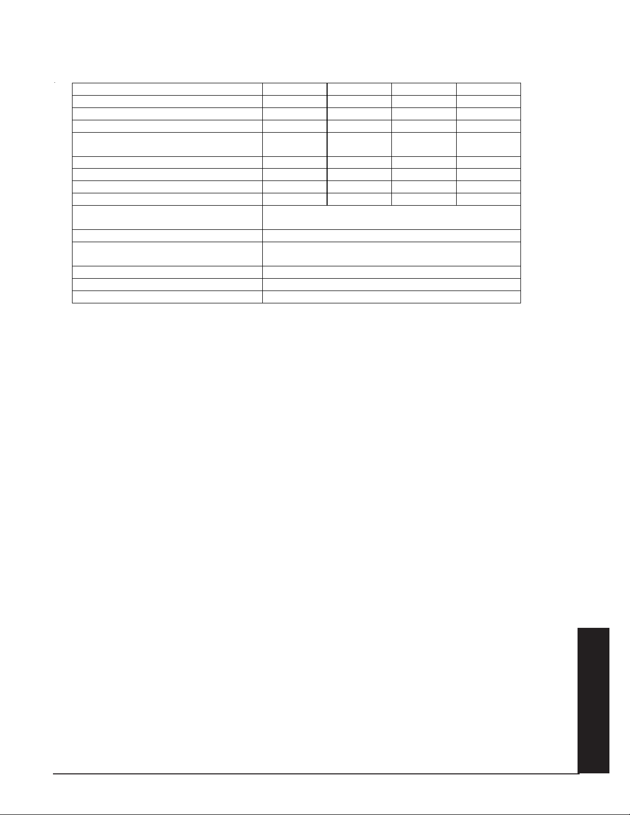
MODEL 8188
Input Voltage 120/208 120/240 277/480 347/600
Phase 3 3 3 3
Number of Wires 3 3 4 4
Charging Input (kW) 144.0 159.9 151.2 159.9
Elements - Quantity
Elements - Watts Each
Amps – Core Charging 400.18 385.32 181.95 153.68
Max. Core & Blower Load (AMPS) 7.4 7.4 2.3 3.0
Minimum Circuit Ampacity 509.47 490.90 230.31 195.85
Blowers/System Control Voltage 240V/208V 240V/208V 240V/208V 240V/208V
Storage Capacity - kWh
Storage Capacity - BTU
Approximate Storage Module Weight (lbs) 840 per module = 1,680 total
Approximate Insulation Block, Air Handler,
Elements & Other Weight (lbs)
Approximate Brick Weight (lbs) 10,320 Total
Approximate Installed Weight (lbs) 12,760 (add approx. 700 lbs to arrive at shipping weight)
Number of Brick 288 per module = 576 Total
* Optional 3000 CFM Air Handler increases approximate installed weight by 40 pounds.
36
4,000
760 (utilizing 2000 CFM Air Handler)*
36
4,444
4,200
960
3,275,520
36
36
4,444
THERMELECT APPENDIX A.03
Appendix
Page 30
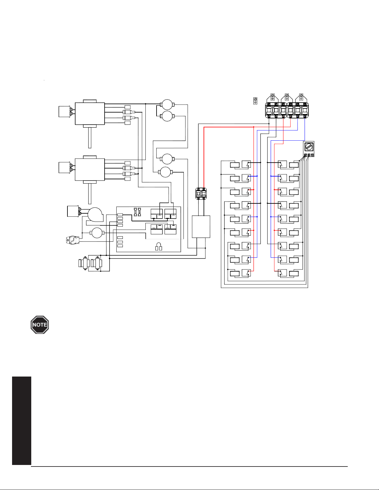
Typical System Line Voltage W iring Diagram
277/347 3 Phase 4 Wire - 3000 CFM
8180 APPLICATION
SUPPLY AIR BLOWER UPPER
10uf
Cap.
MED. HIGH
MED. LOW
SUPPLY AIR BLOWER LOWER
10uf
Cap.
Cap.
DAMPER
MOTOR
4uf
MED. HIGH
MED. LOW
CORE
BLOWER
WHITE
BLACK
TRANSFORMER
240v / 24v
160 °
N.C.
COM.
HIGH
LOW
COM.
HIGH
LOW
WHITE
BLACK
BLUE
YELLOW
RED
WHITE
BLACK
BLUE
YELLOW
RED
5 Amp
L1
L2 120
L2 240
BLOWER
RESISTOR
RESISTOR
DAMPER
BASE IO BOARD
BLACK/YELLOWBLACK/YELLOW
RED
BLUE/BLACK
BLUE/RED
1/4 Amp
MANUAL RESET
E
L
U
E
/
B
T
I
H
W
190 °
COM
NO
FAN ON
RELAY
N.C.
170 °
N.C.
ORANGE/BLACK
BLACK/YELLOW
MANUAL RESET
190 °
N.C.
170 °
N.C.
COM
NO
NO
COM
HEAT CALL
RELAY
BLUE/WHITE
BLUE
NO
COM
Transformer
240 VAC Secondary
Element
#18 Left
Element
#16 Left
Element
#14 Left
Element
#12 Left
Element
#10 Left
Element
#8 Left
Element
#6 Left
Element
#4 Left
Element
#2 Left
Element Relay
#18 Left
Element Relay
#16 Left
Element Relay
#14 Left
Element Relay
#12 Left
Element Relay
#10 Left
Element Relay
#8 Left
Element Relay
#6 Left
Element Relay
#4 Left
Element Relay
#2 Left
Ground
Lug
Element Relay
#17 Right
Element Relay
#15 Right
Element Relay
#13 Right
Element Relay
#11 Right
Element Relay
#9 Right
Element Relay
#7 Right
Element Relay
#5 Right
Element Relay
#3 Right
Element Relay
#1 Right
Element
#17 Right
Element
#15 Right
Element
#13 Right
Element
#11 Right
Element
#9 Right
Element
#7 Right
Element
#5 Right
Element
#3 Right
Element
#1 Right
Neutral
Use copper or aluminum conductors rated for 75oC or higher for field connection of this device.
Appendix
APPENDIX A.04 THERMELECT
Page 31
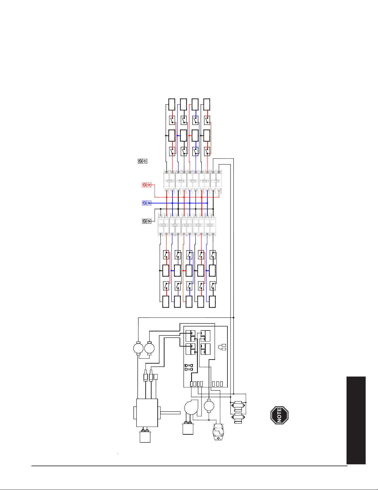
Typical System Line Voltage Wiring Diagram
208/240 3 Phase 3 Wire - 2000 CFM
8180 APPLICATION
#15
Lug
Ground
#17#18
Element
Element
#18 Relay #17 Relay
#13
#11
Element
Element
#15 Relay
#16
Element
#16 Relay
Element
#13 Relay
#11 Relay
#12
#14
Element
Element
#12 Relay
#14 Relay
C or higher for field connection of this device.
#6 Relay
#4 Relay
#6
#5
L1
Cap.
COM COM
CORE
#3 Relay
NO
NO
L2 240
L2 120
BLOWER
#2 Relay
#4
Element
#1 Relay
Element#3Element
COM
RELAY
NO
HEAT CALL
COM
RELAY
FAN ON
NO
BLOWER
160 °
WHITE
BLACK
DAMPER
#2
Element
#1
BLUE/WHITE
BASE IO BOARD
RED
BLACK/YELLOWBLACK/YELLOW
RESISTOR
RESISTER
DAMPER
N.C.
240v / 24v
TRANSFORMERS
MOTOR
#8 Relay
#10 Relay
#8
#10
Element
#9 Relay
#9
Element
BLUE
BLUE/WHITE
N.C.
N.C.
170 °
190 °
MANUAL RESET
WHITE
COM.
BLUE/BLACK
BLUE/RED
BLUE
RED
BLACK
LOW
HIGH
Element
Element
#5 Relay
#7 Relay
#7
Element
Element
1/4 Amp
5 Amp
MEDIUM
SUPPLY AIR BLOWER
Cap.
10uf
4uf
o
Use copper or aluminum conductors rated for 75
Appendix
THERMELECT APPENDIX A.05
Page 32
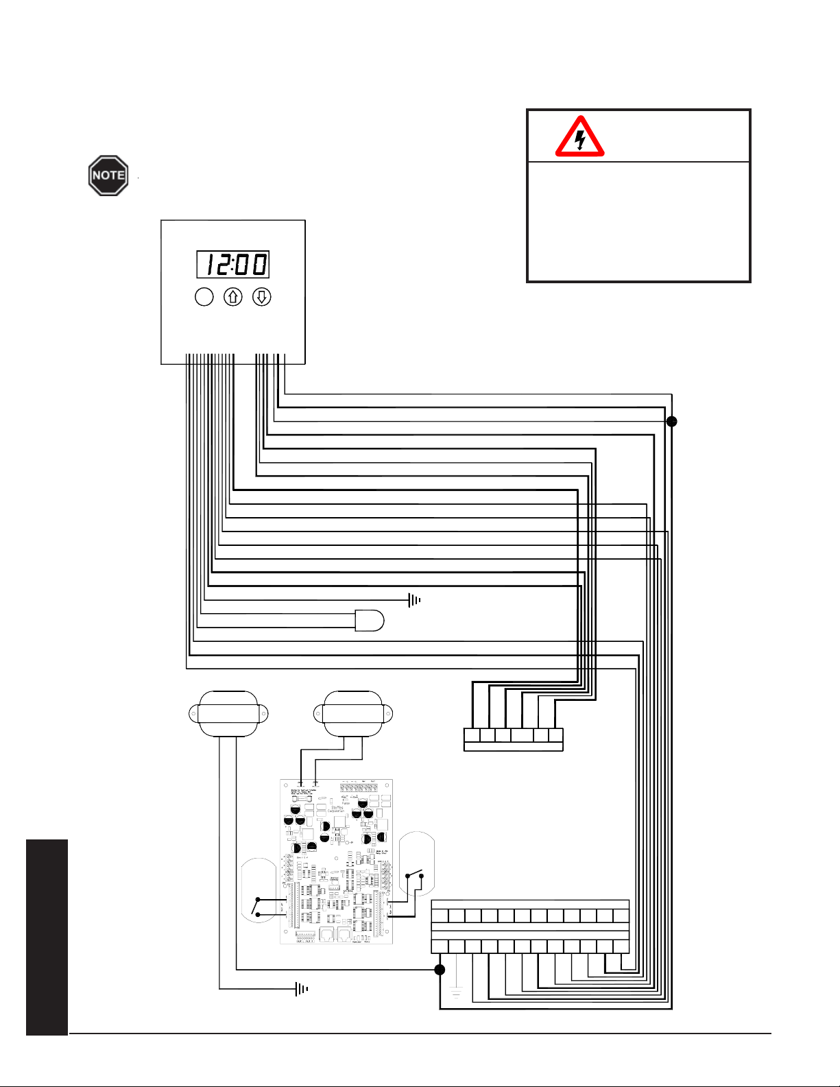
INTERNAL SYSTEM WIRING DIAGRAM - LOW VOLTAGE
The outdoor temperature sensor, room thermostat, and peak control device are connected via low voltage wiring.
System Low Voltage Wiring Diagram
W ARNING
The "R" and "C" positions in the low voltage terminal
strip may be used as a source of 24 VAC for powering
external low voltage devices (30 VA maximum).
A
M
P
M
M
YELLOW
YELLOW/BLUE
ORANGE
ORANGE/BLUE
BLUE/WHITE
BLUE
BLUE/RED
BLUE/RED
RED
WHITE
YELLOW
ORANGE
GREEN
BLUE/YELLOW
BLUE/WHITE
BLACK
BROWN
BROWN
GRAY
GRAY/WHITE
PURPLE
TX1 TX2
75 VA
TRANSFORMER
75 VA
TRANSFORMER
C
R
DISCHARGE AIR SENSOR
RP P
Peak Control Connections
HAZARDOUS VOLTAGE: Risk
of electric shock, injury, or
death. All low voltage wiring
must be segregated from line
voltage circuits in the system.
COM
NO
NC
AP
CORE
LIMITS
MODULE
ONE
Terminals for Connection as a Stand Alone Furnace
RC
Terminals for Connection with Heat Pump
RC
YWG
Y2
Y
G
O
O2Y2E SCSCRS
W2
W
OS
OS
RS
Appendix
CORE
LIMITS
MODULE
TWO
BLUE
YELLOW
APPENDIX A.06 THERMELECT
Page 33
HELP MENU
The system contains a Help Menu which may be accessed through the control panel. To access the Help Menu,
press and release the M button until the faceplate displays “HELP”. Scroll through the menu by pressing either
the up or the down arrow button.
Display
Reading Description
Fxxx Firmware Version Number - Indicates the version of software installed.
O xx Outdoor Temperature - Indicates current outdoor temperature as recognized by the system.
tL:xx Target Level - Indicates the percentage of brick core charge level the system is targeting. During
peak periods the value displays as "tL_".
CL:xx Charge Level - Indicates the percentage of heat storage currently in the brick core.
HE x Heating Elements Active - Indicates the total number of heating elements currently energized.
PC x Power Line Carrier Channel - Indicates the channel on which the system is set to receive PLC
communication signal.
P x Power Line Carrier Net Hit Rate Percentage - Indicates the percentage of "GOOD" communication
packets received by the system from the PLC transmitter system.
PS x Indicates which Specialty Timer the system is currently using. The value displayed will be zero if
the Specialty Timer is not being utilized.
CC_x Charge Mode Operation - Indicates the charge control method being utilized during off-peak periods.
CA_x A-Peak Mode Operation - Indicates the charge control method being utilized during anticipated peak
periods.
C1_x Specialty Timer #1 Charge Mode - Specialty Applications Only.
C2_x Specialty Timer #2 Charge Mode - Specialty Applications Only.
W ARNING
ERROR CODES
The system has an on-board diagnostic system to monitor various operating
conditions. If operating conditions move outside the normal operating range, an
error code is displayed on the faceplate. If there are multiple errors simultaneously, only the highest priority error code appears. Once corrected, the next
highest priority code will be displayed on the faceplate as “Er—” (i.e., Er05).
Error Code # Description
0 1 Currently not utilized.
0 2 Currently not utilized.
0 3 Currently not utilized.
04 Discharge air sensor temperature is out of normal operating range. This can indicate an open sensor, a
short in the wiring, or a circuit board which is out of calibration. Take an ohm reading across the
sensor to ensure proper operation, check the wiring, and verify the value in L035. Verify that the
supply air blower is connected to the supply blower wiring harness located in the base of the system.
Compare the sensor reading to the value in L112 to verify proper calibration of the circuit board.
Approximate ohm readings are 70° F = 1,199 ohms; 80° F = 941 ohms; 95° F = 646 ohms.
05 Outdoor sensor (direct wired) temperature reading is out of normal operating range. The sensor circuit
may be open or shorted, the processor control board may be out of calibration, or there may be an
incorrect value in L035. If using power line carrier control, make sure the values in L020 and L035 have
been set appropriately. Otherwise, verify that the outdoor sensor is connected to OS and SC on the
12-position terminal block. Compare the sensor reading to the value in L113 to verify proper calibration
of the circuit board. Approximate ohm readings are 5° F = 7,646 ohms; 50° F = 2,024 ohms; 95° F =
646 ohms.
HAZARDOUS VOLTAGE:
Risk of electric shock,
injury, or death. System
may be connected to more
than one branch circuit.
Disconnect power to all
circuits before servicing.
Equipment must be
serviced by a qualified
technician.
Appendix
THERMELECT APPENDIX A.07
Page 34

Error Code # Description
0 6 Outdoor temperature reading from the transmitting device (PLC system) is out of normal operating
range. Check the outdoor sensor attached to the transmitting device and the transmitter for proper
operation.
07 Main processor control board temperature sensor is out of normal operating range. Verify that none
of the clearances have been violated and inspect the condition of the processor control board.
08 External duct sensor temperature is out of normal operating range. This can indicate an open sensor,
a short in the wiring, or the relay driver board is out of calibration. Take an ohm reading across the
sensor to ensure proper operation, check the wiring, and verify the value in L053. Compare the sensor
reading to the value in L144 to verify proper calibration of the circuit board. Approximate ohm
readings are 60° F = 1552 ohms; 70° F = 1199 ohms; 80° F = 941 ohms. Max 190°F, Min 0°
09 Aux. Analog input is out of normal operating range. Currently not used.
1 0 Discharge air temperature has exceeded maximum standard operating temperatures.
11 Core C thermocouple temperature is out of normal operating range. An open, shorted, or otherwise
defective thermocouple or a circuit board which is out of calibration can cause this. Check the
thermocouple by taking a millivolt reading of the thermocouple. Compare the thermocouple reading to
the value in L136 to verify proper calibration of the circuit board. Approximate DC mV readings are
200° F = 3.8 mV; 700° F = 15.2 mV; 1200° F = 27.0 mV. Max. 1700°F, min 0°F
12 Core D thermocouple temperature is out of normal operating range. An open, shorted, or otherwise
defective thermocouple or a circuit board which is out of calibration can cause this. Check the
thermocouple by taking a millivolt reading of the thermocouple. Compare the thermocouple reading to
the value in L137 to verify proper calibration of the circuit board. Approximate DC mV readings are
200° F = 3.8 mV; 700° F = 15.2 mV; 1200° F = 27.0 mV. . Max. 1700°F, min 0°F
13 Core E thermocouple temperature is out of normal operating range. An open, shorted, or otherwise
defective thermocouple or a circuit board which is out of calibration can cause this. Check the
thermocouple by taking a millivolt reading of the thermocouple. Compare the thermocouple reading to
the value in L138 to verify proper calibration of the circuit board. Approximate DC mV readings are
200° F = 3.8 mV; 700° F = 15.2 mV; 1200° F = 27.0 mV. . Max. 1700°F, min 0°F
14 Core F thermocouple temperature is out of normal operating range. An open, shorted, or otherwise
defective thermocouple or a circuit board which is out of calibration can cause this. Check the
thermocouple by taking a millivolt reading of the thermocouple. Compare the thermocouple reading to
the value in L139 to verify proper calibration of the circuit board. Approximate DC mV readings are
200° F = 3.8 mV; 700° F = 15.2 mV; 1200° F = 27.0 mV. . Max. 1700°F, min 0°F
15 Core G thermocouple temperature is out of normal operating range. An open, shorted, or otherwise
defective thermocouple or a circuit board which is out of calibration can cause this. Check the
thermocouple by taking a millivolt reading of the thermocouple. Compare the thermocouple reading to
the value in L140 to verify proper calibration of the circuit board. Approximate DC mV readings are
200° F = 3.8 mV; 700° F = 15.2 mV; 1200° F = 27.0 mV. . Max. 1700°F, min 0°F
16 Core H thermocouple temperature is out of normal operating range. An open, shorted, or otherwise
defective thermocouple or a circuit board which is out of calibration can cause this. Check the
thermocouple by taking a millivolt reading of the thermocouple. Compare the thermocouple reading to
the value in L141 to verify proper calibration of the circuit board. Approximate DC mV readings are
200° F = 3.8 mV; 700° F = 15.2 mV; 1200° F = 27.0 mV. . Max. 1700°F, min 0°F
17 Load Control Device (4-20mA) is out of normal range. This can indicate an open sensor, a short in the
wiring, or a relay driver board is out of calibration. Take a mA reading across the input to ensure
proper operation, check the wiring, and verify the value in L053. Compare the sensor reading to the
value in L142 to verify proper calibration of the circuit board. All heating elements should be turned
off. Max. 25mA, min 2mA
18 Pulse reading is not functional. The pulse input is reading is indicating 0 load even though there are
elements, 2 minimum, turned on. All loads should be turned off.
Appendix
1 9 There is no communication occurring with the relay driver board. The interface cable may be defec-
tive or the relay driver board may be unresponsive. Verify that the values in L090, L091, and L092 are
correct for the application.
APPENDIX A.08 THERMELECT
Page 35

Error Code # Description
20 There is no communication occurring between the Base I/O board and the processor control board. A
defective board interface cable or an unresponsive Base I/O board can cause this.
2 1 There is no communication occurring with the first relay expansion board. The interface cable may be
defective or the first expansion board may be unresponsive. Check the jumper configuration on the
relay expansion board to ensure that J1 and J2 are both in the “OFF” position. Verify that the values
in L090, L091, and L092 are correct for the application.
22 There is no communication occurring with the second relay expansion board. The interface cable may
be defective or the second expansion board may be unresponsive. Check the jumper configuration on
the expansion board and make sure J1 is “ON” and J2 is “OFF”. Verify that the values in L090, L091,
and L092 are correct for the application.
2 3 There is no communication occurring with the Steffes Time Clock Module. If this module is installed,
verify the value in L035. If correct, the interface cable or the time clock module may be defective.
24 Temperature sensor offset/reference is out of range and indicates that one of the sensors or the core
thermocouple may be shorted to ground or the processor control board may be out of calibration.
25 Power line carrier system is active; however, no good data has been received.
2 6 Insufficient main control board memory. Contact a qualified service technician.
2 7 Insufficient permanent memory. Contact a qualified service technician.
28 Permanent memory change has been made. Press the M button to accept. This error message
indicates a change has been made to the software program; therefore, it is important to verify that all
location settings are correct for the application.
2 9 On-board communication system is not fully operable. Contact a qualified service technician.
30 Base control board is in test mode. Check the jumper configuration on the circuit board.
3 1 Relay expansion board(s) are in test mode. Check the jumper configuration.
39 Indicates the value in Location 13 (L013) has been set to a value greater than the value in Location 12
(L012). The system will not charge until the value in L013 is set lower than L012.
4 0 Location Values are lost. The EPROM will be updated to the values saved in the main program. Clear
error by touching the M button on the heater. If this will not clear the error, replace the processor
board.
41 This error may appear when configuring the heater. Clear error by touching the M button on the
heater. If this will not clear the error, replace the processor board.
4 2 Internal communication error. Reprogram or replace processor circuit board.
4 3 An attempt to load configuration using LO 98 set to 20, 30, 40, or 50 has failed. Each location values
will need to be manually set.
Cold Core Temperature of the brick core is below 40 degrees or the core sensing thermocouple may be open.
Verify that the core thermocouple wiring is connected properly and that the values in L090, L091 and
L092 are correct for the application. If the value in L110 is reading 30, then the thermocouple is open.
Core Fail Core high limit switch may be open.
PLC Fail The system is configured for power line carrier control; however, is not receiving a valid power line
carrier communication signal.
LoAd CAP All controllable loads have been shed and Maximum Load Capacity is still exceeded.
THERMELECT APPENDIX A.09
Appendix
Page 36

W
Registering your purchase is an essential step to ensure warranty coverage. A Warranty Registration card
is included with the Owner's Manual. Simply complete, detach the bottom portion, and return the card
today. Retain the top portion of the card for your files.
WARRANTY STATEMENT
Steffes Corporation (“Steffes”) warrants that the Steffes Electric Thermal Storage Heating Appliance is
free from defects in materials and workmanship under normal use and service. Steffes’ obligation under
this Warranty is limited to the repair or replacement of the appliance or parts only, which prove to be
defective under normal use within two (2) years of the date of installation and which Steffes’ examination of the
returned appliance or part(s) shall verify to Steffes’ satisfaction that it is defective. The user shall be responsible
for any labor costs associated with the repair or replacement of the appliance or part(s), including the cost of
returning the defective appliance or part(s) to Steffes Corporation.
This Warranty is void if the heating appliance is moved from the premises in which it was originally
installed. This Warranty shall not apply to an appliance or part which has been altered in any respect, or
improperly installed, serviced or used, or has been subject to accident, negligence, abuse or misuse.
Warranty
THE ABOVE WARRANTY BY STEFFES IS EXCLUSIVE AND IN LIEU OF ALL OTHER
WARRANTIES, WHETHER WRITTEN OR ORAL, EXPRESSED OR IMPLIED, INCLUDING
ANY IMPLIED WARRANTY OF MERCHANTABILITY OR OF FITNESS FOR A PARTICULAR PURPOSE.
The user assumes all risk and liability whatsoever resulting from the use of this heating appliance. In no
event shall Steffes be liable for any indirect, special or consequential damages or lost profits.
This Limited Warranty contains the complete and exclusive statement of Steffes’ obligations with respect
to the heating appliance and any parts thereof. The provisions hereof may not be modified in any respect
except in writing and signed by a duly authorized officer of Steffes.
Thank you for purchasing Steffes ETS heating equipment. We welcome your comments
relating to this manual. Enjoy your new purchase!
3050 Hwy 22 North • Dickinson, ND 58601-9413 • 701-483-5400
 Loading...