

Page 1
V2
"Manufactured in North America"
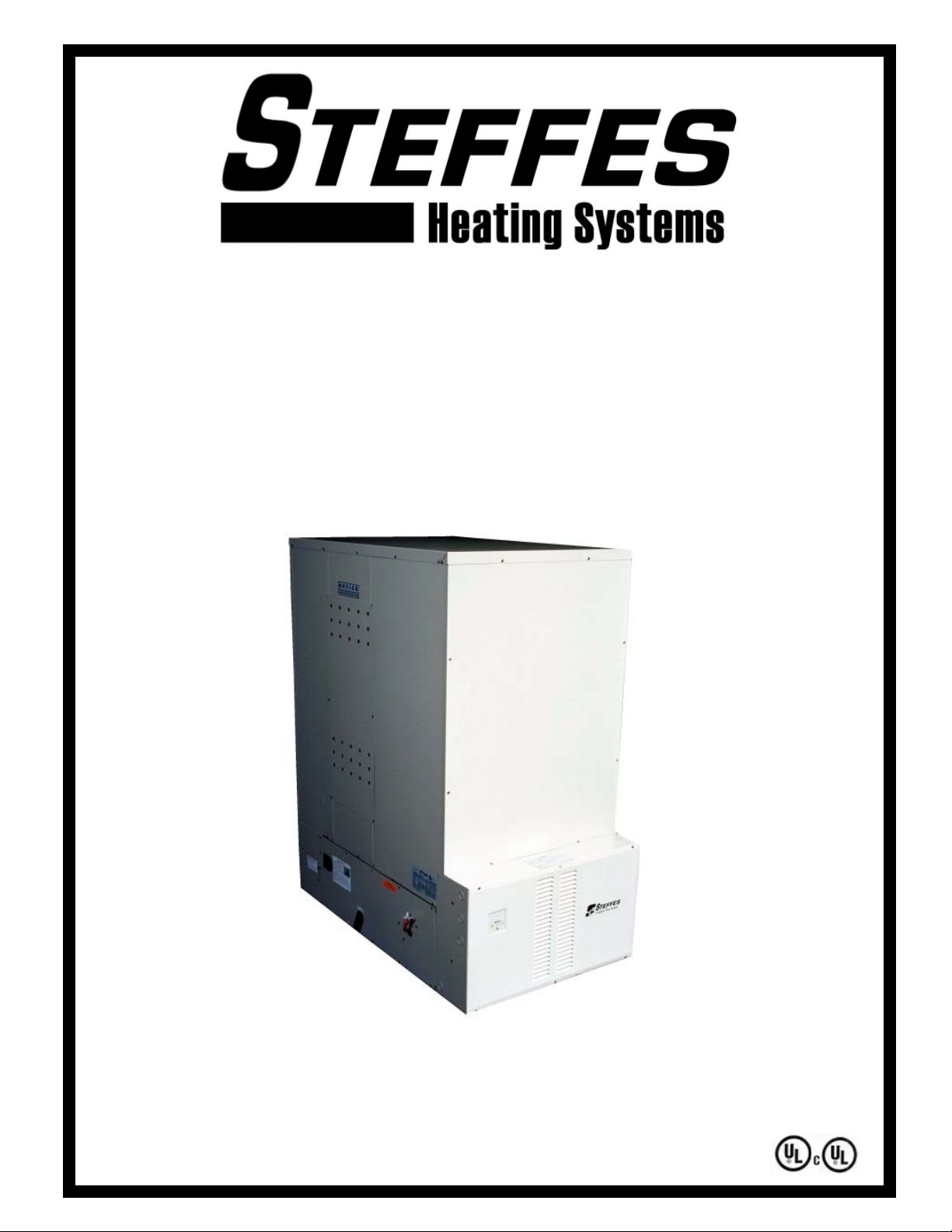
COMFORT PLUS COMMERCIAL
HYDRONIC HEATING SYSTEM
Owners and Installers Manual
Models: 7120, 7130 & 7140
Applicable to Software Version 2.0X
Page 2
IMPORTANT
w The equipment described herein is intended for installation by a qualified
technician in compliance with applicable local, state, and national codes and
requirements.
w To insure proper installation and operation of this product, completely read all
instructions prior to attempting to assemble, install, operate, maintain or repair
this product. Upon unpacking of the system, inspect all parts for damage prior
to installation and start-up.
w This manual should be retained by the owner upon completion of the installa-
tion and made available to service personnel as required.
w Disclaimer: In compiling this manual, Steffes Corporation has used its best
judgement based upon information available, but disclaims any responsibility
or liability for any errors or miscalculations contained herein, or any revisions
hereof, or which result, in whole or in part, from the use of this manual or any
revisions hereof.
After the heating system is installed, Steffes disclaims any responsibility or
liability for mold/mildew growth and/or any damages caused by either. We
strongly recommend that the user follow the moisture, mold and mildew prevention guidelines of the Environmental Protection Agency (EPA), available at
http://www.epa.gov.
For Customer Use
Please record your model and serial number below. This number is found on the identification label
located on the lower left side of the Comfort Plus Commercial Hydronic heating system. Retain this
information for future reference.
Model No. ________________________________________________________________________
Serial No. ________________________________________________________________________
RECOGNIZE THESE SYMBOLS AS SAFETY PRECAUTIONS
It is important, both for your personal safety and to avoid possible damage
to the equipment and your property, that you observe the safety instructions given following these symbols.
Page 3
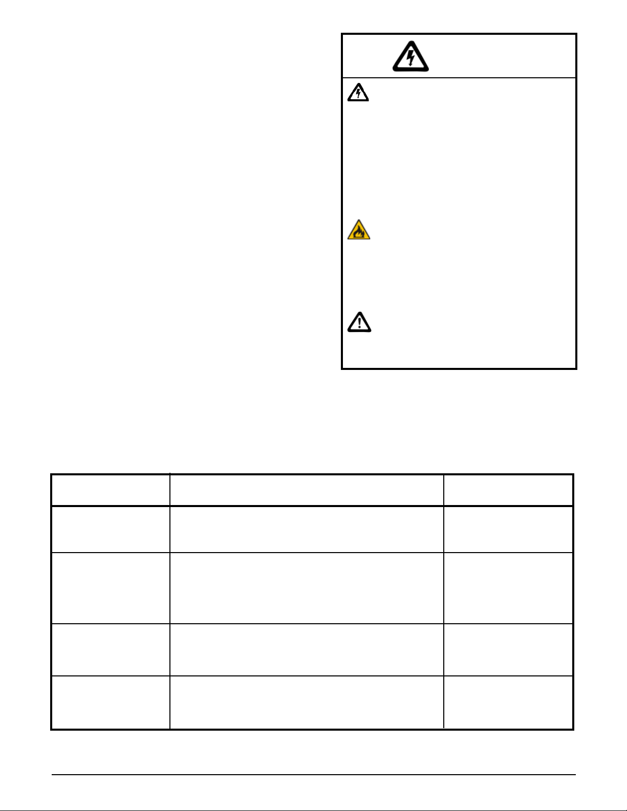
SAFETY PRECAUTIONS
1. DO NOT energize this heating system while disassembled or without the ceramic heat storage brick in
place.
2. DO NOT operate this heating system without the factory
provided pressure relief valve in place.
3. DO NOT use or store materials that may produce
explosive or flammable gases near the system.
4. DO NOT violate the placement and clearance requirements specified in this manual. (Page 3.02-3.03)
5. DO NOT place anything on top of the system.
6. Disconnect power to all circuits before servicing as this
heating system may be connected to more than one
branch circuit.
7. Use caution when working around the heating system as
inlet and outlet piping can be very hot.
8. Installation of and/or service to this system should be
performed by a qualified technician in compliance with
information contained herein and with national, state, and
local codes and requirements.
9. A repeated message display of CORE FAIL indicates
a need for service by a qualified technician.
WARNING
Risk of explosion. Can cause injury
or death. Operating the system
without the pressure relief valve
installed can cause an explosion.
Connect the pressure relief valve
in a vertical, upright position with
the supplied fittings. DO NOT
modify this assembly. DO NOT cap,
plug, or otherwise obstruct the
outlet of the pressure relief valve.
Risk of fire. Can cause injury or
death. Violation of the clearance
requirements can cause improper
operation of the equipment. Maintain the placement and clearance
requirements specified.
Risk of personal injury. Plumbing
and other surfaces can be hot. Use
caution when working near the
system.
SAFETY DEVICES
The Comfort Plus Commercial Hydronic incorporates safety devices to ensure normal operating temperatures are
maintained. The chart below describes these safety devices:
DEVICE NAME FUNCTION
Core Charging High
Limit Switches
(Auto Reset)
Heat Exchanger
Limit Switch
(Manual Reset)
These limit switches monitor brick core charging and
interrupt power to the heating elements if the normal
operating temperature is exceeded.
This linear limit switch monitors the temperature of the
water in the exchanger and interrupts power to the core
blower if a water temperature of 250
this limit switch opens, contact a qualified service technician.
Outlet Water
Temperature Limit
Switch (Auto Reset)
Pressure Relief Valve
This linear limit switch monitors the temperature of the
water in the exchanger and interrupts power to the core
blower if a water temperature of 225
If the water pressure exceeds 75 psig, the pressure relief
valve opens. Once water pressure of less than 75 psig is
achieved, the valve closes. (30 psig option available.)
o
F is exceeded. If
o
F is exceeded.
LOCATION
ON SYSTEM
In the limit bar panel
on the left side of the
brick storage cavity.
Inside base on left side.
Inside base on left side.
Factory provided,
field installed to outlet
port of furnace.
Comfort Plus Commercial Hydronic Safety Information
Page 4

Table of Contents
TC
Operation
General Operation .................................................................................................................................................................. 1.01
System Use During Construction Phase ................................................................................................................................ 1.01
System Start-up...................................................................................................................................................................... 1.01
Turning System "OFF" and "ON" ......................................................................................................................................... 1.01
Control Panel ......................................................................................................................................................................... 1.02
Operating Status .................................................................................................................................................................... 1.02
Temperature Control .............................................................................................................................................................. 1.03
Brick Core Charge Control ..................................................................................................................................................... 1.03
Charge Control Override ........................................................................................................................................................ 1.03
Maintenance and Cleaning .................................................................................................................................................... 1.03
Optional Accessories
Single Electrical Feed Kit ....................................................................................................................................................... 2.01
Primary Loop Kit .................................................................................................................................................................... 2.01
Static Heat Recovery Unit ...................................................................................................................................................... 2.01
18 "Stand ............................................................................................................................................................................... 2.02
Air Handler - Variable Speed .................................................................................................................................................. 2.02
Load Managment Control ...................................................................................................................................................... 2.03
SCR Controller ....................................................................................................................................................................... 2.04
External Duct Sensor .............................................................................................................................................................. 2.04
Control Circuit Step-Down Transformer ................................................................................................................................ 2.04
Installation
Shipping and Packaging ........................................................................................................................................................ 3.01
Placement and Clearance Requirements.......................................................................................................................... 3.02-3.03
Initial Set-up ........................................................................................................................................................................... 3.03
Brick Loading ......................................................................................................................................................................... 3.04
Heating Element and Air Channel Installation ................................................................................................................ 3.04-3.05
Brick Core Temperature Sensor Installation ........................................................................................................................... 3.05
Line Voltage Electrical Connections ............................................................................................................................... 3.06-3.07
Low Voltage Electrical Connections
Peak Control ............................................................................................................................................................ 3.07-3.08
Outdoor Temperature Sensor ......................................................................................................................................... 3.08
Room Thermostat .................................................................................................................................................... 3.09-3.10
Air Conditioner /Heat Pump Interface .................................................................................................................................... 3.10
Pressure Relief Valve Installation ........................................................................................................................................... 3.11
Plumbing ......................................................................................................................................................................... 3.11-3.13
Auxiliary Load Control ........................................................................................................................................................... 3.13
Configuration Menu ....................................................................................................................................................... 3.14-3.15
Installer's Final Check-out Procedure ..................................................................................................................................... 3.16
Appendix
Specifications ............................................................................................................................................................... A.01-A.02
Disassembling the Comfort Plus Commercial Hydronic System ........................................................................................... A.03
Internal System Wiring Diagrams - Line Voltage ......................................................................................................... A.04-A.09
Internal System Wiring Diagram - Low Voltage ........................................................................................................... A.10-A.15
Help Menu ............................................................................................................................................................................ A.16
Error Codes .................................................................................................................................................................. A.16-A.17
Glossary ................................................................................................................................................................................ A.18
Warranty
Table of Contents Comfort Plus Commercial Hydronic
Page 5

1
Operation
GENERAL OPERATION
The Comfort Plus Commercial Hydronic system stores demand free or off-peak electricity in the form of heat.
Operation of the heating system is automatic. During hours when energy costs are lower the system converts
electricity to heat which is then stored in its ceramic brick core. The amount of heat stored in the brick core of the
system varies in relation to outdoor temperature, current building load, utility peak conditions, and/or the heating
requirements.
A heat call from the thermostat or main system control energizes the primary water loop pump. The variable speed
core blower automatically adjusts its speed to achieve the desired outlet water temperature. The heated water is
then pumped to the area (zone) from which the heat call originated.
The versatility of this system allows it to fit many applications. The system is designed for use as either a sole
heating source (stand alone furnace) for make up air heating or as a supplement to another ducted heating
system such as a heat pump.
SYSTEM USE DURING CONSTRUCTION PHASE
Like most heating equipment manufacturers, Steffes strongly recommends that Construction Heating Units be
used instead of the permanent heating system during the construction phase of a new home. Use of the permanent heating system during the construction phase may contaminate the duct system and/or internal areas of the
heating system. This may cause poor indoor air quality issues and/or improper system operation once the home is
completed. A suitable alternative heating system must be used during the construction phase.
Operation
SYSTEM START-UP
On start-up of the Comfort Plus Commercial Hydronic, odors relating to first time operation of the heating components may be experienced. Allow the system to charge to its maximum brick core charge level, on start-up, to
expel these odors. If the system has not been used for an extended period of time, dust may accumulate in the
system. Upon restart, there may also be an odor as these dust particles are expelled.
During operation, the system may produce minor expansion noises. These noises are the result of the internal
components reacting to the temperature changes.
TURNING SYSTEM "OFF" AND "ON"
The system is fully automatic and does not need to be manually disabled. Talk to your installer or energy management person for additional information.
Comfort Plus Commercial Hydronic Operation n 1.01
Page 6
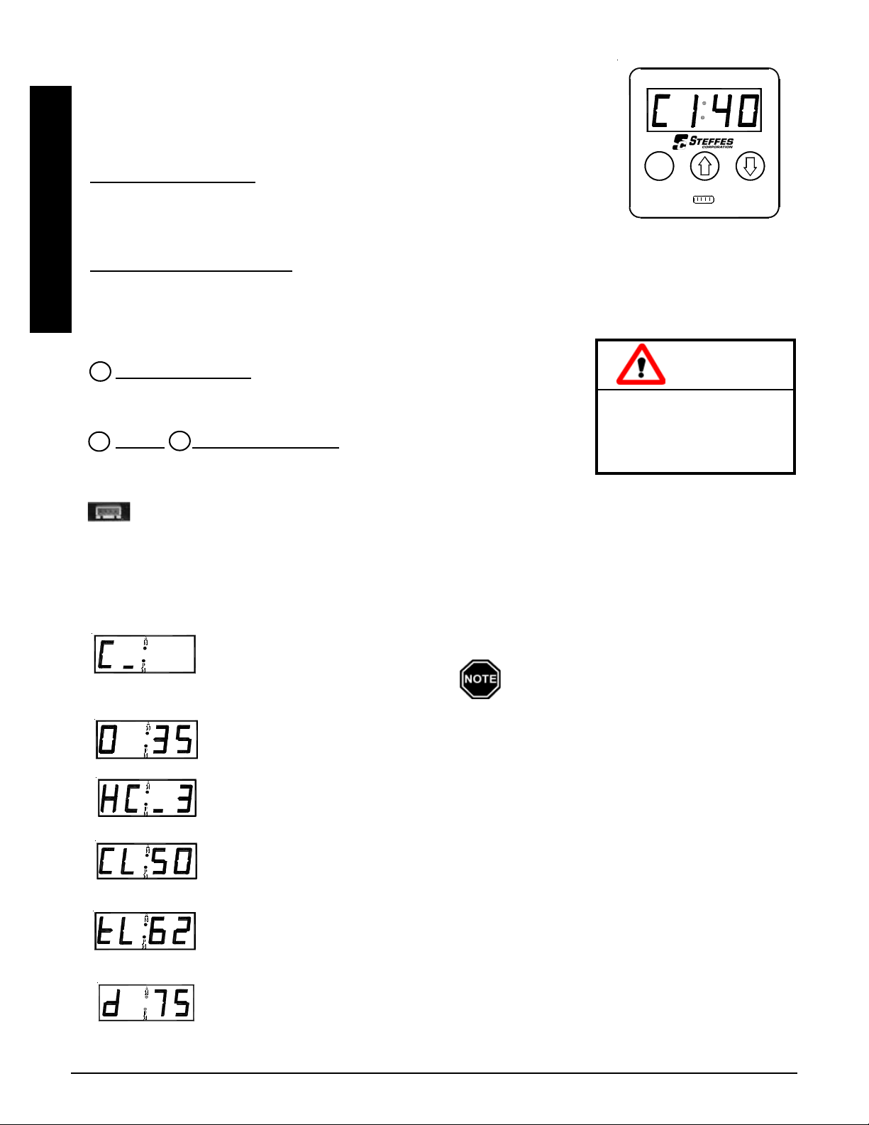
CONTROL PANEL
Operation of the Comfort Plus Commercial Hydronic system is automatic. All
operational functions are stored in its microprocessor in function locations and are
factory preset. If necessary, the installer can adjust them through the control panel.
(See Figure 1.)
AA
MM
PP
MM
Four-Digit LED Display
M
The four digit LED displays specific operating information. During an editing
process, the function locations and the values set in these locations are displayed for
viewing and adjusting purposes.
Operation
AM and PM Indicator Lights
CONTROL PANEL
FIGURE 1
The AM and PM indicator lights are only utilized if the Steffes Time Clock Module is being installed. With this
module installed, the system displays time on AM/PM intervals and the corresponding light flashes. The system
can be configured to display military time, in which case both the AM and PM
lights illuminate.
Mode (Edit) Button
M
Activates the editing menu for changing the operating information of the
system.
Up and Down Arrow Buttons
ñ
ò
Used to scroll up or down when viewing or changing
Editing operating
information may alter
the performance and
operation of the system.
CAUTION
operating functions.
Interface Port
FOR SERVICE USE ONLY! Allows technician external access for updating software and troubleshooting.
OPERATING STATUS
The Comfort Plus Commercial Hydronic system is set to display various operating information as described below.
Press and release the up arrow to view this data.
Operating Mode - Indicates the current operating mode of the system.
C = Off-Peak (Charge) Time
P = On-Peak (Control) Time
A = Anticipated Peak Time
A bar illuminates on the lower portion of
the display's second digit whenever one
or more heating elements are energized.
Outdoor Temperature -O followed by a number indicates current outdoor temperature.
Heat Call Status - Indicates the current heat call status being received from the room thermo-
stat. Refer to pages 3.11 and 3.12 for more information on heat call inputs.
Brick Core Charge Level - CL (charge level) followed by a number indicates the current
percentage of heat stored in the brick core. CL:_ represents zero percent and CL: F represents a full core charge level.
Targeted Brick Core Charge Level - tL (target level) followed by a number indicates the
current percentage of brick core charge being targeted by the system. A display of tL:_ indicates a target level of zero percent and tL: F indicates a full core charge target level.
Load Control - Current demand (kW) divided by 10. A value of d 75 is equal to a demand of
750kW.
Operation n 1.02 Comfort Plus Commercial Hydronic
Page 7

TEMPERATURE CONTROL
Temperature set point is adjusted at the wall thermostat(s) or the main system control. If temperature in the area
drops below the desired set point, a heat call is initiated and the primary loop pump is energized. The variable
speed core blower automatically adjusts speed in relation to brick core temperature to achieve the desired outlet
water temperatures. The heated water is then pumped to the area (zone) from which the call originated.
The versatility of this system allows it to fit many applications. The Comfort Plus Commercial Hydronic is designed for use as either the sole heating source (stand alone furnace) or as a supplement to ducted heating
systems such as heat pumps.
The Steffes Air Handler can be interfaced with a standard heat pump system and will provide comfort modulation. The system will monitor the outlet air temperature and modulate in heat from the Comfort Plus Commercial
Hydronic as needed to maintain the desired output air temperature. If one of the zones is a water coil used to
temper duct temperatures, an optional duct sensor (Order Item# 1041536) can be used.
BRICK CORE CHARGE CONTROL
The amount of heat stored in the brick core varies in relation to outdoor temperature, current building load, utility
peak conditions, and/or the heating requirements. The outdoor sensor, if installed, monitors outdoor temperature
and provides this information to the system. As the outdoor temperature decreases, heating requirements increase
and the system stores more heat accordingly.
The amount of heat stored in the system can also be regulated by a signal from a BACnet
control, energy management system, or serial communication input.
CHARGE CONTROL OVERRIDE
If desired, the Comfort Plus Commercial Hydronic system can be programmed to allow a charge control override.
This override allows the user to force the system to target a full core charge level and can be initiated or cancelled
at any time. If an override is initiated, the system targets a full core charge level during the next off-peak period. It
continues to charge during off-peak hours until it achieves full (maximum) core charge or until the override is
cancelled. Once full charge is achieved or the override is cancelled, the system charges according to the standard
configuration.
Operation
MAINTENANCE AND CLEANING
Any air filter(s) in the system should be replaced on a regular basis to ensure proper operation and to maintain
overall efficiencies. No additional routine maintenance is required.
If utilizing a heat pump or air conditioning system with the Comfort Plus Commercial Hydronic system, the indoor
coil should be cleaned periodically as dirt accumulation may reduce system efficiency. It is important to follow the
manufacturers maintenance and cleaning recommendations for these devices.
Comfort Plus Commercial Hydronic Operation n 1.03
Page 8
2
Optional Accessories
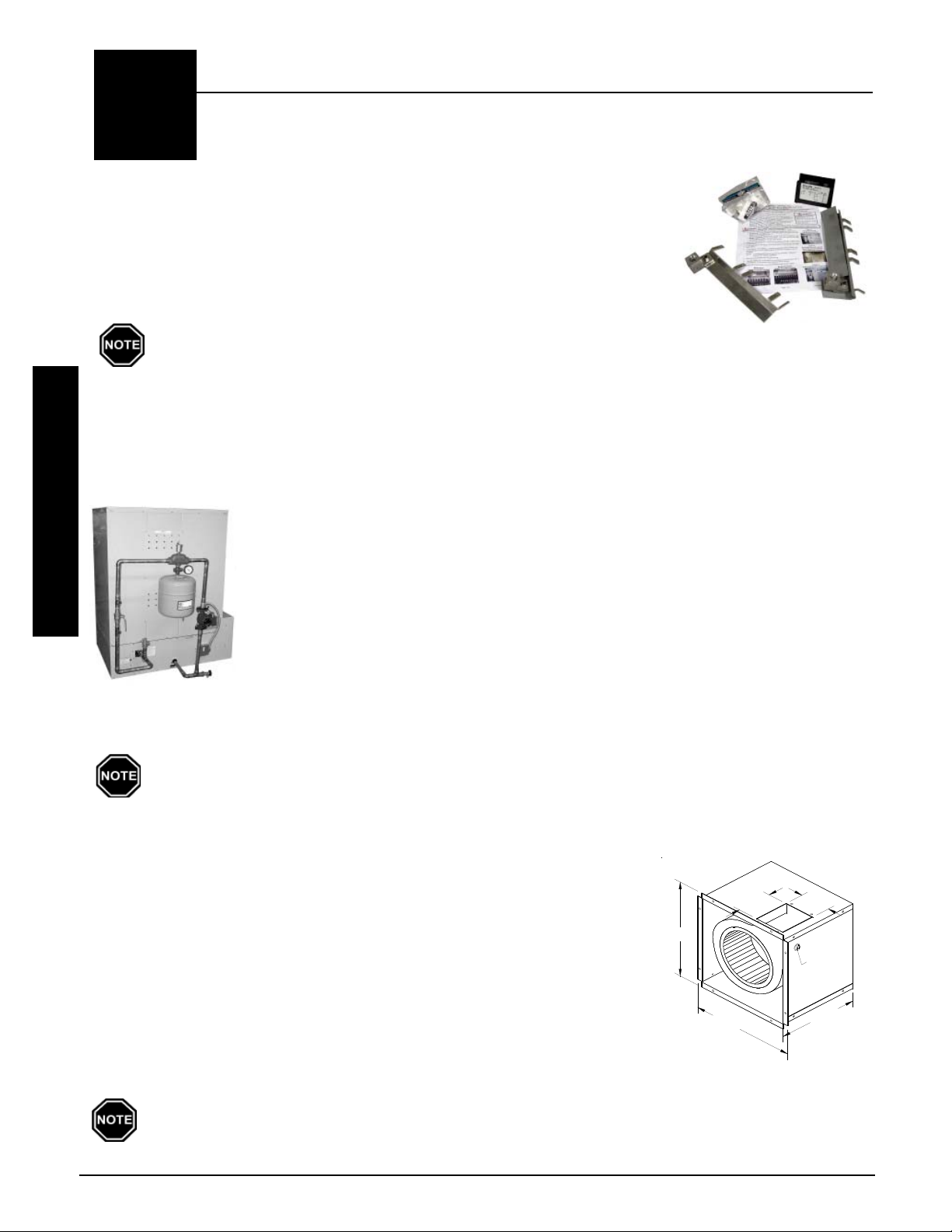
SINGLE ELECTRICAL FEED KIT
The Steffes Comfort Plus Commercial systems have built-in circuit breakers. They are
factory configured to be field connected to multiple line voltage circuits. If single feed
to the element and blowers/control circuits is desired, the single feed kit is available to
allow the system to be powered with a one, larger line voltage circuit. Contact the
factory for ordering details.
When using single feed, the neutral conductor MUST be sized in
208/240 Volt Only
accordance with all applicable local, state, and national codes and
regulations.
PRIMARY LOOP KIT
The Comfort Plus Commercial Hydronic system requires a primary water loop which serves to regulate heat transfer
from the units heat exchanger. To minimize installation time and costs for field design and engineering of this loop,
Steffes Corporation offers a primary loop kit. The kit contains the components generally installed with hydronic heat
systems.
Features:
Accessories
w Includes a 5-gallon diaphragm type expansion tank, Grundfos brand pump
(circulator), air separator, air vent, pressure gauge, and pump connection
conduit and fittings.
w Contains the appropriate valves to bleed air from the system during filling along
with automatic purge during system operation and draining.
w Incorporates isolation flanges for quick and easy servicing of the primary loop
pump (circulator).
Order Item #1302115
w Offers troubleshooting isolation between the heating system and secondary
zones.
STATIC HEAT RECOVERY UNIT
In applications using the Steffes Air Handler, the static heat recovery unit would not be used.
During operation of the Comfort Plus Commercial Hydronic system, some heat from the brick core storage will
radiate through its outer panels. If the system is located in an area with minimal heating requirements, such as a
utility room, the static heat recovery unit can maximize the systems efficiency
by transferring this static heat to a more desirable location.
Features:
w Connects directly to the Comfort Plus Commercial Hydronic system to
interface with the internal controls of the system for automatic operation.
w Specifications:
3.312
10.135
3.000
n
a
M
i
L
t
e
s
e
R
c
l
t
i
a
u
w
S
t
i
m
Wattage: 130 WATTS
Motor: .1 HP, 60 HZ
Voltage: 208/240 VAC
10.072
7.875
Maximum Static Pressure: .15 inches Water Column
CFM @.15 SP: 130 CFM
If the area available to install the Comfort Plus Commercial Hydronic system is less than 100
square feet, Steffes Corporation recommends installing a low voltage cooling thermostat,
connected between R and G on the 12-position terminal block, to maintain a temperature less
than 85 degrees Fahrenheit.
Optional Accessories n 2.01 Comfort Plus Commercial Hydronic
Order Item #1302110
h
Page 9
18" STAND
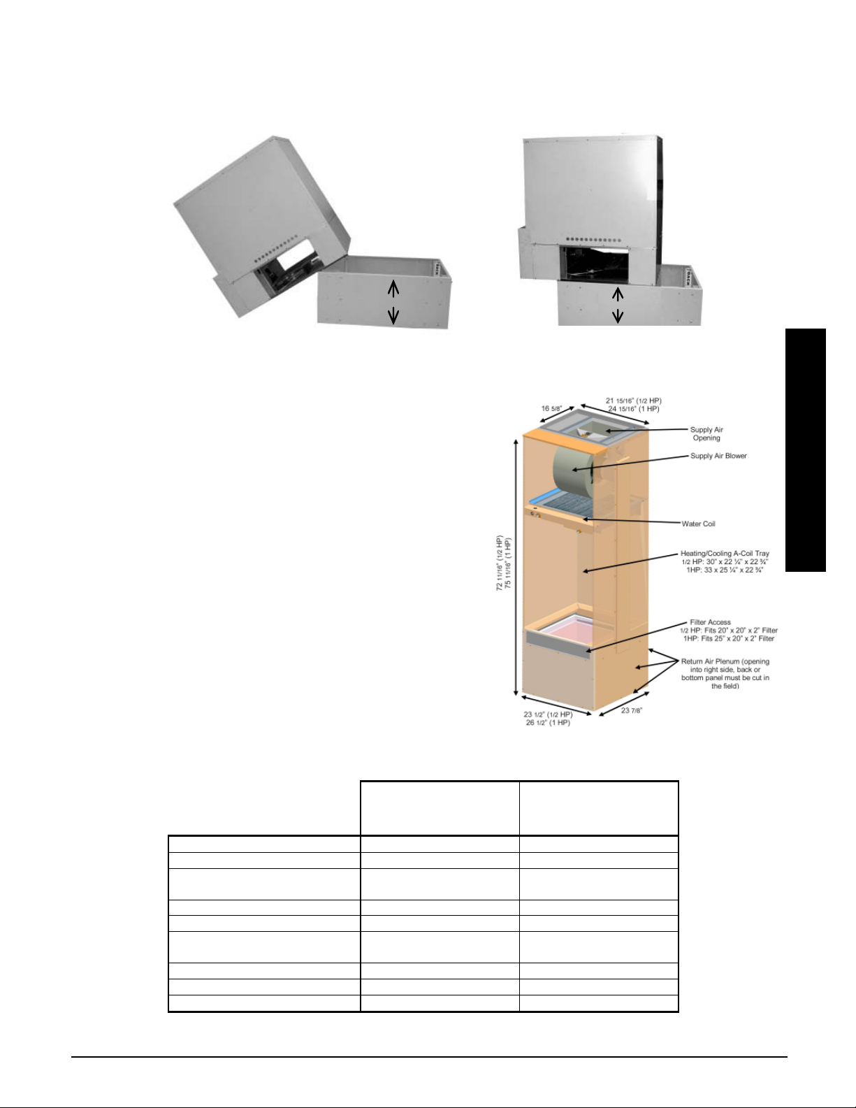
Some applications (such as garages) may require that the heating appliance be elevated in order to meet building codes.
The 18" stand can be used to elevate the 7140 series Comfort Plus Commercial Hydronic system. It is shipped as a
kit and requires field assembly. Support for the optional air handler is not provided.
Order Item #1301585
Stand
Stand
AIR HANDLER - VARIABLE SPEED
The Steffes Air Handler includes a return plenum, supply air
blower, water coil, and air filter.
The air handlers variable speed blower incorporates an ECM
motor that automatically adjusts its speed to achieve the appropriate CFM for the thermostat input received. Benefits include:
w Quieter operation
w Better dehumidification
w Offers greater operating efficiency by consuming 25% less
energy during normal operating mode which provides for
operating cost savings to the consumer. In continuous fan
mode, low speed energy savings can be greater than 70% in
comparison to a standard fixed motor speed.
w Interfaces with single or multi-speed air conditioner or heat
pumps. With multi-speed systems, it operates at the lower
speed most of the time. Only on extremely hot and cold
days does it operate at a higher speed. This staged heating
and cooling eliminates temperature swings, enhances
comfort and optimizes efficiency.
w Improved air filtration in continuous fan mode
w Constant air flow over a wide range of static conditions, even if filters are dirty or registers are closed.
Accessories
Order Item Number 1302132 1302134
Approximate Weight 200 lbs 228 lbs
Maximum Static Pressure
(inches water column)
Maximum Water Coil Output 60,000 BTU/hr 90,000 BTU/hr
Maximum Outlet Temperature 120oF 120oF
A-Coil Tray Dimensions
(HxWxD)
Voltage 240/208 VAC 240/208 VAC
Wattage 560W 1,050W
CFM ratings 1000, 1200, 1400, 1600 1200, 1400, 1600, 2000
w ½ HP variable speed accommodates most 1.5 to 4 ton heating/cooling systems
½ HP, 60 HZ
Variable Speed ECM
Air Handler
.75 inches H
30” x 22 5/16” x 22 3/4” 33” x 25 5/16”x 22 3/4”
0 .75 inches H20
2
1 HP, 60 HZ
Variable Speed ECM
Air Handler
w 1 HP variable speed accommodates most 3 to 5 ton heating/cooling systems
Comfort Plus Commercial Hydronic Optional Accessories n 2.02
Page 10
LOAD MANAGEMENT CONTROL
The Comfort Plus Commercial Hydronic system is an Electric Thermal Storage (ETS) heating system using electricity
to provide a low cost heating solution for commercial, industrial, and large residential applications. ETS equipment
is designed to store electricity, as heat, during hours when energy costs are lower and kW demand charges are not
incurred. The Comfort Plus Commercial's thermal mass consists of a high-density ceramic brick capable of vast
heat storage.
The system is designed to operate under one of three different load management control strategies.
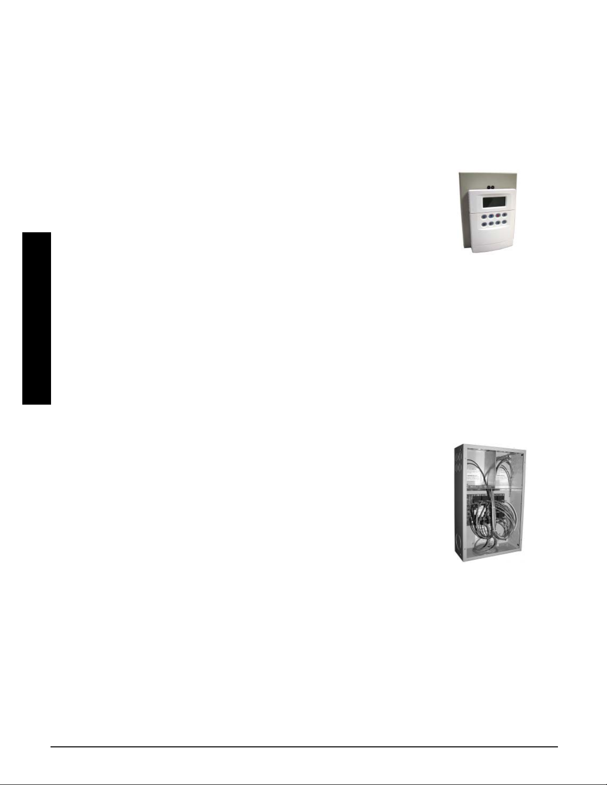
1. BACNet Control
Steffes commercial heating furnaces are available with a BACNet control
option. This device is easily integrated into most building automation systems to
provide building managers full control and visibility of the heating systems
operation. BACNet allows the following functions to be monitored with simple,
twisted pair communication:
· Real time system monitoring
· Full thermostat control
· Monitoring of heat storage levels in the brick and all system temperatures
· Remote configuration, testing and adjustment
· Service requirement alerts
2. On-Peak/Off-Peak Program
System responds to heat calls during the on-peak and off-peak periods; however, only energizes heating
elements during the off-peak periods. The Comfort Plus Commercial system is controlled by an external
control device such as a meter or time clock module.
Accessories
3. 4-20 Milliamp Control (1-5 volt DC)
System receives a signal from an external load control device such as a building load management system.
This external signal dictates the maximum amount of energy which can be consumed during a preset time
interval.
Order Item #1301015
BACNET
4. Pulse Monitoring
a) System monitors pulse outputs from the power company's electric meter.
Program parameters such as desired maximum building kW and pulse
ratios for the metering system being used are entered into the Comfort
Plus Commercial system. The system then charges proportionally when
demand free power is available. This keeps the total building kW usage at
or below the desired level.
b) External load management control modules are available when using pulse
monitoring load control. Each module has eight (8) zones which can be
controlled. The system must be configured to recognize the number of load
management modules installed (maximum of two per system).
LOAD MANAGEMENT
CONTROL MODULE
Order Item #1908140
Optional Accessories n 2.03 Comfort Plus Commercial Hydronic
Page 11
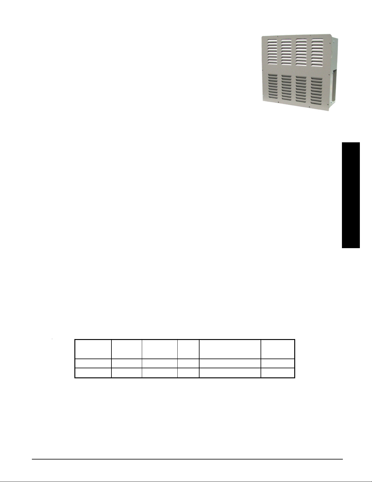
SCR CONTROLLER
The Steffes SCR (Solid State Relay Panel) is an optional control device used with
the Steffes ThermElect (8100 and 9100 Series) and Comfort Plus Commercial
(6100 and 7100 Series) Heating Systems. It utilizes SCR technology to enable
more precise balancing of a buildings overall electric load by varying the amount
of total element input that can be energized in a Steffes furnace at any given time
in relation to the maximum allowable building load. The Steffes SCR optimizes a
buildings power quality and control.
The SCR Controller can only accept input signals from the Steffes furnace but it
can respond to all types of control inputs to include 4 20 Milliamp, 1 5 Volt
DC, electric meter pulsing, Bacnet or any building energy management system.
With the 4 20mA or 1 5 volt DC signals, the SCR will provide an output
directly proportional to the input signal. 4mA signal produces 0% output while 20mA signal products 100%
output. With the utility pulse meter input, the SCR output percentage will automatically adjust to maintain a total
maximum system load as dictated by the furnaces set-up. With a Bacnet, the furnace can be commanded to
varying input levels remotely.
SCR CONTROLLER
Order Item #1301016
EXTERNAL DUCT SENSOR
The optional external duct sensor (Order Item #1041536) provides the ability to monitor the duct temperature at
an area beyond fresh air makeup and/or beyond other devices and regulate the discharge air temperature
accordingly.
The duct sensor feature is enabled if the 4 bit is set in Location 53 (L053). Once enabled, the Comfort Plus
Commercial Hydronic system monitors temperature at both the duct sensor and the output sensor during Y, W,
or E calls from the thermostat.
If there is a Y and a G call from the thermostat, the system operates the core blowers at the required speed to
maintain the minimum output temperature as set in Location 48 (L048) at the duct sensor. If there is only one
call from Y, W, or E, then the system will operate the core blowers at the required speed to maintain the
maximum output temperature as set in Location 49 (L049) at the duct sensor. The system is set to turn off the
core blowers if the output temperature at the output sensor exceeds 150 degrees Fahrenheit.
CONTROL CIRCUIT STEP-DOWN TRANSFORMER
The internal controls and motors of all Comfort Plus Commercial Hydronic systems operate at 240 volts (two
wire). In systems with 277/480 or 347/600 volt element circuits, a transformer must be installed per the installation instructions to supply this voltage to the systems controls. This transformer can be purchased as an optional
device from Steffes Corporation or sourced from your local electrical supply outlet. See the matrix below for
proper sizing.
Model
277/480V
347/600V
Primary
Voltage
480 240 2 HS1F1BS or equal 1017082
600 240 2 HS10F2AS or equal 1017080
Secondary
Voltage
KVA
Hevi Duty Item #
Steffes
Item #
Accessories
Comfort Plus Commercial Hydronic Optional Accessories n 2.04
Page 12
3
Installation
CAUTION
Risk of sharp edges. Can cause personal injury. Use caution
when installing and/or servicing equipment.
SHIPPING AND PACKAGING
The Comfort Plus Commercial Hydronic should always be transported in an upright position to avoid damage to
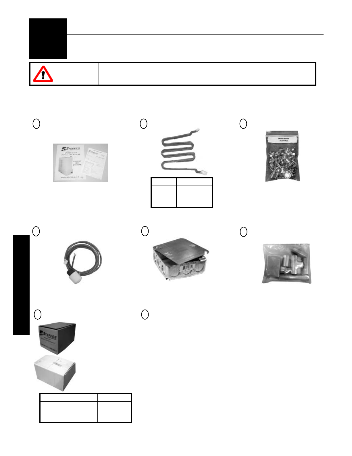
internal components and insulation materials. The information below describes the items shipped with each system:
INFORMATION PACKAGE
1
(includes Owner's Manual and
Warranty Registration Card)
(adhered to outer side of
shipping box)
OUTDOOR
4
TEMPERATURE SENSOR
HEATING ELEMENTS
2
MODEL ELEMENTS
7120 8
7130 12
7140 16
(shipped inside the brick core)
Refer to Pages 3.04-3.05
JUNCTION BOX
5
ELEMENT SCREW KIT
3
(shipped inside the
electrical compartment)
Refer to Pages 3.04-3.05
PRESSURE RELIEF
6
VALVE KIT
(shipped inside the electrical
compartment)
Installation
7 8
Installation n 3.01 Comfort Plus Commercial Hydronic
Refer to Pages 3.08
CERAMIC BRICK
Full Brick
(shipped separately and
packaged 4 brick per box)
Half Brick
(shipped with brick and
packaged in a white box
consisting of 6 half brick
and 1 full brick)
Model Full Brick Half Brick
7120 26 Boxes 1 Box
7130 37 Boxes 2 Boxes
7140 49 Boxes 2 Boxes
See Figure 4, Page 3.04
(shipped behind the
exchanger access panel)
See Figure 10, Page 3.07
TRANSFORMER
WIRING HARNESS
(shipped in electrical panel)
(277V & 347V
SYSTEMS ONLY)
(shipped behind the
exchanger access panel)
Refer to Page 3.11
Page 13
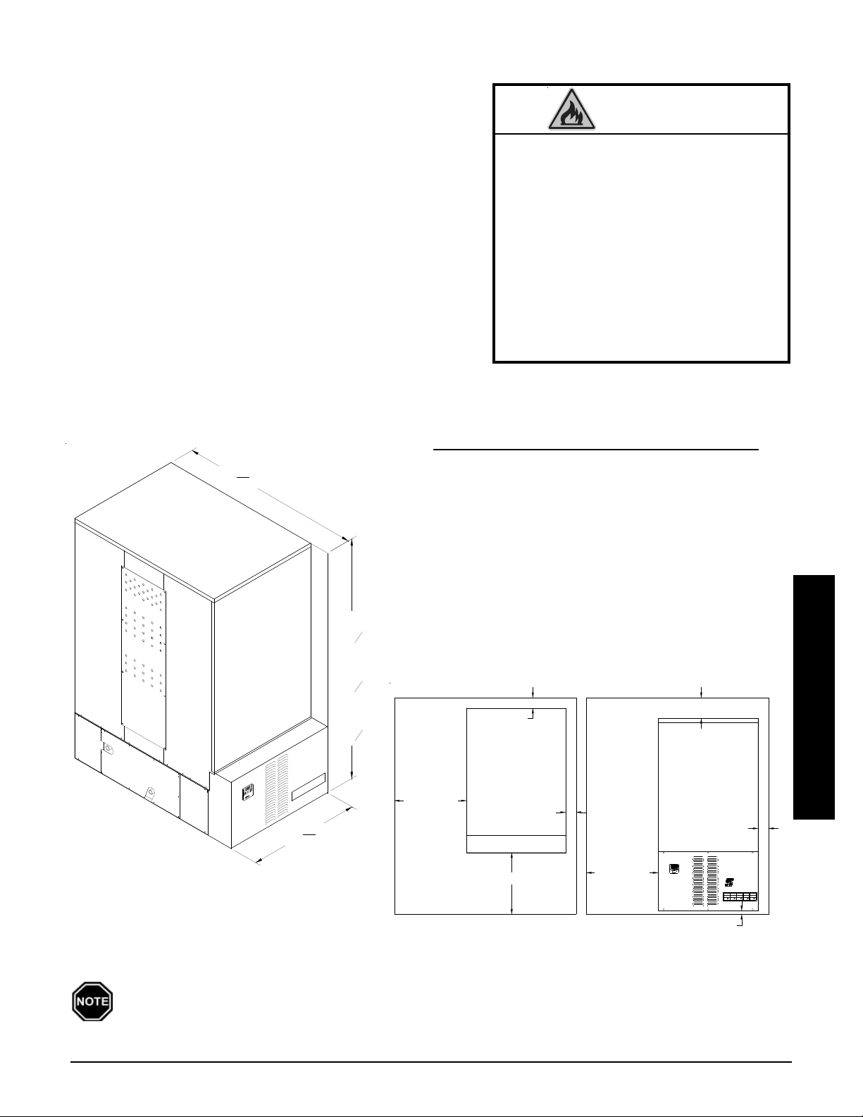
PLACEMENT AND CLEARANCE REQUIREMENTS
The physical dimensions (Figure 2) of the Comfort Plus Commercial Hydronic system along with the clearances required
(Figure 3) MUST be taken into consideration when choosing its
location within a structure. The best installation location for this
system is in a space requiring heat, so some amount of the
heating requirements can be satisfied through static dissipation
from the warm outer panels of the system. Standby heat dissipation of up to 2.5kW can be experienced in normal operation.
The minimum area required for the installation is 100 square feet.
This area must remain free of debris and room air should be
maintained at less than 85° Fahrenheit. If the system is being
installed in an area with less than 400 square feet, ventilation
MUST be provided. If less than 100 square feet, thermostatically controlled ventilation MUST be provided.
MODEL 7100 DIMENSIONS
FIGURE 2
MINIMUM CLEARANCE REQUIREMENTS
Risk of fire. Can cause injury or death.
w Violation of the clearance require-
ments or failure to provide proper
ventilation can cause improper
operation of the system. Maintain
the placement and clearance
requirements as specified and
provide ventilation as necessary.
w Moving the system after install
may result in equipment damage.
Do NOT move system from original installed location.
WARNING
47
16
5
"
w Back and Right Side = 3 inches (from combustible material)
w Bottom = 1 inch clearance
w Top = 6 inches (from combustible material)
w Front = 36 inches (for ease in servicing)
w Left Side = 36 inches (for ease in servicing)
7140
Front View
O
u
t
l
e
t
I
n
le
t
3
29
16
5
"
68
7130
57
7120
46
8
5
"
8
5
"
8
MODEL 7100 REQUIRED CLEARANCES
FIGURE 3
3" REQUIRED
CLEARANCE
6" REQUIRED CLEARANCE
Installation
TOP VIEW
FRONT VIEW
36" REQUIRED
CLEARANCE
"
36" REQUIRED CLEARANCE
3" REQUIRED
CLEARANCE
36" REQUIRED
CLEARANCE
A
M
P
M
STEFFES
M
3" REQUIRED
CLEARANCE
TEFFES
S
ELECTRIC THERMAL STORAGE
1" REQUIRED
CLEARANCE
Minimum clearance requirements do NOT account for space needed for making electrical connections. If utilizing, the Air Handler, an additional 24-27 inches is required on the right hand
side of the system.
Comfort Plus Commercial Hydronic Installation n 3.02
Page 14
If the Comfort Plus Commercial Hydronic is installed in an area where radiant heat coming from the system is
undesired or where room temperatures may reach 85° Fahrenheit or greater, it is strongly recommended to install
a Static Heat Recovery unit or Air Handler. Refer to pages 2.01-2.02 for information on these options.
In addition to the physical space requirements, the weight of the Comfort Plus Commercial Hydronic must be
taken into consideration when selecting the installation surface. A level concrete floor is the best installation
surface, but most well supported surfaces are acceptable. If unsure of floor load capacity, consult a building
contractor or architect.
Special requirements need to be considered if placing the system in a garage or other area
where combustible vapors may be present. Consult local, state, and national codes and regulations to ensure proper installation. An 18" stand (Order Item #1301585) is available to elevate
the system.
INITIAL SET-UP
Step 1 Remove the Information Package from the outside of
the shipping box and unpackage the Comfort Plus
Commercial Hydronic heating system.
Step 2 Move the heating system into its installation location.
To ensure proper operation, read and
follow installation instructions carefully.
w DO NOT install the Comfort Plus
The Comfort Plus Commercial Hydronic is capable of
fitting through a 30" doorway (minimum) without
disassembling. If it is necessary to disassemble the
system, refer to the disassembly instructions (Page
w DO NOT extend the leveling legs
w DO use and follow generally
A.03) in this manual.
Step 3 Once in place, adjust the leveling legs on the bottom of
the system as necessary to prevent rocking. If not
w DO have equipment installed by a
placed properly the system may bend or twist during the
brick loading process, making element and brick core
temperature sensor installation difficult.
Step 4 Remove the painted front panel of the brick storage
cabinet by removing the sheet metal screws along the top, bottom, and sides of the panel. Detach by
pulling the bottom of the panel forward and down.
Step 5 Locate the element wiring harnesses and the two brick core temperature sensors behind the front panel
and disconnect them from their shipping position. Carefully position them to avoid damage during brick
loading.
Step 6 Remove the galvanized front panel and set it aside.
Step 7 Carefully lift the two insulation blankets, one at a time starting at the bottom, and drape them over the
Installation
top of the system.
IMPORTANT
Commercial Hydronic system on its
shipping pallet.
more than one inch.
accepted safety practices when
handling insulation material.
qualified technician in compliance
with all applicable codes and
regulations.
Use face mask, gloves, and long sleeved garments when handling insulation materials in compliance with generally accepted safety practices.
Step 8 Remove the front air channel by pulling out at the top.
Step 9 Remove the heating elements from inside the brick core cavity.
Installation n 3.03 Comfort Plus Commercial Hydronic
Page 15
BRICK LOADING
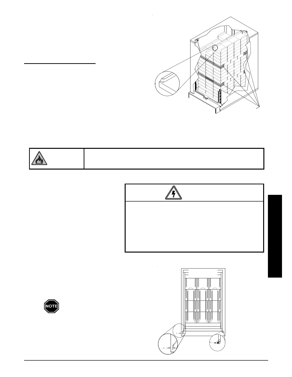
Load the brick, one row at a time, using a left side, right side,
center pattern. Start at the back of the brick core and work
forward. Make sure the brick are placed so the grooved
side is facing up, the notch is facing forward, and the ridges
are on the left and right. (See Figure 4.)
BRICK INSTALLATION TIPS:
Install bricks carefully to avoid damage to the
insulation panels.
Remove loose brick debris to prevent uneven
stacking of brick, as this can make installation of the
elements and the brick core temperature sensor(s)
difficult.
Brick rows MUST line up front to back and side to
side.
Half brick makes brick loading easier by evening out
the stacks. Use HALF BRICK (white boxes) in the
proper rows and positions as indicated in Figure 4. The back half of the brick MUST be installed in the
back row and the front half (the notched brick piece) MUST be installed in the front row.
Risk of fire. Can cause personal injury or death. DO NOT operate the Comfort
WARNING
Plus Commercial Hydronic system if damage to the insulation panels on the
inner sides of the brick core occurs.
BRICK LOADING
FIGURE 4
Notch in Brick
F
r
o
n
t
o
f
U
n
i
t
HALF BRICK
7120: Load in row 5
7130: Load in row 4 and 8
7140: Load in row 6 and 12
HEATING ELEMENT AND AIR CHANNEL INSTALLATION
Step 1 After all brick are loaded, insert the
heating elements between the brick
layers, sliding them in until the
element ends embed into the side
cutouts of the brick cavity.
The elements MUST be installed so
their threaded screw tabs on the
wire connection terminals point
forward and down. If they are
installed with the screw tabs
HAZARDOUS VOLTAGE: Risk of electric shock. Can cause
injury or death.
w DO NOT remove the electrical panel cover while
system is energized.
w Position elements properly to avoid short circuiting
them against metal surfaces.
w Protect element lead wires from front panel screws and
any field installed screws to avoid short circuit.
pointing upward, element-to-wiring
harness connections will be difficult. Elements
must be slid into the brick core properly to ensure
correct clearance between the terminal connections and any surfaces within the system. Refer to
the required element connection clearance information in Figure 5.
In the 277/347 Comfort Plus Commercial Hydronic systems, the sixth
element position up from the bottom
of the furnace is left open.
ELEMENT INSTALLATION
WARNING
FIGURE 5
TOP VIEW
Installation
3
Step 2 Install the front air channel with the air deflectors
(arrow shaped pieces) facing inward and with the
narrow ends of the deflectors pointing up. Place
bottom portion in first (Figure 6).
Comfort Plus Commercial Hydronic Installation n 3.04
"
4
3
"
4
Required Clearance Between
Element Termination and Metal
Panels is 1/2" (3/4" Nom inal)
Element Con n ec tio n
Page 16
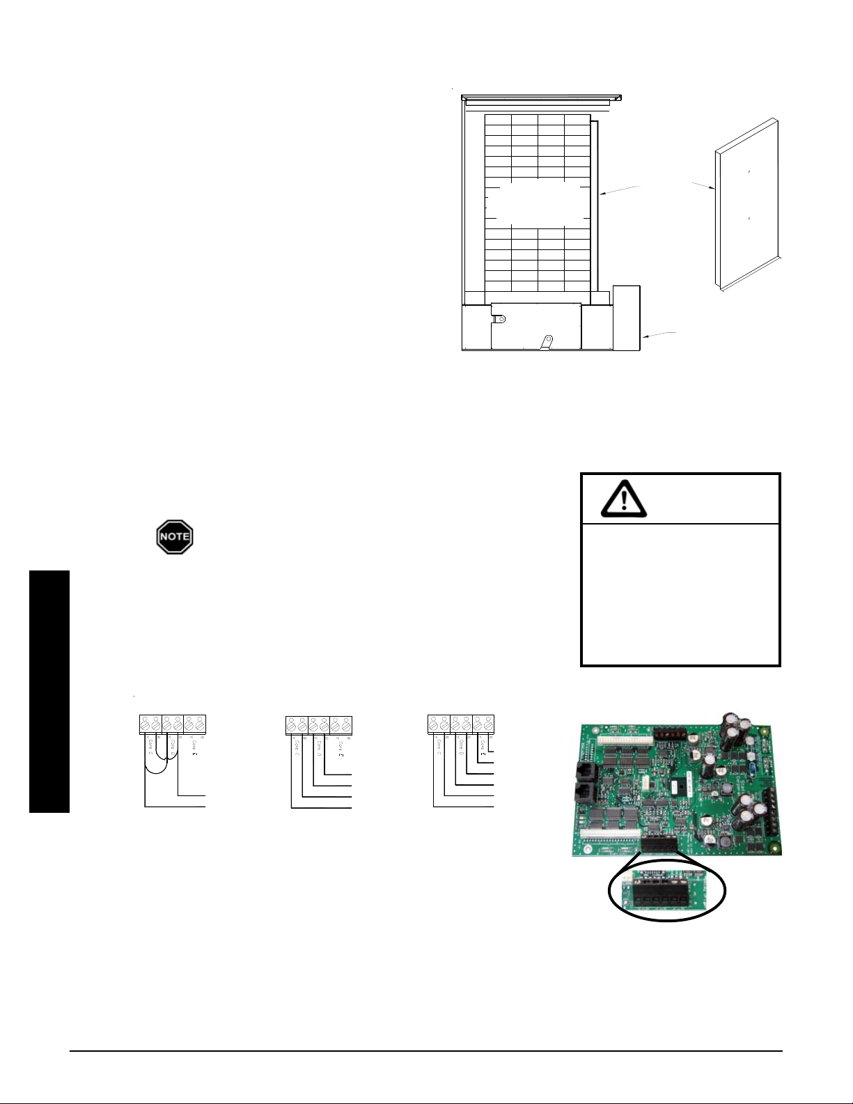
Step 3 Lower the insulation blankets back into position,
one at a time. Carefully tuck the sides of the
insulation into the edges, corners, and around the
AIR CHANNEL PLACEMENT
FIGURE 6
exposed portions of the heating elements to
ensure maximum efficiency.
Step 4 Reinstall the galvanized front panel and secure it
to the system using the screws that were originally removed. Slide the bottom of this panel
inside the lower lip of the brick cavity. The top
BRICK
CORE
SIDE VIEW
Front Air
Channel
rests on the outside of the cavity.
Step 5 Remove the electrical panel cover and locate the
element screw kit.
Step 6 Carefully route wiring harnesses and connect
them to the heating elements, using screws
provided in the hardware package. Make con-
Outlet
Inlet
Electrical
Panel
nections with screw heads up and threads
pointing down. Element screws should be tightened to 20 inch lbs. Refer to Element Installation (Figure
5) for proper positioning.
Step 7 The brick core temperature sensor must be installed prior to putting the painted front panel in place.
BRICK CORE TEMPERATURE SENSOR INSTALLATION
Step 1 Remove the screws by the brick core temperature sensor holes in the
galvanized front panel.
CAUTION
Model 7120 has one brick core temperature sensor
and Models 7130 and 7140 each have an upper and a
lower brick core temperature sensor.
Step 2 Insert the brick core temperature sensors through the holes in the
galvanized front panel. Be sure the sensor(s) are connected to the
relay driver board (Figure 7) as shown below. The sensor must pass
through the blanket insulation and into the brick core. Holes have not
been predrilled through the insulation. Use the sensor(s) to aid in
making a passageway by rotating them side-to-side while gently pushing inward.
7120
7130
7140
Installation
} Upper Core
} Lower Core
} Lower Core
Step 3 Once the brick core sensor(s) are installed, put the screws back
into position in the galvanized front panel to hold the sensors in
position and to provide the electrical ground.
Step 4 Check the non-insulated element terminations to make sure they do
not come within 1/2" of any surface area on the system.
Risk of improper operation.
Proper installation of the
brick core temperature
sensor is critical to the
operation of the heating
system. Read and follow
installation instructions
carefully.
FIGURE 7
} Upper Core
} Middle Core
} Lower Core
Step 5 Re-install painted front panel using previously removed screws.
Installation n 3.05 Comfort Plus Commercial Hydronic
Page 17
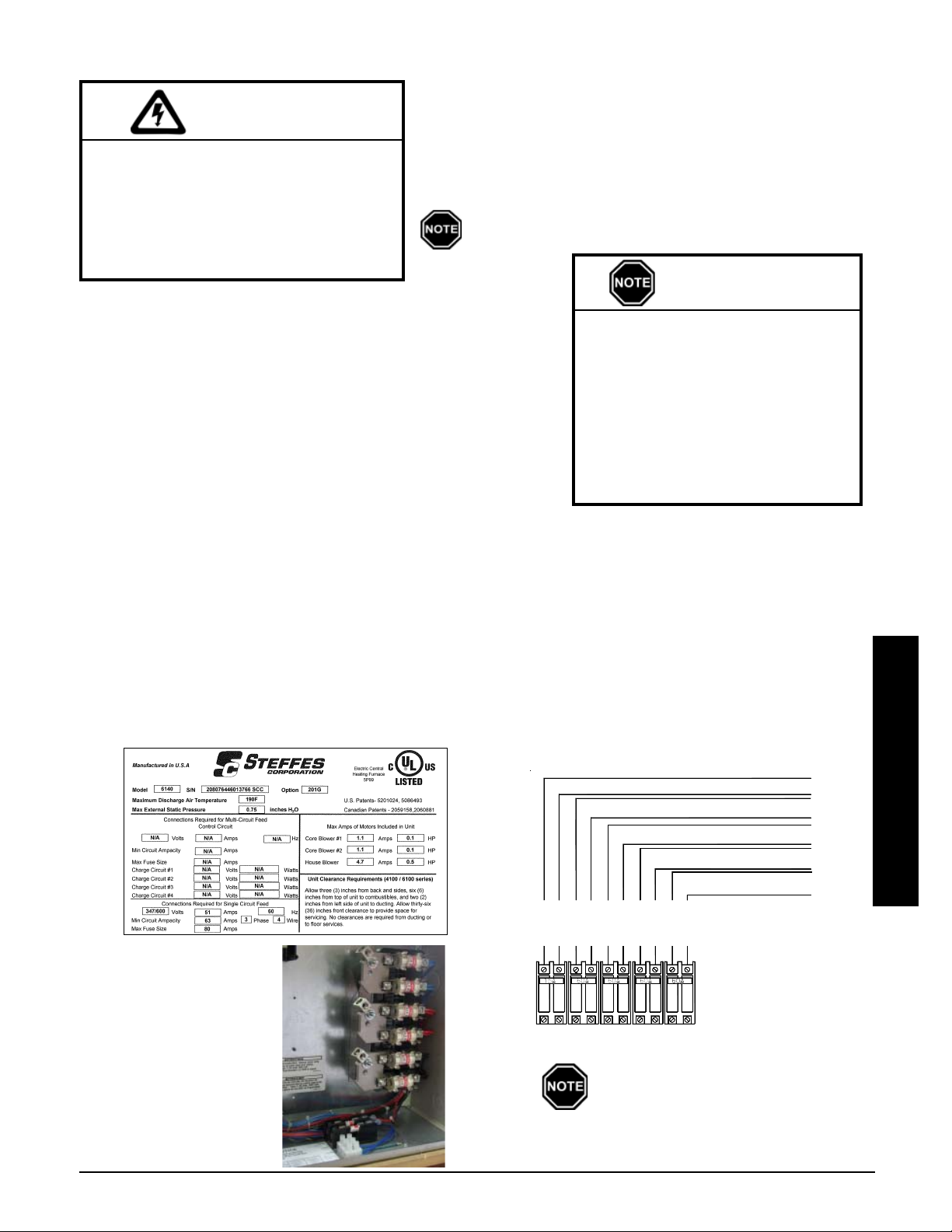
LINE VOLTAGE ELECTRICAL CONNECTIONS
In standard configuration, the system is wired for connection to
WARNING
HAZARDOUS VOLTAGE: Risk of electric
shock. Can cause injury or death. Do not
energize the system until installation is
complete. Equipment MUST be installed
by a qualified technician in compliance
with all applicable local, state, and
national codes and regulations.
240V; however, the element circuits can also be connected to
208V. A 208V connection derates the charging input of the
system by 25%. If a system rated specifically for 208V is
required, contact the factory. The controls circuit in the system
MUST be connected to 240V/208V.
277/480V and 347/600V Comfort Plus Commercial
systems are configured to use single feed only.
IMPORTANT
208/240V System Connections Only: The 60 amp breakers located
in the electrical compartment feed the core charging (element) circuits. The 15 amp breaker feeds the controls and blowers circuit. All
240V/208V systems are factory configured to be field connected to
multiple line voltage circuits. If a single feed line voltage circuit is
desired, an optional single feed kit is available from the factory.
277/480V and 347/600V System Connections Only: The fuse
block connection points and neutral connection block, located in the
line voltage side of the electrical compartment, feed the core charging
(heating element) circuits. This also provides power and the terminal
block connections for the primary side of the optional control voltage step-down transformer. Adjacent to these
terminals are the connection points for the transformer secondary. See Figure 9B.
w To ensure proper operation and
safety, all line voltage circuits
must be segregated from low
voltage wiring in the system.
w To reduce electro magnetic fields
associated with electrical circuits
and to avoid induced voltage on
sensors and electronic devices,
the circuit phases MUST be alternated as shown in Figure 9A.
To determine the correct wire size required for each circuit feeding the system, refer to the Specifications (Page
A.01-A.02) and the system's identification label located on the lower left side of the system. (Reference Sample
Label Figure 8.)
Step 1 Route all line voltage wires through a knockout and into the electrical panel.
Step 2 Make proper field wiring connections to the Comfort Plus Commercial system. Refer to the Line Volt-
age Wiring Diagrams (Pages A.04 - A.09) for more information on these connections.
SAMPLE SYSTEM IDENTIFICATION LABEL
FIGURE 8
CIRCUIT PHASING CONNECTIONS
208/240 SINGLE PHASE
FIGURE 9A
BLOWERS/CONTROLS CIRCUIT
CHARGE CIRCUIT #1
CHARGE CIRCUIT #2
CHARGE CIRCUIT #3
CHARGE CIRCUIT #4
LINE 2
LINE 1
LINE 1
LINE 2
LINE 1
LINE 2
LINE 1
LINE 2
LINE 1
LINE 2
To Service (Breaker) Panel
277/480V AND
347/600V THREE
PHASE
FIGURE 9B
Circuit Breakers
Installation
The 60 AMP breakers are for internal
component protection only. Sizing of the
field wire and breaker size MUST be in
compliance with all applicable local,
state, and national codes and regulations.
Comfort Plus Commercial Hydronic Installation n 3.06
Page 18
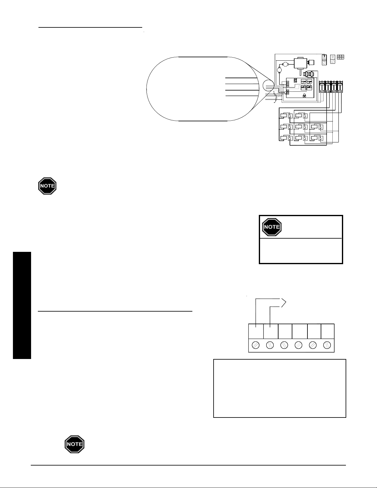
JUNCTION BOX INSTALLATION
LINE VOLTAGE WIRING DIAGRAM
Step 1 Attach the factory supplied
FIGURE 10
junction box to the left side
of the Comfort Plus Hydronic Commercial system
as shown in Figure 16
(Page 3.12).
Step 2 Make connections to the
Red & White To Primary
Loop Pump (Max 1.2 AMPS)
Black & White To Air Handler
Pump (Max 1.2 AMPS)
primary loop pump and air
handler pump inside this
junction box. The red and
These wires are located in the lower left
corner of the electrical compartment.
white wires connect to the
primary loop pump and the
black and white wires
connect to the air handler
pump. (See Figure 10.) The maximum connected amperage on either of these circuits is 1.2 amps.
Step 3 Attach the junction box cover using the screws provided.
If utilizing the optional air handler, the orange wire can be used with the white wire to power
a secondary pump for hydronic zones.
WHITE
OR
WHITE/BLACK
RED
BLACK
ORANGE
7120 Line Voltage
Wiring Diagram 208/240 Volt
Use copper or aluminum conductors rated at
75° C or higher for field connections of this device.
EXCHANGER
LIMITS
WHITE
OR
WHITE/BLACK
RED
BLACK
ORANGE
To Optional Air Handler
BLUE/WHITE
BLUE/BLACK
ORANGE
BLACK
To Optional Static
Heat Recovery System
225 °
BLACK/YELLOW
N.C.
BLUE
250 °
N.C.
MANUAL
RESET
AUTO
RESET
BASE IO BOARD
Element
#7
Element
#4
Element
#1
BLACK
WHITE
L1
L2 120
L2 240
BLOWER
RESISTOR
RESISTER
DAMPER
RED
BLACK/YELLOW
CORE BLOWER
HIGH
4uf
Cap.
COM.
5 Amp5 Amp
1/4 Amp1/4 Amp
Element
#8
Element
#5
Element
#2
CONTROL CIRCUIT
NEUTRAL LUG
TRANSFORMERS
240v / 24v
BLOWERS/
CIRCUIT
CIRCUIT #1
CONTROLS
COMCOM
COMCOM
NONO
NONO
NONO
COMCOM
PRIMARY
SHRU
LOOP PUMP
CHARGE
NONO
15A
60A
COMCOM
BLACK
Element
#6
Element
#3
GROUND
LUGS
CIRCUIT #2
CIRCUIT #3
CHARGE
CHARGE
60A
60A
RED
BLUE
LOW VOLTAGE ELECTRICAL CONNECTIONS - PEAK CONTROL
Steffes ETS heating equipment may be controlled by the Power Company via a
peak control signal. This signal can be sent to the equipment using a Steffes
Power Line Carrier control system, low voltage wiring, a Steffes Time Clock
Module, or line voltage control. In applications utilizing automatic charge control,
outdoor temperature information is required and can be received via an outdoor
sensor or power line carrier control system.
The Comfort Plus Commercial Hydronic system is factory configured for
low voltage peak control and is set to charge when the utility peak control
switch closes. Refer to the Configuration Menu (Pages 3.14-3.15) for
information on configuring the system for the application.
LOW VOLTAGE (HARD WIRED) PEAK CONTROL
If using the low voltage peak control option, the Comfort Plus Commercial
Installation
Hydronic is direct wired to the power company's peak control switch. Field
connections from the peak control switch are made to the low voltage
terminal block through a low voltage knockout located on the left side of the
electrical panel.
Step 1 Route a low voltage circuit from the power
companys load control or peak signaling device to
6-Position Low Voltage Terminal Block Coding
RP = Peak Control Input Common
the six (6) position low voltage terminal block inside
the electrical compartment of the Comfort Plus
Commercial Hydronic system through one of its low
voltage wire knockouts.
AP = Anticipated Peak (Pre-Peak) Control Input
COM = Peak Control Output Common
NC = Peak Control Output (Normally Closed)
NO = Peak Control Output (Normally Open)
Step 2 Connect the field wiring to positions "RP" and "P" on
the six (6) position low voltage terminal block. (See Figure 11.)
Low voltage wires
MUST never enter any
line voltage enclosure.
TERMINAL CONNECTIONS
RP
P = Peak Control Input
IMPORTANT
PEAK CONTROL
FIGURE 11
To Dry Contact Peak
Control Switch
AP
COM
NCP
NO
To use the Comfort Plus to control other loads, refer to Auxiliary Load Control (Page
3.13).
Installation n 3.07 Comfort Plus Commercial Hydronic
Page 19
POWER LINE CARRIER (PLC) PEAK CONTROL
The Steffes Power Line Carrier (PLC) control system has the ability to communicate with the Comfort Plus
Commercial Hydronic system through the existing electrical circuits in the structure. With the power line carrier
option, hard wired low voltage connections from the power company's peak signaling switch connect directly to
the transmitting device. The switch signals peak control times to the transmitter, the transmitter sends the signals
to the Comfort Plus Commercial Hydronic system, which receives this information and responds accordingly.
In addition to providing peak control signals, the transmitter also provides outdoor temperature information for
automatic charge control, room temperature set back, and anticipated peak utility control signals (if applicable).
The PLC control is optional and must be ordered separately. If utilizing a PLC system, refer to the owner's
manual for information on the installation and operation of the PLC control system.
TIME CLOCK MODULE PEAK CONTROL
The Steffes Time Clock Module is another option for providing a peak control signal to the Comfort Plus Commercial Hydronic. It mounts inside the systems low voltage electrical compartment and interfaces with the
relay board via an interface cable. Peak control times must be programmed into the system once the module is
installed to enable the time clock feature. Refer to the instructions provided with the Time Clock Module for
more information on the installation and operation of this device.
LINE VOLTAGE PEAK CONTROL
Line voltage control is also an option, but is not the preferred method of control as it is usually more complex and
expensive. If line voltage control is utilized, the controls circuit must be powered with an uninterrupted circuit.
An external switching device, such as a relay panel, is necessary to directly control the heating element charging
circuits. If relying on this method of control, the faceplate on the system MUST continuously display a brick
core operating mode of C (charge) regardless of whether it is an off-peak or on-peak period.
LOW VOLTAGE ELECTRICAL CONNECTIONS - OUTDOOR
TEMPERATURE SENSOR (OPTIONAL)
The outdoor sensor monitors outdoor temperature and provides this
information to the system. The system responds by automatically storing
heat in its brick core according to outdoor temperature and heating
requirements.
Installation Methods: Hard wired to system to the "OS" and "SC"
terminals (default) OR connected to Power
Line Carrier (PLC)
Location of: Must be placed in a location where it can accurately sense
outdoor temperature and is not affected by direct sunlight
w If connecting to a Steffes PLC
system, follow the installation
instructions in the PLC system's
Owner's and Installer's Guide.
w Outdoor sensor wire MUST
NEVER be combined with other
control wiring in a multiconductor cable.
or other abnormal temperature conditions.
Wiring: · Route low voltage wire from the outdoor sensor to the electrical compartment through one of the low
voltage wire knockouts.
· Connect to "OS" and "SC" as shown in Figure 12 or to the two outdoor terminals as shown in Figures
13-15.
· If sensor wiring is routed through an external wall, the opening through which the wire is routed
MUST be sealed. Failure to do so may affect the accuracy of the sensor.
· The outdoor sensor is supplied with a lead length of 40 ft. If a greater wire length is needed, it can be
extended to a total of 250 ft.
· No other loads can be controlled or supplied through this cable. It is for connection of the outdoor
sensor ONLY.
· This low voltage cable MUST not enter any line voltage enclosure.
· Unshielded Class II (thermostat) wire can be used as extension wire provided it is segregated from
any line voltage cabling.
IMPORTANT
Installation
Comfort Plus Commercial Hydronic Installation n 3.08
Page 20
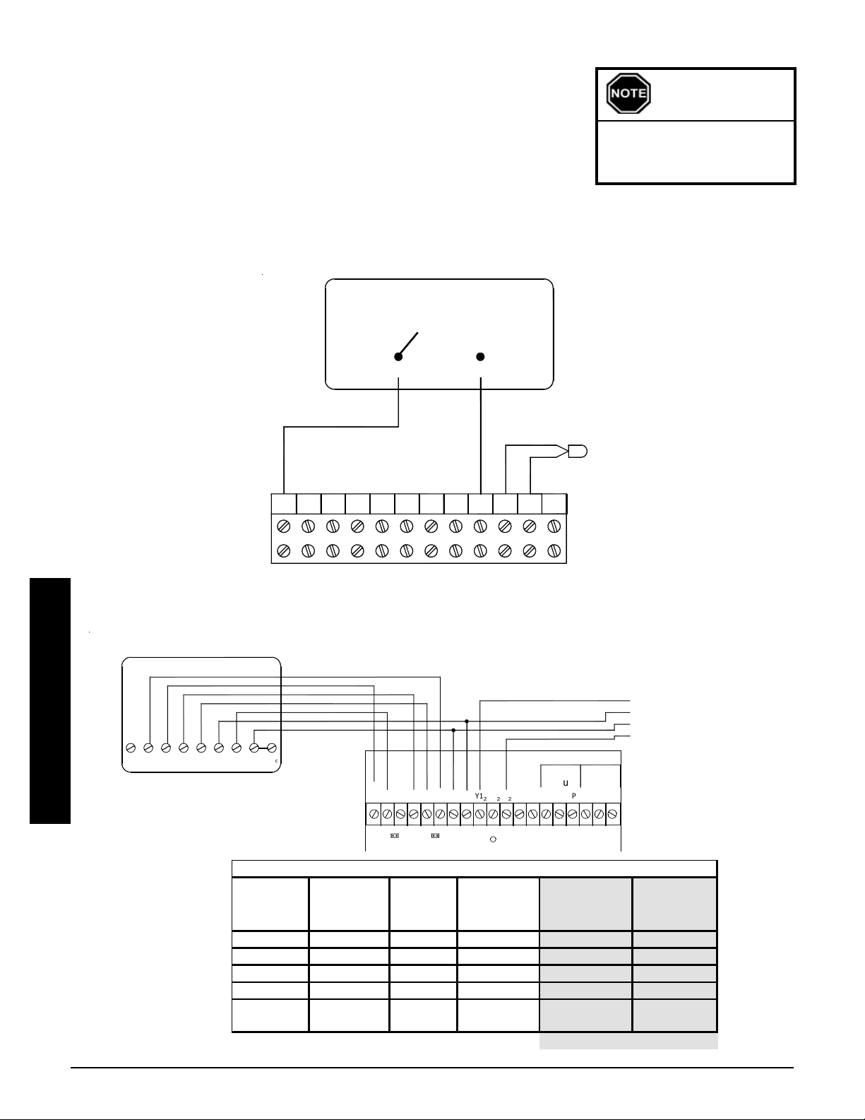
LOW VOLTAGE ELECTRICAL CONNECTIONS -
Dischar g e Air
Temperature
Hydronic
ROOM THERMOSTAT
A low voltage (24VAC) room thermostat may be used for room temperature
control with the Comfort Plus Commercial Hydronic system. Steffes recommends using a digital thermostat. If utilizing a mechanical thermostat, a load
resistor may be necessary due to the low current draw (.01 amps) on the heat
call input circuit of the system. Contact the factory for information on thermostats available from Steffes.
LOW VOLTAGE CONNECTIONS
HYDRONIC HEATING SINGLE ZONE SYSTEM
FIGURE 12
Hydronic Heat Thermostat, Zone
Valve End Switch, or Pump Control
IMPORTANT
Low voltage wires MUST
never enter any line
voltage enclosure.
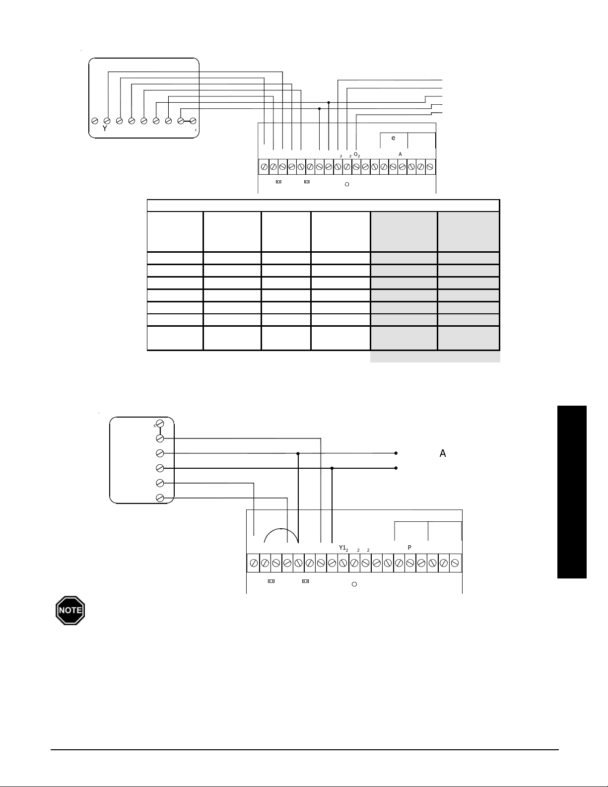
SINGLE STAGE HEAT PUMP APPLICATION WITH VARIABLE SPEED BLOWER
Installation
+$,-.
#
!*
'
)
IMPORTANT
Thermostat
Stage
1 Y1/G 1 100% HC1 L048
2 Aux/Y1/G 1 100% HC3 L049
Fan G 0 400 cfm HCF N/ A
Cool Y1/G/O 1 100% COOL N/A
R
R
CY OGO2HWOSDS
Y2
W
FIGURE 13
!%&
è
Thermostat
Output
#$
"
'
SINGL E STAG E HEAT PUM P
Heat
Pump
Stage
% of
Selected
CFM
SC
(
!((
Dig ital Di spl ay
(3
2
Heat Call
Status on
Outdoor Sensor
(
)$10
)$10
/01/
!*
+
Target
Installation n 3.09 Comfort Plus Commercial Hydronic
Heat Control
H/E N/A N/A HC3 N/A
*Contrac tor Us e Only
Page 21
TWO STAGE HEAT PUMP APPLICATION WITH VARIABLE SPEED BLOWER
Dischar ge Ai r
Temperature
Hydronic
FIGURE 14
)*"!!+,-#
(
%
IMPORTANT
0).!!
'
Thermostat
Stage
1 Y1/G 1 50% HC1 L048
2 Y1/Y2/G 2 100% HC1 L048
3 Aux/Y1/Y2/G 2 100% HC3 L049
Fan G 0 40 0 cfm HCF N/ A
Cool 1 Y1/ G/O 1 50% COOL N/A
Cool 2 Y1/Y2/G/O 2 100% COOL N/A
Thermostat
Output
è
#$
% &
&&
!"
TWO ST AG E HEAT PUM P
Heat
Pump
Stage
% of
Sele cted
CFM
&.3
2)
Heat Call
Status on
Digital Display
.&
./
./
'"1!./)
'"1!./
0)/1.!
(
!.*
Target
Heat Co n trol
H/E N/A N/A HC3 N/A
*Contractor Use Only
STAND ALONE FURNACE APPLICATION WITH VARIABLE SPEED BLOWER
CONNECTIONS SHOWN FOR SINGLE STAGE HEATING / SINGLE STAGE COOLING
(UNCONTROLLED AIR CONDITIONING)
"#
!
IMPORTANT
,$$-.$.+$/$%"+('
,$$-.$.+$/$%"+('
è
FIGURE 15
$%$
"%%"$
()
*"+
&'
(#
If installing a mechanical thermostat or thermostat with anticipator, a resistor kit is required
(Order Item #1190015).
Installation
AIR CONDITIONER/HEAT PUMP INTERFACE
The Comfort Plus Commercial Hydronic system can be used in conjunction with an air conditioner or a heat pump.
Refer to the optional Air Handler (Page 2.02) and the Low Voltage Connections for Heat Pump Application
Diagram (Figure 13-14), for more information on interfacing these systems with the Comfort Plus Commercial
Hydronic. If multiple heat pumps are being interfaced, contact Steffes Corporation.
Comfort Plus Commercial Hydronic Installation n 3.10
Page 22
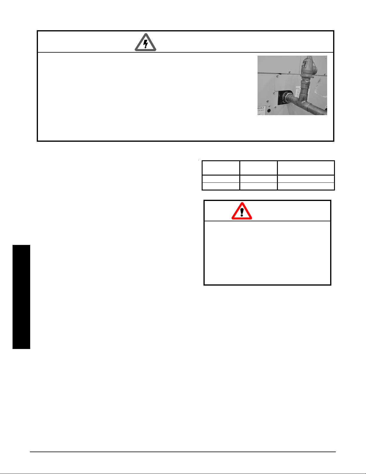
PRESSURE RELIEF VALVE INSTALLATION
WARNING
Risk of explosion. Can cause injury or death. The factory supplied
pressure relief valve MUST be connected to the system with the
supplied fittings.
w DO NOT modify this assembly.
w DO NOT cap, plug, or otherwise obstruct the outlet of the
pressure relief valve.
w DO mount the pressure relief valve in a vertical, upright
position.
w This pressure relief valve is sized to service the needs of the Comfort Plus Commercial
Hydronic heating system. If multiple heating systems are being used, pressure relief
valving for the other system MUST be provided separately.
Step 1 Remove the exchanger access panel and locate the pressure relief valve assembly.
Step 2 Connect the pressure relief valve to the outlet
water port on the left side of the Comfort Plus
Commercial Hydronic. It is extremely important
that the following conditions for installation of this
Pressure
Relief Valve
30 PSI 400,000 20 PSI
75 PSI 500,000 60 PSI
Minimum
BTU Rating
Maximum
Operating Pressure
part are met:
· Ensure all connections, including the valve
inlet are clean and free from any foreign
CAUTION
material.
· Use pipe compound sparingly, or tape on
external threads only.
· Mount the pressure relief valve in a vertical,
upright, position directly to the outlet water
port of the system. Under no circumstances
should there be a flow restriction or valve of
any type between the safety relief valve and
the pressure vessel.
Risk of discharged hot water and/or
steam. Can cause personal injury or
property damage. During operation,
the pressure relief valve may discharge large amounts of steam and/or
hot water. To reduce the potential for
bodily injury or property damage,
install a discharge line.
Step 3 Use schedule 40 pipe to install a discharge line for the pressure relief valve. This discharge line MUST:
· be connected from the valve outlet with no intervening valve and directed downward to a safe
Installation
point of discharge.
· allow complete drainage of both the valve and the discharge line.
· be independently supported and securely anchored to avoid applied stress on the valve.
· be as short and straight as possible.
· terminate freely to atmosphere where any discharge is clearly visible and is at no risk of freezing.
· terminate with a plain end that is not threaded.
· be constructed of a material suitable for exposure to temperatures of 375
o
F or greater.
· be, over its entire length, of a pipe size equal to or greater than that of the valve outlet.
PLUMBING
The Comfort Plus Commercial Hydronic heating system MUST be plumbed with a primary loop and
secondary (zone) loops. The primary loop needs to consist of a minimum of 10' of 1" pipe and requires its own
pump* (circulator). The secondary (zone) loops require additional pump(s) to operate effectively. Refer to Typical
Primary Loop (Figure 16) and the Typical System Plumbing Diagrams (Figures 17 and 18) for installation information.
The primary loop serves to regulate heat transfer from the systems heat exchanger, therefore, the primary loop must
be powered by Comfort Plus Commercial Hydronic control system.
Installation n 3.11 Comfort Plus Commercial Hydronic
Page 23
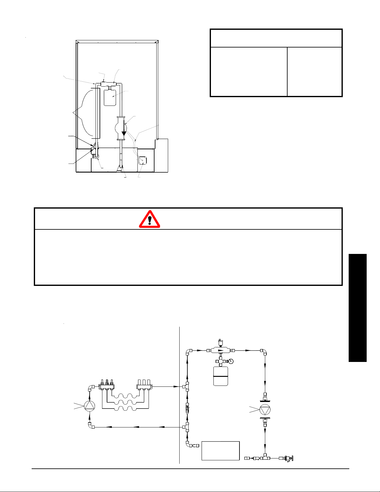
TYPICAL PRIMARY LOOP
FIGURE 16
PRESSURE DROP THROUGH
HEAT EXCHANGER
Piping MUST Be
Supported
Zone
Connection
Area
Pressure
Relief Valve
(Factory Supplied)
Optional
Temperature and
Pressure Relief Valve
(Consult Local Code)
Air Vent
Outlet
Air Separator
Inlet
Expansion
Tank
*Primary
Loop
Pump
Junction Box
(Factory Supplied)
Primary Loop Pump
Control Wiring
(White & Red)
CAUTION
STATIC PRESSURE
(Feet Water Column)
Based on 80 degree entry
water temperature with
a 50% glycol mix.
.1 ft @ 2 GPM
.2 ft @ 4 GPM
.4 ft @ 6 GPM
.7 ft @ 8 GPM
1.1 ft @ 10 GPM
PUMP SPECIFICATIONS
Steffes recommends a Grundfos UP15-42F
single speed 115VAC pump for the
primary pump.
Air Handler pump should NOT be a split
phase pump.
Air Handler pump should NOT have any
type of auxiliary control built into or onto
the pump.
FREEZE PROTECTION: Risk of frozen pipes. Can cause property damage. Hydronic heating system
freeze-ups WILL cause extensive damage to the entire heating system and/or property. It is the responsibility of the installer to provide protection against freezing.
PIPING SUPPORT: Risk of exchanger damage. Can cause property damage or personal injury. DO
NOT use the exchanger as support for piping. Support brackets should be in place to ensure proper
operation of the system and to keep pressure off the inlet and outlet piping.
TYPICAL SYSTEM PLUMBING
SINGLE TEMPERATURE ZONES
FIGURE 17
Primary Loop
This Valve Must
Be Open During
White
Red
Primary
Loop Pump
White
Red
Secondary Loop
Normal Operation
Installation
Exchanger
Comfort Plus Commercial Hydronic Installation n 3.12
Page 24
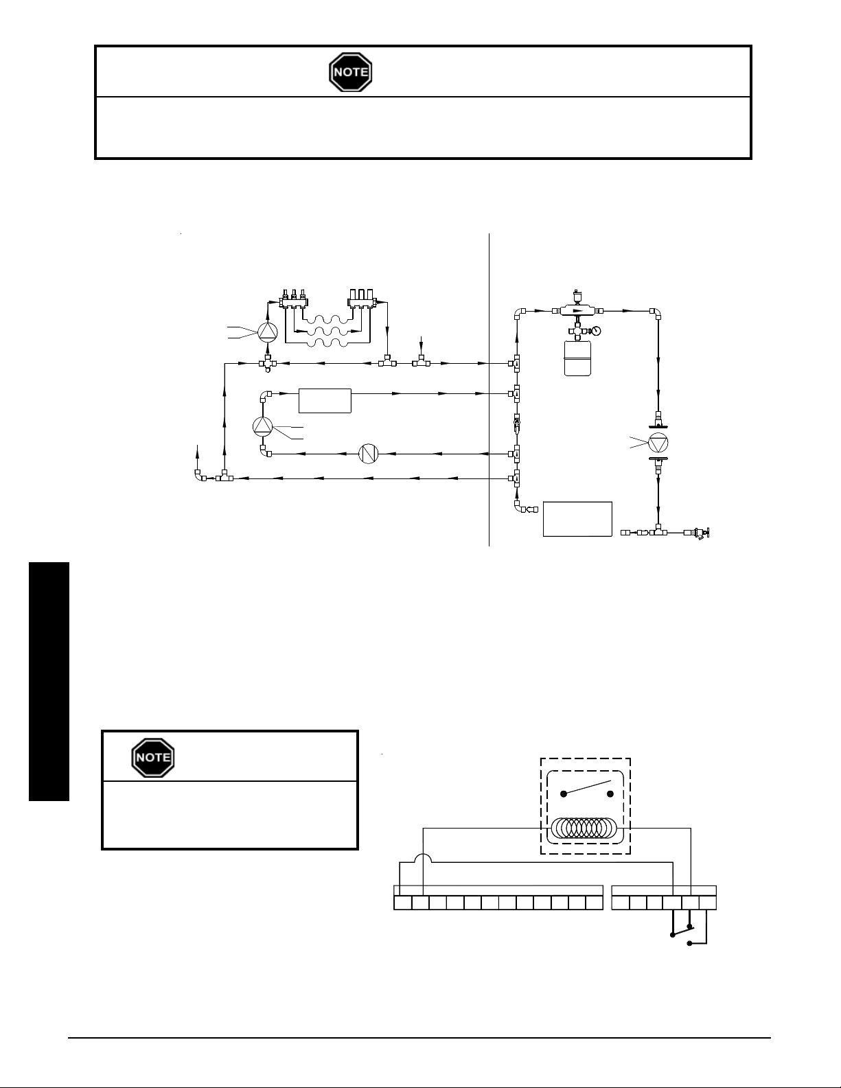
IMPORTANT
Secondary Loop
Primary Loop
It is the responsibility of the installer to prevent involuntary flow of water to the air handler. Not
doing so may cause limit tripping and/or decrease heat pump efficiency. Use of a check valve,
zone valve, or other device may help prevent involuntary flow.
TYPICAL SYSTEM PLUMBING
(SHOWN WITH STEFFES AIR HANDLER)
FIGURE 18
Low Temp Radiant Zones
From
White
Orange
Mixing
Valve
To
Other
Zones
-
-
+
5100 Air
Handler
White
Black
CHECK
VALVE
Other
Zones
This Valve Must
Be Open During
Normal Operation
White
Red
Primary
Loop Pump
High Temp
Water
Comfort +
Hydronic
Exchanger
AUXILIARY LOAD CONTROL
The Comfort Plus Commercial Hydronic system can be used to provide control signals to other loads in the
application. To do so, connect low voltage control wires to the "COM" and "NC" or the "COM" and "NO" positions of the six (6) position low voltage terminal block in the electrical compartment of the Comfort Plus Commercial Hydronic. (See Figure 19.) These contacts are rated for 30 volts, 3 amps maximum.
Installation
IMPORTANT
Maximum external load should
not exceed 60 VA on the system's
class II transformer.
TYPICAL AUXILIARY LOAD CONTROL
FIGURE 19
Auxiliary Control Relay
RELAY
Installation n 3.13 Comfort Plus Commercial Hydronic
W
O2 SC DS
RPYCR OGY2 OSH
COMAPP NONC
Internal
Peak Control
Output Relay
NOTE: During off-peak (charge) periods, the contact is
closed between "COM" and "NC".
Page 25
CONFIGURATION MENU
The Steffes Comfort Plus Commercial Hydronic heating system has a Configuration Menu, which allows the system to be customized to the power company and
consumers needs. This menu can be accessed on start-up and allows configuration settings to be easily adjusted.
To access the Configuration Menu:
Step 1 Energize the system. Access to the Configuration Menu is allowed
for the first two (2) minutes of operation. If the system has been
energized for more than two (2) minutes, the 15 amp circuit breaker
must be powered off and back on to gain access to this menu.
Step 2 Press and release the M button until the faceplate displays CONF.
IMPORTANT
If access to the Configuration Menu times
out, the 15 amp circuit
breaker must be powered off and back on
to re-enter the menu.
Step 3 Press the up arrow once and the faceplate will display C000.
The faceplate will flash between
C000 and the corresponding configuration value.
Step 4 If necessary, edit the configuration value by pressing and holding the M button while using the up or the
down arrow button to change the value.
Step 5 Once the value is correct, release the buttons and press the up arrow button to go to the next configura-
tion (C001,C002, etc.)
Step 6 Repeat steps 4 through 5 until all configuration settings have been adjusted to the desired values.
Step 7 Once configured, use the down arrow to leave the Configuration Menu.
In most applications only a few, if any, configuration changes will be necessary. Following is a description of the
configuration settings and their function:
C000 Off-Peak Method of Charge Control - Sets the method of brick core charging to be used during off-
peak (charge) periods. System is configured for automatic charge control which is a value of five (5).
C001 Start Brick Core Charge Set Point - If utilizing automatic charge control as set in C000, this value
indicates the outdoor temperature at which the system will start charging.
C002 Full Brick Core Charge Set Point - If utilizing automatic charge control as set in C000, this value
indicates the outdoor temperature at which the system will target a full core charge.
C003 Power Line Carrier (PLC) Channel Selection - If using PLC communication, this setting must
match the channel setting in the Steffes PLC transmitting device. A value of zero indicates power line
carrier communication is disabled.
C004 Optional Controls Configuration
Value Configuration Description
8 No Outdoor Sensor/No Time Clock Module
9 Outdoor Sensor/No Time Clock Module
12 No Outdoor Sensor/Time Clock Module
13 Outdoor Sensor/Time Clock Module
C005 Control Switch Configuration If utilizing power line carrier control, the Steffes Time Clock Mod-
ule, line voltage peak control, or if the utility control switch opens for charging this value should be zero
(0). For all other applications, this value should be one (1).
Configuration Menu continued on next page...
Comfort Plus Commercial Hydronic Installation n 3.14
Installation
Page 26
C006 Output Control Configuration - Configures the output controls of the Comfort Plus Commercial
Hydronic system. To determine the value, check the options desired from the list below. Then, add the
numbers from the Value column and enter the sum into this location. If not used in conjunction with a
heat pump or air conditioner, the value in this location should be set to two (2).
Value Option Selected
2 Comfort Plus Commercial Hydronic System (Model 7140 )
8 Enables compressor control if there is a "COOL" call during a peak (control) time.
32 If it is a peak (control) period and the Comfort Plus Commercial Hydronic receives a
cooling call, the compressor will turn off and on in 20 minute intervals (off 20 minutes, on
20 minutes, off 20 minutes, etc.).
128 Interfaces Comfort Plus Commercial Hydronic with a heat pump that has a reversing
valve which is energized for heating.
C007 Charge Factor - This configuration should be set to a value of 30.
C008 through C010 configurations are only applicable if the Comfort Plus Commercial Hydronic system is being used in conjunc
tion with a heat pump.
C008 Heat Pump Compressor Outdoor Lock-Out Temperature for Off-Peak or Anticipated Peak
Modes - Indicates the outdoor temperature at which the heat pumps compressor is locked out and not
allowed to operate during an off-peak or anticipated peak period.
C009 Heat Pump Compressor Outdoor Lock-Out Temperature for On-Peak Mode - Indicates the
outdoor temperature at which the heat pumps compressor is locked out and not allowed to operate
during an on-peak period.
C010 Minimum Discharge Air Temperature - Sets the minimum discharge air temperature the system
targets during a Stage 1 heat call.
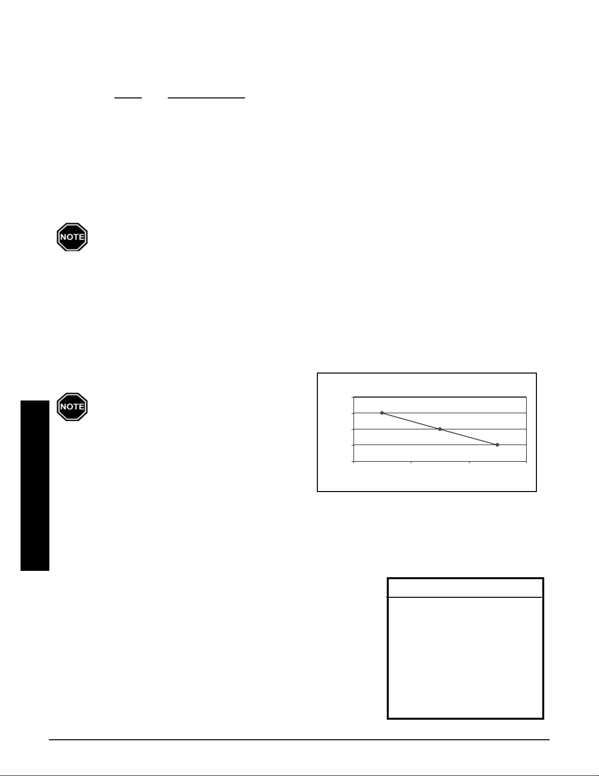
Example of O utdoor Reset
C011 and C012 configurations must be set
for the hottest temperature zone in the
installation. C011 is the highest temperature the system will target and C012 is the
lowest temperature the system will target
during a heat call. Outdoor reset is done
using these two temperatures. (See graph.)
200
180
160
140
Water Temp eratu r e
120
10 30 50
Outdoor Tempe rature
C011 Maximum Outlet Water Temperature - The value set indicates the maximum outlet water tempera-
Installation
ture to be targeted. The targeted outlet water temperature is affected by the values in C001 and C002.
For example, if the value in C001 = 50; C002 = 10; C011 = 180; C012 = 140, then at an outdoor temperature of 30 degrees, the targeted outlet water temperature would be 160 degrees.
C012 Minimum Outlet Water Temperature - The value set
indicates the minimum outlet water temperature to be targeted.
The targeted outlet water temperature is affected by the values
in C001 and C002. For example, if the value in C001 = 50;
C002 = 10; C011 = 180; C012 = 140, then at an outdoor temperature of 30 degrees, the targeted outlet water temperature
would be 160 degrees.
C013-C021 Time Clock Module Configuration - These configura-
tion settings are used to configure the peak control times
when utilizing the optional Steffes Time Clock Module.
Refer to the installation and configuration instructions
included with the module for more information.
Risk of high temperature
water. Can cause property
damage. Improper water
temperature settings can
result in damage to the floor
covering. Make sure the
maximum and minimum water
temperatures are appropriate for the application.
CAUTION
Installation n 3.15 Comfort Plus Commercial Hydronic
Page 27
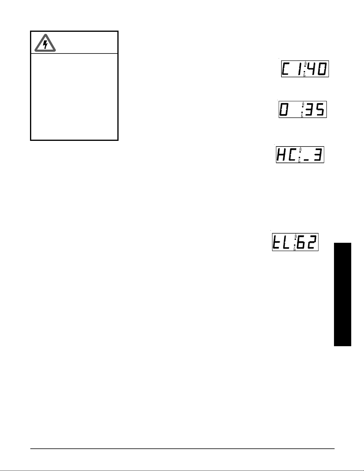
INSTALLER'S FINAL CHECK-OUT PROCEDURE
Step 1 Verify that the water pressure is correct for the application. The
WARNING
water pressure of the Comfort Plus Commercial Hydronic heating
system should be between 12 and 20 psig.
HAZARDOUS VOLTAGE:
Risk of electric shock.
Can cause injury or
death. System may be
connected to more than
one branch circuit.
Disconnect power to all
circuits before servicing.
Equipment must be
serviced by a qualified
technician.
Step 4 Press the up arrow again and the current heat call status will be displayed on the
control panel. Refer to the Operating Status section (Page 1.02) for more information on the heat call status display.
Step 5 Initiate a heat call from the room thermostat and verify that the Comfort Plus Commercial Hydronic
system recognizes the appropriate heat call. Refer to the Operating Status section (Page 1.02) for
information on the various heat call status displays. In applications utilizing the Air Handler, verify
that the Air Handler and/or heat pump operates appropriately.
Step 6 If utilizing the Air Handler, initiate a cooling call from the room thermostat and verify that the
Comfort Plus Commercial Hydronic system recognizes the COOL call. Verify that the Air
Handler, heat pump, and/or air conditioner operates appropriately.
Step 2 Verify that the operating mode displayed on the
control panel corresponds with the power
company's peak control signal. Refer to the
Operating Status section (Page 1.02) for more information on the
proper operating mode.
Step 3 Press the up arrow one time and verify that the
outdoor temperature information displayed on
the control panel is approximately the same as
the current outdoor temperature. Refer to the Operating Status
section (Page 1.02) for more information on the outdoor temperature
display.
Step 7 Press the up arrow until the targeted brick core charge level is displayed on the
control panel. With the system in an off-peak (charge) mode, initiate the charge
control override. Refer to the Charge Control Override section (Page 1.03) for
instructions on initiating the charge control override. Once initiated, the target level of the Comfort
Plus Commercial Hydronic should be 100 percent, the control panel should display tL: F, and all of
the heating elements should be energized.
Step 8 With an amp meter, verify that the amperage of the system is correct for the installation. Refer to
the System Identification Label on the Comfort Plus Commercial Hydronic system for information
regarding the proper amperage.
Step 9 Cancel the charge control override and verify that all elements in the system de-energize. Refer to
the Charge Control Override section (Page 1.03) for instructions on canceling the charge control
override.
Step 10 Verify that all hydronic heating zones are operating as intended.
Step 11 Verify, once again, that the Operating Mode displayed on the control panel corresponds with the
power company's peak control signal.
Step 12 In applications utilizing the Steffes Power Line Carrier control system, complete the Installers Final
Check-out Procedure in the Owners and Installers Manual provided with that device.
Installation
Comfort Plus Commercial Hydronic Installation n 3.16
Page 28
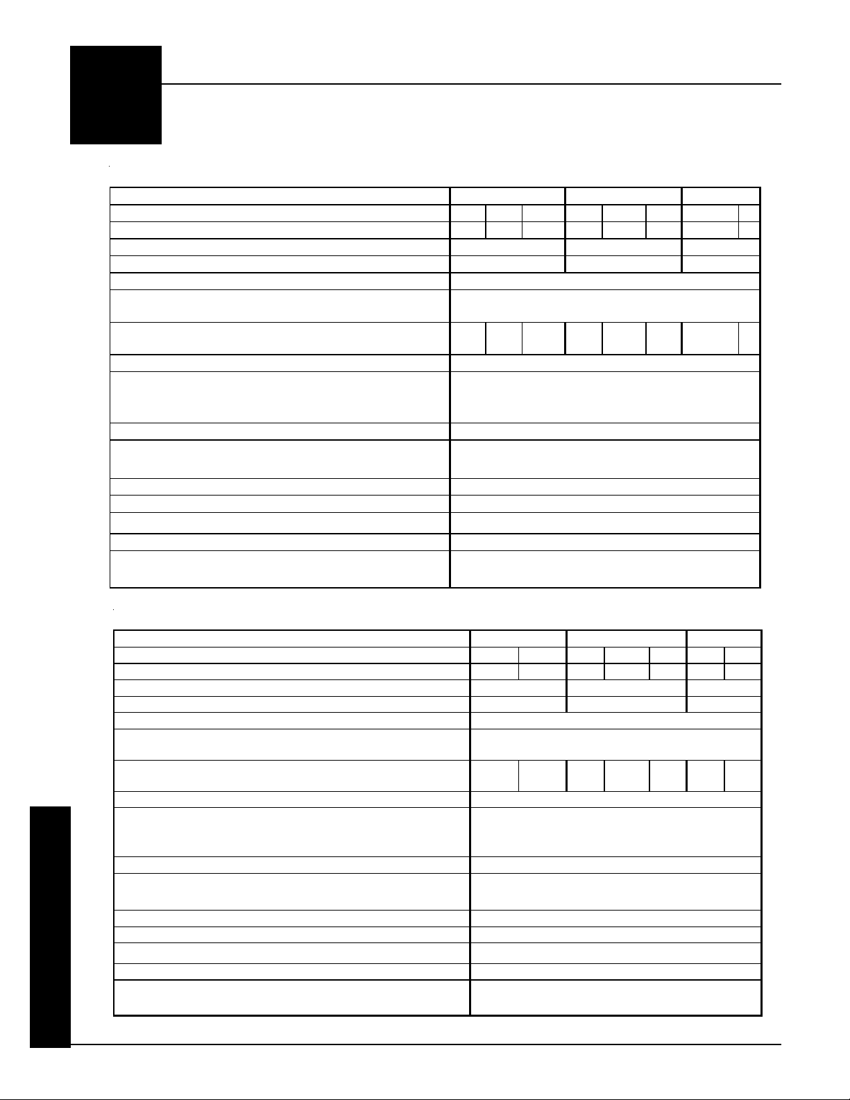
A
Control Circuit
See Note 2
240
277
347
208/240
1 GP M per 10,000 BT U of required output a t
20oF tem pera ture rise (10 GP M m a ximum )
180
120V (N e tural C onductor R equire d)
614,160
3,046
1”
Appendix
SPECIFICATIONS
Voltage
C harg ing Input (kW )
Element Current Draw (Amps)
Phase
Number of Wires - See Note 1
Control Circuit Voltage (VAC) - See Note 2
M inimum Circuit Ampacity (AM PS) for 240V
Single Fe ed Minimum C ircuit A mpacity (Amps) -
Pump Voltage - See Note 2
Sto rag e Cap acity - Se e N o te 3
kWh
BTU
A pproximate Ins talle d W e ight (lbs)
M ax Coil Dimensions (W x D x H ) - See Note 4
Pipe Size (Inle t/Outle t)
Prim ary Lo o p R e quirem ents
O utput Wate r Te m p - Se le ction R ang e
M aximum Working Pre s sure
Flow Rate (Primary Loop)
*The c ontrol circuit for 208 a nd 240 volt syste m s m ust be 3-w ire.
M odel 7120
240 277 347
14 19.2 24.8 19.2 20.48 24.8 19.2 26
59 80 104 24 25 30 19 25
Single Three Three
2* 4
208/240
10
83 110 140 34 36 43 28 36
120V (N e tural Conductor R equired)
120
409,440
2,218
½ H P : 21.2” x 21.2” x 24 ¼ ”
1 H P : 26.4” x 21.2” x 24 ½ ”
1”
M inimum of 10’ of 1” pipe
60 PSI / O ptiona l 20 P S I
1 GP M pe r 10,000 BTU of require d output at
o
20
F temperature rise (10 GPM maximum)
o
50
F to 185oF
4
Voltage
C harging Input (kW )
Element Current Draw (Amps)
Phase
N u m ber o f W ire s - S e e N o te 1
Control Circuit Voltage (VAC) - See Note 2
M inimum Circuit Ampacity (AM PS) for 240V
Control Circuit
Single Fee d M inim um Circuit Am pacity (Am ps ) See Note 2
Pump Voltage - See Note 2
Sto rag e C apac ity - Se e N o te 3
A pproximate Installe d Weig ht (lbs)
M ax Coil Dimensions (W x D x H) - See Note 4
Pipe Size (Inlet/Outlet)
Prim ary Loo p R e quire ments
Appendix
O utput Wate r T e m p - Sele ction R ange
M aximum Working Pressure
Flow Rate (Primary Loop)
M odel 7130
28.8 37.2 28.8 30.72 37.2 28.8 37.2
120 155 35 37 45 28 36
Single Thre e T hree
2* 4 4
10
160 204 49 52 61 39 49
kWh
BTU
½ H P : 21.2” x 21.2” x 24 ¼ ”
1 H P : 26.4” x 21.2” x 24 ½ ”
M inimum of 10’ of 1” pipe
50oF to 185oF
60 P SI / O ptional 20 PS I
*The c ontrol c ircuit for 208 and 240 volt system s mus t be 3-w ire.
Appendix n A.01 Comfort Plus Commercial Hydronic
Page 29
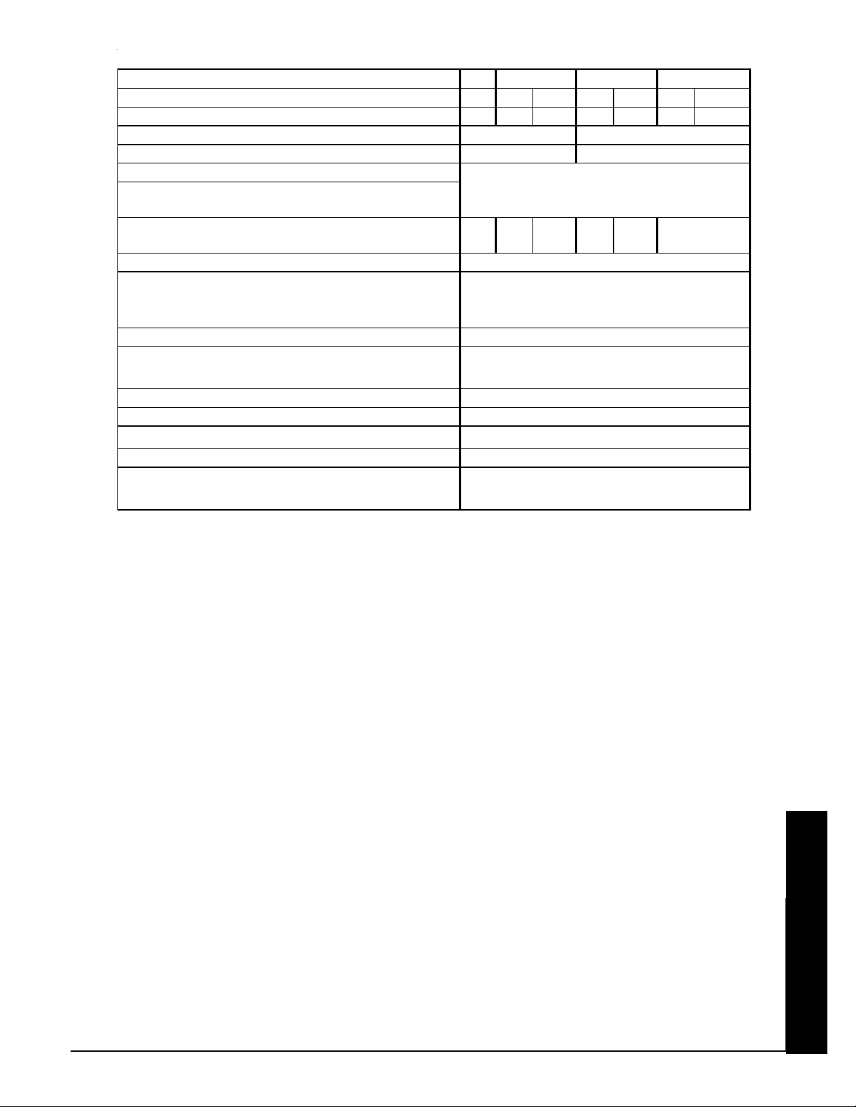
Vo ltage
Charging Input (kW)
Element Current Draw (Amps)
Phase
Number of Wire s
Control Circuit Voltage (VAC) - See Note 2
M inimum Circuit Ampacity (AMPS) for 240V
Control Circuit
Single F eed Minimum C ircuit Am pacity (A mps) See Note 2
Pump Voltage - See Note 2
Storag e Capacity - See N o te 3
kWh
BTU
Appro x imate I nstalle d Weight (lbs )
M ax Coil Dimensions (W x D x H) - See Note 4
Pipe Size (Inlet/Outlet)
Primary Lo o p Requirem ents
O utput Water Temp - Selec tio n R ang e
M aximum Working Pre s sure
Flow Rate (Primary Loop)
*The c o ntrol circuit for 208 a nd 240 volt systems m us t be 3-wire .
208
36 36 4 2. 7 5 38.4 46. 5 36 46.5
174 150 179 47 56 35 45
Single
198 233 60 63 75 48 60
120V ( N e tur a l Conductor R equired)
1 GP M per 10 ,000 BT U of required output at
o
20
F temperature rise (10 GPM maximum)
M odel 7140
240
2*
½ HP: 21.2” x 21.2” x 24 ¼ ”
1 H P: 26.4” x 21.2” x 24 ½ ”
Minimum of 10’ of 1” pipe
50
60 P SI / O ptional 20 PS I
277 347
Three
208/240
10
240
818,800
3,894
1”
o
F to 185oF
4
Note 1: 208V or 240V systems are factory configured to be field connected to multiple, single
phase, line voltage circuits. If single feed to element and blowers/system controls circuit
is desired, an optional single feed kit is available to order. Connection to 3-phase power
is acceptable and can improve phase balancing.
Note 2: Because 277V/480V and 347V/600V systems are configured for single feed, three phase
line voltage connections only, a step down transformer must be field installed.
Note 3: The size and heating ability of the system required for an installation is dependent on the
thermal load and the demand profile of the facility. The daily rate structure of the utility
can also affect size of furnace needed in an application. If the unit is not installed within
the heated area, heat lost statically must be taken into account when sizing a system.
Contact Steffes Corporation for assistance in selecting an appropriately sized system.
Note 4: The indoor coil or outdoor compressor of an air conditioner or heat pump are not in-
cluded with the furnace. The Steffes return air plenum (for use with the 6140) and the
Steffes air handler (for use with the 7140 to allow it to provide forced air heating), are
each configured to house an indoor coil and can be ordered from the factory as an optional
accessory. Dimensions listed are that of the inner coil area in the plenum. For larger
coils, field provisions to the factory built plenums are necessary or one will need to be
custom built by the installer. (In heat pump applications, the indoor coil MUST be placed
on the return air side.)
Appendix
Comfort Plus Commercial Hydronic Appendix n A.02
Appendix
Page 30
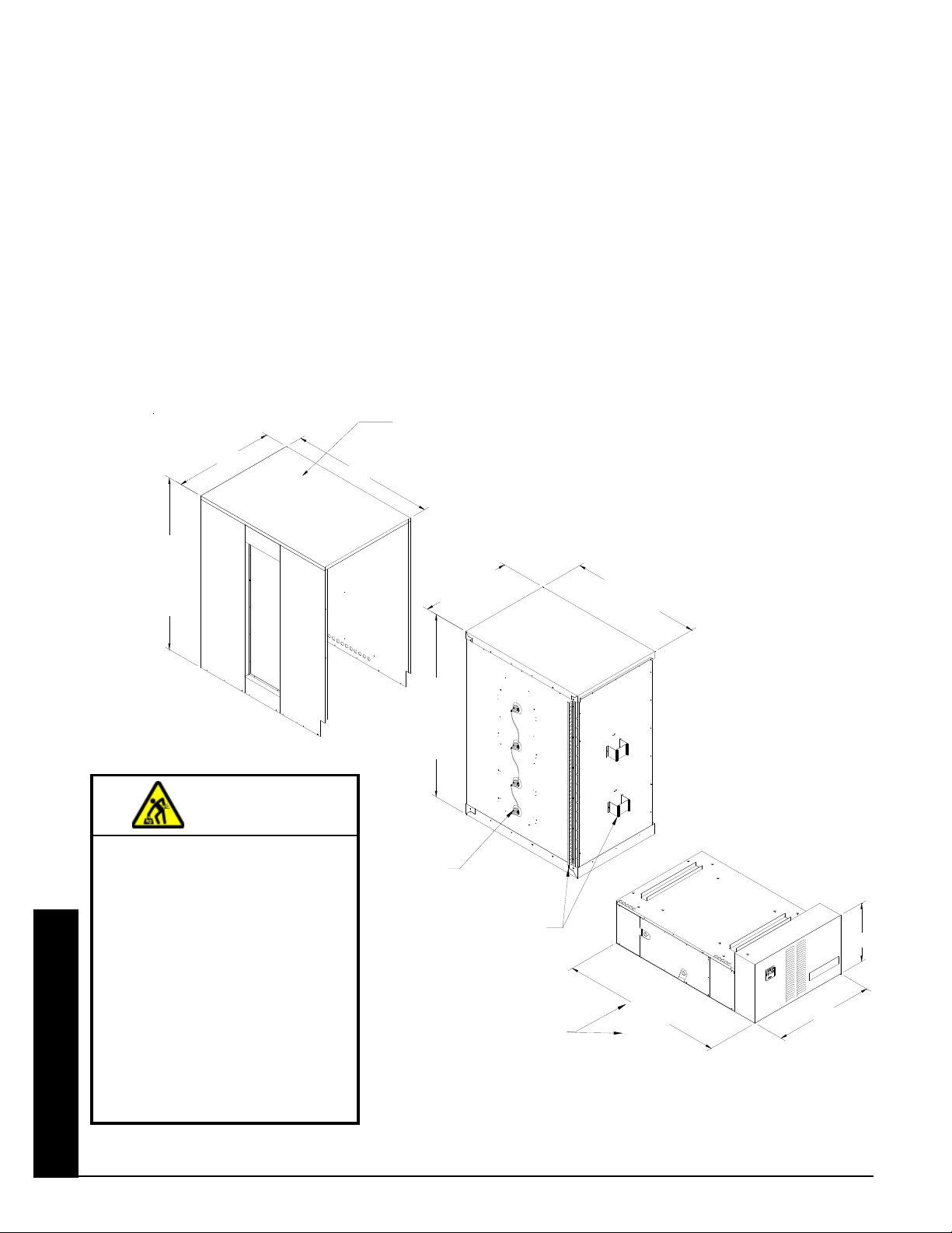
DISASSEMBLING THE COMFORT PLUS COMMERCIAL
HYDRONIC SYSTEM
Step 1 Remove the painted front panel of the brick storage cabinet by removing the sheet metal screws along
the top, bottom, and sides of the panel. Detach by pulling the bottom of the panel forward and down.
Step 2 Remove the limit zone cover by removing the screws holding it in place.
Step 3 Remove the screws around the perimeter of the limit zone and around the bottom of the left side, right
side, and back upper panels.
Step 4 Remove the one or two screws in the center of the upper right side panel.
Step 5 From the back of the system, lift and remove the painted panels. (See Figure A.)
Step 6 Locate the brick core temperature sensor(s) behind the front panel and disconnect them from their
shipping position. Carefully lay the sensor(s) aside to avoid damaging them.
Step 7 Carefully rock the brick core (Figure B) to one side and lift top portion up and off the base (Figure C.)
Step 8 Move the Comfort Plus Commercial Hydronic heating system into the desired location, reassemble, and
continue with the installation instructions in this manual.
Can be broken down into
individual panels.
29 3/16"
FIGURE A
42 5/16"
7140
56"
7130
45"
7120
34 1/2"
WARNING
HEAVY OBJECT WARNING:
Can cause muscle strain or
back injury.
w Use lifting aids to move
system into place.
w Do NOT place object,
hands, and/or body parts
under the system when
lifting.
w Use care to keep objects,
hands, and/or body parts
Appendix
clear of system when
lifting.
28 7/8"
Limits and Right
Side Saddle included
7140
54 3/4"
7130
43 3/4"
7120
32 3/4"
Do not remove
core limits.
Saddles and Z-brackets
can be removed if needed.
FIGURE B
Including
Breakers
38 1/8"
Plus front saddles
and back Z-Bracket
ALL 7100'S
48 1/4"
FIGURE C
17 1/4"
29 3/16"
Appendix n A.03 Comfort Plus Commercial Hydronic
Page 31
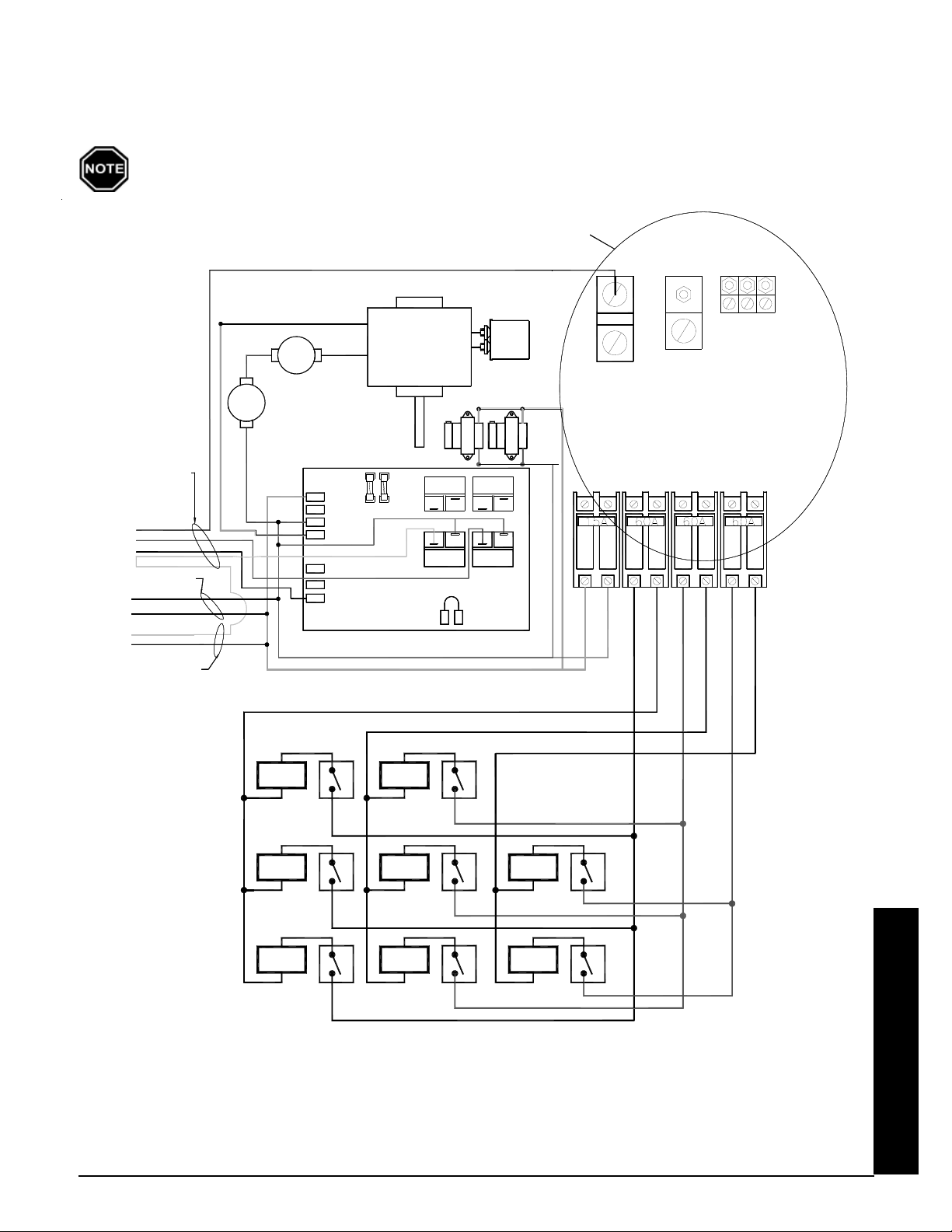
INTERNAL SYSTEM WIRING DIAGRAMS - LINE VOLTAGE
Line Voltage Wiring Diagram - Model 7120
240V OR 208V SYSTEMS ONLY
Use copper or aluminum conductors rated for 75
Red & White To
Primary Loop Pump
(Max 1.2 AMPS)
Black & White
To Air Handler Pump
(Max 1.2 AMPS)
SEE NOTE 2
WHITE
OR
WHITE/BLACK
RED
BLACK
ORANGE
To Optional Air Handler
BLUE/WHITE
BLUE/BLACK
ORANGE
BLACK
To Optional Static
Heat Recovery System
EXCHANGER
LIMITS
225 °
AUTO
RESET
N.C.
BLUE
BLACK/YELLOW
BLACK
250 °
WHITE
N.C.
MANUAL
RESET
BASE IO BOARD
5 Amp5 Amp
L1
L2 120
L2 240
BLOWER
RESISTOR
RESISTER
DAMPER
RED
BLACK/YELLOW
CORE BLOWER
HIGH
COM.
1/4 Amp1/4 Amp
COMCOM
NONO
NONO
COMCOM
SHRU
o
C or higher for field connection of this device.
SEE NOTE 1
4uf
Cap.
GROUND
LUGS
CONTROL CIRCUIT
TRANSFORMERS
240v / 24v
COMCOM
NONO
NONO
COMCOM
PRIMARY
LOOP PUMP
NEUTRAL LUG
BLOWERS/
CIRCUIT
CHARGE
BLACK
CIRCUIT #1
CONTROLS
CHARGE
RED
CIRCUIT #2
CHARGE
BLUE
CIRCUIT #3
Element
#7
Element
#4
Element
#1
Element
#8
Element
#5
Element
#2
Element
#6
Element
#3
NOTE 1: Line Voltage Field Wiring Connections. See Figure 8 for information on proper circuit phasing.
NOTE 2: For more information regarding pump (circulator) wiring, reference Figures 9, 15 and 16 in the
Installation section of this manual.
Comfort Plus Commercial Hydronic Appendix n A.04
Appendix
Page 32
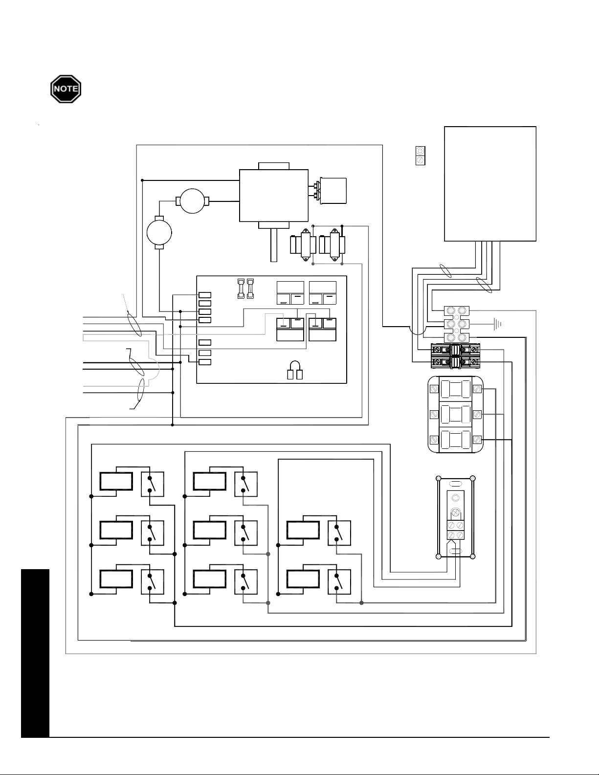
Line Voltage Wiring Diagram - Model 7120
277V AND 347V SYSTEMS ONLY
Use copper or aluminum conductors rated for 75
Red & White To
Primary Loop Pump
(Max 1.2 AMPS)
Black & White
To Air Handler Pump
(Max 1.2 AMPS)
SEE NOTE 2
WHITE
OR
WHITE/BLACK
RED
BLACK
ORANGE
To Optional Air Handler
BLUE/WHITE
BLUE/BLACK
EXCHANGER
LIMITS
225 °
AUTO
RESET
N.C.
BLUE
BLACK/YELLOW
250 °
N.C.
MANUAL
RESET
CORE BLOWER
BLACK
WHITE
HIGH
COM.
BASE IO BOARDBASE IO BOARD
5 Amp5 Amp
L1
L2 120
L2 240
BLOWER
RESISTOR
RESISTER
DAMPER
1/4 Amp1/4 Amp
COMCOM
NONO
FAN ONFAN ON
RELAYRELAY
TRANSFORMERS
COMCOM
NONO
NONO
COMCOM
HEAT CALLHEAT CALL
RELAYRELAY
o
C or higher for field connection of this device.
GROUND
LUG
FIELD
SUPPLIED
4uf
Cap.
240v / 24v
NONO
COMCOM
TRANSFORMER
PRIMARY
WHITE
Transformer
120/240 VAC
Secondary
TRANSFORMER
SECONDARY
ORANGE
BLACK
To Optional Static
Heat Recovery System
Element
#7
Element
#4
Element
#1
Element
#8
Element
#5
Element
RED
BLACK/YELLOW
NEUTRAL
BAR
Element
#6
Element
#3#2
Appendix
Appendix n A.05 Comfort Plus Commercial Hydronic
Page 33
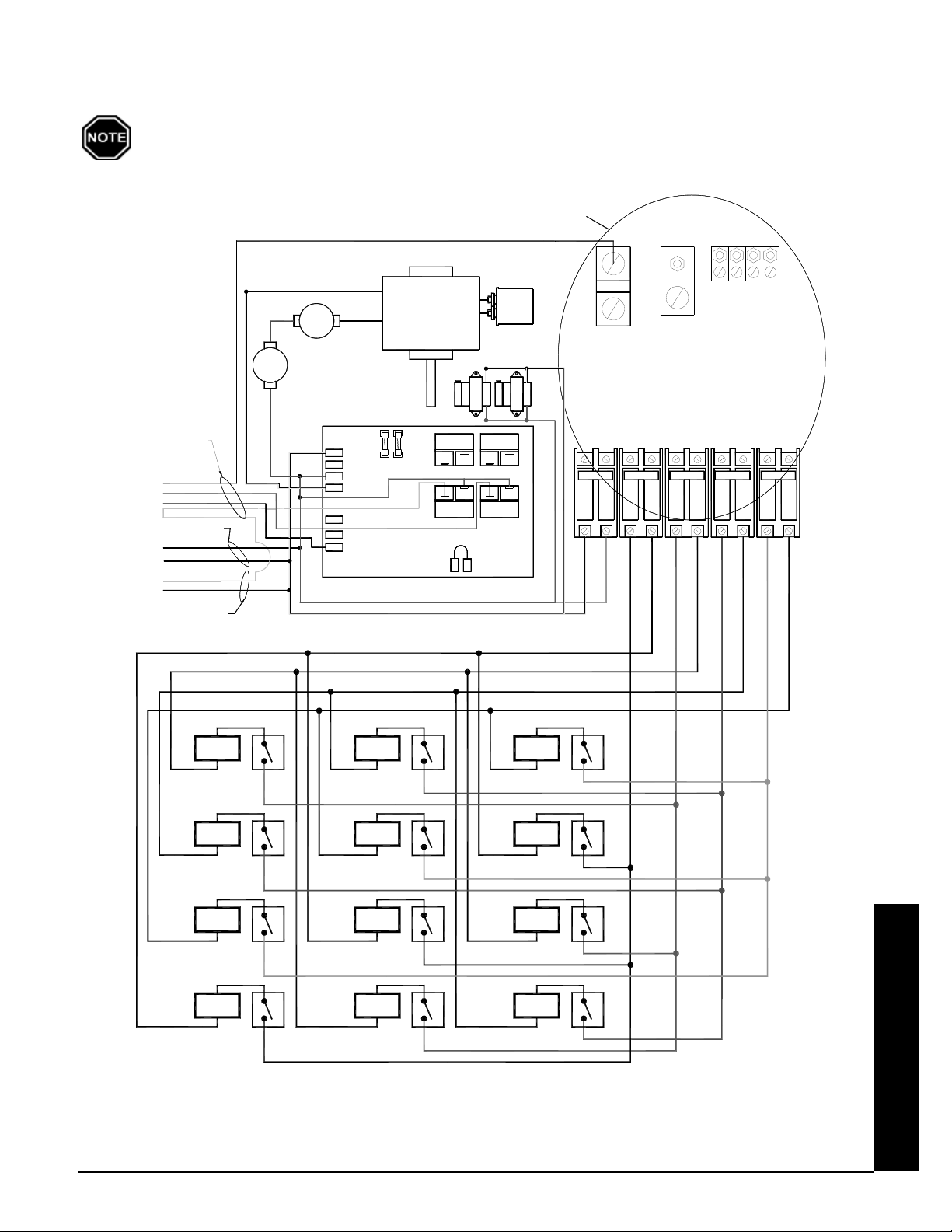
Line Voltage Wiring Diagram - Model 7130
208V AND 240V SYSTEMS ONLY
Use copper or aluminum conductors rated for 75
CORE BLOWER
BLACK
HIGH
WHITE
COM.
5 Amp5 Amp 1/4 Amp1/4 Amp
L1
L2 120
L2 240
BLOWER
RESISTOR
RESISTER
DAMPER
RED
BLACK/YELLOW
COMCOM
NONO
FAN ON
RELAY
NONO
COMCOM
Red & White To
Primary Loop Pump
(Max 1.2 AMPS)
Black & White
To Air Handler Pump
(Max 1.2 AMPS)
SEE NOTE 2
WHITE
OR
WHITE/BLACK
RED
BLACK
ORANGE
To Optional Air Handler
BLUE/WHITE
BLUE/BLACK
ORANGE
BLACK
To Optional Static
Heat Recovery System
EXCHANGER
LIMITS
225 °
N.C.
BLUE
BLACK/YELLOW
AUTO
RESET
250 °
N.C.
MANUAL
RESET
BASE IO BOARD
o
C or higher for field connection of this device.
SEE NOTE 1
4uf
Cap.
GROUND
LUGS
CONTROL CIRCUIT
TRANSFORMERS
240v / 24v
COMCOM
NONO
NONO
COMCOM
RELAY
NEUTRAL LUG
BLOWERS/
CIRCUIT
CONTROLS
CHARGE
15A
BLACK
CIRCUIT #1
CIRCUIT #2
CIRCUIT #3
CHARGE
CHARGE
60A
RED
BLUE
CHARGE
60A60A60A
BROWN
CIRCUIT #4
Element
#10
Element
#7
Element
#4
Element
#1
Element
#11
Element
#8
Element
#5
Element
#2
Element
#12
Element
#9
Element
#6
Element
#3
NOTE 1: Line Voltage Field Wiring Connections. See Figure 8 for information on proper circuit phasing.
NOTE 2: For more information regarding pump (circulator) wiring, reference Figures 9, 15 and 16 in the
Installation section of this manual.
Comfort Plus Commercial Hydronic Appendix n A.06
Appendix
Page 34
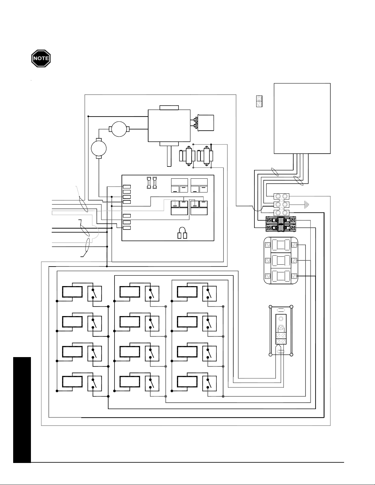
Line Voltage Wiring Diagram - Model 7130
277V AND 347V SYSTEMS ONLY
Use copper or aluminum conductors rated for 75oC or higher for field connection of this device.
CORE BLOWER
GROUND
LUG
FIELD
SUPPLIED
Red & White To
Primary Loop Pump
(Max 1.2 AMPS)
Black & White
To Air Handler Pump
(Max 1.2 AMPS)
SEE NOTE 2
WHITE
OR
WHITE/BLACK
RED
BLACK
ORANGE
To Optional Air Handler
BLUE/WHITE
BLUE/BLACK
ORANGE
BLACK
To Optional Static
Heat Recovery System
Element
#10
EXCHANGER
LIMITS
225 °
AUTO
RESET
N.C.
BLUE
BLACK/YELLOW
250 °
N.C.
MANUAL
RESET
BLACK
WHITE
BASE IO BOARDBASE IO BOARD
5 Amp5 Amp
L1
L2 120
L2 240
BLOWER
RESISTOR
RESISTER
DAMPER
RED
BLACK/YELLOW
Element
#11
HIGH
COM.
1/4 Amp1/4 Amp
COMCOM
NONO
FAN ONFAN ON
RELAYRELAY
Element
TRANSFORMERS
COMCOM
NONO
NONO
COMCOM
HEAT CALLHEAT CALL
RELAYRELAY
#12
4uf
Cap.
240v / 24v
NONO
COMCOM
TRANSFORMER
PRIMARY
WHITE
Transformer
120/240 VAC
Secondary
NEUTRAL
BAR
TRANSFORMER
SECONDARY
Element
#7
Element
#4
Element
#1
Element
#8
Element
#5
Element
Element
#9
Element
#6
Element
#3#2
Appendix
Appendix n A.07 Comfort Plus Commercial Hydronic
Page 35
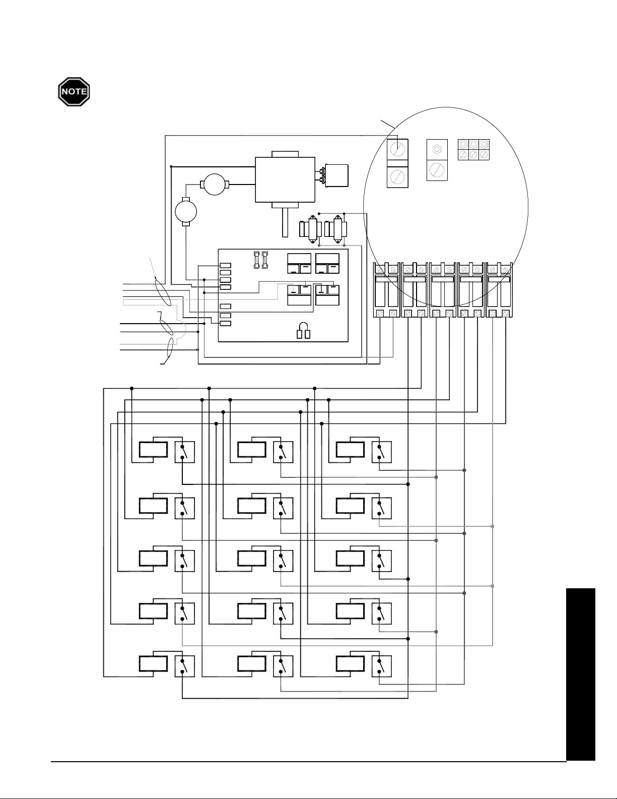
Line Voltage Wiring Diagram - Model 7140
240V OR 208V SYSTEMS ONLY
Use copper or aluminum conductors rated for 75
CORE BLOWER
BLACK
WHITE
5 Amp5 Amp
L1
L2 120
L2 240
BLOWER
RESISTOR
RESISTER
DAMPER
RED
BLACK/YELLOW
HIGH
COM.
1/4 Amp1/4 Amp
COMCOM
NONO
FAN ON
COMCOM
RELAY
TRANSFORMERS
COMCOM
NONO
NONO
RELAY
Red & White To
Primary Loop Pump
(Max 1.2 AMPS)
Black & White
To Air Handler Pump
(Max 1.2 AMPS)
SEE NOTE 2
WHITE
OR
WHITE/BLACK
RED
BLACK
ORANGE
To Optional Air Handler
BLUE/WHITE
BLUE/BLACK
ORANGE
BLACK
To Optional Static
Heat Recovery System
EXCHANGER
LIMITS
225 °
N.C.
BLUE
BLACK/YELLOW
AUTO
RESET
250 °
N.C.
MANUAL
RESET
BASE IO BOARD
o
C or higher for field connection of this device.
SEE NOTE 1
4uf
Cap.
GROUND
LUGS
CONTROL CIRCUIT
240v / 24v
NONO
COMCOM
NEUTRAL LUG
BLOWERS/
CIRCUIT
CONTROLS
CHARGE
60A
15A
BLACK
CIRCUIT #1
CIRCUIT #2
CHARGE
60A
RED
CIRCUIT #3
CHARGE
60A
BLUE
CIRCUIT #4
CHARGE
60A
BROWN
Element
#13
Element
#10
Element
#7
#4
Element
#1
Element
#14
Element
#11
Element
#8
ElementElement
#5
Element
#2
Element
#15
Element
#12
Element
#9
Element
#6
Element
#3
NOTE 1: Line Voltage Field Wiring Connections. See Figure 8 for information on proper circuit phasing.
NOTE 2: For more information regarding pump (circulator) wiring, reference Figures 9, 15 and 16 in the
Installation section of this manual.
Appendix
Comfort Plus Commercial Hydronic Appendix n A.08
Page 36
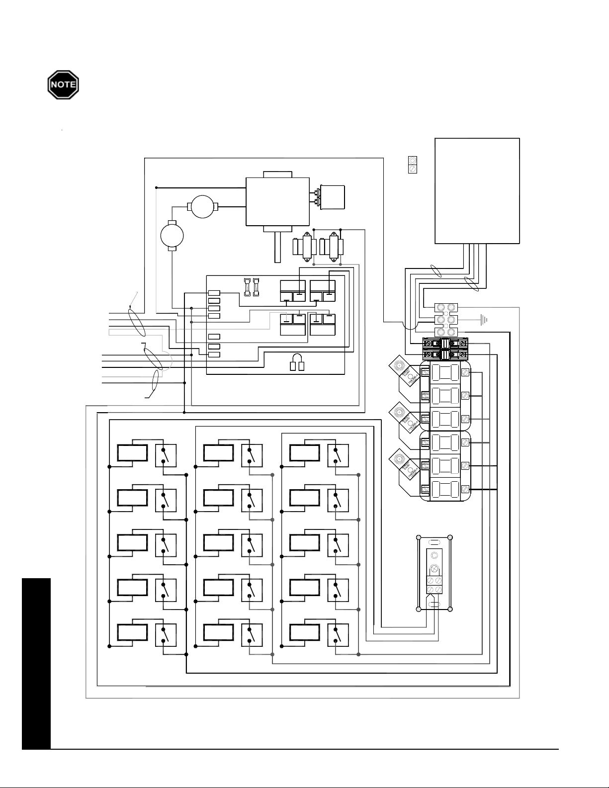
Line Voltage Wiring Diagram - Model 7140
277V AND 347V SYSTEMS ONLY
Use copper or aluminum conductors rated for 75
CORE BLOWER
BLACK
HIGH
WHITE
COM.
BASE IO BOARDBASE IO BOARD
1/4 Amp1/4 Amp
5 Amp5 Amp
L1
L2 120
L2 240
BLOWER
RESISTOR
RESISTER
DAMPER
RED
BLACK/YELLOW
LOW
SPEED
COMCOM
NONO
FAN ON
FAN ON
RELAY
RELAY
Red & White To
Primary Loop Pump
(Max 1.2 AMPS)
Black & White
To Air Handler Pump
(Max 1.2 AMPS)
WHITE
RED
BLACK
ORANGE
To Optional Air Handler
BLUE/WHITE
BLUE/BLACK
BLUE/RED
ORANGE
BLACK
To Optional Static
Heat Recovery System
EXCHANGER
LIMITS
225 °
N.C.
BLUE
BLACK/YELLOW
AUTO
RESET
250 °
N.C.
MANUAL
RESET
o
C or higher for field connection of this device.
GROUND
LUG
FIELD
SUPPLIED
Transformer
120/240 VAC
Secondary
TRANSFORMER
SECONDARY
TRANSFORMERS
HIGH
SPEED
COMCOM
NONO
NONO
COMCOM
HEAT CALLHEAT CALL
RELAYRELAY
4uf
Cap.
240v / 24v
NONO
COMCOM
TRANSFORMER
PRIMARY
WHITE
Appendix
Element
#13
Element
#10
Element
#7
Element
#4
Element
#1
Element
#14
Element
#11
Element
#8
Element
#5
Element
#2
Element
#15
Element
#12
Element
#9
Element
#6
Element
#3
NEUTRAL
BAR
Appendix n A.09 Comfort Plus Commercial Hydronic
Page 37
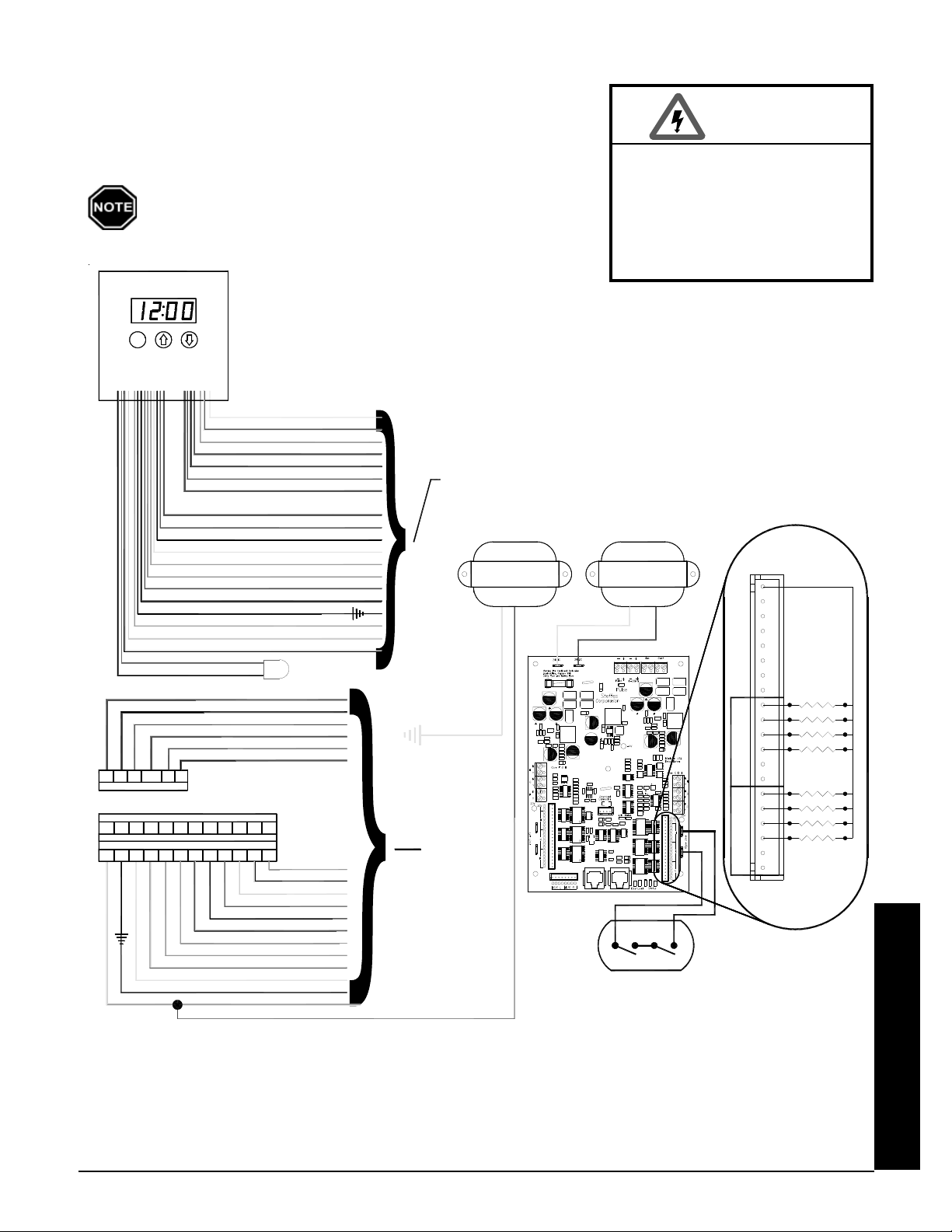
INTERNAL SYSTEM WIRING DIAGRAM - LOW VOLTAGE
BLUE
The outdoor temperature sensor, room thermostat, and peak control device
are connected via low voltage wiring.
WARNING
System Low Voltage Wiring Diagram - Model 7120
The "R" and "C" positions in the low voltage terminal
strip may be used as a source of 24 VAC for powering
external low voltage devices (60 VA maximum).
A
M
P
M
M
CONTROL BOARD
BLUE/RED
BLUE/YELLOW
BLUE/WHITE
GRAY/WHITE
PURPLE/WHITE
COM
AP
RP
PNONC
Peak Control Connections
Terminals for Connection as a Stand Alone Furnace
RWCY2YG
Terminals for Connection with Heat Pump
RY2YCO2OG
YELLOW
YELLOW/BLUE
ORANGE
ORANGE/BLUE
BLUE/WHITE
BLUE
BLUE/RED
RED
WHITE
YELLOW
ORANGE
GREEN
BLACK
BROWN
GRAY
PURPLE
OSW2 DSSC
E OSW DSSC
YELLOW AND ORANGE
WATER SENSOR
BLUE/RED
BLUE/WHITE
BLUE/YELLOW
BLUE/RED
BLUE/WHITE
BROWN
GRAY/WHITE
WHITE
ORANGE/BLUE
ORANGE
GREEN
YELLOW/BLUE
YELLOW
BLACK
"R"
"Y2"
"R"
"O2"
"NO"
"NC"
"COM"
"RP"
"E"
"W"
"Y"
"O"
"G"
"AP"
"P"
"C"
"DS"
"OS"
"SC"
DISCHARGE
BLUE
GRAY
RED
8
15
14
7
6
5
17
19
18
9
10
4
12
13
2
11
16
1 & 3
1
2
3
4
5
6
7
8
9
10
11
12
13
14
15
16
17
18
19
CONTROL
NOTE
TO LOW VOLTAGE
TERMINAL BLOCKS
YELLOW
TO
BOARD
HAZARDOUS VOLTAGE: Risk
of electric shock. Can cause
injury or death. All low voltage
wiring must be segregated
from line voltage circuits in
the system.
The "R" and "C" positions in the low voltage terminal
strip may be used as a source of 24 VAC for powering
external low voltage devices (60 VA maximum)
TX1
75 VA
TRANSFORMER
GROUNDED
YELLOW
TX2
75 VA
TRANSFORMER
UN-GROUNDED
BLUE
CORE LIMITS
20V DC
RELAY 8
RELAY 7
RELAY 6
RELAY 5
CORE DCORE C
RELAY 4
RELAY 3
RELAY 2
RELAY 1
Appendix
Comfort Plus Commercial Hydronic Appendix n A.10
Page 38
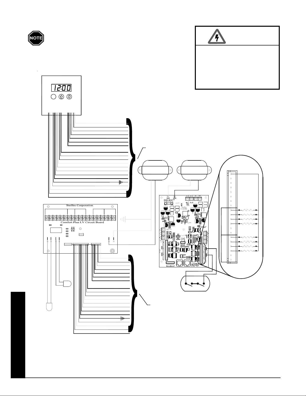
System Low Voltage Wiring Diagram - Model 7120 with Variable Speed
The "R" and "C" positions in the low voltage terminal
strip may be used as a source of 24 VAC for powering
external low voltage devices (60 VA maximum).
A
M
P
M
M
CONTROL BOARD
YELLOW
YELLOW
ORANGE
ORANGE
WHITE/BLACK
WHITE
WHITE/RED
RED/BLACK
RED
WHITE
YELLOW
ORANGE
GREEN
YELLOW/BLACK
WHITE/BLACK
BLACK
BROWN
GRAY
BLUE
BLUE/BLACK
"R"
"Y2"
"R"
"O2"
"NO"
"NC"
"COM"
"RP"
"E"
"W"
"Y"
"O"
"G"
"AP"
"P"
"C"
"DS"
"OS"
"SC"
"RS"
1
2
3
4
5
6
7
8
9
10
11
12
13
14
15
16
17
18
19
20
TO LOW VOLTAGE BOARD
TX1
75 VA
TRANSFORMER
GROUNDED
YELLOW
HAZARDOUS VOLTAGE: Risk
of electric shock. Can cause
injury or death. All low voltage
wiring must be segregated
from line voltage circuits in
the system.
TX2
75 VA
TRANSFORMER
UN-GROUNDED
BLUE
WARNING
20V DC
W/
AUX
P11
(OPTIONAL
HANDLER)
DISCHARGE
SENSOR
Appendix
AIR
AIR
Thermostat
Y1
J5
Y1 Y2
RLY1
Air
OG
Y2
H/E
Blower
J6
W/E
Speed
J1
A
J2
B
J3
C
Water
J4
D
P3P2P1
P4
Blower
P5
DISCHARGE
WATER
SENSOR
Heat Aux.
24
Pump
VAC
Y1
O
2
CR
2Y22
D1
D2
To Control Board
P6
Peak
Inputs
P
RP
Outdoor
Outdoor
P7
YELLOW/BLACK
ORANGE/BLACK
RED/BLACK
RED
WHITE
YELLOW
ORANGE
GREEN
YELLOW/BLACK
WHITE/BLACK
BLACK
BROWN
GRAY
BLUE
BLUE/BLACK
Relay
NO
NCAP CO M
P8CP9
R
YELLOW
ORANGE
WHITE/BLACK
WHITE
WHITE/RED
C
R
YELLOW
BLUE
1
2
3
4
5
6
7
8
9
10
11
12
13
14
15
16
17
18
19
20
RELAY 8
RELAY 7
RELAY 6
RELAY 5
CORE DCORE C
RELAY 4
RELAY 3
RELAY 2
RELAY 1
CORE LIMITS
TO CONTROL BOARD
Appendix n A.11 Comfort Plus Commercial Hydronic
Page 39
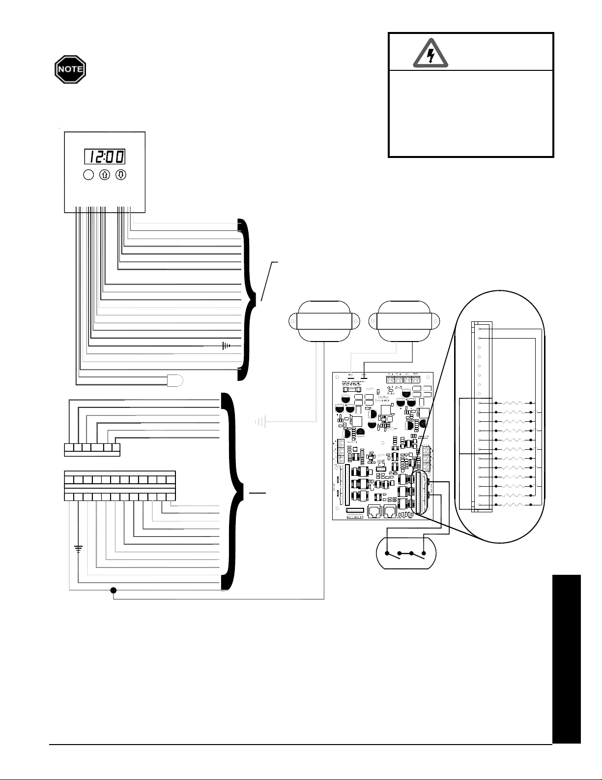
System Low Voltage Wiring Diagram - 7130
The "R" and "C" positions in the low voltage terminal
strip may be used as a source of 24 VAC for powering
external low voltage devices (60 VA maximum).
A
M
P
M
M
CONTROL BOARD
BLUE/RED
BLUE/YELLOW
BLUE/WHITE
GRAY/WHITE
PURPLE/WHITE
COM
RP
PNONC
AP
Peak Control Connections
Terminals for Connection as a Stand Alone Furnace
RWCY2YG
Terminals for Connection with Heat Pump
RY2YCO2OG
YELLOW
YELLOW/BLUE
ORANGE
ORANGE/BLUE
BLUE/WHITE
BLUE
BLUE/RED
RED
WHITE
YELLOW
ORANGE
GREEN
BLACK
BROWN
GRAY
PURPLE
BLUE/RED
BLUE/WHITE
BLUE/YELLOW
BLUE/RED
BLUE/WHITE
OSW2 DSSC
E OSW DSSC
YELLOW AND ORANGE
BROWN
GRAY/WHITE
WHITE
ORANGE/BLUE
ORANGE
GREEN
YELLOW/BLUE
YELLOW
BLACK
"R"
"Y2"
"R"
"O2"
"NO"
"NC"
"COM"
"RP"
"E"
"W"
"Y"
"O"
"G"
"AP"
"P"
"C"
"DS"
"OS"
"SC"
DISCHARGE
WATER SENSOR
8
15
14
7
6
BLUE
5
17
19
GRAY
18
9
RED
10
4
12
13
2
11
16
1 & 3
1
2
3
4
5
6
7
8
9
10
11
12
13
14
15
16
17
18
19
CONTROL
NOTE
TO LOW VOLTAGE
TERMINAL BLOCKS
YELLOW
TO
BOARD
BLUE
WARNING
HAZARDOUS VOLTAGE: Risk
of electric shock. Can cause
injury or death. All low voltage
wiring must be segregated
from line voltage circuits in
the system.
The "R" and "C" positions in the low voltage terminal
strip may be used as a source of 24 VAC for powering
external low voltage devices (60 VA maximum)
TX1
75 VA
TRANSFORMER
GROUNDED
YELLOW
TX2
75 VA
TRANSFORMER
UN-GROUNDED
BLUE
CORE LIMITS
CORE D
CORE C
20V DC
20V DC
RELAY 12
RELAY 11
RELAY 10
RELAY 9
RELAY 8
RELAY 7
RELAY 6
RELAY 5
RELAY 4
RELAY 3
RELAY 2
RELAY 1
Comfort Plus Commercial Hydronic Appendix n A.12
Appendix
Page 40
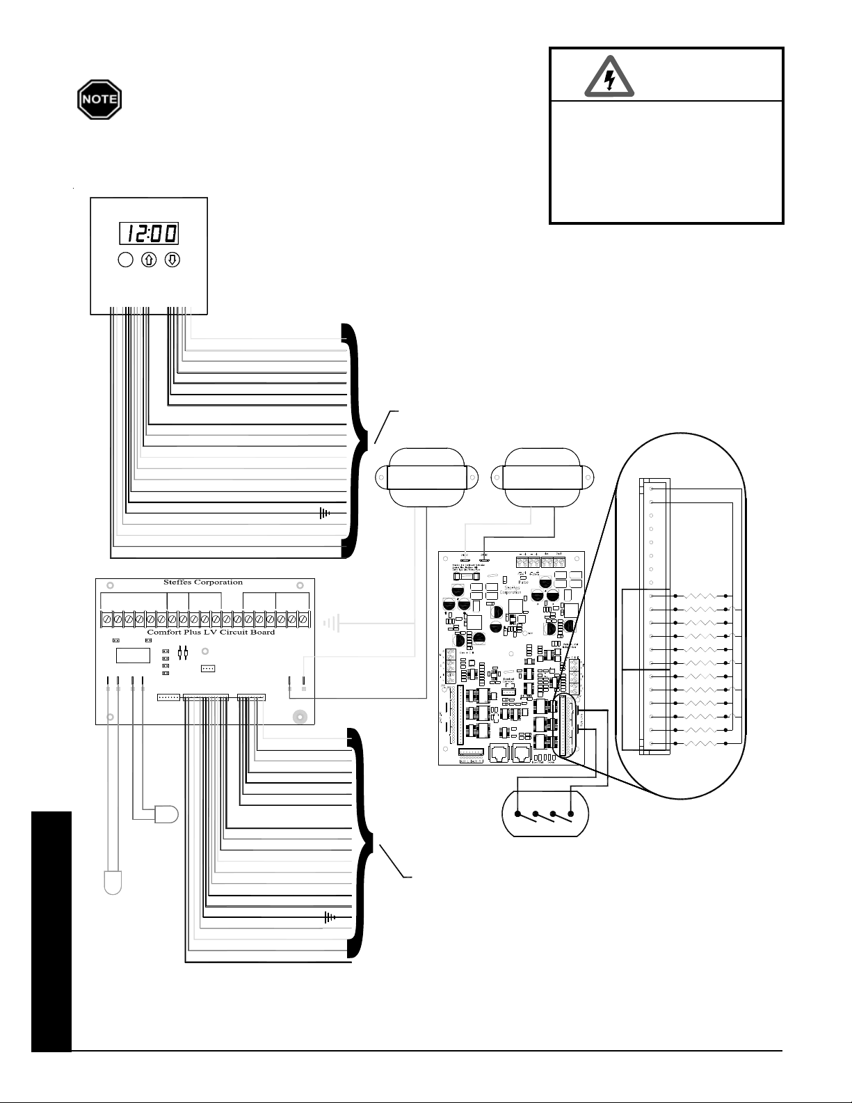
System Low Voltage Wiring Diagram - 7130 with Variable Speed
The "R" and "C" positions in the low voltage terminal
strip may be used as a source of 24 VAC for powering
external low voltage devices (60 VA maximum).
A
M
P
M
M
CONTROL BOARD
YELLOW
YELLOW
ORANGE
ORANGE
WHITE/BLACK
WHITE
WHITE/RED
RED/BLACK
RED
WHITE
YELLOW
ORANGE
GREEN
YELLOW/BLACK
WHITE/BLACK
BLACK
BROWN
GRAY
BLUE
BLUE/BLACK
"R"
"Y2"
"R"
"O2"
"NO"
"NC"
"COM"
"RP"
"E"
"W"
"Y"
"O"
"G"
"AP"
"P"
"C"
"DS"
"OS"
"SC"
"RS"
1
2
3
4
5
6
7
8
9
10
11
12
13
14
15
16
17
18
19
20
TO LOW VOLTAGE BOARD
TX1
75 VA
TRANSFORMER
GROUNDED
TRANSFORMER
UN-GROUNDED
YELLOW
BLUE
WARNING
HAZARDOUS VOLTAGE: Risk
of electric shock. Can cause
injury or death. All low voltage
wiring must be segregated
from line voltage circuits in
the system.
TX2
75 VA
20V DC
20V DC
Thermostat
W/
AUX
Y1
Y2
P11
J5
Y1 Y2
RLY1
Water
Air
DISCHARGE
(OPTIONAL
AIR
HANDLER)
DISCHARGE
AIR
SENSOR
Appendix
OG
J6
W/E
P3P2P1
P4
WATER
SENSOR
H/E
Blower
Speed
A
B
C
D
Blower
P5
Heat Aux.
24
Pump
VAC
Y1
2
CR
J1
D1
J2
D2
J3
J4
P6
O
2Y22
Outdoor
To Control Board
P7
Peak
Inputs
Relay
P
RP
Outdoor
R
YELLOW
YELLOW/BLACK
ORANGE
ORANGE/BLACK
WHITE/BLACK
WHITE
WHITE/RED
RED/BLACK
RED
WHITE
YELLOW
ORANGE
GREEN
YELLOW/BLACK
WHITE/BLACK
BLACK
BROWN
GRAY
BLUE
BLUE/BLACK
NCAP COM
P8CP9
RELAY 12
NO
C
R
YELLOW
BLUE
1
2
3
4
5
6
7
8
9
10
11
12
13
14
CORE D
CORE C
CORE LIMITS
TO CONTROL BOARD
RELAY 11
RELAY 10
RELAY 9
RELAY 8
RELAY 7
RELAY 6
RELAY 5
RELAY 4
RELAY 3
RELAY 2
RELAY 1
15
16
17
18
19
20
Appendix n A.13 Comfort Plus Commercial Hydronic
Page 41
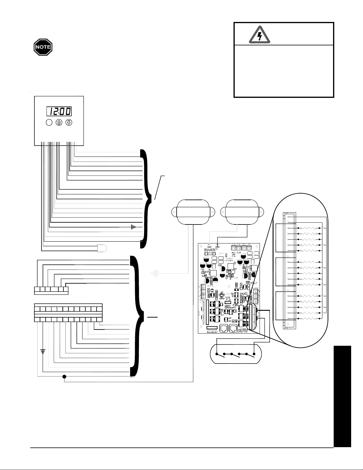
System Low Voltage Wiring Diagram - 7140
The "R" and "C" positions in the low voltage terminal
strip may be used as a source of 24 VAC for powering
external low voltage devices (60 VA maximum).
A
M
P
M
M
CONTROL BOARD
BLUE/RED
BLUE/YELLOW
BLUE/WHITE
GRAY/WHITE
PURPLE/WHITE
COM
RP
PNONC
AP
Peak Control Connections
Terminals for Connection as a Stand Alone Furnace
RWCY2YG
Terminals for Connection with Heat Pump
RY2YCO2OG
YELLOW
YELLOW/BLUE
ORANGE
ORANGE/BLUE
BLUE/WHITE
BLUE
BLUE/RED
RED
WHITE
YELLOW
ORANGE
GREEN
BLACK
BROWN
GRAY
PURPLE
WATER SENSOR
BLUE/RED
BLUE/WHITE
BLUE/YELLOW
BLUE/RED
BLUE/WHITE
OSW2 DSSC
E OSW DSSC
YELLOW AND ORANGE
BROWN
GRAY/WHITE
WHITE
ORANGE/BLUE
ORANGE
GREEN
YELLOW/BLUE
YELLOW
BLACK
"R"
"Y2"
"R"
"O2"
"NO"
"NC"
"COM"
"RP"
"E"
"W"
"Y"
"O"
"G"
"AP"
"P"
"C"
"DS"
"OS"
"SC"
DISCHARGE
BLUE
GRAY
RED
8
15
14
7
6
5
17
19
18
9
10
4
12
13
2
11
16
1 & 3
1
2
3
4
5
6
7
8
9
10
11
12
13
14
15
16
17
18
19
TO LOW VOLTAGE
TERMINAL BLOCKS
YELLOW
TO
CONTROL
BOARD
HAZARDOUS VOLTAGE: Risk
of electric shock. Can cause
injury or death. All low voltage
wiring must be segregated
from line voltage circuits in
the system.
The "R" and "C" positions in the low voltage terminal
NOTE
strip may be used as a source of 24 VAC for powering
external low voltage devices (60 VA maximum)
TX1
75 VA
TRANSFORMER
GROUNDED
YELLOW
TX2
75 VA
TRANSFORMER
UN-GROUNDED
BLUE
CORE LIMITS
BLUE
WARNING
20V DC
20V DC
RELAY 15
RELAY 14
RELAY 13
CORE ECORE D
CORE C
RELAY 12
RELAY 11
RELAY 10
RELAY 9
RELAY 8
RELAY 7
RELAY 6
RELAY 5
RELAY 4
RELAY 3
RELAY 2
RELAY 1
Comfort Plus Commercial Hydronic Appendix n A.14
Appendix
Page 42
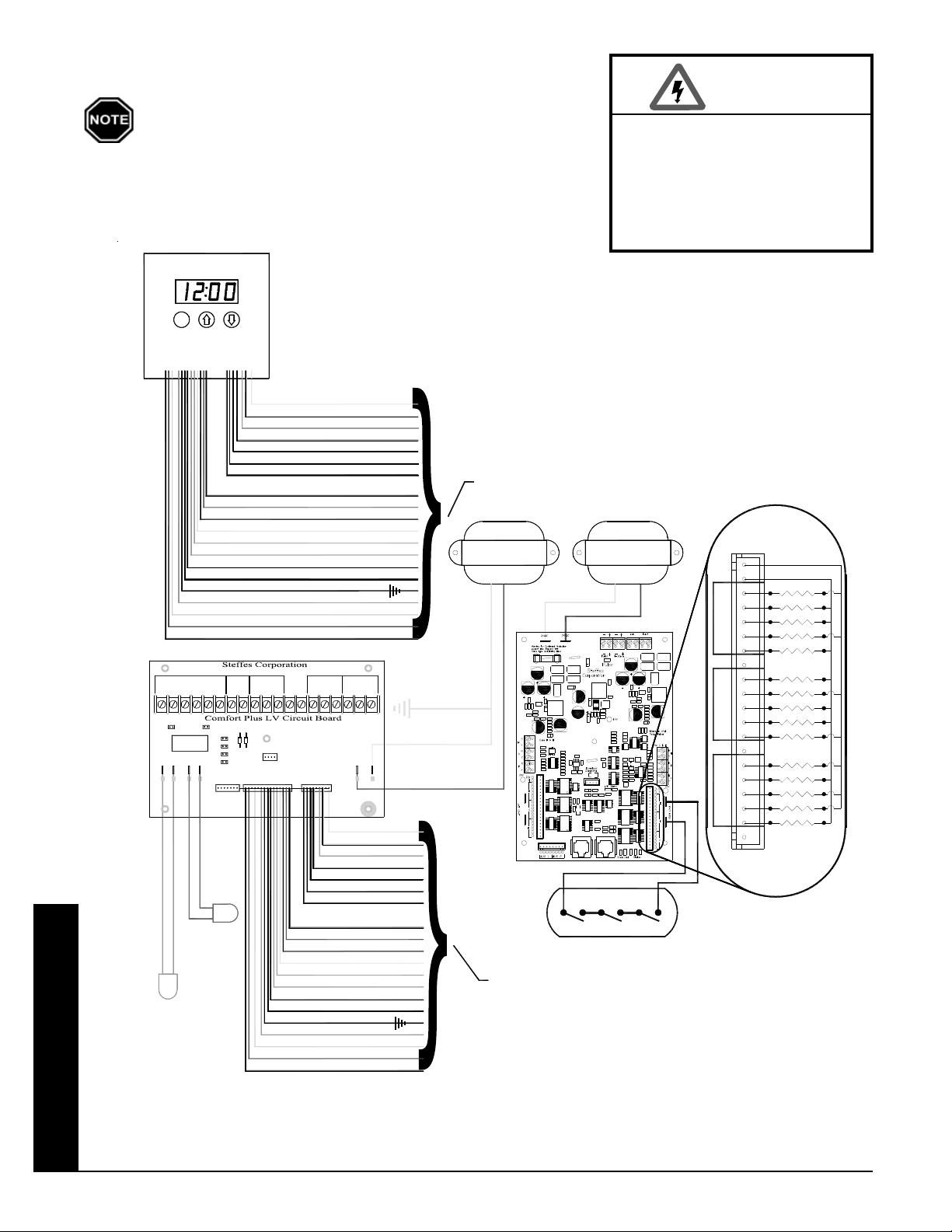
System Low Voltage Wiring Diagram - 7140 with Variable Speed
The "R" and "C" positions in the low voltage terminal
strip may be used as a source of 24 VAC for powering
external low voltage devices (60 VA maximum).
A
M
P
M
M
CONTROL BOARD
YELLOW
YELLOW
ORANGE
ORANGE
WHITE/BLACK
WHITE
WHITE/RED
RED/BLACK
RED
WHITE
YELLOW
ORANGE
GREEN
YELLOW/BLACK
WHITE/BLACK
BLACK
BROWN
GRAY
BLUE
BLUE/BLACK
"R"
"Y2"
"R"
"O2"
"NO"
"NC"
"COM"
"RP"
"E"
"W"
"Y"
"O"
"G"
"AP"
"P"
"C"
"DS"
"OS"
"SC"
"RS"
1
2
3
4
5
6
7
8
9
10
11
12
13
14
15
16
17
18
19
20
TRANSFORMER
The "R" and "C" positions in the low voltage terminal
NOTE
strip may be used as a source of 24 VAC for powering
external low voltage devices (60 VA maximum)
TO LOW VOLTAGE BOARD
TX1
75 VA
GROUNDED
TRANSFORMER
UN-GROUNDED
YELLOW
BLUE
WARNING
HAZARDOUS VOLTAGE: Risk
of electric shock. Can cause
injury or death. All low voltage
wiring must be segregated
from line voltage circuits in
the system.
TX2
75 VA
CORE ECORE D
20V DC
20V DC
RELAY 15
RELAY 14
RELAY 13
RELAY 12
RELAY 11
(OPTIONAL
HANDLER)
DISCHARGE
Appendix
W/
AUX
Y1
P11
J5
Y1 Y2
RLY1
Air
AIR
AIR
SENSOR
Thermostat
OG
Y2
H/E
Blower
J6
W/E
Speed
A
B
C
Water
D
P3P2P1
P4
Blower
P5
DISCHARGE
WATER
SENSOR
Heat
24
Pump
VAC
Y1
O
2
CR
2Y22
Outdoor
Outdoor
J1
D1
J2
D2
J3
J4
To Control Board
P6
P7
Aux.
Peak
Inputs
Relay
P
RP
NCAP COM
P8CP9
R
YELLOW
YELLOW/BLACK
ORANGE
ORANGE/BLACK
WHITE/BLACK
WHITE
WHITE/RED
RED/BLACK
RED
WHITE
YELLOW
ORANGE
GREEN
YELLOW/BLACK
WHITE/BLACK
BLACK
BROWN
GRAY
BLUE
BLUE/BLACK
NO
YELLOW
C
R
BLUE
1
2
3
4
5
6
7
8
9
10
11
12
13
14
15
16
17
18
19
20
TO CONTROL BOARD
CORE LIMITS
CORE C
RELAY 10
RELAY 9
RELAY 8
RELAY 7
RELAY 6
RELAY 5
RELAY 4
RELAY 3
RELAY 2
RELAY 1
Appendix n A.15 Comfort Plus Commercial Hydronic
Page 43
HELP MENU
The Comfort Plus Commercial Hydronic system contains a "HELP" menu which may be accessed through the
control panel. To access the "HELP" menu, press and release the M button until the faceplate displays
HELP. Scroll through this menu by pressing either the up or the down arrow button.
Display
Reading Description
Fxxx Firmware Version Number - Indicates the version of software installed.
O xx Outdoor Temperature - Indicates current outdoor temperature as recognized by the system.
tL:xx Target Level - Indicates the percentage of brick core charge level the system is targeting. During
peak periods the value displays as "tL_".
CL:xx Charge Level - Indicates the percentage of heat storage currently in the brick core.
HE x Heating Elements Active - Indicates the total number of heating elements currently energized.
PC x Power Line Carrier Channel - Indicates the channel on which the system is set to receive PLC
communication signal.
P x Power Line Carrier Net Hit Rate Percentage - Indicates the percentage of "GOOD" communica-
tion packets received by the system from the PLC transmitter system.
PS x Indicates which Specialty Timer the system is currently using. The value displayed will be zero if
the Specialty Timer is not being utilized.
CC_x Charge Mode Operation - Indicates the charge control method being utilized during off-peak
periods.
CA_x A-Peak Mode Operation - Indicates the charge control method being utilized during anticipated
peak periods.
C1_x Specialty Timer #1 Charge Mode - Specialty Applications Only
C2_x Specialty Timer #2 Charge Mode - Specialty Applications Only
HUxx Heat Usage - Indicates the amount of input being dissipated by the system.
A_xx Target Discharge Air Temperature - Indicates the discharge air temperature that the system is
targeting.
cxxx Compressor Output Relay Delay Timer - Indicates time remaining before heat pump compressor
is energized. "c ON" indicates the heat pump is energized.
ERROR CODES
The Comfort Plus Commercial Hydronic system has an on-board diagnostic system to monitor various operating
conditions. If operating conditions move outside the normal operating range, an error code is displayed on the
faceplate. If there are multiple errors simultaneously, only the highest priority
error code appears. Once corrected, the next highest priority code will be
displayed. Error codes will be displayed on the faceplate as Er (i.e., Er05).
Error Code Description
03 Outlet water temperature is out of normal operating range.
This can indicate an open sensor, a short in the wiring, or a
circuit board which is out of calibration.
04 Discharge air temperature is out of normal operating range.
This can indicate an open sensor, a short in the wiring, or a
circuit board which is out of calibration.
05 Outdoor sensor (direct wired) temperature reading is out of
normal operating range. The sensor circuit may be open or
shorted, the processor control board may be out of calibration,
or there may be an incorrect value in L035.
Comfort Plus Commercial Hydronic Appendix n A.16
HAZARDOUS VOLTAGE:
Risk of electric shock.
Can cause injury or
death. System may be
connected to more than
one branch circuit.
Disconnect power to all
circuits before servicing. Equipment must be
serviced by a qualified
technician.
WARNING
Appendix
Page 44

Error Code Description
06 Outdoor sensor temperature from the transmitting device (PLC system) is out of normal operating
range. Check the outdoor sensor attached to the transmitting device and the transmitter for proper
operation.
07 Main processor control board temperature sensor is out of normal operating range. Verify that
none of the clearances have been violated and inspect the condition of the processor control
board.
08 Currently not utilized.
09 Currently not utilized.
10 Outlet water temperature has exceeded the maximum standard operating temperature.
20 There is no communication occurring between the Base I/O board and the processor control
board. This can be caused by a defective board interface cable or an unresponsive Base I/O
board.
21 There is no communication occurring with the first relay expansion board. The board interface
cable may be defective or the first expansion board may be unresponsive.
22 There is no communication occurring with the second relay expansion board. The board interface
cable may be defective or the second expansion board may be unresponsive.
23 There is no communication occurring with the Steffes time clock module.
24 Temperature sensor offset/reference is out of range and indicates one of the sensors is shorted to
ground, the processor control board is out of calibration, or the blower/control circuit is connected
to an improper input voltage.
25 Power line carrier system is active; however, no good data has been received.
26 Insufficient main control board memory. Contact a qualified service technician.
27 Insufficient permanent memory. Contact a qualified service technician.
28 Permanent memory change has been made. Press the M button to accept. This error message
indicates a change has been made to the software program; therefore, it is important to verify that
all location settings are correct for the application.
29 On-board communication system is not fully operable. Contact a qualified service technician.
30 Base I/O control board is in test mode. Check the jumper configuration.
31 Relay expansion board(s) are in test mode. Check the jumper configuration.
39 Indicates the value in Location 13 (L013) has been set to a value greater than the value in Loca-
tion 12 (L012). The system will not charge until the value in L013 is set lower than L012.
40 Press and release the M button to clear the error. If the error code reappears, contact a qualified
service technician.
41-44 Contact a qualified service technician.
Cold Core Temperature of the brick core is below 40 degrees or the core sensing thermocouple may be
open.
Core Fail Core high limit switch may be open.
PLC Fail The system is configured for power line carrier control; however, is not receiving a valid power
line carrier communication signal.
LoAd CAP All controllable loads have been shed and Maximum Load Capacity is still exceeded.
Appendix
Appendix n A.17 Comfort Plus Commercial Hydronic
Page 45

GLGL
OSSAROSSAR
GL
OSSAR
GLGL
OSSAROSSAR
YY
Y
YY
Air Separator ~ Device used to remove air from
the water so the air does not get into the closed loop
system and cause damage to other components.
Air Vent ~ Device used to release air from the
system. The air vent is generally mounted on top of
the air separator.
Anticipated Peak ~ Used only by certain power
companies as an alternative method of storing heat in
the brick core. Indicated by an "A" on the system
display.
Automatic Charge Control ~ Method of brick
core charge regulation where a sensor monitors
outdoor temperature and automatically adjusts the
brick core charge target level accordingly. As the
outdoor temperature drops, the target level rises.
Brick Core Charge Level ~ The amount of heat
stored in the brick core of the system.
Charge Period ~ Off-peak time in which the system
is allowed to store heat in its brick core. Indicated by
a "C" on the system display.
Control Panel ~ Contains the buttons to adjust and
the display to indicate system functions. Located on
the front of the system.
Control Period ~ On-peak time in which the
system is not allowed to store heat in its brick core.
Indicated by a "P" on the system display.
Edit Mode ~ Process of changing or viewing the
values in a microprocessor location. This is accomplished with the use of the mode button, the up arrow
button, and the down arrow button.
Expansion Tank ~ When water is heated, expan-
sion takes place. The expansion tank stores the excess
water to maintain proper pressure in the system. In
most applications, the expansion tank should be
installed prior to the pump for optimum performance.
Location (Function) ~ Where the specific operat-
ing information of the system is stored. These
locations are part of the microprocessor and are
accessed through the control panel. Displayed as an
"L" on the faceplate when in the edit mode.
Location Value ~ The specific information set and
stored in a location on the system's microprocessor
which defines system operation. A value for a specific location is accessed through the control panel.
Manual Charge Control ~ Method of brick core
charge regulation where the owner must periodically
adjust the brick core temperature setting in relation to
the outdoor temperature.
Microprocessor ~ Device on the circuit board of the
system which stores and processes the information for
controlling the operation of the system.
Off-peak ~ The time during the day or night when
the power company can supply electricity more
economically and may offer a special incentive such as
a reduced electric rate or billing credits for the electricity consumed during this time. Typically, electrical
usage is not controlled during an off-peak time. (The
system will provide heat to satisfy comfort requirements during this time as well as charge or store heat
in its brick core.)
On-peak ~ The time during the day or night when the
power company experiences a high demand for
electricity. To limit demand, certain appliances are
controlled to avoid usage by them and/or a premium
for the electricity consumed during this time may be
charged to discourage electrical usage. (The system is
not allowed to charge or store heat in its brick core
during on-peak periods.)
Outdoor Sensor ~ Device that senses outdoor air
temperature and communicates this information to the
system for automatic charge control.
Pressure Relief Valve ~ Device that protects the
system against the dangers of thermal expansion. If
system pressure exceeds normal operating conditions,
the relief valve opens and releases excessive pressure
from the system.
Room Temperature Set Point ~ The targeted
room temperature the system is to maintain. If the
thermostat(s) senses a temperature below this point, a
heat call is initiated.
Appendix
Comfort Plus Commercial Hydronic Appendix n A.18
Page 46

W
Registering your purchase is an essential step to ensure warranty coverage. A Warranty Registration card is
included with the Owner's Manual. Simply complete, detach the bottom portion, and return the card today.
Retain the top portion of the card for your files.
WARRANTY STATEMENT
Steffes Corporation (Steffes) warrants that the Steffes Electric Thermal Storage Heating Appliance is free from
defects in materials and workmanship under normal use and service. Steffes obligation under this Warranty is limited
to the repair or replacement of the appliance or parts only which prove to be defective under normal use within two
(2) years of the date of installation and which Steffes examination of the returned appliance or part(s) shall verify to
Steffes satisfaction that it is defective. Optional Steffes controls and accessories have a three (3) year warranty
coverage period. The user shall be responsible for any labor costs associated with the repair or replacement of the
appliance or part(s), including the cost of returning the defective appliance or part(s) to Steffes Corporation.
This Warranty is void if the heating appliance is moved from the premises in which it was originally installed. This
Warranty shall not apply to an appliance or part which has been altered in any respect, or improperly installed, serviced
or used, or has been subject to accident, negligence, abuse or misuse.
Warranty
THE ABOVE WARRANTY BY STEFFES IS EXCLUSIVE AND IN LIEU OF ALL OTHER WARRANTIES, WHETHER WRITTEN OR ORAL, EXPRESSED OR IMPLIED, INCLUDING ANY IMPLIED
WARRANTY OF MERCHANTABILITY OR OF FITNESS FOR A PARTICULAR PURPOSE.
The user assumes all risk and liability whatsoever resulting from the use of this heating appliance. In no event shall
Steffes be liable for any indirect, special or consequential damages or lost profits.
This Limited Warranty contains the complete and exclusive statement of Steffes obligations with respect to the heating
appliance and any parts thereof. The provisions hereof may not be modified in any respect except in writing and signed
by a duly authorized officer of Steffes.
Thank you for purchasing Steffes ETS heating equipment. We welcome your comments
relating to the Comfort Plus and this manual. Enjoy your new purchase!
3050 Hwy 22 North Dickinson, ND 58601-9413 www.steffes.com
DOCUMENT #1200158
 Loading...