

Page 1

Manufactured in North America
OWNER'S MANUAL
for
Room Units
RU3
EXT Series
L
U
L
CC
C
CC
U
LISTEDLISTED
LISTED
LISTEDLISTED
Models: 212, 312, 412, 512 & 612
S Series
U.S. Pat. #5042081
Can. Pat. #1293359
Page 2
Introduction to Steffes ETS, A Division of Steffes Corporation
Dear Valued Customer:
Congratulations On Your New Purchase! The Steffes ETS heaters are of the highest quality storage heat
systems available today. We are confident you will be pleased with the warm, comfortable heat from this
system as well as the savings you should see in your electric heat bill.
Electric Thermal Storage has been used in the United States for over 20 years. Today, Steffes is known as the
leader in this technology. Not only are we setting the industry standards for quality; but, we are also working
closely with power companies to ensure comfort, safety, reliability, service, and support needs are being met.
We are committed to ensuring your new heating system will provide you with total satisfaction for many years
to come. Your support is appreciated and your comments on the equipment are welcome.
"Thank you for choosing Steffes ETS!"
Sincerely,
Paul Steffes
President and Chief Executive Officer
Owners/Installers, Please Note:
•This manual provides information for the correct installation procedures and electrical connections for
Steffes ETS room heating units (S and EXT Series) models: 212, 312, 412, 512 and 612. The information
in this manual can help you take full advantage of your product's many features and ensure many years of
safe, reliable operation. Read the enclosed instructions, safety tips, and warranty information before storing
this manual in a safe place.
•Assembly of and/or service to these units should be performed only by a qualified electrician in accordance
with information contained herein and in accordance with national, state, and local electrical codes.
•This manual must be retained by new owners should ownership change.
•Any deviation from these instructions may void the warranty and result in hazardous operating conditions.
•The warranty registration card provided as part of the unit documentation set must be completed and returned to Steffes ETS. Failure to do so may adversely affect Warranty Claims which could arise.
• Disclaimer: In compiling this manual, Steffes ETS, a Division of Steffes Corporation, has used its best
judgement based upon information available but disclaims any responsibility or liability for any errors or
miscalculations contained herein, or any revisions hereof, or which result, whole or in part from the use of
this manual or any revisions hereof.
Page 3
TABLE OF CONTENTS
1. GENERAL INFORMATION.................................................................................................................................................. 1
2. OPERATION ....................................................................................................................................................................... 1 - 3
A. SAFETY TIPS .................................................................................................................................................................................. 1
B. CONTROL STRATEGY ............................................................................................................................................................... 2 - 3
-Core Charging Schedule (Table 1) ......................................................................................................................................... 1
-S Series
Space Heating ..................................................................................................................................................................... 2
Core Charging ..................................................................................................................................................................... 2
-EXT Series
Space Heating (Figure 1) .................................................................................................................................................... 2
Core Charging (Figure 1) .................................................................................................................................................... 3
Overrides (Figure 2) ............................................................................................................................................................ 3
Indicator Lights (Figure 2) .................................................................................................................................................. 3
C. CONTROL DEVICES/SAFETY LIMIT DEVICES (Table 2) ....................................................................................................... 4
D. MAINTENANCE/CLEANING ....................................................................................................................................................... 4
-Service Light ........................................................................................................................................................................... 4
3. INSTALLATION ................................................................................................................................................................... 5- 8
A. PLACEMENT .................................................................................................................................................................................. 5
B. CLEARANCE REQUIREMENTS .................................................................................................................................................. 5
C. SET-UP PROCEDURE .................................................................................................................................................................. 5 - 8
-Room Unit and Site Preparation ............................................................................................................................................. 5
Wall Attachment (Figure 3) ................................................................................................................................................ 5
-Electrical Connections ............................................................................................................................................................ 6
120V Cord Connect (Figure 4) ........................................................................................................................................... 6
-Brick Loading ......................................................................................................................................................................... 7
Brick Stacking (Figure 5) .................................................................................................................................................... 7
Grill Attachment (Figure 6) ................................................................................................................................................ 8
-Room Thermostat Installation ................................................................................................................................................. 8
4. APPENDIX ....................................................................................................................................................................... 9-24
A. UNIT SPECIFICATIONS (Table 3) ................................................................................................................................................ 9
B. WIRING ....................................................................................................................................................................................... 10 - 16
-Field Connection Wiring (Table 4) ......................................................................................................................................... 10
-Unit Identification Label (Figure 7) ........................................................................................................................................ 10
-Unit Wiring (Table 5) ............................................................................................................................................................. 10
-Typical System Wiring Diagrams ....................................................................................................................................... 11 - 12
Automatic Charge Control - S Series (Figure 8) ................................................................................................................ 11
Manual Charge Control - S Series (Figure 9) .................................................................................................................... 11
Automatic or Manual Charge Control - EXT Series Shown with Two-Mode Circuit Board (Figure 10) ........................ 11
Automatic or Manual Charge Control - EXT Series Shown with Multi-Mode Circuit Board (Figure 11) ....................... 12
-Unit Wiring Diagrams ......................................................................................................................................................... 12 - 15
212S - 312S (Figure 12) ..................................................................................................................................................... 12
412S (Figure 13) ................................................................................................................................................................. 12
512S - 612S (Figure 14) ..................................................................................................................................................... 13
212EXT - 312 EXT Shown with Two-Mode Circuit Board (Figure 15) ........................................................................... 13
212EXT - 312EXT Shown with Multi-Mode Circuit Board (Figure 16) .......................................................................... 14
212EXT - 312EXT Shown with Multi-Mode Circuit Board and 120 Volt Cord Connect(Figure 17) .............................. 14
412 EXT Shown with Two-Mode Circuit Board (Figure 18) ............................................................................................ 15
512EXT - 612EXT Shown with Two-Mode Circuit Board (Figure 19) ............................................................................ 15
-Circuit Board Face Plates - EXT Series .................................................................................................................................. 16
Two-Mode (Figure 20) ....................................................................................................................................................... 16
Multi-Mode (Figure 21) ...................................................................................................................................................... 16
Variable Charge (Figure 22) ............................................................................................................................................... 16
-Charge Control Board Configuration - EXT Series................................................................................................................ 16
Multi-Mode Circuit Board Configurator (Figure 23) ......................................................................................................... 16
Two-Mode Board Configurator (Figure 24) ....................................................................................................................... 16
Jumper Configurations ........................................................................................................................................................ 16
C. EXPLODED VIEW DIAGRAM - EXT Series (Figure 25) ............................................................................................................ 17
D. EXPLODED VIEW DIAGRAM - S Series (Figure 26) .................................................................................................................. 18
E. ROOM UNIT PARTS LIST - S and EXT Series (Table 6) ......................................................................................................... 19 - 20
F. ROOM UNIT TROUBLESHOOTING GUIDES - S SERIES ONLY ........................................................................................ 21 - 24
- I -
Page 4
1. GENERAL INFORMATION
Steffes ETS room heating units utilize off-peak electricity available during those times of the day or night when the
power company can supply you with electricity more economically. By using this off-peak electricity for heating, the
power company may offer you a special incentive such as a reduced electric rate, an off-peak heating rate, a time-of-use
(TOU) rate, or monthly credits on your heating bill.
When off-peak hours are available, the room heating unit converts electricity to heat which is then stored in its
ceramic brick core. The ceramic brick core of the room heating unit can store heat at varying levels depending upon
outdoor temperature, owner preference, utility peak conditions, and the requirements of the space being heated. This
stored heat becomes available for space heating needs as determined by the heater's room temperature thermostat.
Heating is accomplished radiantly and by thermostatically controlled fans. A small amount of radiant heat is given off
by the heating unit's cabinet. When the room thermostat senses a need for heat, the heating unit's fan(s) are energized; and,
heat is extracted from the ceramic brick core to maintain a constant, comfortable, room temperature.
2. OPERATION
A. SAFETY TIPS
1. Do not allow objects to fall between the room heating unit and the wall.
2. Do not place anything on top of the room heating unit. Protection from damage due to objects being placed on
the top of the unit may be reduced by installing a Steffes heat shield cover.
3. Do not stick any objects through the air discharge grill.
4. As is true with all heating appliances, materials that may produce explosive or flammable gases must not be
used or stored near the room heating unit!
5. Repeated illumination of the service light indicates a need for immediate service by a qualified technician.
Refer to Table 2 and the Maintenance and Cleaning section of this manual for more information on this safety
device.
6. Do not energize unit while disassembled or without ceramic heat storage bricks in place.
7. Be sure there is always enough distance from the heater to any object such as the wall, shelves, curtains,
furniture, bed covers, or etc. The minimum distances any object can be placed by the heater are specified in
the Clearance Requirements section of this manual.
CAUTION: This unit may be connected to more than one branch circuit.
Disconnect all branch circuits before servicing.
B. CONTROL STRATEGY
CORE CHARGING SCHEDULE
CHARGE LEVEL CORE TEMPERATURE
S SERIES EXT SERIES
KNOB SETTING SWITCH SETTING
1 Low 500
2 Med 900
3 High 1350
TABLE 1
o
F (Nominal)
Page 5
S SERIES
•Space Heating
Heating is accomplished both radiantly and by thermostatically controlled fans. Radiant heat is the heat
given off from the warm room unit cabinet. If the radiant heat is not sufficient to satisfy the room's heat
requirements, the wall mounted room thermostat will automatically cycle the unit fan(s), circulating air
through the brick core and back into the room to maintain a constant temperature. The wiring configuration of fan(s) and elements allow fan cycling regardless of peak conditions.
•Core Charging
With manual operation, the homeowner regulates the amount of heat to be stored in the brick core. The
adjustable charge control knob has four marked positions: OFF, 1, 2 and 3.
OFF position is used when no heat storage is required. Position 1 is normally used during late fall and
early spring. Positions 2 and 3 will be used during most of the winter heating season depending upon
temperature extremes and owner preference. The knob may be set at any point between marked positions
and still allow the unit to charge.
With the addition of the automatic charge control option, core temperature is automatically regulated in
relation to outdoor air temperature. For automatic charge regulation, the charge control knob should be set
on position 3 to allow the unit to charge to the level deemed necessary by the automatic charge controller's
outdoor air sensor. If no charge is required, the charge control knob should be set to OFF position. If
automatic charge control is desired, order Steffes automatic charge controller, item #1301000 if utility
switch closes to charge. Order item #1301001 if utility switch opens to charge. Consult with your electric
utility as to which method they use. Either controller can control up to twenty-five (25) units.
EXT SERIES
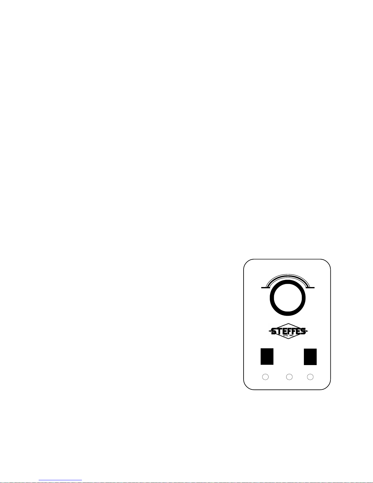
•Space Heating
Heating is accomplished both radiantly and by thermostatically
controlled fans. Radiant heat is the heat given off by the warm
room unit cabinet. If the radiant heat is not sufficient to satisfy
the rooms heat requirements, the on-board room temperature
thermostat located on the front panel of the unit will automatically cycle the unit's fan(s), circulating air through the ceramic
brick core and back into the room to maintain a constant
temperature. In installations where the heater is not the sole
source of heat for the home, the unit's fan(s) may be locked out
during some modes of operation. This lock-out allows the unit
to fully utilize it's storage capacity, reduce installation costs,
and obtain the highest efficiency possible.
EXT FACE PLATE
FIGURE 1
~ C~ C
~ C
~ C~ C
5555
55
5555
HEAHEA
HEA
HEAHEA
STORASTORA
STORA
STORASTORA
CHARGINGCHARGING
CHARGING
CHARGINGCHARGING
OMFOROMFOR
OMFOR
OMFOROMFOR
TT
T
TT
GEGE
GE
GEGE
OO
O
OO
OFFOFF
OFF
OFFOFF
NN
N
NN
Z Z
TT
T
Z
TT
Z Z
LOLO
W/AW/A
LO
W/A
LOLO
W/AW/A
OFF-PEAKOFF-PEAK
OFF-PEAK
OFF-PEAKOFF-PEAK
HIGHHIGH
HIGH
HIGHHIGH
UTOUTO
UTO
UTOUTO
MEDMED
MED
MEDMED
OO
O
OO
~ ~
NENE
NE
~
NENE
~ ~
CHARGECHARGE
CHARGE
CHARGECHARGE
LEVELLEVEL
LEVEL
LEVELLEVEL
OO
N-PEAKN-PEAK
O
N-PEAK
OO
N-PEAKN-PEAK
8585
85
8585
•Core Charging
Page 6
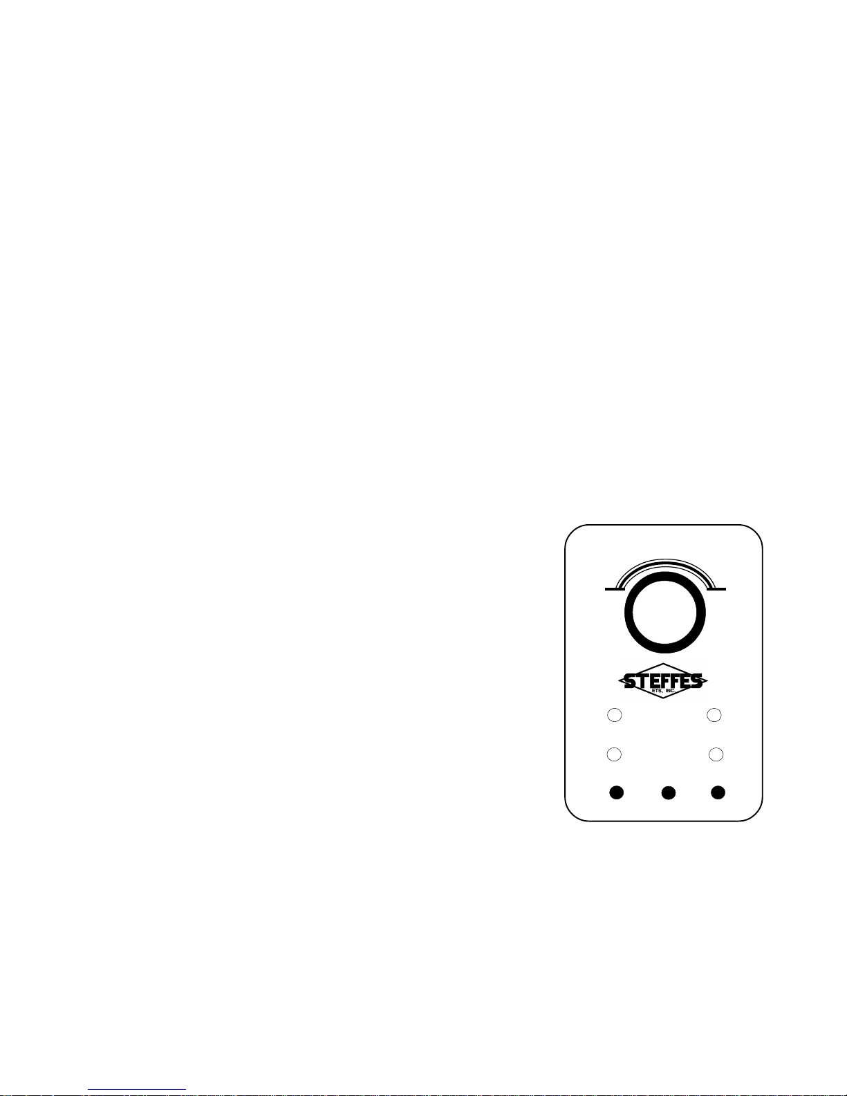
The EXT series can be configured in many ways. Due to the wide variety of setup methods and options, it
may be necessary to consult with your sales representative for the operation instructions of your
heating system.
Several control devices can be used for core charging. Different combinations of these devices will provide
for optimal unit function based upon utility needs, home characteristics, and installation requirements.
Rocker switches, if unit is equipped, are located on the front control panel and will vary the level of charge
that is stored in the unit's brick core. The HEAT STORAGE rocker switch can be set in the OFF position to
minimize the amount of heat stored or in the ON position to activate the CHARGE LEVEL rocker switch.
The CHARGE LEVEL switch can be placed in the LOW/AUTO position for applications using automatic
charge control. With the addition of this option, core temperature is automatically regulated in relation to
outdoor air temperature. Override of the automatic charge controller can occur by setting the CHARGE
LEVEL rocker switch to MEDIUM or HIGH.
Automatic charge control may also be configured without rocker switches. In these installations, core
temperature level is solely controlled by an outdoor air temperature sensor, by the utility, or self regulated
by the amount of heat being required to satisfy the room's requirements.
For applications without automatic charge control, LOW/AUTO position is normally used during the
early spring and late fall. Setting the CHARGE LEVEL switch to positions MEDIUM or HIGH will
increase charge levels for colder weather conditions.
•Overrides
Some units are equipped with override systems. These override
buttons, if the unit is equipped, are located on the front control
EXT FACE PLATE
WITH OVERRIDES
FIGURE 2
panel. The PEAK OVERRIDE button is for emergency heat only
~ C~ C
OMFOROMFOR
~ C
OMFOR
OMFOROMFOR
LoLo
Lo
LoLo
~ C~ C
ww
w
ww
(utility permitting) and will provide heating element operation during
peak times when pushed. The SENSOR OVERRIDE button will
override the outdoor air temperature sensor when pushed to increase
the charge level in anticipation of colder weather conditions within
the next twenty-four hour period. Both overrides are self-cancelling
or can be cancelled by the CANCEL OVERRIDE button.
An optional peak override wind-up timer is also available for peak
overrides. This timer is mounted on the side of the unit. The user
selects the override time which can vary from zero to six hours.
•Indicator Lights
Indicator lights signal the unit's operating mode to the user.
The green OFF-PEAK light illuminates during off-peak periods.
CHARGINGCHARGING
CHARGING
CHARGINGCHARGING
OO
VERRIDEVERRIDE
O
VERRIDE
OO
VERRIDEVERRIDE
--O--O
--O
--O--O
SENSORSENSOR
SENSOR
SENSORSENSOR
VERRIDEVERRIDE
VERRIDE
VERRIDEVERRIDE
The yellow CHARGING light illuminates whenever the elements
are charging usually during off-peak periods or during on-peak if the
PEAK OVERRIDE button is pushed. The red ON-PEAK light illuminates during on-peak periods
to indicate element control. If the unit is equipped with an override system, it will also have an
orange OVERRIDE light. This light illuminates whenever the PEAK OVERRIDE button or
SENSOR OVERRIDE button have been pushed.
TT
T
TT
PEAKPEAK
PEAK
PEAKPEAK
Z Z
Z
Z Z
OO
NENE
O
NE
OO
NENE
OO
N-PEAKN-PEAK
O
N-PEAK
OO
N-PEAKN-PEAK
OFF-PEAKOFF-PEAK
OFF-PEAK
OFF-PEAKOFF-PEAK
----
--
----
CANCELCANCEL
CANCEL
CANCELCANCEL
~ ~
~
~ ~
HiHi
Hi
HiHi
ghgh
gh
ghgh
Page 7
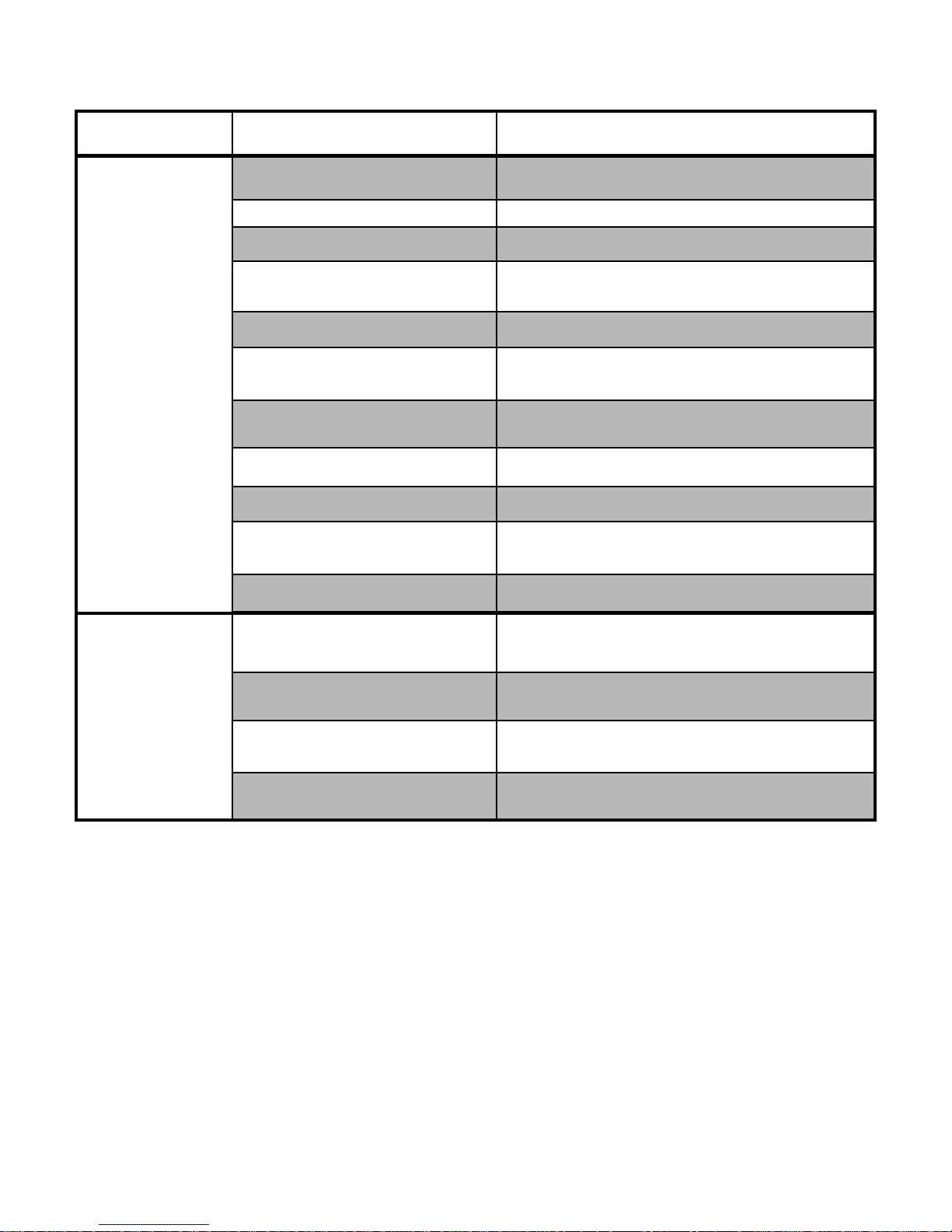
C. CONTROL DEVICES/SAFETY LIMIT DEVICES
Table 2
CATEGORY DEVICE NAME ACTION
Control Devices: Charge Control Thermostat/Switches Cycles charging elements to maintain a
Room Temperature Thermostat Cycles unit fan(s) to maintain space temperature.
Bimetallic Coil and Damper Assembly Modulates damper to maintain a preset
Charge Control Sequencer/Relay Stages elements "ON" to reduce load on
Charge Indicator Light Indicates heating elements are being energized.
(If unit is equipped.)
Time Clock -- Seven day programmable Monitors time and signals heating elements to charge
with Battery Back-Up during off-peak hours. Typically used in Time-of-Use
(Optional in EXT series only.) (TOU) utility rate strategies.
Peak Override Wind-up Timer Overrides peak signal to allow charging of heating
(Optional in EXT series only.) elements during a control period. (Emergency heat
Power Line Carrier Provides wireless control signals for utility on-peak
Utility Mode Timer Initiates a time-based on-peak period upon the
(Optional in EXT series only.) completion of a utility controlled charging period.
Peak Control Sequencer Monitors voltage of charging circuits to signal peak
(Optional in EXT series only.) conditions when line voltage interruption is used for peak
Low Voltage Control Module Provides low voltage control of element charging
(Optional in S series only.) and fan operation.
proper core charge level.
discharge temperature.
charge control thermostat.
(Used only on models 412, 512 & 612)
for a preset time initiated by user only.)
and off-peak periods.
control.
Safety Devices: Core Charging High Limit De-energizes heating elements if maximum core
Switch(es) temperature is exceeded. (Automatically resets when core
Discharge Fan High Limit Monitors discharge air temperature and de-energizes fan(s)
Switch(es) if maximum temperature is exceeded. (Automatically
Service Light Indicates the core charging high limit switch has
Tip Over Switch Disables heating elements and fan(s) if unit
(Units equipped with security is not in the upright position.
base only)
temperature decreases.)
resets when discharge air temperature decreases.)
interrupted power to the heating elements.
D. MAINTENANCE/CLEANING
As with most heating systems, air borne particles in the room may be drawn into the heating system and oxidized.
As these air borne particles are expelled back into the room, they may accumulate on the heater or other surfaces. Over
time, these particles may appear as a black residue, commonly referred to as soot. High concentrations of air borne
particles from such things as aerosols, dust, candles, incense, pet hair, high humidity, smoke or cooking can contribute to
poor indoor air quality and accelerate this process.
To minimize the black residue build up, clean the outer surface of the heater on an annual basis or as needed. Wash
the cabinet only when cool with any liquid cleaner. Do not use scouring powders or furniture polish. Steffes ETS
recommends using "Soft Scrub with Bleach" brand cleanser or equal. Regularly vacuum around all sides of the heater.
•Service Light
A red service light located in the bottom right corner of the grill (See Figure 6) will illuminate whenever the core
charging high limit is tripped. The illumination of the light may indicate violated clearances or possibly an operational
difficulty within the heater. The unit will function with the service light illuminated; however, long-term operation may
reduce the life expectancy of internal components. If the light illuminates repeatedly, notify a service technician.
Page 8
3. INSTALLATION
A. PLACEMENT
Room units can normally be placed on standard flooring systems with any type of covering, i.e., wood, carpet,
linoleum; but, heater weight must be considered. If in doubt, consult a building contractor or an architect. (See Table
3 for weight and physical dimensions of unit being installed.)
Room units are equipped with adjustable leveling legs or a security base. When installing a room unit with
adjustable leveling legs on carpet, adjust the legs so that carpet compression does not cause upward bowing of unit's
floor panel. Leg extension should not, however, exceed 3/4 inch overall. On extremely thick padded carpet, it may be
necessary to place the unit on a one inch nominal board, 8 3/4 inches wide and of appropriate length for the heating
unit being installed. Failure to follow these guidelines could result in damage to the flooring.
B. CLEARANCE REQUIREMENTS
Allow 1 5/8 inches clearance from the sides and back of the heater, and a minimum of four inches from the top
of the heater. The factory supplied wall mounting bracket, located on the heater's shipping pallet, will provide the
correct wall to back of heater clearance. If the heater is a 120V plug-in model with a security base, the base will
provide the proper wall to back of the heater clearance. If enclosing the S Series unit in a wooden cabinet or recessing
unit into a wall, allow two inches clearance on sides and four inches on top. Do not enclose or otherwise obstruct
access to the heaters's front panel and grill. It is not recommended to recess or enclose an EXT Series unit as it may
cause some inaccuracy in room thermostat operation. All objects must be kept a minimum of four inches from all unit
surfaces and 15 inches from the grill.
(NOTE: For ease of servicing the EXT series unit, a clearance of 12" on the right side
of unit is recommended.)
C. SET-UP PROCEDURE
GENERAL NOTE:
A. For cross reference to number coded components,
see Figure 7 (S series) or Figure 8 (EXT series).
•Room Unit and Site Preparation
1. Remove control knob (44), if unit is equipped, grill (46) and grill
support bracket (22) from unit.
(NOTE: If unit being installed is equipped with a security
base, skip to Step 4.)
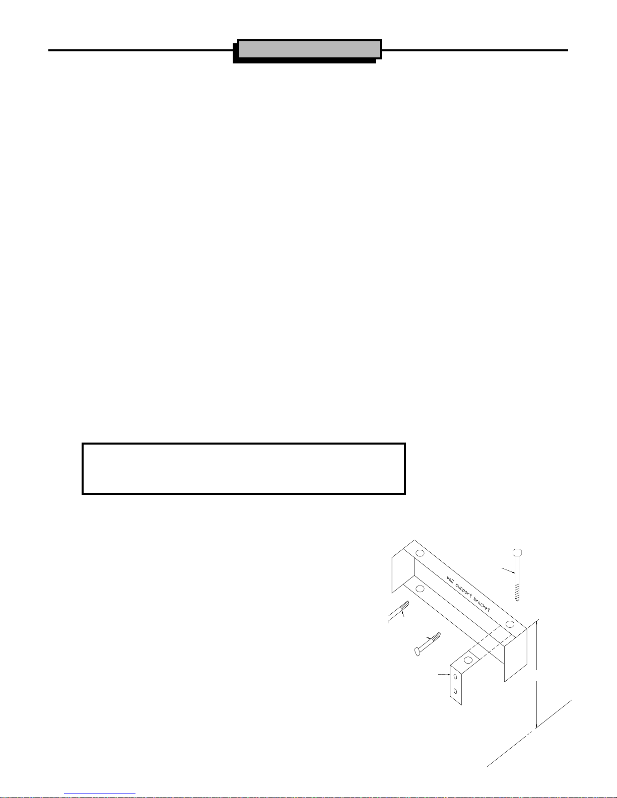
2. Establish unit location and attach wall support bracket (1) to
wall using the lag bolts provided. (See Figure 3). The wall
support bracket is shipped on the pallet under the room unit. A
plastic bag containing the wall support bracket hardware kit (58)
is provided inside the lower fan cavity. The top of the bracket
should be 26" from the floor.
attached to studs
wall support clip
WALL ATTACHMENT
lag bolts
FIGURE 3
bolt
26"
(NOTE: The lag bolts must attach to wood wall studs. If the
wall is not a standard wood studded structure,
alternate fasteners must be used to securely attach
the wall bracket.)
floor
Page 9
3. Attach 1 3/4" x 1 5/8" wall support clips (31) to upper back side of unit using #8 x 1/2" sheet metal
screws provided in hardware kit. Use the carriage bolts to secure the room heating unit to the wall
support bracket.
4. Install field connection junction box. (If installing a 120 volt plug-in unit, skip to Electrical Connections
section.)
(NOTES: 1. Where possible, flush mount using a Sylvania #2002-R-C or equal.
If unavoidable, surface mount using a Steel City #72151 - 1/2 + 3/4
or equal. Mount at floor level. Line voltage field wire must be
rated for 75
0
C minimum.
2. Different wiring methods and unit sizes necessitate larger junction
boxes than specified above. Check State and National Electrical
Codes for proper junction boxes.)
•Electrical Connections
1. For wiring connections, refer to Figure 10, 11, 12, or 13.
(NOTE: If installing an EXT series unit, skip to Step 3.)
2. All S series units are equipped for automatic charge control. If these units are to be controlled manually,
insulate the orange umbilical cord wires at the junction box.
3. Check the unit identification label for correct voltages and wattages.
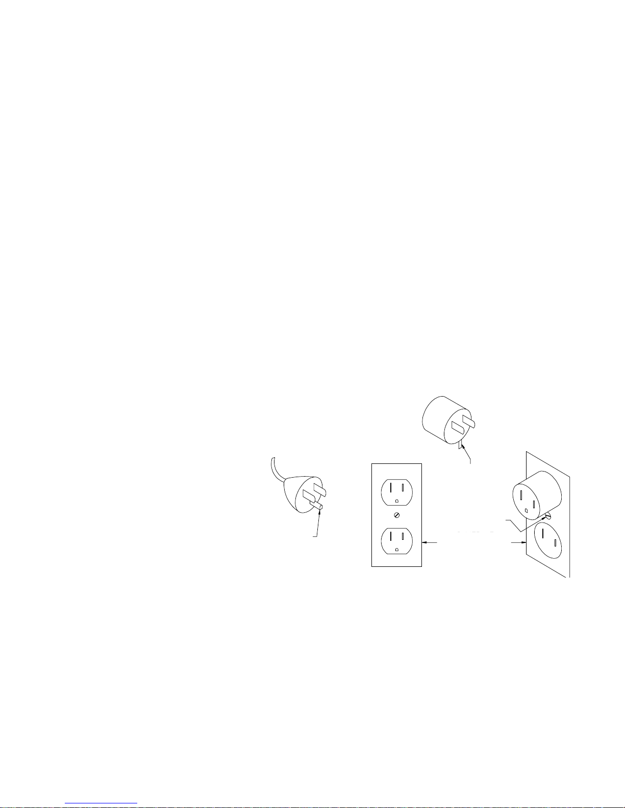
(NOTE: For 120 volt plug-in units, see Figure 2.)
This heater is for use on 120 volts. The
cord has a plug as shown at Figure 4A. An
adapter as shown in Figure 4C is available for connecting three blade grounding type plugs to two slot receptacles. The
green grounding lug extending from the
adapter must be connected to a permanent ground such as a properly grounded
outlet box. The adapter should not be
used if a three slot grounded receptacle is
available.
4. Upon completing electrical connections,
CORD CONNECT
FIGURE 4
grounding pin
Fig 4A
adapter
grounding means
Fig 4C
grounding screw
grounded outlet
box
Fig 4B
move room unit into position and secure
wall support clips (31) to wall support
bracket (1) with 1/4" x 2" bolts provided. Omit this step if installing a unit equipped with a security base.
5. If unit is equipped with leveling legs (17) adjust prior to brick loading. If installing a unit equipped with a
security base (72), this base must be secured to unit prior to loading the brick or putting the unit into
operation. Remove the 5/16" X 1 1/2" bolts from the bottom of the unit. Attach base by inserting these
bolts through the base and screwing back into the same threaded openings they were removed from.
(NOTE: For safety and ease of servicing, label all charging and control circuits in the distribution
panel with the orange panel label provided in the wall support bracket hardware kit (58) .)
Page 10
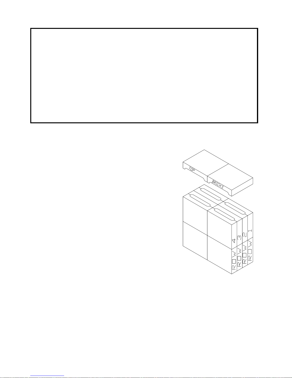
•Brick Loading
GENERAL NOTES:
A. Room Units and ceramic heat storage bricks (13) are packed separately. The bricks are
shipped in boxes of four (white box) and boxes of five (brown box). One box of each is
required per element bay or nine bricks total. Refer to Table 3 for the total number of
bricks required in model being installed.
B. All bricks for the Steffes ETS room units are identical. One side of the brick is indented to
accommodate the factory installed heating elements. Bricks are inserted in rows four deep
and two high. Bricks are “loaded” by maneuvering them around the elements taking care to
bend elements as little as possible.
CAUTION: Use NIOSH/MSHA approved respirator, gloves, and long sleeved garments
when handling insulation materials in accordance with generally accepted
safety practices.
1. Remove hex head sheet metal screws at lower edge of
front panel (4); pull panel outward and down to
detach.
2. Lift 1/2" white blanket-type insulation (5) up and
drape over top of unit.
3. Remove front aluminized steel (8).
(NOTE: To catch brick debris and to protect the
flooring, we recommend laying the unit
shipping box in front of the unit before
loading the brick.)
4. Begin brick loading with Row 1 starting with the right
side and working toward left. Follow with the upper
layer of the back row in the same manner. Make sure
that all bricks are flush with the back aluminized steel
(9) and the brick indentation is facing the front of the
unit (See Figure 5).
5. Next, load Rows 2 and 3 using the same method
reversing brick indentation as required to
accommodate heating elements (54). Again,
make certain all bricks fit flush against the
previous rows of brick.
BRICK STACKING
FIGURE 5
Page 11
6. After loading Row 3, insert a
row of bricks on top with the
indentation facing down.
Continue with Row 4 starting
with a lower brick followed by
the upper brick.
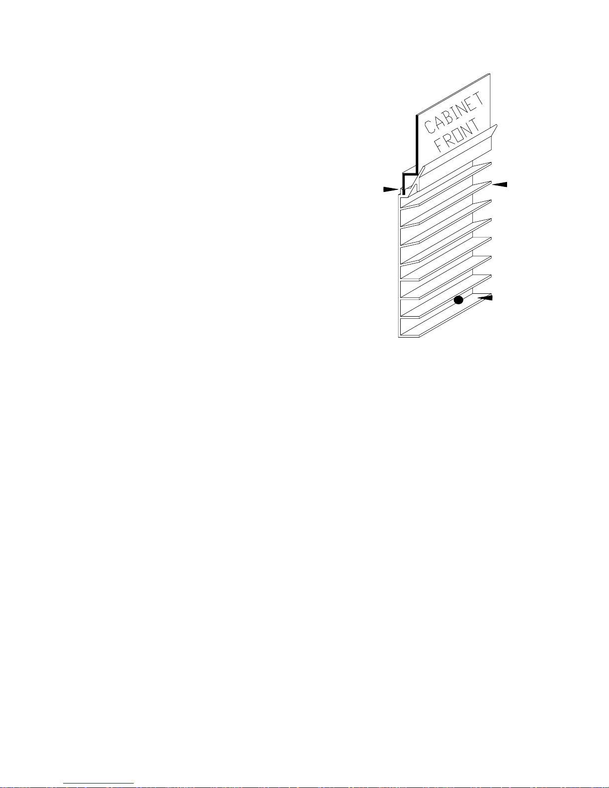
7. Return the front aluminized
steel (8) to position.
GRILL ATTACHMENT
FIGURE 6
8. Carefully replace 1/2" blanket
insulation (5) making sure all
edges fit snugly.
GRILL MUST
ATTACH
TO FRONT PANEL
9. Install front panel (4) using hex
head sheet metal screws at lower edge.
10. Vacuum lower portion of the unit.
11. Make sure fan impellers (53) turn freely.
12. Manually open air mixing damper by depressing
bimetallic coil (39) to check for freedom of operation
and absence of debris.
13. Reassemble the unit (See Figure 6).
14. Complete Owner Registration Card and return to Steffes ETS, Inc.
(NOTE: Serial number information can be found in several places:
1. Unit shipping box
2. Label on lower right side panel of unit
3. Blue and Silver listing label on bottom panel inside the fan compartment.
4. The Owner Registration Card provided with the manual has been labeled with
unit serial number information at the factory.)
AS SHOWN
GRILL
SERVICE
LIGHT
•ROOM THERMOSTAT INSTALLATION
EXT units come standard with an on-board low voltage room temperature thermostat mounted on the front panel.
For units not equipped with on-board thermostat (S or EXT series), mount room thermostat on an interior wall near the
room entrance at a height of five feet from floor level. Choose location to ensure thermostat will be unaffected by drafts,
sunlight, or other sources of heat or cold.
Line or low voltage thermostats are available. If line voltage is desired, order Steffes thermostat #1300000. If low
voltage is desired, order Steffes low voltage thermostat item #1300002 which provides low voltage control of fan operation;
however, low voltage contact is required for element control. Steffes thermostat, item #1300007 has a built in clock which
provides low voltage control of element charging and fan operation with no other element control device required. On S series
units, both low voltage thermostats must be used in conjunction with the Steffes low voltage control module, item #1300004.
Page 12
4. APPENDIX
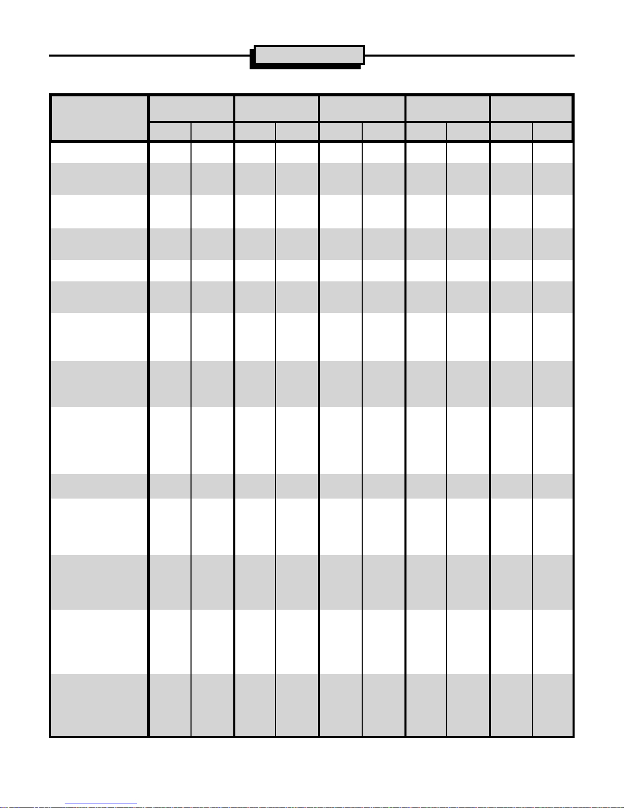
A. UNIT SPECIFICATIONS - TABLE 3
212 312 412 512 612
MODEL
S EXT S EXT S EXT S EXT S EXT
Length - inches 22 28 30 36 38 44 46 52 54 60
Height - inches 27.5 27.5 27.5 27.5 27.5 27.5 27.5 27.5 27.5 27.5
Depth - inches 9.75 9.75 9.75 9.75 9.75 9.75 9.75 9.75 9.75 9.75
(w/out wall bracket)
Number of Bricks 18 18 27 27 36 36 45 45 54 54
Weight of Bricks-lbs 182 182 273 273 364 364 455 455 546 546
Installed Weight-lbs 255 262 365 372 480 487 592 599 706 713
*Element Voltage-Std.240240240240 240240240240240240
(277V & 208V opt. all
series 120 V opt. EXT
series, 1.32 kW maximum)
*Fan Voltage - Std. 230 230 230 230 230 230 230 230 230 230
(Standard output -
115, 208 & 277 opt.)
(High output - 115 opt.)
*Chg Ctrl Resistor
Wattage 12.8 N/A 12.8 N/A 12.8 N/A 12.8 N/A 12.8 N/A
Voltage 240 N/A 240 N/A 240 N/A 240 N/A 240 N/A
(Consult factory for optional
voltages.)
Number of Fans 1111 222222
Fan Wattage - each
Standard Output 12 12 28 28 15 15 15 15 28 28
High Output N/A 80 N/A 80 N/A 80 N/A N/A N/A N/A
On-Peak Capacity
kWh 13.5 13.5 20.25 20.25 27 27 33.75 33.75 40 40
BTU 46,062 46,062 69,093 69,093 92,124 92,124 115,155 115,155 136,480 136,480
Max. Daily Output
8 hour charge ** ** ** ** **
kWh 19 24 29 36 38 48 48 60 58 72
BTU 64,828 81,888 98,948 122,832 129,656 163,770 163,776 204,720 197,896 245,664
Max. Daily Output
12 hour charge ** ** ** ** **
kWh 29 36 43 54 58 72 72 90 86 108
BTU 98,948 122,832 146,716 184,248 197,896 245,664 245,664 307,080 293,432 368,496
*See Unit Identification label on lower right side panel of unit for proper voltages.
**With 1500 watt elements and high output fans.
Page 13
B. WIRING
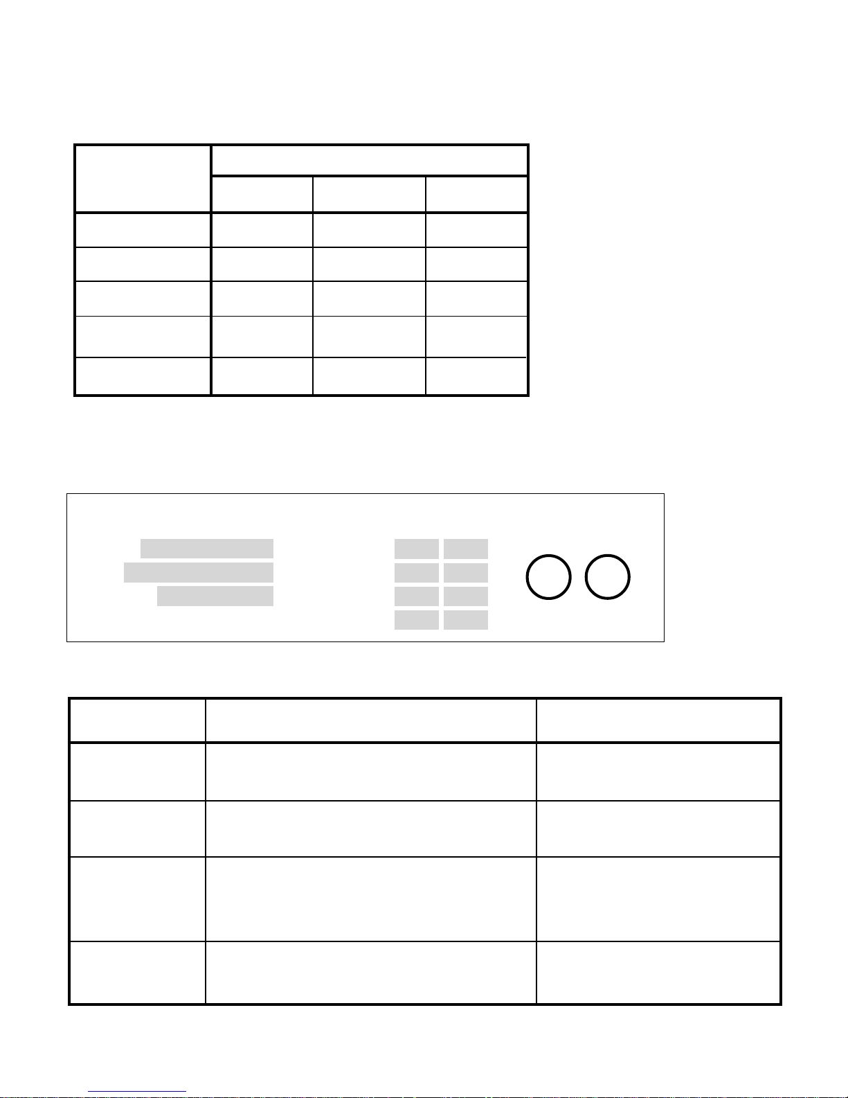
FIELD CONNECTION WIRING
TABLE 4
WIRE
SIZE
#14 AWG 2.8 3.3 2.4
#12 AWG 3.8 4.4 3.3
#10 AWG 5.7 6.6 4.9
#8 AWG 7.6 8.8 6.6
#6 AWG 11.5 13.2 9.9
Use copper wire rated at 75oC minimum, only.
UNIT IDENTIFICATION LABEL
Steffes ETS, Dickinson, NDSteffes ETS, Dickinson, ND
Steffes ETS, Dickinson, ND
Steffes ETS, Dickinson, NDSteffes ETS, Dickinson, ND
Manufactured in U.S.A.
Model Charge Crct #1
240VAC 277VAC 208VAC
FIGURE 7
MAXIMUM kW
VACVAC
VAC
VACVAC
WattsWatts
Watts
WattsWatts
NOTES:
1. 512 and 612, S and EXT series
units, are equipped with a two
circuit element feed option. If
dual feed is used, see unit identification label located on right
side panel for proper sizing of
each circuit. Charge Circuit #1 +
Charge Circuit #2 = Total Wattage.
2. The field connection wire size
guide reflects only the code interpretation of Steffes ETS. It is the
responsibility of the installer to
follow all applicable codes and
regulations for the installation.
ElectricElectric
Electric
ElectricElectric
Air HeaterAir Heater
Air Heater
Air HeaterAir Heater
S/N Charge Crct #2
Options Fan/Cntrl Crct
U.S. Patent #5.042.081U.S. Patent #5.042.081
U.S. Patent #5.042.081 Temp Cntrl Crct
U.S. Patent #5.042.081U.S. Patent #5.042.081
U
UNIT WIRING
TABLE 5
U
L
C
LISTEDLISTED
LISTED
LISTEDLISTED
3P233P23
3P23
3P233P23
L
WIRE COLOR CONNECTION TERMINALS CIRCUIT DESCRIPTION
Black L1 and L2 terminals on main terminal block. Right heating element
circuit. (Charge circuit #1)
Red L1 and L2 terminals on auxilliary terminal block. Left heating element
(512 and 612 units only) circuit. (Charge circuit #2)
Blue F1 and F2 terminals on main terminal block Fan and control circuit.
with S series only. F1 and F3 terminals on main
terminal block with EXT series only.
Orange A1 and A3 terminals on main terminal block Automatic charge
with S series only. control circuit.
See Unit Identification Label on lower right side of unit for proper fan and element voltages.
Page 14
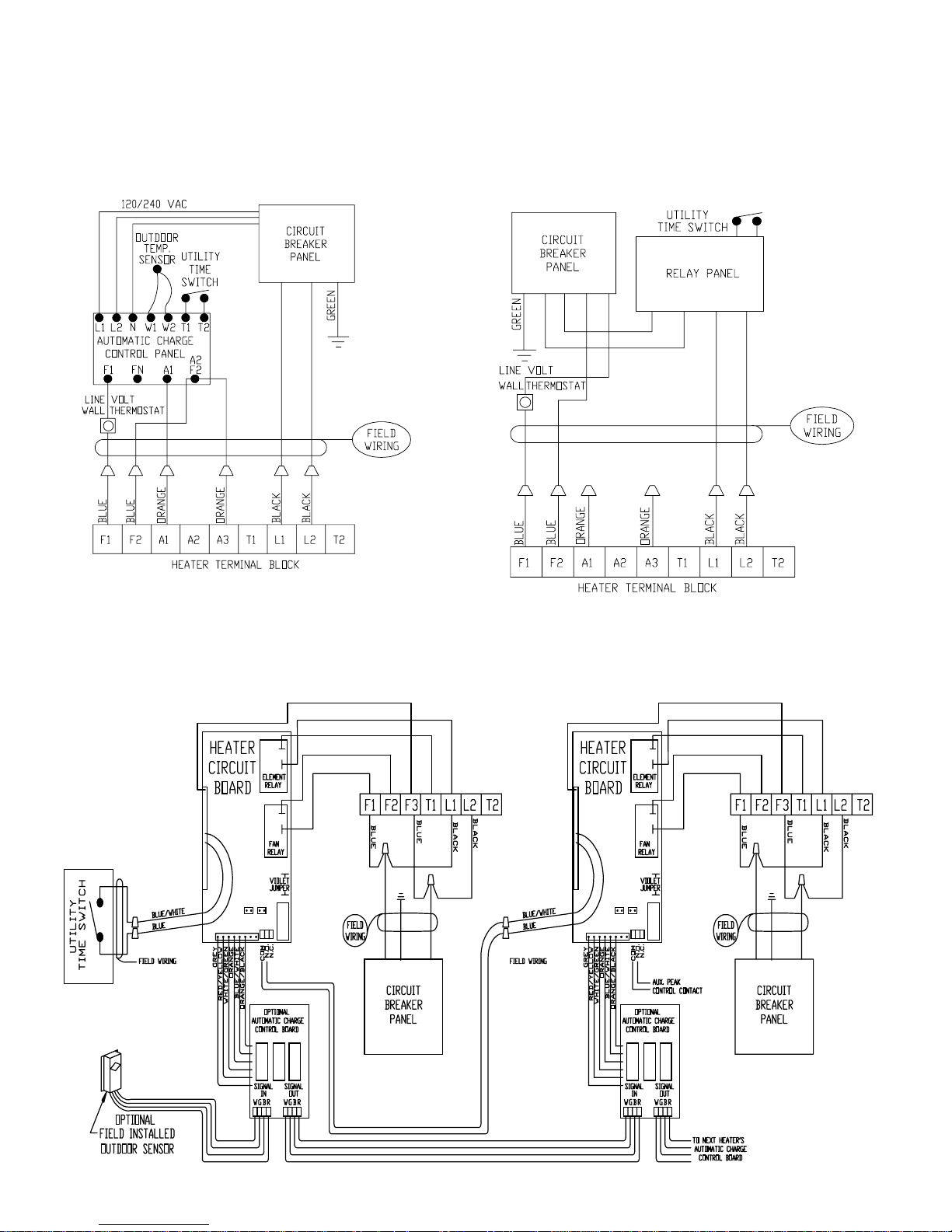
TYPICAL SYSTEM WIRING DIAGRAMS
Connections shown are for 230 VAC fans.
See Unit Identification Label on lower right side panel of unit for proper fan and element voltages.
(Refer to the Face Plate Diagrams to determine which circuit board your heater incorporates.)
S Series - Automatic Charge Control S Series - Manual Charge Control
FIGURE 8 FIGURE 9
INSULATE ORANGE
WIRES
(SEE NOTE #1 AND #2)
EXT Series - Automatic or Manual Charge Control
(shown with two-mode circuit board)
FIGURE 10
HEATER #1
HEATER #2
Page 15
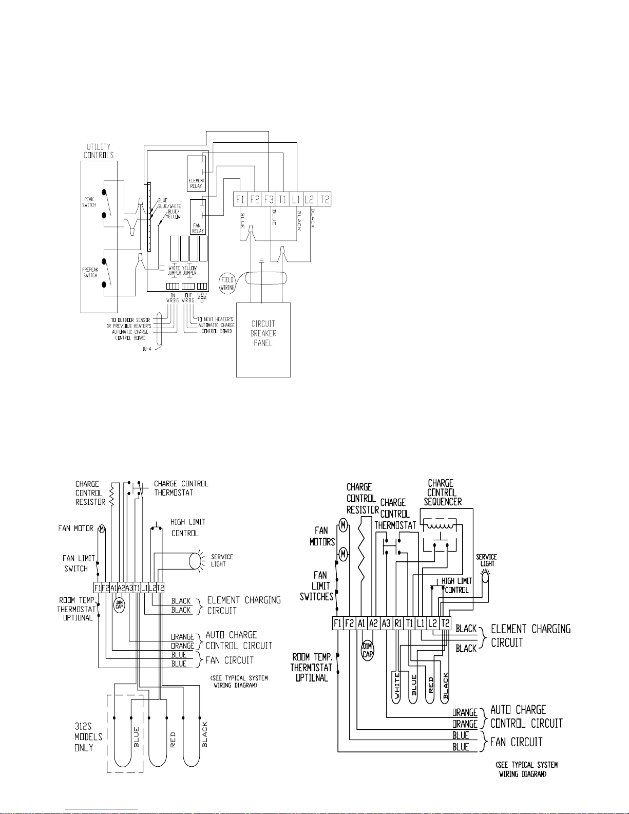
TYPICAL SYSTEM WIRING DIAGRAMS CONTINUED...
Connections shown are for 230 VAC fans.
See Unit Identification Label on lower right side panel of unit for proper fan and element voltages.
(Refer to the Face Plate Diagrams to determine which circuit board your heater incorporates.)
EXT Series - Automatic or Manual Charge Control
(shown with multi-mode circuit board)
FIGURE 11
NOTES FOR FIGURES 10 & 11:
#1: Never apply any external voltage to
the Blue and Blue/White Low Voltage Conductors.
#2: Peak Control Sequencer cannot be used
if utility time switch is connected to Blue
(SEE NOTE #1 AND #2)
and Blue/White wires.
UNIT WIRING DIAGRAMS - S SERIES
Connections shown are for 230 VAC fans.
See Unit Identification Label on lower right side panel of unit
for proper fan and element voltages.
Models: 212S - 312S Model: 412S
FIGURE 12 FIGURE 13
Page 16
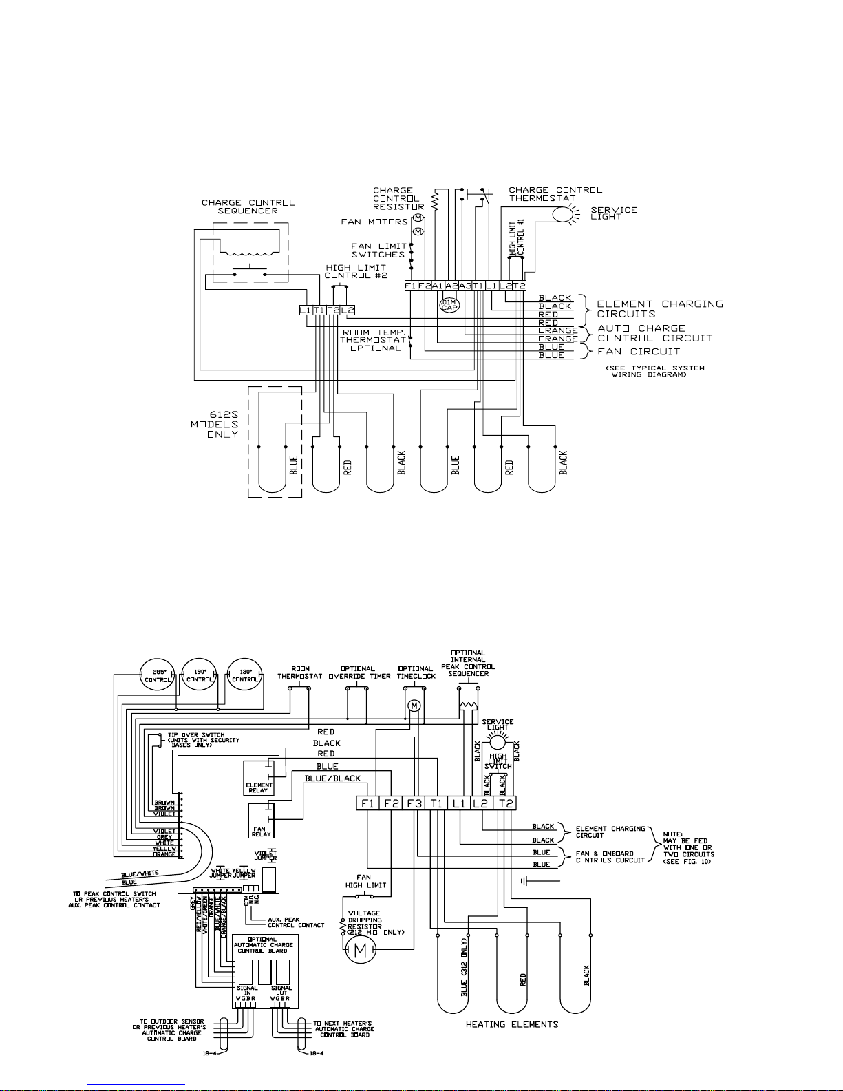
UNIT WIRING DIAGRAMS - S SERIES CONTINUED. . .
Connections shown are for 230 VAC fans - See Unit Identification Label on lower right side panel of unit
for proper fan and element voltages.
(Refer to the Face Plate Diagrams to determine which circuit board your heater incorporates.)
Models: 512S - 612S
FIGURE 14
UNIT WIRING DIAGRAMS - EXT SERIES
Connections shown are for 230 VAC fans.
See Unit Identification Label on lower right side panel of unit for proper fan and element voltages.
(Refer to the Face Plate Diagrams to determine which circuit board your heater incorporates.)
Models: 212EXT - 312EXT
(shown with two-mode circuit board)
FIGURE 15
NOTES FOR FIGURE 15:
1. See Typical System Wiring Diagram.
2. Use this method of control when the element
charging circuit is being interrupted with a low
voltage dry contact signal. Do not parallel blue
and blue/white wires, from multiple heaters to
a single switch. (See Typical System Wiring
Diagram.)
3. If you are controlling the element charging
circuit directly rather than with low voltage, a
peak control sequencer device (see Table 2)
should be used.
Page 17
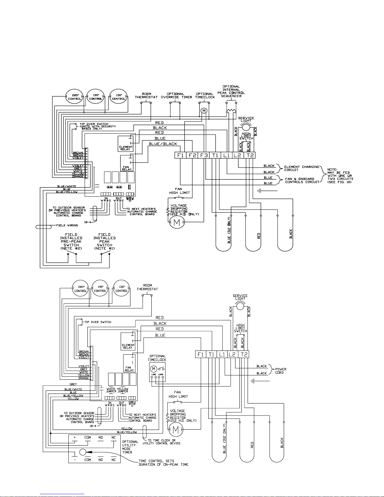
UNIT WIRING DIAGRAMS - EXT SERIES CONTINUED . . .
Connections shown are for 230 VAC fans.
See Unit Identification Label on lower right side panel of unit for proper fan and element voltages.
(Refer to the Face Plate Diagrams to determine which circuit board your heater incorporates.)
Models: 212EXT - 312EXT
(shown with multi-mode circuit board)
FIGURE 16
NOTES FOR FIGURE 16:
1. If peak switch is open, no charging can occur.
2. If the pre-peak switch is open,
the elements will charge to a
level based on outdoor temperature. If the pre-peak switch is
closed, the elements will charge
for the duration of heat calls
only.
Models: 212EXT - 312EXT
(shown with multi-mode circuit board
and 120 Volt cord connected)
FIGURE 17
Page 18
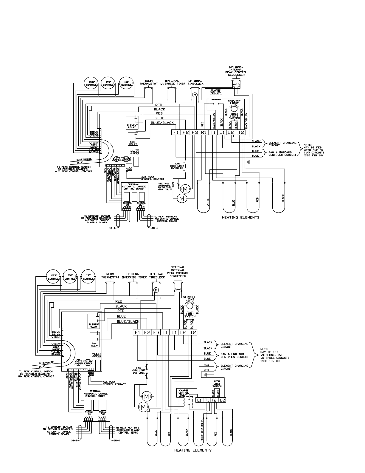
UNIT WIRING DIAGRAMS - EXT SERIES CONTINUED. . .
Connections shown are for 230 VAC fans.
See Unit Identification Label on lower right side panel of unit for proper fan and element voltages.
(Refer to the Face Plate Diagrams to determine which circuit board your heater incorporates.)
Model: 412EXT
(shown with two-mode circuit board)
FIGURE 18
(SEE NOTE #1)
(SEE NOTE #2)
(SEE NOTE #2)
Models: 512EXT - 612EXT
(shown with two-mode circuit board)
FIGURE 19
NOTES FOR FIGURES 18 & 19:
1. See Typical System Wiring Diagram.
2. Use this method of control when the
element charging circuit is being interrupted with a low voltage dry contact
signal. Do not parallel blue and blue/
white wires from multiple heaters to a
single switch. (See Typical System Wiring Diagram.)
3. If you are controlling the element charging circuit directly rather than with low
voltage, a peak control sequencer device
(see Table 2) should be used.
(SEE NOTE #1)
Page 19
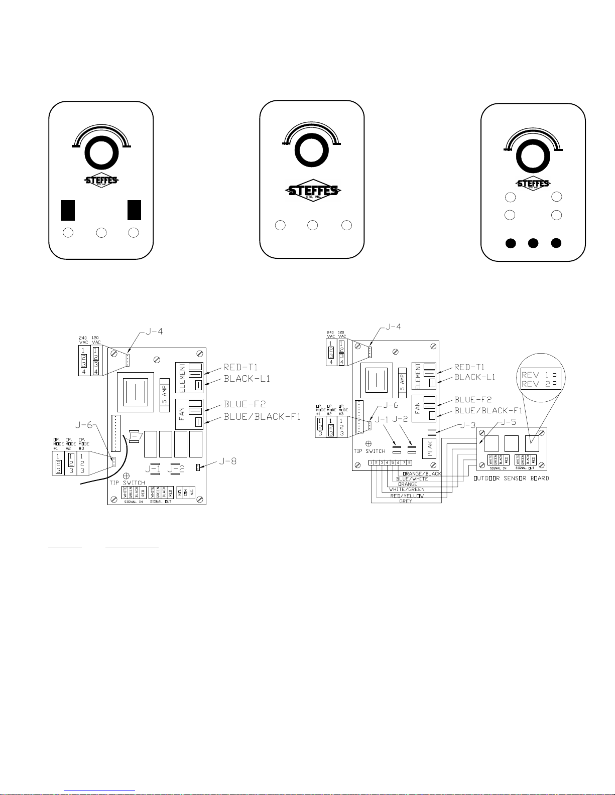
CIRCUIT BOARD FACE PLATES - EXT SERIES
(NOTE: When reading the Typical System Wiring Diagrams and Unit Wiring Diagrams, use
these skematics to determine which circuit board your heater incorporates.)
TWO-MODE
FIGURE 20
~ C~ C
OMFOROMFOR
~ C
OMFOR
OMFOROMFOR
~ C~ C
5555
55
5555
HEAHEA
TT
HEA
T
HEAHEA
TT
STORASTORA
GEGE
STORA
GE
STORASTORA
GEGE
OO
NN
O
N
OO
NN
LOLO
LO
LOLO
OFFOFF
OFF
OFFOFF
OFF-PEAKOFF-PEAK
CHARGINGCHARGING
CHARGING
CHARGINGCHARGING
OFF-PEAK
OFF-PEAKOFF-PEAK
Multi-Mode Circuit Board Configurator
MULTI-MODE
FIGURE 21
TT
T
TT
W/AW/A
W/A
W/AW/A
Z Z
Z
Z Z
OO
O
OO
HIGHHIGH
HIGH
HIGHHIGH
UTOUTO
UTO
UTOUTO
MEDMED
MED
MEDMED
NENE
NE
NENE
8585
85
8585
CHARGECHARGE
CHARGE
CHARGECHARGE
LEVELLEVEL
LEVEL
LEVELLEVEL
OO
N-PEAKN-PEAK
O
N-PEAK
OO
N-PEAKN-PEAK
~ ~
~
~ ~
~ C~ C
~ C
~ C~ C
5555
55
5555
CHARGINGCHARGING
CHARGING
CHARGINGCHARGING
OMFOROMFOR
OMFOR
OMFOROMFOR
OFF-PEAKOFF-PEAK
OFF-PEAK
OFF-PEAKOFF-PEAK
Z Z
~ ~
TT
OO
NENE
T
Z
O
NE
~
TT
OO
NENE
Z Z
~ ~
8585
85
8585
OO
N-PEAKN-PEAK
O
N-PEAK
OO
N-PEAKN-PEAK
CHARGE CONTROL CIRCUIT BOARD CONFIGURATORS - EXT SERIES
Two-Mode Circuit Board Configurator
FIGURE 23
FIGURE 24
VARIABLE CHARGE
FIGURE 22
~ C~ C
~ C
~ C~ C
LoLo
ww
Lo
w
LoLo
ww
CHARGINGCHARGING
CHARGING
CHARGINGCHARGING
OO
O
OO
VERRIDEVERRIDE
VERRIDE
VERRIDEVERRIDE
SENSORSENSOR
SENSOR
SENSORSENSOR
OMFOROMFOR
OMFOR
OMFOROMFOR
--O--O
VERRIDEVERRIDE
VERRIDE
--O
VERRIDEVERRIDE
--O--O
PEAKPEAK
PEAK
PEAKPEAK
Z Z
TT
T
Z
TT
Z Z
OO
NENE
O
NE
OO
NENE
OO
N-PEAKN-PEAK
O
N-PEAK
OO
N-PEAKN-PEAK
OFF-PEAKOFF-PEAK
OFF-PEAK
OFF-PEAKOFF-PEAK
----
--
----
CANCELCANCEL
CANCEL
CANCELCANCEL
HiHi
Hi
HiHi
~ ~
~
~ ~
ghgh
gh
ghgh
Jumper Connections
J-1 Connected with a jumper in all modes except when using automatic charge control with two-mode circuit boards.
J-2 Always connected with jumper.
J-3 Connected with violet jumper except when fans are to be disabled during the charge period.
J-4 Input voltage selector: When fan circuit input voltage is 208-240 VAC,
J4-2 to J4-3 are connected. When fan circuit input voltage is 120 VAC, J4-1 to J4-2 and J4-3 to J4-4 are connected.
J-5 Factory wired with plug-in header connector.
J-6 Fan run time based charging jumper: In OP. MODE #1, off-peak heat call can bring core to a 1/3 charge level when no
other charging method is being used. OP. MODE #2 will allow off-peak heat calls to bring core to full charge. OP. MODE
#3 will not allow core charging based on fan run time (positive off).
J-7 24 VDC output from circuit board used for auxiliary control devices or to run peak and pre-peak signals on DC power
rather than AC power.
J-8 When connected, enables fans during pre-peak charging mode.
Jumper Configurations
Page 20
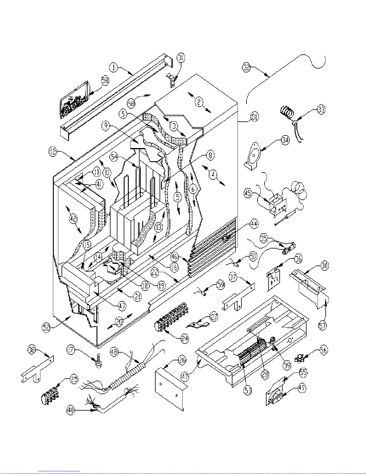
C. EXPLODED VIEW DIAGRAM - S SERIES
FIGURE 25
(Note: Refer to the Room Unit Parts List for part descriptions and order item numbers.)
Page 21
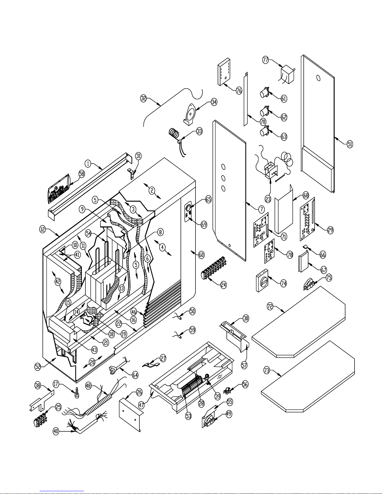
D. EXPLODED VIEW DIAGRAM - EXT SERIES
FIGURE 26
(Note: Refer to the Room Unit Parts List for part descriptions and order item numbers.)
Page 22
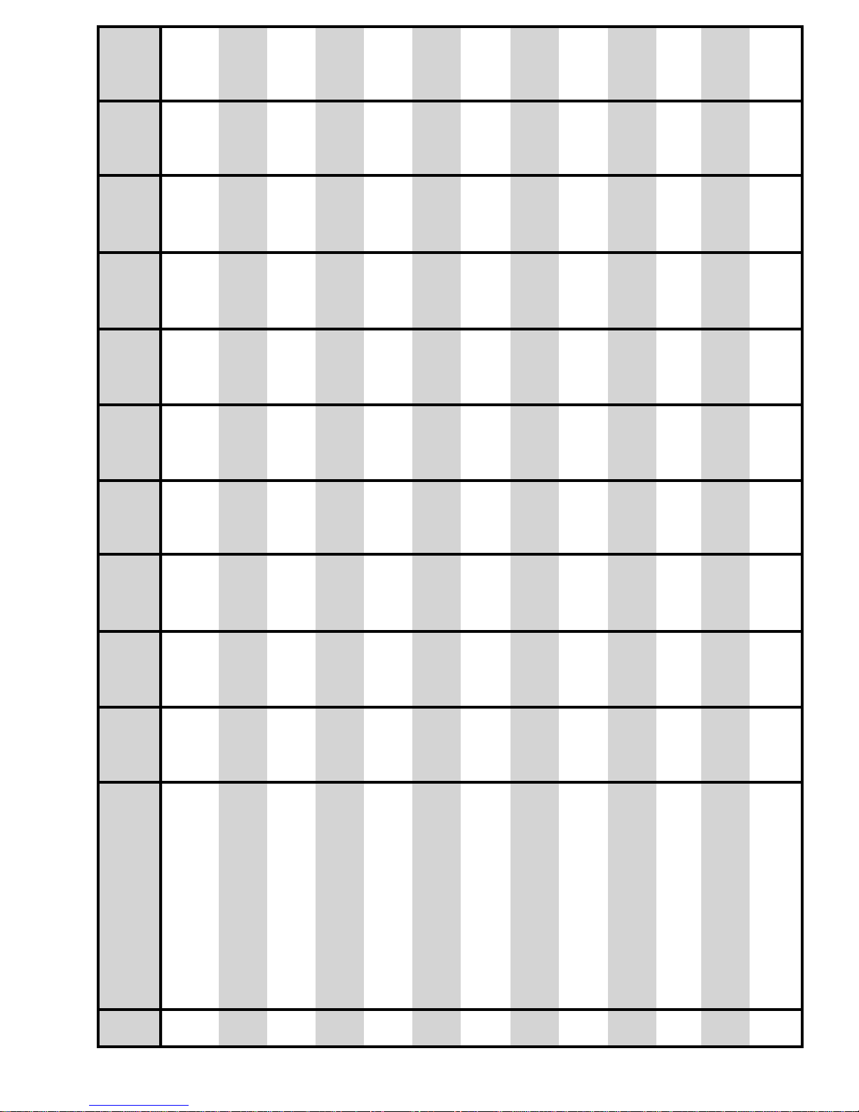
Refer to Exploded View Diagrams for Drawing Reference Number.)
E. ROOM UNIT PARTS LIST - S AND EXT SERIES - TABLE 6
(Note: When ordering replacement parts, please include unit model number and serial number.
1 Wall Support Bracket 1141010 1142000 1141012 1142001 1141014 1142002 1141016 1142003 1141018 1142004
2 Painted Panel, Top 1141142 1142010 1141143 1142011 1141144 1142012 1141145 1142013 1141146 1142014
3 1" Blanket Insulation, Top 1050010 1050010 1050011 1050011 1050012 1050012 1050013 1050013 1050014 1050014
4 Painted Panel, Front 1141147 1141147 1141148 1141148 1141149 1141149 1141150 1141150 1141151 1141151
5 1/2" Insulation Blanket, Front & Top 1050020 1050020 1050021 1050021 1050022 1050022 1050023 1050023 1050024 1050024
6 Insulation Panel, Front 1053000 1053000 1053002 1053002 1053004 1053004 1053006 1053006 1053008 1053008
NO. DESCRIPTION ITEM # ITEM # ITEM # ITEM # ITEM # ITEM # ITEM # ITEM # ITEM # ITEM #
REF. 212S 212EXT 312S 312EXT 412S 412EXT 512S 512EXT 612S 612EXT
DWG.
7 Mid Side Panel N/A 1142045 N/A 1142045 N/A 1142045 N/A 1142045 N/A 1142045
8 Aluminized Steel, Front 1140002 1140002 1140004 1140004 1140006 1140006 1140008 1140008 1140010 1140010
9 Aluminized Steel, Back & Top 1140012 1140012 1140014 1140014 1140016 1140016 1140018 1140018 1140020 1140020
10 Aluminized Steel Side 1142050 1142050 1142050 1142050 1142050 1142050 1142050 1142050 1142050 1142050
11 Insulation Panel, Back 1053000 1053000 1053002 1053002 1053004 1053004 1053006 1053006 1053008 1053008
12 Painted Panel, Back 1141135 1142020 1141136 1142021 1141137 1142022 1141138 1142023 1141139 1142024
13 Heat Storage Brick 1093007 1093007 1093007 1093007 1093007 1093007 1093007 1093007 1093007 1093007
14 Brick Support Insulation, Back 1052000 1052000 1052001 1052001 1052002 1052002 1052003 1052003 1052004 1052004
15 Brick Support Insulation, Center 1052011 1052011 1052012 1052012 1052013 1052013 1052014 1052014 1052015 1052015
16 Brick Support Insulation, Front 1052016 1052016 1052017 1052017 1052018 1052018 1052019 1052019 1052020 1052020
17 Leveling Leg 1159003 1159003 1159003 1159003 1159003 1159003 1159003 1159003 1159003 1159003
Element Tray Cover, Left N/A N/A N/A N/A 1141094 1141094 1141098 1141098 1141096 1141096
18 Element Tray Cover, Right (Std Output) 1141092 1142092 1141096 1141096 1141094 1141094 1141094 1141094 1141096 1141096
19 Element Tray (Std Output) 1141116 1141116 1141118 1141118 1141120 1141120 1141122 1141122 1141124 1141124
20 Painted Panel, Bottom 1141032 1142030 1141034 1142031 1141036 1142032 1141038 1142033 1141040 1142034
21 Brick Support Assembly (Std Output) 1141106 1141106 1141108 1141108 1141110 1141110 1141112 1141112 1141114 1141114
22 Grill Support Bracket 1141001 1142070 1141003 1142071 1141005 1142072 1141007 1142073 1141009 1142074
23 Room Thermostat Kit N/A 1190114 N/A 1190114 N/A 1190114 N/A 1190114 N/A 1190114
24 Terminal Block Kit (Main) 1040063 1040240 1040063 1040240 1040064 1040240 1040063 1040240 1040063 1040240
25 Terminal Block Kit (Aux) N/A N/A N/A N/A N/A N/A 1040062 1040062 1040062 1040062
26 Fan Support Bracket 1140220 1140220 1140220 1140220 1140220 1140220 1140220 1140220 1140220 1140220
27 Element Retainer 1141104 1141104 1141104 1141104 1141104 1141104 1141104 1141104 1141104 1141104
28 Bimetallic Linkage 1140001 1140001 1140001 1140001 1140001 1140001 1140001 1140001 1140001 1140001
30 Center Fan Track Assembly N/A N/A N/A N/A N/A N/A 1140242 1040242 N/A N/A
*29 Charge Control Circuit Board N/A * N/A * N/A * N/A * N/A *
" High Limit Guide Tube, Left N/A N/A N/A N/A N/A N/A 1105009 1105009 1105010 1105010
31 Wall Support Clip 1141020 1141020 1141020 1141020 1141020 1141020 1141020 1141020 1141020 1141020
32 High Limit Guide Tube, Right 1105005 1105005 1105006 1105006 1105007 1105007 1105008 1105008 1105011 1105011
33 Core Charging High Limit 1012000 1012000 1012000 1012000 1040056 1040056 1012000 1012000 1012000 1012000
34 Core Charging High Limit Mtg. Brkt. 1140190 1140190 1140190 1140190 1140190 1140190 1140190 1140190 1140190 1140190
*35 Chg Ctrl Resistor, 4500 Ohm (240 VAC) 1040252 N/A 1040252 N/A 1040252 N/A 1040252 N/A 1040252 N/A
36 Charge Control Mounting Bracket 1142100 N/A 1142100 N/A 1142100 N/A 1142100 N/A 1142100 N/A
37 T-Block Mounting Bracket (Main) 1141084 N/A 1141084 N/A 1141084 N/A 1141084 N/A 1141084 N/A
Page 23
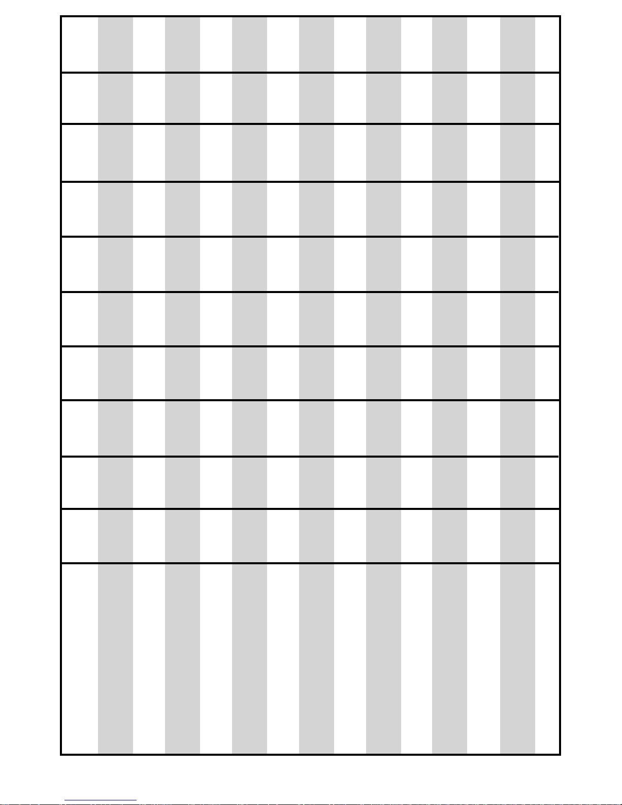
" 1" Insulation Blanket, Left Inner/Middle 1050080 1050080 1050080 1050080 1050080 1050080 1050080 1050080 1050080 1050080
" 1" Insulation Blanket, Left Outer 1050009 1050009 1050009 1050009 1050009 1050009 1050009 1050009 1050009 1050009
38 T-Block Mounting Bracket (Aux.) N/A N/A N/A N/A N/A N/A N/A N/A 1141084 1141084
39 Bimetallic Coil Assembly 1190015 1190015 1190015 1190015 1190015 1190015 1190015 1190015 1190015 1190015
40 Umbilical Cord 1040003 1040260 1040003 1040261 1040002 1040261 1040008 1040263 1040041 1040263
41 1" Insulation Blanket, Right Inner/Middle 1050072 1050080 1050072 1050080 1050072 1050080 1050072 1050080 1050072 1050080
42 1" Insulation Blanket, Right Outer 1050008 1050009 1050008 1050009 1050008 1050009 1050008 1050009 1050008 1050009
" Block Insulation, Left (Std Output) 1052022 1052022 1052022 1052022 1052022 1052022 1052022 1052022 1052022 1052022
43 Block Insulation, Right (Std Output) 1052035 1052040 1052035 1052040 1052035 1052040 1052035 1052040 1052035 1052040
44 Charge Control Knob 1154008 N/A 1154008 N/A 1154008 N/A 1154008 N/A 1154008 N/A
45 Charge Control Thermostat 1040286 N/A 1040286 N/A 1040286 N/A 1040286 N/A 1040286 N/A
46 Grill 1140022 1142080 1140024 1142081 1140026 1142082 1140028 1142083 1140030 1142084
*47 Fan Assembly w/o Fan (Std Output) 1040092 1040092 1040093 1040093 1040094 1040094 1040095 1040095 1040109 1040109
49 Charge Control Sequencer N/A N/A N/A N/A 1040000 1040000 1040000 1040000 1040000 1040000
*48 Fan Wiring Harness (Std Output) 1040065 1040290 1040066 1040291 1040067 1040292 1040068 1040293 1040069 1040294
*50 Red Service Light (240VAC) 1015020 1015021 1015020 1015021 1015020 1015021 1015020 1015021 1015020 1015021
51 Painted Panel, Right 1141141 1142040 1141141 1142040 1141141 1142040 1141141 1142040 1141141 1142040
52 Painted Panel, Left 1141140 1141140 1141140 1141140 1141140 1141140 1141140 1141140 1141140 1141140
*53 Fan with Motor & Shroud (230 VAC) 1022000 1022000 1022007 1022007 1022004 1022004 1022004 1022004 1022007 1022007
55 Sequencer Mounting Bracket N/A N/A N/A N/A 1141082 1141082 1141082 1141082 1141082 1141082
56 Fan High Limit Switch 1012013 1012013 1012013 1012013 1012013 1012013 1012013 1012013 1012013 1012013
*54 Heating Element (1200W, 240 VAC) 1040079 1040079 1040079 1040079 1040079 1040079 1040079 1040079 1040079 1040079
57 T-Block Mounting Bracket, Center N/A N/A N/A N/A N/A N/A 1141083 1141083 N/A N/A
58 Wall Bracket Hardware Kit 1190002 1190002 1190002 1190002 1190002 1190002 1190002 1190002 1190002 1190002
) N/A 1040282 N/A 1040282 N/A 1040282 N/A 1040282 N/A 1040282
o
59 Green Charge Light, Optional 1015026 1015026 1015026 1015026 1015026 1015026 1015026 1015026 1015026 1015026
60 Right Panel, Front N/A 1142047 N/A 1142047 N/A 1142047 N/A 1142047 N/A 1142047
61 Charge Control Assy (130
) N/A 1040280 N/A 1040280 N/A 1040280 N/A 1040280 N/A 1040280
) N/A 1040284 N/A 1040284 N/A 1040284 N/A 1040284 N/A 1040284
o
o
62 Charge Control Assy (285
63 Charge Control Assy (190
64 Cord Assembly (120 VAC) N/A 1015000 N/A 1015000 N/A N/A N/A N/A N/A N/A
65 Room Temp. Control Knob N/A 1154006 N/A 1154006 N/A 1154006 N/A 1154006 N/A 1154006
66 Tip Over Switch (120V plug-in units) N/A 1024018 N/A 1024018 N/A N/A N/A N/A N/A N/A
67 Outdoor Temperature Sensor, optional N/A 1040300 N/A 1040300 N/A 1040300 N/A 1040300 N/A 1040300
68 Circuit Board Mounting Plate N/A 1142087 N/A 1142087 N/A 1142087 N/A 1142087 N/A 1142087
70 Low Voltage Wire Channel N/A 1142090 N/A 1142090 N/A 1142090 N/A 1142090 N/A 1142090
*69 Circuit Board Face Plate N/A * N/A * N/A * N/A * N/A *
71 Outdoor Sensor Interface Board, optional N/A 1043020 N/A 1043020 N/A 1043020 N/A 1043020 N/A 1043020
72 Security Base Shell (120V plug-in units) N/A 1142110 N/A 1142112 N/A N/A N/A N/A N/A N/A
73 Security Base Filler (120V plug-in units) N/A 1190020 N/A 1190022 N/.A N/A N/A N/A N/A N/A
75 Peak Control Sequencer, optional N/A 1309006 N/A 1309006 N/A 1309006 N/A 1309006 N/A 1309006
76 Utility Mode Timer, optional N/A 1018015 N/A 1018015 N/A 1018015 N/A 1018015 N/A 1018015
*74 Time Clock (240 VAC), optional N/A 1301006 N/A 1301006 N/A 1301006 N/A 1301006 N/A 1301006
77 Peak Override Wind-up Timer, optional N/A 1024020 N/A 1024020 N/A 1024020 N/A 1024020 N/A 1024020
78 Multi-Mode Interface Board, optional N/A 1023030 N/A 1023030 N/A 1023030 N/A 1023030 N/A 1023030
circuit board configurations are available.
* Contact factory with model and serial number as optional voltages, wattages, high output fan assemblies and
Page 24
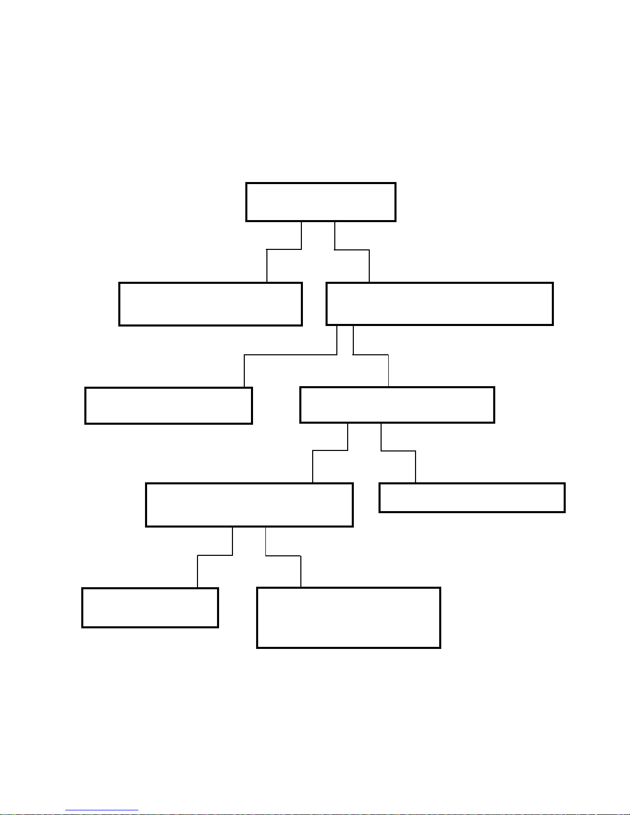
F. ROOM UNIT TROUBLESHOOTING GUIDES
Model: S Series Only
Function: Air Delivery
Problem: Fan(s) do not operate.
Before starting any procedures listed below, check room thermostat and circuit breaker settings.
Note: For cross reference to number coded components, see figure 7.
Set wall thermostat to high
stop position.
FAN(S) NOW OPERATE.
Check wall thermostat for
possible miscalibration
FAN(S) DO NOT OPERATE.
Check voltage across F1 & F2 terminal
block positions (24).
NO VOLTAGE PRESENT VOLTAGE PRESENT
Check wall thermostat and/or
field wiring.
Check voltage across fan high limit
switch terminals (56).
NO VOLTAGE PRESENT VOLTAGE PRESENT
Remove fan assembly (47) and check
Replace fan limit switch (56).
voltage to fan motor(s) (53).
NO VOLTAGE PRESENT
Check units internal
wiring.
VOLTAGE PRESENT
Check fan impeller for debris that
could cause jamming. Replace if
necessary.
Page 25
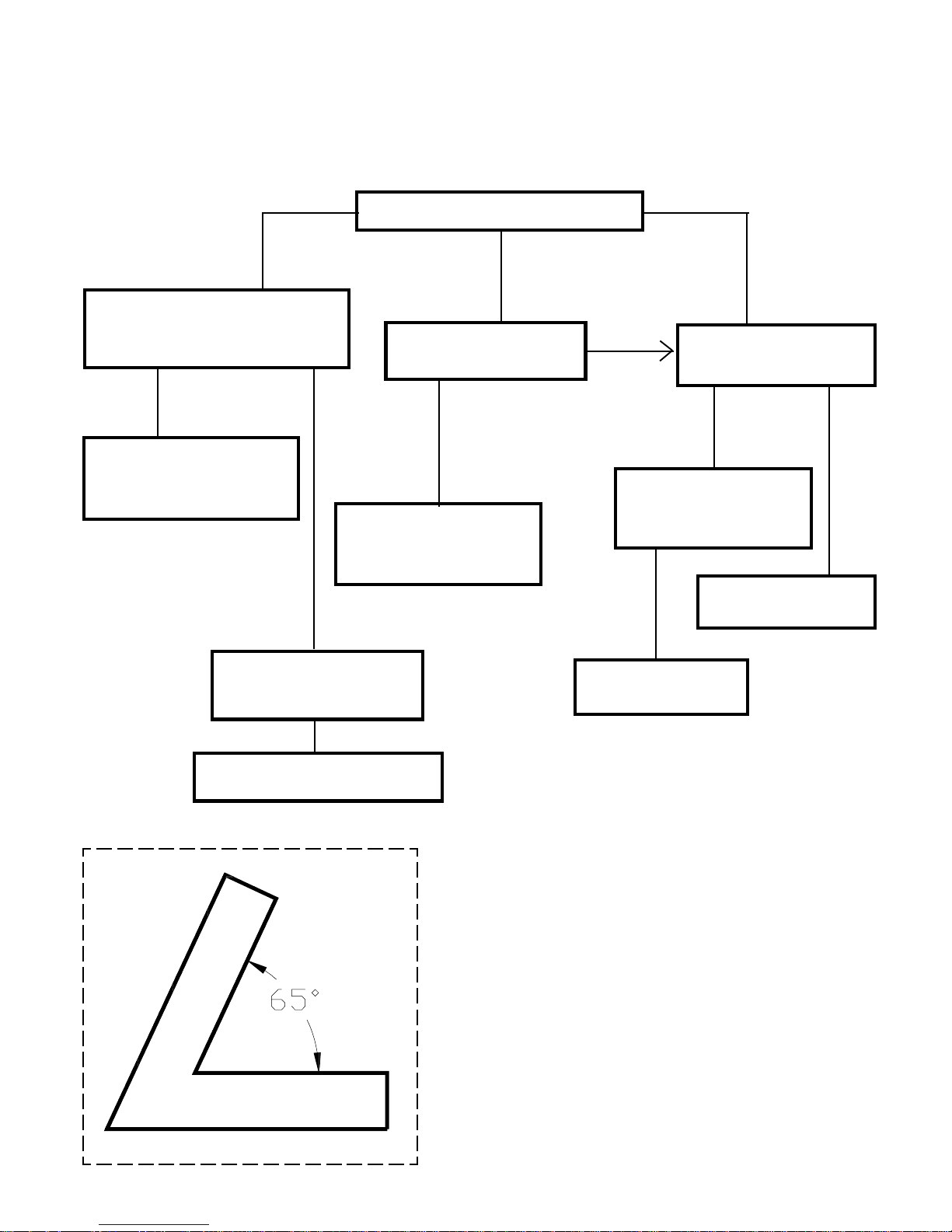
Before starting any procedures listed below, check room thermostat and circuit breaker settings.
Note: For cross reference to number coded components, see figure 7.
FANS RUN
INTERMITTENTLY
Check for damper jamming and
bimetallic coil assembly (39)
calibration.
PROBLEM
PRESENT
Recalibrate bimetallic coil
assembly (39), or repair or
replace fan assembly (47).
OK
Model: S Series Only
Function: Air Delivery
Problem: Improper Air Discharge.
Unit discharges improperly.
DISCHARGE AIR
TOO COOL
Check for adequate
core temperature
PROBLEM WITH
CORE CHARGING
See Core Charging, Unit
Will Not Charge, flow
chart to troubleshoot.
DISCHARGE
AIR
TOO WARM
OK
Check for damper
jamming or obstruction.
OK
PROBLEM
PRESENT
Check bimetallic coil
assembly (39) for proper
calibration (see note).
Repair or replace fan
assembly (47).
Install damper clearancing
bracket, Steffes ETS item
#1140209
If problem persists, replace fan
high limit switch (56).
Check unit for proper
amperage draw.
NOTE: To test the bimetallic coil assembly, it must
be completely cold. Either allow room unit to cool
completely or remove fan assembly and cool to
room temperature. Once the coil is cold, disconnect
the damper linkage and let the bimetallic coil go to
its relaxed position. The bimetallic coil on units
equipped with air deflectors should be calibrated at
a 90o angle from the front of the fan assembly. The
bimetallic coil of units not equipped with an air
deflector are calibrated at a 65o angle from the front
of the fan assembly. Use the cutout gauge on the left
for checking this calibration. (To determine whether
the unit is equipped with an air deflector, these
deflectors would be located in fan assembly behind
bimetallic coil.)
Page 26
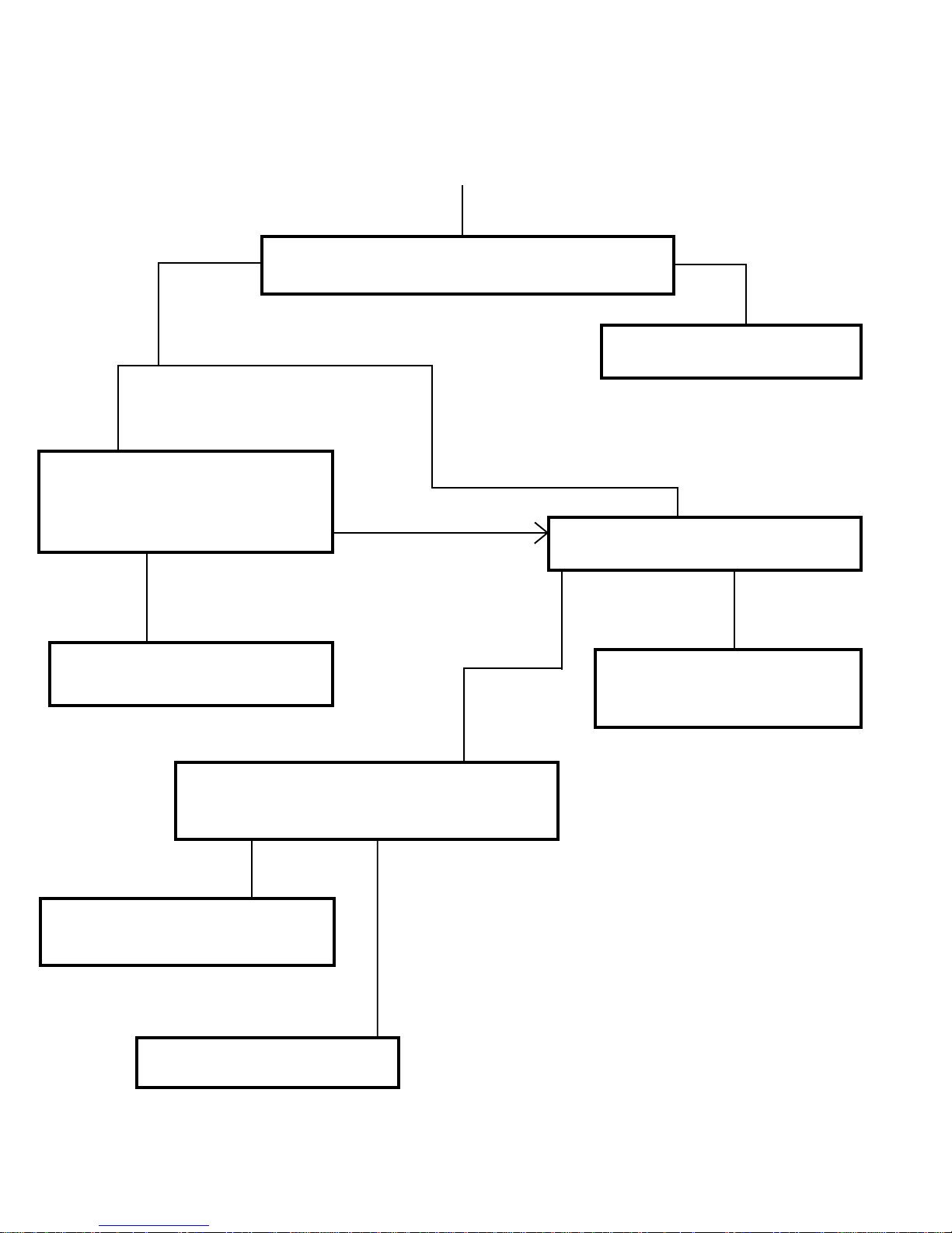
Model: S Series Only
Function: Core Charging
Problem: Unit will not charge.
Before starting any procedures listed below, check room thermostat and circuit breaker settings.
Note: For cross reference to number coded components, see figure 7.
VOLTAGE
PRESENT
With charge control thermostat (45)
in highest position, check for line
voltage between A1 and A2 terminal
block positions (24).
VOLTAGE PRESENT
Troubleshoot and repair load
management control or field wiring.
Check for line voltage between L1 and L2
terminal block positions (24).
CHARGE
CONTROL
CIRCUIT
UNUSED
NO VOLTAGE PRESENT
Check for voltage between L1 and T1
terminal block positions (24).
NO VOLTAGE
PRESENT
Recheck charge control thermo-
NO
VOLTAGE
PRESENT
Troubleshoot and repair field
wiring.
VOLTAGE
PRESENT
stat (45) setting and/or replace
thermostat.
Check for line voltage between L2 and T2
terminal block positions (24), or observe
service light for illumination (50).
VOLTAGE PRESENT
(Service light on.)
Replace core charging high limit
switch (33).
NO VOLTAGE PRESENT
(Service light off.)
Check unit wiring and heating
elements (54).
Page 27
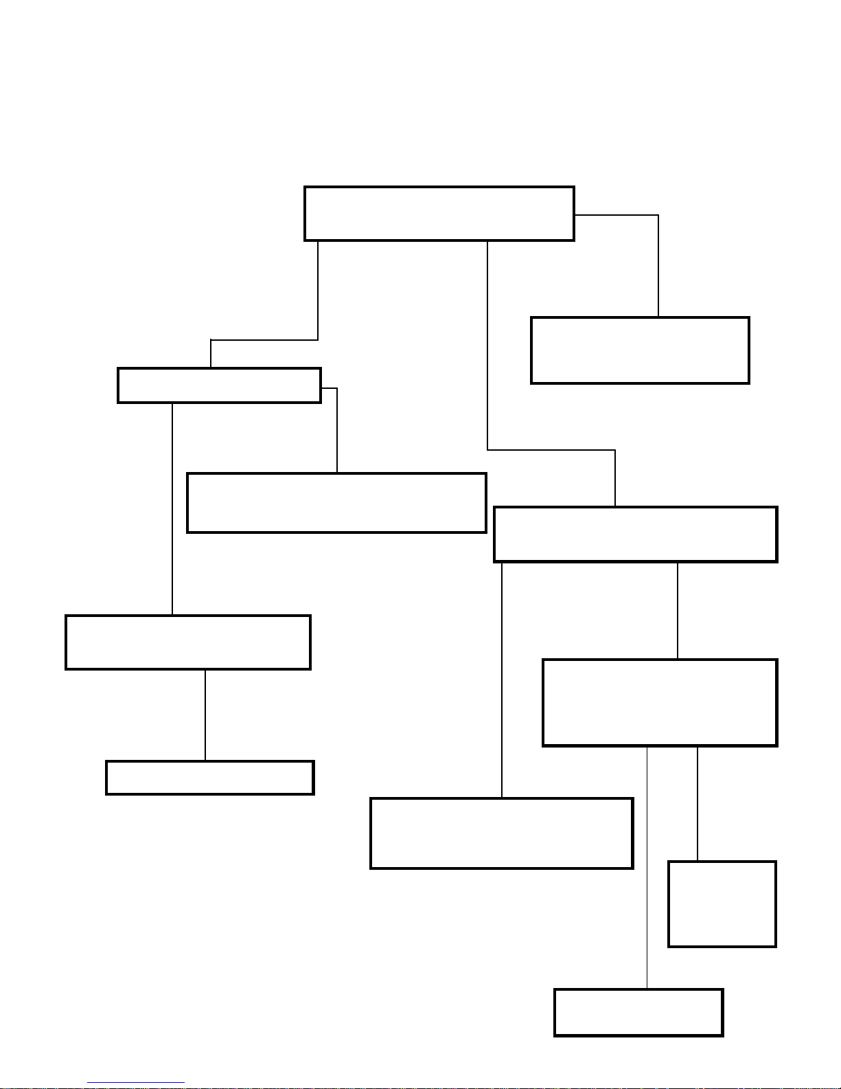
Model: S Series Only
Function: Core Charging
Problem: Improper Charging
Before starting any procedures listed below, check room thermostat and circuit breaker settings.
Note: For cross reference to number coded components, see figure 7.
Unit charges improperly.
UNIT
OVERCHARGES
UNIT
CHARGES
UNIT
UNDERCHARGES
(With manual
Charge Control.)
UNEVENLY
Check unit wiring. If correct,
replace charge control
thermostat (45).
Check unit amperage.
LESS THAN
RATED
OK
AMPERAGE
Check heating elements (54) and charge
control sequencer (49) for proper operation.
RATED
AMPERAGE
Check fans (53) and dampers for
smooth operation.
DEFECTIVE
Repair fan/damper system.
Check voltage between A1 and A2
terminal block positions (24).
VOLTAGE
PRESENT
Check for line voltage between L2
and T2 terminal block positions
(24), or observe service light for
Troubleshoot and repair load management control, automatic charge
control system or field wiring.
VOLTAGE
PRESENT
(Service light off.)
illumination.
NO
NO
VOLTAGE
PRESENT
VOLTAGE
PRESENT
(Service
light on.)
Replace core
charging high
limit switch
(33).
Replace charge
control thermostat (45).
Page 28
WARRANTY
Steffes Corporation (“Steffes”) warrants that the Steffes ETS Electric Thermal Storage Heating
Appliance is free from defects in materials and workmanship under normal use and service. Steffes’
obligation under this Warranty is limited to the repair or replacement of the appliance or parts which
prove to be defective under normal use within five (5) years of the date of installation and which
Steffes’ examination of the returned appliance or part(s) shall verify to Steffes’ satisfaction that it
is defective.
This Warranty is void if the heating appliance is moved from the premises in which it was
originally installed. This Warranty shall not apply to an appliance or part which has been altered
in any respect, or improperly installed, serviced or used, or has been subject to accident, negligence,
abuse or misuse.
THE ABOVE WARRANTY BY STEFFES IS EXCLUSIVE AND IN LIEU OF ALL
OTHER WARRANTIES, WHETHER WRITTEN OR ORAL, EXPRESS OR IMPLIED,
INCLUDING ANY IMPLIED WARRANTY OF MERCHANTABILITY OR OF FITNESS
FOR A PARTICULAR PURPOSE.
The buyer assumes all risk and liability whatsoever resulting from the use of this heating
appliance. In no event shall Steffes be liable to purchaser for any indirect, special or consequential
damages or lost profits.
This Limited Warranty contains the complete and exclusive statement of Steffes’ obligations
with respect to the heating appliance and any parts thereof. The provisions hereof may not be
modified in any respect except in writing signed by a duly authorized officer of Steffes.
The equipment described herein is intended for installation in accordance with applicable local, state and national electrical codes
and must be installed by a qualified electrician.
This manual should be retained by owner upon completion of the
installation and made available to service personnel as required.
3050 Highway 22 North
Dickinson, ND 58601-9413
"Commitment to Innovation"
ITEM NO. 1200050
 Loading...