

Page 1
"Manufactured in North America"
OWNER'S AND
INSTALLER'S MANUAL
for
V10
Room Heating Units
Models: 2002, 2003, 2004, 2005, & 2006
LI STED
Page 2

Table of Contents
1
Introduction .................................................................................................................................................................2
General Information
General Operation ..........................................................................................................................................................................3
Terminology ................................................................................................................................................................................... 4
Safety Information
Safety Precautions .......................................................................................................................................................................... 5
Built-in Safety Devices ................................................................................................................................................................... 5
Maintenance and Cleaning ......................................................................................................................6
Describing the Heater's Display Panel ................................................................................. 6-7
Operating the Heater
Heater Start-up ............................................................................................................................................................................... 8
Adjusting the Room Temperature Set Point .................................................................................................................................. 8
Adjusting the Brick Core Charge Level ..................................................................................................................................... 8-9
How to Turn the Heater "OFF" and "ON" .....................................................................................................................................9
Installing the Heater
Placement .....................................................................................................................................................................................10
Clearance Requirements............................................................................................................................................................... 10
Electrical Connections............................................................................................................................................................ 10-11
Attaching the Wall Mount Bracket or Security Base ...................................................................................................................12
Brick Loading............................................................................................................................................................................... 13
Setting the Method of Brick Core Charge Control ................................................................................................................ 13-14
Remote Room Sensor (Optional)..................................................................................................................................................14
Installer's Instructions for Setting Heater Operation Functions................................................................................................... 14
Installer's Final Checkout Procedure ...................................................................................................................................... 15-16
Heater Wiring
Room Heating Unit Identification Label ...................................................................................................................................... 17
Room Heating Unit Umbilical Cord (Wiring Harness) Color Code ...........................................................................................17
Field Connection Wire and Circuit Breaker Sizing Guide ..........................................................................................................17
Typical System Wiring Diagram..................................................................................................................................................18
Heater Dip Switch Settings ..........................................................................................................................................................19
Typical Low Voltage Control Wiring Diagrams..........................................................................................................................20
Room Heating Unit Line Voltage Wiring Diagrams ............................................................................................................. 21-22
Room Heating Unit Specifications ..............................................................................................23
Exploded View Heater Diagram ......................................................................................................24
Heater Parts List ..................................................................................................................................................25
Advanced Heater Operation
How to Change the Heater's Operation ........................................................................................................................................ 26
Temperature Conversion Chart ....................................................................................................................................................27
Describing the Heater Functions (L00 through L10)............................................................................................................. 27-30
Brick Core Operating Modes: "C", "P", and "A" ................................................................................................................... 30-32
Customer Notes ..................................................................................................................................................... 33
Warranty
Five (5) Year Warranty Policy ..................................................................................................................................................... 34
Page 3

2
Dear Valued Customer:
Congratulations on your new purchase! The Steffes ETS heaters are the highest quality storage heat systems available
today. We are confident you will be pleased with the warm, comfortable heat this system provides as well as the
savings you should see in your electric heat bill.
Electric Thermal Storage has been used in the United States for over 20 years. Today, Steffes is known as the leader
in this technology. Not only are we setting the industry standards for quality; but, we are also working closely with
power companies to ensure comfort, safety, reliability, service, and support needs are being met.
We are committed to ensuring your new heating system will provide you with total satisfaction for many years to
come. Your support is appreciated and your comments on the equipment are welcome.
Thank you for choosing Steffes ETS!
Sincerely,
Paul Steffes
President and Chief Executive Officer
Introduction
• This manual provides information for the correct installation procedures and electrical connections for Steffes
ETS room heating units, Models: 2002, 2003, 2004, 2005 and 2006. The information in this manual can help
you take full advantage of the many features built-in to your heater and ensure years of safe, reliable operation.
Read the enclosed instructions, safety tips, and warranty information. Store this manual in a safe place for future
reference.
• Assembly of and/or service to these units should be performed only by a qualified electrician in accordance with
information contained herein and in accordance with national, state, and local electrical codes.
• This manual should be retained by new owners if ownership of the heater changes.
• Any deviation from these instructions may void the warranty and could result in hazardous operating conditions.
• A Supplemental Installer's Guide is available from the factory or distributor (with power company consent) and
should only be made available to installing electrical contractors or to power company personnel. This guide
describes those heater functions that are related to power company control and how to change them. It is not
required to complete an installation.
• The warranty registration card provided as part of the documentation included with the heater must be completed
and returned to Steffes Corporation. Failure to do so may adversely affect warranty claims.
• Record the Serial Number and Model Number in the space provided in the Installation Information Section of this
Owner's Manual. These numbers are located on the lower left side panel of the heater, on the shipping box, and
on the Warranty Registration Card. Retain this manual for quick future reference to these numbers.
• Disclaimer: In compiling this manual, Steffes Corporation has used its best judgement based upon information
available, but disclaims any responsibility or liability for any errors or miscalculations contained herein, or any
revisions hereof, or which result, in whole or in part, from the use of this manual or any revisions hereof.
Page 4

General Information
1
General Operation
Steffes ETS room heating units utilize off-peak electricity available during those times of the day or
night when the power company can supply you with electricity more economically. By using this offpeak electricity for heating, the power company may offer you a special incentive such as a reduced
electric rate, an off-peak heating rate, a time-of-use (TOU) rate, or monthly credits on your heating bill.
When off-peak hours are available, the room heating unit converts electricity to heat which is then
stored in its ceramic brick core. The ceramic brick core of the heater can store heat at varying levels
depending upon outdoor temperature, owner preference, utility peak conditions, and the requirements of
the space being heated. This stored heat becomes available for space heating needs as determined by
the room temperature sensor located in the heater. (An optional remote room temperature sensor is also
available. Order item #1302024.)
Heating is accomplished radiantly and by a thermostatically controlled blower. A small amount of heat
will be radiated by the heater's cabinet. However, most of the heating requirements in the area where
the heater is installed will be satisfied by the heater's blower. When the room thermostat senses a need
for heat, the heater's blower will circulate room air through the heater's ceramic brick core. This air is
heated and discharged back into the room to maintain a constant, comfortable room temperature.
3
Page 5
4
2
Terminology
This manual contains terms which may need an explanation. The table below lists some of these terms and a brief
description of each.
TERM DEFINITION
Automatic Charge Control Method of brick core charge regulation where a sensor monitors outdoor temperature to
Brick Core Charge Level The amount of heat that is stored in the heater's brick core.
Charge Period Off-peak time in which the heater is allowed to store heat in its brick core.
Control Panel Contains the buttons to adjust and the display to indicate heater functions. Located on
Control Period On-peak time in which the heater is not allowed to store heat in its brick core.
Data The specific information for heater operation which is set and stored in a location on the
Edit Mode Process of changing or viewing the data in a microprocessor location. This is accom-
General Information (cont'd)
automatically adjust the brick core temperature.
the front of the heater in the upper right corner.
heater's microprocessor. This data is accessed through the control panel. Displayed as a
"d" on the control panel when in the edit mode.
plished with the use of the M (mode) button, the (up arrow) button, and the
(down arrow) button.
Location (Function) Where the specific operating information (data) of the heater is stored. These locations
are part of the heater's microprocessor and are accessed through the control panel.
Displayed as an "L" on the control panel when in the edit mode.
Manual Charge Control Method of brick core charge regulation where the owner must periodically adjust the
brick core temperature setting in relation to the outdoor temperature.
Microprocessor Device on the circuit board of the heater which stores and processes the data informa-
tion and controls the operation of the heater.
Off-peak The time during the day or night when the power company can supply electricity more
economically and may offer a special incentive such as a reduced electric rate or billing
credits for the electricity consumed during this time. Typically, electrical usage is not
controlled during an off-peak time. (The heater will provide heat to satisfy comfort
requirements during this time as well as charge or store heat in its brick core.)
On-peak The time during the day or night when the power company experiences a high demand for
electricity. To limit demand, certain appliances are controlled to avoid usage by them
and/or a premium for the electricity consumed during this time may be charged to
discourage electrical usage. (The heater is not allowed to charge or store heat in its brick
core during peak periods. Heating requirements are satisfied by only the heat it has
stored in its brick core.)
Outdoor Sensor Device that senses outdoor air temperatures and communicates this information to the
heater for automatic charge control.
Room Temperature Set The targeted room temperature at which the heater is to maintain. If the room thermo-
Point (Room Setting)
Storage Level Set Point The targeted amount of heat that is to be stored in the brick core of the heater. If the
(Storage Setting)
stat senses a temperature below this point, the heater's blowers will come on and extract
heat from the brick core.
brick core temperature is below this set point, the heating elements will come on (only if
off-peak) and add heat to the brick core.
Page 6
Safety Information
1
Safety Precautions
1. DO NOT energize the heater while disassembled or without ceramic heat storage bricks in place.
2. As is true with all heating appliances, materials that may produce explosive or flammable gases MUST NOT be used or
stored near the room heating unit.
3. Be sure the minimum clearance requirements specified in this manual are never violated .
WARNING: Violation of the clearance requirements may create a fire hazard!
4. DO NOT allow objects to fall between the room heating unit and the wall.
5. DO NOT place anything on top of the room heating unit.
6. DO NOT stick any objects through the air discharge grill.
7. This heater may be connected to more than one branch circuit. Disconnect power to all circuits before servicing.
8. Installation of and/or service to this heater should be performed by a qualified electrician in accordance with information contained herein and with national, state, and local electrical codes.
9. This manual must remain with the room heating unit.
5
Built-in Safety Devices
2
DEVICE NAME FUNCTION
Core Charging High These limit switches run across the entire back of the heater and
Limit Switches monitor the temperature of the outside back panel and the
heater's brick core. If the normal operating temperature is
exceeded, this switch will interrupt power to the heating elements
and prevent heat from being stored in the brick core. The red
"SERVICE" light will illuminate to indicate this switch has shut
the power off to the heating elements. (This switch will automatically reset when the temperature returns to a normal range.)
Red "SERVICE" Light Illuminates when the core charging high limit switch has
interrupted power to the heating elements. The heater will not
store heat in the brick core when this light is illuminated.
Illumination of the light may indicate there is not enough
clearance between the heater and some object; or, possibly, there
is an operational difficulty within the heater. If the clearance
requirements have been maintained and the light illuminates
repeatedly, notify a service technician. (Since this light works in
conjunction with the core charging high limit switch, it will
automatically turn off when this switch resets.)
LOCATION
ON HEATER
Inside the
Back Panel
On the
Control Panel
Discharge Air High Monitor discharge air temperature and interrupt power to the
Limit Switches blower if the normal operating temperature is exceeded. This
limit switch helps protect against the heating of objects which
may obstruct the air discharge area.
Tip Over Switch Interrupts power to the heating elements and the blower to
(Heaters equipped with a
security base only.)
prevent the heater from storing heat in or discharging heat from
the brick core if the heater is not in the upright position.
Inside the
Air Discharge Grill
Inside the Electrical
Compartment
Page 7
6
As with most heating systems, air borne particles in the room may be drawn into the heating system and oxidized. As
these air borne particles are expelled back into the room, they may accumulate on the heater or other surfaces. Over
time, these particles may appear as a black residue, commonly referred to as soot. High concentrations of air borne
particles from such things as aerosols, dust, candles, incense, pet hair, high humidity, smoke, or cooking can contribute to poor indoor air quality and accelerate this process.
To minimize the black residue buildup, clean the outer surface of the heater on a regular basis. Wash the cabinet only
when cool with any liquid cleaner. Do not use scouring powders or furniture polish. Steffes recommends using "Soft
Scrub with Bleach" brand cleanser or its equal.
Regularly vacuum around all sides of the heater. Check the back of the heater to make sure no objects have fallen
behind it. Check all sides of the heater to be sure the required clearances are not being violated. Objects should never
be placed on top of the heater. No additional routine maintenance is required.
Maintenance and Cleaning
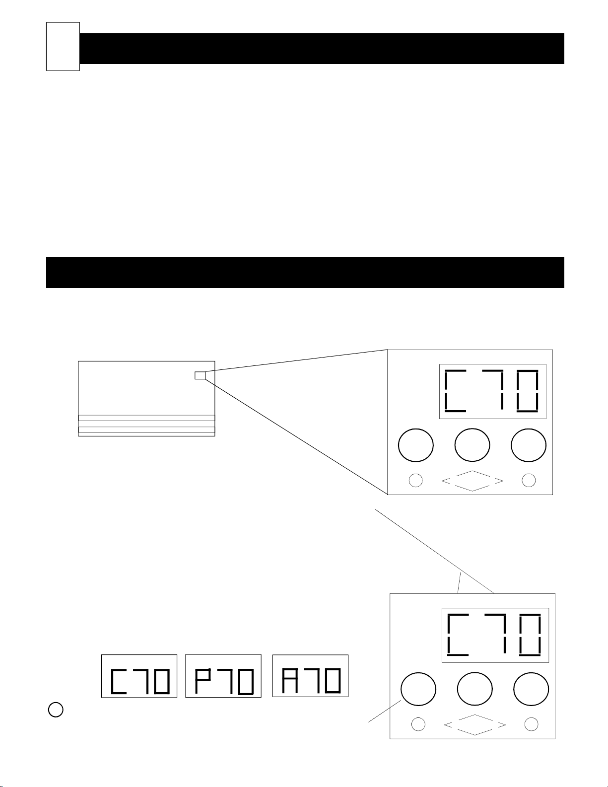
Describing The Heater's Display Panel
All operational functions of the heater are stored in the heater's microprocessor. These operational functions are
factory preset; however, they can be adjusted by the user or installer. All operational functions are accessed
through the heater's control panel. Typically, the user will only need to use this panel to adjust the room temperature; and, possibly, to set the brick core temperature if manual charge control is used.
TEMPERATURE and MODE Digits
Typically, these digits continuously display current room temperature and
one of the following brick core operating modes (Refer to the Advanced
Heater Operation section of this manual for more information):
C = (charge period) Off-peak time in which the heater is allowed
to store heat in its brick core. (See Figure 2)
P = (peak period) On-peak time in which the heater is not
allowed to store heat in its brick core. (See Figure 3)
A = (anticipated peak period) Used only in certain utility pro-
grams. It is an alternative method of storing heat in the
heater's brick core. (See Figure 4)
Figure 2
MODE TEMPERATURE
Figure 3
MODE TEMPERATURE
Figure 4
MODE TEMPERATURE
ROOM
SETTING
SERVICE
STORAGE
SETTING
MODE
M
STEFFES
Figure 1
Heater Control Panel
ROOM
SETTING
SERVICE
STORAGE
SETTING
MODE
TEMPERATURE
TEMPERATURE
M
Mode (EDIT) Button
Activates the editing process for changing the operating information of
the heater. PLEASE USE CAUTION WHEN EDITING THE IN-
FORMATION IN THE HEATER.
M
STEFFES
Page 8
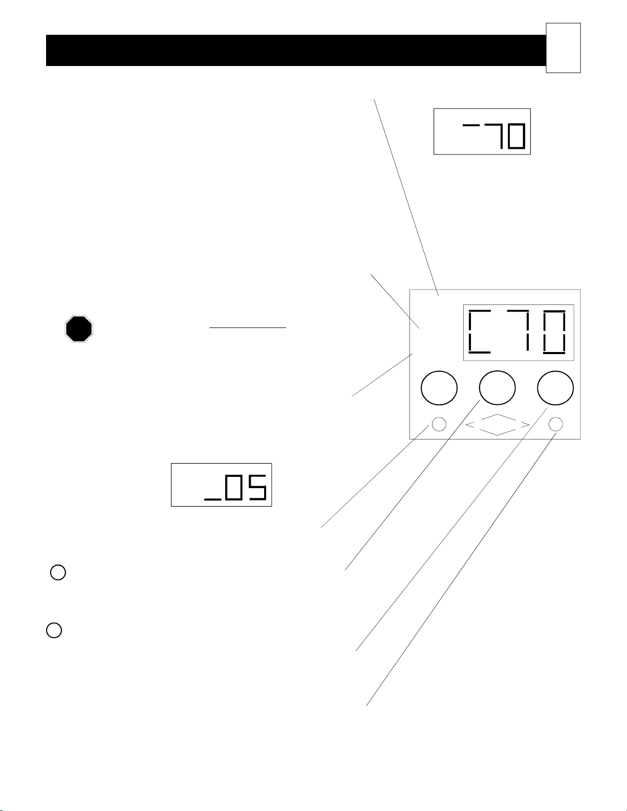
Describing The Heater's Display Panel (cont'd)
NOTE
ROOM SETTING
A green bar will illuminate next to ROOM SETTING on the MODE
digit when the room temperature set point is being adjusted. (See
Figure 5.) The set point can range from 45oF (7.2oC) through 85oF
(29.4oC).
SERVICE LIGHT
This is one of the many built-in safety devices on the heater. This
red light will illuminate whenever the core charging high limit switch
has interrupted power to the heating elements. This interruption may
be the result of not enough clearance between the heater and some
object; or, possibly, there is an operational difficulty within the
heater. If this light is illuminated, the heater will not store heat in
the brick core. It will automatically reset (turn off) when the core
charging high limit switch restores power to the elements. (Refer to
Table 1, Built-in Heater Safety Devices, for more information on the
light and the core charging high limit switch.)
If the light illuminates REPEATEDLY, notify a service
technician.
STORAGE SETTING
This is only applicable when using manual charge control. A green
bar will illuminate next to STORAGE SETTING (on the MODE
digit) which indicates the storage level set point can be adjusted.
(See Figure 6.)
ROOM
SETTING
SERVICE
STORAGE
SETTING
Figure 5
MODE TEMPERATURE
ROOM
SETTING
MODE
STEFFES
TEMPERATURE
M
7
Figure 6
MODE TEMPERATURE
STORAGE
SETTING
Left Indicator Light
Illuminates green whenever the heating elements are on.
Up Arrow Button
Increases room temperature set point. It is also used to scroll
upward when viewing or adjusting the heater's operational functions.
Down Arrow Button
Decreases room temperature set point. It is also used to scroll
downward when viewing or changing the heater's operational functions.
Right Indicator Light
Illuminates green continuously if automatic brick core charge regulation is being utilized.
Page 9
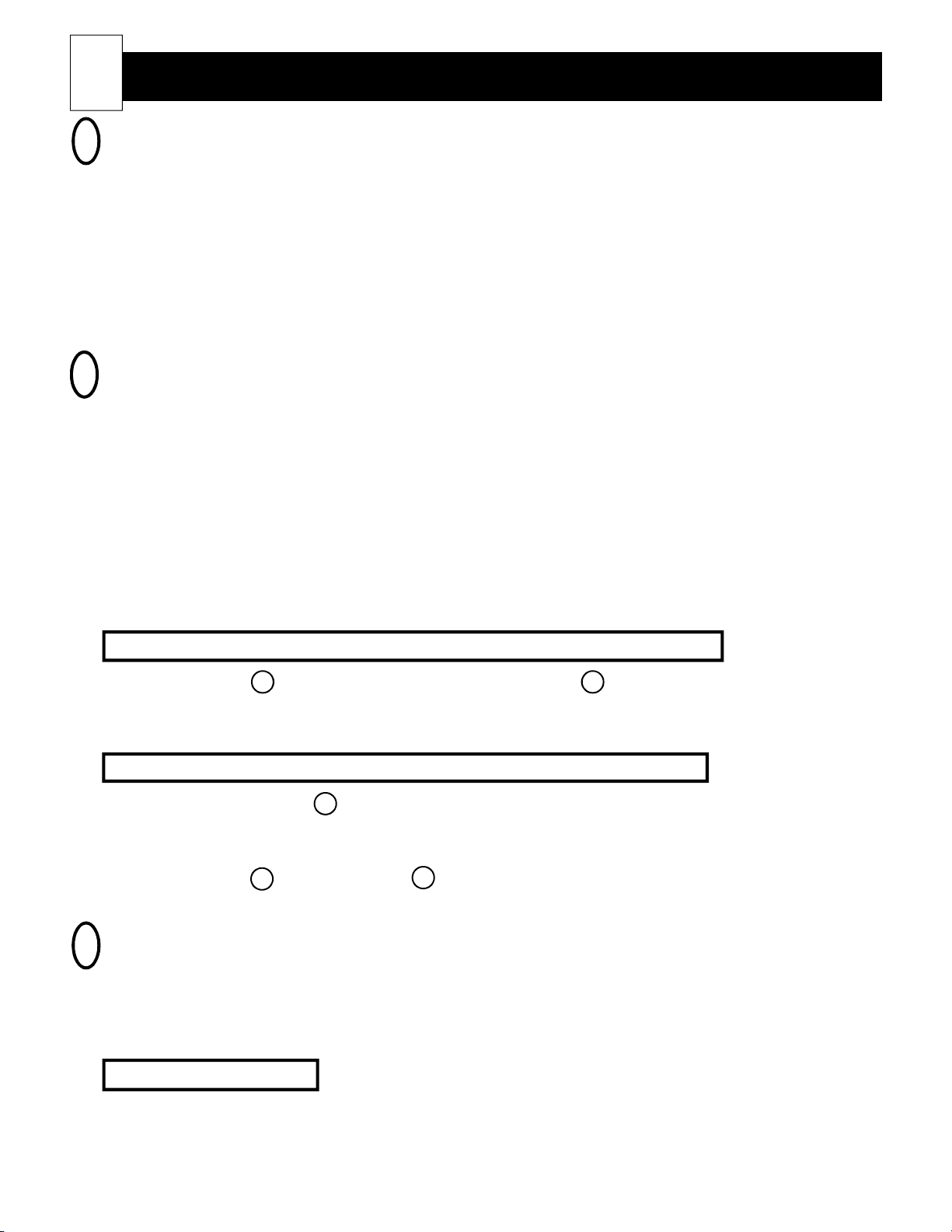
8
HEATER START-UP
1
On start-up of the heater, you may experience some odors relating to the first time operation of the heating
components. There also may be an odor associated with dust accumulation in the system if the heater is shut
down for an extended period of time. Allowing the heater to charge to its highest heat storage level (full core
charge) will help expel these odors in a timely manner.
Since room air passes directly through the hot brick core of the heater, air borne particles and odors may be
drawn into the heating system and oxidized. During the oxidation process, odors can be amplified; thus, it is
recommended not to operate the heating system if odors such as that from paints, varnishes, or chemicals are
present in the air. Allow the area to be completely aired out before operating the heater.
ADJUSTING THE ROOM TEMPERATURE SET POINT
2
Room temperature set point is adjusted differently if using manual charge control versus automatic charge
control. Thus, when making adjustments to the room temperature set point or the brick core charge level, you
must determine whether your heating system is set for automatic or manual charge control.
Automatic charge control - The right indicator light on the control panel will be illuminated. With automatic
Operating the Heater
charge control, a sensor regulates the amount of heat stored in the heater's brick
core automatically in relation to outdoor temperature.
Manual charge control - The right indicator light will not be illuminated. With manual charge control, the
user regulates the amount of heat stored in the heater's brick core in relation to
outdoor temperature.
How to Adjust Room Temperature Set Point if Using Automatic Charge Control
Step 1 Press the arrow button to increase the set point or the arrow button to decrease the set point.
The face plate will automatically return to displaying current room temperature a few seconds after
making an adjustment.
How to Adjust Room Temperature Set Point if Using Manual Charge Control
Step 1 Press and hold the M button until a green bar appears on the MODE digit of the control panel face
plate to indicate room setting can be adjusted. The room temperature set point will appear on the
TEMPERATURE digits of the face plate.
Step 2 Press the arrow button or the arrow button to adjust the room temperature set point. The face
plate will automatically return to displaying current room temperature after making an adjustment.
ADJUSTING THE BRICK CORE CHARGE LEVEL
3
The room heating unit's brick core charge level can be regulated either manually or automatically. The method of
control will be set at the time of installation. If the right indicator light is illuminated on the face plate, the
heater is set for automatic charge control. If it is not illuminated, the heater is set for manual charge control. The
room heating unit will come factory preset for automatic charge control.
Automatic Charge Control
If the room heating unit is set for automatic charge control, the brick core charge level will be regulated automatically in relation to outdoor temperature. An outdoor sensor is required for this method of charge control.
Page 10
Operating the Heater (cont'd)
The outdoor sensor will monitor outdoor temperature and provide the information to the heater. The heater will
respond by storing heat in the brick core accordingly. The outdoor temperature at which brick core charging in
the heater is to begin and the outdoor temperature the heater should be at full brick core charge may be adjusted
at the time of installation. The heater comes factory preset to start charging at 60oF (15.6oC) and to be at full
brick core charge at 20oF (-6.67oC).
Manual Charge Control
If manual charge control is being used, the owner must periodically adjust the brick core charge level setting
during the heating season in relation to outdoor temperature and the heating requirements of the area. To adjust
the brick core charge level, do the following:
Step 1 Press and hold the M button until a green bar appears on the MODE digit of the control panel face
plate next to room setting. Release the button.
Step 2 Press the M button again. The green bar on the MODE digit of the control panel face plate will
move to indicate storage setting can be adjusted. Core charge level set point is displayed on the
TEMPERATURE digits.
Step 3 Press the or arrow buttons to adjust the core charge level set point. The core charge level can
be set to any data value from 00 through 10.
9
00 = no core charging will occur
05 = 50% core charge will be maintained
10 = maximum core charge will be maintained
The face plate will automatically return to displaying current room temperature a few seconds after
making an adjustement.
HOW TO TURN THE HEATER "OFF" AND "ON"
4
You may wish to turn the heater off during the summer months. Brick core charging and room temperature
sensing can be turned off without disconnecting power to the heater.
Using Automatic Charge Control
Step 1 To turn the heater "OFF", use the arrow button to decrease the room temperature set point until
the control panel face plate displays "OFF".
Step 2 To turn the heater back "ON", press the arrow button to adjust room temperature to the desired set
point.
Using Manual Charge Control
Step 1 To turn the heater "OFF", hold the M button until room temperature set point appears on the TEM-
PERATURE digits of the face plate.
Step 2 Use the arrow button to decrease the room temperature set point until the control panel face plate
displays "OFF".
Step 3 To turn the heater back "ON", press and hold the M and the arrow buttons at the same time.
When room temperature set point displays on the face plate, let go of the M button. Use the
arrow button to adjust room temperature to the desired set point.
Page 11
10
CAUTION
NOTE
PLACEMENT
1
Room heating units can normally be placed on standard flooring systems with any type of covering, i.e.
wood floor, carpet, linoleum; but, heater weight must be considered. If in doubt, consult a building contractor or an architect. (Refer to the Heater Specifications section in this manual for weight and physical dimensions of the room heating unit being installed.)
When installing on extremely thick carpet, it may be necessary to slightly elevate the heater to avoid carpet
contact with the air discharge grill. The carpet should not come within ¾ inch of the air discharge grill
openings.
Heaters can be placed on an outside or inside wall. Best operating efficiency will be achieved by placing it
along an inside wall, adjacent to an outside wall. Avoid installing the heater near sources of extreme heat or
cold so the built-in room temperature sensor can sample proper room air temperature. It is also best to not
place the heater near an open stairwell.
CLEARANCE REQUIREMENTS
2
Allow a minimum of 1½ inches of clearance from the sides and back of the heater and a minimum of 3
inches from the top of the heater. The factory supplied wall mounting bracket, located on the heating unit's
shipping pallet, will provide the correct wall-to-back-of-heater clearance. If the heater is a 120V plug-in
model with a security base, the base will provide the proper wall-to-back-of-heater clearance. The base is
packaged inside the shipping box on the back side of the heater.
Installing The Heater
If enclosing the room heating unit in a wooden cabinet or recessing the room heating unit into a wall, allow 2
inches clearance on sides and 4 inches on top. Do not enclose or otherwise obstruct access to the heater's
front panel and grill. Objects such as curtains, furniture, or bed covers must be kept a minimum of 4 inches
from all room heating unit surfaces and 15 inches from the grill.
If there is less than a 12 inch clearance on the right side of the room heating unit, we recommend installing a remote wall mounted room temperature sensor. (Order item #1302024.)
ELECTRICAL CONNECTIONS
3
Line voltage connections for direct wired room heating units
Heaters that are designed for direct wired connections are equipped with flexible conduit installed in the
room heating unit’s back panel. This conduit is pre-wired for ease of field connections. The wiring in the
conduit may not be the same size as the field wiring conductors.
Direct wired heaters are capable of being connected to more than one branch circuit. One or two charging
circuits may be utilized depending on room heating unit size (See Table 2). Each room heating unit is
capable of being connected with a separate blower and element circuit or with one circuit for blower and
element operation. To determine the correct wire sizes for the room heating unit being installed, refer to the
Unit Identification Label on the lower left side panel. (See Figure 11. Table 1 and Table 2 will also provide
information on conductor sizing.)
Never install Class II (low voltage) wiring or any wiring in a line voltage area unless the wire
is rated for line voltage.
Page 12
Installing The Heater (cont'd)
Once the proper circuits are wired to the room heating unit, install a field connection junction box. This
junction box must be large enough to conform to all applicable electrical codes and regulations. The junction
box can be installed behind the heater or mounted in the floor below the heater. If a location below the floor
is chosen, the box must remain accessible for future service to the room heating unit. If a location behind
the heater is chosen, the box should remain as near the floor as practical.
A panel label is provided in the hardware package to identify the branch circuits feeding the room heating
unit.
11
IMPORTANT: This label must be applied in the electrical panel and circuits must be identified.
Line voltage connections for cord connected, plug-in room heating units
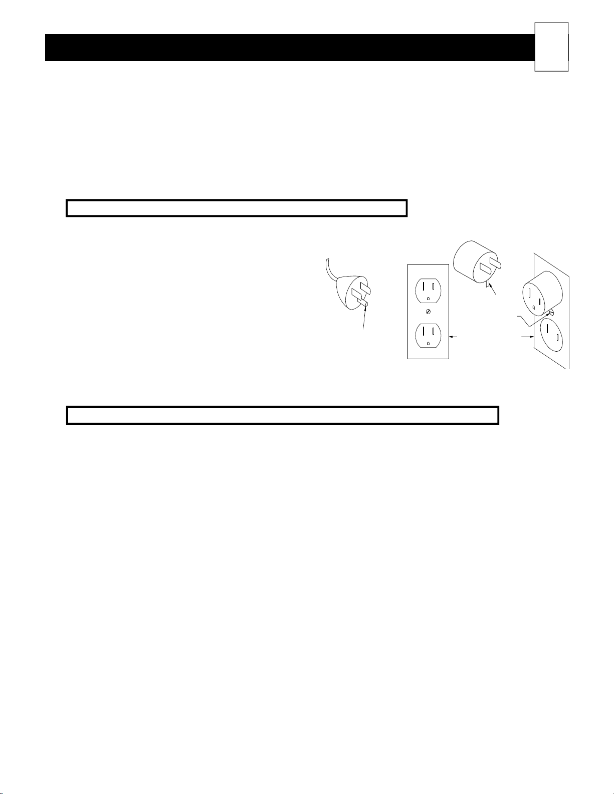
120V cord connected room heating units must only be
used with receptacles that are of the grounding
type and suitable for the load of the heater. See the
Unit Identification Label on the lower left side panel of
the heater to determine correct circuit size. (See Figure
7 for cord and receptacle requirements.)
The room heater's cord has a plug as shown in
Figure 7A. An adapter, as shown in Figure 7B, is
available for connecting three-blade grounding type
plugs to two-slot receptacles. The green grounding
means extending from the adapator
must be connected to a permanent ground, such as a proprerly grounded outlet box as shown in Figure 7C. This
adaptor should not be used if a three-slot grounded receptacle is available.
Heating element (brick core charging) control wiring connections for all room heating units
The heating elements in the heater are capable of being controlled on-peak (not able to store heat in the brick
core) via low voltage wiring, line voltage wiring, with a wireless power line carrier signal, or with a time clock.
The power line carrier transmitter and time clock are optional control devices. If either of these methods of
control are desired, they must be specified at the time of order to be included with the heater shipment.
grounding
FIGURE 7
adapter
grounding
grounding screw
grounded outlet
box
If using low voltage control, all connections to the room heating unit’s control circuit must be routed through the
low voltage raceway using the factory installed wiring. Class II (low voltage) wiring should never enter a line
voltage area of the heater, including its umbilical cord, unless it is rated for line voltage. (See Figures 13 and 14.)
If a power line carrier transmitter is being used for peak control of the room heating unit, low voltage connections
are not necessary. The transmitter can be mounted indoor or outdoor. It will transmit the peak control signal
through the entire power line system in the building. In addition to providing peak control information, it will
also transmit outdoor temperature information for automatic brick core charging. Installation instructions for this
method of control are provided with the Steffes power line carrier control system.
If using a time clock for peak control of the heater, the time clock is connected to the heater via low voltage
wiring. An installation instruction sheet is included with the time clock. Please refer to these instructions for
installation of this device inside the heater.
If line voltage control is utilized, an external switching device (such as a relay panel) is necessary to directly
control the heating element charging circuit. If relying on this method of control, the face plate on the heater will
continuously display a brick core operating mode of “C” (charge) regardless of whether it is an off-peak or on-
peak time. It is suggested that the installer change the heater so that current room temperature followed by an
“F” (Fahrenheit) or “C” (Celsius) is displayed. This is done by adjusting the data in Location 14 (L14) to d01,
or a peak control sequencer can be installed to correct the brick core operating mode display. (Order item
#1309006.)
Page 13
12
NOTE
NOTE
NOTE
4
ATTACHING THE WALL MOUNT BRACKET OR SECURITY BASE
Installing The Heater (cont'd)
For cross reference to number coded components, Refer to the Exploded View Diagram
(Figure 18) and the Heater Parts List.
The room heating unit is attached in one of two ways: wall support bracket (54) or security base (51 and 52).
Follow steps 1 and 2 regardless of the method of attachment.
Step 1 Remove the screws at the lower edge of the painted front panel (18). A plastic grill guard is provided
to protect the grill from being scratched while removing the screws.
Step 2 Pull the lower edge of the front panel forward and unhook it from the top panel (19). Carefully set
the front panel aside.
If installing a unit with a wall bracket, do step 3. If the room heating unit being installed is
equipped with a security base, proceed to step 4.
FIGURE 8
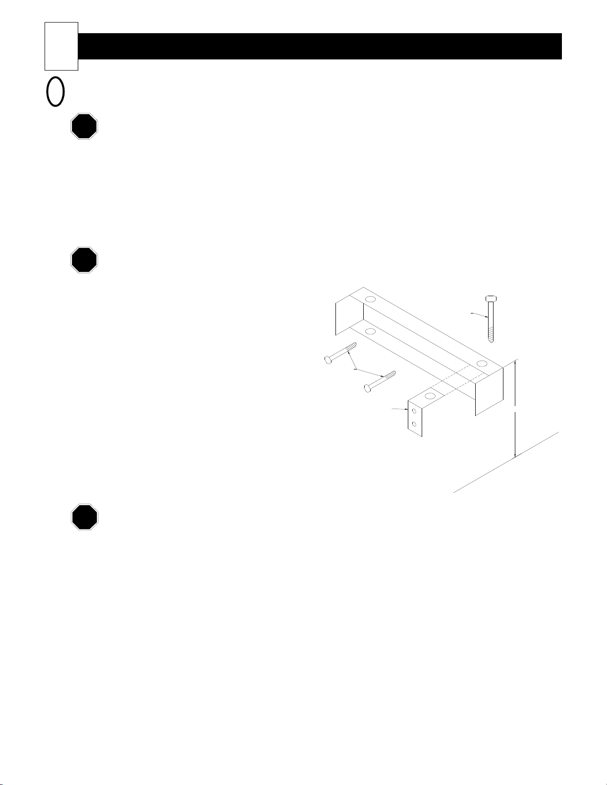
Step 3 Located in the lower right side of the heater
(near the blower) is a package containing the
hardware (53) to mount the wall support
bracket (54). The wall support bracket is
shipped on the pallet under the room heating
w
a
l
l
s
u
p
p
o
r
t
b
carriage
bolt
r
a
c
k
e
t
unit. Establish room heating unit location.
Mark the location on the wall where the wall
support bracket will be attached. The top of
lag bolts
attached to studs
this should be 23½" from the floor. It must
attach securely to wall studs. Pre-drill two
3/16" holes on each side of the bracket. Use
wall support
clip
the lag bolts provided to attach the wall
support bracket to the wall with the label on
the bracket facing upward. (See Figure 8.)
r
o
o
l
f
Use the carriage bolts to secure heater to the
bracket.
23 1/2"
The wall bracket MUST be mounted with the label facing up and the lag bolts must attach to
wood wall studs. If the wall is not a standard wood studded structure, alternate fasteners must
be used to securely attach the wall bracket.
Step 4 (Do this step only if installing a heater with a security base.) 120V plug-in cord models may come
equipped with a security base (51 and 52) rather than a wall support bracket (54). This base must
be attached to the bottom panel of the room heating unit. It is packaged inside the shipping box on
the back side of the heater. The hardware needed to mount the base to the heater is in a package
located in the lower right side of the heater (near the blower).
To install the base, gently lay the room heating unit on its back. You may find it helpful to elevate
the bottom of the room heating unit a few inches to make the installation of the base easier.
Align the holes in the security base with the pre-drilled holes in the bottom of the room heating unit.
Using the six #14 x 1¼ inch sheet metal screws provided in the hardware package, attach the security
base to the painted bottom panel (9) of the room heating unit.
After the base is attached, return the unit to its upright position and place into room location in
preparation for brick loading.
Page 14
Installing The Heater (cont'd)
NOTE
NOTE
NOTE
BRICK LOADING
5
For cross reference to number coded components, refer to the Exploded View Diagram (Figure
18) and the Heater Parts List. Refer to the Heater Specifications section in this manual for the
number of bricks required for each heater model.
Step 1 The heater must be securely mounted to the wall or to its security base (if equipped) prior to brick
loading.
Step 2 To catch brick debris, to protect the flooring, and for easy clean-up upon
completion of the installation, place the room unit's shipping box in front
of the room heater before loading the brick.
FIGURE 9
Note: Row 8 brick faces down
13
Step 3 Remove the screws on the right side of the galvanized front panel (14).
Rotate this panel to the left and remove.
Step 4 If installing a Model 2004, 2005, or 2006, remove and discard the
cardboard spacer(s) that secured the heating elements (12) during
shipment.
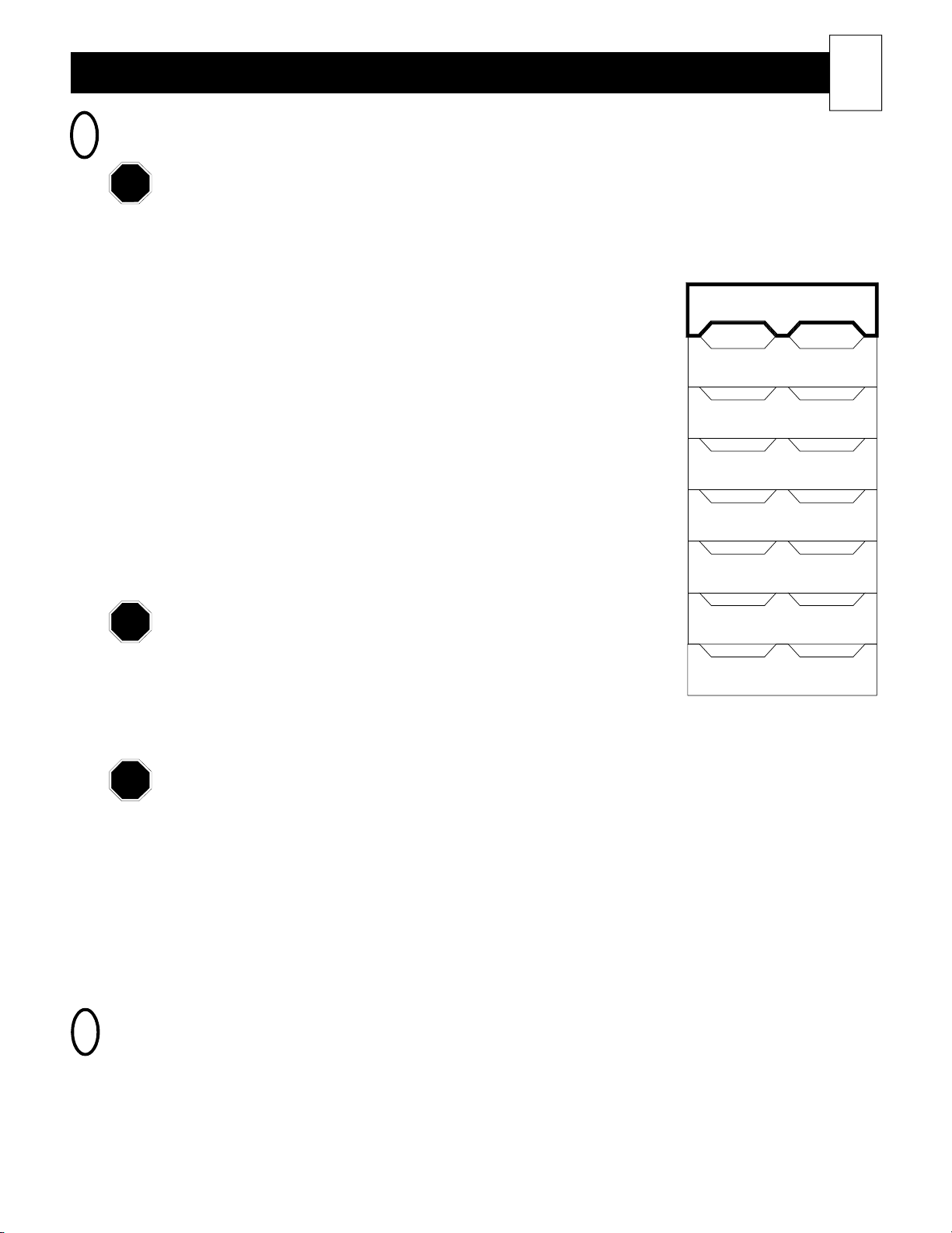
Step 5 Begin the brick loading with row one by installing the first brick (13)
face-up in the far left side (as you face the heater) of the room heater's
storage cavity. (See Figure 9 for a side view of brick stacking.) Be sure
the grooved side of the brick is up, and that it fits tight against the right
aluminized steel air channel (47).
Install bricks carefully to avoid damage to the bottom insulation
panel (49) and to the back insulation panel (23) inside the brick
cavity.
Step 6 Continue the brick loading process installing the remaining brick in row
one from right to left. Load remaining rows, one row at a time, beginning with left brick, then loading from the right to left. All bricks in rows one through seven must be
loaded with the grooved side up.
Avoid loading bricks in a fashion that would cause an uneven horizontal line across the brick
core. Bricks should line up side-to-side.
Row 7
Row 6
Row 5
Row 4
Row 3
Row 2
Row 1
Step 7 Install the eighth (top) row of bricks with the grooved side of the bricks facing down. (See Figure 9.)
A 3" x 11" metal brick installation tool is enclosed in the Owner's Manual packet to assist with
loading the top row of brick. Be careful if using this tool as the edges are sharp. To use, be sure to
bend one end down to avoid contact with the sharp edge. Lay the metal tool over the far right brick in
row 7 with the bent end out. Slide a brick over the metal piece and into position. Pull the metal piece
out. Continue this procedure until the entire top row of bricks are installed.
IMPORTANT: The top bricks (row 8) must face downward.
Step 8 Once all bricks are loaded, replace the galvanized front panel (14).
SETTING THE METHOD OF BRICK CORE CHARGE CONTROL
6
With automatic charge control, outdoor temperature information can be supplied to the room heating unit in one
of two ways: Steffes power line carrier system or direct wired outdoor sensor.
The room heating unit is shipped from the factory set for automatic charge control for use with the Steffes power
line carrier control system. The heater comes preset to start charging at an outdoor temperature of 60oF (15.6oC)
and to be at a full core charge level at 20oF (-6.7oC). (The installing electrical contractor or power company
personnel will have more information on how to adjust these temperatures to more accurately reflect the climate
in your area, if necessary.)
Page 15
14
NOTE
NOTE
Power Line Carrier and Automatic Charge Control
The Steffes power line carrier (PLC) control system has the capability of sending outdoor temperature information, WIRELESS, to an unlimited number of 2000 series heater for automatic charge control. No direct wiring to
the heater is required with a PLC control system. The outdoor temperature information is transmitted through the
entire power line system in the home or building. The heater's built-in receiver will pick up the signals being
transmitted on the power line and respond accordingly. PLC control is available with the use of the Steffes PLC
Transmitter or the Steffes Comfort Control Relay Panel (CCRP). Only one PLC system is needed in an installation. If using the PLC Transmitter and installing it outdoors, an outdoor sensor may be utilized but is not required. If installing the PLC Transmitter indoors or if using the CCRP's built-in PLC system, one external
outdoor temperature sensor is required for automatic charge control. An installation procedure manual will
accompany the PLC Transmitter and CCRP. Please refer to these instructions for installation of either device.
Direct Wired Outdoor Sensor and Automatic Charge Control
An outdoor sensor can be direct wired into each room heating unit using low voltage wire. One outdoor sensor is
required for each room heating unit that is installed. An installation instruction sheet is included with the outdoor
sensor. Please refer to these instructions for installation of this device. (Order item #1302026.)
Installing The Heater (cont'd)
If using a PLC signal for transmitting outdoor temperature information, Dip Switch #6 inside the
heater on its microprocessor board must be in the "OFF" position. (Refer to the Typical Control Wiring Diagrams section for more information on the heater's dip switches.)
If using a direct wired outdoor sensor for transmitting outdoor temperature information, Dip
Switch #6 inside the heater on its microprocessor board must be in the "ON" position. (Refer to
the Typical Control Wiring Diagrams section in this manual for more information on the heater's
dip switches.)
Manual Charge Control
No additional devices are required for brick core charging if the charge level is to be set manually by the user.
Since the heater comes factory preset for automatic charge control, Location 19 (L19) must be adjusted to
manual control. Location 7 (L07) should also be adjusted so that both room and brick core temperature can be
adjusted after the M button is pressed for a few seconds. (The installing electrical contractor or power company
personnel will have more information on how to make these adjustments.)
REMOTE ROOM SENSOR (OPTIONAL)
7
All 2000 series room heating units come factory equipped with a built-in room temperature sensor. This sensor is
installed in the electrical compartment on the right side panel of the heater, near the floor. In installations where
it is desired to monitor temperature at another point in the room, a remote room temperature sensor may be used.
If a remote sensor is installed, the built-in sensor is disconnected. The remote sensor will provide the room
temperature information to the heater. With either option, current room temperature is dislayed on the heater's
face plate. An installation instruction sheet is included with the remote room sensor. Please refer to these
instructions for installation of this device. (Order item #1302024.)
INSTALLER'S INSTRUCTIONS FOR SETTING HEATER
8
OPERATION FUNCTIONS
The heater is shipped from the factory preset with standard operating functions. The owner should not have to
make adjustments; however, if it is necessary to do so, the Advanced Heater Operation section of this manual
explains those functions that are owner accessible and how to change them. The heater also contains functions
related to power company control that are explained in a Supplemental Installer's Guide. This guide is only
available to power company officials and factory certified installers.
Page 16

Installing The Heater (cont'd)
NOTE
NOTE
INSTALLER'S FINAL CHECKOUT PROCEDURE
9
For cross reference to number coded components, refer to the Exploded View Diagram (Figure 18) and
Heater Parts List in the Owner’s Manual.
____ 1. De-energize the electrical circuit(s) feeding the heater. Place the control circuit board (2) in the service
position by sliding it off its mounting screws and hooking it on these same screws using the eyelets provided
on the front of the mounting plate (1). Inspect all field installed electrical connections to ensure they are tight
and that all wires are routed correctly. Keep in mind that ETS devices run for long periods of time at high
electrical loads. Poor or marginal electrical connections will cause the connection to overheat and fail.
Class II (low voltage) wiring or any wiring not rated for line voltage should never be installed
in a line voltage area.
____ 2. Check the damper system to ensure the damper operates freely and that there is no debris in this area which
could inhibit its operation. To do so, manually press the damper lever extending from the damper assembly
(34). Be careful not to bend the damper actuator (40). If the damper is not free, remove the blower and
clean any debris from that area.
____ 3. Check the settings of the dip switches on the back of the control circuit board (2). In applications where the
heater is being controlled by the power line carrier transmitter, typically all dip switches will be set in the
“OFF” position. If using a hard wired outdoor temperature sensor for automatic charge control, set dip
switch 6 on the back of the circuit board (2) to the “ON” position. With manual charge control, dip switch 6
must be set to the “OFF” position. (The Supplemental Installer’s Guide provides more information on the
dip switches.)
15
If manual charge control is being utilized, the data in Location 19 (L19) must be set to d02. It
is the factory recommendation to also set the data in Location 7 (L07) to d02 so that both
room and brick core temperatures can be adjusted after the M button is pressed for a few
seconds. It may be necessary to unlock these locations to make the change. This is done by
changing the data in Location 39 (L39) to d20. Remember to reset the lock when adjustments
are complete.
____ 4. Energize the heater and check blower (37) operation. If the blower is operating, adjust the room temperature
set point below the actual room temperature. To make certain the blower will start in low speed, set the room
temperature one degree above actual room temperature. To check to ensure the heater’s blower will operate
in high speed, adjust the room temperature set point to at least five degrees above actual room temperature.
____ 5. Set the heater to the charge mode and adjust the room temperature so the blower is operating. With a clamp-
on amp meter, check for proper amperage draw on the charging circuit(s). On Models 2002 and 2003, this is
done at B1 terminal block position. On Models 2004, 2005, and 2006, this is done by totalling the readings
from the B1 and R1 terminal block positions (30). Refer to the Unit Identification Label on the lower left
side panel of the heater for information on voltage and input wattage of the heater being installed. Use the
Charging Circuit Amperage Draw table on the next page for reference to the correct amperage for the
specific heater being installed.
Page 17
16
NOTE
____ 6. Make certain all fuses and/or circuit breakers are labeled in the distribution panel. Use the Steffes orange
panel label provided in the wall mounting bracket hardware package (53).
Installing The Heater (cont'd)
CHARGING CIRCUIT AMPERAGE DRAW
INPUT WATTAGE VOLTAGE AMP DRAW
1.32 120 11.0
2.4 240 10.0
3.0 240 12.5
3.6 240 15.0
4.5 240 18.75
4.8 240 20.0
5.4 240 22.5
6.0 240 25.0
7.2 240 30.0
7.5 240 31.25
9.0 240 37.5
(AMP draw is calculated by taking the total input wattage divided by the input voltage.
Allow +/- 5% tolerance at nominal input voltage.)
This label is important since the heater may be connected to more than one branch circuit.
____ 7. Check all other system controls for proper operation.
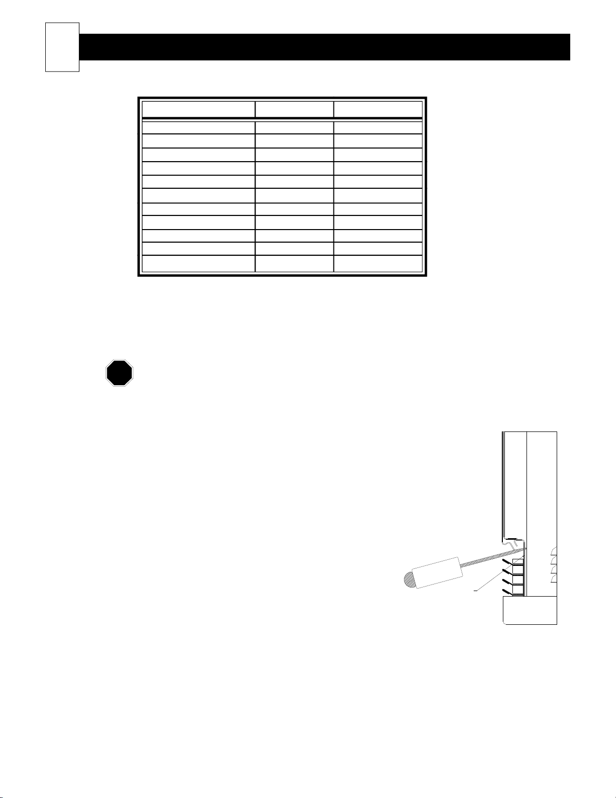
FIGURE 10
____ 8. De-energize the heater. Return the control circuit board (2) to its
original position. Install the painted front panel (18). To assist
in aligning the front panel with the top panel (19) and to make it
easier to install the front panel screws, lifting slots have been
provided in the galvanized base tray (57), one at each end. Place
the tip of a screwdriver in one of these slots and lift upward. (See
Figure 10.) Install the screw. Do the same on the other end. Be
sure to use the plastic grill guard when installing the screws to
protect the grill (10) from being scratched. The grill guard
should be removed after the installation. Energize the system.
____9. Present owner with the manual and warranty information. The
owner's registration card must be completed and returned to
Steffes Corporation to ensure warranty coverage. The owner
should retain the top portion of the card for their records. The
installer should retain the Supplemental Guide.
____ 10. Take the time needed to instruct the owner on how to operate the system. Many service calls with new ETS
systems are a result of owner confusion on equipment operation. The time spent in training will greatly
reduce the chance of a call back.
GALVINIZED
BASE TRAY
SIDE VIEW
Page 18
Heater Wiring
NOTE
NOTE
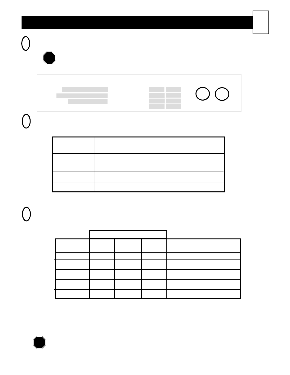
ROOM HEATING UNIT IDENTIFICATION LABEL
1
All heaters are UL and cUL safety listed. The listing identification label is located on the lower
left side panel of the heater.
FIGURE 11
17
Steffes Corporation, Dickinson, ND
Model Charge Crct #1
S/N Charge Crct #2
Options Fan/Cntrl Crct
U.S. Patent #5.042.081
ROOM HEATING UNIT UMBILICAL CORD
2
Manufactured in North America
Temp Cntrl Crct
VAC Wat ts
Electric
Air Heater
U
L
LISTED
3P23
(WIRING HARNESS) COLOR CODE
TABLE 1
WIRE COLOR CIRCUIT DESCRIPTION
Black Models 2002 & 2003: All heating elements.
Models 2004, 2005, & 2006: Upper heating elements.
Red Models 2004, 2005, & 2006: Lower heating elements.
Blue Blower and control circuit.
Refer to the Unit Identification Label on the lower left side of room heating unit
for proper blower and heating element voltages. (See Figure 11.)
FIELD CONNECTION WIRE AND CIRCUIT BREAKER
3
SIZING GUIDE
TABLE 2
U
L
C
MAXIMUM kW
MAXIMUM CIRCUIT
WIRE SIZE 240VAC 277VAC 208VAC BREAKER SIZE (240V Only)
#14 AWG 2.8 3.3 2.4 15
#12 AWG 3.8 4.4 3.3 20
#10 AWG 5.7 6.6 4.9 30
#8 AWG 7.6 8.8 6.6 40
#6 AWG 11.5 13.2 9.9 60
Use copper wire rated at 75o C minimum only.
Disclaimer: The field connection wire and breaker size guide reflects only the code interpretation of Steffes
Corporation. It is the responsibility of the installer to follow all applicable codes and regulations for
the installation.
Models 2004, 2005, and 2006 units are equipped with a two-circuit element feed option. If dual feed is used,
refer to the Unit Identification Label located on the left side panel for proper sizing of each circuit. (See Figure
11.) If single-feed connection is used, size circuit for total wattage. (Charge Circuit #1 + Charge Circuit
#2 = Total Wattage.)
Page 19
18
NOTE
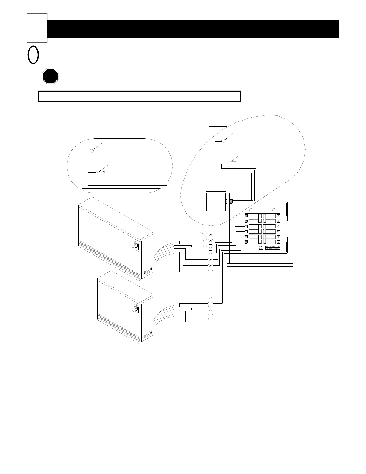
TYPICAL SYSTEM WIRING DIAGRAM
4
Heater Wiring (cont'd)
Connections shown are for 230 VAC blowers. Refer to the Unit Identification Label on the lower left
side panel of the room heating unit for proper blower and heating element voltages of your heater.
Low Voltage Wired Outdoor Sensor and Load Management Control
FIGURE 12
SEE NOTE 3
SEE NOTE 2
OUTDOOR SENSOR
(CONNECTED WITH 18-2 CABLE)
LOAD MANAGEMENT
CONTROL SWITCH
(CONNECTED WITH 18-2 CABLE)
PLC
TRANSMITTER
OUTDOOR SENSOR
(CONNECTED WITH 18-2 CABLE)
LOAD MANAGEMENT
CONTROL SWITCH
(CONNECTED WITH 18-2 CABLE)
240VAC SOU RCE
4
1515
20
5
20
6
30
15
MULTIPLE
CIRCUIT
CONNECTED
SINGLE
CIRCUIT
CONNECTED
SEE NOTE 1
GREEN
BLACK
GREEN
RED
RED
BLACK
BLACK
BLUE
BLUE
BLUE
BLACK
BLUE
1
2
3
NOTE 1: Models 2004, 2005, and 2006 are equipped with a two-circuit element feed option.
NOTE 2: Do not make these connections if using the Steffes power line carrier (PLC) control
system to control the heater(s) in the installation. The outdoor sensor is an optional
feature. (Order item #1302026.)
NOTE 3: The Steffes Power Line Carrier (PLC) system is an optional heater control method.
PLC control is available with the use of the Steffes PLC Transmitter or the Steffes
Comfort Control Relay Panel (CCRP). If using the PLC Transmitter and installing
it outdoors, an outdoor sensor for automatic brick core charge regulation is not
required. If installing the PLC Transmitter indoors or if using the PLC control
system built into the CCRP, one external outdoor sensor is required for automatic
brick core charge regulation.
Page 20

Heater Wiring (cont'd)
NOTE
HEATER DIP SWITCH SETTINGS
5
The brick core charging of the 2000 series room heating unit is capable of being controlled by low voltage
wiring, by line voltage wiring, by a time clock or by a power line carrier signal (wireless control) with the use of
the Steffes power line carrier (PLC) control system.
Depending on which method of heating element control is being used, the unit configuration dip switches will
need to be set accordingly. (See Figure 13 for location of these dip switches in the heater.) The function of each
dip switch is as follows:
Dip Switch #1 = Invert Peak Signal (Should be "ON" if using a time clock for control purposes.)
Dip Switch #2 = NOT USED (Should always remain in "OFF" position.)
Dip Switch #3 = Invert Occupied/Not Occupied Signal (Room Temperature Set back)
Dip Switch #4 = Invert Anticipated (Pre-Peak) Signal
Dip Switch #5 = Enable Auxiliary Heat Call Feature
Dip Switch #6 = Automatic Charge Control Configuration (Should be "ON" if a direct wired outdoor sensor is being
used for automatic brick core charge regulation.)
Dip Switch #7 = Security (Editing Control) Mode
Dip Switch #8 = Used for factory purposes ONLY. (Must always remain in "OFF" position.)
If the dip switch button is set in the up position, the dip switch is in the "ON" (activated) position.
If the dip switch button is set in the down position, the dip switch is in the "OFF" (deactivated)
position. (See Figure 13 for location of the dip switches in the heater.)
19
Page 21
20
NOTE
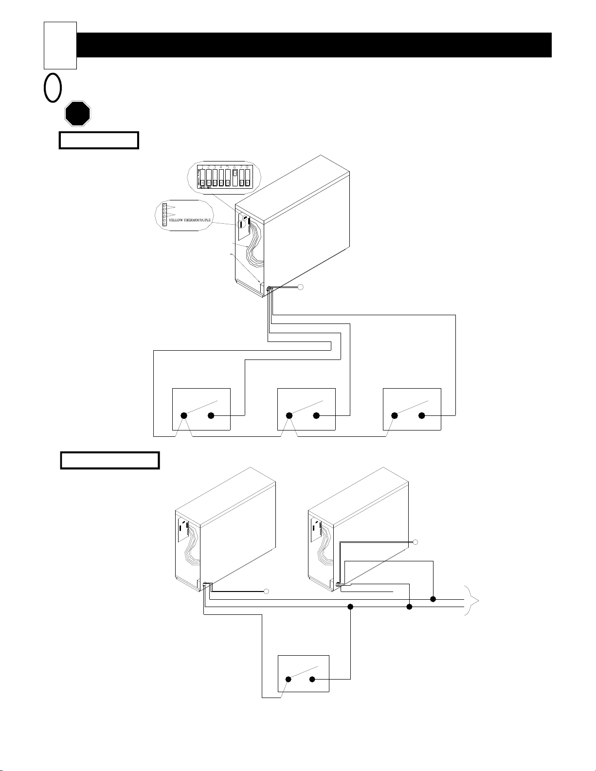
TYPICAL LOW VOLTAGE CONTROL WIRING DIAGRAMS
6
Heater Wiring (cont'd)
Never install any wiring in a line voltage area unless the wire is rated for line voltage.
SINGLE UNIT
UNIT CONFIGURATOR
SWITCHES (SEE NOTE 1)
ROOM SENSOR
OUTDOOR SENSOR
RED THERMOCOUPLE
WIRING HARNESS
LOW VOLTAGE
JUNCTION BOX
PEAK
CONTROL SWITCH
FIGURE 13
R
E
T
A
E
H
F
O
K
C
A
B
OUTDOOR SENSOR
ORANGE (ROOM TEMPERATURE SETBACK)
BLUE/YELLOW (PRE-PEAK)
BLUE/WHITE (PEAK)
BLUE (L.V. POWER)
PRE-PEAK
CONTROL SWITCH
(OPTIONAL) (OPTIONAL)
ROOM TEMPERATURE
CONTROL SWITCH
SETBACK
R
E
T
A
E
FIGURE 14
DIRECT WIRED
OUTDOOR SENSOR
(OPTIONAL) - SEE NOTE 1
PEAK
CONTROL SWITCH
C
A
B
E
H
F
O
#
K
-
2
#
BLUE (NOT USED)
R
E
T
A
6
BLUE/WHITE
DIRECT WIRED
OUTDOOR SENSOR (OPTIONAL) - SEE NOTE 1
YELLOW
TO NEXT HEATER
(6 HEATERS MAX)
MULTIPLE UNITS
F
O
K
C
1
A
#
B
YELLOW (L.V. COMMON)
BLUE/WHITE (PEAK)
BLUE (L.V. POWER)
H
NOTE 1: If using a direct wired outdoor temperature sensor for automatic charge control, one outdoor
sensor is required for each heater that is installed.
NOTE 2: Dip switch #6 must be turned "ON" only if connecting a hard wired outdoor temperature sensor.
Page 22
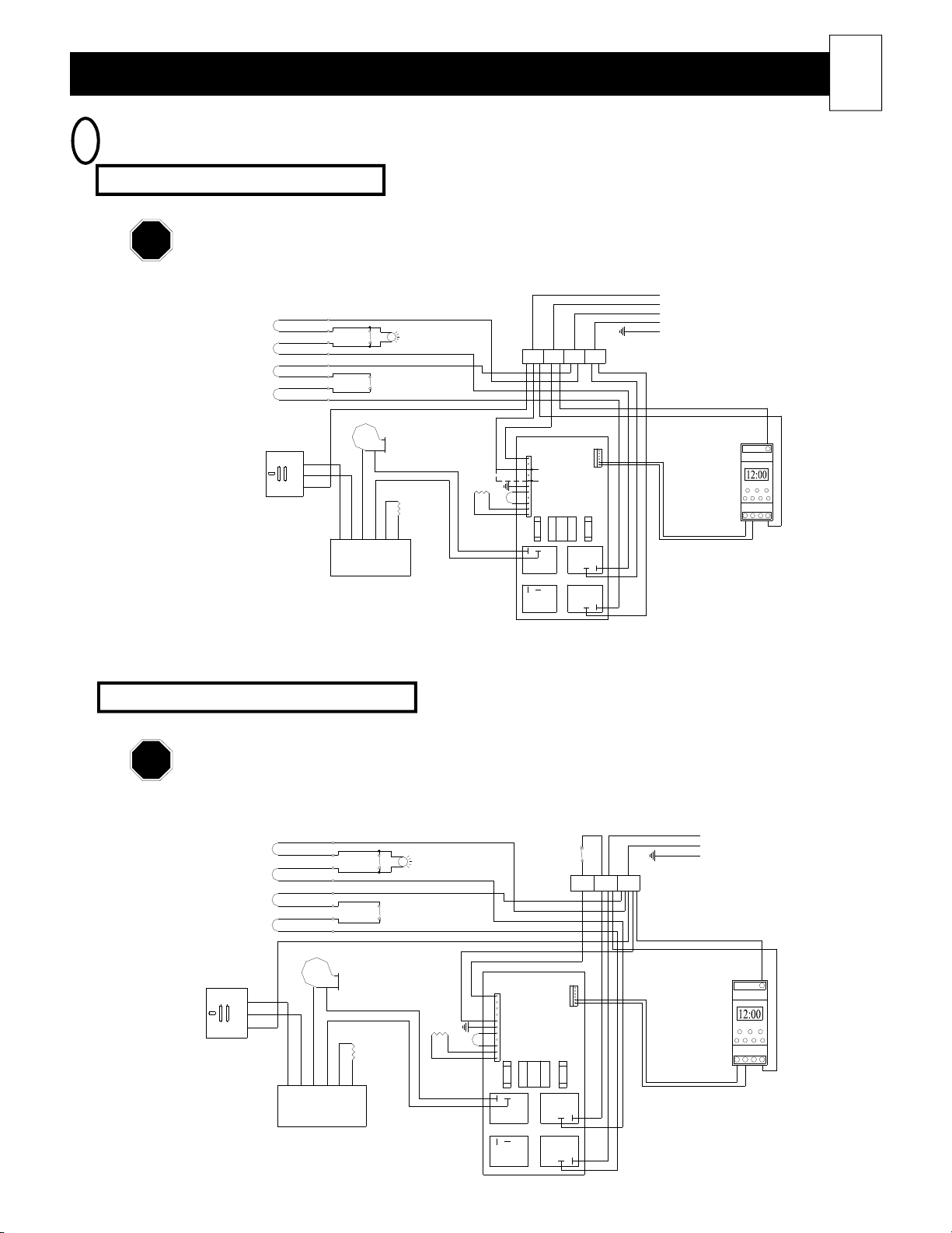
Heater Wiring (cont'd)
NOTE
NOTE
ROOM HEATING UNIT LINE VOLTAGE WIRING DIAGRAMS
7
Models: 2002 & 2003 (direct wired)
Connections shown are for 230 VAC blowers. Refer to the Unit Identification Label on the lower
left side panel of the room heating unit for proper blower and heating element voltages of your
heater.
FIGURE 15
HEATING ELEMENTS
CHARGING
CHARGING
LIMIT
SERVICE
LIGHTLIMIT
BLACK
BLACK
RED
RED
F2 B1 B2F1
CONTROLS AND
BLUE
BLUE
FAN CIRCUIT
BLACK
BLACK
CHARGE CIRCUIT
GREEN
21
(See Note 1)
OUTPUT
BOARD
YRB
FAN
B O OFRY
DAMPER BOARD
DAMPER
CONTROL
RESISTOR
FAN
SPEED
RESISTOR
WHITE/BL UE
BLACK/Y ELLOW
RED
OPTIONAL
COM
BLACK
240 VOLT
120 VOLT
R
E
M
3
A
NO
FAN
RELAY
NOT
CONNECTED
1
R
O
F
S
N
A
A
R
T
ELEMENT
RELAY
NO
ELEMENT
RELAY
NO
COM
COM
TIME CLOCK
BLUE/WHITE
BLUE
1
L
23N
NOTE 1: If installing a unit configured with a 115VAC blower, and the Steffes power line carrier (PLC)
control system is being utilized, the F2 terminal block position must be the hot (ungrounded) leg.
Models: 2002, & 2003 (cord connected)
Connections shown are for 115 VAC blowers. Refer to the Unit Identification Label on the
lower left side panel of the room heating unit for proper blower and heating element voltages of
your heater.
FIGURE 16
BLACK
WHITE
POWER CORD
GREEN
HEATING ELEMENTS
CHARGING
CHARGING
LIMIT
SERVICE
LIGHTLIMIT
BLACK
BLACK
RED
RED
TIP
SWITCH
T1 L1 L2
OUTPUT
BOARD
YRB
FAN
B O OFRY
DAMPER BOARD
DAMPER
CONTROL
RESISTOR
FAN
SPEED
RESISTOR
WHITE/BLUE
BLACK/YELL OW
NO
COM
3
A
FAN
RELAY
NOT
CONNECTED
OPTIONAL
TIME CLOCK
R
E
M
1
R
O
F
S
N
A
A
R
T
ELEMENT
RELAY
NO
COM
ELEMENT
RELAY
NO
COM
BLUE/WHITE
BLUE
1
L
23N
Page 23
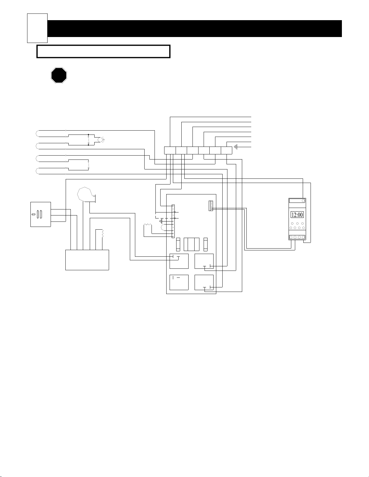
22
NOTE
Heater Wiring (cont'd)
Models: 2004, 2005 & 2006 (direct wired)
Connections shown are for 230 VAC blowers. Refer to the Unit Identification Label on the
lower left side panel of the room heating unit for proper blower and heating element voltages of
your heater.
HEATING ELEMENTS
CHARGING
LIMIT LIGHT
CHARGING
LIMIT
SERVICE
BLACK
BLACK
RED
RED
FIGURE 17
F1 B2B1R2R1F2
CONTROLS AND
BLUE
BLUE
FAN CIRCUIT
RED
RED
CHARGE CIRCUIT #1
BLACK
BLACK
CHARGE CIRCUIT #2
GREEN
(See Note 1)
OUTPUT
BOARD
FAN
RED
BLACK
OPTIONAL
TIME CLOCK
L
FAN
B R Y
DAMPER
CONTROL
RESISTOR
Y R F OOB
DAMPER BOARD
SPEED
RESISTOR
WHITE/BLUE
BLACK/YELLOW
NO
COM
240 VOLT
120 VOLT
3
A
FAN
RELAY
NOT
CONNECTED
1
N32
R
E
M
1
R
O
F
S
N
A
A
R
T
ELEMENT
RELAY
NO
COM
ELEMENT
RELAY
NO
COM
BLUE/WHITE
BLUE
NOTE 1: If installing a unit configured with a 115VAC blower, and the Steffes power line carrier (PLC) control
system is being utilized, the F2 terminal block position must be the hot (ungrounded) leg.
Page 24
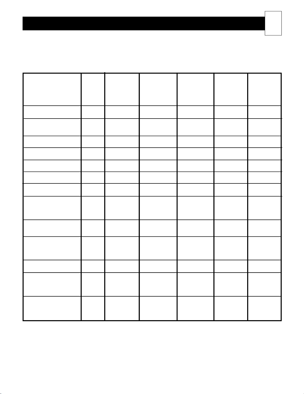
Room Heating Unit Specifications
MODEL 2002 2002 2003 2004 2005 2006
plug-in
Length - inches 30 30 37 44 51 58
Height - inches 24.5 24.5 24.5 24.5 24.5 24.5
Depth - inches 10.5 10.5 10.5 10.5 10.5 10.5
(w/out wall bracket)
Number of Bricks 16 16 24 32 40 48
Number of Brick Boxes 4 4 6 8 10 12
Weight of Heater - lbs 105 91 112 126 145 164
23
Weight of Bricks - lbs 176 176 264 352 440 528
Installed Weight - lbs 281 267 376 478 585 692
*Inputs Available - kW
120V 1.32 N/A N/A N/A N/A N/A
208V, 240V, 277V N/A 2.4, 3.0, 3.6 3.6, 4.5, 5.4 4.8, 6.0, 7.2 6.0, 7.5, 9.0 7.2, 9.0
*Element Voltage 120 240 (std) 240 (std) 240 (std) 240 (std) 240 (std)
208 & 277 opt 208 & 277 opt 208 & 277 opt 208 & 277 opt 208 & 277 opt
*Blower Voltage 115 230 (std) 230 (std) 230 (std) 230 (std) 230 (std)
115, 208, & 115, 208, & 115, 208, & 115, 208, & 115, 208, &
277 opt 277 opt 277 opt 277 opt 277 opt
Number of Blowers 1 1 1 1 1 1
Blower Wattage
Minimum 30 30 30 30 30 30
Maximum 120 120 120 120 120 120
Storage Capacity
kWh 13.5 13.5 20.25 27 33.75 40
BTU 46,062 46,062 69,093 92,124 115,155 136,480
*Refer to the Unit Identification Label on lower left side panel of the room heating unit for data specific to your
heater. (See Figure 11.)
Page 25
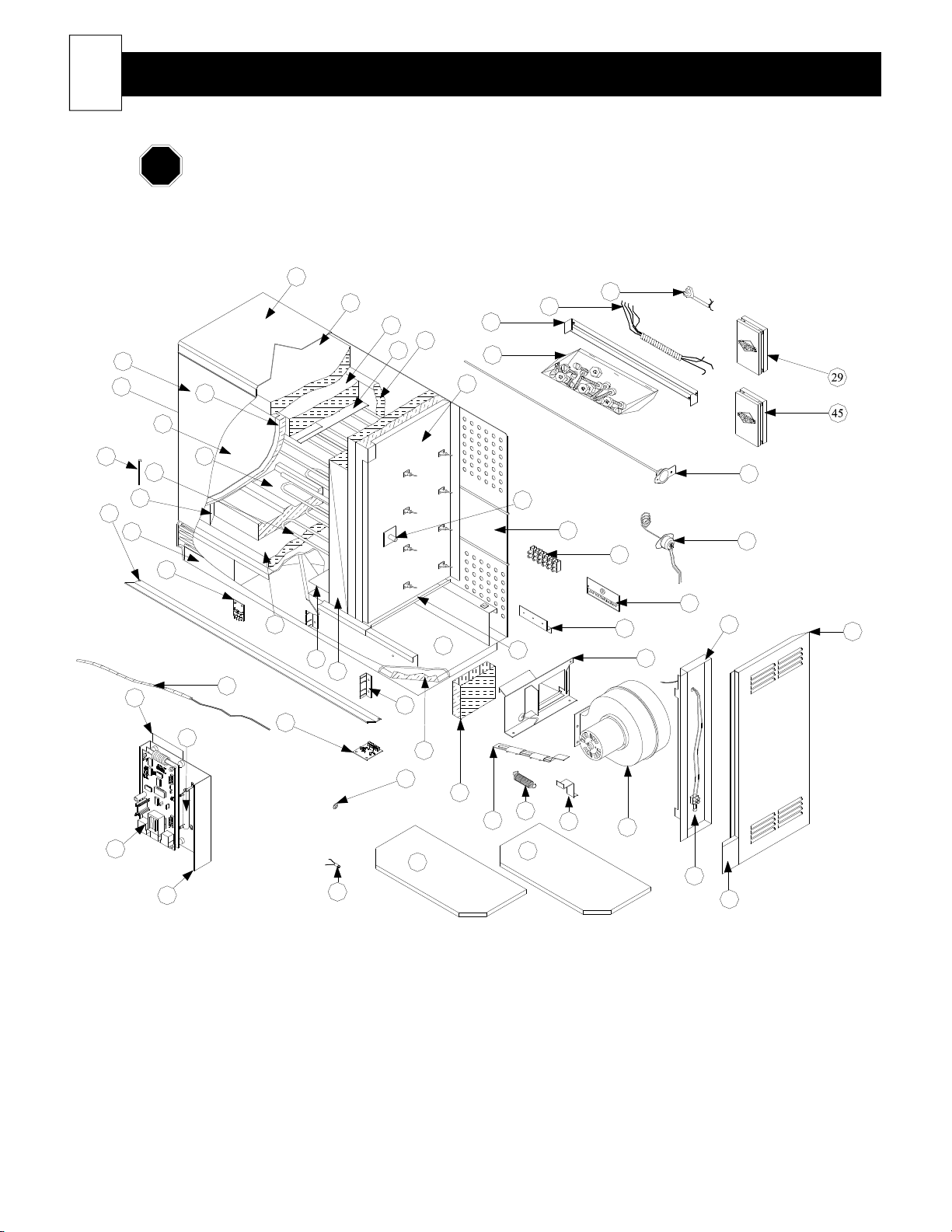
24
NOTE
Exploded View Heater Diagram
When ordering replacement parts, please include model number and serial number of the heater.
FIGURE 18
19
20
21
23
18
17
15
12
11
10
9
4
16
14
13
8
49
42
5
48
3
47
22
57
46
43
54
53
24
55
26
35
56
25
27
30
31
33
34
28
6
32
44
2
1
50
41
39
40
52
38
51
37
7
36
Page 26
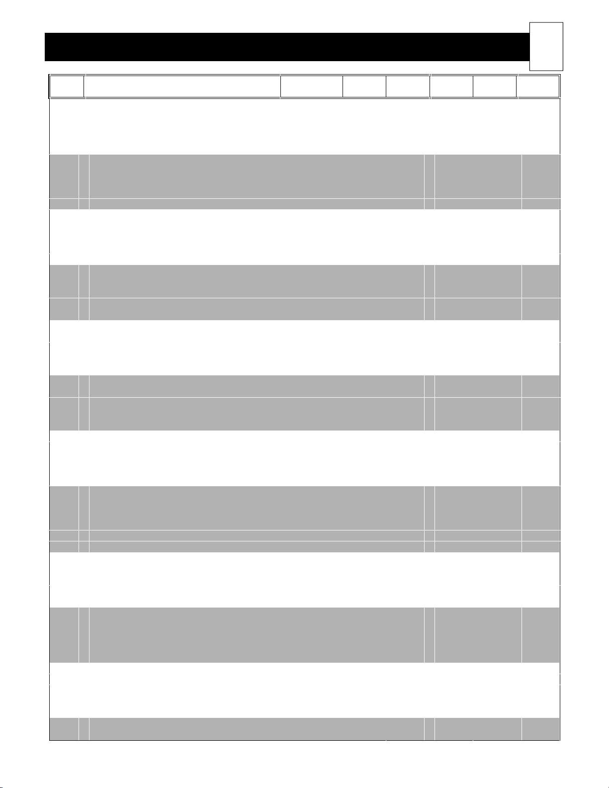
Heater Parts List
25
REF
NO.
1. Control Circuit Board Mounting Plate 5940308 5940308 5940308 5940308 5940308 5940308
2. Control Circuit Board Assy (Microprocessor) 1043012 1043012 1043012 1043012 1043012 1043012
3. *Blower Resistor (240VAC) 1017011 1017050 1017016 1017016 1017046 1017046
4. Face Plate 1159032 1159032 1159032 1159032 1159032 1159032
5. Brick Core Thermocouple (Sensor) 1043004 1043004 1043005 1043005 1043005 1043005
6. Room Temperature Sensor Mounting Panel 5949087 5949087 5949087 5949087 5949087 5949087
7. Built-in Room Temperature Sensor Assembly 1040360 1040360 1040362 1040362 1040362 1040362
8. Output Temperature Sensor Circuit Board 1040388 1040388 1040388 1040388 1040388 1040388
9. Painted Panel, Bottom 5943060 5943060 5943062 5943064 5943066 5943068
10. Grill Slats 5943100 5943100 5943102 5943104 5943106 5943108
11. Aluminized Air Channel, Left 5949028 5949028 5949028 5949028 5949028 5949028
12. *Heating Elements Contact factory with serial number of heater.
13. Heat Storage Brick 5903010 5903010 5903010 5903010 5903010 5903010
14. Galvanized Panel, Front 5943010 5943010 5943012 5943014 5943016 5943018
15. Grill Pin 5943099 5943099 5943099 5943099 5943099 5943099
16. Insulation Panel, Front 1053010 1053010 1053012 1053014 1053016 1053018
17. Painted Panel, Left 5943020 5943020 5943020 5943020 5943020 5943020
18. Painted Panel, Front 5943000 5943000 5943002 5943004 5943006 5943008
19. Painted Panel, Top 5943050 5943050 5943052 5943054 5943056 5943058
20. 1 ½” Blanket Insulation, Outer 1050073 1050073 1050074 1050075 1050076 1050077
21. 1 ½” Blanket Insulation, Inner 1050082 1050082 1050083 1050084 1050085 1050086
22. Aluminized Air Channel, Top 5949060 5949060 5949062 5949064 5949066 5949068
23. Insulation Panel, Back 1053010 1053010 1053012 1053014 1053016 1053018
24. Galvanized Panel, Right 5943040 5943040 5943040 5943040 5943040 5943040
25. Core Charging High Limit Guide Tube 1105016 1105016 1105018 1105020 1105022 1105024
26. Thermocouple Tube 5943222 5943222 5943220 5943220 5943220 5943220
27. Galvanized Panel, Back 5943070 5943070 5943072 5943074 5943076 5943078
28. Core Charging High Limit Switch 1040406 1040406 1040406 1040408 1040408 1040410
29. Outdoor Temperature Sensor, Optional 1302026 1302026 1302026 1302026 1302026 1302026
30. Terminal Block Kit 1040242 1040242 1040242 1040243 1040243 1040243
31. Low Voltage Raceway Cover 5943216 5943216 5943216 5943216 5943216 5943216
32. Painted Panel, Right 5943030 5943030 5943030 5943030 5943030 5943030
33. Terminal Block Mounting Bracket 5943212 5943212 5943212 5943212 5943212 5943212
34. Damper Assembly 1043010 1043010 1043010 1043010 1043010 1043010
35. Galvanized Plate, Bottom 5943080 5943080 5943082 5943084 5943086 5943088
36. Grill End Bracket, Right 5940998 5940998 5940998 5940998 5940998 5940998
“ Grill End Bracket, Left 5940996 5940996 5940996 5940996 5940996 5940996
37. *Blower Assembly (230VAC) 1021001 1021001 1021001 1021001 1021001 1021001
38. Damper Resistor Mount 5943226 5943226 5943226 5943226 5943226 5943226
39. Fan Mounting Spring 1159006 1159006 1159006 1159006 1159006 1159006
40. Damper Actuator Assembly 1043007 1043006 1043006 1043006 1043006 1043006
41. Damper Assembly Insulation N/A N/A N/A N/A N/A N/A
42. Base Cap Insulation 5943130 5943130 5943130 5943130 5943130 5943130
43. 1" Base Insulation 1050066 1050066 1050067 1050068 1050069 1050070
44. Element Push Nut 1151015 1151015 1151015 1151015 1151015 1151015
45. Remote Room Temperature Sensor (optional) 1302024 1302024 1302024 1302024 1302024 1302024
46. Grill Support Rail 5943024 5943024 5943024 5943024 5943024 5943024
47. Aluminized Air Channel, Right 5949026 5949026 5949026 5949026 5949026 5949026
48. Damper Circuit Board 1159044 1159044 1159044 1159044 1159044 1159044
49. Insulation Panel, Bottom 1053020 1053020 1053022 1053024 1053026 1053028
50. *Red Service Light (240VAC) 1015021 1015021 1015021 1015021 1015021 1015021
51. Security Base Shell 5942114 N/A N/A N/A N/A N/A
52. Security Base Filler 1190023 N/A N/A N/A N/A N/A
53. Wall Bracket Hardware Kit 1190032 1190032 1190032 1190032 1190032 1190032
54. Wall Support Bracket 5943200 5943200 5943202 5943204 5943206 5943208
55. Umbilical Cord N/A 1040600 1040600 1040602 1040602 1040602
56. Cord Connect 1015000 N/A N/A N/A N/A N/A
57. Galvanzied Base Tray 5943110 5943110 5943112 5943114 5943116 5943118
*Optional voltages or wattages are available. Contact factory with model number and serial number of the heater.
Description
2002 Plug-in
Item #
2002
Item #
2003
Item #
2004
Item #
2005
Item #
2006
Item #
Page 27
26
CAUTION
The data for the heaters operating functions are stored in specific locations in the heater's microprocessor and can be
accessed through the control panel. All functions should be adjusted by the installer for the application at the time of
the installation. The only adjustment the user should have to make is setting the room temperature which is typical
with any heating system. If the ETS system has been set for manual charge control, the user will also need to adjust
the brick core charge level on occasion.
Usually, the owner can access heater data stored in Locations 0 through 10 (L00 - L10) and can make adjustments if
desired. When adjusting or viewing any of the heater data, the MODE digit will indicate an "L" or a "d".
L = Indicates the location of the heater function that is being viewed or changed. (See Figure 19.)
d = Indicates the specific data that is stored in a location. This data determines how the heater will
Advanced Heater Operation
The room heating unit is shipped from the factory preset with standard operating functions. Adjustments should not have to be made; however, if you find it is necessary to do so, this section contains
the information for changing the standard configuration. Please proceed with caution when making
the adjustments.
function. (See Figure 20.)
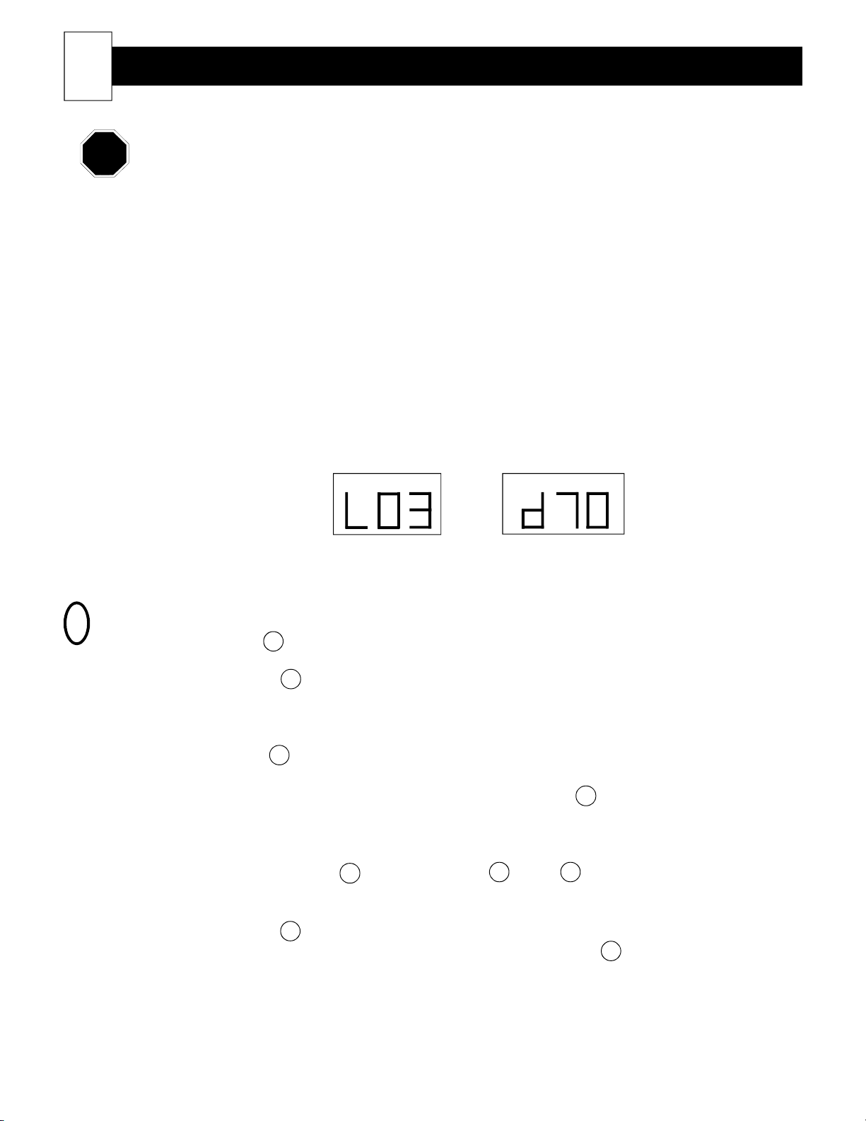
Figure 19
MODE TEMPERATURE
Figure 20
MODE TEMPERATURE
In this example,
you are in function
location 3.
HOW TO CHANGE THE HEATER'S OPERATION
1
Step 1 Hold the M button until a "d" appears on the MODE digit.
Step 2 Release the M button. The face plate will display "L00". The "L" under the MODE digit
indicates a specific location of the heater's microprocessor, and the "00" indicates the location
number.
Step 3 Press the arrow button until the location to be edited is reached.
Step 4 After reaching the location to be edited, press and hold the M button. A "d" under the
MODE digit and two numbers under the TEMPERATURE digits will be displayed. This is the
data that is currently stored in this specific location.
Step 5 Continue to hold the M button and use the or the arrow buttons to change the data
to the desired value.
Step 6 Release the M button. The face plate will automatically return to displaying the current room
temperature after the adjustments have been made, or press the arrow button until the
current room temperature is displayed. Any changes made to the heater settings will be stored
in the locations that have been adjusted.
In this example, the
data stored in a
location is 70.
Page 28
Advanced Heater Operation (cont'd)
NOTE
NOTE
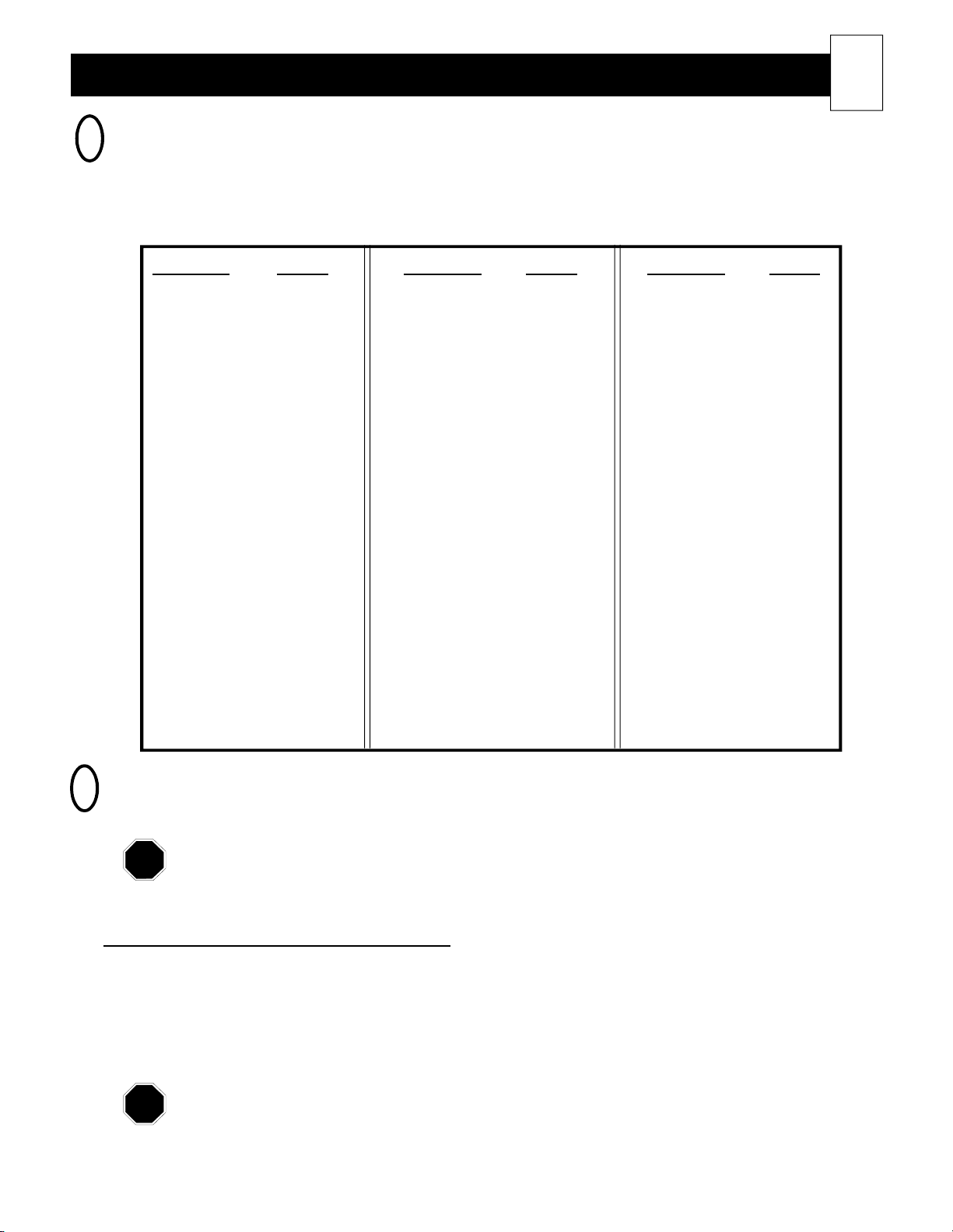
TEMPERATURE CONVERSION CHART
2
The room temperature display can be set to read in Celsius or Fahrenheit. All other heater functions relating to
temperature will be reflected in Fahrenheit only. Use this conversion chart to equate the Fahrenheit reading to
Celsius, if desired.
27
Fahrenheit Celsius
-40 -40.0
-30 -34.4
-20 -28.9
-10 -23.3
0 -17.8
5 -15.0
10 -12.2
15 -9.4
20 -6.7
25 -3.9
30 -1.1
32 0.0
35 1.7
40 4.4
45 7.2
50 10.0
55 12.8
60 15.6
61 16.1
62 16.7
63 17.2
64 17.8
Fahrenheit Celsius
65 18.3
66 18.9
67 19.4
68 20.0
69 20.6
70 21.1
71 21.7
72 22.2
73 22.8
74 23.3
75 23.9
76 24.4
77 25.0
78 25.6
79 26.1
80 26.7
81 27.2
82 27.8
83 28.3
84 28.9
85 29.4
86 30.0
Fahrenheit Celsius
87 30.6
88 31.1
89 31.7
90 32.2
91 32.8
92 33.3
93 33.9
94 34.4
95 35.0
96 35.6
97 36.1
98 36.7
99 37.2
100 37.8
200 93.3
400 204.4
600 315.6
800 426.7
1000 537.8
1200 648.9
1400 760.0
1600 871.1
1800 982.2
DESCRIBING THE HEATER FUNCTIONS (L00 through L10)
3
All heater functions relating to temperature will be reflected in Fahrenheit, even if the room
temperature display is set to read in Celsius. The Celsius equivalency to Fahrenheit is listed next
to these temperature function descriptions for your reference. For a complete list of temperature
conversions, refer to the Temperature Conversion Chart, Table 5, in this manual.
Location 0 (L00) - Room Temperature Set Point
This is the room temperature set point. This set point typically is not adjusted in this location but rather
in the standard edit mode. The maximum value of this set point is dictated by the value in Location 8
(L08), and the minimum value is dictated by the value in Location 9 (L09).
Data Value Range: d00 to d99 (degrees Fahrenheit)
(Celsius equivalency: -17.8 to 37.2)
Refer to Adjusting the Room Temperature Set Point section of this manual for more information.
Page 29
28
NOTE
NOTE
Location 1 (L01) - Brick Core Temperature Set Point
Advanced Heater Operation (cont'd)
If Using Automatic Charge Control: The data entered into this location provides a trim adjustment to
brick core temperature. As the heater charges automatically in relation to outdoor temperature, this
trim will either increase (up by +25%) or decrease (down by -25%) brick core temperature. If you do
not desire to use the trim function, this should be set at d05. L01 is factory preset at d05.
Data Value Range: d00 to d10
If Using Manual Charge Control: The data entered in this location indicates the targeted brick core
charge level for the room heating unit. It is factory preset at d05 (approximately 50% core charge).
Data Value Range: d00 to d10
d00 = -25% trim
d10 = +25% trim
d00 = no core charging will occur
d05 = 50% core charge will be maintained
d10 = maximum core charge will be maintained
Refer to Adjusting the Brick Core Charging Level section in this manual for more
information.
Location 2 (L02)
Presently, this location is not used. L02 is factory preset at d01 and should not be changed.
Location 3 (L03) - Display Illumination
This location is used to set the face plate's illumination status. Usually, the face plate is preset for
continuous display of current room temperature. This can be changed so the face plate display goes
blank after a few seconds of inactivity. L03 is factory preset at d00.
Data Value Range: d00 to d04
d00 = continuous illumination of the face plate
d01 = display goes blank after a period of inactivity (less than
one minute)
d02, d03, d04 = currently, no function associated with these
values
Location 4 (L04) - Automatic Charge Control Start Charging Set Point
This location indicates the outdoor temperature at which the room heating unit should start brick core
charging. L04 is factory preset at d60 (60oF which equates to 15.6oC).
Data Value Range: any value up to d90 (degrees Fahrenheit)
Only applicable if using Automatic Charge Control. Refer to Adjusting the Brick
Core Charging Level section of this manual for more information.
Page 30
Advanced Heater Operation (cont'd)
NOTE
NOTE
NOTE
Location 5 (L05) - Automatic Charge Control Full Charge Set Point
This location indicates the outdoor temperature where the room heating unit should have a full brick
core charge. Example: If Location 4 (L04) has a value of d60 and Location 5 (L05) has a value of
d20, the room heating unit will take a proportional charge at any outdoor temperature between these
two set points. L05 is factory preset at d20 (20oF which equates to -6.7oC).
Data Value Range: any value up to d90 (degrees Fahrenheit)
Only applicable if using Automatic Charge Control. If you are entering a negative
data value into a location, the face plate will display a "-" (minus sign) rather than a
"d" while in the edit mode. Refer to Adjusting the Brick Core Charging Level
section of this manual for more information.
Location 6 (L06) - Room Temperature Set Back
This location indicates the number of degrees (oF) the room temperature set point will be reduced if a
room temperature set back signal is received by the room heating unit. L06 is factory preset at d00.
Data Value Range: d00 to d65
This location should be preset by the installer during the installation procedure if
the room temperature set back function is to be enabled in the application. It is the
factory recommendation that the owner does not adjust this setting once it has been
set.
29
Location 7 (L07) - Display Operation Mode
This location sets the display operation mode for room temperature and brick core temperature. L07 is
factory preset at d00.
Data Value Range: d00 to d04
d00 = will allow for only room temperature setting adjustment
at any time.
d01 = will allow for only room temperature setting adjustment;
however, the M button must first be depressed for a
few seconds
d02 = will allow for room and core temperature settings to be
edited after the M button is depressed for few seconds
d03, d04 = not recommended to be utilized
If using manual charge control, the data in this location should be set to d02.
Location 8 (L08) - Room Temperature - Maximum Value
This location is used to set the maximum room temperature set point. This set point is the highest
temperature to which the room temperature thermostat can be adjusted. For example: If the data value
in this location is set to d85, then 85oF will be the highest room temperature to which the thermostat
can be adjusted. L08 is factory preset at d85 (85oF which equates to 29.4oC).
Data Value Range: d45 to d99 (degrees Fahrenheit)
(Celsius equivalency: 7.2 to 37.2)
Page 31
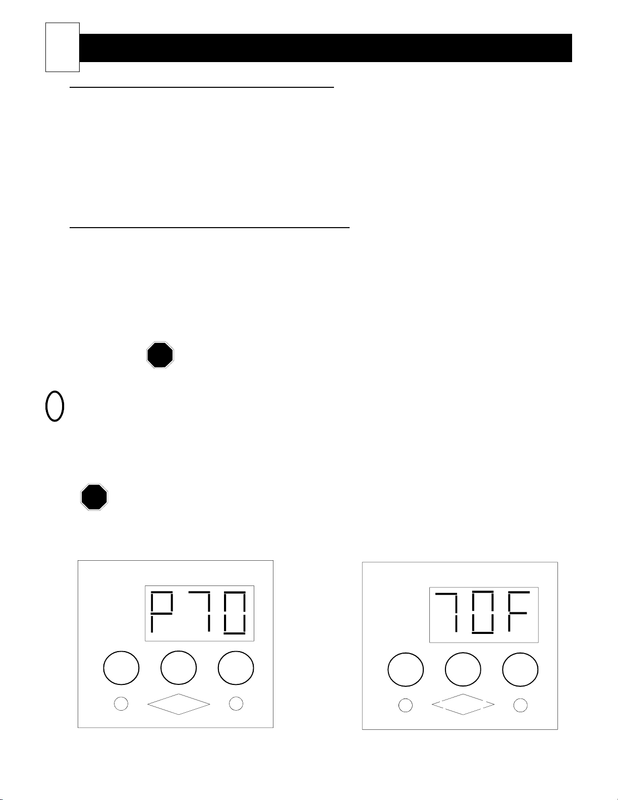
30
NOTE
NOTE
Location 9 (L09) - Room Temperature - Minimum Value
Location 10 (L10) - Room Temperature Display Calibration
Advanced Heater Operation (cont'd)
This location is used to set the minimum room temperature set point. This set point is the lowest
temperature to which the room temperature thermostat can be adjusted. For example: If the data
value in this location is set to d45, then 45oF will be the lowest room temperature to which the thermostat can be adjusted. When adjusting the room temperature set point below this setting, the heater will
be shut off. "OFF" will be displayed on the face plate. L09 is factory preset at d45 (45oF which
equates to 7.2oC).
Data Value Range: d01 to d80 (degrees Fahrenheit)
(Celsius equivalency: -17.2 to 26.7)
This location allows for calibrating of the current room temperature value which is displayed. By
entering a negative number into this location, the actual room temperature value displayed will be
decreased by that number. By entering a positive number, the room temperature value displayed will
be increased by that number. For example: The room heating unit could sense it is 68oF in the room;
however, with a data value of d04 entered into this location, the face plate will display 72oF. Calibration of the room temperature may vary from heater to heater and will be set at the factory.
Data Value Range: -20 to d20 (degrees Fahrenheit)
If you are entering a negative data value into a location, the face plate will display a
"-" (minus sign) rather than a "d" while in the edit mode.
BRICK CORE OPERATING MODES: "C", "P", AND "A"
4
Typically, the face plate of the control panel will continuously display current room temperature. It will also
display a "C" for charge, "P" for peak, or "A" for anticipated peak to indicate the current brick core operating
mode (See Figure 21). The face plate can be set so these brick core charging modes are not displayed; but,
rather, an "F" for Fahrenheit or "C" for Celsius is displayed after the room temperature (See Figure 22.)
These options can be preset to owner preference during the installation procedure when the
heater operational functions are being set. The installing electrical contractor or power company
personnel will have more information on how to change these functions in the heater.
Figure 22
MODE TEMPERATURE
ROOM
SETTING
SERVICE
STORAGE
SETTING
Figure 21
MODE TEMPERATURE
ROOM
SETTING
SERVICE
STORAGE
SETTING
M
STEFFES
Room Temperature and Brick Core Operating Mode Peak Displayed
M
STEFFES
Room Temperature and Fahrenheit Displayed
Page 32
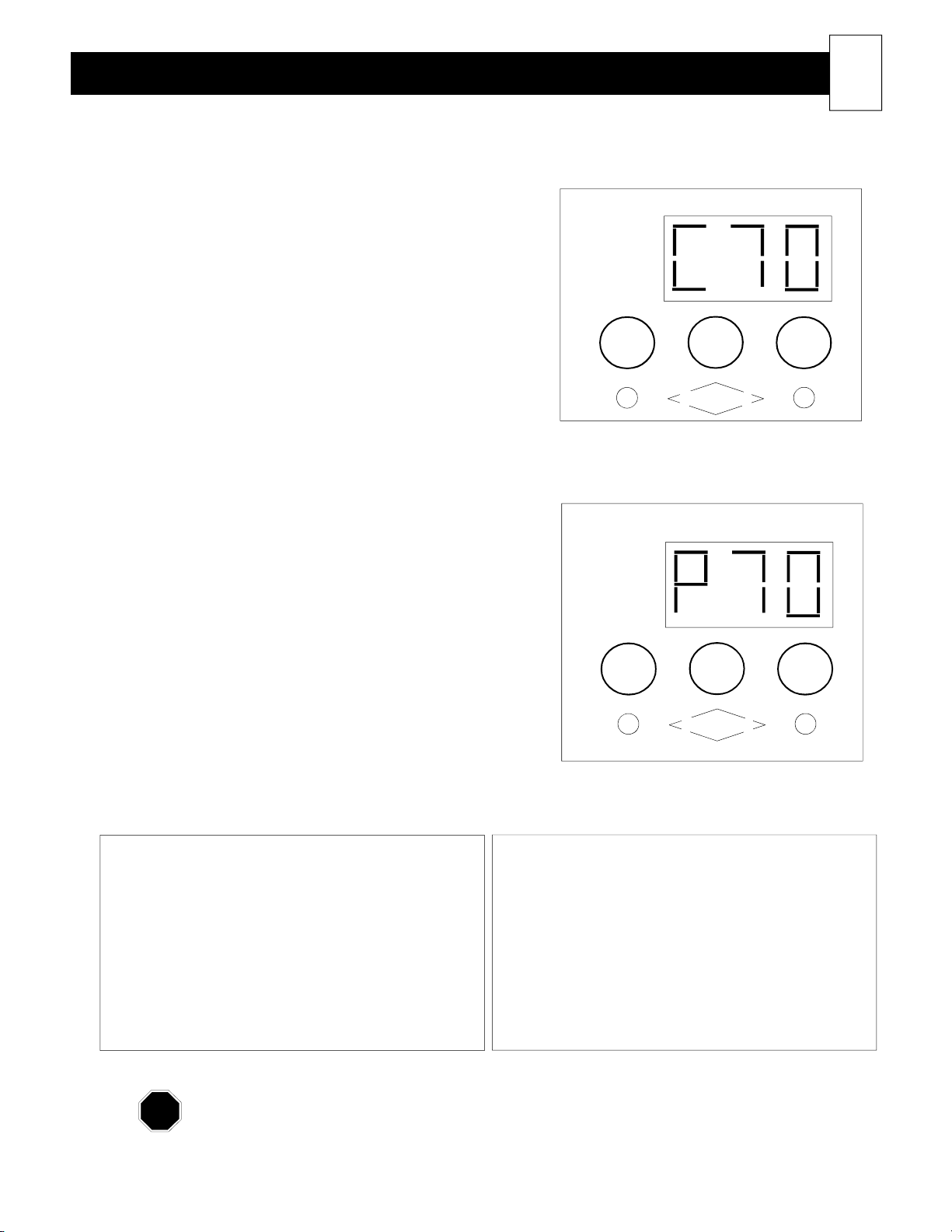
Advanced Heater Operation (cont'd)
NOTE
1. Charge Mode (Off-Peak): See Figure 23
• MODE digit displays a "C".
• TEMPERATURE digits display current room
temperature.
• During this mode, if the temperature of the brick
core is insufficient (based on the manual charge
setting or the automatic charge control outdoor
temperature information), the heating elements will
be on. Heat will be stored in the bricks to maintain
the appropriate charge level. Once the appropriate
brick core charge level is reached, the heating
elements will automatically turn off.
• The blower turns on when the room thermostat
calls for heat and extracts heat from the brick core
to maintain a constant, comfortable room temperature.
• If the room thermostat calls for heat during a time
when there is no heat stored in the brick core, the
blower and heating elements will come on and
begin releasing heat to the area until the heat call
has been satisfied.
2. Peak Mode (On-Peak): See Figure 24
• MODE digit displays a "P".
• TEMPERATURE digits display actual room tem-
perature.
• During this mode, the heater is not allowed to store
heat in the bricks. The heating elements will remain
off for the duration of the on-peak period. (Exception: If the utility company permits the use of the
freeze protection and/or comfort override options,
some element operation may occur. See below.)
• The blower turns on when the room thermostat calls
for heat and extracts heat from the brick core to
maintain a constant, comfortable room temperature.
ROOM
SETTING
SERVICE
STORAGE
SETTING
ROOM
SETTING
SERVICE
STORAGE
SETTING
FIGURE 23
MODE TEMPERATURE
M
STEFFES
Control Panel Display
FIGURE 24
MODE TEMPERATURE
M
STEFFES
Control Panel Display
31
Comfort Override (power company permitting)
This feature is used to achieve room comfort in the
area where the heater is located if the stored heat in
the brick core has been depleted. If the power
company permits the use of this feature, it will allow
the heating elements to come on during a peak mode.
This occurs only if the room temperature falls a
preset number of degrees below the room temperature
set point and the stored heat in the brick core has been
depleted.
Freeze protection and peak override options may not be available in your area. Please consult
your power company if you are unsure of whether these options are available to you.
Freeze Protection (power company permitting)
This feature is used to maintain a temperature above
freezing in the area where the heater is located. If
the power company permits the use of this feature, it
will allow the heating elements to come on during a
peak mode. This occurs only if room temperature
falls below the freeze protection temperature set
point as programmed in the heater.
Page 33
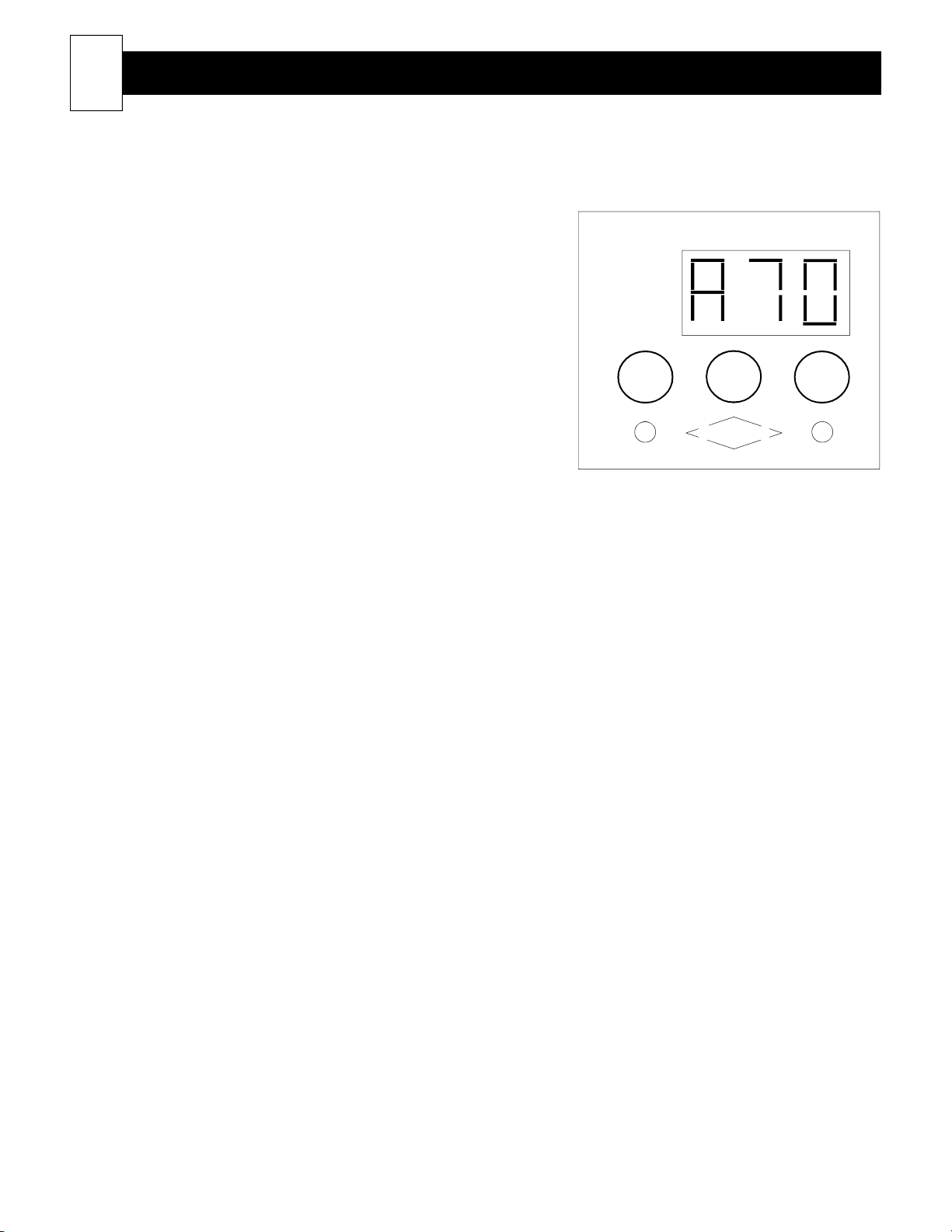
32
3. Anticipated Peak (Pre-Peak) Mode: See Figure 25
Advanced Heater Operation (cont'd)
This mode is used only in specialiazed installations.
You may not have this option enabled on your
heating unit.
FIGURE 25
This mode of operation is used in situations where the
power company sends a signal to the equipment prior
to the possibility of a control (on-peak) period. Once
the signal is received, the room heating unit will charge
to a level needed to satisfy the heating requirements of
the area during the control period.
• MODE digit displays an "A".
• TEMPERATURE digits display actual room
temperature.
• During this mode, the heater is allowed to store heat
in the brick core. If the brick core charge level is
insufficient (based on the manual charge setting or
the automatic charge control outdoor temperature
information), the heating elements will be on. Heat
will be stored in the bricks to maintain the appropriate charge level. Once the appropriate brick core
charge level is reached, the heating elements will
automatically turn off.
• The heater can be set so that the blower comes on as the room thermostat calls for heat, or it can be
set so that it cannot come on at all during an anticipated peak period. The heater can also be set so
that there is limited blower operation during this time. Under some situations, limiting the amount
of blower operation, or not allowing it to come on at all, may be necessary to ensure that the room
heating unit will have an adequate amount of heat stored in the bricks for an upcoming peak control
period.
ROOM
SETTING
SERVICE
STORAGE
SETTING
MODE TEMPERATURE
M
STEFFES
Control Panel Display
Page 34

Customer Notes
Please record your model and serial number below. This information is located on
the lower left side panel of the heater. Retain this information for future reference.
Model Number __________________________________________________________
Serial Number __________________________________________________________
Date Purchased _________________________________________________________
Purchased From ________________________________________________________
Date Installed___________________________________________________________
Installed By ____________________________________________________________
33
Notes:
______________________________________________________________________
______________________________________________________________________
______________________________________________________________________
______________________________________________________________________
______________________________________________________________________
______________________________________________________________________
______________________________________________________________________
______________________________________________________________________
______________________________________________________________________
______________________________________________________________________
REMINDER: Please remember to fill out your Warranty Registration Card
and mail it in as soon as possible. Thank you!
Page 35
NOTE
34
Registering your purchase is an essential step to ensure warranty coverage. A Warranty Registration card is
included with the Owner's Manual. Simply complete, detach the bottom portion, and return the card today.
Retain the top portion of the card for your files.
Your Steffes product is protected by one of the most comprehensive warranties and outstanding service networks
in the industry. We welcome comments you have relating to the equipment. Enjoy your new purchase!
Steffes Corporation (“Steffes”) warrants that the Steffes Electric Thermal Storage Heating Appliance is
free from defects in materials and workmanship under normal use and service. Steffes’ obligation under this
Warranty is limited to the repair or replacement of the appliance or parts only which prove to be defective under
normal use within five (5) years of the date of installation and which Steffes’ examination of the returned
appliance or part(s) shall verify to Steffes’ satisfaction that it is defective. The user shall be responsible for any
labor costs associated with the repair or replacement of the appliance or part(s), including the cost of returning
the defective appliance or part(s) to Steffes Corporation.
This Warranty is void if the heating appliance is moved from the premises in which it was originally
installed. This Warranty shall not apply to an appliance or part which has been altered in any respect, or
improperly installed, serviced or used, or has been subject to accident, negligence, abuse or misuse.
THE ABOVE WARRANTY BY STEFFES IS EXCLUSIVE AND IN LIEU OF ALL OTHER
WARRANTIES, WHETHER WRITTEN OR ORAL, EXPRESS OR IMPLIED, INCLUDING
ANY IMPLIED WARRANTY OF MERCHANTABILITY OR OF FITNESS FOR A PARTICULAR PURPOSE.
The user assumes all risk and liability whatsoever resulting from the use of this heating appliance. In no
event shall Steffes be liable for any indirect, special or consequential damages or lost profits.
This Limited Warranty contains the complete and exclusive statement of Steffes’ obligations with respect
to the heating appliance and any parts thereof. The provisions hereof may not be modified in any respect except
in writing signed by a duly authorized officer of Steffes.
Warranty
The equipment described herein is intended for installation in accordance with applicable local, state and
national electrical codes and must be installed by a qualified electrician.
This manual should be retained by owner upon completion of the installation and made available to
service personnel as required.
3050 Hwy 22 North • Dickinson, ND 58601-9413• 701-483-5400
DOCUMENT #1200048
 Loading...