

Page 1

Solarix MPPT 3020 / MPPT 5020
Installation and operating instructions
EN
764393 | Z01 | 18.43
Page 2

EN
Preface
Thank you for choosing a solar charge controller from our company. Through the use of
solar energy, you significantly help to protect the environment by reducing the pollution of
the atmosphere by the emissions of carbon dioxide (CO
All rights reserved, including those for the translation. No part of this manual may be reproduced in any form without our written consent, nor processed by means of electronic systems.
) and other harmful gases.
2
2
Page 3

EN
Table of contents
1 General information .................................................................... 4
2 Safety instructions ...................................................................... 5
2.1 Labels and symbols .............................................................................................. 6
2.1.1 Safety marks ......................................................................................................... 6
2.1.2 Keywords .............................................................................................................. 6
3 Designated use ............................................................................ 7
4 Overview ...................................................................................... 8
5 Installation ................................................................................... 9
6 Operation ................................................................................... 13
6.1 Switching on / switching off ................................................................................. 15
6.2 Changing the display: ......................................................................................... 16
6.3 Settings menu ..................................................................................................... 18
7 Maintenance and care ............................................................... 26
8 Disposal ..................................................................................... 26
9 Fault correction ......................................................................... 27
9.1 Measures in the event of faults ........................................................................... 28
10 Technical data ........................................................................... 30
11 Commercial and legal guarantee conditions .......................... 32
3
Page 4

EN
1 General information
The solar charge controller is available in two power levels (30 A and 50 A).
The device fulfils the following tasks:
• Optimizing the power yield of the connected solar modules
• Controlling the charging process of the battery
• Monitoring the charge state of the battery
• Connecting and disconnecting the consumers connected to the load output
Characteristics
• Intelligent Maximum Power Point Tracking
• Automatic battery voltage detection
• Three-stage charging process to optimize battery performance
• Maximum efficiency up to 99 %
• Charging current configurable depending on the application
• Support of various battery types
• Backlight
• Data output via serial interface (RS-232)
The state-of-the-art device is equipped with an optimized "Maximum Power Point Tracking
(MPPT)" algorithm and is, thus, able to utilise the maximum available power of the solar
module at any point in time and in a wide range of environmental conditions.
The type plate with the required data related to the device and the manufacturer is attached on the bottom of the right side.
The declaration of conformity is available on the website of the manufacturer.
Scope of delivery
• 1 ea. solar charge controller
• 1 ea. installation and operating instructions
Prior to the installation, check whether the packaging and the device are intact.
4
Page 5

EN
2 Safety instructions
This document is part of the product.
• Read these operating instructions thoroughly and completely prior to installation and
use.
• Keep these operating instructions close the device over the entire lifetime of the device.
• Pass these operating instructions on to every subsequent owner or user of the product.
The installation may only be carried out by a qualified trained electrician.
The solar module and the battery supply voltage to the device even while the device is
switched off. When connecting or disconnecting the solar module or the battery, proceed
precisely as described in the instructions in chapter 5.
Incorrectly connected components can damage the device.
Improper operation can reduce the yields of the solar energy system.
System components can be damaged as well.
If one of the following components is damaged, immediately take the device out of operation and disconnect it from battery and solar module:
• Device (not functioning, visible damage, smoke, penetration of liquid etc.)
• Terminals and connected cables
• Solar module
Do not switch the device on again before it has not been repaired by the dealer or manufacturer, or the damaged cables or solar modules have not been repaired by a specialist.
Do not cover the device.
Follow the following instructions to prevent any risk of fire and explosion:
• Do not use the solar charge controller in a dusty environment, in the proximity of solvents, or where flammable gases and vapours may arise.
• Avoid open fire and light in proximity of the batteries. Avoid sparking.
• Ensure that the room is adequately ventilated.
• Check the charging process regularly.
• Follow the charging instructions of the battery manufacturer.
Do not open the case: There is danger to life! Opening the case will also void any warranty.
Have the device only repaired by a qualified specialist workshop or the manufacturer.
Do not change, remove, nor render illegible the signs and markings attached by the manufacturer.
If connecting an external device that is not described within this document, follow the manufacturer’s instructions. Incorrectly connected devices may cause damage to the solar
charge controller.
5
Page 6
EN
Keyword
Meaning
Do not allow the following persons to operate the device:
• Children
• Persons with reduced physical, sensory or mental capabilities
• Persons that do not possess sufficient experience and knowledge (unless given instruc-
tion on proper use of the device and initial supervision by a person responsible for their
safety)
Follow the safety instructions of the connected battery. The charging voltages and currents
must be set on the solar charge controller in accordance with the battery documentation.
The manufacturer disclaims all responsibility for damages due to solar charge controller
parameters set incorrectly.
Follow the safety instructions of the connected solar module.
Follow the general and national safety and accident prevention regulations.
2.1 Labels and symbols
2.1.1 Safety marks
The following safety marks are used on the device and in these instructions:
Warning sign Nature of the danger
Warning of hazardous voltage
Warning of hazardous area
Follow the instructions
2.1.2 Keywords
The following keywords are used in these instructions:
DANGER
WARNING
NOTE
6
Indicates a hazardous situation which, if not avoided, leads to death or
serious injuries.
Indicates a potentially hazardous situation which, if not avoided, may
lead to death or serious injuries.
Indicates a potentially hazardous situation which, if not avoided, may
lead to damage to property and/or the environment.
Page 7

EN
3 Designated use
The solar charge controller is suitable for photovoltaic (PV) systems, for charging batteries
of a rated voltage of 12 VDC or 24 VDC (50 A version also 48 VDC).
The areas of use include the fields of hobbies and leisure, businesses, commerce, and
small companies.
Installation, putting into operation, and removal of the device may only be carried out by
trained qualified personnel complying with the applicable on-site installation regulations.
The qualified personnel must be acquainted with these operating instructions and follow
the instructions.
The end customer may only carry out the operating functions.
The solar charge controller works with direct current and may not be connected to the
public alternating current grid.
Operation is only allowed indoors.
The solar charge controller is only suitable for controlling solar modules. Do not connect
any other charging sources to the solar charge controller. Otherwise, the solar charge controller and/or the source may be destroyed.
The connected solar modules and batteries must satisfy the stated specifications (refer to
chapter 10).
The solar charge controller is basically suitable for the following types of rechargeable
batteries:
• Lead accumulators with liquid electrolyte
• Sealed lead accumulators; AGM, GEL
• Lithium-ion batteries
NOTE
The operator must ensure that the solar charge controller's settings match
the specifications on the battery's data sheet.
Only lithium-ion batteries may be applied that are equipped with an integrated BMS (Battery Management System) and a safety protective shutdown of the battery in the event of a fault provided that no communication
with the BMS is required.
The respective battery type must be set on the solar charge controller, refer to chapter 6.
The default setting is lead battery GEL/AGM.
Other battery types can be configured. An erroneous configuration may damage the solar
charge controller or the battery. The use of the program function is at the operator's own
responsibility.
7
Page 8
EN
1 Display (LCD)
4 Electrical connections
Disclaimer
Both the compliance with these instructions and the conditions and methods during installation, operation, use, and maintenance of the solar charge controller cannot be supervised
by the manufacturer. Improper performance of the installation may cause property
damages and, subsequently, endanger persons.
Therefore, we assume no responsibility and liability for losses, damages or costs that result
due to incorrect installation, improper operation, usage, and maintenance or in any manner
associated therewith.
We also do not assume any responsibility for infringements of patent rights or infringements of other third-party rights resulting from the use of this solar charge controller.
The manufacturer reserves the right to carry out modifications to the product, technical
data, or installation and operating instructions without prior notice.
Attention: Opening the device, any manipulation and repair attempts, as well as any use
not in accordance with the intended use result in the loss of warranty.
4 Overview
Two versions for different charging currents are available:
• Solar charge controller 30 A
• Solar charge controller 50 A
2 LEDs
3 Buttons
5 Communication interface (for accessories)
6 Earth connection
8
Page 9
EN
Under solar radiation, the solar modules and cables may be energised. There
The solar charge controller optimizes the charging of the battery and its lifetime by means
of a three-stage charging algorithm and a configurable equalizing charge:
Charging stages Description
Bulk charge stage
The battery is charged with the maximum power possible
depending on the input by the solar modules
Absorption stage
Battery charging at a constant voltage. The duration of the
absorption charge is configurable.
Float stage
Trickle charging at a constant voltage. If the battery voltage
drops below the threshold voltage for the float charge, a
switch to bulk charge is performed.
Equalize stage
The equalizing charge regenerates the battery to keep the
capacity loss over the lifetime as low as possible.
The equalizing charge function is controlled via the settings
in the programs 07, 08, 09, 10, 11, 12, and 13. To use the
function, it must have been activated in program 07.
Accessories (not included):
PA WiFi1: WiFi box to link the solar charge controller up with a web portal.
5 Installation
DANGER
Voltage
is the risk of injuries and fire due electrocution and electric discharge.
►
Disconnect the connections from the power sources prior to any work on
the device.
►
Only have specialists carry out any installation work.
►
Only connect the cables to the solar charge controller when it is requested
by the instructions.
9
Page 10
EN
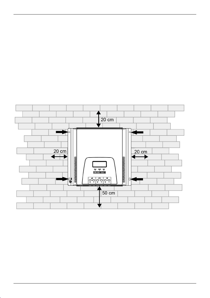
Mounting location:
• Mount only indoors.
• Mount in vertical position on the wall, on concrete or another non-flammable surface.
Mounting materials such as screws and dowels depend on the mounting surface and
are, therefore, not included in the scope of delivery.
• Observe the free space specified below to ensure ventilation of the device.
• Observe the ambient temperature and air humidity specified in the technical data (refer
to chapter 10).
• To allow a clear view of the display, mount the device at about eye level.
• Select mounting location such that the lengths of the cables to the solar module, the
battery, and the consumer are kept as short as possible.
Mounting location with free space for ventilation
1. Place the device in mounting position.
2. Mark the position of the mounting bores through the four fixing holes on the device
frame.
3. Drill the four mounting bores in the mounting surface (Ø 5 mm).
4. Fix the device with fixing materials suitable for the type of mounting surface.
10
Page 11

EN
Device
System
Core cross-section
Tightening
Battery
Electrical connection
The connections to the solar modules must be realised with circuit breakers or disconnectors. The connections to the batteries must be realised with a fuse or a circuit breaker. It is
not allowed to connect inverters to the load output.
Recommended core cross-sections, tightening torques, and battery circuit breakers:
version
voltage
torque
circuit breaker
Battery: 16 mm²
12 V
Solar module: 16 mm²
Load: 16 mm²
30 A
1.2 Nm 40 A
Battery: 6 mm²
24 V
Solar module: 6 mm²
Load: 6 mm²
Battery: 16 mm²
12 V
Solar module: 25 mm²
Load: 16 mm²
Battery: 6 mm²
50 A
Solar module: 6 mm²
2 Nm 60 A 24 V
Load: 6 mm²
Battery: 6 mm²
48 V
Solar module: 6 mm²
Load: 2.5 mm²
The recommended core cross-sections apply to the following presumed distances to the
device:
• 2 m to the battery
• 10 m to the solar module
• 5 m to the load
In the case of considerably different distances, the core cross-sections must be adapted.
The following solar module voltages are assumed:
• 30 V for 12 V system voltage
• 60 V for 24 V system voltage
• 90 V for 48 V system voltage
11
Page 12

EN
The tightening torques apply to the terminal screws of all electrical connections on the device. The values specified for the battery circuit breaker are calculated maximum values.
This means that the battery circuit breaker used must trigger no later than when reaching
this amperage.
It is recommended to use a two-pole circuit breaker between solar module and solar
charge controller.
In this way, the solar modules can be connected to or disconnected from the solar charge
controller without voltage, and no electric arcs will form at the terminals.
NOTE
If the solar module is connected to the battery connections, the solar charge
controller may be damaged.
Connect the cables correctly.
Ensure correct polarity by measurement of voltage on the cables prior to connection.
Observe the connection order described below to ensure correct operation of
the solar charge controller.
Proceed in inverse order for uninstalling.
1. Ensure that all cables to the solar charge controller are without voltage due to the
open isolating device (solar module circuit breaker or battery fuse).
2. Strip all cables on the connection side and provide with ferrules if necessary:
- 30 A version: 10 mm
- 50 A version: 18 mm
12
Page 13

EN
No more than one of the negative terminals or one of the positive terminals of
may be connected to earth.
3. Successively introduce the conductors into the screw-type terminals of the solar
charge controller and tighten the terminal screws.
4. Connect positive cable (+) of the battery to the battery positive input of the solar
charge controller.
5. Connect negative cable (-) of the battery to the battery negative input of the solar
charge controller.
6. Connect positive cable (+) of the solar module to the solar module positive input of the
solar charge controller.
7. Connect negative cable (-) of the solar module to the solar module negative input of
the solar charge controller.
8. Connect positive cable (+) of the consumer to the consumers circuit positive input of
the solar charge controller.
9. Connect negative cable (-) of the consumer to the consumers circuit negative input of
the solar charge controller.
10. Connect earth cable (at least AWG 8/10 mm²) to the earth connection of the solar
charge controller.
NOTE
the connections of the solar modules, of the battery, or of the load output
6 Operation
NOTE
A battery must have been connected prior to switching on. The solar charge
controller does not work if a solar module but no battery is connected.
The operating panel consists of the display, three LEDs and three buttons:
1 Display
2 LEDs
13
3 "Load on/off & ESC" button
4 "Enter & Call settings menu" button
5 "Up/down & On/off" button
Page 14

EN
LED
Colour
Status
Meaning
Button
Function
Meaning
Symbol
Meaning
Meaning of the LEDs:
SOLAR Green
Permanently lit Input Solar module normal
Off
Input Solar module without voltage or
defective
CHARGE Green
FAULT Red
Function of the buttons:
Up/down &
On/off
Enter &
Call settings menu
Load on/off & ESC
Symbols on the display:
Permanently lit Battery is fully charged
Flashing Battery is being charged
Flashing Error
Off
Selecting next visualization
Switching solar charge controller on and off if there is
no input from the solar module present
Confirming selection in the program mode
Going to program mode or jumping to main page
Acknowledging errors
Switching load circuit on and off manually
Leaving settings menu
Solar charge controller is working
normally
Display mode Program entry
Day/night indicator
The moon symbol is shown while there is no input coming from the
solar module
Indicates current flow
14
Page 15

Symbol
Meaning
Battery
Consumer
Normal operation / fault
Level of battery charge
When all segments are black, the battery is fully charged
Text display / values / unit
Display during program entry and fault
Shows the program numbers
ERROR XX Flashing with the code for warning
Permanently lit with code for fault
EN
6.1 Switching on / switching off
NOTE
The solar charge controller starts automatically when a sufficiently high
voltage from the solar module is present and a battery is connected.
The solar charge controller can also be switched on and off manually
independently of the solar power.
1. Switch fuse to the battery on.
2. Press "Up/down & On/off" button. The main page appears on the display. The main
page alternates between displaying the battery voltage and displaying the charge state
of the battery.
3. Switch on the disconnector to the solar module. If the sun is shining, the solar charge
controller starts charging the battery.
15
Page 16

EN
Display
Meaning
Display
Meaning
Examples for operating states:
Solar modules are working, battery is being
charged
Consumer is switched on
Solar modules are working, battery is being
charged
No consumer is switched on
No input from the solar module
The consumer is operated with battery current
6.2 Changing the display:
Press "Up/down & On/off" button repeatedly. The following information is displayed
successively (the values in the figures are examples):
Battery voltage (main page)
(here: 12.5 V)
Battery charge state
(here: 60 %)
Solar module voltage
(here: 60 V)
16
Page 17

EN
Display
Meaning
Input current from the solar module
(here: 50 A)
Charging current or discharging current (negative),
battery
(here: 30 A)
Load current, consumer
(here: 20 A)
Total input power
(here: 100 Ah)
Total output power
(here: 80 Ah)
Device temperature (internal)
(here: 40 °C)
Operating hours
(here: 3.5 h)
Maximum occurred battery voltage
(here: 14.7 V)
17
Page 18

EN
Display
Meaning
Minimum occurred battery voltage
(here: 10.1 V)
Maximum occurred charging current
(here: 51.0 A)
Minimum occurred discharging current
(= load current)
(here: 20.8 A)
Firmware version
(here: 1.00)
Then, the main page is displayed again.
6.3 Settings menu
1. Press "Enter & Call settings menu" button and hold for 3 seconds. The solar charge
controller switches to the display mode Settings menu.
If no entry is made during approx. 20 seconds, the display returns to the main page.
2. Press "Up/down & On/off" button repeatedly to select a program. The currently
selected menu item is flashing.
3. Press "Enter & Call settings menu" button to go to the selected program.
4. Press "Up/down & On/off" button to select the desired setting value (the displayed
value is flashing).
5. Press "Enter & Call settings menu" button to confirm the desired value (the displayed
value is no longer flashing).
Alternatively, press "Load on/off & ESC" button to not accept the value and return to
the settings menu.
6. Press "Load on/off & ESC" button to return to the settings menu.
18
Page 19
EN
Program selection
Name
Option
Meaning
01
02
Setting battery
voltage
Selection of
battery type
AUT
12.0 Setting battery voltage 12 V
24.0 Setting battery voltage 24 V
48.0
GEL
FLD Lead-acid battery (standard)
LIO Lithium-ion battery
The battery voltage is detected
automatically
Setting battery voltage 48 V
(only for 50 A version)
Lead battery GEL/AGM
(standard)
The voltage values are
automatically set for this battery
type
Programs 04 and 06 cannot be
used when this setting is
selected
The voltage values are
automatically set for this battery
type
Programs 04 and 06 cannot be
used when this setting is
selected.
When this setting is selected,
programs 04 and 06 must be
adapted
USE User-defined values
When this setting is selected,
programs 04 and 06 must be
adapted
Maximum
charging current
50 A
03
30 A
19
Only for the 50 A version:
Maximum charging current 50 A,
can be set from 5 A to 50 A in
increments of 5 A
Only for the 30 A version:
Maximum charging current 30 A,
can be set from 5 A to 30 A in
increments of 5 A
Page 20
EN
Program selection
Name
Option
Meaning
04
05
06
Voltage of the
absorption
charge
Duration of the
absorption
charge
Voltage for float
charge
If "USE" has been selected in program 01,
this program can be used
14.4 V
28.8 V
57.6 V
If "LIO" has been selected in program 01,
this program can be used
28.8 V
57.6 V
120
If "USE" has been selected in program 01,
this program can be used
14.1 V
12 V rated voltage:
Can be set from 12.0 V to 16.0 V
(default setting: 14.4 V)
24 V rated voltage:
Can be set from 24.0 V to 32.0 V
(default setting: 28.8 V)
48 V rated voltage:
Can be set from 48.0 V to 64.0 V
(default setting: 57.6 V)
30 A version:
Can be set from 9.0 V to 32.0 V
50 A version:
Can be set from 9.0 V to 64.0 V
Can be set from 10 min to
900 min in increments of 5 min
(default setting: 120 min)
12 V rated voltage:
Can be set from 12.0 V to 16.0 V
(default setting: 14.1 V)
28.2 V
56.4 V
If "LIO" has been selected in program 01,
this program can be used
28.2 V
56.4 V
20
24 V rated voltage:
Can be set from 24.0 V to 32.0 V
(default setting: 28.2 V)
48 V rated voltage:
Can be set from 48.0 V to 64.0 V
(default setting: 56.4 V)
30 A version:
Can be set from 9.0 V to 32.0 V
50 A version:
Can be set from 9.0 V to 32.0 V
Page 21

EN
Program selection
Name
Option
Meaning
07
08
09
Equalizing charge
function
Voltage for
equalizing charge
Charging current
for equalizing
charge
EQE
EQD
If "USE" has been selected in program 01,
this program can be used
15.0 V
30.0 V
60.0 V
If "LIO" has been selected in program 01,
this program can be used
30.0 V
60.0 V
50 A
Activating equalizing charge
function
Deactivating equalizing charge
function
12 V rated voltage:
Can be set from 12.0 V to 16.0 V
(default setting: 14.1 V)
24 V rated voltage:
Can be set from 24.0 V to 32.0 V
(default setting: 28.2 V)
48 V rated voltage:
Can be set from 48.0 V to 64.0 V
(default setting: 56.4 V)
30 A version:
Can be set from 9.0 V to 32.0 V
50 A version:
Can be set from 9.0 V to 64.0 V
Only for the 50 A version:
Maximum charging current 50 A,
can be set from 5 A to 50 A in
increments of 5 A
30 A
Duration of the
equalizing charge
240
10
21
Only for the 30 A version:
Maximum charging current 30 A,
can be set from 5 A to 30 A in
increments of 5 A
Can be set from 5 min to 900 min
in increments of 5 min
(default setting: 240 min)
Page 22
EN
Program selection
Name
Option
Meaning
11
12
13
14
Maximum
duration of the
equalizing charge
in case the
voltage of the
equalizing charge
is not reached
permanently
Interval of the
equalizing charge
Starting/stopping
equalizing charge
Undervoltage for
disconnecting
load current
(under-voltage
cutoff)
300
30d
EEN
EDE
11.5 V
23.0
46.0
Can be set from 5 min to 900 min
in increments of 5 min
(default setting: 300 min)
Can be set from 1 day to 90 days
in increments of 1 day
(default setting: 30 days)
Starting equalizing charge
immediately
Stopping equalizing charge
immediately
12 V rated voltage:
Can be set from 9.0 V to 12.5 V
in increments of 0.1 V
(default setting: 11.5 V)
24 V rated voltage:
Can be set from 18.0 V to 25.0 V
in increments of 0.2 V
(default setting: 23.0 V)
48 V rated voltage:
Can be set from 36.0 V to 50.0 V
in increments of 0.4 V
(default setting: 46.0 V)
Voltage for
switching load
15
22
current on again
after undervoltage cutoff
12.5 V
25.0
50.0
12 V rated voltage:
Can be set from 9.0 V to 12.5 V
in increments of 0.1 V
(default setting: 12.5 V)
24 V rated voltage:
Can be set from 18.0 V to 25.0 V
in increments of 0.2 V
(default setting: 25.0 V)
48 V rated voltage:
Can be set from 36.0 V to 50.0 V
in increments of 0.4 V
(default setting: 50.0 V)
Page 23
EN
Program selection
Name
Option
Meaning
Control of load
output
16
The light function refers to the time of dusk and dawn, called sunset time and sunrise
time. If the detected PV input voltage is lower than the set value in program 19, this is
considered as dusk and the time is recorded as sunset time. If the detected PV input
voltage is 5 V higher than the set value in program 19, this is considered as dawn and
the time is recorded as sunrise time.
Mode for load
control
17
ON On (default setting)
Load output is always switched
on, except in the event of undervoltage cutoff
Switching off by pressing the
"Load on/off & ESC" button for
one second
OFF
LIG
EVN Evening light
Load output is always switched
off
Switching on by pressing the
"Load on/ switching & ESC"
button
Power-on time of the load output
is controlled by the settings in
program 18
If selected, the load output is
switched on after sunset and
remains switched on for the
duration set in program 19
MOR Morning light
If selected, the load output is
switched on before sunrise and
remains switched on for the
duration set in program 19
NIT Night light (standard)
If selected, the load output is
switched on for the entire night,
from the sunset time to the
sunrise time independently of the
setting in program 19
23
Page 24
EN
Program selection
Name
Option
Meaning
18
19
20
21
Power-on
duration for load
output
PV voltage to
define sunrise
and sunset time
Temperature
compensation for
battery voltage
Performance
compensation for
battery voltage
480
15.0
30.0
60.0
4
0
Can be set from 0 min to 480 min
in increments of 5 min
(default setting: 480 min)
Can only be set if "LIG" is set in
program 16
12 V rated voltage:
Can be set from 10 V to 80 V in
increments of 1 V
(default setting: 15.0 V)
24 V rated voltage:
Can be set from 20 V to 80 V in
increments of 1 V
(default setting: 30.0 V)
48 V rated voltage:
Can be set from 40 V to 80 V in
increments of 0.1 V
(default setting: 60.0 V)
Can be set from 0 mV to 10 mV
in increments of 1 mV
(default setting: 4 mV)
Can be set from 0 mV to 30 mV
in increments of 1 mV
(default setting: 0 mV)
The cables between solar charge
controller and battery cause
losses. This value compensates
the losses by shifting the voltage.
If, for example, 10 mV are
specified, the charging end
voltage is increased by 10 mV
per ampere of charging current.
At the same time, this value is
deducted per ampere from the
under-voltage cutoff
(program 14)
24
Page 25
Program selection
Name
Option
Meaning
Display backlight ON Backlight is always switched on
EN
22
23
24
25
26
27
28
Reset to factory
setting
Reset of total
input power
Reset of total
output power
Reset of saved
maximum voltage
of the battery
Reset of saved
minimum voltage
of the battery
Reset of saved
maximum
charging current
of the battery
OFF Backlight is always switched off
AUT
RST -
RST -
RST -
RST -
RST -
RST -
Backlight is switched on when
pressing a button The backlight
will go out after 30 second of
inactivity
Reset of saved
maximum load
29
25
current
RST -
Page 26

EN
Do not dispose of the device in the normal household waste.
7 Maintenance and care
The device is maintenance-free.
DANGER
Voltage.
There is a risk of death by electrocution.
Only clean device with a slightly moist cloth.
The care of the device is limited to the following measures:
• Removing dust
• Cleaning
Remove dust from the cooling fins of the device by using compressed air of a maximum of
2 bar.
Light soiling:
Clean surface of the case with a slightly moist cloth (use clear water).
Heavy soiling:
Clean surface of the case with a slightly moist cloth. In addition, use a cleaning agent without solvents or disinfectants, that does not contain any granular or sharp-edged substances.
Remove any residues of the cleaning agent.
8 Disposal
►
►
Dispose of the device in accordance with the local guidelines for disposal
of electrical equipment.
26
Page 27

EN
Symbol and
Meaning
9 Fault correction
DANGER
Voltage.
In the case of improper repairs, risks for the user and the system may arise.
Any claim to warranty will also be cancelled.
►
Do not open the device fro troubleshooting and do not try to replace components by yourself.
If the device detects faults or impermissible operating states, error codes appear on the
display. The "FAULT" LED is flashing.
You can generally differentiate whether there is a temporary malfunction, e.g. due to overload of the device, or if there is a sustained fault.
In the event of temporary malfunctions, the following symbols and error codes are flashing:
error code
ERROR 01 Solar input power is too high
ERROR 03 Charging current is too high
ERROR 05 Device temperature is too high
ERROR 07 Battery voltage is too low
ERROR 08 Battery voltage is too high
ERROR 09 Overload
In the event of sustained faults, the following symbols and error codes are lit:
Symbol and
Meaning
error code
ERROR 02 Internal memory error
ERROR 04 Internal temperature sensor defective
ERROR 10 Short circuit at the load output
ERROR 26 System or battery voltage not detected
27
Page 28

EN
9.1 Measures in the event of faults
Displayed
error code
01 PV overvoltage Check voltage of the solar modules
02
03
04
05
07
Cause Remedy
The voltage must be lower than 100 V for the
30 A version, and smaller than 150 V for the
50 A version
If the voltage of the solar modules is within the
permitted range, contact the service
Internal memory
error
Charging current
too high
Temperature sensor
defective
Excessive
temperature
Battery voltage too
low
Restart the device
If the problem persists, contact the service
Restart the device
If the problem persists, contact the service
Restart the device
If the problem persists, contact the service
Switch device off and restart after some time
If the problem persists, contact the service
Measure battery voltage and check setting in
program 01:
- If a 12 V battery is connected, "AUT" or 12.0 V
must be set in program 01
- If a 24 V battery is connected, "AUT" or 24.0 V
must be set in program 01
Compare the measured value for the battery
voltage and the display on the device. In the
event of discrepancy, contact the service
08
28
Battery voltage too
high
Measure battery voltage and check setting in
program 01:
- If a 24 V battery is connected, "AUT" or 24.0 V
must be set in program 01
- If a 48 V battery is connected, "AUT" or 48.0 V
must be set in program 01 (only applies to the
50 A version)
Compare the measured value for the battery
voltage and the display on the device. In the
event of discrepancy, contact the service
Page 29

Displayed
error code
Cause
Remedy
EN
09
10
26
- No display Press "Up/down & On/off" button
Load output
overloaded
Short circuit at the
load output
System voltage not
detected
Check if the load output is overloaded
Inverters must be connected directly to the
battery, they must not be operated via the load
output
If the load output is overloaded, disconnect
consumers from the load output
If the problem persists, contact the service
Check if a short circuit is present at the load
output
Disconnect consumers from the load output
Eliminate short circuit
If the problem persists, contact the service
Check if the rated voltage of the battery matches
the set value in program 01; adapt value in
program 01 if necessary
Restart the device.
If the problem persists, contact the service
Check battery connection
If the problem persists, contact the service
29
Page 30

EN
10 Technical data
Version 30 A 50 A
Mechanics and surrounding
Dimensions (W x H x D) 230 x 130 x 80 mm 250 x 230 x 85 mm
Weight 1.4 kg 3.2 kg
Ambient temperature
range
Storage temperature -40 °C to 75 °C
Air humidity (relative) 0 % to 90 % RH, non-condensing
Degree of protection IP 20
Electrical system
Rated voltage
Internal consumption ˂ 2 W ˂ 3 W
Max. charging efficiency > 96 % > 98 %
Input, solar modules
Max. voltage of the solar
modules (under all
temperature conditions at
the installation site)
Max. output current, solar
modules
Solar module MPPT
voltage range
12 VDC or 24 VDC
(automatic detection)
100 VOC 150 VOC
30 A (MPP) 50 A (MPP)
12 V: 15 VDC to 80 VDC
24 V: 30 VDC to 80 VDC
0 °C to 55 °C
12 VDC, 24 VDC, or
48 VDC
(automatic detection)
12 V: 15 VDC to 120 VDC
24 V: 30 VDC to 120 VDC
48 V: 60 VDC to 120 VDC
Max. useful charging
power (recommendation:
select maximally 20 %
more than this power as
solar power input)
30
900 W 3000 W
Page 31

Version
30 A
50 A
Battery charging
Max. charging current 30 A 50 A
Required battery capacity Min. 60 Ah Min. 100 Ah
Charging stages 3-stage, plus periodical equalizing charge:
Bulk-Absorption-Float
EN
Charging voltage,
absorption charge (rated
value)
Charging voltage, float
charge (rated value)
Load disconnect in the
event of undervoltage
(rated value)
Switch-on after
undervoltage
Load disconnect in the
event of overvoltage
Switch-on after
overvoltage
Consumers circuit
Max. load current for
consumers
Voltage at the load output Corresponds to the battery voltage
Consumers that require more than 20 A must be connected directly to the battery.
Inverters must not be connected to the load output.
14.4 V / 28.8 V 14.4 V / 28.8 V / 57.6 V
13.9 V / 27.8 V 13.9 V / 27.8 V / 55.6 V
11.5 V / 23.0 V 11.5 V / 23.0 V / 46.0 V
12.5 V / 25.0 V 12.5 V / 25.0 V / 50.0 V
16.5 V / 33.0 V 16.5 V / 33.0 V / 66.0 V
16.0 V / 32.0 V 16.0 V / 32.0 V / 64.0 V
20 A
31
Page 32

EN
11 Commercial and legal guarantee conditions
Find the warranty terms on internet at:
www.steca.com/pv-off-grid/warranties
Steca Elektronik GmbH
Mammostraße 1
87700 Memmingen
Germany
T +49-(0)8331-8558-0
F +49-(0)8331-8558-131
www.steca.de
32
 Loading...