

Steca Solarix MPPT 3020, Solarix MPPT 5020 Installation And Operating Instructions Manual

Solarix MPPT 3020 / MPPT 5020
Installation and operating instructions
EN
764393 | Z01 | 18.43

EN
Preface
Thank you for choosing a solar charge controller from our company. Through the use of
solar energy, you significantly help to protect the environment by reducing the pollution of
the atmosphere by the emissions of carbon dioxide (CO
All rights reserved, including those for the translation. No part of this manual may be reproduced in any form without our written consent, nor processed by means of electronic systems.
) and other harmful gases.
2
2

EN
Table of contents
1 General information .................................................................... 4
2 Safety instructions ...................................................................... 5
2.1 Labels and symbols .............................................................................................. 6
2.1.1 Safety marks ......................................................................................................... 6
2.1.2 Keywords .............................................................................................................. 6
3 Designated use ............................................................................ 7
4 Overview ...................................................................................... 8
5 Installation ................................................................................... 9
6 Operation ................................................................................... 13
6.1 Switching on / switching off ................................................................................. 15
6.2 Changing the display: ......................................................................................... 16
6.3 Settings menu ..................................................................................................... 18
7 Maintenance and care ............................................................... 26
8 Disposal ..................................................................................... 26
9 Fault correction ......................................................................... 27
9.1 Measures in the event of faults ........................................................................... 28
10 Technical data ........................................................................... 30
11 Commercial and legal guarantee conditions .......................... 32
3

EN
1 General information
The solar charge controller is available in two power levels (30 A and 50 A).
The device fulfils the following tasks:
• Optimizing the power yield of the connected solar modules
• Controlling the charging process of the battery
• Monitoring the charge state of the battery
• Connecting and disconnecting the consumers connected to the load output
Characteristics
• Intelligent Maximum Power Point Tracking
• Automatic battery voltage detection
• Three-stage charging process to optimize battery performance
• Maximum efficiency up to 99 %
• Charging current configurable depending on the application
• Support of various battery types
• Backlight
• Data output via serial interface (RS-232)
The state-of-the-art device is equipped with an optimized "Maximum Power Point Tracking
(MPPT)" algorithm and is, thus, able to utilise the maximum available power of the solar
module at any point in time and in a wide range of environmental conditions.
The type plate with the required data related to the device and the manufacturer is attached on the bottom of the right side.
The declaration of conformity is available on the website of the manufacturer.
Scope of delivery
• 1 ea. solar charge controller
• 1 ea. installation and operating instructions
Prior to the installation, check whether the packaging and the device are intact.
4

EN
2 Safety instructions
This document is part of the product.
• Read these operating instructions thoroughly and completely prior to installation and
use.
• Keep these operating instructions close the device over the entire lifetime of the device.
• Pass these operating instructions on to every subsequent owner or user of the product.
The installation may only be carried out by a qualified trained electrician.
The solar module and the battery supply voltage to the device even while the device is
switched off. When connecting or disconnecting the solar module or the battery, proceed
precisely as described in the instructions in chapter 5.
Incorrectly connected components can damage the device.
Improper operation can reduce the yields of the solar energy system.
System components can be damaged as well.
If one of the following components is damaged, immediately take the device out of operation and disconnect it from battery and solar module:
• Device (not functioning, visible damage, smoke, penetration of liquid etc.)
• Terminals and connected cables
• Solar module
Do not switch the device on again before it has not been repaired by the dealer or manufacturer, or the damaged cables or solar modules have not been repaired by a specialist.
Do not cover the device.
Follow the following instructions to prevent any risk of fire and explosion:
• Do not use the solar charge controller in a dusty environment, in the proximity of solvents, or where flammable gases and vapours may arise.
• Avoid open fire and light in proximity of the batteries. Avoid sparking.
• Ensure that the room is adequately ventilated.
• Check the charging process regularly.
• Follow the charging instructions of the battery manufacturer.
Do not open the case: There is danger to life! Opening the case will also void any warranty.
Have the device only repaired by a qualified specialist workshop or the manufacturer.
Do not change, remove, nor render illegible the signs and markings attached by the manufacturer.
If connecting an external device that is not described within this document, follow the manufacturer’s instructions. Incorrectly connected devices may cause damage to the solar
charge controller.
5
EN
Keyword
Meaning
Do not allow the following persons to operate the device:
• Children
• Persons with reduced physical, sensory or mental capabilities
• Persons that do not possess sufficient experience and knowledge (unless given instruc-
tion on proper use of the device and initial supervision by a person responsible for their
safety)
Follow the safety instructions of the connected battery. The charging voltages and currents
must be set on the solar charge controller in accordance with the battery documentation.
The manufacturer disclaims all responsibility for damages due to solar charge controller
parameters set incorrectly.
Follow the safety instructions of the connected solar module.
Follow the general and national safety and accident prevention regulations.
2.1 Labels and symbols
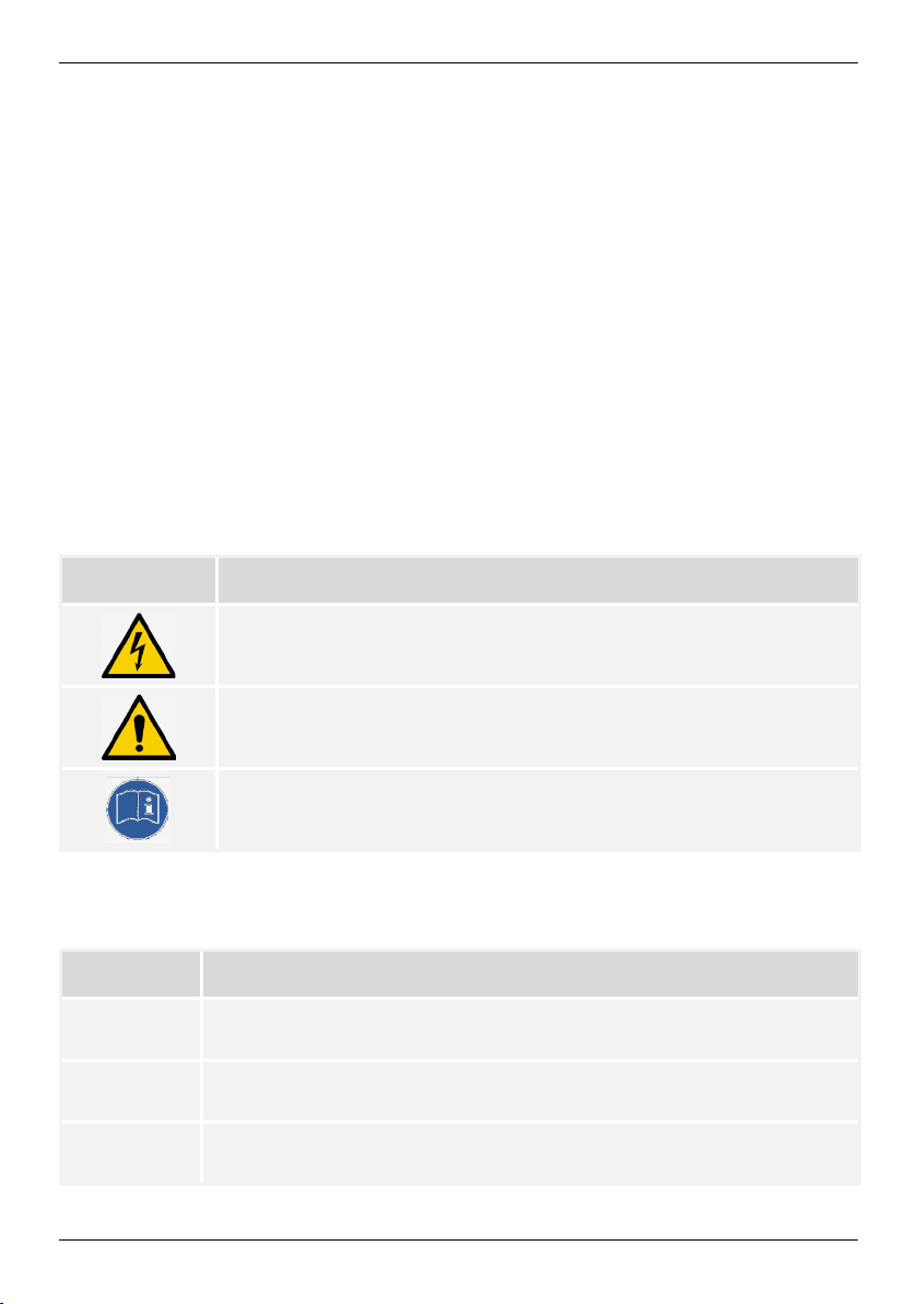
2.1.1 Safety marks
The following safety marks are used on the device and in these instructions:
Warning sign Nature of the danger
Warning of hazardous voltage
Warning of hazardous area
Follow the instructions
2.1.2 Keywords
The following keywords are used in these instructions:
DANGER
WARNING
NOTE
6
Indicates a hazardous situation which, if not avoided, leads to death or
serious injuries.
Indicates a potentially hazardous situation which, if not avoided, may
lead to death or serious injuries.
Indicates a potentially hazardous situation which, if not avoided, may
lead to damage to property and/or the environment.
EN
3 Designated use
The solar charge controller is suitable for photovoltaic (PV) systems, for charging batteries
of a rated voltage of 12 VDC or 24 VDC (50 A version also 48 VDC).
The areas of use include the fields of hobbies and leisure, businesses, commerce, and
small companies.
Installation, putting into operation, and removal of the device may only be carried out by
trained qualified personnel complying with the applicable on-site installation regulations.
The qualified personnel must be acquainted with these operating instructions and follow
the instructions.
The end customer may only carry out the operating functions.
The solar charge controller works with direct current and may not be connected to the
public alternating current grid.
Operation is only allowed indoors.
The solar charge controller is only suitable for controlling solar modules. Do not connect
any other charging sources to the solar charge controller. Otherwise, the solar charge controller and/or the source may be destroyed.
The connected solar modules and batteries must satisfy the stated specifications (refer to
chapter 10).
The solar charge controller is basically suitable for the following types of rechargeable
batteries:
• Lead accumulators with liquid electrolyte
• Sealed lead accumulators; AGM, GEL
• Lithium-ion batteries
NOTE
The operator must ensure that the solar charge controller's settings match
the specifications on the battery's data sheet.
Only lithium-ion batteries may be applied that are equipped with an integrated BMS (Battery Management System) and a safety protective shutdown of the battery in the event of a fault provided that no communication
with the BMS is required.
The respective battery type must be set on the solar charge controller, refer to chapter 6.
The default setting is lead battery GEL/AGM.
Other battery types can be configured. An erroneous configuration may damage the solar
charge controller or the battery. The use of the program function is at the operator's own
responsibility.
7
EN
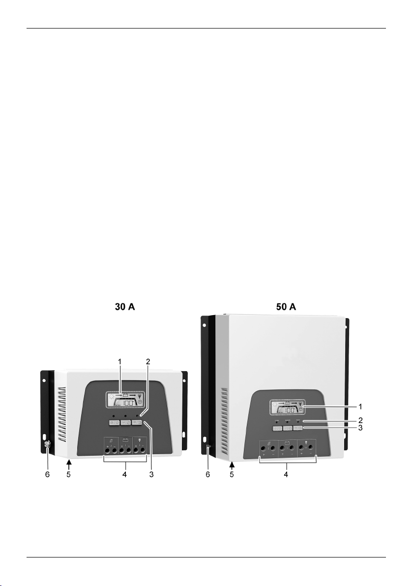
1 Display (LCD)
4 Electrical connections
Disclaimer
Both the compliance with these instructions and the conditions and methods during installation, operation, use, and maintenance of the solar charge controller cannot be supervised
by the manufacturer. Improper performance of the installation may cause property
damages and, subsequently, endanger persons.
Therefore, we assume no responsibility and liability for losses, damages or costs that result
due to incorrect installation, improper operation, usage, and maintenance or in any manner
associated therewith.
We also do not assume any responsibility for infringements of patent rights or infringements of other third-party rights resulting from the use of this solar charge controller.
The manufacturer reserves the right to carry out modifications to the product, technical
data, or installation and operating instructions without prior notice.
Attention: Opening the device, any manipulation and repair attempts, as well as any use
not in accordance with the intended use result in the loss of warranty.
4 Overview
Two versions for different charging currents are available:
• Solar charge controller 30 A
• Solar charge controller 50 A
2 LEDs
3 Buttons
5 Communication interface (for accessories)
6 Earth connection
8
EN
Under solar radiation, the solar modules and cables may be energised. There
The solar charge controller optimizes the charging of the battery and its lifetime by means
of a three-stage charging algorithm and a configurable equalizing charge:
Charging stages Description
Bulk charge stage
The battery is charged with the maximum power possible
depending on the input by the solar modules
Absorption stage
Battery charging at a constant voltage. The duration of the
absorption charge is configurable.
Float stage
Trickle charging at a constant voltage. If the battery voltage
drops below the threshold voltage for the float charge, a
switch to bulk charge is performed.
Equalize stage
The equalizing charge regenerates the battery to keep the
capacity loss over the lifetime as low as possible.
The equalizing charge function is controlled via the settings
in the programs 07, 08, 09, 10, 11, 12, and 13. To use the
function, it must have been activated in program 07.
Accessories (not included):
PA WiFi1: WiFi box to link the solar charge controller up with a web portal.
5 Installation
DANGER
Voltage
is the risk of injuries and fire due electrocution and electric discharge.
►
Disconnect the connections from the power sources prior to any work on
the device.
►
Only have specialists carry out any installation work.
►
Only connect the cables to the solar charge controller when it is requested
by the instructions.
9
EN
Mounting location:
• Mount only indoors.
• Mount in vertical position on the wall, on concrete or another non-flammable surface.
Mounting materials such as screws and dowels depend on the mounting surface and
are, therefore, not included in the scope of delivery.
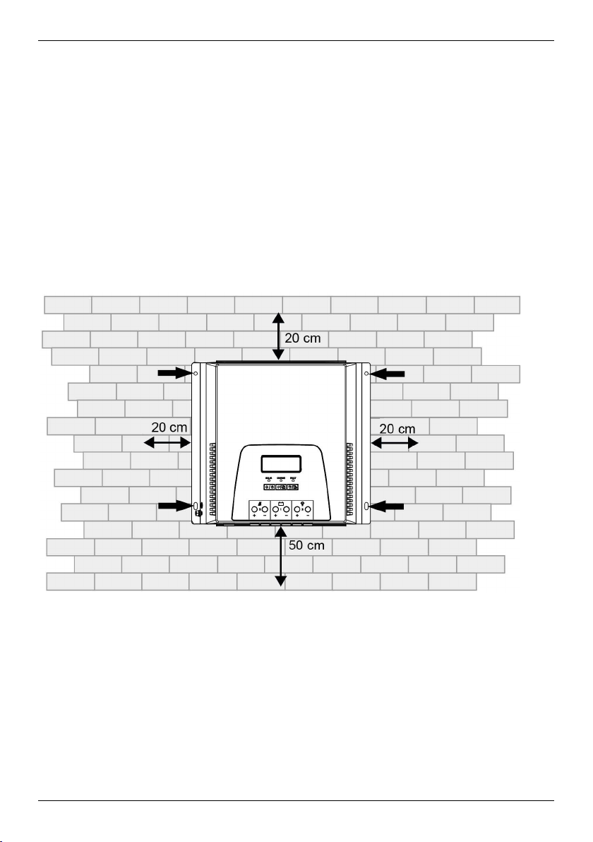
• Observe the free space specified below to ensure ventilation of the device.
• Observe the ambient temperature and air humidity specified in the technical data (refer
to chapter 10).
• To allow a clear view of the display, mount the device at about eye level.
• Select mounting location such that the lengths of the cables to the solar module, the
battery, and the consumer are kept as short as possible.
Mounting location with free space for ventilation
1. Place the device in mounting position.
2. Mark the position of the mounting bores through the four fixing holes on the device
frame.
3. Drill the four mounting bores in the mounting surface (Ø 5 mm).
4. Fix the device with fixing materials suitable for the type of mounting surface.
10
 Loading...