

Steca 746785, Solarix PI 500-12, Solarix PI 500-60, Solarix PI 500-L60, PI 550-24 Installation and operating instructions
...Page 1
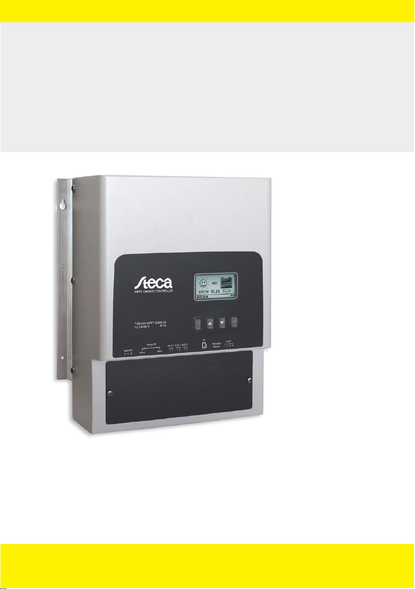
Solar charge controller
Installation and User Instructions
Tarom MPPT 6000-M
Tarom MPPT 6000-S
EN
756.404 | Z01 | 16.06
For further languages please visit: www.stecasolar.com
Page 2

Table of contents
1 General information............................................................................................................. 6
1.1 General safety instructions............................................................................................ 6
1.2 Identification................................................................................................................. 6
1.3 Scope of delivery........................................................................................................... 7
1.4 Proper usage................................................................................................................. 7
1.5 Markings....................................................................................................................... 8
1.5.1 Symbols for warnings and notices.............................................................................. 8
1.5.2 Keywords.................................................................................................................... 9
1.5.3 Terms and abbreviations used.................................................................................... 9
2 Quick guide......................................................................................................................... 10
Overview............................................................................................................................. 11
3
3.1 Controller power unit.................................................................................................. 11
3.2 Additional connections on the MPPT 6000-M............................................................. 13
3.3 Additional connections on the MPPT 6000-S............................................................... 15
3.4 Menu structure............................................................................................................ 17
4 Installation of the base system......................................................................................... 23
4.1 Safety instructions....................................................................................................... 23
4.2 Installing the device..................................................................................................... 26
4.3 Establishing the electrical connections........................................................................ 27
4.3.1 Preparing the cables................................................................................................. 28
4.3.2 Connecting the battery............................................................................................. 28
4.3.3 Connecting the battery voltage sensor..................................................................... 29
4.3.4 Connect the ground (PE).......................................................................................... 29
4.3.5 Connecting the solar module................................................................................... 30
4.3.6 Install lightning protection....................................................................................... 30
4.4 Supplying the controller with voltage.......................................................................... 31
5 Initial commissioning of the base system........................................................................ 33
Installation and initial commissioning of optional components.................................... 40
6
6.1 Commissioning the SD card (MPPT 6000-M only)........................................................ 40
6.2 AUX 1,2,3 relay output connection (MPPT 6000-M only)............................................ 41
6.3 AUX IO remote control input connection (MPPT 6000-M only)................................... 41
6.4 PA TS-S external temperature sensor connection......................................................... 43
6.5 StecaLink slave connection.......................................................................................... 45
6.6 StecaLink master connection (MPPT 6000-M only)...................................................... 48
6.7 UART/RS-232 interface connection (MPPT 6000-M only)............................................. 50
6.8 Redundancy function (MPPT 6000-S only)................................................................... 51
6.9 Install cable strain relief............................................................................................... 51
7 Display (layout, function, operation)................................................................................ 52
7.1 Operating buttons....................................................................................................... 52
7.2 Overview/Menu structure............................................................................................ 52
2
756.404 | Z01 | 16.06
Page 3

7.3 Status display.............................................................................................................. 53
7.4 Display of special states............................................................................................... 56
7.5 General operation....................................................................................................... 56
7.6 Advanced operation.................................................................................................... 56
7.7 Display settings........................................................................................................... 58
8 System functions................................................................................................................ 59
8.1 Protection functions.................................................................................................... 59
8.1.1 Controller overload................................................................................................... 59
8.1.2 Overheating of the controller................................................................................... 60
8.1.3 Deep discharging of the battery (MPPT 6000-M only).............................................. 60
8.2 Battery type setting..................................................................................................... 60
8.3 Current limit system setting (MPPT 6000-M only)........................................................ 60
8.4 Current limit device setting......................................................................................... 61
8.5 Lead-acid battery system functions............................................................................. 62
8.5.1 Equalisation cycle mode........................................................................................... 62
8.5.2 Battery control mode (MPPT 6000-M only)............................................................... 63
8.5.3 Battery capacity test (MPPT 6000-M only)................................................................ 65
8.5.4 Battery type.............................................................................................................. 66
8.5.5 Battery capacity........................................................................................................ 66
8.5.6 Current limit system (MPPT 6000-M only)................................................................ 66
8.5.7 Current limit device.................................................................................................. 66
8.5.8 Charge voltages........................................................................................................ 66
8.5.9 IUIA charge mode (MPPT 6000-M only).................................................................... 69
8.5.10 Start boost charge.................................................................................................. 70
8.5.11 Battery temperature sensor.................................................................................... 71
8.5.12 Cable compensation............................................................................................... 71
8.5.13 PV string connection.............................................................................................. 71
8.5.14 Expert menu........................................................................................................... 72
8.6 Li-Ion battery system functions (MPPT 6000-M only)................................................... 74
8.6.1 Battery control mode................................................................................................ 74
8.6.2 Battery type.............................................................................................................. 74
8.6.3 Battery capacity........................................................................................................ 74
8.6.4 Current limit system................................................................................................. 74
8.6.5 Current limit device.................................................................................................. 75
8.6.6 Li-Ion battery settings............................................................................................... 75
8.6.7 Battery temperature sensor...................................................................................... 77
8.6.8 Cable compensation................................................................................................. 77
8.6.9 PV string connection................................................................................................ 77
8.7 NiCd battery system functions (MPPT 6000-M only).................................................... 77
8.7.1 Battery control mode................................................................................................ 78
8.7.2 Battery type.............................................................................................................. 78
8.7.3 Battery capacity........................................................................................................ 78
8.7.4 Current limit system................................................................................................. 78
8.7.5 Current limit device.................................................................................................. 78
756.404 | Z01 | 16.06
3
Page 4

8.7.6 NiCd battery settings................................................................................................ 79
8.7.7 Battery temperature sensor...................................................................................... 85
8.7.8 Cable compensation................................................................................................. 85
8.7.9 PV string connection................................................................................................ 85
8.7.10 Expert menu........................................................................................................... 85
8.8 StecaLink bus............................................................................................................... 85
8.8.1 StecaLink slave address setting................................................................................. 86
8.8.2 StecaLink master setting (MPPT 6000-M only).......................................................... 86
8.8.3 Changing the MPPT 6000-S slave settings (MPPT 6000-M only)............................... 87
8.9 Internal data logger..................................................................................................... 91
8.9.1 Energy input............................................................................................................. 92
8.9.2 Energy output (MPPT 6000-M only).......................................................................... 94
8.9.3 Min./Max. values...................................................................................................... 97
8.10 Clear log data............................................................................................................ 99
8.11 Clear event log.......................................................................................................... 99
8.12 Factory settings......................................................................................................... 99
8.13 UART/RS-232 interface (MPPT 6000-M only)............................................................ 100
8.14 Acoustic alarm......................................................................................................... 100
8.15 SD card (MPPT 6000-M only)................................................................................... 101
9 Control functions via AUX 1/2/3 (MPPT 6000-M only).................................................... 103
9.1 Overview................................................................................................................... 103
9.2 Operation.................................................................................................................. 103
9.3 Functionality.............................................................................................................. 106
9.3.1 Deep discharge protection..................................................................................... 107
9.3.2 Evening light function ........................................................................................... 107
9.3.3 Night light function ............................................................................................... 107
9.3.4 Morning light function........................................................................................... 108
9.3.5 Excess energy control............................................................................................. 108
9.3.6 Generator control................................................................................................... 109
9.3.7 Timer 1 to 4............................................................................................................ 109
10 Troubleshooting............................................................................................................... 111
10.1 Factory settings....................................................................................................... 111
10.2 Event messages....................................................................................................... 111
10.2.1 Indicator on the display........................................................................................ 111
10.2.2 Function............................................................................................................... 111
10.2.3 Operation............................................................................................................. 111
10.2.4 List of event messages.......................................................................................... 112
10.3 Errors without event messages................................................................................ 118
11 Maintenance, dismounting and disposal....................................................................... 121
11.1 Maintenance of the controller................................................................................. 121
11.1.1 Removing dust..................................................................................................... 121
11.1.2 Removing heavy soiling........................................................................................ 121
11.2 System maintenance............................................................................................... 121
4
756.404 | Z01 | 16.06
Page 5

11.3 Dismounting the controller..................................................................................... 122
11.4 Disposal of the controller........................................................................................ 123
12 Technical data.................................................................................................................. 124
12.1 Controller................................................................................................................ 124
12.2 Connection cable..................................................................................................... 138
12.3 UART/RS-232 interface protocol (MPPT 6000-M only).............................................. 142
12.3.1 Settings................................................................................................................ 142
12.3.2 UART/RS-232........................................................................................................ 143
12.4 Recording data on an SD card (MPPT 6000-M only)................................................ 145
12.4.1 MPPT 6000-M data file......................................................................................... 146
12.4.2 TIMECHG data file................................................................................................ 148
12.4.3 PA HS400 data file................................................................................................ 148
12.4.4 MPPT 6000-S data file.......................................................................................... 149
13 Guarantee conditions, exclusion of liability, contacts, notes........................................ 151
13.1 Guarantee conditions.............................................................................................. 151
13.2 Exclusion of liability................................................................................................. 151
13.3 Contact.................................................................................................................... 151
13.4 Notes....................................................................................................................... 151
756.404 | Z01 | 16.06
5
Page 6

1 General information
1.1
General safety instructions
n This document is part of the product.
n Only technical professionals may perform the work described in this manual.
n Install and use the device only after reading and understanding this document.
n Always perform the measures described in this document in the sequence specified.
n Keep this document in a safe place for the entire service life of the device. Pass the document
on to subsequent owners and operators of the device.
n Incorrect operation can reduce solar system yields or damage system components.
n The device must not be connected to the DC cables if it has a damaged casing.
n Immediately take the device out of operation and disconnect it from the battery and modules if
any of the following components is damaged:
–
device (not functioning, visible damage, smoke, penetration of liquid etc.),
– connected cables,
– solar module,
– battery.
Do not switch the system on again before the following requirements are satisfied:
– The device has been repaired by a dealer or the manufacturer.
– Damaged cables or solar modules have been repaired by a technical specialist.
n Battery acid splashes on skin or clothing should be immediately treated with soap suds and
rinsed with plenty of water. Immediately seek medical advice in the case of injuries.
n If battery acid splashes into the eyes, immediately rinse with plenty of water and seek medical
advice.
n Never cover the device.
n Do not open the casing: Risk of death! Invalidation of the guarantee! Only the terminal cover
may be removed by a technical professional for installation or repair purposes.
n Do not operate the device without the terminal cover installed. Risk of death!
n Factory labels and markings must never be altered, removed or rendered unreadable.
n Observe the manufacturer's manual when connecting an external device that is not described in
this document. Incorrectly connected devices can damage the controller.
n This device is not intended for:
– children,
– persons with physical, sensory or mental impairment,
– persons without sufficient experience or knowledge, unless they are instructed in the use
of the device, and initially supervised, by a person responsible for their safety.
1.2 Identification
General information
Feature Description
Types MPPT 6000-M; MPPT 6000-S
Issue version of the manual Z01
6
756.404 | Z01 | 16.06
Page 7

Feature Description
Certificates
See www.steca.com ‘Solar Electronics è PV Off Grid
è Solar Charge Controllers è Steca Tarom MPPT’.
Optional accessories
n Steca PA TS-S external temperature sensor
n StecaLink-compatible Steca PA HS400 current sensor
n RJ45 termination plug for the StecaLink bus
n RJ45 cable for connecting the MPPT 6000-M and
1)
Included in the scope of delivery with the 6000-M.
2)
Can only be used with the MPPT 6000-M.
Scope of delivery
1.3
1)
2)
1)
MPPT 6000-S
MPPT 6000-S:
n MPPT 6000-S device
n Fastening set (screws, dowels)
n Socket, 2-pin, green, for connecting the battery voltage sensor cable
n Operating instructions
MPPT 6000-M:
n MPPT 6000-M device
n Fastening set (screws, dowels), socket, 2-pin, green, for connecting the battery voltage sensor
cable
n Steca PA TS-S external temperature sensor, with socket,
2-pin, green
n Socket, 3-pin, green, for AUX IO connection
n Socket, 3-pin, green, for RS-232 connection
n 3 sockets, 2-pin, green, for the AUX1/2/3 connections
n Termination plug (RJ45)
n Operating instructions
1.4 Proper usage
The solar charge controller, hereinafter named as the controller or device, may only be used in
stand-alone photovoltaic systems for charging and controlling the following types of battery.
n MPPT 6000-S: lead acid batteries
n MPPT 6000-M: lead acid batteries, lithium-ion batteries (Li-Ion), nickel-cadmium batteries (NiCd)
When the device is used with lithium-ion systems, an external battery management system (BMS)
must be present to provide the protection and safety functions necessary for such systems (e.g.
temperature monitoring, safety switch-off, equalisation of cell voltages). These functions are not
provided by the MPPT 6000-M/S.
NOTICE!
MPPT 6000-M: In a networked system with MPPT 6000-M and MPPT 6000-S devices, the
charging of Li-Ion and NiCd batteries is only possible using a Master/Slave system controlled by
the MPPT 6000-M. The charging of Li-Ion and NiCd batteries via the MPPT 6000-S is deactivated
as soon as the MPPT 6000-M is no longer active in the network.
756.404 | Z01 | 16.06
7
Page 8

The following also applies:
n The controller must not be connected to the public electricity grid.
n Only solar modules may be connected to the solar module connections.
n Possible system voltages for the MPPT 6000-M/-S (nominal battery voltages): 12 V, 24 V, 36 V,
48 V, 60 V; (12 V, 24 V and 48 V: automatic detection; 36 V, 60 V: manually set via the Expert
menu).
n The controller performs, in particular, the following tasks:
–
Maximisation of power extraction from the modules via an integrated MPP tracker.
– Controlling of the charging process.
– Recording of yield and system data.
– Recording of data on a microSD card (MPPT 6000-M only).
– Integration of StecaLink-compatible devices (MPPT 6000-M only).
– Charging control via the AUX IO input (MPPT 6000-M only).
– Programmable AUX1/2/3 outputs (MPPT 6000-M only).
– UART/RS-232 data output (MPPT 6000-M only).
1.5 Markings
1.5.1 Symbols for warnings and notices
Symbol Description Location
General danger warning. Instructions
Danger from electricity. Instructions
Danger from hot surfaces. Instructions
Danger from battery acid. Instructions
Read the manual before using the product. Device
General information. Instructions
✔
8
The following information describes prerequisites
for further operation.
Instructions
756.404 | Z01 | 16.06
Page 9

1.5.2 Keywords
The following keywords are used together with corresponding symbols for warnings and
notices.
Keyword Description
Danger Immediate danger of death or serious bodily injury.
Warning Possible danger of death or serious bodily injury.
Caution Possible danger of light or medium bodily injury.
Attention Possible damage to property.
Notice Note on operation of the device or use of the manual.
1.5.3 Terms and abbreviations used
Term, abbreviation Description
Battery This manual uses the singular term ‘battery’ . The battery can
Module
Solar module This manual uses the singular term ‘solar module’ . The solar
String Multiple solar modules connected in series or parallel.
Lead-acid battery Collective term for batteries using lead technology. Includes variants
Li-Ion battery Collective term for batteries using lithium ion technology.
NiCd battery Collective term for batteries using nickel-cadmium technology.
however consist of multiple batteries connected together (battery
bank).
Ä
Chapter 4.3.5 ‘Connecting the solar module’ on page 30.
See
module can however consist of multiple solar modules connected
together (string, solar module array).
such as lead-acid batteries with liquid electrolyte, gel batteries and
AGM batteries.
756.404 | Z01 | 16.06
9
Page 10

1.
2.
3.
4.
5.
6.
+
4x
-
+
+
B
A
+
-
C
M1+
M1-
+
-
D
M2+ M2-
2 Quick guide
DANGER!
Risk of death by electrocution. Observe the safety notice at the start of the section ‘Installation
Ä
of the base system’ (
‘Installation of the base system’ on page 23)!
Fig. 1: Quick guide
A Installation
B Removal
10
= Mandatory!
C Module 1
D Module 2
756.404 | Z01 | 16.06
Page 11
3 Overview
+
+
-
-
M1+
M1-
M2+
M2-
M1+
M1-
PEB+B-
M2-
M2+
TEMP
BAT+/-
+/-
TEMP
TEMP
M1+
M1-
M2-
M2+
B-
B+
B
AT+/-
B-
B+
PE
BAT+/-
ཱི
ཱི
ཱི
ཱ
ི
ུ
ཱུྲྀ
ླྀ
ཹ
ཽ
ེ
ོ
ཻ
ཷ
ཾ
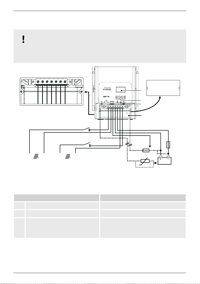
3.1
Controller power unit
NOTICE!
The power unit connector assignments of the MPPT 6000-M and MPPT 6000-S are identical.
The MPPT 6000-M and MPPT 6000-S differ in the additional components that can be
connected.
Fig. 2: Overview of the casing and connections on the power units for the MPPT 6000-M and MPPT
6000-S
Component Description
1 Display
2 Operating buttons
3 2 x RJ45 sockets for StecaLink slave
(MPPT 6000-S)
756.404 | Z01 | 16.06
ESC, D, Ñ, SET
Service interface for technical professionals,
connection to an MPPT 6000-M and connection
to additional StecaLink expansion devices such
as (e.g.) the PA HS400.
11
Page 12
Component Description
4 Terminal area
n "M1+"/"M1−" (solar module 1)
n "M1+"/"M1−" (solar module 2)
n "B+"/"B−" (battery)
n "PE" (ground)
n "BAT+/−" (battery voltage sensor cable)
n "TEMP" (ext. battery temperature sensor)
5 Terminal cover The terminal cover is fastened with 2 Phillips
screws.
External components Description
6 Solar module 1 Connect to terminals "M1+" and "M1−".
7 Solar module 2 Connect to terminals "M2+" and "M2−".
8 Battery Connect to terminals "B+" and "B−".
9,
DC load circuit breaker 4) for solar
10
module1/2
Danger
Danger from electrical voltage. Installation is
legally prescribed!
11 External battery temperature sensor
PA TS-S
3)
2)
3)
12 Battery voltage sensor cable connection
2)
13 External battery fuse (safety fuse or DC
circuit breaker
12
1) 4)
Attention
Use only an original Steca PA TS-S sensor. The
connection polarity is unimportant.
n Connect the cable directly to the battery.
n Observe the polarity specified in the
drawing.
Caution
Danger from high currents. Installation is legally
prescribed!
756.404 | Z01 | 16.06
Page 13
External components Description
11
1
9
15 20 17 16
18
12
14 Central grounding point If a grounding point is not already present then
this must be created, e.g. by hammering in a
grounding spike! Using the PE connection on
the MPPT 6000-M and MPPT 6000-S is legally
prescribed.
15 Fuse for battery voltage sensor cable The installation is mandatory if the optional
battery voltage sensor cable is used!
1)
For technical data see
2)
Optional, connector included in the scope of delivery. Connecting cable not included in the scope
Ä
Chapter 12 ‘Technical data’ on page 124.
of delivery.
3)
Included in the scope of delivery with the 6000-M.
4)
Not included in the scope of delivery.
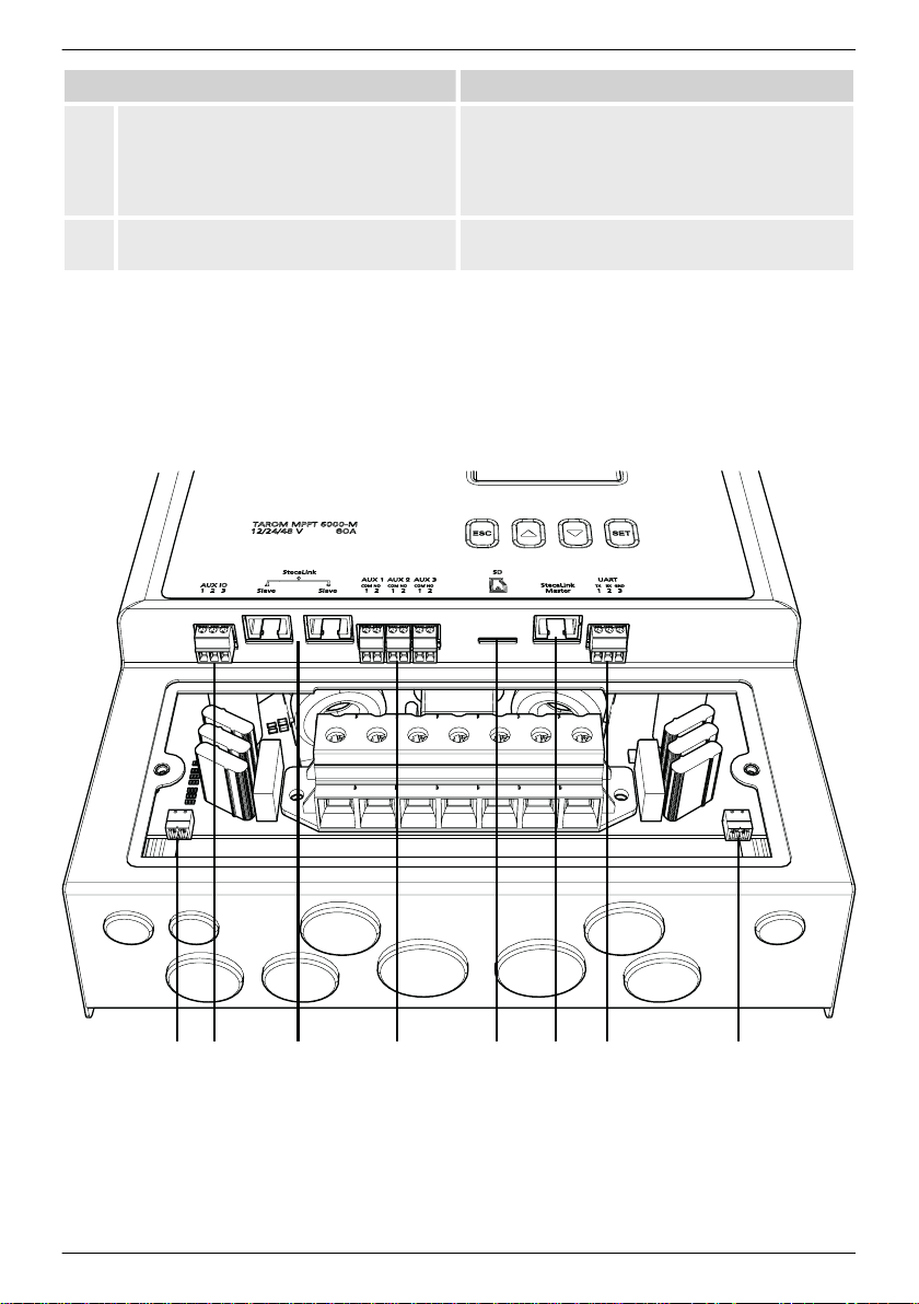
3.2 Additional connections on the MPPT 6000-M
Fig. 3: Overview of additional connections on the MPPT 6000-M
756.404 | Z01 | 16.06
13
Page 14
Component Description
15 2 x RJ45 sockets for StecaLink Slave
(MPPT 6000-M)
16 1 x RJ45 socket for StecaLink Master
(MPPT 6000-M)
17
Slot for microSD card 4) (MPPT 6000-M)
Service interface for technicians and connection
for superordinate StecaLink systems.
Connection for subordinate StecaLink
extensions such as e.g. PA HS400, MPPT 6000-S.
MicroSD card for data logging and storing
parameters.
18
Open UART interface
+5 V/0 V/-5 V (MPPT 6000-M)
19
AUX IO input 2) (MPPT 6000-M)
1) 2)
, RS-232 levels of
RS-232 data output, with Tx, Rx, GND
connections.
Remote control input for activating/deactivating
charging of the battery.
20
AUX 1/2/3 outputs 2) (MPPT 6000-M)
Programmable, potential-free relay outputs for
various control functions.
External components Description
11 External battery temperature sensor
PA TS-S
3)
Attention
Use only an original Steca PA TS-S sensor. The
connection polarity is unimportant.
12 Battery voltage sensor cable connection
2)
n Connect the cable directly to the battery.
n Take care to ensure the correct polarity, as
shown in Fig. 2, terminal area
enlargement.
1)
For technical data see
2)
Optional, connector included in the scope of delivery. Connecting cable not included in the scope
Ä
Chapter 12 ‘Technical data’ on page 124.
of delivery.
3)
Included in the scope of delivery with the 6000-M.
4)
Not included in the scope of delivery.
14
756.404 | Z01 | 16.06
Page 15
3.3 Additional connections on the MPPT 6000-S
11
12
3
Fig. 4: Overview of additional connections on the MPPT 6000-S
Component Description
3 2 x RJ45 sockets for StecaLink Slave
(MPPT 6000-S)
Service interface for technical professionals and
connection to an MPPT 6000-M and connection
to additional StecaLink expansion devices such
as (e.g.) the PA HS400.
756.404 | Z01 | 16.06
15
Page 16
External components Description
11 External battery temperature sensor
PA TS-S
3)
Attention
Use only an original Steca PA TS-S sensor. The
connection polarity is unimportant.
12 Battery voltage sensor cable connection
2)
n Connect the cable directly to the battery.
n Observe the polarity specified in the
drawing.
13 External battery fuse (fuse or DC circuit
breaker)
1) 4)
Caution
Danger from high currents. Installation is legally
prescribed!
14 Central grounding point If a grounding point is not already present then
this must be created, e.g. by hammering in a
grounding spike! Using the PE connection on
the MPPT 6000-M and MPPT 6000-S is legally
prescribed.
1)
For technical data see
2)
Optional, connector included in the scope of delivery. Connecting cable not included in the scope
Ä
Chapter 12 ‘Technical data’ on page 124.
of delivery.
3)
Included in the scope of delivery with the MPPT 6000-M.
4)
Not included in the scope of delivery.
16
756.404 | Z01 | 16.06
Page 17
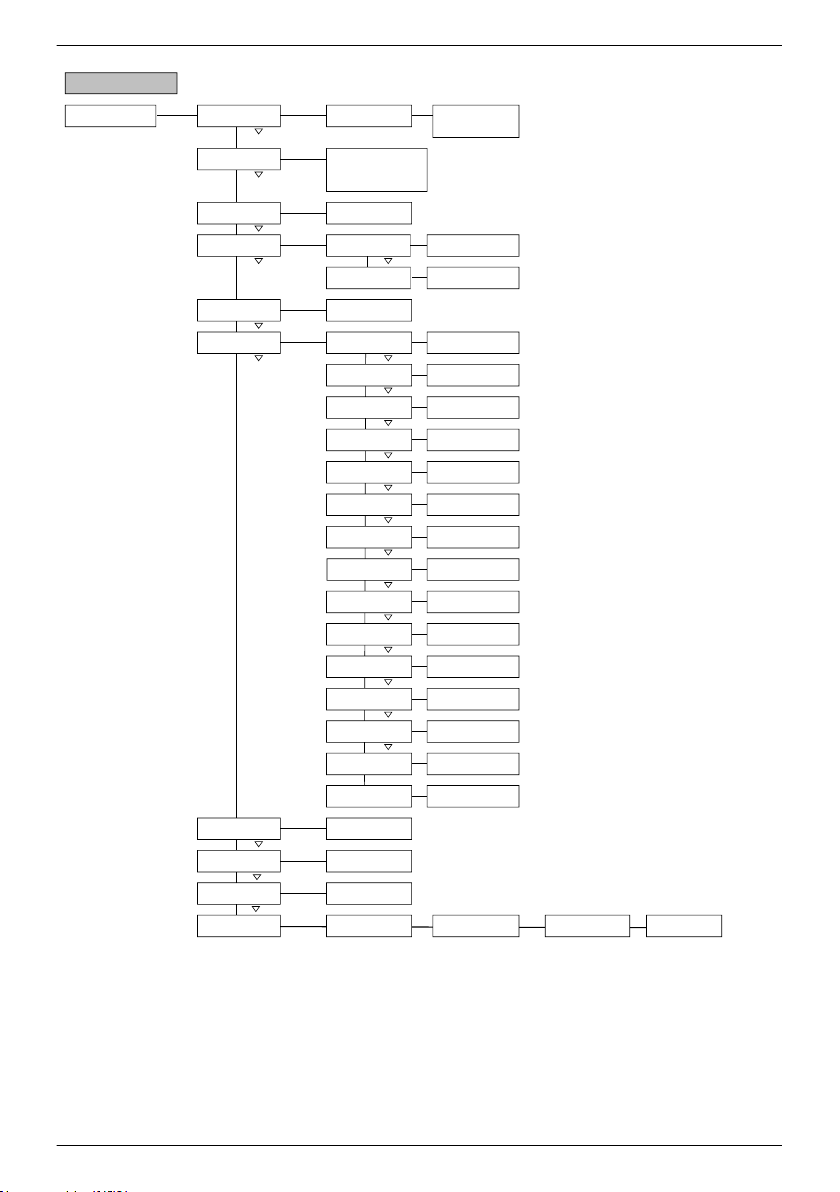
3.4 Menu structure
Set Set
Set Set
A)
Set
Set Set Set
Set
Set Set
B)
Set
Set Set Set
C)
Set
Set Set Set
D)
Set Set Set
E)
Set Set Set
F)
Set
Set Set
Set
Set
Set
Set Set
Set Set Set
Set
Set
Set
Set
Set
Set Set
Set
Set
Set
Set
Set
*1) MPPT 6000-M only
*3) SOC Control mode only
*2) MPPT 6000-S only
Status display
Basic position
Main window
Charge current M PPT
Battery voltage
Voltage ext. bat. sens e
SOC
*1, *3
Result of capacity test
*1
PV 1 voltage
PV 2 voltage
PV power tot al
PV 1 power
PV 2 power
Operating hours
Total charge/discharge
current of battery
*1
Total discharge current of
battery
*1
Total charge/discharge
power of battery
*1
Total charge c urrent of
battery
*1
Device On/Off
Settings AUX 1/2/3
*1
Intern al dat a logg er
SD card
*1
System sett ings
Battery settings
Event log
Information
Energy input
Main menu
Device On/Off
[ ] On
[ ] Off
[ ] Remote *1 / [ ] Redundanc y *2
Energy output
*1
Min. battery voltage
Max. battery voltage
Max. charge current
Max. PV 1 voltage
Max. PV 2 voltage
Last 18 hours
Day
Month
Year
Total
Configuration
*1
Graphic
List for last 30 days
Ah
List for last 12 months
Ah
Total yield info
Ah
List for last 20 years
Ah
Energy input members
[ ] MPPT power unit
[ ] …..
Graphic
Graphic
Last 18 hours
Day
Month
Year
Total
Configuration
*1
Graphic
List for last 30 days
Ah
List for last 12 months
Ah
Total yield info
Ah
List for last 20 years
Ah
Energy output members
[ ] MPPT power unit
[ ] …..
Graphic
Graphic
List for last 30 days
V
List for last 30 days
V
List for last 30 days
A
List for last 30 days
V
List for last 30 days
V
Power information from
StecaLi nk s lave
participants
*1
For the sake of clarity, only the Ñ
and SET operating buttons are illustrated.
756.404 | Z01 | 16.06
17
Page 18
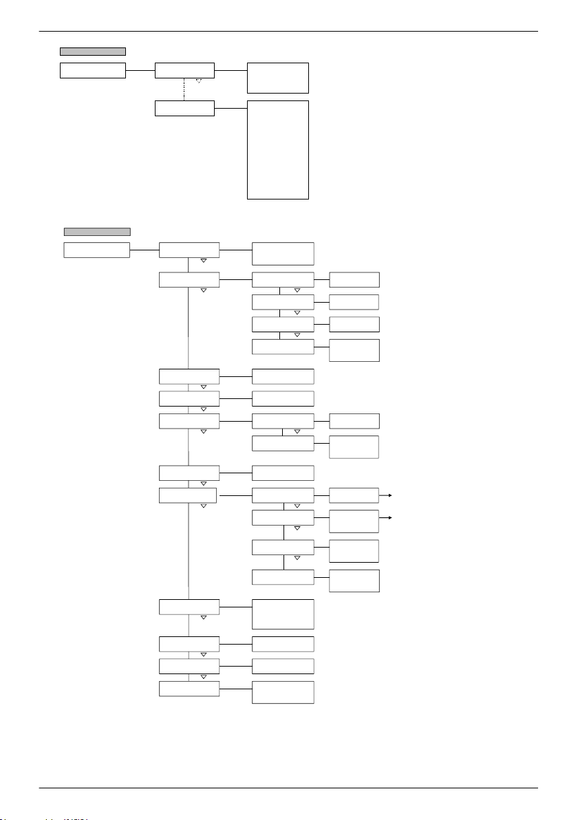
Set Set
Set
Set
Set
Set
Same scope of settings for AUX1/2/3
Set
Set Set
*5
Set
*5
Set
*5
Set
Set
Set
Set
Set
Set
*1) MPPT 6000-M only
*3) SOC Control mode only
*5) Separate entry of hh and mm, therefore press multiple times to change to the next window
Same scope of
settings for timer 1/2/3/4
*4) Voltage control mode only
Settings AUX 1/2/3
*1
AUX 1
AUX 2
AUX 3
Operation mode
Deep dischar ge p rot.
Select function
Function settings
AUX op eration mode
[ ] On
[ ] Off
[ ] Function
Disconnection threshold
SOC *3 / V *4
Reconnection hys teresis
SOC *3 / V *4
Select AUX func tion
[ ] Evening light
[ ] Night light
[ ] Morning light
[ ] G enerator con trol
[ ] E xcess energy contr ol
[ ] Timer 1
[ ] Timer 2
[ ] Timer 3
[ ] Timer 4
Evening light
Night light
Morning light
Generator control
Excess energ y con trol
Timer 1
Timer 2
Timer 3
Timer 4
Switch-on delay
00:00
Switch-on duration
00:00
Switch-on delay
00:00
Switch-off delay
00:00
Switch-off delay
00:00
Switch-on duration
00:00
Starting threshold
SOC *3 / V *4
Hyster esis
SOC *3 / V *4
Starting threshold
SOC *3 / V *4
Hyster esis
SOC *3 / V *4
Switch-on day
MON_TUE_WED_THU_FRI_SAT_SUN
Switch-on time
00:00
Switch-off day
MON_TUE_WED_THU_FRI_SAT_SUN
Switch-off time
00:00
A)
Set Set
Set
Set
Set
Set
Same scope of settings for AUX1/2/3
Set
Set
Set
*5
Set
*5
Set
*5
Set
Set
Set
Set
Set
Set
*1) MPPT 6000-M only
*3) SOC Control mode only
*5) Separate entry of hh and mm, therefore press multiple times to change to the next window
Set Set
Set
Set
*1) MPPT 6000-M only
Same scope of
settings for timer 1/2/3/4
*4) Voltage control mode only
Settings AUX 1/2/3
*1
AUX 1
AUX 2
AUX 3
Operation mode
Deep discharge prot.
Select function
Function settings
AUX operation mode
[ ] On
[ ] Off
[ ] Function
Disconnection threshold
SOC *3 / V *4
Reconnection hysteresis
SOC *3 / V *4
Select AUX function
[ ] Evening light
[ ] Night light
[ ] Morning light
[ ] Generator control
[ ] Excess energy control
[ ] Timer 1
[ ] Timer 2
[ ] Timer 3
[ ] Timer 4
Evening light
Night light
Morning light
Generator control
Excess energy control
Timer 1
Timer 2
Timer 3
Timer 4
Switch-on delay
00:00
Switch-on duration
00:00
Switch-on delay
00:00
Switch-off delay
00:00
Switch-off delay
00:00
Switch-on duration
00:00
Starting threshold
SOC *3 / V *4
Hysteresis
SOC *3 / V *4
Starting threshold
SOC *3 / V *4
Hysteresis
SOC *3 / V *4
Switch-on day
MON_TUE_WED_THU_FRI_SAT_SUN
Switch-on time
00:00
SD card
*1
Datalogger On/Off
Load parameter
Store parameter
[ ] On
[ ] Off
Load parameter
[ ESC ] [ 1s ]
Switch-off day
MON_TUE_WED_THU_FRI_SAT_SUN
Switch-off time
00:00
A)
B)
Store parameter
[ ESC ] [ 1s ]
Set
Event log
E)
01/30 Event message
30/30 Event message
18
756.404 | Z01 | 16.06
Page 19
Set
Set Set
Set
Event log
E)
01/30 Event message
30/30 Event message
F)
Information
Contact info
System info
Manufacturer
Address
Email
QR code
Platform name
Serial num.
PU version
- APP
- FBL
- BFAPI
- HW
SYS version
- BFAPI
- FBL
- APP
- PAR
- HW
MPPT slave address
Manual
Set Set
Set Set
Set
Set
Set
Set
Set
Set Set
Set
Set
Set Set
Set
Set
Set
Set
Set
Set
Set
*1) MPPT 6000-M only
… further menu entries
depending on the Slave properties
… further menu entries
depending on the Slave properties
System settings Language
Time / date
Clear log data
Clear event log
Display settings
StecaLink slave addr.
StecaLink master menu
*1
Mode AUX IO
*1
RS-232 port
*1
Acoustic alarm
Factory reset
[ ] english
[ ] deutsch
[ ] ….
Time
Date
Time format
Date format
Time
00:00
Date
11.12.2015
[ ] yyyy-mm-d d
[ ] dd.mm.yyyy
[ ] mm/dd/yyyy
[ ] 12h
[ ] 24h
Are you sure?
[ ESC ] [ 1s ]
Contrast
Backlight
Value
50%
[ ] Off
[ ] Automatic
[ ] Power mode
RS485 address
1 - 99
Add slave device
Change slave settings
Delete slave
Synchronise
Set slave address 1
-99
[ ] MPPT 6000
[ ] HS400
[ ] ….
Synchronise all
slaves
[ ESC ] [ 1s ]
[ ] Ext. voltage on
[ ] Ext. voltage off
[ ] Ext. switch on
[ ] Ext. switch off
C)
Are you sure?
[ ESC ] [ 1s ]
[ ] MPPT 6000
[ ] HS400
[ ] ….
[ ] On
[ ] Off
[ ] On
[ ] Off
Reset a ll values
[ ESC ] [ 1s ]
756.404 | Z01 | 16.06
19
Page 20
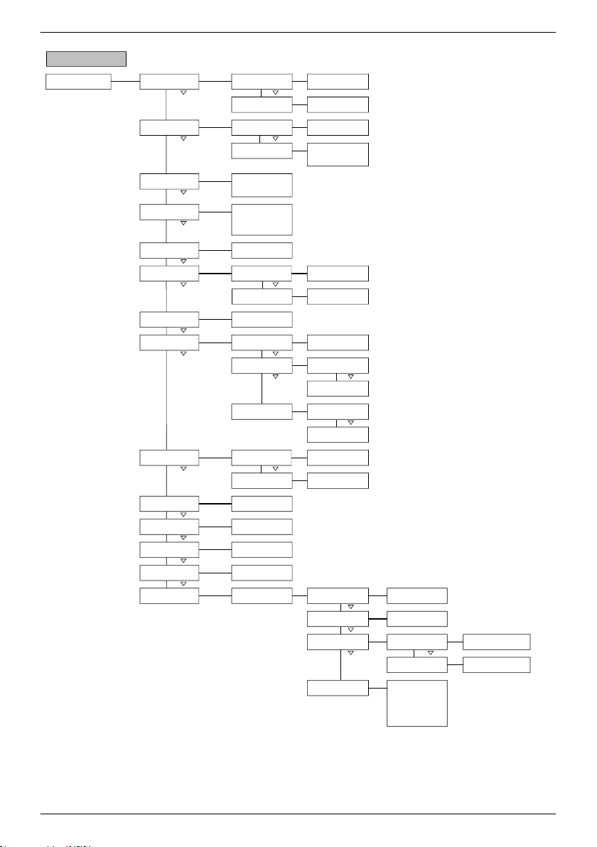
Set Set Set
Set
Set Set
Set
Set
Set
Set
Set Set
Set
Set
Set Set
Set
Set
Set Set
Set
Set
Set
Set
Set
Set Set Set
[1s]
Set
Set Set
*1) MPPT 6000-M only
*3) SOC Control mode only
Set
*5) Lead acid battery only
Set
*4) Voltage control mode only
Battery settings Equalisation cycle *5
Batter y con trol mode
*1
Battery capac ity test
*1
Battery type
Batter y cap acity
Charge voltag es
IUIA charge mode
*1
Start boost charg e
Bat. temperat ure sensor
Cable compens ation
PV string connection
Expert menu
On/Off
Cycle Duration
30 days
SOC control mode
Sensor member lis t
Capacity
100 Ah
Float charg ing
Boost chargi ng
Equalisation c harging
*5
Cycle
Code
17038
Equal. charge duration
*5
Boost charge dur ation
Temp. compensation
System voltag e
Duration
240 min
Temperat ure coeff icient
-4 mV/K/cell
D)
Leadacid/LeadGel/AGM
[ ] On
[ ] Off
[ ] State of charge (SOC)
[ ] Voltage control
[ ] MPPT 6000
[ ] HS400
[ ] ….
Charging deactivated !
Are you sure?
[ ESC ] [ 1s ]
[ ] Lead acid battery
[ ] Lead Gel/AGM
[ ] Li-Ion battery *1
[ ] NiCd battery *1
Current limit system *1
Current lim it device
On/Off [ ] On
[ ] Off
Value Limit
1605.0 A
Limit
60.0 A
Float charg e voltag e
56.4 V
Starting threshold
SOC *3 / V *4
Boost charge voltag e
57.6 V
Starting threshold
SOC *3 / V *4
Equal. charge voltage
60.0 V
On/Off [ ] On
[ ] Off
Cycle
6 month
Are you sure?
[ ESC ] [ 1s ]
[ ] Internal
[ ] External
[ ] On
[ ] Off
[ ] s eparated
[ ] parallel
Duration
120 min
On/Off
Temp. coefficient
[ ] On
[ ] Off
[ ] Automatic
[ ] 12V
[ ] 24V
[ ] 36V
[ ] 48V
[ ] 60V
20
756.404 | Z01 | 16.06
Page 21
Set Set Set
Set
Set
Set Set
Set
Set
Set Set
Set
Set
Set
Set
Set
Set
Set
Set
*1) MPPT 6000-M only
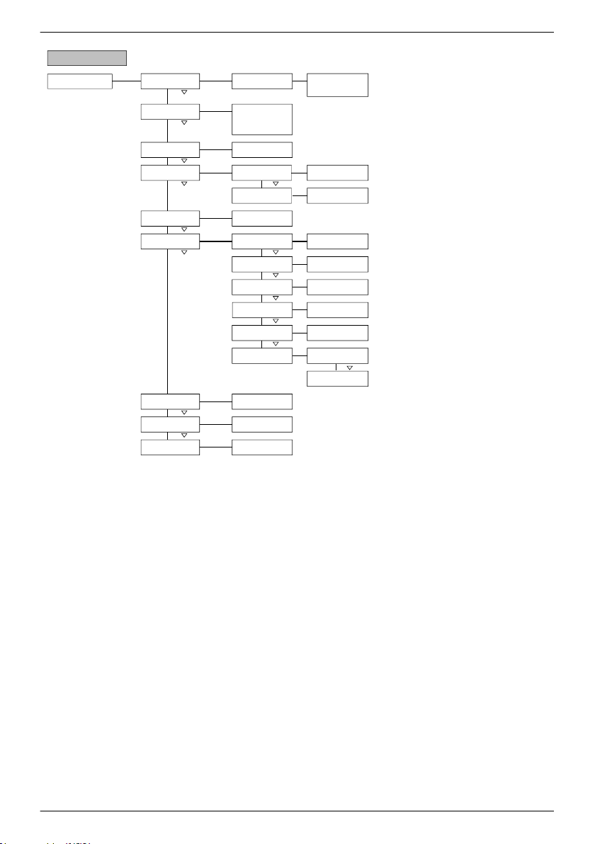
Battery settings
Batter y con trol mode
*1
Battery type
Batter y cap acity
Li-Ion battery settings
*1
Bat. temperat ure sensor
PV string connection
Sensor member lis t
Capacity
100 Ah
Number of cells
Cell voltage
Charge voltag e
Charge timer
D)
Li-Ion battery *1
[ ] MPPT 6000
[ ] HS400
[ ] ….
[ ] Lead acid battery
[ ] Lead Gel/AGM
[ ] Li-Ion battery *1
[ ] NiCd battery *1
Current lim it system *1
Current lim it device
On/Off [ ] On
[ ] Off
Value Limit
1605.0 A
Limit
60.0 A
Number of cells
7
Voltage per cell
3.7V
Min. temperature
0°C
Charge activ ation
Temperat ure range
[ ] Internal
[ ] External
[ ] s eparated
[ ] parallel
Voltage per cell
4.20V
Voltage per cell
4.00V
Charge timer
60min
Max. temperature
60°C
Cable compens ation [ ] On
[ ] Off
756.404 | Z01 | 16.06
21
Page 22
Set Set Set
Set
Set
Set Set
Set
Set
Set Set
Set
Set
Set
Set
Set
Set
Set
Set
Set
Set
Set
Set
Set
Set
Set
Set
Set
Set Set Set Set
[1s]
*1) MPPT 6000-M only
Battery settings B attery contr ol mode
*1
Battery type
Batter y cap acity
NiCd battery settings *1
Bat. temperat ure sensor
Sensor member lis t
Capacity
100 Ah
Upper charge voltage
U1
Temp. factor U1 (>0°C)
Fix DOD level
Charging time U1
D)
NiCd battery *1
[ ] MPPT 6000
[ ] HS400
[ ] ….
[ ] Lead acid battery
[ ] Lead Gel/AGM
[ ] Li-Ion battery *1
[ ] NiCd battery *1
Current lim it system *1
Current lim it device
On/Off [ ] On
[ ] Off
Value Limit
1605.0 A
Limit
60.0 A
Level charge voltage U1
1.50 V/cell
U1 tolerance for timer
DOD lev el c harge reset
[ ] Internal
[ ] External
Limit for charge volt.
U1
Lower DOD limit
U1 fac tor per DO D
Temp. factor U1 (<0°C)
Lower charge voltage
U2
Temp. factor U2 (>0°C)
Temp. factor U2 (<0°C)
Number of NiCd cells
U2 U1 switch
Limit charge volt. U1
1.65 V/cell
Lower DOD limit value
0.05
Value U1 f actor per DO D
5 mV
Value temp. factor U1
0.0 mV/K
Value temp. factor U1
-2.5 mV/K
DOD level
0.00
U1 tolerance level
50 mV
Duration charging time U1
50 min
DOD lev el c harge reset
0.02
Level charge voltage U2
1.50 V/cell
Value temp. factor U2
0.0 mV/K
Value temp. factor U2
-2.5 mV/K
Number of NiCd cells
7
Voltage level
1.00 V/cell
Cable compens ation [ ] On
[ ] Off
PV string connection
Expert menu Code
17038
Temp. compensation
[ ] s eparated
[ ] parallel
On/Off [ ] On
[ ] Off
22
756.404 | Z01 | 16.06
Page 23
4 Installation of the base system
Topics
1.
Ä
Chapter 4.1 ‘Safety instructions’ on page 23
2.
Ä
Chapter 4.2 ‘Installing the device’ on page 26
3.
Ä
Chapter 4.3 ‘Establishing the electrical connections’ on page 27
4.
Ä
Chapter 4.4 ‘Supplying the controller with voltage’ on page 31
4.1 Safety instructions
DANGER!
Risk of death by electrocution! Observe the following safety instructions when performing the
measures described in section
General information
n Only technical professionals may perform the work described in the section ‘Installation of the
base system’ .
n The PE connection must be connected to the system ground (grounding spike).
– If the system is to be positively grounded then "PE" must be additionally connected to
battery terminal "B+". The external battery fuse must then be installed in the "B−" cable!
With this grounding method, the module relay and battery relay provide safe isolation
from the PV module.
– This safe isolation from the PV module is disabled when the system is negatively grounded
via "B−" or "B−" and "PE". In the case of a simple fault (module relay does not open),
grounding of "B−" results in the "M−" potential being present on the casing of the MPPT
via the "PE" – ground connection. Only implement this grounding method when the system
has additional protection against touching live and electrically conductive system
components.
– Common grounding of "M1−/M2−" with "B−", "M1+/M2+" with "B+", "M1−/M2−" with "B
+" or "M1+/M2+" with "B−" is generally not permitted.
– The solar module frames can always be grounded.
n The solar module installation branch, including the DC load circuit breaker up to the controller
terminal area, must be implemented to protection class II.
n The battery installation branch must be implemented to protection class II.
n The following components must be installed:
– battery,
– at least 1 solar module,
– external battery fuse (safety fuse or DC circuit breaker) and
– a DC load circuit breaker for solar modules 1 and 2.
n Do not open the controller casing. Only the terminal cover may be removed by a technical
professional for installation.
Ä
‘Installation of the base system’ on page 23.
756.404 | Z01 | 16.06
23
Page 24
Always take the following measures before working on the controller:
1. Switch off all loads.
2. Switch off the DC load circuit breaker (solar module) and secure it against being switched on
again or safely cover the solar module (ensure that wind cannot blow off the covering!).
3. Switch off the external battery fuse: Remove the fuse insert from the fuse holder (safety fuse)
or switch off the DC line circuit breaker and secure it against being switched on again.
4. Disconnect the battery cable from both battery terminals.
Cable connections
n The module cables carry voltage when the solar module is illuminated.
n Insulate exposed cable ends with insulation tape or wire connector blocks.
n Connect the cables for the battery and solar module to the controller in the described sequence
( Fig. 1
).
n Secure the cables with a strain relief clamp. Clearance of strain-relief to controller: 200 mm.
n Connect only 1 cable to each connection terminal.
n Cable to be used: Observe the specifications in section
Ä
‘Technical data’ on page 124.
n Lay the cables so that:
– connections cannot accidentally come loose,
– persons cannot tread on or trip over these and
– fire protection devices are not impaired or obstructed.
n The entire installation must be designed with protection class II if the open-circuit module
voltage exceeds 60 V DC at least once anywhere over the entire temperature range.
n Observe all applicable installation regulations and standards, national laws and connection
values specified by the regional power supply company.
Fuses and switching devices
Installation of an external battery fuse (safety fuse or DC line circuit breaker) is mandatory! Observe
the following:
n Mount the external battery fuse directly next to the battery.
n The external battery fuse must conform to the specifications described in section
Ä
‘Technical
data’ on page 124.
n The external battery fuse is not included in the scope of delivery.
WARNING!
Danger of acid injuries
– Do not subject the battery to open flames or sparks.
Provide adequate ventilation in the installation location of the battery. Inflammable gases
–
can escape from the battery.
– Follow the charging instructions of the battery manufacturer.
24
756.404 | Z01 | 16.06
Page 25
CAUTION!
Danger of bodily injury. The device weighs over 6 kg. If in doubt, install the device with two
persons.
CAUTION!
Danger of destroying the device through overloading
– Conform to the technical specifications, especially the connection values. See type plate
Ä
and section
‘Technical data’ on page 124.
– When selecting the solar module, note that the open-circuit module voltage is higher than
the value specified on the type plate at temperatures below 25 °C.
– Do not connect the solar module to 2 controllers in parallel. The solar module can however
be connected in parallel to both solar module inputs of one controller. Make the
appropriate settings under Battery settings è PV string connection!
– Installation of a fuse in the battery voltage sensor cable is prescribed by law.
NOTICE!
The following section describes only the installation of the controller. Observe the instructions
in the manual from the respective manufacturer when installing the external components.
756.404 | Z01 | 16.06
25
Page 26
4.2 Installing the device
CAUTION!
Danger of damage to the inverter and reduction of power. Observe the following safety
requirements during installation:
– The mounting location and immediate environment are permanently fixed, vertical, flat,
non-inflammable and not subject to constant vibration.
A free space of at least 60 mm must be present on all sides of the controller (③ in Fig. 5).
–
– The controller must be easily accessible and the display easily readable.
– The controller is mounted as close as possible to the battery; the prescribed minimum
safety clearance of 0.5 m between the controller and battery is adhered to.
– The controller must not be located
– outdoors or in a location subject to rain or splashing water,
– in dusty environments,
– in stalls with active animal husbandry or
– in direct sunlight.
– The battery cable is no longer than 2 m (recommended), to keep cable losses and the
compensation voltage as low as possible.
– Do not drill through the fastening openings ①/② (Fig. 5).
1. Select the mounting location under consideration of the previously mentioned safety
requirements.
2. Position the controller level on the mounting surface and mark the mounting holes through
the fastening openings ①/② shown in Fig. 5.
NOTICE!
The keyhole form of the two upper fastening holes makes it possible to first install the
screws for ① and then mark the holes to be drilled for ② with the device hung in place
(lower risk of incorrectly positioned drilled holes).
3. Remove the controller and drill the mounting holes.
26
756.404 | Z01 | 16.06
Page 27
4. Use the screws/dowels supplied to fasten the controller to the mounting surface.
60 mm
60 mm
60 mm
60 mm
ི
ི
ི
ི
ཱ
ཱ
Fig. 5: Fastening openings
① /②
and free space
③
4.3 Establishing the electrical connections
CAUTION!
Always make connections in the following sequence:
1. First connect the load and then the source.
Example: First connect the cable to the controller and then to the battery.
2. First connect the positive pole then connect the negative pole.
Example: First connect "B+" then connect "B–".
756.404 | Z01 | 16.06
27
Page 28
NOTICE!
Use the cable pass-through holes plugged with rubber stops on the bottom of the casing as
follows:
– 2 large cable pass-through holes for the battery cables;
5 medium-sized cable pass-through holes for the module and "PE" cables;
3 small cable pass-through holes for the sensor cables (1 as a reserve).
Feed each cable through the corresponding cable pass-through hole lying opposite to the
–
cable connection, see Fig. 2.
– Use a screwdriver to punch a hole in the rubber stop of the respective cable pass-through
hole.
4.3.1 Preparing the cables
1. Label the cable ends according to
2. Lay the battery and module cables directly next to each other. Do not yet connect the cables!
3. Connect the external battery fuse to the "B–" battery cable, in an easily accessible position
close to the battery (
4. Switch off the external battery fuse: Remove the fuse insert from the fuse holder (safety fuse)
or switch off the DC line circuit breaker and secure it against being switched on again.
5. Connect the DC load circuit breaker to the module cables "M1+" and "M2+" (
an easily accessible position close to the controller.
6. Switch off the DC load circuit breaker and secure it against being switched on again.
7. Remove the terminal cover (release the 2 fastening screws with a Phillips screwdriver).
4.3.2
Connect the battery cable and external battery fuse to the battery connection of the controller and
to the battery.
Connecting the battery
✔
No devices are connected to the battery.
CAUTION!
Danger of damage to the controller. Observe the maximum battery voltage as per
data’ on page 124.
Fig. 2 ⑬).
Fig. 2 ("M1+", "M1–", "M2+", "M2–", "B+", ...).
Fig. 2 ⑨/⑩), in
Ä
‘Technical
NOTICE!
We recommend installing the external battery fuse in the "B–" cable.
28
756.404 | Z01 | 16.06
Page 29
4.3.3 Connecting the battery voltage sensor
NOTICE!
The external battery voltage sensor cable allows the controller to directly measure the voltage
at the battery. This voltage value can be used for compensation of voltage drops across the
battery cables. This means that the voltage measurement is not affected by (e.g.) powerdependent voltage drops across the battery cables.
A 2-pin plug with screw terminals for connecting the sensor cable is supplied with the device.
-
A cable with a cross-section of 0.14-1.5 mm2 (AWG 28-16) can be used.
The necessary sensor cable is not supplied with the device.
-
✔
A sufficiently long battery voltage sensor cable conforming to the technical data is available.
DANGER!
Install a fuse in the connection between the battery voltage sensor cable and the battery. The
fuse rating must match the cross-section of the cable used. This protects the cable from
burning in the case of a short-circuit in the battery voltage sensor cable.
1. Fit the green 2-pin socket (supplied) to the other end of the cable.
2. Plug the 2-pin socket into the"BAT+/–" connection so that the "+" conductor is at the left and
the "–" conductor is at the right; see the enlarged view of the terminal area in
3. Install an external fuse for protecting the battery voltage sensor cable.
4. Connect the battery voltage sensor cable directly to the battery; see ⑫ in Fig. 2.
5. Activate usage of the battery voltage sensor cable in the cable compensation settings.
‘Battery settings è Cable compensation
’.
Fig. 2.
4.3.4 Connect the ground (PE)
DANGER!
Risk of death by electrocution. The controller must be grounded via PE (controller has
protection class I).
756.404 | Z01 | 16.06
29
Page 30

CAUTION!
Danger of damaging the devices (e.g. computer) connected to the StecaLink master bus,
StecaLink slave bus or the UART interface. The galvanic isolation normally present at the AUX
IO, StecaLink master/slave bus and UART connections is disabled if the connected peripheral
devices are connected to the "PE" connection of the controller via a common ground/
equipotential bonding cable.
If the entire system is commonly grounded then all StecaLink bus connections, UART connections
and AUX IO connections must be additionally externally galvanically isolated!
è Connect the ground cable to the "PE" terminal.
4.3.5
1. Safely cover the module (ensure that wind cannot blow off the covering!).
2. Connect the module cable with the (open) DC load circuit breaker to the solar module
3. Remove the covering from the solar module.
Connecting the solar module
connection of the controller and the solar module as follows:
n A common DC load circuit breaker (in the common part of the module cable), when 1
solar module is connected in parallel to solar module inputs "M1" and "M2".
n Two separate DC load circuit breakers, when 2 solar modules are each separately
connected to solar module inputs M1 and M2; see Fig. 2.
4.3.6
è Install suitable lightning protection.
30
Install lightning protection
756.404 | Z01 | 16.06
Page 31

4.4 Supplying the controller with voltage
✔ At least the battery and the solar module have been connected as described previously.
1. Fit the terminal cover so that the danger notice is legible (and not upside-down).
2. Fit the fastening screws.
3. Switch on the external battery fuse: Insert the fuse insert into the fuse holder (safety fuse) or
switch on the DC line circuit breaker. The controller automatically starts operating, displays
the company logo after a few seconds and then displays the detected system voltage in an
event message (System voltage xx V) or RTC not set ( Fig. 6).
NOTICE!
English is set as the default menu language at the factory.
4.
Press D, Ñ to display the System voltage xx V. Note the displayed system voltage.
5. If additional event messages are displayed, or no messages are displayed (display dark), then
check the installation and if necessary correct the error using
on page 111.
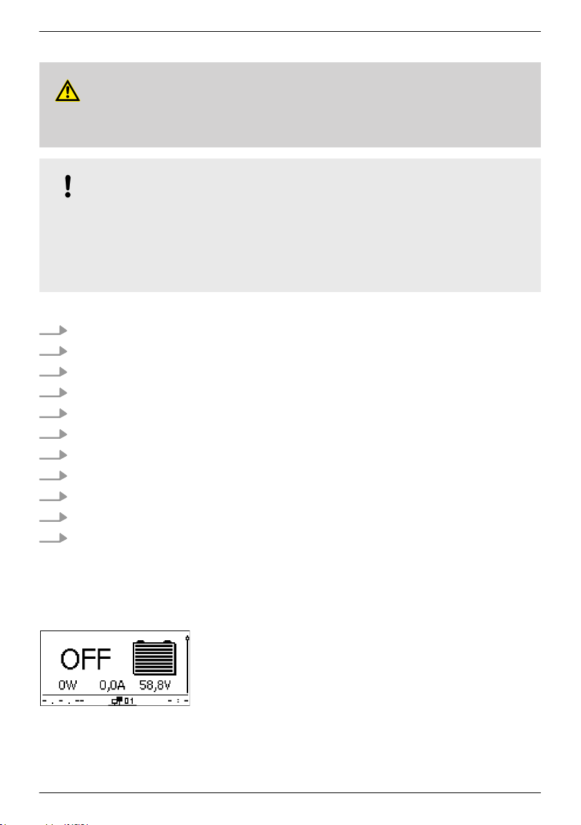
6. Press ESC to acknowledge the event message. The standard status display appears (
7. Check that the noted system voltage corresponds to the actual battery voltage. If not, then
set the correct system voltage via the expert menu (‘Main menu è Battery settings
è Expert menu è System voltage
’;
Ä
Chapter 8.5.14 ‘Expert menu’ on page 72).
Ä
Chapter 10 ‘Troubleshooting’
Fig. 7).
NOTICE!
When commissioning an MPPT 6000-S slave in a master/slave system via the StecaLink bus, the
system voltage used locally at the device is specified by the MPPT 6000-M master, without
changing the information message at the MPPT 6000-S. In a master/slave system the system
voltage detection must always be checked, and corrected if necessary, at the master device.
When operating the MPPT 6000-S in single mode the system voltage detected at the device
must be checked as described. In systems with lead-acid batteries the detected system voltage
is used for defining the charge voltage and deep-discharge protection ranges. The detected
system voltage is only displayed for information when using Li-Ion or NiCd battery types. The
charging range is determined based on the configured number of battery cells.
Fig. 6: Event message with the detected system voltage (in the example: 48 V)
756.404 | Z01 | 16.06
31
Page 32

Fig. 7: Display after switching on the external battery fuse
NOTICE!
The battery can be charged from multiple sources. The following applies:
– The battery can be charged by multiple controllers connected to the battery in parallel. The
MPPT 6000-M can assume control of other MPPT 6000-S devices. In this type of master/
slave system, a single MPPT 6000-M
can control up to 22 MPPT 6000-S devices.
– MPPT 6000-M only: Other suitable charging sources can also be connected to the battery
in addition to the controller. These charging sources can be switched on and off by the
controller via relay outputs AUX 1–3.
– MPPT 6000-M only: The controller can only perform sensible calculation of the state of
charge (SOC) when it is able to measure the charge and discharge currents of additional
sources and loads via additional PA HS400 current sensors.
– We recommend having the connection of additional controllers and other charging
sources planned by a technical expert.
32
756.404 | Z01 | 16.06
Page 33
5 Initial commissioning of the base system
CAUTION!
Danger of damage to the device and reduction of power. Only technical professionals may
perform the work described in this section.
NOTICE!
A basic system consists of only a single MPPT 6000-M or a single MPPT 6000-S. The description
of the initial commissioning process only covers the absolute minimum settings necessary.
Please consult the relevant sections below for information on further configuration possibilities.
To install and commission a master/slave system the individual units are installed as specified
according to the respective initial commissioning procedure but remain in the OFF
cabling is completed and all StecaLink bus settings in the master device have been completed.
Topics
1.
Ä
‘Show the basic setting of the status display’ on page 33
2.
Ä
‘Set the language’ on page 34
3.
Ä
‘Set the time’ on page 34
4.
Ä
‘Set the date’ on page 34
5.
Ä
‘Set the battery type’ on page 35
6.
Ä
‘Set the battery capacity’ on page 36
7.
Ä
‘Setting the charge parameters’ on page 36
8.
Ä
‘Switching on the cable compensation’ on page 37
9.
Ä
‘Configuring the temperature sensor’ on page 38
10.
Ä
‘Setting the PV string connection’ on page 38
11.
Ä
‘Finishing initial commissioning’ on page 39
state until all
✔All the measures described in
full.
Show the basic setting of the status display
756.404 | Z01 | 16.06
Ä
‘Installation of the base system’ on page 23 have been taken in
If necessary, press ESC for 1 s to show the basic setting of the
u
status display.
33
Page 34
Set the language
Set the time
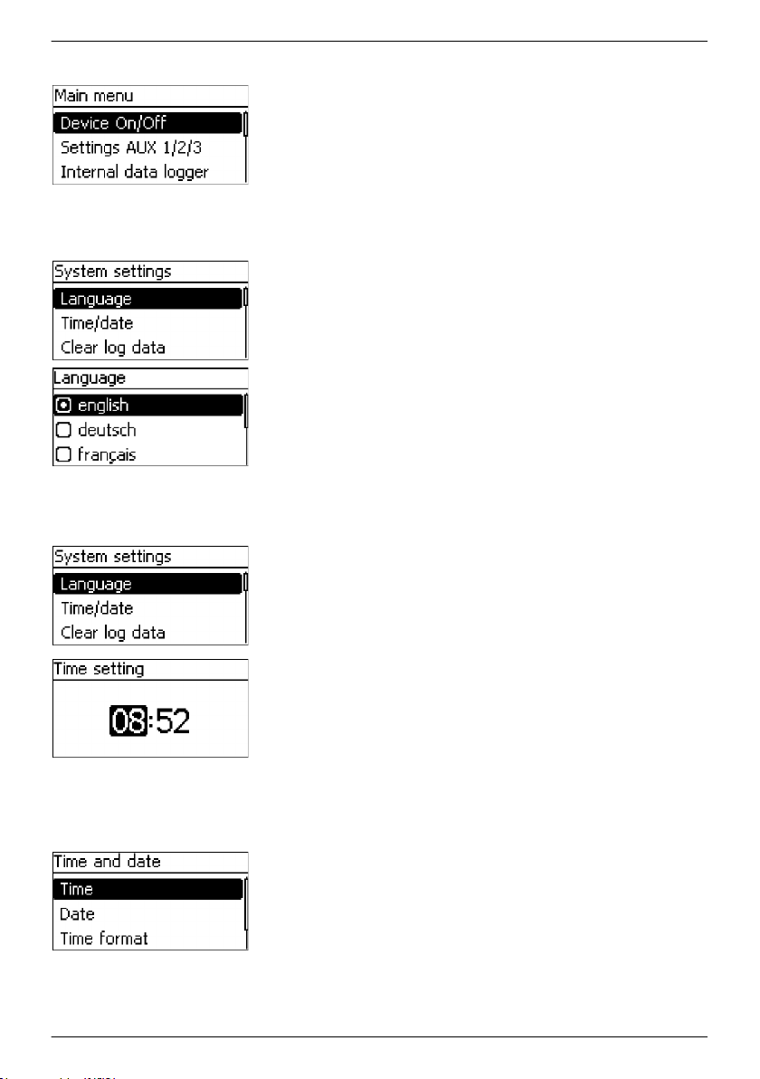
1. Press SET. The main menu appears and the Device On/Off
entry is selected (Fig. left).
NOTICE
English is set as the default menu language at the factory. In a
master/slave system, enabling the Save setting
parameter
for the slave allows the language setting of the master to be
transferred to the slave, see
Ä
Chapter 8.8.3 ‘Changing the
MPPT 6000-S slave settings (MPPT 6000-M only)’ on page 87.
2.
Press Ñ until System settings is selected.
3. Press SET. The System settings menu appears and
Language is selected (Fig. left).
4. Press SET. The Language menu appears (Fig. left).
5.
Press D, Ñ to select another language as required.
6. Press SET.
7. PressESC, the System settings menu appears and the
selected language is active.
1. The System settings menu appears after completing the
language selection (Fig. left).
2.
Press Ñ to select Time/date.
3. Press SET. The Time and date menu appears and Time is
selected.
4. Press SET. The
Time setting dialogue appears (Fig. left).
5. Press SET. The hours display flashes.
6.
Press D, Ñ to change the hour.
7. Press SET. The hour stops blinking.
8.
Press Ñ. The minutes are selected.
9. Repeat steps 5 to 7 for the minutes.
Set the date
34
1. Press ESC. The Time and date menu appears (Fig. left).
2.
Press Ñ to select Date.
3. Press SET. The Date setting dialogue appears (Fig. left).
4. Press SET. The day flashes.
5.
Press D, Ñ to change the day.
6. Press SET. The day stops blinking.
7.
Press Ñ to select the month.
756.404 | Z01 | 16.06
Page 35
Set the battery type
8. Repeat steps 4 to 6 for the month.
9.
Press Ñ to select the year.
10. Repeat steps 4 to 6 for the year.
NOTICE
Correctly setting the time and date is essential for correct
operation of the device. In a master/slave system, enabling the
Save setting parameter for the slave allows the language
and time settings of the master to be transferred to the slave,
Ä
Chapter 8.8.3 ‘Changing the MPPT 6000-S slave settings
see
(MPPT 6000-M only)’ on page 87. In the case of a power
failure, the time and date settings are retained for approx. 4
days.
1. Press ESC for 1 s. The standard status display appears.
2. Press SET. The main menu appears.
3.
Press Ñ to select Battery settings.
4. Press SET. The Battery settings menu appears.
5.
Press Ñ to select Battery type.
6. Press SET. The Battery type dialogue appears (Fig. left).
7.
Press D, Ñ to select a different battery type.
8. Press SET. The selected battery type is set.
NOTICE
MPPT 6000-M: The following battery types can be selected:
n Lead acid battery
n Lead Gel/AGM battery
n Li-Ion battery
n NiCd battery
MPPT 6000-S: The following battery types can be selected:
n Lead acid battery
n Lead Gel/AGM battery battery
In a master/slave system, enabling the Save setting
parameter for the slave allows the Lead acid and Lead Gel/AGM
battery type settings of the master to be transferred to the
slave. Settings for the Li-Ion and NiCd battery types cannot be
stored in the
MPPT 6000-S. The MPPT 6000-M can however
function as the master and control the charge function of the
slaves for all battery types when the Master mode
configuration for the slave is active, see
Ä
Chapter 8.8.3
‘Changing the MPPT 6000-S slave settings (MPPT 6000-M only)’
on page 87.
756.404 | Z01 | 16.06
35
Page 36
Set the battery capacity
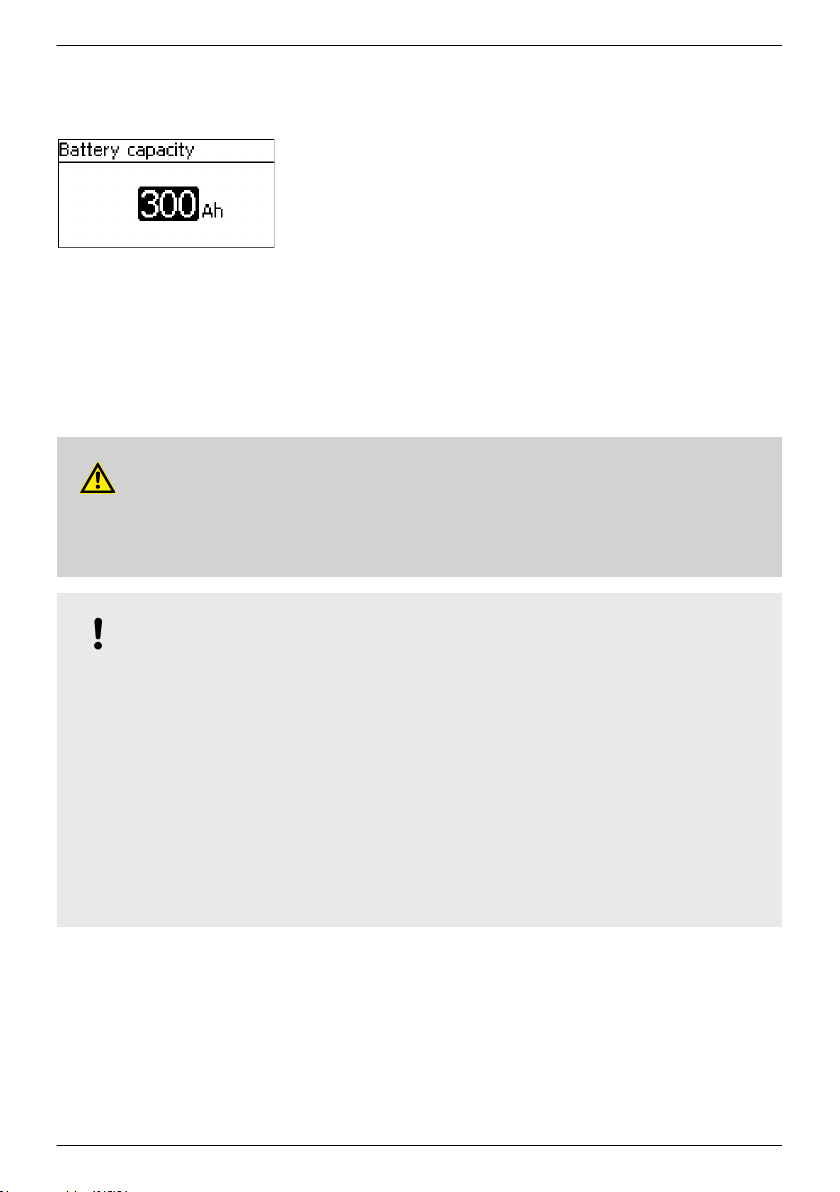
1. Press ESC. The Battery settings menu appears.
2.
Press Ñ to select Battery capacity.
3. Press SET. The Battery capacity dialogue appears (Fig.
left).
4. Press SET. The value flashes.
5.
Press D, Ñ to change the value.
6. Press SET. The value stops blinking.
NOTICE
Enter the specified nominal capacity of the battery here. This
value is required by functions such as the state of charge
calculation (SOC), IUIA charging and the capacity test. In a
master/slave system, enabling the Save setting
parameter
for the slave allows the battery capacity setting of the master
to be transferred to the slave.
Setting the charge parameters
WARNING!
Charging the battery with incorrect parameters can damage the battery. This can result in
conditions that are a danger to persons. Ensure that the correct charging parameters for the
selected battery type are used. Consult the battery manufacturer if necessary.
NOTICE!
Newly delivered
MPPT 6000-M and MPPT 6000-S devices are configured with the lead-acid
battery type. Always check the charge parameters.
– For the charge parameter settings applying to the lead-acid and lead-gel/AGM battery
Ä
types, see
– For the charge parameter settings applying to the Li-Ion battery type, see
Chapter 8.5 ‘Lead-acid battery system functions’ on page 62.
Ä
Chapter 8.6
‘Li-Ion battery system functions (MPPT 6000-M only)’ on page 74.
– For the charge parameter settings applying to the NiCd battery type, see
Ä
Chapter 8.7
‘NiCd battery system functions (MPPT 6000-M only)’ on page 77.
In a master/slave system, enabling the Save setting parameter for the slave allows the leadacid and lead-gel/AGM battery type settings of the master to be transferred to the slave. When
the slave has been configured with the Master mode operating mode then the slave is
controlled using the charge parameters configured in the master for all battery types.
36
756.404 | Z01 | 16.06
Page 37
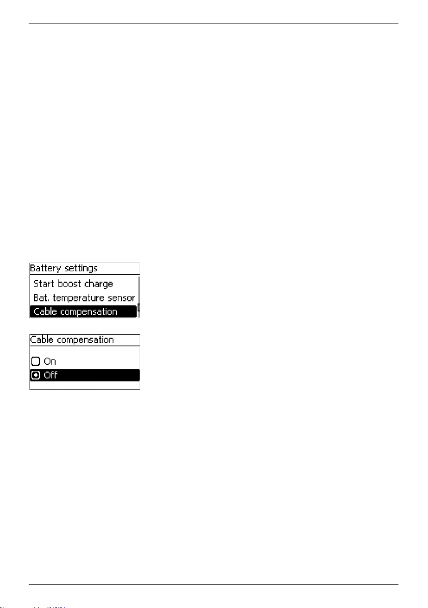
Switching on the cable compensation
The cable compensation corrects the deviation of the measured
battery voltage resulting from the voltage drop across the
battery cable.
NOTICES
n The unit is supplied with cable compensation switched off.
n The battery voltage sensor cable must be connected in
order to use cable compensation, see
Ä
Chapter 4.3.3
‘Connecting the battery voltage sensor’ on page 29.
n The voltage measured via the battery voltage sensor cable
is displayed in the measurements shown on the status
display of the device.
n Measuring the actual voltage at the battery allows the
device to compensate for voltage drops across the battery
cables. This can result in higher voltages at the battery
connection terminals on the controller.
n An Error event message is displayed if the battery voltage
sensor cable is not connected when the cable
compensation is switched on.
n If cable compensation is to be used in every member of a
master/slave system then this must be individually
installed and activated at each device.
1. Press ESC. The Battery settings menu appears.
2.
756.404 | Z01 | 16.06
Press D, Ñ to select Cable compensation (Fig. left).
3. Press SET. The Cable compensation dialogue appears (Fig.
left).
4.
Press D, Ñ to select On.
5. Press SET. The line compensation is switched on.
37
Page 38
Configuring the temperature sensor
The end-of-charge voltage can be adjusted according to the
measured ambient temperature of the battery. If an external
temperature sensor is used then this must be activated in the
corresponding menu.
NOTICES
n The external temperature sensor is switched off in newly
delivered devices. The internal sensor is used.
n We recommend connecting and using the external
temperature sensor supplied with the device
(MPPT 6000-M
only).
n In a master/slave system the master device performs the
central temperature compensation and controls the slaves
accordingly if these are configured for master-controlled
operation.
n MPPT 6000-M: An external temperature sensor must be
installed and activated for the battery capacity test
function.
See
Ä
Chapter 8.5.11 ‘Battery temperature sensor’ on page 71
for information on activating the PA TS-S external temperature
sensor.
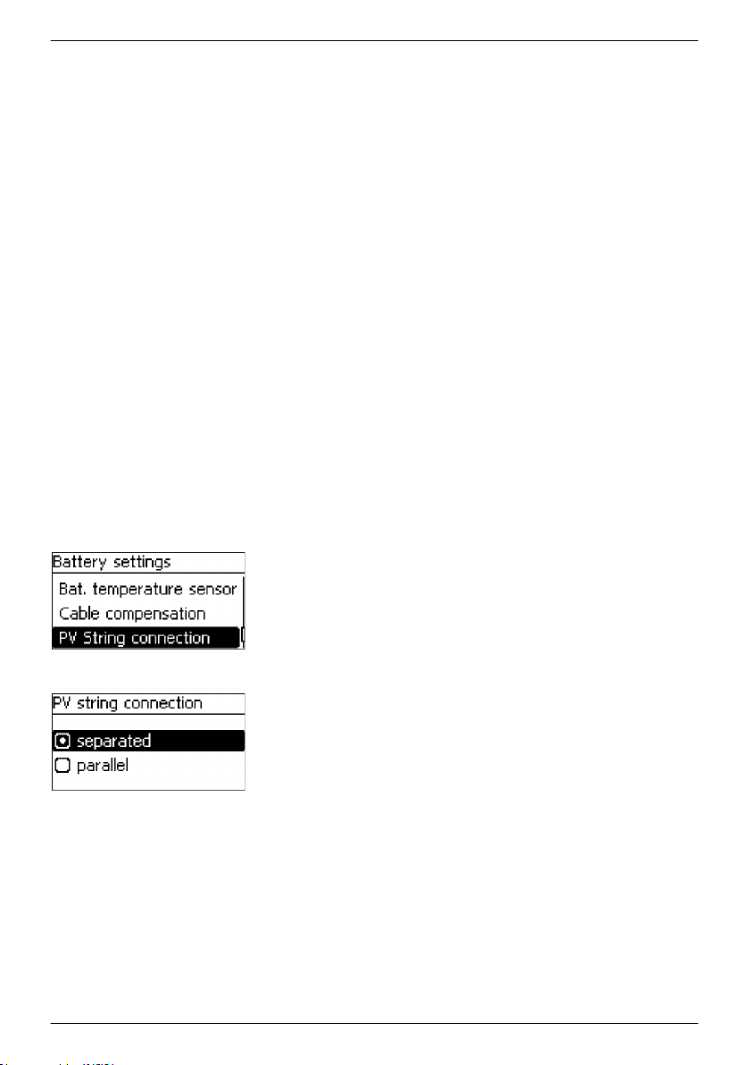
Setting the PV string connection
Newly delivered devices are configured for separate use of the
two module inputs "M1+/M1–" and "M2+/M2–". The PV string
connection parameter must be changed to "parallel" if both
module connections are wired in parallel.
1. Press ESC. The Battery settings menu appears.
2.
38
Press D, Ñ as required to select PV string connection (Fig.
left).
3. Press SET. The PV string connection dialogue appears
(Fig. left).
4.
Press D, Ñ to select parallel.
5. Press SET. The string connection is now changed to parallel
connection of the modules.
756.404 | Z01 | 16.06
Page 39

Finishing initial commissioning
NOTICE!
After completing basic installation of a master/slave system the devices must then be connected
via the StecaLink bus. Finish the installation of all devices before switching on any devices.
Ä
MPPT 6000-M, MPPT 6000-S: If further optional components,
Chapter 6 ‘Installation and
initial commissioning of optional components’ on page 40, are to be installed and configured,
finish the installation of all devices before switching on the unit.
Basic systems consisting of only one MPPT 6000-M or only one MPPT 6000-S can now be
switched on.
Press ESC for 1 s. The basic setting of the status display
u
appears and initial commissioning is finished.
1. Press SET. The Main menu appears.
2.
Press D, Ñ to select Device On/Off (Fig. left).
756.404 | Z01 | 16.06
3. Press SET. The Device On/Off dialogue appears (Fig. left for
the MPPT 6000-M
display. The MPPT 6000-S display is shown
below).
4.
Press D, Ñ to select On.
5. Press SET. The device switches on.
6. Press ESC for 1 s. The standard status display appears.
39
Page 40

6 Installation and initial commissioning of optional
components
Topics
1.
Ä
Chapter 6.1 ‘Commissioning the SD card (MPPT 6000-M only)’ on page 40
2.
Ä
Chapter 6.2 ‘AUX 1,2,3 relay output connection (MPPT 6000-M only)’ on page 41
3.
Ä
Chapter 6.3 ‘AUX IO remote control input connection (MPPT 6000-M only)’ on page 41
4.
Ä
Chapter 6.4 ‘PA TS-S external temperature sensor connection’ on page 43
5.
Ä
Chapter 6.5 ‘StecaLink slave connection’ on page 45
6.
Ä
Chapter 6.6 ‘StecaLink master connection (MPPT 6000-M only)’ on page 48
7.
Ä
Chapter 6.7 ‘UART/RS-232 interface connection (MPPT 6000-M only)’ on page 50
8.
Ä
Chapter 6 ‘Installation and initial commissioning of optional components’ on page 40
9.
Ä
Chapter 6.9 ‘Install cable strain relief’ on page 51
6.1 Commissioning the SD card (MPPT 6000-M only)
CAUTION!
Never forcibly insert or remove the microSD card. This can damage the card holder and/or the
microSD card.
NOTICE!
– A microSD card is not included in the scope of delivery for the device.
microSD and microSDHC cards with a capacity of up to 8 GB can be used.
–
– The microSD card must be formatted with a FAT16 or FAT32 file system.
– Data from the MPPT 6000-M and any connected StecaLink slave devices can be recorded
on the microSD card.
– Settings parameters for the MPPT 6000-M can be saved to and read from the microSD
card.
– Take care to observe the correct insertion direction, as shown on the microSD card and the
device.
– Carefully and gently push the microSD card into the opening in the device casing until it
latches into place.
– Remove the microSD card by pushing it further into the device until it unlatches, then let
go of the card and allow it to eject and finally pull the card out of the socket (Push-Pull
connector).
– Data recording onto the SD card is deactivated at the factory for newly delivered devices.
1. Insert a formatted microSD card.
2.
Configure the data logging function and save/load the parameters as described in
8.15 ‘SD card (MPPT 6000-M only)’ on page 101.
40
756.404 | Z01 | 16.06
Ä
Chapter
Page 41

6.2 AUX 1,2,3 relay output connection (MPPT 6000-M only)
CAUTION!
Ä
Danger of destruction of the relays. Observe the technical data of the relays, see
‘Technical data’ on page 124. Only use AUX 1/2/3 for switching DC voltages of max. 60 VDC.
NOTICE!
– A 2-pin plug with screw terminals for the external cable is supplied with the MPPT 6000-M.
Each AUX connection has a separate COM and NO connection.
–
– The relay outputs are potential-free, normally-open contacts.
– The initial state of the contacts is normally-open.
– Multiple different events can be assigned to the AUX 1/2/3 outputs. Multiple events are
combined as logical "OR" values.
– The relay outputs can be used for switching devices or loads.
– Heavy loads connected directly to the battery can be switched using an additional power
relay connected to the AUX connection, e.g via the Steca PA EV 200.
1. Connect the external components to the AUX relay outputs.
2.
Configure the relay outputs as described in
(MPPT 6000-M only)’ on page 103.
AUX 1 AUX 2 AUX 3 Description
1 (COM) 1 (COM) 1 (COM) Common relay contact
2 (NO) 2 (NO) 2 (NO) Normally open relay contact; the contact is open when the
relay is switched off.
Ä
Chapter 9 ‘Control functions via AUX 1/2/3
Chapter 12
6.3 AUX IO remote control input connection (MPPT 6000-M only)
CAUTION!
Ä
Risk of destroying the signal input. Observe the technical connection data, see
‘Technical data’ on page 124.
756.404 | Z01 | 16.06
Chapter 12
41
Page 42

NOTICE!
– The charging function can be switched on or off by external devices via the AUX IO signal
input.
An external signal voltage of 5 VDC - 24 VDC at max. 3 mA or an external contact can be
–
connected. The external contact must be able to switch max. 15 VDC at 5 mA.
– Connect an external signal voltage between AUX IO (1) and (2). AUX IO (1) is the GND,
AUX IO (2) is the signal voltage input.
– Connect an external contact between AUX IO (2) and (3).
– A 3-pin plug with screw terminals for the external cable is supplied with the MPPT 6000-M.
AUX IO Description
1 (GND) GND reference for external signal voltage.
2 (Signal input) External signal voltage input connection.
3 (Signal output) Signal output for external switch.
1. Connect the external control source to the AUX IO signal input.
2. Configure the AUX IO function.
3. Configure the Device On/Off control.
Configuration of the AUX IO control function
NOTICE!
– The following properties can be assigned to the AUX IO connection:
– Ext. voltage on
Application of an external voltage at the AUX IO connection switches on charging by
the MPPT 6000-M.
– Ext. voltage off
Application of an external voltage at the AUX IO connection switches off charging by
the MPPT 6000-M.
– Ext. switch on
The closing of an external switch at the AUX IO connection switches on charging by
the MPPT 6000-M.
– Ext. switch off
The closing of an external switch at the AUX IO connection switches off charging by
the MPPT 6000-M.
42
756.404 | Z01 | 16.06
Page 43

▶
Press ESC for 1 s. The standard status display appears.
1. Press SET. The Main menu appears.
2.
Press D, Ñ to select System settings (Fig. left).
3. Press SET. The System settings menu appears (Fig. left).
4.
Press D, Ñ to select Mode AUX IO.
5. Press SET. The Mode AUX IO
6.
Press D, Ñ to select the desired function.
dialogue appears (Fig. left).
7. Press SET. The selected function is activated.
8. Press ESC for 1 s. The standard status display appears.
Configuring Device On/Off control
NOTICE!
If the Device On/Off setting is not changed to Remote then the switching signal at the AUX
IO connection has no effect on the charging operation of the MPPT 6000-M.
1. Press SET. The Main menu appears.
2.
Press D, Ñ to select Device On/Off (Fig. left).
3. Press SET. The Device On/Off dialogue appears (Fig. left).
4.
Press D, Ñ to select Remote.
5. Press SET. The selected function is activated.
6. Press ESC for 1 s. The standard status display appears.
6.4 PA TS-S external temperature sensor connection
CAUTION!
Use only a Steca PA TS-S external temperature sensor approved for use with the device.
Incorrect sensors can lead to incorrect temperature compensation of the charge voltage and
damage the battery. Observe the safety notices in
on page 23 when connecting the sensor.
756.404 | Z01 | 16.06
Ä
Chapter 4.1 ‘Safety instructions’
43
Page 44

NOTICE!
– A PA TS-S external temperature sensor is supplied with the device (MPPT 6000-M only).
An event message of type Error is generated if the external temperature sensor is activated
–
but not connected.
If the controller and battery are not located in the same room then an external temperature
sensor for measuring the battery temperature must be installed. The polarity of the contacts for
the connection is irrelevant.
1. Mount the Steca PA TS-S temperature sensor close to the battery.
2. Insert the sensor cable plug into the TEMP connection (polarity irrelevant!). See
Fig. 2.
Activating an external temperature sensor
Press ESC for 1 s. The standard status display appears.
u
1. Press SET. The Main menu appears.
2.
Press D, Ñ as required to select Battery settings (Fig. left).
3. Press SET. The Battery settings menu appears (Fig. left).
4.
Press D, Ñ to select Bat. temperature sensor.
5. Press SET. The Bat. temperature sensor dialogue appears
(Fig. left).
6.
Press D, Ñ to select External.
7. Press SET. The external temperature sensor is now activated.
8. Press ESC for 1 s. The standard status display appears.
44
756.404 | Z01 | 16.06
Page 45

6.5 StecaLink slave connection
NOTICE!
– The StecaLink slave connection is an RS-485 communication interface using a proprietary
bus protocol.
The StecaLink slave connection allows connection of superordinate communication levels
–
and control devices. The superordinate communication partner functions as the master
and controls the device via the StecaLink slave interface.
– The StecaLink slave interface can be used for e.g. updating the firmware via a Windows PC
with an RS-485-/USB-adapter and Steca Grid Bootloader software.
– A standard RJ45 network cable (CAT-5 Patch cable, 1:1) is used for connecting StecaLink
communication bus members.
– The last unused StecaLink slave connection in a communication chain must be terminated.
A termination plug for the StecaLink communication bus is supplied with the MPPT 6000M.
– A StecaLink slave device may only be connected to
StecaLink slave devices are connected to form a communication chain. Only one StecaLink
slave device is connected to the StecaLink master device.
Up to 22 MPPT 6000-S devices can be chain connected via their StecaLink slave sockets to
–
the StecaLink master socket of the MPPT 6000-M.
– The StecaLink slave bus is galvanically separated from the power unit of the MPPT 6000-M.
– The MPPT 6000-M provides a supply voltage at the StecaLink slave and StecaLink master
connections for slave devices that do not have their own power supply. Connecting a slave
to the StecaLink master loops the supply voltage through the slave members.
– Each slave must have its own unique address within a range of 1 to 99. No duplicate
addresses may be present. Set the address of the slave according to the slave manual.
– The maximum length of the entire bus cabling should not exceed 25 m.
– The MPPT 6000-M:
– has 2 StecaLink slave bus connections,
– is a slave at the StecaLink slave connection,
– has a StecaLink master connection,
– is always the master at the StecaLink master connection.
– The MPPT 6000-S:
– has 2 StecaLink slave connections,
– is always a slave at the StecaLink slave connection.
one StecaLink master. Multiple
1.
Set a unique slave address at the device with the StecaLink slave connection; see
Ä
Chapter
8.8.1 ‘StecaLink slave address setting’ on page 86.
2. Connect the StecaLink slave connection to the ‘StecaLink master’ connection of the
superordinate master device.
3. Use a free ‘StecaLink slave’ connection for looping the connection through further slaves.
756.404 | Z01 | 16.06
45
Page 46

Tarom
MP
PT 6000-M
StecaLink
Slave Slave
StecaLink
Master
Tarom
MP
PT 6000-S
StecaLink
Slave Slave
......
Tarom
MP
PT 6000-S
StecaLink
Slave Slave
PA HS400
S
tecaLink
Slave Slave
......
PA HS400
S
tecaLink
Slave Slave
Term.
Tarom
MP
PT 6000-M
StecaLink
Slave Slave
StecaLink
Master
PA HS400
St
ecaLink
Slave Slave
......
PA HS400
St
ecaLink
Slave Slave
Term.
Tarom
MPP
T 6000-M
StecaLink
Slave Slave
StecaLink
Master
PC
StecaLink
Master
Tarom
MPP
T 6000-M
StecaLink
Slave Slave
StecaLink
Master
Tarom
MPP
T 6000-S
StecaLink
Slave Slave
4. Terminate the free ‘StecaLink slave’ connection of the last slave member using the
termination plug.
Fig. 8: Bus cabling example using an MPPT 6000-M, MPPT 6000-S and PA HS400 current sensors
Fig. 9: Bus cabling example using an MPPT 6000-M and additional PA HS400 current sensors
Fig. 10: Example of connecting a PC to the MPPT 6000-M, e.g. for the update function
Fig. 11: Connection of the MPPT 6000-M slave connection to other MPPT 6000-S or PA HS400 slave
connections is not permitted
46
756.404 | Z01 | 16.06
Page 47

The bus cable pin assignments are specified in the following table.
The StecaLink slave connection of the MPPT 6000-M and MPPT 6000-S is galvanically isolated from
the power unit.
Pin 1 2 3 4 5 6 7 8
Signal A B -
1)
The 15 VDC supply voltage for the slaves is looped through by the master device.
2)
GND for the 15 VDC supply voltage for the slaves. SGND is connected to GND/15 VDC in the MPPT
-/(15 VDC)
1)
- -
GND 2)/15 VDC SGND 3)/A,B
6000-M.
3)
SGND for signal lines A/B. Not connected to GND/15 VDC in the MPPT 6000-S. Connecting the
StecaLink slave socket to the StecaLink master socket creates a connection via the MPPT 6000-M, see
2)
.
756.404 | Z01 | 16.06
47
Page 48

6.6 StecaLink master connection (MPPT 6000-M only)
NOTICE!
– The StecaLink master connection is an RS-485 communication interface using a proprietary
bus protocol.
The StecaLink master connection allows the connection of subordinate communication
–
partners.
– The StecaLink slave devices connected to the StecaLink master connection are controlled by
the MPPT 6000-M functioning as the communication master device.
– Devices such as PA HS400 external current sensors or the MPPT 6000-S can be connected
to the StecaLink master connection.
– A standard RJ45 network cable (CAT-5 Patch cable, 1:1) is used for connecting StecaLink
communication bus members.
– A termination plug for the StecaLink communication bus is supplied with the MPPT 6000-
M. The last free StecaLink slave connection in the communication network connected to
the StecaLink master must be terminated.
– Only one StecaLink master may be connected to a StecaLink communication network.
– The maximum number of StecaLink slaves is limited. A maximum of 32 devices can be
connected to the StecaLink master connection of a single MPPT 6000-M.
– The MPPT 6000-M can control a maximum of 8 PA HS400 devices and 22 MPPT 6000-S
devices.
– Each slave must have its own unique address within a range of 1 to 99. No duplicate
addresses may be present. Set the address of the slave according to the slave manual.
– The StecaLink master connection is galvanically isolated from the power unit.
– The maximum length of the entire bus cabling should not exceed 25 m.
– The MPPT 6000-M:
– has 1 StecaLink master connection,
– has 2 StecaLink slave bus connections,
– is always the master at the StecaLink master connection.
– The MPPT 6000-S:
– does not have a StecaLink master connection.
48
756.404 | Z01 | 16.06
Page 49
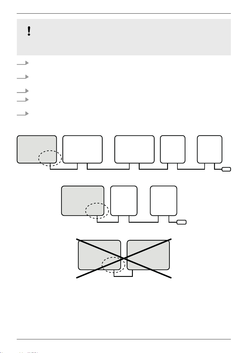
NOTICE!
Tarom
MP
PT 6000-M
StecaLink
Slave Slave
StecaLink
Master
Tarom
MP
PT 6000-S
StecaLink
Slave Slave
......
Tarom
MP
PT 6000-S
StecaLink
Slave Slave
PA HS400
S
tecaLink
Slave Slave
......
PA HS400
S
tecaLink
Slave Slave
Term.
Tarom
MP
PT 6000-M
StecaLink
Slave Slave
StecaLink
Master
PA HS400
St
ecaLink
Slave Slave
......
PA HS400
St
ecaLink
Slave Slave
Term.
Tarom
MP
PT 6000-M
StecaLink
Slave Slave
StecaLink
Master
Tarom
MP
PT 6000-M
StecaLink
Slave Slave
StecaLink
Master
MPPT 6000-S devices can be connected to each other when the MPPT 6000-M has a software
version of IFUSYS4 APP 1.5.0 or later.
1. Set a unique address at the device with the StecaLink slave connection. For the MPPT 6000-S,
Ä
Chapter 8.8.1 ‘StecaLink slave address setting’ on page 86.
see
2. Plug the slave device into the StecaLink master connection. Connect the ‘StecaLink master’
connection to the ‘StecaLink slave’ connection.
3. Additional slaves are connected to the free ‘StecaLink slave’ connection on the slave device.
4. Terminate the free ‘StecaLink slave’ connection of the last slave member using the
termination plug.
5.
Register and configure the added StecaLink slave devices at the MPPT 6000-M, see
Ä
Chapter
8.8.2 ‘StecaLink master setting (MPPT 6000-M only)’ on page 86.
Fig. 12: Bus cabling example using an MPPT 6000-M, MPPT 6000-S and PA HS400 current sensors
Fig. 13: Bus cabling example using an MPPT 6000-M and additional PA HS400 current sensors
Fig. 14: Master/slave connection of two or more MPPT 6000-M devices is not possible
756.404 | Z01 | 16.06
49
Page 50

Tarom
MPP
T 6000-M
StecaLink
Slave Slave
StecaLink
Master
Tarom
MPP
T 6000-M
StecaLink
Slave Slave
StecaLink
Master
Fig. 15: Connection of two MPPT 6000-M devices via the master connection is not possible
The bus cable pin assignments are specified in the following table.
The StecaLink master connection of the MPPT 6000-M is galvanically isolated from the power unit.
StecaLink bus cable pin assignment: see
Ä
further information on page 47.
6.7 UART/RS-232 interface connection (MPPT 6000-M only)
NOTICE!
– The UART connection on the unit provides a serial interface with RS-232-compatible signal
levels. See
– The interface can be used for sending data from the device to a PC.
– Data transmission from a PC to the device is not possible.
– A 3-pin plug with screw terminals for constructing an individual cable is supplied with the
device.
– TxD, RxD and GND (signal ground) are present at the 3-pin connection, see printed label.
– The serial interface is galvanically isolated from the power unit connections.
– The interface can be switched on and off.
– The data output is fixed by the device and cannot be changed.
– Data is output at 1 minute intervals.
– For information on the data content of the serial output, see
RS-232 interface protocol (MPPT 6000-M only)’ on page 142.
– After activating the UART interface it can take up to one minute before the first data is
output.
Ä
Chapter 12 ‘Technical data’ on page 124.
Ä
Chapter 12.3 ‘UART/
1. Connect an external receiving device to the UART connection.
2.
For information on activating data output at the MPPT 6000-M, see Ä Chapter 8.13 ‘UART/
RS-232 interface (MPPT 6000-M only)’ on page 100.
Pin assignments:
Pin 1 (TX) 2 (RX) 3 (GND)
Signal TX RX Ground
50
756.404 | Z01 | 16.06
Page 51
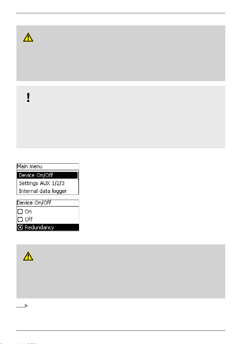
6.8 Redundancy function (MPPT 6000-S only)
CAUTION!
The redundancy function allows charging by the MPPT 6000-S to be automatically switched on
after a new start/reset or a failure in communication with the MPPT 6000-M in a master/slave
system. Before using the function, make sure that automatically switching on the charging
cannot lead to dangerous system states under all application and error conditions. If switching
off the MPPT 6000-M in a master/slave system should stop all charging processes then the
device control mode must be changed from Redundancy to Off.
NOTICE!
– The redundancy function at the MPPT 6000-S can be used in single-device mode and also
in master/slave mode.
The charging parameters used for the redundancy function correspond to the local
–
settings of the MPPT 6000-S or are adopted from the MPPT 6000-M via the Store
configuration parameter function. See
slave settings (MPPT 6000-M only)’ on page 87 ▶
on page 89.
✔
‘Main menu è Device On/Off
1.
Press D, Ñ to select Redundancy.
2. Press SET. Charging of the battery is now switched on
automatically.
Ä
Chapter 8.8.3 ‘Changing the MPPT 6000-S
Ä
‘Configuring the operating mode’
’
6.9 Install cable strain relief
CAUTION!
Danger of damage to the device. Secure all cables connected to the MPPT 6000-M/-S with a
strain relief fixture. This ensures that the cables cannot be unintentionally disconnected and
cause short-circuits or malfunctions.
The cable feed-throughs on the housing of the MPPT 6000-M/-S do not provide reliable strain
relief.
Secure the cables with a strain relief fixture. Clearance to controller: 200 mm.
756.404 | Z01 | 16.06
51
Page 52

7 Display (layout, function, operation)
1.
Ä
Chapter 7.1 ‘Operating buttons’ on page 52
2.
Ä
Chapter 7.2 ‘Overview/Menu structure’ on page 52
3.
Ä
Chapter 7.3 ‘Status display’ on page 53
4.
Ä
Chapter 7.4 ‘Display of special states’ on page 56
5.
Ä
Chapter 7.5 ‘General operation’ on page 56
6.
Ä
Chapter 7.6 ‘Advanced operation’ on page 56
7.
Ä
Chapter 7.7 ‘Display settings’ on page 58
7.1 Operating buttons
Button Function
SET
ESC
D, Ñ
n Navigates one menu level down.
n Changes the state of a control element (check box/radio button).
n Causes the selected numeral to blink so that it can be modified.
n Answers a query dialogue with Yes.
n Adopts a change.
n Navigates one menu level up.
n Jumps to the status display (press for 1 s).
n Answers a query dialogue with No.
n Discards any changes.
n Moves the selection bar or the display content upwards/downwards.
n Moves the selection 1 position to the left/right on a settings page.
n Increases/decreases a setting value by 1 step.
n Repeated button presses: Press button for a longer time.
7.2 Overview/Menu structure
An overview of the operating structure of the display is provided in
on page 17.
52
Ä
Chapter 3.4 ‘Menu structure’
756.404 | Z01 | 16.06
Page 53

7.3 Status display
The status display consists of the basic settings, the pages with the measurements and the
information bar.
Basic settings
The figures show the respective basic settings when battery charging
is switched on (top left) and when the charging is switched off
(bottom left).
①
The Solar module/system symbol shows the status of the solar
module and the system as follows:
The solar module is illuminated, the controller has detected the
Day condition. There are no event messages of type
Information 1)
present.
The solar module is illuminated, the controller has detected the
Day condition. An event message of type Warning 1) or Error
is present.
The solar module is not illuminated, the controller has detected
the Night condition. There are no event messages of type
Information 1)
present.
The solar module is not illuminated, the controller has detected
the Night condition. An event message of type Warning 1) or
Error 1) is present.
1)
Ä
Chapter 10.2.2 ‘Function’ on page 111 for more
See
information.
②
The Battery symbol indicates charging of the battery as follows:
Battery almost full
Battery almost empty
③
Actual power currently being used by the MPPT 6000-M/-S for
charging the battery.
④
Battery charge current of the MPPT 6000-M/-S.
⑤
Display of the battery voltage in volts or the state of charge
(SOC) in %.
The battery voltage is displayed in volts when the battery
control mode is set to voltage control. The state of charge
(SOC) is displayed when the battery control mode is set to state
of charge (SOC).
The SOC value can only be displayed by the MPPT 6000-M.
1)
756.404 | Z01 | 16.06
53
Page 54
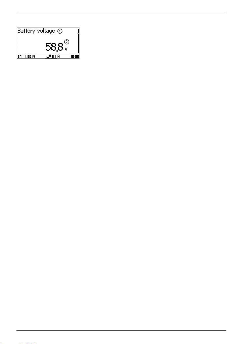
Measurements
①
Measurement name
②
Measurement with units
The following measurements are displayed in the same sequence as
described here:
n Charge current MPPT: The current flowing from the controller to
the battery, in Amperes.
n Battery voltage: The battery voltage measured at connection
"B+/B–", in volts (V).
n Voltage ext. bat. sense 1): Battery voltage measured via the
battery voltage sensor cable, in volts (V).
n SOC (MPPT 6000-M only): Charge state of the battery in %
(displayed only when the battery setting ‘Battery control mode
è State of charge (SOC)
’ is active.
n Result of capacity test (MPPT 6000-M only) 2): Result of a
manually started battery capacity test. Measured value displayed
in Ah.
n PV 1 voltage: Voltage present at module connection M1, in volts
(V).
n PV 2 voltage: Voltage present at module connection M2, in volts
(V).
n PV power total: Actual power being used for charging the
battery, measured at the module connections M1 and M2 , in
watts (W).
n PV power 1: Actual charging power at module connection M1,
in watts (W).
n PV power 2: Actual charging power at module connection M2,
in watts (W).
n Operating hours: Number of operating hours since initial
commissioning of the device.
n Power information from additional StecaLink slave participants
(MPPT 6000-M only): The scope and designations of the display
depend on the respective slave device and its configuration.
Observe the notes on this in
Ä
Chapter 8.8 ‘StecaLink bus’
on page 85.
n Total battery charge/discharge current (MPPT 6000-M only):
Total current of all components activated in the menu
‘Battery settings è Battery control mode
è Sensor member list’. Display of the average current in A.
n Total battery discharge current (MPPT 6000-M only): Total
battery discharge current of all components activated in the
menu ‘Battery settings è Battery control mode
è Sensor member list’. Display of the average current in A.
n Total battery charge/discharge power (MPPT 6000-M only): Total
power of all components activated in the menu ‘Battery settings
è Battery control mode è Sensor member list’. Display of the
average power in W.
54
756.404 | Z01 | 16.06
Page 55

n Total battery charge current (MPPT 6000-M only): Total battery
charge current of all components activated in the menu
‘Battery settings è Battery control mode
è Sensor member list’. Display of the average current in A.
1 )
"-" is displayed instead of the battery voltage when the battery
voltage sensor cable is not connected.
2)
"-" is displayed while the capacity test is running or has not yet
been executed. The result of a successfully completed capacity test is
retained until successful completion of the next capacity test. The
result of the capacity test is deleted if the device is disconnected
from the power supply.
Measurement display for additional StecaLink slave devices
①
Identifier of the StecaLink slave device.
②
StecaLink bus address of the device.
③
Device name assigned by the user.
④
Measuring position of the device.
⑤
Measured current, average value in A.
NOTICE!
The controller is not approved as a calibrated measuring device.
The displayed measurements and internally calculated values are subject to product-specific
tolerances and can therefore deviate from reference measurements made using calibrated
measuring instruments. Not all measurements and the values calculated from these are
updated in the same time frame. This can result in delayed updating of the displayed values.
Information bar
756.404 | Z01 | 16.06
①
Date
②
Symbol for Non-confirmed event messages; see Ä Chapter
10.2 ‘Event messages’ on page 111 for more information.
③
Connect symbol with 2-digit controller address: Indicates data
traffic on the StecaLink slave bus connection.
④
Symbol for the charging function presently being executed:
E (Equal charge)
F (Float charge)
B (Boost charge)
55
Page 56
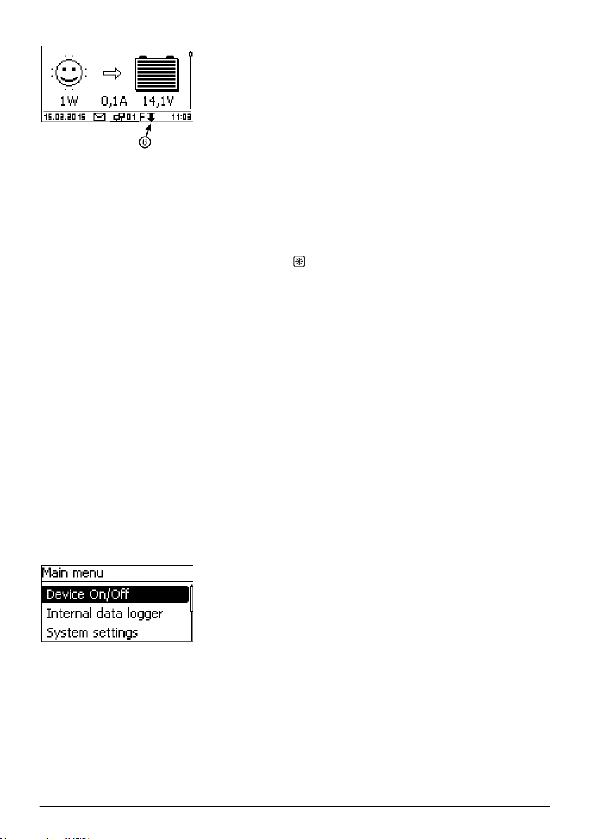
Additional symbols used in the MPPT 6000-M
I (IUIA charge)
C (Capacity test running)
L (Li-Ion charge mode)
A (NiCd charge mode)
Additional symbols used in the MPPT 6000-S
S (StecaLink slave mode active)
⑤
Time
⑥
Derating symbol. Active when the device automatically reduces
the output power due to overloading.
7.4 Display of special states
n When the inverter is processing large amounts of data it is not able to process any user input.
This is indicated by an animated sun symbol:
n The backlight blinks red when faults occur. An event message is also displayed. More
information on this is provided in
Ä
Chapter 10.2 ‘Event messages’ on page 111.
7.5 General operation
Paging through displays and menu levels
1. If necessary, press ESC for 1 s to show the basic setting of the
3. Press SET. The main menu appears and the top entry is
status display.
2.
Press D, Ñ to display the measurements.
selected.
4.
Press D, Ñ to select a different entry.
5. Press SET. The submenu appears.
6. Repeat steps 4 and 5 if necessary.
7. Press ESC briefly to jump one menu level higher or press ESC
for a longer time (1 s) to show the basic settings of the status
display.
7.6 Advanced operation
Switching the device on/off
56
✔
1.
2. Press SET. Charging of the battery is switched on/off. OFF is
‘Main menu è Device On/Off
Press D, Ñ to select On or Off.
displayed in the basic setting of the status display when
charging is switched off.
’
756.404 | Z01 | 16.06
Page 57
Displaying advanced information
MPPT 6000-M:
For the Remote setting, see Ä Chapter 6.3 ‘AUX IO remote
control input connection (MPPT 6000-M only)’ on page 41.
MPPT 6000-S:
Ä
For the Redundancy setting, see
Chapter 6.8 ‘Redundancy
function (MPPT 6000-S only)’ on page 51.
✔
‘Main menu è Information
1.
Press D, Ñ to select an entry (Fig. left).
’
2. Press SET to open the entry.
The entries contain the following information:
n Contact details
(Fig. left): The manufacturer's address
as text and QR code.
n System info (Fig. left):
– Product designation
– Serial number
– Version of the software module
– Address of the controller on the StecaLink slave bus
– Version of the operating instructions for the inverter
Calling up the expert menu for battery settings
CAUTION!
Risk of damaging the system. The expert menu allows modification of settings that require
specialist technical knowledge. The expert menu must therefore only be used by professional
personnel who know the applicable regulations and standards.
NOTICE!
The availability and scope of the settings in the expert menu depends on the currently selected
battery type (not available for Li-Ion batteries), see
Ä
Chapter 3.4 ‘Menu structure’ on page 17
and the configuration of the system functions for the selectable battery types.
756.404 | Z01 | 16.06
57
Page 58

7.7 Display settings
Contrast setting
✔
‘Main menu è Battery settings è Expert menu’
1. Press SET. The password entry dialogue appears, the
1st character from the left is selected (Fig. left).
NOTICE
The password is 17038.
2. Press SET.
3.
Set a value of ‘1’ using D, Ñ and then confirm with SET.
4.
Press Ñ to select the 2nd character from the left.
5. Press SET.
6.
Set a value of ‘7’ using D, Ñ and then confirm with SET.
7. Repeat steps 4 to 6 for the other digits.
8. Press SET for 1 s. The expert menu appears (Fig. left).
9.
Press D, Ñ to select an entry.
10. Press SET to open the entry.
✔
‘Main menu è System settings è Display settings è Contrast
1. Press SET. The Display settings dialogue appears (Fig.
left).
2. Press SET. The Contrast dialogue appears (Fig. left).
3.
Press D, Ñ to change the value.
4. Press SET. The value stops blinking.
’
Backlight settings
NOTICES
n Off: Backlight permanently deactivated.
n Auto: The backlight is activated when any key is pressed
and switches off automatically after 30 s.
n Power mode: The backlight is activated at reduced
brightness when the device is supplying power. The
backlight is switched off when the device is not supplying
power, e.g. at night.
✔
‘Main menu è System settings è Display settings
è Backlight’
1. Press SET. The Backlight mode dialogue appears (Fig. left).
2.
Press D, Ñ to select a setting.
3. Press SET. The selected mode is set.
58
756.404 | Z01 | 16.06
Page 59

8 System functions
Topics
1.
Ä
Chapter 8.1 ‘Protection functions’ on page 59
2.
Ä
Chapter 8.2 ‘Battery type setting’ on page 60
3.
Ä
Chapter 8.3 ‘Current limit system setting (MPPT 6000-M only)’ on page 60
4.
Ä
Chapter 8.4 ‘Current limit device setting’ on page 61
5.
Ä
Chapter 8.5 ‘Lead-acid battery system functions’ on page 62
6.
Ä
Chapter 8.6 ‘Li-Ion battery system functions (MPPT 6000-M only)’ on page 74
7.
Ä
Chapter 8.7 ‘NiCd battery system functions (MPPT 6000-M only)’ on page 77
8.
Ä
Chapter 8.8 ‘StecaLink bus’ on page 85
9.
Ä
Chapter 8.9 ‘Internal data logger’ on page 91
10.
Ä
Chapter 8.10 ‘Clear log data’ on page 99
11.
Ä
Chapter 8.11 ‘Clear event log’ on page 99
12.
Ä
Chapter 8.12 ‘Factory settings’ on page 99
13.
Ä
Chapter 8.13 ‘UART/RS-232 interface (MPPT 6000-M only)’ on page 100
14.
Ä
Chapter 8.14 ‘Acoustic alarm’ on page 100
15.
Ä
Chapter 8.15 ‘SD card (MPPT 6000-M only)’ on page 101
8.1 Protection functions
8.1.1 Controller overload
The controller is protected from the following faults and is not damaged when these faults only
occur individually:
n Solar module or battery connected with the wrong polarity.
n Solar module or battery not connected with the wrong polarity but connected to the wrong
connection.
n Solar modules are short-circuited (charging is switched off (OFF); charging cannot be switched
on if a short-circuit is detected).
n Battery is not connected.
Once the individual fault has been corrected the controller will operate correctly without taking any
further measures.
CAUTION!
The following faults damage the controller:
A solar module is connected to multiple controllers in parallel.
–
– The solar modules are short-circuited while the device is charging.
756.404 | Z01 | 16.06
59
Page 60

NOTICE!
The controller responds to different battery voltages in the following different ways:
Battery voltage below 9.5 VDC: Safe and reliable operation is no longer guaranteed. The
–
controller stops all functions, especially charging of the battery.
– Battery voltage between 9.5 VDC and 10.0 VDC: The device responds to operating
commands and the display functions correctly.
– Battery voltage above 10,0 VDC: The batteries are charged. Normal operation of the
device.
8.1.2 Overheating of the controller
The cooling ribs on the rear side and the internal temperature controller prevent the controller from
overheating. If the controller still becomes too hot it reduces the charging of the battery stepwise
(derating) and stops charging completely if necessary (power unit switched off). Charging of the
battery is automatically resumed after the device has cooled down.
8.1.3
The relay outputs AUX 1/2/3 can be used to protect the battery from becoming deeply discharged.
For more information see
on page 41.
Deep discharging of the battery (MPPT 6000-M only)
Ä
Chapter 6.2 ‘AUX 1,2,3 relay output connection (MPPT 6000-M only)’
8.2 Battery type setting
CAUTION!
Different settings and charging parameters are possible depending on the battery type that is
set.
Selecting the wrong battery type can permanently damage the existing battery.
Ä
For settings see .
the battery type’ on page 35.
Chapter 5 ‘Initial commissioning of the base system’ on page 33▶ Ä ‘Set
8.3 Current limit system setting (MPPT 6000-M only)
NOTICE!
In a StecaLink master/slave network the MPPT 6000-M can control the total charge current of
all MPPT 6000-S and MPPT 6000-M in the network.
The configured maximum system charge current is dynamically distributed across all the MPPT
6000-M and MPPT 6000-S power units.
The local Current limit device setting of the device is taken into account in determining the
distribution.
The actual charge current of the devices is taken into consideration for the distribution.
Usage of the local Current limit device setting can be switched on and off.
60
756.404 | Z01 | 16.06
Page 61

Current limit system: On/Off
Current limit system: Value
✔
‘Main menu è Battery settings è Current limit system’
1. Press SET. The Current limit system menu appears (Fig.
left).
2.
Press D, Ñ to select the menu item On/Off.
3. Press SET. The Current limit system dialogue appears
(Fig. left).
4.
Press D, Ñ to select On/Off.
5. Press SET. Control of the maximum system charge current is
switched on or off accordingly.
✔
‘Main menu è Battery settings è Current limit system
’
1. Press SET. The Current limit system menu appears (Fig.
left).
2.
Press D, Ñ to select the menu item Value.
3. Press SET. The Current limit system dialogue appears
(Fig. left).
4. Press SET. The value flashes.
5.
Press D, Ñ to change the value.
6. Press SET. The value stops blinking.
8.4 Current limit device setting
NOTICE!
It may be necessary to limit the maximum charge current used for charging the battery. The
specifications and notes of the battery manufacturer must be adhered to. Take care to observe
the specifications of the battery management system (BMS) when using Li-Ion batteries. This
limit is set to the maximum possible current of 60 A in newly delivered MPPT 6000-M and MPPT
6000-S devices.
756.404 | Z01 | 16.06
61
Page 62

Current limit device: Value
✔
‘Main menu è Battery settings è Current limit device’
1. Press SET. The dialogue Device current limit appears
(Fig. left).
2. Press SET. The value flashes.
3.
Press D, Ñ to change the value.
4. Press SET. The value stops blinking.
8.5 Lead-acid battery system functions
8.5.1
Deactivating/activating cyclic equalisation charging
Equalisation cycle mode
NOTICE!
Cyclic equalisation charging settings are only available for the lead-acid battery type. These
settings allow activation/deactivation of cyclic equalisation charging and configuration of a
fixed duration between each cyclic equalisation charging process.
✔
‘Main menu è Battery settings è Equalisation cycle mode
è On/Off’
1. Press SET. The Equalisation cycle mode dialogue appears
(Fig. left).
2.
Press D, Ñ to select On or Off.
3. Press SET. Cyclic equalisation charging is switched on or off
accordingly.
Cycle duration
62
✔
‘Main menu è Battery settings è Equalisation cycle è Cycle’
1. Press SET. The Equalisation cycle dialogue appears (Fig.
left).
2. Press SET. The value flashes.
3.
Press D, Ñ to change the value.
4. Press SET. The value stops blinking.
756.404 | Z01 | 16.06
Page 63

8.5.2 Battery control mode (MPPT 6000-M only)
NOTICE!
– The state of charge (SOC) mode or voltage control mode can be selected for lead-acid or
lead-gel/AGM battery types.
Voltage control is the predefined fixed mode for Li-Ion and NiCd battery types.
–
– The State of charge (SOC) control mode activates calculation of the state of charge
of the battery. This calculated SOC value is shown in the status display and the
measurements, see
– In the State of charge (SOC) control mode, the calculated state of charge controls
execution of the following functions:
– Deep discharge protection
– Excess energy control
– Generator control
See
Ä
Chapter 9 ‘Control functions via AUX 1/2/3 (MPPT 6000-M only)’ on page 103.
– This also controls activation of the following charge modes:
– Boost charging
– Equalisation charging
See
Ä
Chapter 8.5.8 ‘Charge voltages’ on page 66.
– In the voltage control mode, the actual battery voltage controls execution of the
following functions:
– Deep discharge protection
– Excess energy control
– Generator control
See
Ä
Chapter 9 ‘Control functions via AUX 1/2/3 (MPPT 6000-M only)’ on page 103.
– The actual battery voltage also controls activation of the following charge modes:
– Boost charging
– Equalisation charging
See
Ä
Chapter 8.5.8 ‘Charge voltages’ on page 66.
– Using the state of charge (SOC) control mode only makes sense when all battery charge
and discharge currents can be measured by the MPPT 6000-M. Additional PA HS400
current sensors are required for measuring the discharge currents. Additional external PA
HS400 current sensors are also required for measuring charge currents that do not flow
through the MPPT 6000-M or through MPPT 6000-S devices in the master/slave network.
– No additional current sensors are required when using the voltage control mode.
– If the discharge depth is to be taken into consideration for adjusting the upper charge
voltage U1 when charging NiCd batteries then the discharge current must be measured by
external PA HS400 current sensors. The necessary sensors must be activated via the
Sensor member list menu item.
– All devices to be used for calculating the total battery current must be specified in the
Sensor member list menu item. The total of all currents selected here is used for
calculating the state of charge and is displayed in the Total charge/discharge
current of battery field of the status display, see
on page 53.
Ä
Chapter 7.3 ‘Status display’ on page 53.
Ä
Chapter 7.3 ‘Status display’
756.404 | Z01 | 16.06
63
Page 64

SOC Control mode
Sensor member list
✔
‘Main menu è Battery settings è Battery è control mode
è SOC control mode ’
1. Press SET. The SOC Control mode dialogue appears (Fig.
left).
2.
Press D, Ñ to change the control mode.
3. Press SET. The selected control mode is marked and adopted.
✔
‘Main menu è Battery settings è Battery è control mode
è Sensor member list
’
1. Press SET. The Sensor member list dialogue appears (Fig.
left).
2.
Press D, Ñ to select the members.
3. Press SET. The selected member is marked and adopted.
Repeat the selection process until all members relevant for
determining the total battery charge/discharge current are
selected.
64
756.404 | Z01 | 16.06
Page 65

8.5.3 Battery capacity test (MPPT 6000-M only)
NOTICE!
– The capacity test function is only available for lead-acid and lead-gel/AGM battery types.
The capacity test allows the controller to measure the usable capacity of the battery while
–
it is being discharged by the connected loads.
– The measured value is displayed as the Result of capacity test measurement in the
status window, see
– During the capacity test, the battery is not charged by the MPPT 6000-M or any other
MPPT 6000-S devices controlled via the StecaLink bus. The device enters the OFF state.
– After completion of the capacity test, charging must be manually started via the MPPT
6000-M. ‘Main menu è Device On/Off è On’.
– The following conditions must be satisfied in order to execute the capacity test:
– The nominal capacity of the battery must be set. The nominal capacity is usually
specified on the battery type plate.
– A PA HS400 external current sensor must be installed and registered at the MPPT
6000-M in order to measure the charge currents. The external current sensor must be
selected via ‘Main menu è Battery settings è Battery control mode
è Sensor member list’.
– The external battery temperature sensor must be installed and activated, see
Ä
Chapter 6.4 ‘PA TS-S external temperature sensor connection’ on page 43.
– The generator control function must be manually disabled. Charging from external
sources must be ruled out during execution of the capacity test.
– The external control function via the AUX IO connection must be disabled in order to
use the capacity test.
– The battery must be discharged by the "loads" connected to the system. The controller
deep discharge protection via the AUX 1/2/3 outputs is active during the test.
– The necessary conditions must be established before starting the capacity test. Changes
made after starting the test will cancel the test. The test must then be started anew.
– The capacity test almost completely discharges the battery. This can result in the battery
being discharged below the configured deep discharge protection threshold. Only the
consumers controlled via the AUX 1/2/3 outputs can be automatically switched off to
prevent deep discharging of the battery. The capacity test is cancelled without a result if
the deep discharge protection function of the MPPT 6000-M prevents the discharging
required for completing the capacity test.
– Switching the device on/off cancels the capacity test.
– Execution of the capacity test can take several hours or even days, depending on the
battery size and condition and the discharge current of the available loads. For a sensible
execution, the average discharge current of the loads should approximately correspond to
the 10-hour discharge current. A changing load profile is beneficial for the capacity test.
– Execute the capacity test only if the system must not continuously supply energy. It might
not be possible to supply the loads with energy during the necessary subsequent battery
recharging period.
– Ensure a prompt and full recharging of the battery after finishing a capacity test. Be aware
of the the fact that poor weather conditions can restrict the performance of the PV system.
Ä
Chapter 7.3 ‘Status display’ on page 53.
756.404 | Z01 | 16.06
65
Page 66

Battery capacity test
✔
‘Main menu è Battery settings è Battery capacity test ’
1. Press SET. The Start capacity test dialogue appears (Fig.
left).
2. Press and hold SET for 1 s. The capacity test starts.
3. The display switches to the Battery settings menu.
If the capacity test could be successfully started then charging
is deactivated (OFF) and the code C
the status screen, see
on page 53.
Ä
Chapter 7.3 ‘Status display’
is displayed in the footer of
8.5.4 Battery type
For information on switching between the lead-acid, lead-gel/AGM, Li-Ion and NiCd battery
types, see
Ä
Chapter 5 ‘Initial commissioning of the base system’ on page 33.
8.5.5 Battery capacity
For the battery capacity settings see
on page 33.
Ä
Chapter 5 ‘Initial commissioning of the base system’
8.5.6 Current limit system (MPPT 6000-M only)
Ä
For the current limit system setting, see
6000-M only)’ on page 60.
Chapter 8.3 ‘Current limit system setting (MPPT
8.5.7 Current limit device
Ä
For the current limit device setting, see
on page 61.
Chapter 8.4 ‘Current limit device setting’
8.5.8 Charge voltages
CAUTION!
Ensure that the charge limit settings agree with the specifications of your battery. Incorrect
settings can destroy the battery.
66
756.404 | Z01 | 16.06
Page 67
Float charging
✔
‘Main menu è Battery settings è Charge voltages
è Float charging’
1. Press SET. The Float charging dialogue appears (Fig. left).
2. Press SET. The Float charge voltage value flashes.
3.
Press D, Ñ to change the value.
4. Press SET. The value stops blinking.
Boost charging
NOTICES
n If the State of charge (SOC) control mode is selected
then the starting threshold is specified as %-SOC.
n If the Voltage control control mode is selected then
the starting threshold is specified as V.
✔
‘Main menu è Battery settings è Charge voltages
è Boost charging’
1. Press SET. The Boost charging dialogue appears (Fig. left).
2. Press SET. The Starting threshold value flashes.
3.
Press D, Ñ to change the value.
4. Press SET. The value stops blinking.
5.
Press Ñ to select Boost charge voltage.
6. Press SET. The Boost charge voltage value flashes.
7.
Press D, Ñ to change the value.
8. Press SET. The value stops blinking.
Equalisation charging
NOTICES
n This setting is only possible for the lead-acid battery type.
n If the State of charge (SOC) control mode is selected
then the starting threshold is specified as %-SOC.
n If the Voltage control control mode is selected then
the starting threshold is specified as V.
✔
‘Main menu è Battery settings è Charge voltages
è Equalisation charging
1. Press SET. The Equalisation charging dialogue appears
(Fig. left).
2. Press SET. The Starting threshold value blinks.
3.
Press D, Ñ to change the value.
4. Press SET. The value stops blinking.
756.404 | Z01 | 16.06
’
67
Page 68

5.
Press Ñ to select Equal. charge voltage.
6. Press SET. The Equal. charge voltage value blinks.
7.
Press D, Ñ to change the value.
8. Press SET. The value stops blinking.
68
756.404 | Z01 | 16.06
Page 69

8.5.9 IUIA charge mode (MPPT 6000-M only)
CAUTION!
IUIA charging performs targeted overcharging of the battery. This can result in voltages of up
to 2.6 V/cell. All loads connected to the battery must be able to tolerate these higher voltages,
even when these are only in Standby mode.
NOTICE!
– The IUIA charge mode is only available for lead-acid and lead-gel/AGM battery types.
The IUIA charge mode can be activated for these battery types in the menu. The IUIA
–
charge mode is executed repeatedly according to a configurable 1-6 monthly cycle.
– The first execution of the IUIA charge mode after it has been activated only occurs after
completion of the first boost charging subsequent to the time of activation. The repetition
cycle is based on the month of first execution. The repetition cycle is not accurate to the
day. The IUIA charging mode is executed after completion of the first boost charging
during the active month for the repetition cycle.
– Execution of equalisation charging never activates the IUIA charge mode. Repeat execution
of a boost charge during the repetition cycle does not cause premature execution of IUIA
charging.
– An active IUIA charge mode is cancelled when the device is switched off, state Off.
– The following conditions must be satisfied in order to execute the IUIA charge mode:
– The nominal capacity of the battery must be set. The nominal capacity is usually
specified on the battery type plate. The battery capacity specification is used for
determining the I50 charge current. I50 = Ah/50h.
– The battery used must have a minimum capacity of 50 Ah.
– Energy loads connected to the battery must be regulated so that the battery charge
current can drop to I50. Loads must be disconnected if necessary.
– The MPPT 6000-M regulates its power unit charge current to I50. Regulation of external
currents, that can be e.g monitored with PA HS400 current sensors is not performed.
– In the IUIA charge mode, the capacity counting is performed according to the selections
made in ‘Main menu è Battery settings è Battery control mode è Sensor member list’.
– The IUIA consists of three phases:
– I phase: The I phase corresponds to charging the battery using the boost charging
settings. After the period configured for boost charging expires the state changes to
the U phase.
– U phase: In the U phase charging continues with a voltage of 2.4 V/cell until the
charge current is less than I50 of the battery for at least 50 s. The IUIA charging stops
if more than 40 % of the specified battery capacity is charged in the period until the
charge current drops to I50. The device then switches to the Float charging mode. If a
voltage of 2.4 V/cell cannot be maintained during the U phase due to insufficient
charging power then the device remains in the U phase but the capacity counter is
stopped. The capacity counter is started again when the charging power is sufficient
for maintaining a voltage of 2.4 V/cell.
– IA phase: The charge current is limited to I50 during the IA phase. An active IA phase
is indicated by the letter I in the footer of the status display, see
display’ on page 53 . When the battery voltage reaches the range of 2.53 V/cell to
2.55 V/cell the amount of charged energy is now measured using a capacity counter.
The IA phase ends when the battery is charged to 20 % of the specified nominal
battery capacity. This ends the entire IUIA charging cycle and the MPPT 6000-M
Ä
Chapter 7.3 ‘Status
756.404 | Z01 | 16.06
69
Page 70
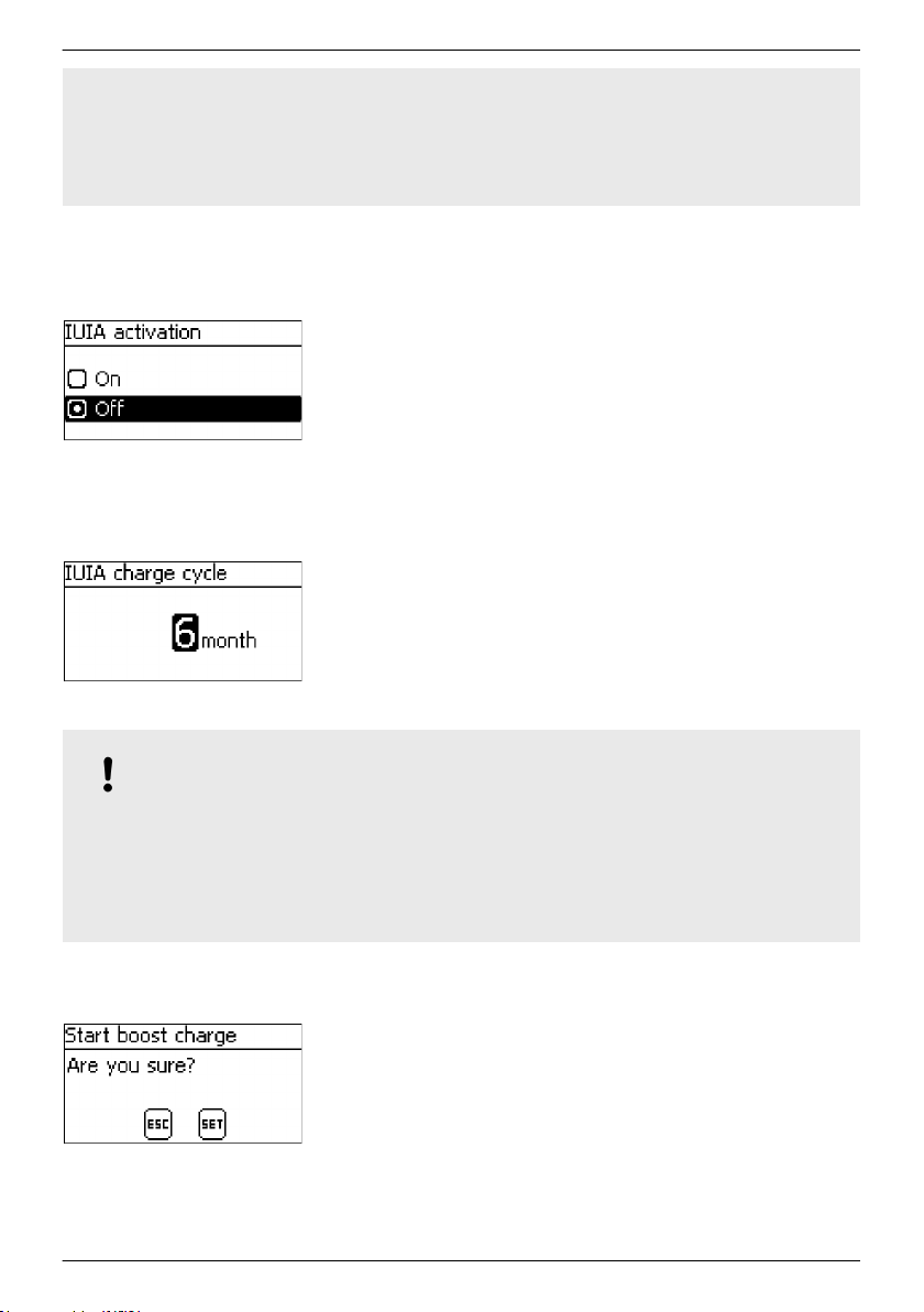
switches to the Float charging mode. If the battery voltage cannot be maintained at
>2.53 V/cell for longer than 120 s during the the IA phase then the IA is ended and
the sequence starts again in the I phase. If the battery voltage reaches a value >=
2.6 V/cell during the IA phase then the MPPT 6000-M switches off the charging. The
device enters the OFF
IUIA charge mode On/Off
IUIA charge mode Cycle
state. This ends the IUIA charging cycle.
✔
‘Main menu è Battery settings è IUIA activation è On/Off ’
1. Press SET. The IUIA activation dialogue appears (Fig. left).
2.
Press D, Ñ to change the value.
3. Press SET. The value is adopted.
✔
‘Main menu è Battery settings è IUIA charge mode è Cycle ’
1. Press SET. The IUIA charge cycle dialogue appears (Fig.
left).
2.
Press D, Ñ to change the value.
3. Press SET. The value stops blinking.
8.5.10 Start boost charge
NOTICE!
– Start boost charge
– The boost charging is executed using the previously configured parameters.
– The device switches to float charging on completion of boost charging.
– This function is only available for lead-acid and lead-gel/AGM battery types.
– Once started, boost charging can only be stopped by switching the device off (OFF).
70
allows boost charging to be started manually.
✔
‘Main menu è Battery settings è Start boost charge’
1. Press SET. The Start boost charge dialogue appears. (Fig.
left).
2. Press SET for 1 s to start the boost charge.
756.404 | Z01 | 16.06
Page 71
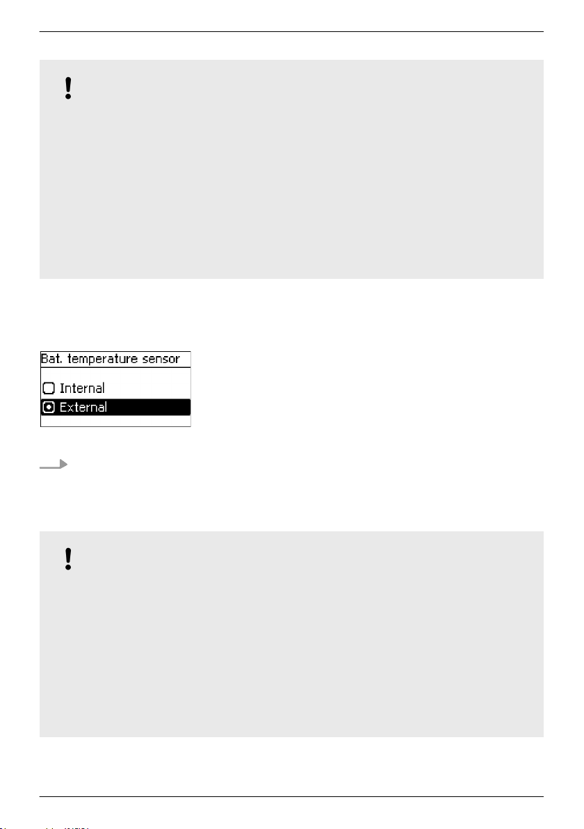
8.5.11 Battery temperature sensor
NOTICE!
Ä
– Observe the notices on connecting the external temperature sensor in
TS-S external temperature sensor connection’ on page 43.
– The MPPT 6000-M/MPPT 6000-S devices have a function allowing automatic temperature
compensation of the end-of-charge voltage used for charging.
– The device must measure the ambient temperature of the battery in order to use this
function. The internal temperature sensor can be used if the battery and device are in the
same temperature area. An external temperature sensor must be used if the battery and
device are in different temperature areas.
– We recommend always using the external temperature sensor because this provides more
accurate temperature measurements.
– The external temperature sensor must be correctly connected if it is selected as the source.
Otherwise an Error event message is generated.
Battery temperature sensor
✔
‘Main menu è Battery settings è Bat. temperature sensor
1. Press SET. The Bat. temperature sensor dialogue appears
(Fig. left).
2.
Press D, Ñ to change the selection.
3. Press SET. The selection stops blinking and is adopted.
Chapter 6.4 ‘PA
’
8.5.12 Cable compensation
For the cable compensation settings, see
system’ on page 33.
Ä
Chapter 5 ‘Initial commissioning of the base
8.5.13 PV string connection
NOTICE!
– Observe the technical data of the device when designing and connecting the PV string
inputs.
– The device is capable of performing separate power control and MPP tracking for each PV
string input. This requires both PV string inputs to be electrically isolated from each other.
Separate use of the strings is recommended.
– The ‘separated’ setting must be selected for separate inputs, otherwise the power yield
for battery charging is reduced. The default setting is ‘separated’ .
– If a suitable division of the PV generator across the two PV strings is not possible then
parallel connection can be used.
– In addition to the necessary changes in the menu, this also requires the "M1–"/"M2–" and
"M1+"/"M2+" connections to be electrically wired in parallel (bridged).
756.404 | Z01 | 16.06
71
Page 72
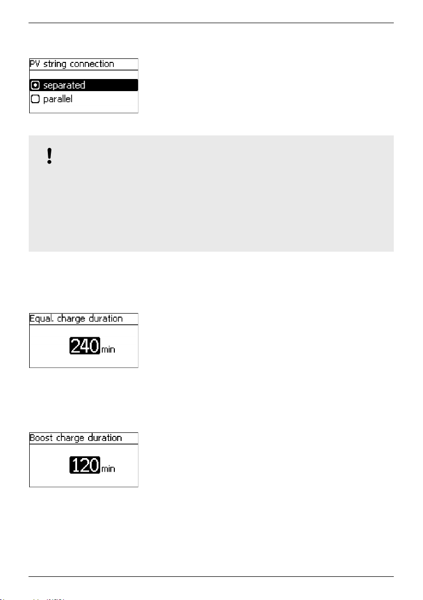
PV string connection
✔
‘Main menu è Battery settings è PV string connection ’
1. Press SET. The PV string connection dialogue appears
(Fig. left).
2.
Press D, Ñ to change the selection.
3. Press SET. The selection stops blinking and is adopted.
8.5.14 Expert menu
NOTICE!
Ä
– For information on accessing this menu, see
on page 56.
– For lead-acid batteries, the expert menu allows configuration of the following parameters:
– duration of boost charging and equalisation charging,
– switching the temperature compensation on/off,
– changing the factors used for temperature compensation and
– system voltage.
Equalise charge duration
✔
‘Main menu è Battery settings è Expert menu
è 17038 [SET] 1s è Equal. charge duration
1. Press SET. The Equal. charge duration
(Fig. left).
2. Press SET. The value flashes.
3.
Press D, Ñ to change the value.
4. Press SET. The value stops blinking.
Chapter 7.6 ‘Advanced operation’
’
dialogue appears
Boost charge duration
✔
‘Main menu è Battery settings è Expert menu
è 17038 [SET] 1s è Boost charge duration
1. Press SET. The Boost charge duration dialogue appears
(Fig. left).
2. Press SET. The value flashes.
3.
Press D, Ñ to change the value.
4. Press SET. The value stops blinking.
72
’
756.404 | Z01 | 16.06
Page 73
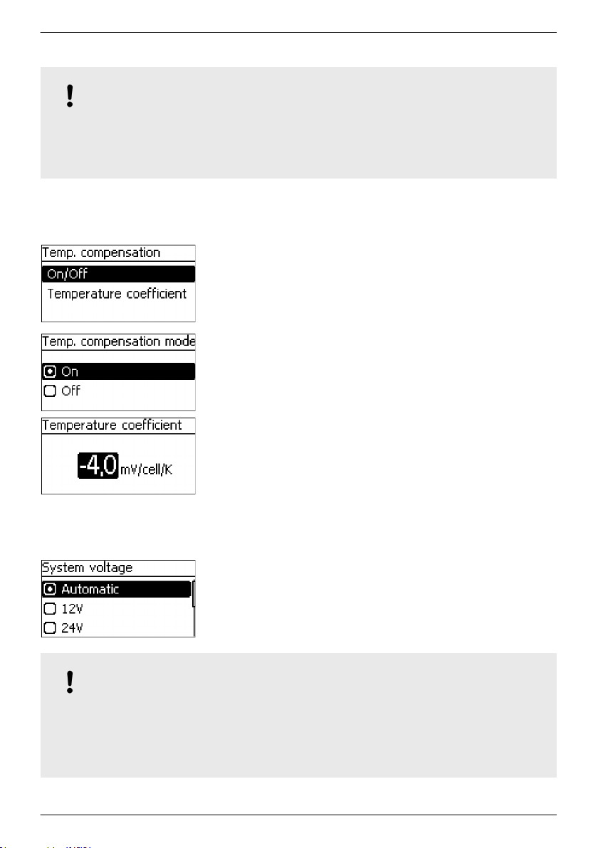
Temperature compensation
NOTICE!
The temperature compensation offsets the charge cut-off voltage by the specified value per
battery cell (2 V cells in lead-acid batteries) and per degree Kelvin. For example, a temperature
coefficient of -4,0 mV/cell/K for a 48 V lead-acid battery causes the charge cut-off voltage to be
offset by -96 mV per degree Kelvin temperature difference relative to 25 °C.
System voltage
✔
‘Main menu è Battery settings è Expert menu
è 17038 [SET] 1s è Temp. compensation
’
1. Press SET. The Temp. compensation dialogue appears (Fig.
left).
2.
Press D, Ñ to change the selection.
3. Select On/Off and press SET. The Temp. compensation
mode dialogue appears.
4.
Press D, Ñ to change the selection.
5. Press SET. The selection is adopted.
6. Press ESC to exit the selection dialogue.
7.
Press D, Ñ to change the selection.
8. Select Temperature coefficient and press SET. The
Temperature coefficient dialogue appears.
9. Press SET. The value flashes.
10.
Press D, Ñ to change the value.
11. Press SET. The value stops blinking and is adopted.
✔
‘Main menu è Battery settings è Expert menu
è 17038 [SET] 1s è System voltage
’
1. Press SET. The System voltage dialogue appears (Fig. left).
2.
Press D, Ñ to change the selection.
3. Press SET. The selection is adopted.
NOTICE!
For lead-acid batteries, the system voltage always relates to the nominal voltage of the battery.
The device is configured for automatic voltage detection at the factory. This allows automatic
detection of the voltage levels 12 V, 24 V and 48 V. The system voltage must be directly
selected if the controller is to be used with system voltages of 36 V or 60 V. The system voltage
setting defines various other preset values and setting ranges.
756.404 | Z01 | 16.06
73
Page 74

CAUTION!
Check the correct system voltage before changing the system voltage setting and check all
device settings immediately after changing the system voltage setting. Incorrect settings can
damage the battery.
8.6 Li-Ion battery system functions (MPPT 6000-M only)
NOTICE!
– Ensure that all settings agree with the specifications provided by the manufacturer of the
Li-Ion battery. The initial default settings provided are not recommendations.
Observe the safety notices for the battery used.
–
– The scope of the Battery settings menu changes when the Li-Ion battery type is selected.
– When the Li-Ion battery type is selected, the possible settings for the following functions
assigned to the AUX 1/2/3 outputs also change:
– deep discharge protection,
– generator control,
– excess energy control.
8.6.1 Battery control mode
NOTICE!
For the Li-Ion battery type, the measurement sources to be used for determining the total
battery charge/discharge current are defined via the Battery control mode menu.
Ä
For the sensor member list settings, see
M only)’ on page 63.
Chapter 8.5.2 ‘Battery control mode (MPPT 6000-
8.6.2 Battery type
For information on switching between the lead-acid, lead-gel/AGM, Li-Ion and NiCd battery
types, see
Ä
Chapter 5 ‘Initial commissioning of the base system’ on page 33.
8.6.3 Battery capacity
For the battery capacity settings see Ä Chapter 5 ‘Initial commissioning of the base system’
on page 33.
8.6.4 Current limit system
For the current limit system setting, see
6000-M only)’ on page 60.
74
Ä
Chapter 8.3 ‘Current limit system setting (MPPT
756.404 | Z01 | 16.06
Page 75

8.6.5 Current limit device
For the current limit device setting, see Ä Chapter 8.4 ‘Current limit device setting’
on page 61.
8.6.6 Li-Ion battery settings
Prerequisite
✔‘Main menu è Battery settings è Battery type è Li-Ion battery
Number of cells
NOTICE
The number of Li-Ion cells connected in series.
‘Main menu è Battery settings è Li-Ion battery settings
è Number of cells’
1. Press SET. The Number of Li-Ion cells
(Fig. left).
2. Press SET. The value flashes.
3.
Press D, Ñ to change the value.
4. Press SET. The value stops blinking.
Cell voltage
✔
‘Main menu è Battery settings è Li-Ion battery settings
è Cell voltage’
1. Press SET. The Li-Ion cell voltage dialogue appears (Fig.
left).
2. Press SET. The value flashes.
3.
Press D, Ñ to change the value.
4. Press SET. The value stops blinking.
’
dialogue appears
Charge voltage
756.404 | Z01 | 16.06
✔
‘Main menu è Battery settings è Li-Ion battery settings
è Charge voltage’
1. Press SET. The Li-Ion charge voltage dialogue appears
(Fig. left).
2. Press SET. The value flashes.
3.
Press D, Ñ to change the value.
4. Press SET. The value stops blinking.
75
Page 76

Charge activation
NOTICE
Voltage threshold of the individual Li-Ion cell, below which
charging by the MPPT 6000-M is activated. Charging is not
started if the cell voltage does not drop below the charge
activation value.
✔
‘Main menu è Battery settings è Li-Ion battery settings
è Charge activation’
1. Press SET. The Li-Ion charge activation dialogue
appears (Fig. left).
2. Press SET. The value flashes.
3.
Press D, Ñ to change the value.
4. Press SET. The value stops blinking.
Charge timer
NOTICES
n Period during which the MPPT 6000-M maintains the
charge voltage at the Li-Ion battery.
n When the charge timer expires, charging is stopped until
the cell voltage once more drops below the charge
activation value.
✔
‘Main menu è Battery settings è Li-Ion battery settings
è Charge timer
1. Press SET. The Li-Ion charge timer dialogue appears (Fig.
left).
2. Press SET. The value flashes.
3.
Press D, Ñ to change the value.
4. Press SET. The value stops blinking.
’
Temperature range
NOTICES
n Li-Ion batteries are only charged when they have a
temperature lying in the range specified by the minimum
and maximum temperature values.
n The MPPT 6000-M stops charging if the measured battery
temperature lies outside this range.
n The internal or external temperature sensor of the MPPT
6000-M can be used for measuring this temperature, see
Ä
on page 71. The external sensor should preferably be used
because it offers higher accuracy.
✔
‘Main menu è Battery settings è Li-Ion battery settings
è Temperature range
76
Chapter 8.5.11 ‘Battery temperature sensor’
’
756.404 | Z01 | 16.06
Page 77

1. Press SET. The Li-Ion temperature range dialogue
appears (Fig. left).
2. Press SET. The Min. temperature value flashes.
3.
Press D, Ñ to change the value.
4. Press SET. The value stops blinking.
5.
Press Ñ to select the Max. temperature value.
6. Press SET. The Max. temperature value flashes.
7.
Press D, Ñ to change the value.
8. Press SET. The value stops blinking.
8.6.7 Battery temperature sensor
NOTICE!
– For the Li-Ion battery type, the temperature sensor is used for monitoring the temperature
range configured for charging.
The charge voltage is not temperature compensated.
–
Ä
For settings see
Chapter 8.5.11 ‘Battery temperature sensor’ on page 71.
8.6.8 Cable compensation
Ä
For the cable compensation settings, see
system’ on page 33.
Chapter 5 ‘Initial commissioning of the base
8.6.9 PV string connection
Ä
For settings see
Chapter 8.5.13 ‘PV string connection’ on page 71.
8.7 NiCd battery system functions (MPPT 6000-M only)
NOTICE!
– Ensure that all settings agree with the specifications provided by the manufacturer of the
NiCd battery. The initial default settings provided are not recommendations.
Observe the safety notices for the battery used.
–
– The scope of the Battery settings menu changes in comparison to the lead-acid/Li-Ion
settings when the NiCd battery type is selected.
– When the NiCd battery type is selected, the possible settings for the following functions
assigned to the AUX 1/2/3 outputs also change:
– deep discharge protection,
– generator control,
– excess energy control.
756.404 | Z01 | 16.06
77
Page 78

8.7.1 Battery control mode
For the sensor member list settings, see Ä Chapter 8.5.2 ‘Battery control mode (MPPT 6000M only)’ on page 63.
8.7.2 Battery type
For the lead-acid, lead-gel/AGM, Li-Ion, NiCd battery type settings, see
commissioning of the base system’ on page 33.
Ä
Chapter 5 ‘Initial
8.7.3 Battery capacity
For the battery capacity settings see
on page 33.
Ä
Chapter 5 ‘Initial commissioning of the base system’
8.7.4 Current limit system
Ä
For the current limit system setting, see
6000-M only)’ on page 60.
Chapter 8.3 ‘Current limit system setting (MPPT
8.7.5 Current limit device
Ä
For the current limit device setting, see
on page 61.
Chapter 8.4 ‘Current limit device setting’
78
756.404 | Z01 | 16.06
Page 79

8.7.6 NiCd battery settings
NOTICE!
– A two stage charging procedure with an upper charge voltage U1 and a lower charge
voltage U2 is used for charging NiCd batteries.
The parameter settings allow the upper charge voltage U1 to be adjusted according to the
–
actual prior discharge depth or according to an assumed fixed discharge depth. The
discharge current of the NiCd battery must be measured using one or more external PA
HS400 current sensors in order to determine the actual depth of discharge. The PA HS400
sensors used for measuring the discharge current must be registered via the
‘Battery control mode è Sensor member list’ dialogue.
– Temperature compensation of the upper charge voltage U1 can also be programmed.
Separate temperature compensation factors can be set for temperature ranges above 0 °C
and below 0 °C.
– Adjustment of the upper charge voltage U1 depending on the discharge depth and the
temperature compensation is performed up to a configurable limit for U1.
– Charging with the upper charge voltage U1 specified in the configuration is performed for
the configurable charging time U1.
– The configured charging time U1 starts counting down when the voltage of the NiCd
battery has reached the active charge voltage U1, under consideration of a configurable
tolerance threshold, and can be maintained at this value using the available charge
current.
– The charging time U1 is reset when the battery drops below a configurable discharge
depth. Charging of the NiCd battery is then restarted using the active upper charge
voltage U1.
– Charging of the NiCd battery switches to the lower charge voltage U2 after the charging
time U1.
– Separate lower charge voltage U2 temperature compensation factors can also be set for
temperature ranges above 0 °C and below 0 °C.
– In contrast to the upper charge voltage U1, the lower charge voltage U2 is not adjusted
based on the discharge depth.
– Charging at the lower charge voltage U2 continues until the battery is discharged below
the configurable U2 U1 switch voltage threshold. Charging of the NiCd battery is restarted
using the active upper charge voltage U1 when the battery drops below this threshold.
Upper charge voltage U1
NOTICE
Nominal value of the upper charge voltage in a two-stage
charging process.
‘Main menu è Battery settings è NiCd battery settings
è Upper charge voltage U1
1. Press SET. The Upper charge voltage U1 dialogue appears
(Fig. left).
2. Press SET. The value flashes.
3.
Press D, Ñ to change the value.
4. Press SET. The value stops blinking.
756.404 | Z01 | 16.06
’
79
Page 80
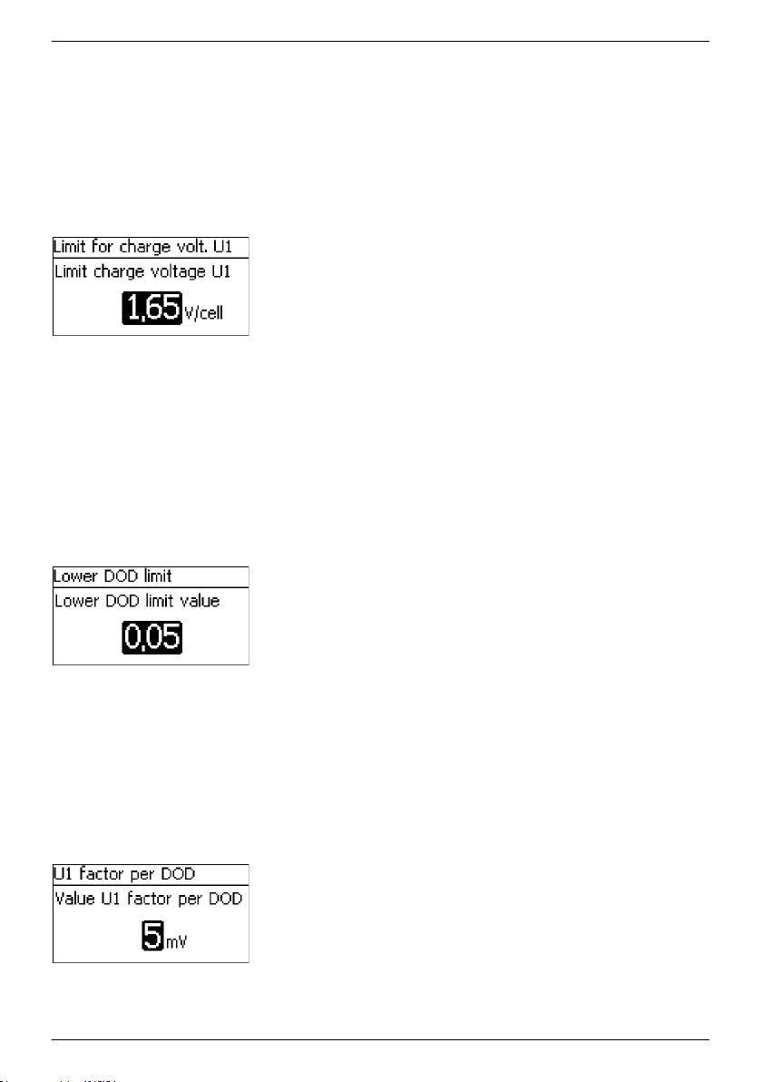
Limit for charge voltage U1
NOTICES
n Maximum value of the upper charge voltage in a two-
stage charging process.
n Automatic adjustment of the upper charge voltage U1 due
to temperature compensation and prior depth of
discharge will be limited to this maximum value.
✔
‘Main menu è Battery settings è NiCd battery settings
è Limit for charge volt. U1 U1’
1. Press SET. The Limit for charge volt. U1 dialogue
appears (Fig. left).
2. Press SET. The value flashes.
3.
Press D, Ñ to change the value.
4. Press SET. The value stops blinking.
Lower DOD limit
NOTICES
n Adjustment of the upper charge voltage U1 becomes
active when the battery drops below this depth of
discharge limit value (depth of discharge - DOD).
n A value of 0.05 means a 5 % depth of discharge relative to
the configured battery capacity.
✔
‘Main menu è Battery settings è NiCd battery settings
è Lower DOD limit’
1. Press SET. The Lower DOD limit dialogue appears (Fig. left).
2. Press SET. The value flashes.
3.
Press D, Ñ to change the value.
4. Press SET. The value stops blinking.
U1 factor per DOD
NOTICES
n Factor per 1 % DOD, by which the upper charge voltage
U1 is adjusted.
n The value is specified in mV per cell.
✔
‘Main menu è Battery settings è NiCd battery settings
è U1 factor per DOD
1. Press SET. The U1 factor per DOD dialogue appears (Fig.
left).
2. Press SET. The value flashes.
3.
Press D, Ñ to change the value.
4. Press SET. The value stops blinking.
80
’
756.404 | Z01 | 16.06
Page 81
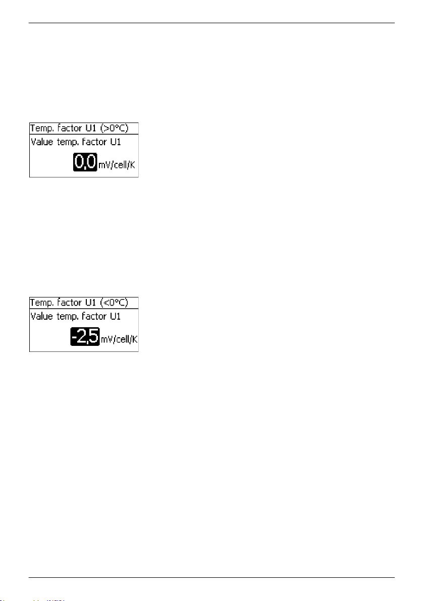
Temp. factor U1 (>0°C)
NOTICES
n Temperature compensation factor for the upper end-of-
charge voltage U1 at positive temperatures.
n Specification of the adjustment factor in mV per cell and
per degree of temperature change.
✔
‘Main menu è Battery settings è NiCd battery settings
è Temp. Factor U1 (>0°)
1. Press SET. The Temp. factor U1 (>0°C)
(Fig. left).
2. Press SET. The value flashes.
3.
Press D, Ñ to change the value.
4. Press SET. The value stops blinking.
Temp. factor U1 (<0°C)
NOTICES
n Temperature compensation factor for the upper end-of-
charge voltage U1 at negative temperatures.
n Specification of the adjustment factor in mV per cell and
per degree of temperature change.
✔
‘Main menu è Battery settings è NiCd battery settings
è Temp. Factor U1 (<0°)
1. Press SET. The Temp. factor U1 (<0°C)
(Fig. left).
2. Press SET. The value flashes.
3.
Press D, Ñ to change the value.
4. Press SET. The value stops blinking.
’
dialogue appears
’
dialogue appears
Fix DOD level
NOTICES
n Selection of whether the actual cycle depth or a fixed cycle
depth specified here is to be used for adjustment of the
upper charge voltage U1.
n With a setting of 0.00 the actual cycle depth that occurs is
used for cycle-dependent adjustment of the upper charge
voltage U1.
n A value other than 0.00 is used as a fixed value. A value of
0.05 means a 5 % DOD relative to the configured battery
capacity.
✔
‘Main menu è Battery settings è NiCd battery settings
è Fix DOD level’
756.404 | Z01 | 16.06
81
Page 82
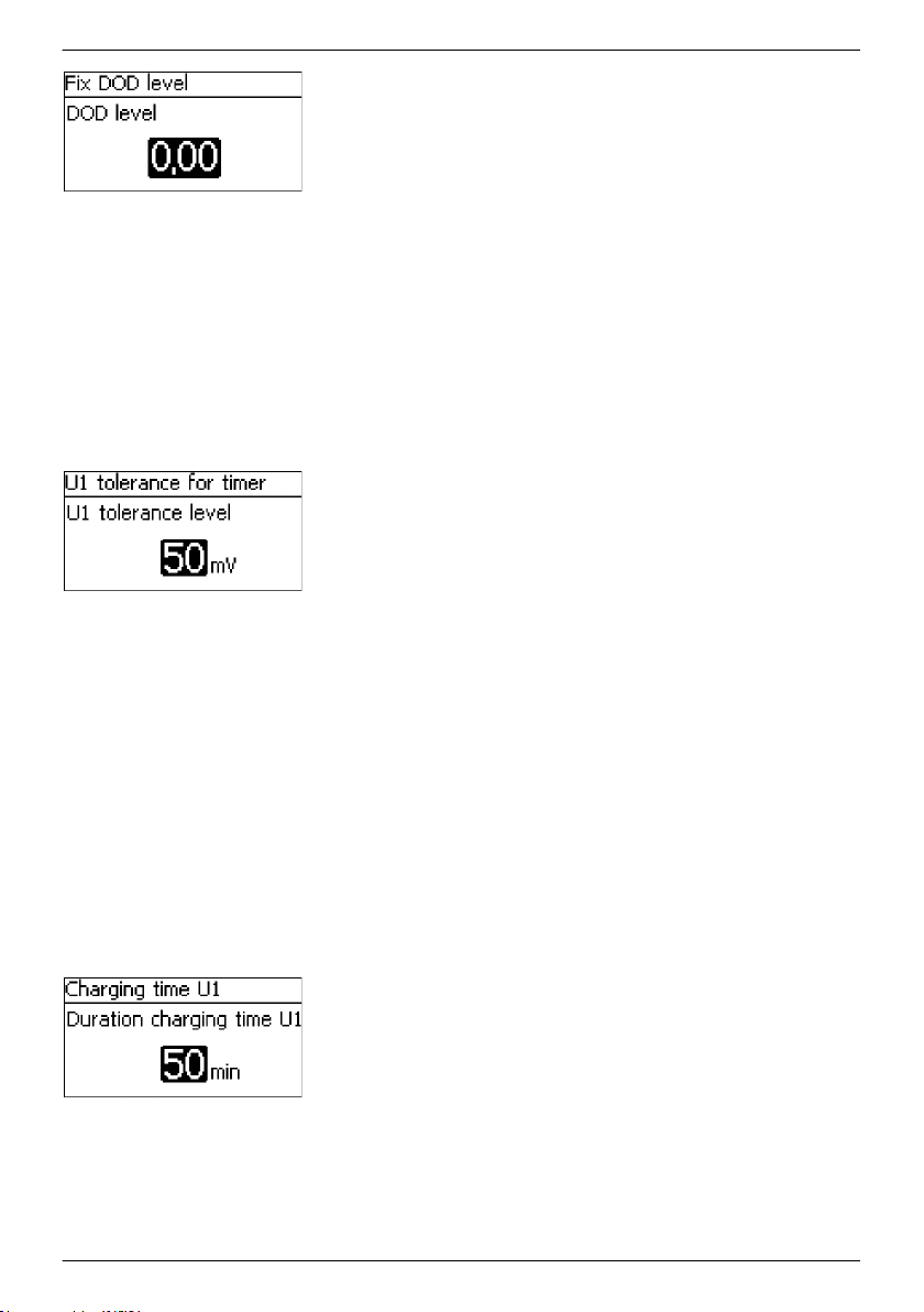
1. Press SET. The Fix DOD level dialogue appears (Fig. left).
2. Press SET. The value flashes.
3.
Press D, Ñ to change the value.
4. Press SET. The value stops blinking.
U1 tolerance for timer
NOTICES
n Die charging time U1 counts down when the actual
battery voltage lies within the range of the upper charge
voltage U1 minus the tolerance threshold.
n This allows toleration of short charging interruptions that
only result in a small reduction of the charge voltage.
✔
‘Main menu è Battery settings è NiCd battery settings
è U1 tolerance for timer
1. Press SET. The U1 tolerance for timer
(Fig. left).
2. Press SET. The value flashes.
3.
Press D, Ñ to change the value.
4. Press SET. The value stops blinking.
Charging time U1
NOTICES
n Period for which the upper charge voltage U1 minus the
tolerance threshold is to be maintained.
n Countdown of the charging time U1 is reset when the
device is restarted and at the start of a new day.
n This also occurs when the upper charge voltage U1 minus
the tolerance threshold is not reached over a period
greater than 5 h (continuously).
n Countdown of the charging time U1 is also reset when the
specified discharge depth for DOD reset charging is
reached.
✔
‘Main menu è Battery settings è NiCd battery settings
è Charging time U1’
1. Press SET. The Charging time U1 dialogue appears (Fig.
left).
2. Press SET. The value flashes.
3.
Press D, Ñ to change the value.
4. Press SET. The value stops blinking.
’
dialogue appears
82
756.404 | Z01 | 16.06
Page 83

DOD level charge reset
NOTICES
n Discharge depth at which countdown of the charging time
U1 is restarted.
n A value of 0.02 means a 2 % depth of discharge relative to
the configured battery capacity.
✔
‘Main menu è Battery settings è NiCd battery settings
è Charging time U1’
1. Press SET. The DOD level charge reset
(Fig. left).
2. Press SET. The value flashes.
3.
Press D, Ñ to change the value.
4. Press SET. The value stops blinking.
Lower charge voltage U2
NOTICE
Target value for the lower charge voltage U2 in the two-stage
charging process.
✔
‘Main menu è Battery settings è NiCd battery settings
è Lower charge voltage U2
1. Press SET. The Lower charge voltage U2 dialogue appears
(Fig. left).
2. Press SET. The value flashes.
3.
Press D, Ñ to change the value.
4. Press SET. The value stops blinking.
dialogue appears
’
Temp. factor U2 (>0°C)
NOTICES
n Temperature compensation factor for the lower end-of-
charge voltage U2 at positive temperatures.
n Specification of the adjustment factor in mV per cell and
per degree of temperature change.
✔
‘Main menu è Battery settings è NiCd battery settings
è Temp. factor U2 (>0°C)
1. Press SET. The Temp. factor U2 (>0°C)
(Fig. left).
2. Press SET. The value flashes.
3.
Press D, Ñ to change the value.
4. Press SET. The value stops blinking.
756.404 | Z01 | 16.06
’
dialogue appears
83
Page 84
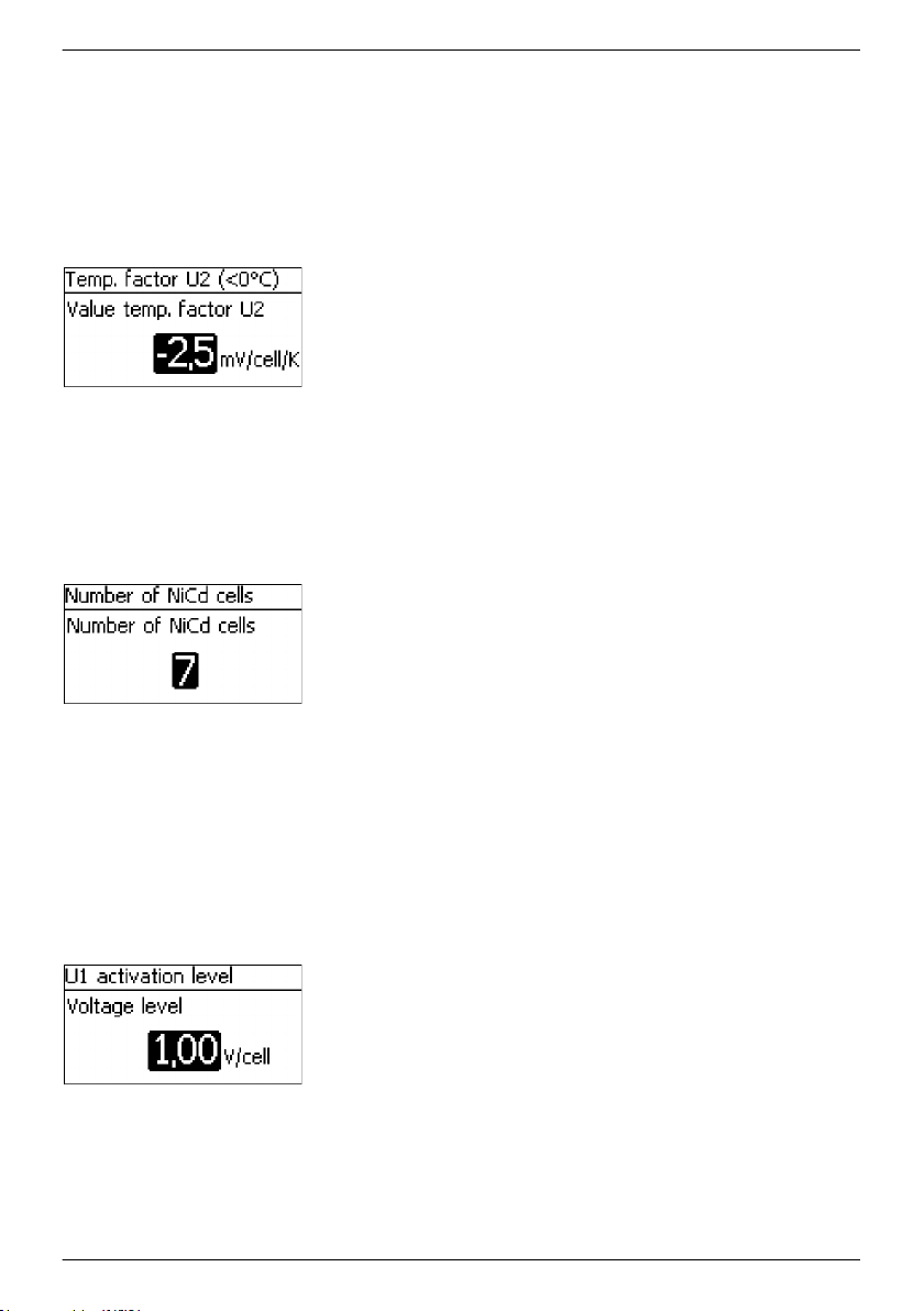
Temp. factor U2 (<0°C)
NOTICES
n Temperature compensation factor for the lower end-of-
charge voltage U2 at negative temperatures.
n Specification of the adjustment factor in mV per cell and
per degree of temperature change.
✔
‘Main menu è Battery settings è NiCd battery settings
è Temp. factor U2 (<0°C)
1. Press SET. The Temp. factor U1 (<0°C)
(Fig. left).
2. Press SET. The value flashes.
3.
Press D, Ñ to change the value.
4. Press SET. The value stops blinking.
Number of NiCd cells
NOTICE
The number of NiCd cells connected in series.
✔
‘Main menu è Battery settings è NiCd battery settings
è Number of NiCd cells’
1. Press SET. The Number of NiCd cells dialogue appears
(Fig. left).
2. Press SET. The value flashes.
3.
Press D, Ñ to change the value.
4. Press SET. The value stops blinking.
’
dialogue appears
U2 U1 switch
NOTICES
n Threshold for activation of the upper charge voltage U1 in
the two-stage charging process.
n The lower charge voltage U2 remains active if this
threshold is not crossed.
✔
‘Main menu è Battery settings è NiCd battery settings
è U2 U1 switch’
1. Press SET. The U1 activation level dialogue appears (Fig.
left).
2. Press SET. The value flashes.
3.
Press D, Ñ to change the value.
4. Press SET. The value stops blinking.
84
756.404 | Z01 | 16.06
Page 85
8.7.7 Battery temperature sensor
NOTICE!
– For the NiCd battery type, the temperature sensor is used for temperature compensation
of the upper charge voltage U1 and the lower charge voltage U2.
Ä
For the battery temperature sensor settings see
sensor’ on page 71.
Chapter 8.5.11 ‘Battery temperature
8.7.8 Cable compensation
For the cable compensation settings, see
system’ on page 33.
Ä
Chapter 5 ‘Initial commissioning of the base
8.7.9 PV string connection
For the PV string connection settings, see
on page 71.
Ä
Chapter 8.5.13 ‘PV string connection’
8.7.10 Expert menu
NOTICE!
– The expert menu for NiCd batteries allows the temperature compensation to be switched
on/off.
‘Expert menu settings è Temperature compensation
on page 72.
’ see Ä Chapter 8.5.14 ‘Expert menu’
8.8 StecaLink bus
NOTICE!
– The StecaLink bus is an RS-485 communication interface that uses a special Steca
transmission protocol.
Various different StecaLink-compatible devices can be networked together via the
–
StecaLink bus.
– Data exchange and/or remote function execution are possible via the StecaLink bus,
depending on the respective StecaLink member device.
– For information on connecting StecaLink member devices to the MPPT 6000-M/-S, see
Ä
Chapter 6.5 ‘StecaLink slave connection’ on page 45.
– Please visit
StecaLink devices and the software versions required.
756.404 | Z01 | 16.06
www.steca.com for continuously updated documentation on the compatible
85
Page 86
8.8.1 StecaLink slave address setting
StecaLink slave address
NOTICES
n Setting of the device address used for identifying the
device as a StecaLink slave node.
n Every device in a StecaLink communication network must
have a unique device address.
n Problems/error messages will occur during device
registration if multiple devices have the same address.
✔
‘Main menu è System settings è StecaLink slave addr.
1. Press SET. The RS485 address dialogue appears (Fig. left).
2. Press SET. The value flashes.
3.
Press D, Ñ to change the value.
4. Press SET. The value stops blinking.
8.8.2 StecaLink master setting (MPPT 6000-M only)
NOTICE!
– The master device in a StecaLink communication network controls the flow of data to the
StecaLink slave members.
The StecaLink slave members must be registered at the master device. Configuration of the
–
slaves must be performed at the master, depending on the type and functional scope of
each respective slave.
– See
Ä
Chapter 6.6 ‘StecaLink master connection (MPPT 6000-M only)’ on page 48 for
cabling information.
’
Add slave device
86
✔
‘Main menu è System settings è StecaLink master menu
è Add slave device
’
1. Press SET. The Set slave address dialogue appears (Fig.
left).
2. Press SET. The value flashes.
3.
Press D, Ñ to change the value.
4. Press SET. The value stops blinking. The StecaLink master
queries the entered address.
The detected StecaLink slave member is displayed (Fig. left).
5. Press SET. If additional settings for the registered slave are
possible then an additional menu is displayed.
For information on the further configuration parameters, see
‘Change slave settings’ (
Ä
‘Change slave settings’
on page 87).
756.404 | Z01 | 16.06
Page 87
‘No slave found’ – a StecaLink member device could not be
identified at the specified address. See Ä Chapter 10
‘Troubleshooting’ on page 111 for possible error correction
measures (see event message - Number 79).
‘Address already used’ - a StecaLink member device is already
registered under the specified address, see
‘Troubleshooting’ on page 111 for possible error correction
measures (see event message - Number 79).
Change slave settings
NOTICES
n Device-specific configuration of the slave registered at the
MPPT 6000-M is performed here.
n Different settings are available depending on the
functional scope of the slave.
✔
‘Main menu è System settings è StecaLink master menu
è Change slave settings
1. Press SET. The Change slave settings dialogue appears
with a list of the recognized StecaLink slave members. The list
is sorted by increasing order of the member addresses (Fig
left).
2.
Press D, Ñ to select the StecaLink slave member whose settings
are to be changed.
3. Press SET. The configuration menu for the selected slave
appears.
Further information on the individual configuration settings for
each respective slave is provided in the operating instructions
for the slave.
In the operating instructions for the PA HS400 current sensor.
In
Ä
Chapter 8.8.3 ‘Changing the MPPT 6000-S slave settings
(MPPT 6000-M only)’ on page 87 of these operating
instructions for the MPPT 6000-S.
Ä
Chapter 10
’
8.8.3 Changing the MPPT 6000-S slave settings (MPPT 6000-M only)
Topics
1.
Ä
‘Selecting the MPPT slave’ on page 88
2.
Ä
‘Changing Tarom MPPT 6000-S slave settings’ on page 88
3.
Ä
‘Configuring the operating mode’ on page 89
4.
Ä
‘Delete slave’ on page 90
5.
Ä
‘Synchronising slave’ on page 91
756.404 | Z01 | 16.06
87
Page 88

Selecting the MPPT slave
✔
‘Main menu è System settings è StecaLink master menu
è Change slave settings’
1. Press SET. The Change slave settings dialogue appears
with a list of the recognised StecaLink slave members. The list
is sorted by increasing order of the member addresses (Fig
left).
2.
Press D, Ñ to select the MPPT 6000-S whose settings are to be
changed.
3. Press SET. The Settings MPPT slave dialogue appears,
with the configuration menu for the MPPT 6000 (Fig. left).
Changing Tarom MPPT 6000-S slave settings
Name
NOTICES
n An individual name can be assigned to each StecaLink
MPPT 6000-S.
n Assignment of a name is optional and is not required for
operating the device.
n The name is shown in the measurements display on the
status screen.
n The following applies to the MPPT 6000-S:
–
n The following printable ASCII characters can be used for
entering an individual name: !"#$%&'()*+,-./
0123456789:;<=>?
@ABCDEFGHIJKLMNOPQRSTUVWXYZ[\]^_`abcdefghijklm
nopqrstuvwxyz{|}~
n An individual name with a length of up to 8 characters
can be entered.
✔
‘Main menu è System settings è StecaLink master menu
è Change slave settings è Selection [ xx - MPPT 6000]
è Name’
1. Press SET. The Set slave display name
(Fig. left).
2.
Press D, Ñ to select the character position.
3. Press SET. The entry position blinks.
4.
Press D, Ñ to select the desired character.
5. Press SET. The entry position stops blinking.
The selected character is adopted.
6.
Repeat steps 2.-5. until the desired name with max. 8
characters has been entered.
7. Press Ñ to exit the data entry dialogue.
The MPPT 6000 device name is assigned as fixed
value.
dialogue appears
88
756.404 | Z01 | 16.06
Page 89

Configuring the operating mode
NOTICE!
– The Tarom MPPT 6000-S StecaLink slave member can be integrated into a master/slave
system with various different function scopes.
– Save setting: This specifies that the following settings in the master are to be
transferred to the slave and locally stored in the slave:
date format,
date,
time format,
time,
language,
acoustic alarm,
backlighting,
battery type (only for the lead-acid battery type, not for Li-Ion, NiCd),
battery capacity,
float charge voltage,
boost charge activation threshold,
boost charge voltage,
boost charge duration,
equalisation charge on/off and cycle,
equalisation charge activation threshold,
equalisation charge voltage,
equalisation charge duration.
The Save setting setting configuration allows the MPPT 6000-S to continue
–
operating locally using the previously transferred settings if communication with the
master is interrupted. This function is only available for the lead-acid and lead-gel/
AGM battery types supported by the MPPT 6000-S. Settings for other battery types
that can be selected at the master cannot be stored in the MPPT 6000 slave.
– Selecting Save setting does not trigger a data transfer to the slave. The
Synchronise function must be executed in order to transfer the settings from the
master to the slave, see
Ä
‘Synchronising slave’ on page 91.
– Single mode: This specifies that the slave is to be used as a single device,
independently of the master. This allows individual configuration of the slave,
independently of the master. In this case the master does not send control parameters
to the slave. Information is still exchanged. The master reads information from the
slave for display and data logging purposes.
– Master mode: This specifies that the charge functions of the slave are controlled by
the master. The master transmits the current control parameter settings to the slave.
The slave adopts these control parameter settings and can thus be centrally controlled
by the master. The master also reads information from the slave for display and data
logging purposes.
The master mode of the MPPT 6000-S is possible for the lead-acid, lead-gel/AGM and
NiCd battery types. The master transmits the necessary charge voltage and current
control parameters for all battery types. If communication with the master is
interrupted then all registered MPPT 6000-S devices are switched off for safety
reasons; disconnected MPPT 6000-S devices perform a reset and then start anew in
the ‘OFF’ state. If the ‘Device On/Off è Redundancy’ function is active at the MPPT
6000-S and a lead-acid battery system was previously charged in conjunction with the
MPPT 6000-M then the MPPT 6000-S device(s) begin operating independently if the
756.404 | Z01 | 16.06
89
Page 90

control communication with the master is interrupted, see Ä Chapter 6.8
‘Redundancy function (MPPT 6000-S only)’ on page 51. If the MPPT 6000-M was
previously operated with a Li-Ion or NiCd system, then the automatic redundancy
function of the MPPT 6000-S is not activated for safety reasons. In this state the
battery selection at the MPPT 6000-S is undefined. The user can manually set the
charge parameters for lead-acid batteries.
– A combination of the Save setting and Single mode or Master mode configurations
is possible.
– A combination of Single mode and Master mode is not prevented but is not sensible.
In this combination the Master mode takes precedence.
Configuration MPPT slave
✔
‘Main menu è System settings è StecaLink master menu
è Change slave settings è Selection [ xx - Tarom MPPT 6000]
è Configuration MPPT Slave
’
1. Press SET. The Configuration MPPT slave dialogue
appears (Fig. left).
2.
Press D, Ñ. The selected configuration is marked.
3. Press SET. The Settings MPPT slave dialogue appears,
with the configuration menu for the Tarom MPPT 6000-S (Fig.
left).
4. Repeat steps 2. and 3. if necessary until the desired
configurations have been selected.
5. Press ESC to exit the menu.
Delete slave
NOTICE!
– StecaLink slave members can be deleted to remove them from the communications
network.
This is necessary when StecaLink slave members have been removed or their slave address
–
has been changed.
– Display and data logging data is no longer exchanged with a StecaLink slave member after
it has been deleted.
– Deleted slave members are removed from all other relevant configuration lists in the MPPT
6000-M.
Delete slave
✔
‘Main menu è System settings è StecaLink master menu
è Delete slave
’
1. Press SET. The Delete slave dialogue appears with a list of
the recognised StecaLink slave members. The list is sorted by
increasing order of the member addresses. (Fig. left).
2.
Press D, Ñ to select the StecaLink slave member to be deleted.
90
756.404 | Z01 | 16.06
Page 91
3. Press SET. The Delete slave dialogue appears (Fig. left).
4. Hold SET pressed for 1 s. The selected slave is deleted.
Synchronising slave
NOTICE!
– The Synchronise slave function actively transfers the parameter settings of the MPPT 6000-
M master to all MPPT 6000-S slaves.
StecaLink PA HS400 slaves are not synchronised. No configurable data is stored in the PA
–
HS400.
– Each MPPT slave executes a reset after receiving the information, in order to adopt the
new values.
– The reset interrupts charging, switches off the module and battery relays and executes a
complete restart of the device.
– Charging is started again after a restart caused by synchronising, depending on the
configuration of the slaves, see
Ä
‘Configuring the operating mode’ on page 89 and the
Device On/Off state of the master.
– The restart causes each MPPT 6000-S to perform a new system voltage detection, see
Ä
Chapter 4.4 ‘Supplying the controller with voltage’ on page 31.
– If ‘Save setting’ is set for the slave in the Configuration MPPT slave menu ,
see
Ä
‘Configuring the operating mode’ on page 89, then the settings are saved in the
MPPT 6000-S.
Synchronising
✔
‘Main menu è System settings è StecaLink master menu
è Synchronise
’
1. Press SET. The Synchronise slave dialogue appears (Fig.
left).
2. Hold SET pressed for 1 s. The transmission is started.
3. The display automatically changes to the higher-level menu.
8.9 Internal data logger
The data logger stores the following data in the internal memory:
n Energy input
n Energy output (MPPT 6000-M only)
n Min. battery voltage
n Max. battery voltage
n Max. charging current
n Max. PV 1 voltage
n Max. PV 2 voltage
756.404 | Z01 | 16.06
91
Page 92

Data stored in the internal memory can be
n shown on the display and
n deleted from the memory.
8.9.1
The following points can be selected in the Energy input menu:
n Last 18 hours,
n Day,
n Month,
n Year,
n Total,
n Configuration,
Energy input
Last 18 hours
NOTICES
Energy input
Ä
‘Energy input’ on page 92
Ä
‘Energy input’ on page 92
Ä
‘Energy input’ on page 93
Ä
‘Energy input’ on page 93
Ä
‘Energy input’ on page 94
Ä
‘Energy input’ on page 94
n Memory of the information on the amount of input
energy in Ah.
n Graphical overview representing the last 18 hours.
✔
‘Main menu è Internal data logger è Energy input
è Last 18 hours
1. Press SET. The graphical representation is displayed (Fig. left).
2. Press ESC. Navigate back to selection.
’
Energy input
Day
NOTICES
n Amount of input energy in Ah over the last 30 days.
n A graphical overview is not possible.
92
✔
‘Main menu è Internal data logger è Energy input è Day’
1. Press SET. List of data is displayed (Fig. left).
2.
Press D, Ñ to page through the list of data.
3. Press ESC. Navigate back to selection.
756.404 | Z01 | 16.06
Page 93

Energy input
Month
NOTICES
n Amount of input energy in Ah for the current month and
the last 11 months.
n A graphical representation is possible.
✔
‘Main menu è Internal data logger è Energy input è Month’
1. Press SET. List of data is displayed (Fig. left).
2.
Press D, Ñ to page through the list of data.
3. Press SET. A graphical representation of the month appears.
4. Press ESC. Navigate back to the list of data.
Energy input
Year
NOTICES
n Amount of input energy in Ah for the current year and the
last 19 years.
n Earliest starting year is 2000.
n A graphical representation is possible.
✔
‘Main menu è Internal data logger è Energy input è Year’
1. Press SET. List of data is displayed (Fig. left).
2.
Press D, Ñ to page through the list of data.
3. Press SET. A graphical representation of the year appears.
4. Press ESC. Navigate back to the list of data.
756.404 | Z01 | 16.06
93
Page 94

Energy input
Total
NOTICES
n Total amount of energy loaded into the device since initial
commissioning.
n A graphical overview is not possible.
✔
‘Main menu è Internal data logger è Energy input è Total’
1. Press SET. An information window appears (Fig. left).
2. Press ESC. Navigate back to selection.
Energy input
Settings
NOTICES
n This dialogue is used for selecting the devices whose
current/power information is to be included in the energy
input data logging.
n Only the information sources selected in this list are used
for determining the energy input values.
✔
‘Main menu è Internal data logger è Energy input
è Configuration
1. Press SET, the Energy input members dialogue appears
(Fig. left).
2.
Press D, Ñ to change the selection.
3. Press SET. The check box is activated or deactivated
accordingly and the selection is adopted.
4. Press ESC. Navigate back to the Configuration menu.
’
8.9.2 Energy output (MPPT 6000-M only)
n Record of the information on the amount of output energy in Ah. Optional StecaLink members
such as PA HS400 current sensors are required in addition to the MPPT 6000-M in order to
register discharging of the battery.
n Discharge energy values cannot be recorded if no additional devices for measuring discharge
currents are present.
n The following points can be selected in the Energy output menu:
–
Last 18 hours,
– Day,
– Month,
– Year,
– Total,
– Configuration,
94
Ä
Ä
Ä
Ä
‘Energy output’ on page 95
‘Energy output’ on page 95
Ä
‘Energy output’ on page 95
‘Energy output’ on page 96
‘Energy output’ on page 96
Ä
‘Energy output’ on page 97
756.404 | Z01 | 16.06
Page 95

Energy output
Last 18 hours
NOTICES
n Memory of the information on the amount of output
energy in Ah.
n Graphical overview representing the last 18 hours.
✔
‘Main menu è Internal data logger è Energy output
è Last 18 hours
1. Press SET. The graphical representation is displayed (Fig. left).
2. Press ESC. Navigate back to selection.
Energy output
Day
NOTICES
n Amount of discharged energy in Ah over the last 30 days.
n A graphical overview is not possible.
✔
‘Main menu è Internal data logger è Energy output è Day’
1. Press SET. List of data is displayed (Fig. left).
2.
Press D, Ñ to page through the list of data.
3. Press ESC. Navigate back to selection.
’
Energy output
Month
NOTICES
n Amount of discharged energy in Ah for the current month
and the last 11 months.
n A graphical representation is possible.
✔
‘Main menu è Internal data logger è Energy output
è Month’
1. Press SET. List of data is displayed (Fig. left).
2.
Press D, Ñ to page through the list of data.
756.404 | Z01 | 16.06
95
Page 96
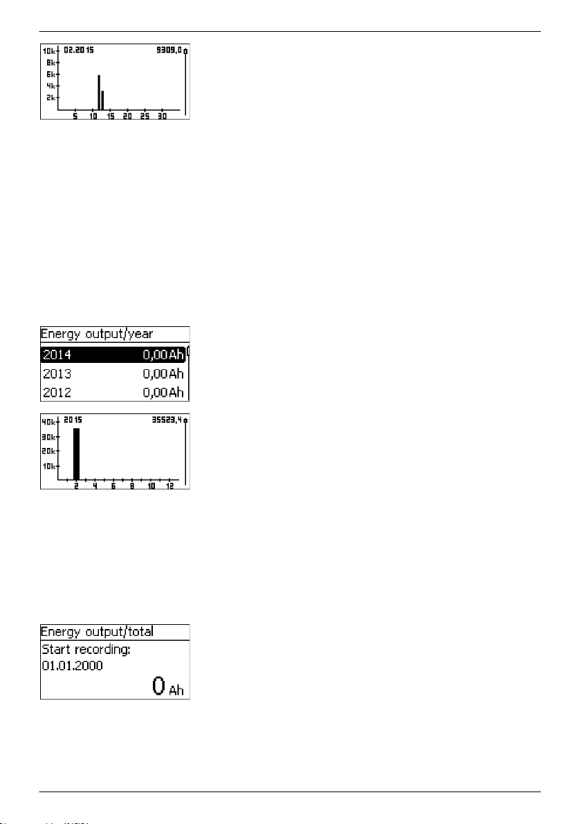
3. Press SET. A graphical representation of the month appears.
4. Press ESC. Navigate back to the list of data.
Energy output
Year
NOTICES
n Amount of discharged energy in Ah for the current year
and the last 19 years.
n Earliest starting year is 2000.
n A graphical representation is possible.
✔
‘Main menu è Internal data logger è Energy output è Year’
1. Press SET. List of data is displayed (Fig. left).
2.
Press D, Ñ to page through the list of data.
3. Press SET. A graphical representation of the year appears.
4. Press ESC. Navigate back to the list of data.
Energy output
Total
NOTICES
n Total amount of energy output from the device since
initial commissioning.
n A graphical overview is not possible.
✔
‘Main menu è Internal data logger è Energy output è Total’
1. Press SET. An information window appears (Fig. left).
2. Press ESC. Navigate back to selection.
96
756.404 | Z01 | 16.06
Page 97
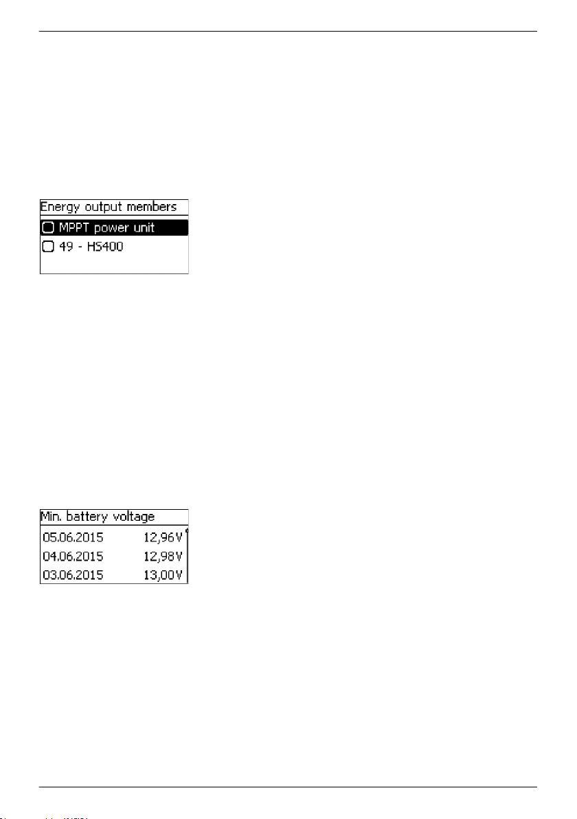
Energy output
Configuration
NOTICES
n This dialogue is used for selecting the devices whose
current/power information is to be included in the energy
output logging.
n Only the information sources selected in this list are used
for determining the energy output values.
✔
‘Main menu è Internal data logger è Energy output
è Configuration
’
1. Press SET, the Energy output members dialogue appears
(Fig. left).
2.
Press D, Ñ to change the selection.
3. Press SET. The check box is activated or deactivated
accordingly and the selection is adopted.
4. Press ESC. Navigate back to the Configuration menu.
8.9.3 Min./Max. values
The following min./max. values can be queried in the Internal data logger menu:
Ä
‘Minimum battery voltage’ on page 97
n
n
Ä
‘Maximum battery voltage’ on page 97
n
Ä
‘Maximum charge current’ on page 98
n
Ä
‘Maximum PV 1 voltage’ on page 98
n
Ä
‘Maximum PV 2 voltage’ on page 98
Minimum battery voltage
NOTICES
n Record of the minimum battery voltage for each day over
the last 30 days.
n A value of 0.00 V is displayed if the device was not active.
✔
‘Main menu è Internal data logger è Min. battery voltage
1. Press SET. List of data is displayed (Fig. left).
2.
Press D, Ñ to page through the list of data.
3. Press ESC. Navigate back to the menu.
’
Maximum battery voltage
NOTICES
n Record of the maximum battery voltage for each day over
the last 30 days.
n A value of 0.00 V is displayed if the device was not active.
756.404 | Z01 | 16.06
✔
‘Main menu è Internal data logger è Max. battery voltage
’
97
Page 98
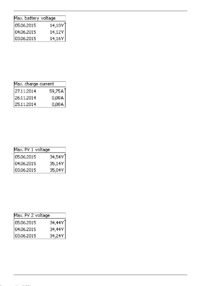
1. Press SET. List of data is displayed (Fig. left).
2.
Press D, Ñ to page through the list of data.
3. Press ESC. Navigate back to the menu.
Maximum charge current
NOTICES
n Record of the maximum battery charge current for each
day over the last 30 days.
n A value of 0.00 A is displayed if the device was not active.
✔
‘Main menu è Internal data logger è Max. charge current
1. Press SET. List of data is displayed (Fig. left).
2.
Press D, Ñ to page through the list of data.
3. Press ESC. Navigate back to the menu.
Maximum PV 1 voltage
NOTICES
n Record of the maximum voltage measured at connection
M1 for each day over the last 30 days.
n A value of 0.00 V is displayed if the device was not active.
✔
‘Main menu è Internal data logger è Max. PV 1 voltage
1. Press SET. List of data is displayed (Fig. left).
2.
Press D, Ñ to page through the list of data.
3. Press ESC. Navigate back to the menu.
’
’
Maximum PV 2 voltage
NOTICES
n Record of the maximum voltage measured at connection
M2 for each day over the last 30 days.
n A value of 0.00 V is displayed if the device was not active.
✔
‘Main menu è Internal data logger è Max. PV 2 voltage
1. Press SET. List of data is displayed (Fig. left).
2.
Press D, Ñ to page through the list of data.
3. Press ESC. Navigate back to the menu.
98
’
756.404 | Z01 | 16.06
Page 99
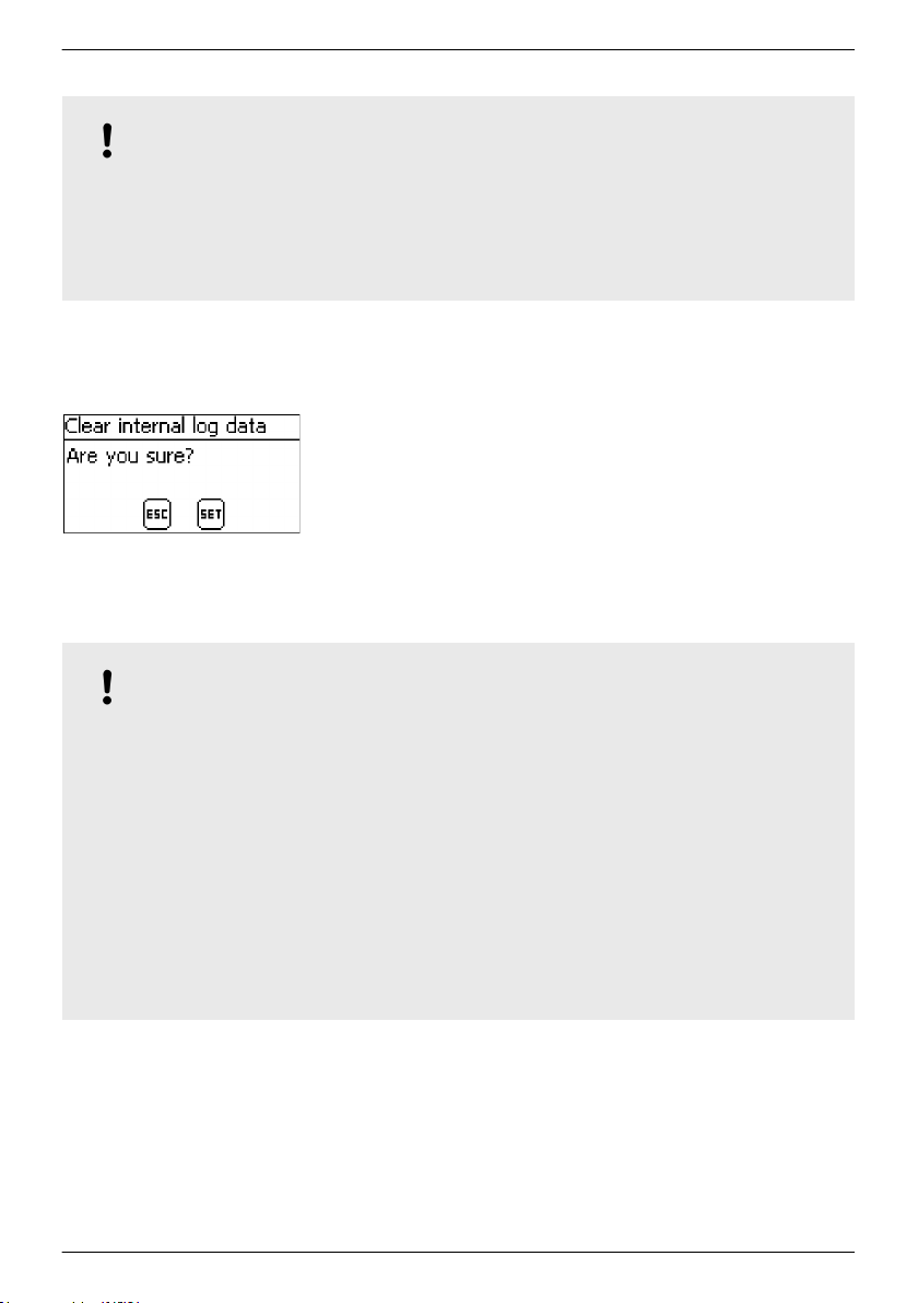
8.10 Clear log data
NOTICE!
– The entries in the internal data logger are deleted via the ‘Clear log data’ menu item.
The ‘Energy input total’ and ‘Energy output total’ information is not deleted.
–
– The Hours-of-operation value displayed in the measurements section of the status screen is
not deleted.
– The logged data on the SD card is not deleted.
Clear log data
✔
✔‘Main menu è System settings è Clear log data’
1. Press SET. The Clear internal log data dialogue appears
(Fig. left).
2. Press SET for 1 s. All internal log data, except for the total yield
data, is deleted.
8.11 Clear event log
Ä
Chapter 10.2 ‘Event messages’ on page 111.
See
8.12 Factory settings
NOTICE!
– All active device functions are stopped when a factory reset is performed.
The values configured by a factory reset are specified in
–
on page 124.
– Executing a factory reset deletes all settings and resets the values to the factory default
values. The device then performs a reset.
– Executing a factory reset also deletes data in the internal data logger. The operating hours
counter and the Energy input total/Energy output total values are retained.
– All application-specific settings must then be configured anew.
– Parameter settings that are not saved on an SD card are lost when a factory reset is
executed.
– Save the configured parameters on the SD card before executing a factory reset (MPPT
6000-M only).
– The settings can then be reloaded from the SD card after the device has restarted.
Ä
Chapter 12 ‘Technical data’
756.404 | Z01 | 16.06
99
Page 100

Factory reset
✔
‘Main menu è System settings è Factory reset’
1. Press SET. The Factory setting dialogue appears (Fig. left).
2. Press SET for 1 s. A factory reset is executed and all settings
are reset to the factory default values.
8.13 UART/RS-232 interface (MPPT 6000-M only)
NOTICE!
Ä
– For the RS-232 interface connection, see
(MPPT 6000-M only)’ on page 50.
– For the scope of the data transmission, see
protocol (MPPT 6000-M only)’ on page 142.
RS-232 port
✔
‘Main menu è System settings è RS-232 port
1. Press SET. The RS-232 port
2.
Press D, Ñ to change the selection.
3. Press SET. The selection is adopted.
Chapter 6.7 ‘UART/RS-232 interface connection
Ä
Chapter 12.3 ‘UART/RS-232 interface
dialogue appears (Fig. left).
’
8.14 Acoustic alarm
NOTICE!
– The device has an audible alarm unit that emits a beeping alarm signal when an error or
warning occurs.
The alarm signal remains active while the error or warning is active or until the user
–
confirms the error or warning via SET.
Acoustic alarm
100
✔
‘Main menu è System settings è Acoustic alarm’
1. Press SET. The Acoustic alarm dialogue appears (Fig. left).
2.
Press D, Ñ to change the selection.
3. Press SET. The selection is adopted.
756.404 | Z01 | 16.06
 Loading...