

Page 1
Solarix MPPT 3020 / MPPT 5020
Installations- und Bedienungsanleitung
DE
764392 | Z01 | 18.43
Page 2

DE
Vorwort
Vielen Dank, dass Sie sich für einen Solarladeregler aus unserem Hause entschieden haben. Sie leisten durch die Nutzung der Sonnenenergie einen wesentlichen Beitrag zum
Umweltschutz, indem Sie die Belastung der Erdatmosphäre durch Kohlendioxyd (CO2) und
anderen schädlichen Gasen insgesamt verringern.
Alle Rechte, auch die der Übersetzung, vorbehalten. Kein Teil dieses Handbuchs darf in
irgendeiner Form ohne unsere schriftliche Zustimmung reproduziert oder unter Verwendung elektronischer Systeme verarbeitet werden.
2
Page 3

Inhaltsverzeichnis
1 Allgemeine Hinweise .................................................................. 4
2 Sicherheitshinweise .................................................................... 5
2.1 Kennzeichnungen und Symbole ........................................................................... 6
2.1.1 Sicherheitskennzeichen ........................................................................................ 6
2.1.2 Signalwörter .......................................................................................................... 6
3 Bestimmungsgemäße Verwendung .......................................... 7
4 Übersicht ...................................................................................... 8
5 Installation ................................................................................... 9
6 Bedienung .................................................................................. 13
6.1 Einschalten/Ausschalten ..................................................................................... 15
6.2 Umschalten der Anzeige: .................................................................................... 16
6.3 Einstellungsmenü ............................................................................................... 18
7 Wartung und Pflege .................................................................. 26
8 Entsorgung ................................................................................ 27
9 Störungsbehebung ................................................................... 27
9.1 Was tun bei Störungen ....................................................................................... 28
10 Technische Daten ..................................................................... 30
11 Gewährleistung und Garantiebestimmungen ......................... 32
3
Page 4

DE
1 Allgemeine Hinweise
Der Solarladeregler ist in zwei Leistungsstufen (30 A und 50 A) erhältlich.
Das Gerät erfüllt folgende Aufgaben:
• Leistungsausbeute der angeschlossenen Solarmodule optimieren
• Ladevorgang der Batterie regeln
• Ladezustand der Batterie überwachen
• Zu- und Abschaltung der am Lastausgang angeschlossenen Verbraucher steuern
Merkmale
• Intelligentes Maximum Power Point Tracking
• Automatische Batteriespannungserfassung
• Dreistufiger Ladevorgang zur Optimierung der Batterieleistung
• Maximaler Wirkungsgrad bis zu 99 %
• Anwendungsabhängig konfigurierbarer Ladestrom
• Unterstützung unterschiedlicher Batterietypen
• Hintergrundbeleuchtung
• Datenausgabe über serielle Schnittstelle (RS-232)
Das Gerät ist auf dem neuesten Stand der Technik mit einem optimierten "Maximum
Power Point Tracking (MPPT)"-Algorithmus ausgestattet und damit in der Lage, zu jedem
Zeitpunkt und bei unterschiedlichen Umgebungsbedingungen die maximal verfügbare Leistung des Solarmoduls zu nutzen.
Das Typenschild mit den erforderlichen Angaben zum Gerät und zum Hersteller ist an der
Seite unten rechts angebracht.
Die Konformitätserklärung ist auf der Internetseite des Herstellers einsehbar.
Lieferumfang
• 1 Stück Solarladeregler
• 1 Stück Installations- und Bedienungsanleitung
Vor der Installation prüfen, ob die Verpackung und das Gerät unbeschädigt sind.
4
Page 5

DE
2 Sicherheitshinweise
Dieses Dokument ist Teil des Produkts.
• Betriebsanleitung vor Installation und Gebrauch aufmerksam und vollständig lesen.
• Betriebsanleitung während der Lebensdauer in der Nähe des Geräts aufbewahren.
• Betriebsanleitung an jeden folgenden Besitzer oder Benutzer des Produkts weiterge-
ben.
Die Installation darf nur durch eine qualifizierte Elektro-Fachkraft erfolgen.
Das Solarmodul und die Batterie liefern elektrische Spannung an das Gerät, auch wenn
dieses ausgeschaltet ist. Bei Anschließen und Trennen von Solarmodul oder Batterie genau nach den Anweisungen in Kapitel 5 vorgehen.
Falsch angeschlossene Komponenten können das Gerät beschädigen.
Durch unsachgemäße Bedienung kann der Ertrag der Solaranlage gemindert werden.
Außerdem können Anlagenteile beschädigt werden.
Gerät sofort außer Betrieb setzen und von Batterie und Solarmodul trennen, wenn eine der
folgenden Komponenten beschädigt ist:
• Gerät (keine Funktion, sichtbare Beschädigung, Rauchentwicklung, eingedrungene
Flüssigkeit etc.)
• Anschlussklemmen und angeschlossene Leitungen
• Solarmodul
Gerät nicht wieder einschalten, bevor es vom Händler oder Hersteller repariert wurde bzw.
bevor beschädigte Leitungen oder Solarmodule von einer Fachkraft repariert wurden.
Gerät nicht abdecken.
Zur Vermeidung von Brand- und Explosionsgefahr folgende Hinweise beachten:
• Den Solarladeregler nicht verwenden in staubhaltiger Umgebung, in der Nähe von Lösungsmitteln oder wenn brennbare Gase und Dämpfe auftreten können.
• Kein offenes Feuer oder Licht in der Nähe der Batterien verwenden. Funkenbildung vermeiden.
• Für ausreichende Belüftung des Raums sorgen.
• Ladevorgang regelmäßig kontrollieren.
• Ladehinweise des Batterieherstellers beachten.
Gehäuse nicht öffnen: Es besteht Lebensgefahr! Beim Öffnen des Gehäuses verfällt außerdem der Garantieanspruch. Gerät nur durch eine qualifizierte Fachwerkstatt oder den
Hersteller instand setzen lassen.
Vom Hersteller angebrachte Schilder und Kennzeichnungen nicht verändern, entfernen
oder unkenntlich machen.
Beim Anschließen eines externen Geräts, das nicht in diesem Dokument beschrieben ist,
die Anleitung des Herstellers beachten. Falsch angeschlossene Geräte können den Solarladeregler beschädigen.
5
Page 6
DE
Warnzeichen
Art der Gefahr
Signalwort
Bedeutung
Dieses Gerät nicht von folgenden Personen bedienen lassen:
• Kinder
• Personen mit physischen, sensorischen oder mentalen Beeinträchtigungen
• Personen, die nicht über ausreichende Erfahrungen und Kenntnisse verfügen (es sei
denn, sie wurden durch eine Person, die für ihre Sicherheit verantwortlich ist, in der Benutzung des Geräts unterwiesen und anfänglich beaufsichtigt)
Sicherheitshinweise der angeschlossenen Batterie beachten. Die Ladespannungen und
Ströme müssen gemäß der Batterie-Dokumentation am Solarladeregler eingestellt werden.
Der Hersteller übernimmt keine Verantwortung für Beschädigungen durch falsch eingestellte Solarladeregler-Parameter.
Sicherheitshinweise des angeschlossenen Solarmoduls beachten.
Die allgemeinen und nationalen Sicherheits- und Unfallverhütungsvorschriften beachten.
2.1 Kennzeichnungen und Symbole
2.1.1 Sicherheitskennzeichen
Auf dem Gerät und in dieser Anleitung werden die folgenden Sicherheitskennzeichen verwendet:
Warnung vor gefährlicher elektrischer Spannung
Warnung vor einer Gefahrenstelle
Anleitung beachten
2.1.2 Signalwörter
In dieser Anleitung werden folgende Signalwörter verwendet:
GEFAHR
WARNUNG
HINWEIS
6
Weist auf eine gefährliche Situation hin, die zum Tod oder zu schweren
Verletzungen führt, wenn sie nicht gemieden wird.
Weist auf eine möglicherweise gefährliche Situation hin, die zum Tod
oder zu schweren Verletzungen führen kann, wenn sie nicht gemieden
wird.
Weist auf eine möglicherweise gefährliche Situation hin, die zu Sachund Umweltschäden führen kann, wenn sie nicht gemieden wird.
Page 7
DE
3 Bestimmungsgemäße Verwendung
Der Solarladeregler ist für photovoltaische (PV) Anlagen zum Laden von Batterien mit einer Nennspannung von 12 VDC oder 24 VDC (50-A-Ausführung auch 48 VDC) geeignet.
Die Einsatzbereiche umfassen den Bereich Hobby und Freizeit, Wohn-, Geschäfts-, Gewerbebereich sowie Kleinbetriebe.
Installation, Inbetriebnahme und Demontage des Geräts dürfen nur durch ausgebildetes
Fachpersonal unter Beachtung der vor Ort geltenden Installationsvorschriften erfolgen.
Das Fachpersonal muss mit dieser Bedienungsanleitung vertraut sein und die Anweisungen befolgen.
Der Endkunde darf nur die Bedienfunktionen ausführen.
Der Solarladeregler arbeitet mit Gleichstrom und darf nicht an das öffentliche Wechselstromnetz angeschlossen werden.
Der Betrieb ist nur in Innenräumen zulässig.
Der Solarladeregler ist nur für die Regelung von Solarmodulen geeignet. Keine anderen
Ladequellen an den Solarladeregler anschließen. Ansonsten können der Solarladeregler
und/oder die Quelle zerstört werden.
Die angeschlossenen Solarmodule und Batterien müssen den angegebenen Spezifikationen entsprechen (siehe Kapitel 10).
Der Solarladeregler ist grundsätzlich für folgende aufladbare Batterietypen geeignet:
• Blei-Akkumulatoren mit flüssigen Elektrolyten
• Verschlossene Blei-Akkumulatoren; AGM, GEL
• Lithium-Ionen-Batterien
HINWEIS
Der Bediener muss sicherstellen, dass die Einstellungen des Solarladereglers mit den Angaben im Batterie-Datenblatt übereinstimmen.
Es dürfen nur Lithium-Ionen-Batterien mit integriertem BMS (Batterie-Management-System) und einer Sicherheits-Schutzabschaltung der Batterie im
Fehlerfall eingesetzt werden unter der Voraussetzung, dass keine Kommunikation mit dem BMS erforderlich ist.
Der jeweilige Batterietyp muss am Solarladeregler eingestellt werden, siehe Kapitel 6. Die
Voreinstellung ist Bleibatterie GEL/AGM.
Weitere Batterietypen können konfiguriert werden. Fehlerhafte Konfiguration kann den
Solarladeregler oder die Batterie beschädigen. Die Verwendung dieser Programmfunktion
erfolgt auf Verantwortung des Bedieners.
7
Page 8
DE
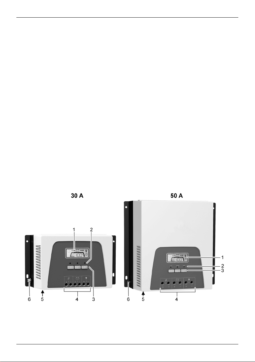
1 Display (LCD)
4 Elektrische Anschlüsse
Haftungsausschluss
Sowohl das Einhalten dieser Anleitung als auch die Bedingungen und Methoden bei Installation, Betrieb, Verwendung und Wartung des Solarladereglers können vom Hersteller
nicht überwacht werden. Eine unsachgemäße Ausführung der Installation kann zu Sachschäden führen und in Folge Personen gefährden.
Daher übernehmen wir keinerlei Verantwortung und Haftung für Verluste, Schäden oder
Kosten, die sich aus fehlerhafter Installation, unsachgemäßem Betrieb sowie falscher Verwendung und Wartung ergeben oder in irgendeiner Weise damit zusammenhängen.
Ebenso übernehmen wir keine Verantwortung für patentrechtliche Verletzungen oder Verletzung anderer Rechte Dritter, die aus der Verwendung dieses Solarladereglers resultieren.
Der Hersteller behält sich das Recht vor, ohne vorherige Mitteilung Änderungen bezüglich
Produkt, technischen Daten oder Montage- und Betriebsanleitung vorzunehmen.
Achtung: Öffnen des Geräts, Manipulations- und Reparaturversuche sowie nicht bestimmungsgemäßer Betrieb führen zu Gewährleistungs- bzw. Garantieverlust.
4 Übersicht
Zwei Ausführungen für unterschiedliche Ladeströme sind erhältlich:
• Solarladeregler 30 A
• Solarladeregler 50 A
2 LEDs
3 Tasten
5 Kommunikationsschnittstelle (für Zubehör)
6 Erdungsanschluss
8
Page 9
Der Solarladeregler optimiert die Batterieladung und die Batterielebensdauer durch einen
dreistufigen Ladealgorithmus und eine konfigurierbare Ausgleichsladung:
Ladestufe Beschreibung
DE
Hauptladung
(Bulk charge state)
Wartungsladung
(Absorption stage)
Schwebeladung
(Float stage)
Die Batterie wird mit der maximal möglichen Leistung
geladen, abhängig vom Input der Solarmodule
Batterieladung mit konstanter Spannung. Die Dauer der
Wartungsladung ist einstellbar.
Erhaltungsladung mit konstanter Spannung. Wenn die
Batteriespannung unter die Schwellenspannung für die
Schwebeladung fällt, wird auf Hauptladung umgeschaltet.
Ausgleichsladung
(Equalize stage)
Die Ausgleichsladung regeneriert die Batterie, um den
Kapazitätsverlust über die Lebensdauer möglichst gering zu
halten.
Die Funktion Ausgleichsladung wird durch die Einstellungen in den Programmen 07, 08, 09, 10, 11, 12 und 13
gesteuert. Um die Funktion zu nutzen, muss sie im Programm 07 aktiviert werden.
Zubehör (nicht enthalten):
PA WiFi1: W-LAN-Box, um den Solarladeregler mit einem Internetportal zu verbinden.
5 Installation
GEFAHR
Elektrische Spannung
Bei Sonneneinstrahlung können die Solarmodule und Leitungen unter Span-
nung stehen. Es besteht Verletzungs- und Brandgefahr durch Stromschlag
und elektrische Entladung.
►
Anschlüsse vor allen Arbeiten am Gerät von den Stromquellen trennen.
►
Installationsarbeiten nur von Fachkräften durchführen lassen.
►
Kabel am Solarladeregler erst dann anschließen, wenn die Anleitung dazu
auffordert.
9
Page 10
DE
Montageort:
• Montage nur in Innenräumen.
• Montage an der Wand, auf Beton oder auf einer anderen nicht brennbaren Oberfläche
in aufrechter Stellung. Montagematerial wie Schrauben und Dübel sind abhängig von
der Montagefläche und deshalb nicht im Lieferumfang enthalten.
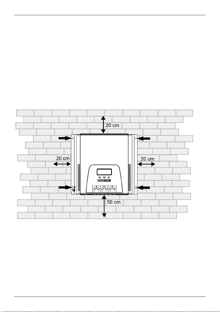
• Unten angegebene Freiflächen einhalten, um die Belüftung des Geräts sicherzustellen.
• Umgebungstemperatur und Luftfeuchtigkeit gemäß den technischen Daten einhalten
(siehe Kapitel 10).
• Um die Sicht auf das Display zu ermöglichen, Gerät etwa auf Augenhöhe montieren.
• Montageort so wählen, dass die Leitungslängen zu Solarmodul, Batterie und Verbrau-
cher möglichst kurz sind.
Montageort mit Freiraum für Belüftung
1. Gerät in Montageposition bringen.
2. Position der Montagebohrungen durch die vier Befestigungsbohrungen am Geräterah-
men anzeichnen.
3. Vier Montagebohrungen in Montagefläche bohren (Ø 5 mm).
4. Gerät abhängig von der Art der Montagefläche mit geeignetem Befestigungsmaterial
befestigen.
10
Page 11

DE
Gerät-Aus-
System-
Aderquerschnitt
Anzieh-
Batterie-
Elektrischer Anschluss
Die Anschlüsse zu den Solarmodulen müssen mit Leitungsschutzschaltern oder Lasttrennschaltern ausgeführt sein. Die Anschlüsse zu den Batterien müssen mit einer Sicherung
oder einem Leitungsschutzschalter ausgeführt sein. Es dürfen keine Wechselrichter am
Lastausgang angeschlossen werden.
Empfohlene Aderquerschnitte, Anziehdrehmomente und Batterie-Leitungsschutzschalter:
führung
spannung
drehmoment
Leitungsschutzschalter
Batterie: 16 mm²
12 V
Solarmodul: 16 mm²
Last: 16 mm²
30 A
1,2 Nm 40 A
Batterie: 6 mm²
24 V
Solarmodul: 6 mm²
Last: 6 mm²
Batterie: 16 mm²
12 V
Solarmodul: 25 mm²
Last: 16 mm²
Batterie: 6 mm²
50 A
Solarmodul: 6 mm²
2 Nm 60 A 24 V
Last: 6 mm²
Batterie: 6 mm²
48 V
Solarmodul: 6 mm²
Last: 2,5 mm²
Die empfohlenen Aderquerschnitte gelten für folgende angenommene Entfernungen zum
Gerät:
• 2 m zur Batterie
• 10 m zum Solarmodul
• 5 m zur Last
Bei stark abweichenden Entfernungen müssen die Aderquerschnitte angepasst werden.
Es wird von folgenden Solarmodul-Spannungen ausgegangen:
• 30 V für 12 V Systemspannung
• 60 V für 24 V Systemspannung
• 90 V für 48 V Systemspannung
11
Page 12
DE
Die Anziehdrehmomente gelten für die Klemmschrauben aller elektrischen Anschlüsse am
Gerät. Die angegebenen Werte für den Batterie-Leitungsschutzschalter sind rechnerische
Maximalwerte. Das bedeutet: Der eingesetzte Batterie-Leitungsschutzschalter muss spätestens bei Erreichen dieser Stromstärke auslösen.
Empfohlen wird ein zweipoliger Leitungsschutzschalter zwischen Solarmodul und Solarladeregler.
Damit können die Solarmodule spannungsfrei am Solarladeregler angeschlossen oder
vom Solarladeregler getrennt werden und es entstehen an den Klemmen keine Lichtbögen.
HINWEIS
Wenn das Solarmodul an die Batterieanschlüsse angeschlossen wird, kann
der Solarladeregler beschädigt werden.
Leitungen korrekt anschließen.
Vor dem Anschließen durch Spannungsmessung an den Leitungen die kor-
rekte Polarität sicherstellen.
Damit der Solarladeregler korrekt funktioniert, die im Folgenden beschrie-
bene Anschlussreihenfolge einhalten.
Bei der Deinstallation in umgekehrter Reihenfolge vorgehen.
1. Sicherstellen, dass alle Leitungen zum Solarladeregler durch die geöffnete Trennein-
richtung (Solarmodul-Trennschalter bzw. Batteriesicherung) spannungsfrei sind.
2. Alle Leitungen auf der Anschluss-Seite abisolieren und ggf. mit Aderendhülsen verse-
hen:
- Ausführung 30 A: 10 mm
- Ausführung 50 A: 18 mm
12
Page 13
DE
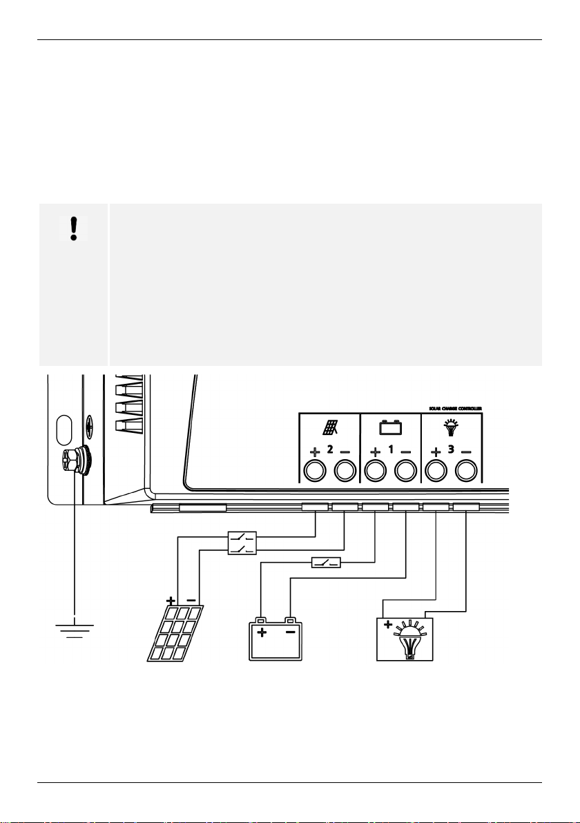
der Solarmodule, der Batterie oder des Lastausgangs geerdet werden.
3. Nacheinander die Adern in die Schraubklemmen des Solarladereglers einführen und
Klemmschrauben festziehen.
4. Plus-Leitung (+) der Batterie am Batterie-Plus-Eingang des Solarladereglers anschlie-
ßen.
5. Minus-Leitung (-) der Batterie am Batterie-Minus-Eingang des Solarladereglers an-
schließen.
6. Plus-Leitung (+) des Solarmoduls am Solarmodul-Plus-Eingang des Solarladereglers
anschließen.
7. Minus-Leitung (-) des Solarmoduls am Solarmodul-Minus-Eingang des Solarladereg-
lers anschließen.
8. Plus-Leitung (+) des Verbrauchers am Verbraucherkreis-Plus-Eingang des Solarlade-
reglers anschließen.
9. Minus-Leitung (-) des Verbrauchers am Verbraucherkreis-Minus-Eingang des Solarla-
dereglers anschließen.
10. Erdungskabel (mindestens AWG 8/10 mm²) am Erdungsanschluss des Solarladereg-
lers anschließen.
HINWEIS
Es darf maximal einer der Minuspole oder einer der Pluspole der Anschlüsse
6 Bedienung
HINWEIS
Vor dem Einschalten muss eine Batterie angeschlossen sein. Der Solarladeregler funktioniert nicht, wenn ein Solarmodul, aber keine Batterie angeschlossen ist.
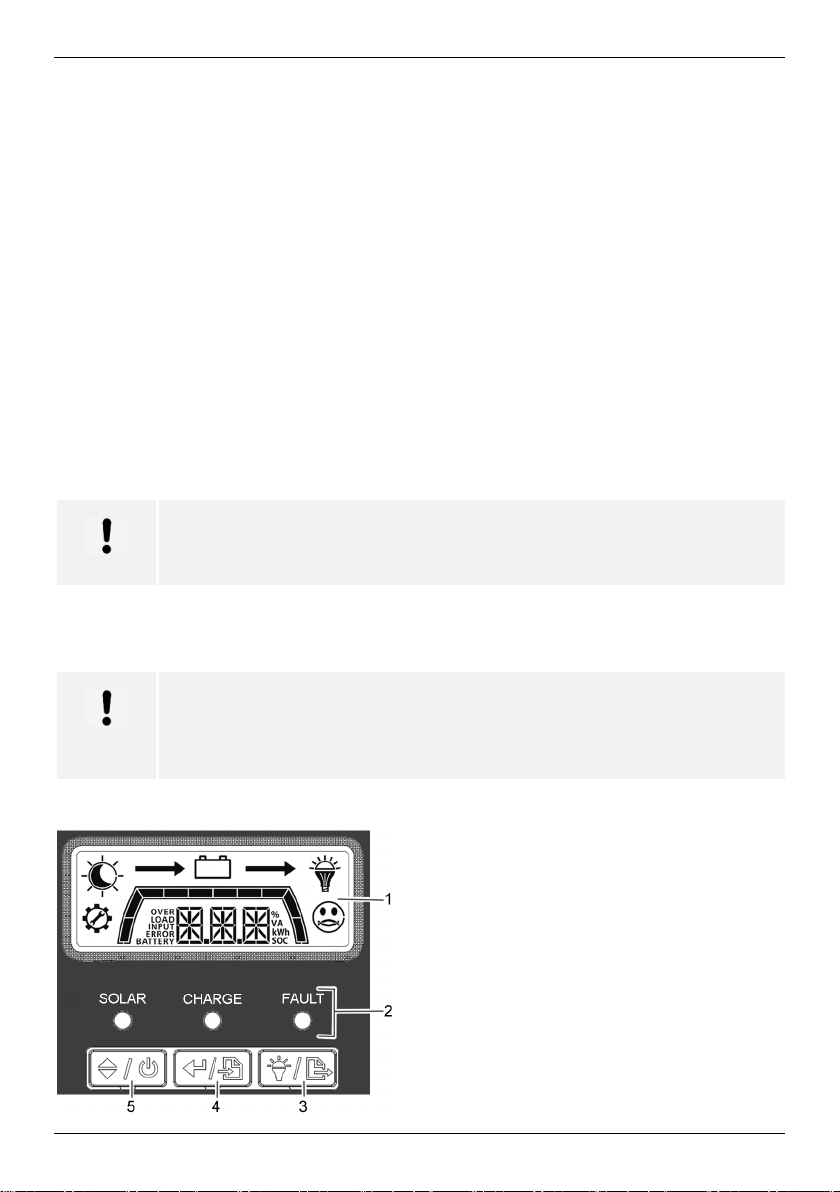
Das Bedienpanel besteht aus dem Display, drei LEDs und drei Tasten:
1 Display
2 LEDs
13
3 Taste "Last Ein/Aus & ESC"
4 Taste "Enter & Einstellungsmenü aufrufen"
5 Taste "Aufwärts/Abwärts & Ein/Aus"
Page 14
DE
LED
Farbe
Zustand
Bedeutung
Taste
Funktion
Bedeutung
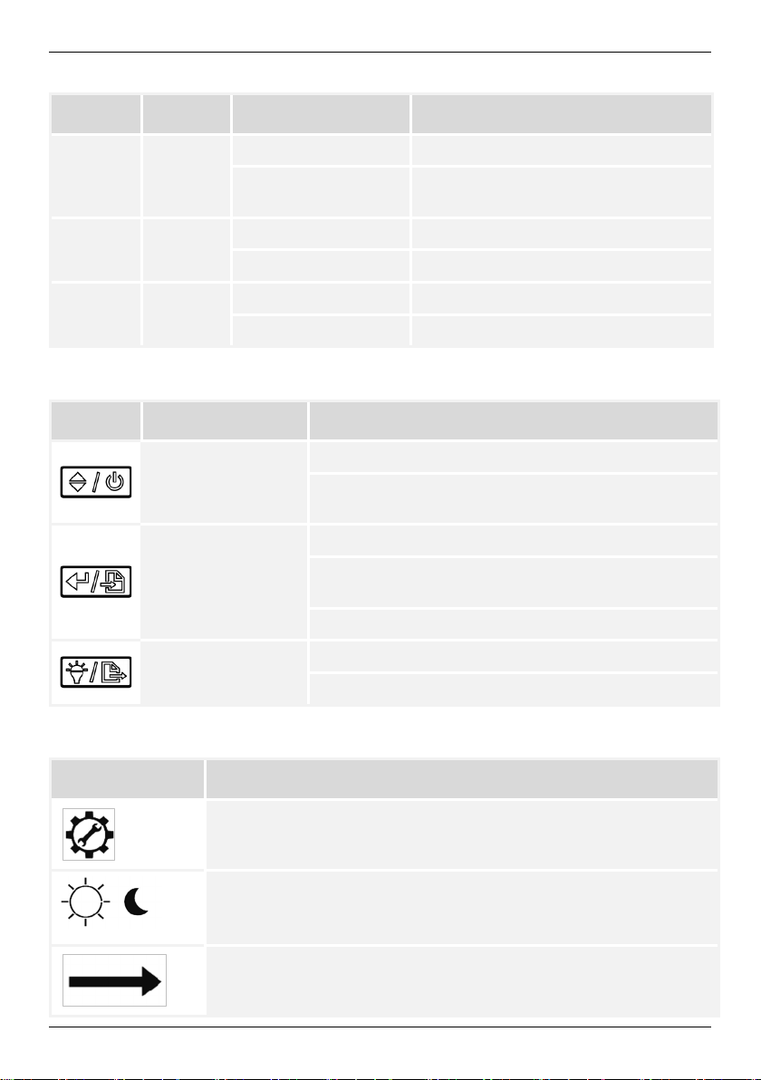
Symbol
Bedeutung
Bedeutung der LEDs:
SOLAR Grün
Leuchtet dauerhaft Eingang Solarmodul normal
Aus
Eingang Solarmodul spannungsfrei
oder fehlerhaft
CHARGE Grün
FAULT Rot
Funktion der Tasten:
Aufwärts/Abwärts &
Ein/Aus
Enter &
Einstellungsmenü
aufrufen
Last Ein/Aus & ESC
Symbole auf dem Display:
Leuchtet dauerhaft Batterie ist vollständig geladen
Blinkt Batterie wird geladen
Blinkt Fehler
Aus Solarladeregler arbeitet normal
Nächste Anzeige auswählen
Solarladeregler ein- und ausschalten, wenn kein Input
vom Solarmodul anliegt
Auswahl im Programmmodus bestätigen
In Programmmodus wechseln oder zur Hauptseite
springen
Fehler quittieren
Lastkreis manuell ein- und ausschalten
Einstellungsmenü verlassen
Anzeigemodus Programmeingabe
Tag-Nacht-Anzeige
Wenn kein Input vom Solarmodul kommt, wird das Mondsymbol
angezeigt
Zeigt Stromfluss an
14
Page 15
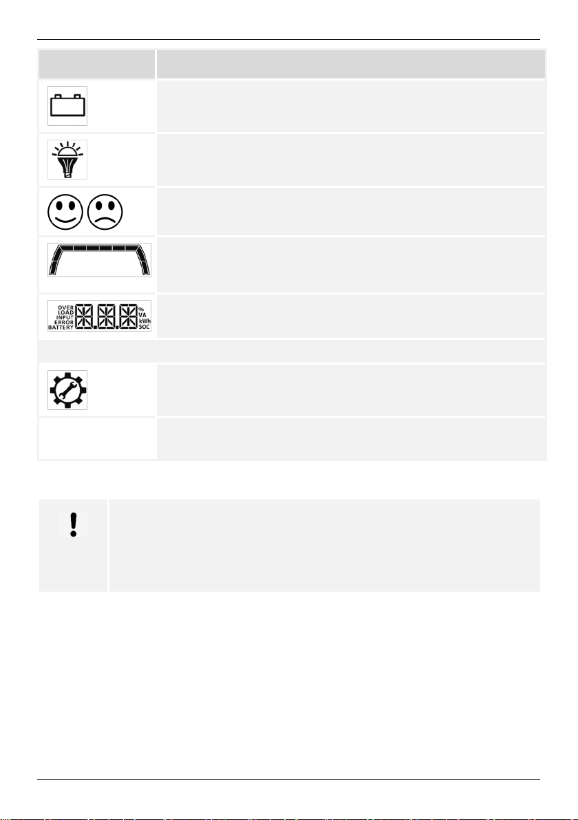
Symbol
Bedeutung
Batterie
Verbraucher
Normalbetrieb/Störung
Grad der Batterieladung
Wenn alle Balkensegmente schwarz sind, ist die Batterie vollständig
geladen
Textanzeige/Werte/Einheit
Anzeige bei Programmeingabe und Störung
Zeigt die Programmnummer an
ERROR XX Blinkt mit Code für Warnung
Leuchtet dauerhaft mit Code für Störung
DE
6.1 Einschalten/Ausschalten
HINWEIS
Der Solarladeregler startet selbsttätig, wenn eine ausreichend hohe Spannung vom Solarmodul anliegt und eine Batterie angeschlossen ist.
Unabhängig von der Solarleistung kann der Solarladeregler auch manuell
ein- und ausgeschaltet werden.
1. Sicherung zur Batterie einschalten.
2. Taste "Aufwärts/Abwärts & Ein/Aus" drücken. Auf dem Display wird die Hauptseite an-
gezeigt. Die Hauptseite zeigt im Wechsel die Batteriespannung und den Ladezustand
der Batterie an.
3. Lasttrennschalter zum Solarmodul einschalten. Wenn die Sonne scheint, beginnt der
Solarladeregler die Batterie zu laden.
15
Page 16
DE
Anzeige
Bedeutung
Anzeige
Bedeutung
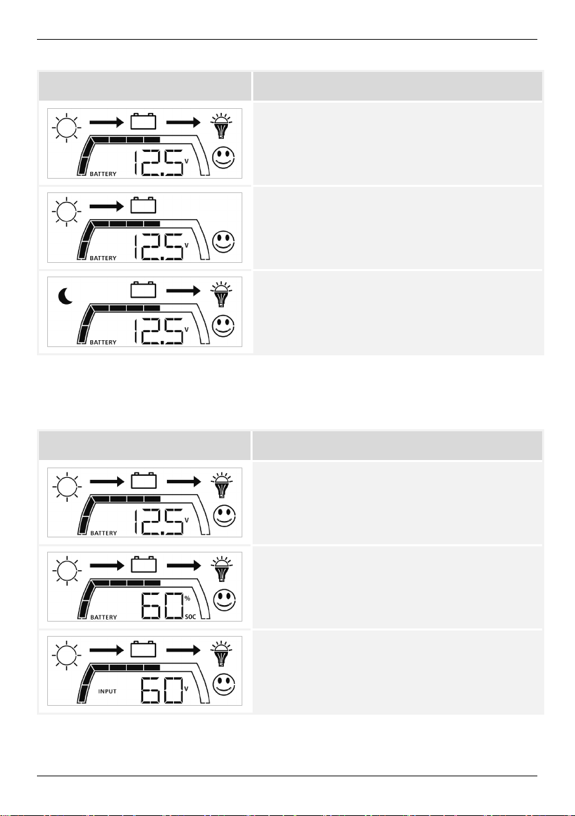
Beispiele für Betriebszustände:
Solarmodule arbeiten, Batterie wird geladen
Verbraucher ist eingeschaltet
Solarmodule arbeiten, Batterie wird geladen
Kein Verbraucher ist eingeschaltet
Kein Input vom Solarmodul
Verbraucher wird mit Batteriestrom betrieben
6.2 Umschalten der Anzeige:
Taste "Aufwärts/Abwärts & Ein/Aus" wiederholt drücken. Es werden nacheinander folgende Informationen angezeigt (die Werte in den Abbildungen sind beispielhaft):
Batteriespannung (Hauptseite)
(hier: 12,5 V)
Batterieladezustand
(hier: 60 %)
Solarmodul-Spannung
(hier: 60 V)
16
Page 17
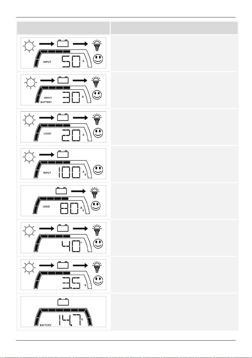
Anzeige
Bedeutung
Eingangsstrom vom Solarmodul
(hier: 50 A)
Ladestrom oder Entladestrom (negativ) Batterie
(hier: 30 A)
Laststrom Verbraucher
(hier: 20 A)
Gesamt-Eingangsleistung
(hier: 100 Ah)
DE
Gesamt-Ausgangsleistung
(hier: 80 Ah)
Gerätetemperatur (innen)
(hier: 40 °C)
Betriebsstunden
(hier: 3,5 h)
Maximale aufgetretene Batteriespannung
(hier: 14,7 V)
17
Page 18
DE
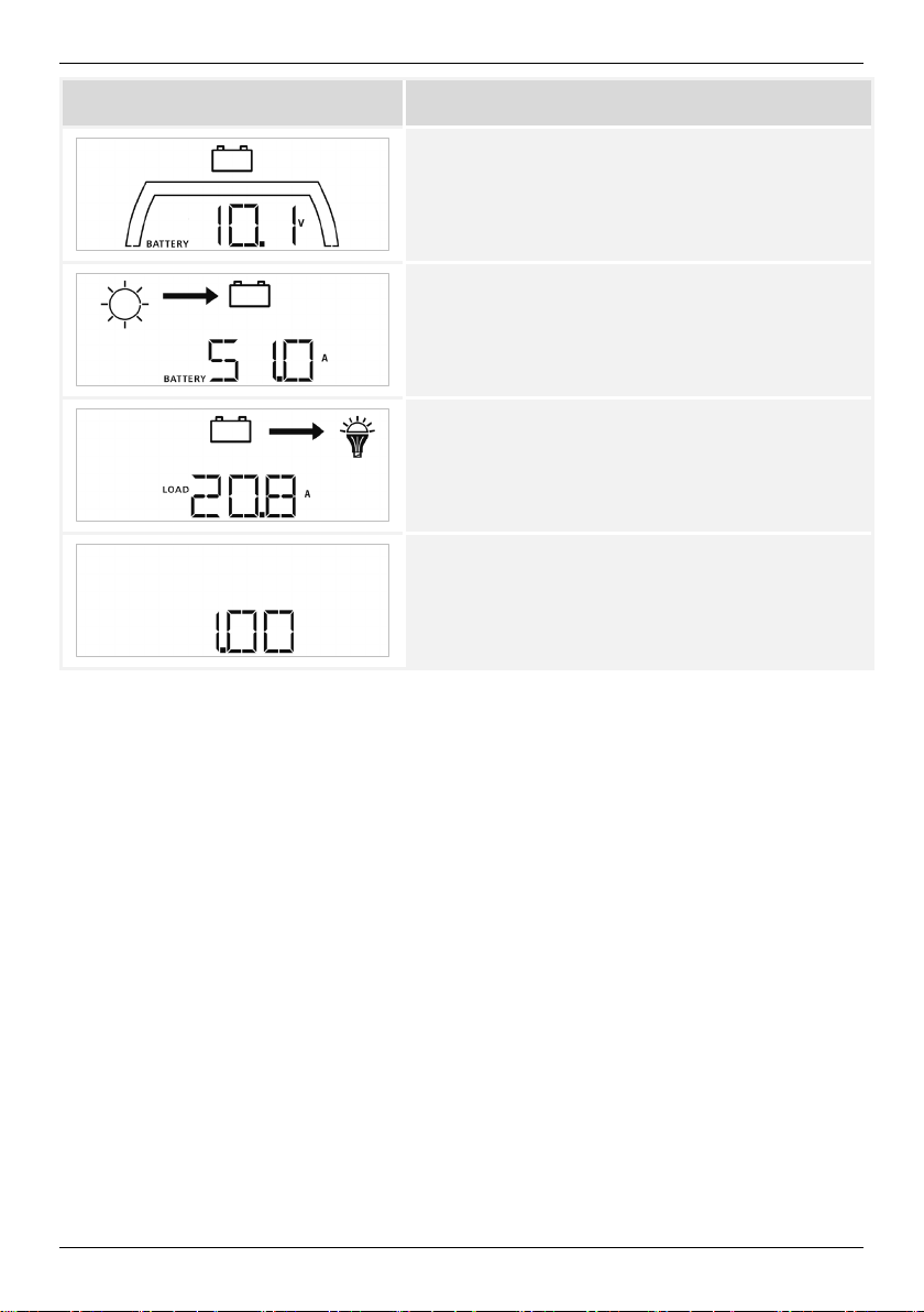
Anzeige
Bedeutung
Minimale aufgetretene Batteriespannung
(hier: 10,1 V)
Maximal aufgetretener Ladestrom
(hier: 51,0 A)
Maximal aufgetretener Entladestrom (= Laststrom)
(hier: 20,8 A)
Firmware-Version
(hier: 1.00)
Anschließend wird wieder der Hauptbildschirm angezeigt.
6.3 Einstellungsmenü
1. Taste "Enter & Einstellungsmenü aufrufen" drücken und 3 Sekunden gedrückt halten.
Der Solarladeregler wechselt damit in den Anzeigemodus Einstellungsmenü.
Wenn nach ca. 20 Sekunden keine weitere Eingabe erfolgt, springt die Anzeige auf
die Hauptseite zurück.
2. Taste "Aufwärts/Abwärts & Ein/Aus" wiederholt drücken, um ein Programm anzuwäh-
len. Der aktuell gewählte Menüpunkt blinkt.
3. Taste "Enter & Einstellungsmenü aufrufen" drücken, um das angewählte Programm
auszuwählen.
4. Taste "Aufwärts/Abwärts & Ein/Aus" drücken, um den gewünschten Einstellwert zu
wählen (angezeigter Wert blinkt).
5. Taste "Enter & Einstellungsmenü aufrufen" drücken, um den gewünschten Wert zu be-
stätigen (angezeigter Wert blinkt nicht mehr).
Alternativ Taste "Last Ein/Aus & ESC" drücken, um den Wert nicht zu übernehmen
und in das Einstellungsmenü zurückzukehren.
6. Taste "Last Ein/Aus & ESC" drücken, um zum Einstellungsmenü zurückzukehren.
18
Page 19
DE
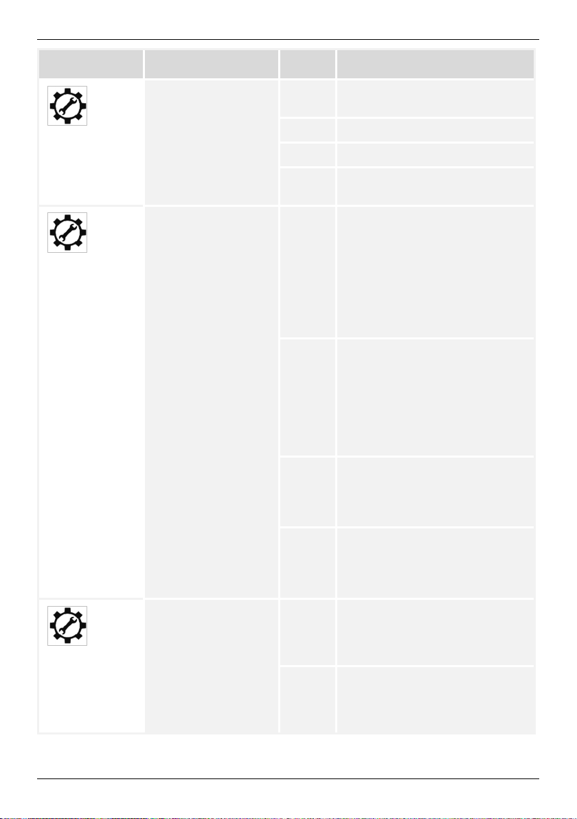
Programmwahl
Name
Option
Bedeutung
01
02
Einstellung
Batteriespannung
Auswahl Batterietyp GEL
AUT
12.0 Batteriespannung 12 V einstellen
24.0 Batteriespannung 24 V einstellen
48.0
FLD Blei-Säure-Batterie (Standard)
LIO Lithium-Ionen-Batterie
Batteriespannung wird
automatisch erkannt
Batteriespannung 48 V einstellen
(nur bei 50-A-Ausführung)
Bleibatterie GEL/AGM
(Standard)
Die Spannungswerte werden für
diesen Batterietyp automatisch
eingestellt
Programme 04 und 06 können
nicht genutzt werden, wenn
diese Einstellung gesetzt ist
Die Spannungswerte werden für
diesen Batterietyp automatisch
eingestellt
Programme 04 und 06 können
nicht genutzt werden, wenn
diese Einstellung gesetzt ist.
Wenn diese Einstellung gesetzt
ist, müssen Programm 04 und 06
angepasst werden
USE Benutzerdefinierte Werte
Wenn diese Einstellung gesetzt
ist, müssen Programm 04 und 06
angepasst werden
Maximaler Ladestrom 50 A
03
30 A
19
Nur für 50-A-Ausführung:
Maximaler Ladestrom 50 A, kann
von 5 A bis 50 A in Schritten von
5 A eingestellt werden
Nur für 30-A-Ausführung:
Maximaler Ladestrom 30 A, kann
von 5 A bis 30 A in Schritten von
5 A eingestellt werden
Page 20
DE
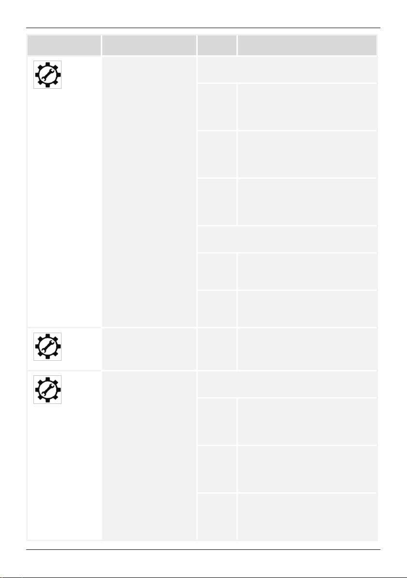
Programmwahl
Name
Option
Bedeutung
04
05
Spannung der
Wartungsladung
Dauer der
Wartungsladung
Wenn "USE" im Programm 01 gewählt ist,
kann dieses Programm verwendet werden
14.4 V
28.8 V
57.6 V
Wenn "LIO" im Programm 01 gewählt ist,
kann dieses Programm verwendet werden
28.8 V
57.6 V
120
12-V-Nennspannung:
Kann von 12,0 V bis 16,0 V
eingestellt werden
(Voreinstellung 14,4 V)
24-V-Nennspannung:
Kann von 24,0 V bis 32,0 V
eingestellt werden
(Voreinstellung 28,8 V)
48-V-Nennspannung:
Kann von 48,0 V bis 64,0 V
eingestellt werden
(Voreinstellung 57,6 V)
30-A-Ausführung:
Kann von 9,0 V bis 32,0 V
eingestellt werden
50-A-Ausführung:
Kann von 9,0 V bis 64,0 V
eingestellt werden
Kann von 10 min bis 900 min in
Schritten von 5 min eingestellt
werden (Voreinstellung 120 min)
Spannung für
Schwebeladung
06
20
Wenn "USE" im Programm 01 gewählt ist,
kann dieses Programm verwendet werden
14.1 V
28.2 V
56.4 V
12-V-Nennspannung:
Kann von 12,0 V bis 16,0 V
eingestellt werden
(Voreinstellung 14,1 V)
24-V-Nennspannung:
Kann von 24,0 V bis 32,0 V
eingestellt werden
(Voreinstellung 28,2 V)
48-V-Nennspannung:
Kann von 48,0 V bis 64,0 V
eingestellt werden
(Voreinstellung 56,4 V)
Page 21

Programmwahl
Name
Option
Bedeutung
Wenn "LIO" im Programm 01 gewählt ist,
kann dieses Programm verwendet werden
DE
07
08
Funktion
Ausgleichsladung
Spannung für
Ausgleichsladung
28.2 V
56.4 V
EQE
EQD
Wenn "USE" im Programm 01 gewählt ist,
kann dieses Programm verwendet werden
15.0 V
30.0 V
60.0 V
30-A-Ausführung:
Kann von 9,0 V bis 32,0 V
eingestellt werden
50-A-Ausführung:
Kann von 9,0 V bis 32,0 V
eingestellt werden
Funktion Ausgleichsladung
aktivieren
Funktion Ausgleichsladung
deaktivieren
12-V-Nennspannung:
Kann von 12,0 V bis 16,0 V
eingestellt werden
(Voreinstellung 14,1 V)
24-V-Nennspannung:
Kann von 24,0 V bis 32,0 V
eingestellt werden
(Voreinstellung 28,2 V)
48-V-Nennspannung:
Kann von 48,0 V bis 64,0 V
eingestellt werden
(Voreinstellung 56,4 V)
Wenn "LIO" im Programm 01 gewählt ist,
kann dieses Programm verwendet werden
30.0 V
60.0 V
21
30-A-Ausführung:
Kann von 9,0 V bis 32,0 V
eingestellt werden
50-A-Ausführung:
Kann von 9,0 V bis 64,0 V
eingestellt werden
Page 22

DE
Programmwahl
Name
Option
Bedeutung
09
10
11
12
13
Ladestrom für
Ausgleichsladung
Dauer der
Ausgleichsladung
Maximale Dauer der
Ausgleichsladung,
falls die Spannung
der Ausgleichsladung
nicht dauerhaft
erreicht wird
Intervall der
Ausgleichsladung
Ausgleichsladung
starten/stoppen
50 A
30 A
240
300
30d
EEN Ausgleichsladung sofort starten
EDE Ausgleichsladung sofort stoppen
Nur für 50-A-Ausführung:
Maximaler Ladestrom 50 A, kann
von 5 A bis 50 A in Schritten von
5 A eingestellt werden
Nur für 30-A-Ausführung:
Maximaler Ladestrom 30 A, kann
von 5 A bis 30 A in Schritten von
5 A eingestellt werden
Kann von 5 min bis 900 min in
Schritten von 5 min eingestellt
werden (Voreinstellung 240 min)
Kann von 5 min bis 900 min in
Schritten von 5 min eingestellt
werden (Voreinstellung 300 min)
Kann von 1 Tag bis 90 Tage in
Schritten von 1 Tag eingestellt
werden (Voreinstellung 30 Tage)
Unterspannung zur
Trennung des
14
22
Laststroms
(Unterspannungsabschaltung)
11.5 V
23.0
46.0
12-V-Nennspannung:
Kann von 9,0 V bis 12,5 V in
Schritten von 0,1 V eingestellt
werden (Voreinstellung 11,5 V)
24-V-Nennspannung:
Kann von 18,0 V bis 25,0 V in
Schritten von 0,2 V eingestellt
werden (Voreinstellung 23,0 V)
48-V-Nennspannung:
Kann von 36,0 V bis 50,0 V in
Schritten von 0,4 V eingestellt
werden (Voreinstellung 46,0 V)
Page 23

DE
Programmwahl
Name
Option
Bedeutung
15
16
Spannung zum
Wiedereinschalten
des Laststroms nach
Unterspannungsabsc
haltung
Steuerung
Lastausgang
12.5 V
25.0
50.0
ON Ein (Voreinstellung)
OFF
LIG
12-V-Nennspannung:
Kann von 9,0 V bis 12,5 V in
Schritten von 0,1 V eingestellt
werden (Voreinstellung 12,5 V)
24-V-Nennspannung:
Kann von 18,0 V bis 25,0 V in
Schritten von 0,2 V eingestellt
werden (Voreinstellung 25,0 V)
48-V-Nennspannung:
Kann von 36,0 V bis 50,0 V in
Schritten von 0,4 V eingestellt
werden (Voreinstellung 50,0 V)
Lastausgang ist immer
eingeschaltet, außer bei
Unterspannungsabschaltung
Ausschalten durch Drücken der
Taste "Last Ein/Aus & ESC" für
eine Sekunde
Lastausgang ist immer
ausgeschaltet
Einschalten durch Drücken der
Taste "Last Ein/Aus & ESC"
Einschaltzeit des Lastausgangs
wird durch die Einstellungen in
Programm 18 gesteuert
Die Lichtfunktion bezieht sich auf die Zeit von Abend- und Morgendämmerung, die
Sonnenuntergangszeit und Sonnenaufgangszeit genannt wird. Wenn die erfasste PVEingangsspannung kleiner als der Einstellwert im Programm 19 ist, wird dies als
Abenddämmerung betrachtet und die Zeit wird als Sonnenuntergangzeit aufgezeichnet.
Wenn die erfasste PV-Eingangsspannung 5 V höher als der Einstellwert im
Programm 19 ist, wird dies als Morgendämmerung betrachtet und die Zeit wird als die
Sonnenaufgangszeit aufgezeichnet.
23
Page 24

DE
Programmwahl
Name
Option
Bedeutung
17
18
Modus für
Laststeuerung
Einschalt-Dauer für
Lastausgang
EVN Abendlicht
Wenn ausgewählt, wird der
Lastausgang nach
Sonnenuntergang eingeschaltet
und bleibt für eine in
Programm 19 eingestellte Dauer
eingeschaltet
MOR Morgenlicht
Wenn ausgewählt, wird der
Lastausgang vor Sonnenaufgang
eingeschaltet und bleibt für eine
in Programm 19 eingestellte
Dauer eingeschaltet
NIT Nachtlicht (Standard)
Wenn ausgewählt, wird der
Lastausgang die ganze Nacht
lang eingeschaltet, von der
Sonnenuntergangszeit bis zur
Sonnenaufgangszeit unabhängig
von der Einstellung in
Programm 19
480
Kann von 0 min bis 480 min in
Schritten von 5 min eingestellt
werden (Voreinstellung 480 min)
Nur einstellbar, wenn in
Programm 16 "LIG" eingestellt ist
PV-Spannung zur
Bestimmung der
19
20
24
Sonnenauf- und
-untergangszeit
Temperaturkompensation für
Batteriespannung
15.0
30.0
60.0
4
12-V-Nennspannung:
Kann von 10 V bis 80 V in
Schritten von 1 V eingestellt
werden (Voreinstellung 15,0 V)
24-V-Nennspannung:
Kann von 20 V bis 8,0 V in
Schritten von 1 V eingestellt
werden (Voreinstellung 30,0 V)
48-V-Nennspannung:
Kann von 40 V bis 80 V in
Schritten von 0,1 V eingestellt
werden (Voreinstellung 60,0 V)
Kann von 0 mV bis 10 mV in
Schritten von 1 mV eingestellt
werden (Voreinstellung 4 mV)
Page 25

DE
Programmwahl
Name
Option
Bedeutung
21
22
Leitungskompensation
Batteriespannung
Beleuchtung der
Anzeige
0
ON
OFF
AUT
Kann von 0 mV bis 30 mV in
Schritten von 1 mV eingestellt
werden (Voreinstellung 0 mV)
Durch die Kabel zwischen
Solarladeregler und Batterie
entstehen Verluste. Dieser Wert
gleicht die Verluste durch
Verschieben der Spannung aus.
Wenn zum Beispiel 10 mV
angegeben werden, wird die
Ladeschlussspannung pro
Ampere Ladestrom um 10 mV
erhöht. Gleichzeitig wird beim
Entladen pro Ampere dieser
Wert von der Unterspannungsabschaltung (Programm 14)
abgezogen
Beleuchtung ist immer
eingeschaltet
Beleuchtung ist immer
ausgeschaltet
Beleuchtung wird bei
Tastendruck eingeschaltet. Nach
30 Sekunden ohne Eingabe
erlischt die Beleuchtung
Reset auf
Werkseinstellung
RST -
23
Reset GesamtEingangsleistung
RST -
24
Reset GesamtAusgangsleistung
RST -
25
Reset gespeicherte
Maximalspannung
26
25
der Batterie
RST -
Page 26

DE
Programmwahl
Name
Option
Bedeutung
27
28
Reset gespeicherte
Minimalspannung der
Batterie
Reset gespeicherter
Maximal-Ladestrom
der Batterie
Reset gespeicherter
Maximal-Laststrom
RST -
RST -
RST -
29
7 Wartung und Pflege
Das Gerät ist wartungsfrei.
GEFAHR
Elektrische Spannung.
Es besteht Lebensgefahr durch Stromschlag.
Gerät nur mit nebelfeuchtem Tuch reinigen.
Die Pflege des Geräts beschränkt sich auf folgende Maßnahmen:
• Staub entfernen
• Reinigen
Staub mit maximal 2 bar Druckluft von den Kühlrippen des Geräts ablassen.
Leichte Verschmutzung:
Oberfläche des Gehäuses mit nebelfeuchtem Tuch reinigen (klares Wasser verwenden).
Stärkere Verschmutzung:
Oberfläche des Gehäuses mit einem nebelfeuchten Tuch reinigen. Zusätzlich ein Reinigungsmittel (ohne Lösungs- oder Desinfektionsmittel) verwenden, das frei ist von körnigen
oder scharfkantigen Substanzen.
Reinigungsmittelreste entfernen.
26
Page 27

DE
Gerät nicht im Hausmüll entsorgen.
Symbol und
Bedeutung
8 Entsorgung
►
►
Gerät gemäß den örtlichen Richtlinien zur Entsorgung von Elektrogeräten
entsorgen.
9 Störungsbehebung
GEFAHR
Elektrische Spannung.
Bei unsachgemäßen Instandsetzungen können Gefahren für den Anwender
und die Anlage auftreten. Außerdem verfällt der Anspruch auf Gewährleistung.
►
Gerät zur Fehlersuche nicht öffnen und nicht versuchen, Bauteile selbst
auszutauschen.
Wenn das Gerät Störungen oder unerlaubte Betriebszustände erkennt, meldet es diese in
Form von Fehlercodes auf dem Display. Die LED "FAULT" blinkt.
Grundsätzlich kann dabei unterschieden werden, ob nur eine vorübergehende Funktionsstörung vorliegt, z. B. durch Überlastung des Geräts, oder ob eine anhaltende Störung vorliegt.
Bei vorübergehenden Funktionsstörungen blinken folgende Symbole und Fehlercodes:
Fehlercode
ERROR 01 Solar-Eingangsleistung ist zu hoch
ERROR 03 Ladestrom ist zu hoch
ERROR 05 Gerätetemperatur ist zu hoch
ERROR 07 Batteriespannung ist zu niedrig
ERROR 08 Batteriespannung ist zu hoch
ERROR 09 Überlast
27
Page 28

DE
Symbol und
Bedeutung
Angezeigter
Ursache
Behebung
Bei anhaltenden Störungen leuchten folgende Symbole und Fehlercodes:
Fehlercode
ERROR 02 Interner Speicherfehler
ERROR 04 Interner Temperatursensor gestört
ERROR 10 Kurzschluss am Lastausgang
ERROR 26 System- bzw. Batteriespannung nicht erkannt
9.1 Was tun bei Störungen
Fehlercode
01 PV Überspannung Spannung der Solarmodule prüfen
Die Spannung muss kleiner als 100 V für die
30-A-Ausführung und kleiner als 150 V für die
50-A-Ausführung sein
Wenn die Spannung der Solarmodule im
erlaubten Bereich liegt, Service kontaktieren
02
03 Ladestrom zu hoch Gerät neu starten
04
05 Übertemperatur
28
Interner
Speicherfehler
Temperatursensor
gestört
Gerät neu starten
Wenn das Problem weiter besteht, Service
kontaktieren
Wenn das Problem weiter besteht, Service
kontaktieren
Gerät neu starten
Wenn das Problem weiter besteht, Service
kontaktieren
Gerät ausschalten und nach einiger Zeit neu
starten
Wenn das Problem weiter besteht, Service
kontaktieren
Page 29

Angezeigter
Fehlercode
Ursache
Behebung
DE
07
08
09
Batteriespannung
zu gering
Batteriespannung
zu hoch
Lastausgang
überlastet
Batteriespannung messen und Einstellung in
Programm 01 prüfen:
- Wenn eine 12-V-Batterie angeschlossen ist,
muss Programm 01 auf "AUT" oder 12.0 V
eingestellt sein
- Wenn eine 24-V-Batterie angeschlossen ist,
muss Programm 01 auf "AUT" oder 24.0 V
eingestellt sein
Messwert der Batteriespannung und Anzeige am
Gerät vergleichen. Wenn es Abweichungen gibt,
Service kontaktieren
Batteriespannung messen und Einstellung in
Programm 01 prüfen:
- Wenn eine 24-V-Batterie angeschlossen ist,
muss Programm 01 auf "AUT" oder 24.0 V
eingestellt sein
- Wenn eine 48-V-Batterie angeschlossen ist,
muss Programm 01 auf "AUT" oder 48.0 V
eingestellt sein (gilt nur für 50-A-Ausführung)
Messwert der Batteriespannung und Anzeige am
Gerät vergleichen. Wenn es Abweichungen gibt,
Service kontaktieren
Prüfen, ob der Lastausgang überlastet ist
Wechselrichter müssen direkt an die Batterie
angeschlossen werden, sie dürfen nicht über den
Lastausgang betrieben werden
Wenn der Lastausgang überlastet ist,
Verbraucher vom Lastausgang trennen
Wenn das Problem weiter besteht, Service
kontaktieren
10
29
Kurzschluss am
Lastausgang
Prüfen, ob ein Kurzschluss am Lastausgang
vorliegt
Verbraucher vom Lastausgang trennen
Kurzschluss am Lastausgang beheben
Wenn das Problem weiter besteht, Service
kontaktieren
Page 30

DE
Angezeigter
Ursache
Behebung
Fehlercode
26
- Keine Anzeige Taste "Aufwärts/Abwärts & Ein/Aus" drücken
Systemspannung
nicht erkannt
Prüfen, ob die Nennspannung der Batterie mit
dem eingestellten Wert in Programm 01
übereinstimmt; ggf. Wert in Programm 01
anpassen
Gerät neu starten.
Wenn das Problem weiter besteht, Service
kontaktieren
Batterieanschluss prüfen
Wenn das Problem weiter besteht, Service
kontaktieren
10 Technische Daten
Ausführung 30 A 50 A
Mechanik und Umgebung
Abmessungen (B x H x T) 230 x 130 x 80 mm 250 x 230 x 85 mm
Gewicht 1,4 kg 3,2 kg
Umgebungstemperaturbereich
Lagerungstemperatur -40 °C bis 75 °C
0 °C bis 55 °C
Luftfeuchtigkeit (relativ) 0 % bis 90 % RH, nicht kondensierend
Schutzart IP 20
Elektrik
Nennspannung
Eigenverbrauch ˂ 2 W ˂ 3 W
Max. Ladewirkungsgrad > 96 % > 98 %
30
12 VDC oder 24 VDC
(automatische Erkennung)
12 VDC, 24 VDC oder
48 VDC
(automatische Erkennung)
Page 31

Ausführung
30 A
50 A
Eingang Solarmodule
DE
Max. Spannung der
Solarmodule (bei allen am
Installationsort
auftretenden
Temperaturbedingungen)
Max. Ausgangsstrom
Solarmodule
Solarmodul MPPT
Spannungsbereich
Max. nutzbare
Ladeleistung
(Empfehlung: Maximal
20 % mehr als diese
Leistung als SolarAnschlussleistung
wählen)
Batterieladung
Max. Ladestrom 30 A 50 A
Erforderliche
Batteriekapazität
Ladungsstufen 3-stufig, plus periodische Ausgleichsladung:
12 V: 15 VDC bis 80 VDC
24 V: 30 VDC bis 80 VDC
100 VOC 150 VOC
30 A (MPP) 50 A (MPP)
12 V: 15 VDC bis 120 VDC
24 V: 30 VDC bis 120 VDC
48 V: 60 VDC bis 120 VDC
900 W 3000 W
Min. 60 Ah Min. 100 Ah
Hauptladung, Wartungsladung, Schwebeladung
(Bulk-Absorption-Float)
Ladespannung
Wartungsladung
(Nennwert)
Ladespannung
Schwebeladung
(Nennwert)
Lasttrennung bei
Unterspannung
(Nennwert)
Wiedereinschaltung nach
Unterspannung
31
14,4 V / 28,8 V 14,4 V / 28,8 V / 57,6 V
13,9 V / 27,8 V 13,9 V / 27,8 V / 55,6 V
11,5 V / 23,0 V 11,5 V / 23,0 V / 46,0 V
12,5 V / 25,0 V 12,5 V / 25,0 V / 50,0 V
Page 32

DE
Ausführung
30 A
50 A
Lasttrennung bei
Überspannung
Wiedereinschaltung nach
Überspannung
Verbraucherkreis
Max. Laststrom für
Verbraucher
Spannung am
Verbraucherausgang
Verbraucher, die mehr als 20 A benötigen, müssen direkt an die Batterie angeschlossen
werden. Wechselrichter dürfen nicht am Lastausgang angeschlossen werden.
16,5 V / 33,0 V 16,5 V / 33,0 V / 66,0 V
16,0 V / 32,0 V 16,0 V / 32,0 V / 64,0 V
20 A
Entspricht der Batteriespannung
11 Gewährleistung und Garantiebestimmungen
Sie finden die Garantiebedingungen im Internet unter:
www.steca.com/pv-off-grid/warranties
Steca Elektronik GmbH
Mammostraße 1
87700 Memmingen
Germany
T +49-(0)8331-8558-0
F +49-(0)8331-8558-131
www.steca.de
32
Page 33

Solarix MPPT 3020 / MPPT 5020
Installation and operating instructions
EN
764393 | Z01 | 18.43
Page 34

EN
Preface
Thank you for choosing a solar charge controller from our company. Through the use of
solar energy, you significantly help to protect the environment by reducing the pollution of
the atmosphere by the emissions of carbon dioxide (CO
All rights reserved, including those for the translation. No part of this manual may be reproduced in any form without our written consent, nor processed by means of electronic systems.
) and other harmful gases.
2
2
Page 35

EN
Table of contents
1 General information .................................................................... 4
2 Safety instructions ...................................................................... 5
2.1 Labels and symbols .............................................................................................. 6
2.1.1 Safety marks ......................................................................................................... 6
2.1.2 Keywords .............................................................................................................. 6
3 Designated use ............................................................................ 7
4 Overview ...................................................................................... 8
5 Installation ................................................................................... 9
6 Operation ................................................................................... 13
6.1 Switching on / switching off ................................................................................. 15
6.2 Changing the display: ......................................................................................... 16
6.3 Settings menu ..................................................................................................... 18
7 Maintenance and care ............................................................... 26
8 Disposal ..................................................................................... 26
9 Fault correction ......................................................................... 27
9.1 Measures in the event of faults ........................................................................... 28
10 Technical data ........................................................................... 30
11 Commercial and legal guarantee conditions .......................... 32
3
Page 36

EN
1 General information
The solar charge controller is available in two power levels (30 A and 50 A).
The device fulfils the following tasks:
• Optimizing the power yield of the connected solar modules
• Controlling the charging process of the battery
• Monitoring the charge state of the battery
• Connecting and disconnecting the consumers connected to the load output
Characteristics
• Intelligent Maximum Power Point Tracking
• Automatic battery voltage detection
• Three-stage charging process to optimize battery performance
• Maximum efficiency up to 99 %
• Charging current configurable depending on the application
• Support of various battery types
• Backlight
• Data output via serial interface (RS-232)
The state-of-the-art device is equipped with an optimized "Maximum Power Point Tracking
(MPPT)" algorithm and is, thus, able to utilise the maximum available power of the solar
module at any point in time and in a wide range of environmental conditions.
The type plate with the required data related to the device and the manufacturer is attached on the bottom of the right side.
The declaration of conformity is available on the website of the manufacturer.
Scope of delivery
• 1 ea. solar charge controller
• 1 ea. installation and operating instructions
Prior to the installation, check whether the packaging and the device are intact.
4
Page 37

EN
2 Safety instructions
This document is part of the product.
• Read these operating instructions thoroughly and completely prior to installation and
use.
• Keep these operating instructions close the device over the entire lifetime of the device.
• Pass these operating instructions on to every subsequent owner or user of the product.
The installation may only be carried out by a qualified trained electrician.
The solar module and the battery supply voltage to the device even while the device is
switched off. When connecting or disconnecting the solar module or the battery, proceed
precisely as described in the instructions in chapter 5.
Incorrectly connected components can damage the device.
Improper operation can reduce the yields of the solar energy system.
System components can be damaged as well.
If one of the following components is damaged, immediately take the device out of operation and disconnect it from battery and solar module:
• Device (not functioning, visible damage, smoke, penetration of liquid etc.)
• Terminals and connected cables
• Solar module
Do not switch the device on again before it has not been repaired by the dealer or manufacturer, or the damaged cables or solar modules have not been repaired by a specialist.
Do not cover the device.
Follow the following instructions to prevent any risk of fire and explosion:
• Do not use the solar charge controller in a dusty environment, in the proximity of solvents, or where flammable gases and vapours may arise.
• Avoid open fire and light in proximity of the batteries. Avoid sparking.
• Ensure that the room is adequately ventilated.
• Check the charging process regularly.
• Follow the charging instructions of the battery manufacturer.
Do not open the case: There is danger to life! Opening the case will also void any warranty.
Have the device only repaired by a qualified specialist workshop or the manufacturer.
Do not change, remove, nor render illegible the signs and markings attached by the manufacturer.
If connecting an external device that is not described within this document, follow the manufacturer’s instructions. Incorrectly connected devices may cause damage to the solar
charge controller.
5
Page 38

EN
Keyword
Meaning
Do not allow the following persons to operate the device:
• Children
• Persons with reduced physical, sensory or mental capabilities
• Persons that do not possess sufficient experience and knowledge (unless given instruc-
tion on proper use of the device and initial supervision by a person responsible for their
safety)
Follow the safety instructions of the connected battery. The charging voltages and currents
must be set on the solar charge controller in accordance with the battery documentation.
The manufacturer disclaims all responsibility for damages due to solar charge controller
parameters set incorrectly.
Follow the safety instructions of the connected solar module.
Follow the general and national safety and accident prevention regulations.
2.1 Labels and symbols
2.1.1 Safety marks
The following safety marks are used on the device and in these instructions:
Warning sign Nature of the danger
Warning of hazardous voltage
Warning of hazardous area
Follow the instructions
2.1.2 Keywords
The following keywords are used in these instructions:
DANGER
WARNING
NOTE
6
Indicates a hazardous situation which, if not avoided, leads to death or
serious injuries.
Indicates a potentially hazardous situation which, if not avoided, may
lead to death or serious injuries.
Indicates a potentially hazardous situation which, if not avoided, may
lead to damage to property and/or the environment.
Page 39

EN
3 Designated use
The solar charge controller is suitable for photovoltaic (PV) systems, for charging batteries
of a rated voltage of 12 VDC or 24 VDC (50 A version also 48 VDC).
The areas of use include the fields of hobbies and leisure, businesses, commerce, and
small companies.
Installation, putting into operation, and removal of the device may only be carried out by
trained qualified personnel complying with the applicable on-site installation regulations.
The qualified personnel must be acquainted with these operating instructions and follow
the instructions.
The end customer may only carry out the operating functions.
The solar charge controller works with direct current and may not be connected to the
public alternating current grid.
Operation is only allowed indoors.
The solar charge controller is only suitable for controlling solar modules. Do not connect
any other charging sources to the solar charge controller. Otherwise, the solar charge controller and/or the source may be destroyed.
The connected solar modules and batteries must satisfy the stated specifications (refer to
chapter 10).
The solar charge controller is basically suitable for the following types of rechargeable
batteries:
• Lead accumulators with liquid electrolyte
• Sealed lead accumulators; AGM, GEL
• Lithium-ion batteries
NOTE
The operator must ensure that the solar charge controller's settings match
the specifications on the battery's data sheet.
Only lithium-ion batteries may be applied that are equipped with an integrated BMS (Battery Management System) and a safety protective shutdown of the battery in the event of a fault provided that no communication
with the BMS is required.
The respective battery type must be set on the solar charge controller, refer to chapter 6.
The default setting is lead battery GEL/AGM.
Other battery types can be configured. An erroneous configuration may damage the solar
charge controller or the battery. The use of the program function is at the operator's own
responsibility.
7
Page 40

EN
1 Display (LCD)
4 Electrical connections
Disclaimer
Both the compliance with these instructions and the conditions and methods during installation, operation, use, and maintenance of the solar charge controller cannot be supervised
by the manufacturer. Improper performance of the installation may cause property
damages and, subsequently, endanger persons.
Therefore, we assume no responsibility and liability for losses, damages or costs that result
due to incorrect installation, improper operation, usage, and maintenance or in any manner
associated therewith.
We also do not assume any responsibility for infringements of patent rights or infringements of other third-party rights resulting from the use of this solar charge controller.
The manufacturer reserves the right to carry out modifications to the product, technical
data, or installation and operating instructions without prior notice.
Attention: Opening the device, any manipulation and repair attempts, as well as any use
not in accordance with the intended use result in the loss of warranty.
4 Overview
Two versions for different charging currents are available:
• Solar charge controller 30 A
• Solar charge controller 50 A
2 LEDs
3 Buttons
5 Communication interface (for accessories)
6 Earth connection
8
Page 41

EN
Under solar radiation, the solar modules and cables may be energised. There
The solar charge controller optimizes the charging of the battery and its lifetime by means
of a three-stage charging algorithm and a configurable equalizing charge:
Charging stages Description
Bulk charge stage
The battery is charged with the maximum power possible
depending on the input by the solar modules
Absorption stage
Battery charging at a constant voltage. The duration of the
absorption charge is configurable.
Float stage
Trickle charging at a constant voltage. If the battery voltage
drops below the threshold voltage for the float charge, a
switch to bulk charge is performed.
Equalize stage
The equalizing charge regenerates the battery to keep the
capacity loss over the lifetime as low as possible.
The equalizing charge function is controlled via the settings
in the programs 07, 08, 09, 10, 11, 12, and 13. To use the
function, it must have been activated in program 07.
Accessories (not included):
PA WiFi1: WiFi box to link the solar charge controller up with a web portal.
5 Installation
DANGER
Voltage
is the risk of injuries and fire due electrocution and electric discharge.
►
Disconnect the connections from the power sources prior to any work on
the device.
►
Only have specialists carry out any installation work.
►
Only connect the cables to the solar charge controller when it is requested
by the instructions.
9
Page 42

EN
Mounting location:
• Mount only indoors.
• Mount in vertical position on the wall, on concrete or another non-flammable surface.
Mounting materials such as screws and dowels depend on the mounting surface and
are, therefore, not included in the scope of delivery.
• Observe the free space specified below to ensure ventilation of the device.
• Observe the ambient temperature and air humidity specified in the technical data (refer
to chapter 10).
• To allow a clear view of the display, mount the device at about eye level.
• Select mounting location such that the lengths of the cables to the solar module, the
battery, and the consumer are kept as short as possible.
Mounting location with free space for ventilation
1. Place the device in mounting position.
2. Mark the position of the mounting bores through the four fixing holes on the device
frame.
3. Drill the four mounting bores in the mounting surface (Ø 5 mm).
4. Fix the device with fixing materials suitable for the type of mounting surface.
10
Page 43

EN
Device
System
Core cross-section
Tightening
Battery
Electrical connection
The connections to the solar modules must be realised with circuit breakers or disconnectors. The connections to the batteries must be realised with a fuse or a circuit breaker. It is
not allowed to connect inverters to the load output.
Recommended core cross-sections, tightening torques, and battery circuit breakers:
version
voltage
torque
circuit breaker
Battery: 16 mm²
12 V
Solar module: 16 mm²
Load: 16 mm²
30 A
1.2 Nm 40 A
Battery: 6 mm²
24 V
Solar module: 6 mm²
Load: 6 mm²
Battery: 16 mm²
12 V
Solar module: 25 mm²
Load: 16 mm²
Battery: 6 mm²
50 A
Solar module: 6 mm²
2 Nm 60 A 24 V
Load: 6 mm²
Battery: 6 mm²
48 V
Solar module: 6 mm²
Load: 2.5 mm²
The recommended core cross-sections apply to the following presumed distances to the
device:
• 2 m to the battery
• 10 m to the solar module
• 5 m to the load
In the case of considerably different distances, the core cross-sections must be adapted.
The following solar module voltages are assumed:
• 30 V for 12 V system voltage
• 60 V for 24 V system voltage
• 90 V for 48 V system voltage
11
Page 44

EN
The tightening torques apply to the terminal screws of all electrical connections on the device. The values specified for the battery circuit breaker are calculated maximum values.
This means that the battery circuit breaker used must trigger no later than when reaching
this amperage.
It is recommended to use a two-pole circuit breaker between solar module and solar
charge controller.
In this way, the solar modules can be connected to or disconnected from the solar charge
controller without voltage, and no electric arcs will form at the terminals.
NOTE
If the solar module is connected to the battery connections, the solar charge
controller may be damaged.
Connect the cables correctly.
Ensure correct polarity by measurement of voltage on the cables prior to con-
nection.
Observe the connection order described below to ensure correct operation of
the solar charge controller.
Proceed in inverse order for uninstalling.
1. Ensure that all cables to the solar charge controller are without voltage due to the
open isolating device (solar module circuit breaker or battery fuse).
2. Strip all cables on the connection side and provide with ferrules if necessary:
- 30 A version: 10 mm
- 50 A version: 18 mm
12
Page 45

EN
No more than one of the negative terminals or one of the positive terminals of
may be connected to earth.
3. Successively introduce the conductors into the screw-type terminals of the solar
charge controller and tighten the terminal screws.
4. Connect positive cable (+) of the battery to the battery positive input of the solar
charge controller.
5. Connect negative cable (-) of the battery to the battery negative input of the solar
charge controller.
6. Connect positive cable (+) of the solar module to the solar module positive input of the
solar charge controller.
7. Connect negative cable (-) of the solar module to the solar module negative input of
the solar charge controller.
8. Connect positive cable (+) of the consumer to the consumers circuit positive input of
the solar charge controller.
9. Connect negative cable (-) of the consumer to the consumers circuit negative input of
the solar charge controller.
10. Connect earth cable (at least AWG 8/10 mm²) to the earth connection of the solar
charge controller.
NOTE
the connections of the solar modules, of the battery, or of the load output
6 Operation
NOTE
A battery must have been connected prior to switching on. The solar charge
controller does not work if a solar module but no battery is connected.
The operating panel consists of the display, three LEDs and three buttons:
1 Display
2 LEDs
13
3 "Load on/off & ESC" button
4 "Enter & Call settings menu" button
5 "Up/down & On/off" button
Page 46

EN
LED
Colour
Status
Meaning
Button
Function
Meaning
Symbol
Meaning
Meaning of the LEDs:
SOLAR Green
Permanently lit Input Solar module normal
Off
Input Solar module without voltage or
defective
CHARGE Green
FAULT Red
Function of the buttons:
Up/down &
On/off
Enter &
Call settings menu
Load on/off & ESC
Symbols on the display:
Permanently lit Battery is fully charged
Flashing Battery is being charged
Flashing Error
Off
Selecting next visualization
Switching solar charge controller on and off if there is
no input from the solar module present
Confirming selection in the program mode
Going to program mode or jumping to main page
Acknowledging errors
Switching load circuit on and off manually
Leaving settings menu
Solar charge controller is working
normally
Display mode Program entry
Day/night indicator
The moon symbol is shown while there is no input coming from the
solar module
Indicates current flow
14
Page 47

Symbol
Meaning
Battery
Consumer
Normal operation / fault
Level of battery charge
When all segments are black, the battery is fully charged
Text display / values / unit
Display during program entry and fault
Shows the program numbers
ERROR XX Flashing with the code for warning
Permanently lit with code for fault
EN
6.1 Switching on / switching off
NOTE
The solar charge controller starts automatically when a sufficiently high
voltage from the solar module is present and a battery is connected.
The solar charge controller can also be switched on and off manually
independently of the solar power.
1. Switch fuse to the battery on.
2. Press "Up/down & On/off" button. The main page appears on the display. The main
page alternates between displaying the battery voltage and displaying the charge state
of the battery.
3. Switch on the disconnector to the solar module. If the sun is shining, the solar charge
controller starts charging the battery.
15
Page 48

EN
Display
Meaning
Display
Meaning
Examples for operating states:
Solar modules are working, battery is being
charged
Consumer is switched on
Solar modules are working, battery is being
charged
No consumer is switched on
No input from the solar module
The consumer is operated with battery current
6.2 Changing the display:
Press "Up/down & On/off" button repeatedly. The following information is displayed
successively (the values in the figures are examples):
Battery voltage (main page)
(here: 12.5 V)
Battery charge state
(here: 60 %)
Solar module voltage
(here: 60 V)
16
Page 49

EN
Display
Meaning
Input current from the solar module
(here: 50 A)
Charging current or discharging current (negative),
battery
(here: 30 A)
Load current, consumer
(here: 20 A)
Total input power
(here: 100 Ah)
Total output power
(here: 80 Ah)
Device temperature (internal)
(here: 40 °C)
Operating hours
(here: 3.5 h)
Maximum occurred battery voltage
(here: 14.7 V)
17
Page 50

EN
Display
Meaning
Minimum occurred battery voltage
(here: 10.1 V)
Maximum occurred charging current
(here: 51.0 A)
Minimum occurred discharging current
(= load current)
(here: 20.8 A)
Firmware version
(here: 1.00)
Then, the main page is displayed again.
6.3 Settings menu
1. Press "Enter & Call settings menu" button and hold for 3 seconds. The solar charge
controller switches to the display mode Settings menu.
If no entry is made during approx. 20 seconds, the display returns to the main page.
2. Press "Up/down & On/off" button repeatedly to select a program. The currently
selected menu item is flashing.
3. Press "Enter & Call settings menu" button to go to the selected program.
4. Press "Up/down & On/off" button to select the desired setting value (the displayed
value is flashing).
5. Press "Enter & Call settings menu" button to confirm the desired value (the displayed
value is no longer flashing).
Alternatively, press "Load on/off & ESC" button to not accept the value and return to
the settings menu.
6. Press "Load on/off & ESC" button to return to the settings menu.
18
Page 51

EN
Program selection
Name
Option
Meaning
01
02
Setting battery
voltage
Selection of
battery type
AUT
12.0 Setting battery voltage 12 V
24.0 Setting battery voltage 24 V
48.0
GEL
FLD Lead-acid battery (standard)
LIO Lithium-ion battery
The battery voltage is detected
automatically
Setting battery voltage 48 V
(only for 50 A version)
Lead battery GEL/AGM
(standard)
The voltage values are
automatically set for this battery
type
Programs 04 and 06 cannot be
used when this setting is
selected
The voltage values are
automatically set for this battery
type
Programs 04 and 06 cannot be
used when this setting is
selected.
When this setting is selected,
programs 04 and 06 must be
adapted
USE User-defined values
When this setting is selected,
programs 04 and 06 must be
adapted
Maximum
charging current
50 A
03
30 A
19
Only for the 50 A version:
Maximum charging current 50 A,
can be set from 5 A to 50 A in
increments of 5 A
Only for the 30 A version:
Maximum charging current 30 A,
can be set from 5 A to 30 A in
increments of 5 A
Page 52

EN
Program selection
Name
Option
Meaning
04
05
06
Voltage of the
absorption
charge
Duration of the
absorption
charge
Voltage for float
charge
If "USE" has been selected in program 01,
this program can be used
14.4 V
28.8 V
57.6 V
If "LIO" has been selected in program 01,
this program can be used
28.8 V
57.6 V
120
If "USE" has been selected in program 01,
this program can be used
14.1 V
12 V rated voltage:
Can be set from 12.0 V to 16.0 V
(default setting: 14.4 V)
24 V rated voltage:
Can be set from 24.0 V to 32.0 V
(default setting: 28.8 V)
48 V rated voltage:
Can be set from 48.0 V to 64.0 V
(default setting: 57.6 V)
30 A version:
Can be set from 9.0 V to 32.0 V
50 A version:
Can be set from 9.0 V to 64.0 V
Can be set from 10 min to
900 min in increments of 5 min
(default setting: 120 min)
12 V rated voltage:
Can be set from 12.0 V to 16.0 V
(default setting: 14.1 V)
28.2 V
56.4 V
If "LIO" has been selected in program 01,
this program can be used
28.2 V
56.4 V
20
24 V rated voltage:
Can be set from 24.0 V to 32.0 V
(default setting: 28.2 V)
48 V rated voltage:
Can be set from 48.0 V to 64.0 V
(default setting: 56.4 V)
30 A version:
Can be set from 9.0 V to 32.0 V
50 A version:
Can be set from 9.0 V to 32.0 V
Page 53

EN
Program selection
Name
Option
Meaning
07
08
09
Equalizing charge
function
Voltage for
equalizing charge
Charging current
for equalizing
charge
EQE
EQD
If "USE" has been selected in program 01,
this program can be used
15.0 V
30.0 V
60.0 V
If "LIO" has been selected in program 01,
this program can be used
30.0 V
60.0 V
50 A
Activating equalizing charge
function
Deactivating equalizing charge
function
12 V rated voltage:
Can be set from 12.0 V to 16.0 V
(default setting: 14.1 V)
24 V rated voltage:
Can be set from 24.0 V to 32.0 V
(default setting: 28.2 V)
48 V rated voltage:
Can be set from 48.0 V to 64.0 V
(default setting: 56.4 V)
30 A version:
Can be set from 9.0 V to 32.0 V
50 A version:
Can be set from 9.0 V to 64.0 V
Only for the 50 A version:
Maximum charging current 50 A,
can be set from 5 A to 50 A in
increments of 5 A
30 A
Duration of the
equalizing charge
240
10
21
Only for the 30 A version:
Maximum charging current 30 A,
can be set from 5 A to 30 A in
increments of 5 A
Can be set from 5 min to 900 min
in increments of 5 min
(default setting: 240 min)
Page 54

EN
Program selection
Name
Option
Meaning
11
12
13
14
Maximum
duration of the
equalizing charge
in case the
voltage of the
equalizing charge
is not reached
permanently
Interval of the
equalizing charge
Starting/stopping
equalizing charge
Undervoltage for
disconnecting
load current
(under-voltage
cutoff)
300
30d
EEN
EDE
11.5 V
23.0
46.0
Can be set from 5 min to 900 min
in increments of 5 min
(default setting: 300 min)
Can be set from 1 day to 90 days
in increments of 1 day
(default setting: 30 days)
Starting equalizing charge
immediately
Stopping equalizing charge
immediately
12 V rated voltage:
Can be set from 9.0 V to 12.5 V
in increments of 0.1 V
(default setting: 11.5 V)
24 V rated voltage:
Can be set from 18.0 V to 25.0 V
in increments of 0.2 V
(default setting: 23.0 V)
48 V rated voltage:
Can be set from 36.0 V to 50.0 V
in increments of 0.4 V
(default setting: 46.0 V)
Voltage for
switching load
15
22
current on again
after undervoltage cutoff
12.5 V
25.0
50.0
12 V rated voltage:
Can be set from 9.0 V to 12.5 V
in increments of 0.1 V
(default setting: 12.5 V)
24 V rated voltage:
Can be set from 18.0 V to 25.0 V
in increments of 0.2 V
(default setting: 25.0 V)
48 V rated voltage:
Can be set from 36.0 V to 50.0 V
in increments of 0.4 V
(default setting: 50.0 V)
Page 55

EN
Program selection
Name
Option
Meaning
Control of load
output
16
The light function refers to the time of dusk and dawn, called sunset time and sunrise
time. If the detected PV input voltage is lower than the set value in program 19, this is
considered as dusk and the time is recorded as sunset time. If the detected PV input
voltage is 5 V higher than the set value in program 19, this is considered as dawn and
the time is recorded as sunrise time.
Mode for load
control
17
ON On (default setting)
Load output is always switched
on, except in the event of undervoltage cutoff
Switching off by pressing the
"Load on/off & ESC" button for
one second
OFF
LIG
EVN Evening light
Load output is always switched
off
Switching on by pressing the
"Load on/ switching & ESC"
button
Power-on time of the load output
is controlled by the settings in
program 18
If selected, the load output is
switched on after sunset and
remains switched on for the
duration set in program 19
MOR Morning light
If selected, the load output is
switched on before sunrise and
remains switched on for the
duration set in program 19
NIT Night light (standard)
If selected, the load output is
switched on for the entire night,
from the sunset time to the
sunrise time independently of the
setting in program 19
23
Page 56

EN
Program selection
Name
Option
Meaning
18
19
20
21
Power-on
duration for load
output
PV voltage to
define sunrise
and sunset time
Temperature
compensation for
battery voltage
Performance
compensation for
battery voltage
480
15.0
30.0
60.0
4
0
Can be set from 0 min to 480 min
in increments of 5 min
(default setting: 480 min)
Can only be set if "LIG" is set in
program 16
12 V rated voltage:
Can be set from 10 V to 80 V in
increments of 1 V
(default setting: 15.0 V)
24 V rated voltage:
Can be set from 20 V to 80 V in
increments of 1 V
(default setting: 30.0 V)
48 V rated voltage:
Can be set from 40 V to 80 V in
increments of 0.1 V
(default setting: 60.0 V)
Can be set from 0 mV to 10 mV
in increments of 1 mV
(default setting: 4 mV)
Can be set from 0 mV to 30 mV
in increments of 1 mV
(default setting: 0 mV)
The cables between solar charge
controller and battery cause
losses. This value compensates
the losses by shifting the voltage.
If, for example, 10 mV are
specified, the charging end
voltage is increased by 10 mV
per ampere of charging current.
At the same time, this value is
deducted per ampere from the
under-voltage cutoff
(program 14)
24
Page 57

Program selection
Name
Option
Meaning
Display backlight ON Backlight is always switched on
EN
22
23
24
25
26
27
28
Reset to factory
setting
Reset of total
input power
Reset of total
output power
Reset of saved
maximum voltage
of the battery
Reset of saved
minimum voltage
of the battery
Reset of saved
maximum
charging current
of the battery
OFF Backlight is always switched off
AUT
RST -
RST -
RST -
RST -
RST -
RST -
Backlight is switched on when
pressing a button The backlight
will go out after 30 second of
inactivity
Reset of saved
maximum load
29
25
current
RST -
Page 58

EN
Do not dispose of the device in the normal household waste.
7 Maintenance and care
The device is maintenance-free.
DANGER
Voltage.
There is a risk of death by electrocution.
Only clean device with a slightly moist cloth.
The care of the device is limited to the following measures:
• Removing dust
• Cleaning
Remove dust from the cooling fins of the device by using compressed air of a maximum of
2 bar.
Light soiling:
Clean surface of the case with a slightly moist cloth (use clear water).
Heavy soiling:
Clean surface of the case with a slightly moist cloth. In addition, use a cleaning agent without solvents or disinfectants, that does not contain any granular or sharp-edged substances.
Remove any residues of the cleaning agent.
8 Disposal
►
►
Dispose of the device in accordance with the local guidelines for disposal
of electrical equipment.
26
Page 59

EN
Symbol and
Meaning
9 Fault correction
DANGER
Voltage.
In the case of improper repairs, risks for the user and the system may arise.
Any claim to warranty will also be cancelled.
►
Do not open the device fro troubleshooting and do not try to replace components by yourself.
If the device detects faults or impermissible operating states, error codes appear on the
display. The "FAULT" LED is flashing.
You can generally differentiate whether there is a temporary malfunction, e.g. due to overload of the device, or if there is a sustained fault.
In the event of temporary malfunctions, the following symbols and error codes are flashing:
error code
ERROR 01 Solar input power is too high
ERROR 03 Charging current is too high
ERROR 05 Device temperature is too high
ERROR 07 Battery voltage is too low
ERROR 08 Battery voltage is too high
ERROR 09 Overload
In the event of sustained faults, the following symbols and error codes are lit:
Symbol and
Meaning
error code
ERROR 02 Internal memory error
ERROR 04 Internal temperature sensor defective
ERROR 10 Short circuit at the load output
ERROR 26 System or battery voltage not detected
27
Page 60

EN
9.1 Measures in the event of faults
Displayed
error code
01 PV overvoltage Check voltage of the solar modules
02
03
04
05
07
Cause Remedy
The voltage must be lower than 100 V for the
30 A version, and smaller than 150 V for the
50 A version
If the voltage of the solar modules is within the
permitted range, contact the service
Internal memory
error
Charging current
too high
Temperature sensor
defective
Excessive
temperature
Battery voltage too
low
Restart the device
If the problem persists, contact the service
Restart the device
If the problem persists, contact the service
Restart the device
If the problem persists, contact the service
Switch device off and restart after some time
If the problem persists, contact the service
Measure battery voltage and check setting in
program 01:
- If a 12 V battery is connected, "AUT" or 12.0 V
must be set in program 01
- If a 24 V battery is connected, "AUT" or 24.0 V
must be set in program 01
Compare the measured value for the battery
voltage and the display on the device. In the
event of discrepancy, contact the service
08
28
Battery voltage too
high
Measure battery voltage and check setting in
program 01:
- If a 24 V battery is connected, "AUT" or 24.0 V
must be set in program 01
- If a 48 V battery is connected, "AUT" or 48.0 V
must be set in program 01 (only applies to the
50 A version)
Compare the measured value for the battery
voltage and the display on the device. In the
event of discrepancy, contact the service
Page 61

Displayed
error code
Cause
Remedy
EN
09
10
26
- No display Press "Up/down & On/off" button
Load output
overloaded
Short circuit at the
load output
System voltage not
detected
Check if the load output is overloaded
Inverters must be connected directly to the
battery, they must not be operated via the load
output
If the load output is overloaded, disconnect
consumers from the load output
If the problem persists, contact the service
Check if a short circuit is present at the load
output
Disconnect consumers from the load output
Eliminate short circuit
If the problem persists, contact the service
Check if the rated voltage of the battery matches
the set value in program 01; adapt value in
program 01 if necessary
Restart the device.
If the problem persists, contact the service
Check battery connection
If the problem persists, contact the service
29
Page 62

EN
10 Technical data
Version 30 A 50 A
Mechanics and surrounding
Dimensions (W x H x D) 230 x 130 x 80 mm 250 x 230 x 85 mm
Weight 1.4 kg 3.2 kg
Ambient temperature
range
Storage temperature -40 °C to 75 °C
Air humidity (relative) 0 % to 90 % RH, non-condensing
Degree of protection IP 20
Electrical system
Rated voltage
Internal consumption ˂ 2 W ˂ 3 W
Max. charging efficiency > 96 % > 98 %
Input, solar modules
Max. voltage of the solar
modules (under all
temperature conditions at
the installation site)
Max. output current, solar
modules
Solar module MPPT
voltage range
12 VDC or 24 VDC
(automatic detection)
100 VOC 150 VOC
30 A (MPP) 50 A (MPP)
12 V: 15 VDC to 80 VDC
24 V: 30 VDC to 80 VDC
0 °C to 55 °C
12 VDC, 24 VDC, or
48 VDC
(automatic detection)
12 V: 15 VDC to 120 VDC
24 V: 30 VDC to 120 VDC
48 V: 60 VDC to 120 VDC
Max. useful charging
power (recommendation:
select maximally 20 %
more than this power as
solar power input)
30
900 W 3000 W
Page 63

Version
30 A
50 A
Battery charging
Max. charging current 30 A 50 A
Required battery capacity Min. 60 Ah Min. 100 Ah
Charging stages 3-stage, plus periodical equalizing charge:
Bulk-Absorption-Float
EN
Charging voltage,
absorption charge (rated
value)
Charging voltage, float
charge (rated value)
Load disconnect in the
event of undervoltage
(rated value)
Switch-on after
undervoltage
Load disconnect in the
event of overvoltage
Switch-on after
overvoltage
Consumers circuit
Max. load current for
consumers
Voltage at the load output Corresponds to the battery voltage
Consumers that require more than 20 A must be connected directly to the battery.
Inverters must not be connected to the load output.
14.4 V / 28.8 V 14.4 V / 28.8 V / 57.6 V
13.9 V / 27.8 V 13.9 V / 27.8 V / 55.6 V
11.5 V / 23.0 V 11.5 V / 23.0 V / 46.0 V
12.5 V / 25.0 V 12.5 V / 25.0 V / 50.0 V
16.5 V / 33.0 V 16.5 V / 33.0 V / 66.0 V
16.0 V / 32.0 V 16.0 V / 32.0 V / 64.0 V
20 A
31
Page 64

EN
11 Commercial and legal guarantee conditions
Find the warranty terms on internet at:
www.steca.com/pv-off-grid/warranties
Steca Elektronik GmbH
Mammostraße 1
87700 Memmingen
Germany
T +49-(0)8331-8558-0
F +49-(0)8331-8558-131
www.steca.de
32
 Loading...