

Stearns Series 350 Catalog Page
Series 350 Armature Actuated Brakes
BACK TO T ABLE OF CONTENTS
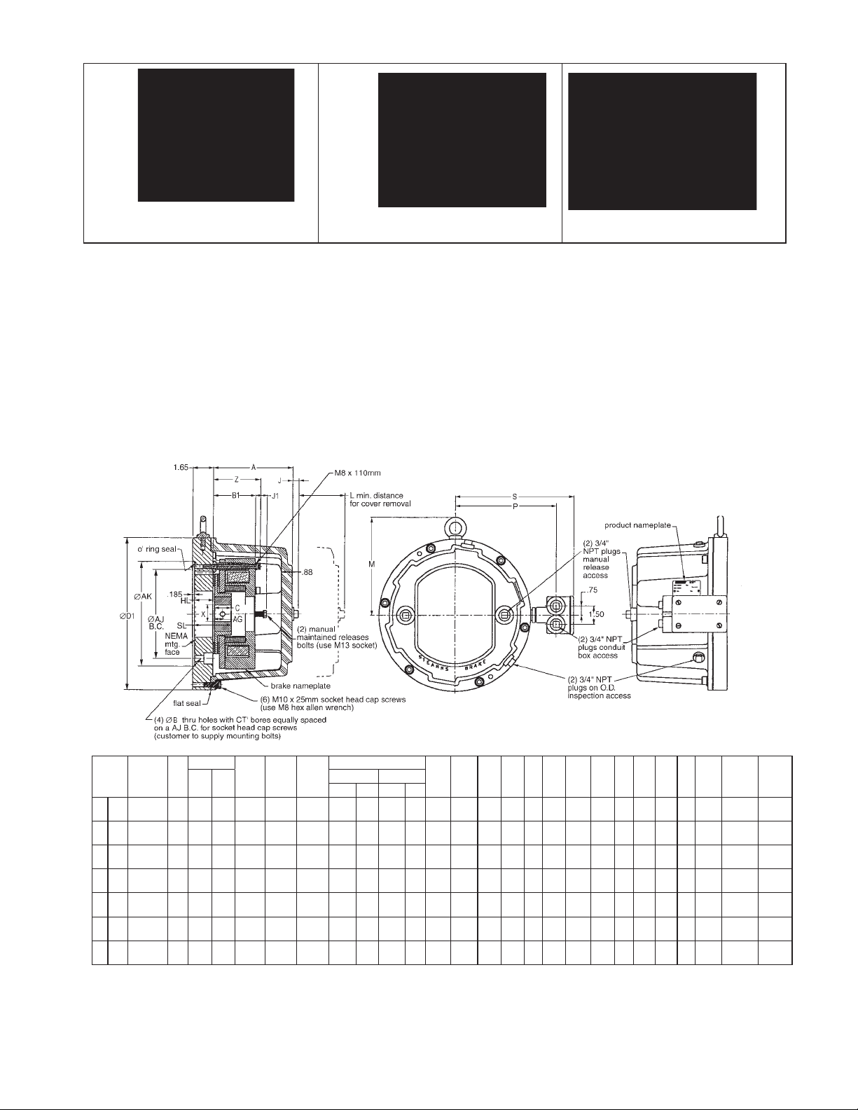
Brake with IP56 Aluminum Cover Brake showing space heater
and release indicator location
Features
• Torque rating 102 - 400 Nm,
75 - 300 lb-ft
• Universal mounting
• Class H insulation
• Maintained manual release
• Corrosion resistance
(stainless steel external hardware)
• IP56 enclosure protection (available
in ductile cast iron or aluminum cover)
• ABS, CSA and CE certification
• Simple wear adjustment with access
hole for air gap inspection
• Metric and US Customary bore sizes
• C-Face mounting - various adapter
plates available for 182TC through
405TSC frame mounting
• Splined hub for quiet dependable
operation
• Installation Instructions/Parts List:
P/N 8-078-895-00
Reverse view showing adapter
mounting plate orientation
Standard Options
• AC rectifier (see pages 86-89)
• Tach/encoder mounting
• Space Heater 115, 230 or
460 Vac
• Thru-shaft
• IEC D and C Flange
• Conduit Box- specify F1 or F2
location (F1 location shown)
F1 Conduit Box location shown.
F2 location on left side facing brake housing.
NEMA
Size
Frame
182TC-
7
196
256TSC
182TC-
7
196
256TSC
284TC-
7
196
286TSC
324TC-
7
196
405TSC
284TC-
8
230
286TSC
324TC-
8
230
405TSC
324TC-
9
278
405TSC
*Key to DIN 6885/3p9-Standard Metric Keyway DIN 6885/1p9
D1** & A** for Aluminum Cover
D1*** & A*** for Ductile Iron Cover
Component Materials:
• Adapter plate - steel (zinc plate)
• Splined hub - steel (zinc plate)
• Splined carrier - aluminum
Torque
B
lb-ft Nm
.53 75 102 7.250 8.500 1/2”-13 1.375 20 1.625 48* 12.38 15.75 3.57 3.97 4.6 8.00 9.68 8.25 .93 6.47 6.73 .50 1.378 1.63
.53 110 150 7.250 8.500 1/2”-13 1.375 20 1.625 48* 12.38 15.75 3.57 3.97 4.6 8.00 9.68 8.25 .93 6.47 6.73 .50 1.378 1.63
.53 110 150 9.000 10.500 1/2”-13 1.375 20 1.625 48* 12.38 15.75 3.57 3.97 4.6 8.00 9.68 8.25 .93 6.47 6.73 .50 1.378 1.63
.66 110 150 11.000 12.500 5/8”-18 1.375 20 1.625 48* 15.75 15.75 3.57 3.97 4.6 9.63 11.38 9.94 .93 6.73 6.73 .50 1.378 1.63
.53 180 240 9.000 10.500 1/2”-13 1.625 25 1.875 50* 15.75 15.75 4.00 4.46 5.0 9.63 11.38 9.94 .93 6.73 6.73 .25 1.575 1.63
.66 180 240 11.000 12.500 5/8”-11 1.625 25 1.875 50* 15.75 15.75 4.00 4.46 5.0 9.63 11.38 9.94 .93 6.73 6.73 .25 1.575 1.63
.66 300 400 11.000 12.500 5/8”-11 1.875 25 2.125 70 15.75 15.75 4.00 5.08 5.0 9.63 11.38 9.94 .97 6.73 6.73 .25 1.969 1.63
AJ AK
Mount
Bolt
• Armature - steel (zinc plate)
• Magnet body - steel (zinc plate)
• Hardware - steel (corrosion resistant
plating or stainless)
X
Min. Bore Max. Bore
in mm in mm
D1** D1*** B1 Z L M S P J1 A** A*** J
• Cover: Size 196 - 182T thru 286TS
NEMA - Aluminum (anodized) (additional
paint optional) Size 196 - 324T thru 405TS
NEMA - Cast Iron (primed) (additional
paint optional)
• Size 230 - 284T thru 405TS NEMA - Cast
Iron (primed ) (additional paint optional)
• Size 278 - 324T thru 405TS NEMA - Cast
Iron (primed) (additional paint optional)
C
Hub
length
HL Hub
Location
AG set
screw
location
.689
17.50
.689
17.50
.689
17.50
.689
17.50
.790
20.07
.790
20.07
.985
25.02
85
Series 350 Continued
Unit Specifications
Size
196
196
196
196
230
230
278
NEMA
Frame
182TC-
256TSC
182TC-
256TSC
284TC-
286TSC
324TC-
405TSC
284TC-
286TSC
324TC-
405TSC
324TC-
405TSC
Nominal
Static Torque
lb-ft Nm Ductile Cast Iron Aluminum Cover
75 102 351-734HX-XX-XX 355-734HX-XX-XX – 103 1800 22
110 150 351-744HX-XX-XX 355-744HX-XX-XX – 103 1800 22
110 150 351-744JX-XX-XX 355-744JX-XX-XX – 103 1800 22
110 150 351-744KX-XX-XX 355-744KX-XX-XX 134 128 1800 22
180 240 351-844JX-XX-XX 355-844JX-XX-XX 208 178 1800 28
180 240 351-844KX-XX-XX 355-844KX-XX-XX 208 178 1800 28
300 400 351-944KX-XX-XX 355-944KX-XX-XX 219 189 1800 30
Part Number Weight/lbs
Ductile
Iron
Aluminum
Max
RPM
BACK TO T ABLE OF CONTENTS
Thermal
Capacity
Hp-Sec/Min
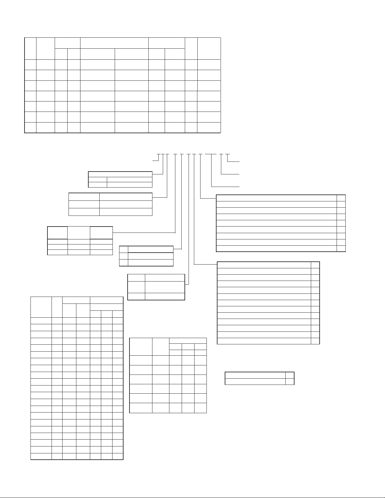
Ordering Information
355-74 4JCOMEA
Part number example:
Group “3” Armature Acting Brake
(Direct acting with a DC Coil)
Mounting Design
Numeral Design
5 Pressure Plate Mount
Brake Cover TypeNumeral
Ductile Iron
1
Aluminum
5
Numeral/
Alpha
7
8
9
Magnet
Body Size
196
230
278
Torque
lb-ft
110
180
300
Torque/Modification
Reduced Torque
43Standard Torque
Table 1 - Hub Bores
NOTE: See page 100 for recommended
minimum bore sizes by torque
Character
to insert
0M
0I
0L
30
38
42
45
48
50
50
55
60
70
* Standard U.S. keyseats made to ANSI B17.1 standard.
Standard metric keyseat DIN 6885/1 p9.
**Keyseat to DIN 6885/3 p9.
86
Keyway Size*
Bore
1.500
1.750
30
38
42
45
48
50**
50
55
60
70
Width
(in.)
5/161.3750G
3/81.6250H
3/8
1/21.8750J
1/22.000
1/22.1250N
—2020
103535
124040
12
14
14
14
14
16
18
20
Depth
(in.)
5/32
3/16
3/16
3/16
1/4
1/4
1/4
Depth
—
3.3
3.3
3.3
3.3
3.3
3.8
3.8
3.8**
3.8
4.3
4.4
4.9
Bores Available
Unit Size
278230196
X
X3/8
X
X
X
X
X
X
X
278230196Metric Bore Width
X
XX8
X
X
X
X10
X
X
X
X
X
X
X
X
X
X
X
X
X
X
Numeral
H
M IP66 conduit box*
*Specify F1 or F2 location
for conduit box modification
Table 2 - Coil Voltage
Character
Insert
Other voltages available - consult factory
For AC rectifiers see pages 86-89
Enclosure
IP66 conduit box*
with terminal strip
Current Rating
Coil
to
Voltage
7 8 9
196 230 278
E 24 Vdc 3.30 4.27 3.85
J 90 Vdc .82 1.05 1.19
K 103 Vdc .75 .96 1.08
L 180 Vdc .42 .54 .61
M 205 Vdc .38 .49 .56
414/432
B
Vdc
.24 .26 .28
Options Table 3
Voltages - Table 2
Hub bore and keyset - Table 1
Additional Options
Standard Brake
Space Heater 115
Space Heater 230 2
Space Heater 460 3
Brake release indicator NO/NC 4
Brake release indicator NO/NC Space Heater 115 5
Brake release indicator NO/NC Space Heater 230 6
Brake release indicator NO/NC Space Heater 460 7
Mounting
HNEMA 180/210/250 C-face
JNEMA 280 C-face
KNEMA 320/400 C-face
NEMA 440 C-face Mt*
NEMA 500 C-face Mt*
IEC 132 C-face Mt*
IEC 160 C-face Mt*
IEC 132 D-face Mt*
IEC 160 D-face Mt*
IEC 180 D-face Mt*
IEC 200 D-face Mt*
IEC 225 D-face Mt*
L
M
S
T
U
V
W
X
Y
*Contact factory for pricing on these mounting options
Table 3 - Additional Options
ANo manual release
RMaintained release (standard)
NOTE: Final part number may change due to
specifications or options selected or other product
design considerations. A number such as a 2, 3, 4 etc.,
in the 12
th
position is used to designate a unique brake
(custom) and can only be assigned by Stearns Design
Engineering Department.
Modifications are available - see AAB Modification
Section.
0
1
 Loading...