

Page 1
C O M M E R C I A L
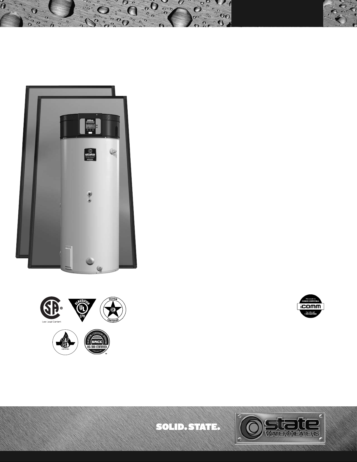
SOLAR GAS BACKUP
INT EGRATED SOLAR & HIG H EFFICIENCY GAS BACKUP
WATER HEATERS
The Solar Gas Backup blends all of the features of the Ultra Force™high
efficiency gas water heater with a storage tank optimized for solar thermal
applications. The integrated space-saving design provides a single tank
solution combining storage for heat captured by solar thermal collectors
with 96% thermally efficient gas backup. This innovative hybrid
technology takes efficiency and performance to their highest levels.
SSF100 120NE and SSX100 120NE
These models are eligible for a 30%
federal tax credit for the total installed
costs (no cap) when installed as part of a
complete commercial or residential solar
thermal hot water system. State and local
incentives may also apply.
SOLAR FEATURES
• Designed for commercial or large
residential with 200-500 gallons daily
hot water usage
• Solar loop side connections - supply and
return from collectors
• Direct and Indirect models
• SSF direct models have open tank
solar loop connections and are
suitable for open loop systems or
closed loop systems using an
external heat exchanger
• SSX indirect models have an integrated
single wall heat exchanger coil and are
suitable for closed loop systems using
Propylene Glycol and distilled water
mixture as the heat transfer fluid
• Combine with our new two, three and
four collector solar package systems that
are SRCC certified OG-300 for a
complete solar hot water system
(package systems available
October 2012)
• Compatible with our integrated
standard and double wall solar
pump stations
• Recirculation loop side connection
• Factory-installed lower tank
temperature sensor for field supplied
solar controls
TANK FEATURES
• 100-gallon storage
• Powered anode rod - maintenance free
protection against corrosion permanent design that does not require
replacement unless damaged
• Commercial grade glasslined tank
provides superior protection
against corrosion.
GAS BACKUP
FEATURES
• Maximum operating set point for the gas
backup burner is 140°F – allows for
optimum solar contribution
• Exclusive State designed control system
provides detailed operational
information, precise temperature control
and built-in diagnostics.
• 96% thermally efficient 120,000 Btu/hr
gas backup burner - available in natural
gas and propane
• Top mounted, down-fired pre-mix
burner provides optimum efficiency and
quiet operation
• Complies with SCAQMD Rule 1146.2
and other Air Quality Management
Districts with similar requirements for
low NOx emissions
• Meets the thermal efficiency and standby
loss requirements of the U.S.
Department of Energy and current
edition of ASHRAE/IESNA 90.1
• Design-certified by CSA International
• iComm
• Conventional power venting or power
• Vents vertically or through sidewall
• Direct vent intake and exhaust pipe can
• Uses inexpensive PVC, CPVC, pipe for
• Flexible venting – uses 3” or 4” pipe –
™
remote monitoring of
the gas heat section.
Call 1.888.WATER02
for more information.
direct venting
terminate separately outside building, or
through single opening, using concentric
vent assembly
intake and exhaust
up to 120 equivalent feet
compatible for
For more information on Solar Gas Backup, contact:
State Water Heaters
500 Tennessee Waltz Parkway
Ashland City, TN 37015
800-365-0024 Toll-free USA
www.statewaterheaters.com
JULY 2012 SCQSS00212
Page 2
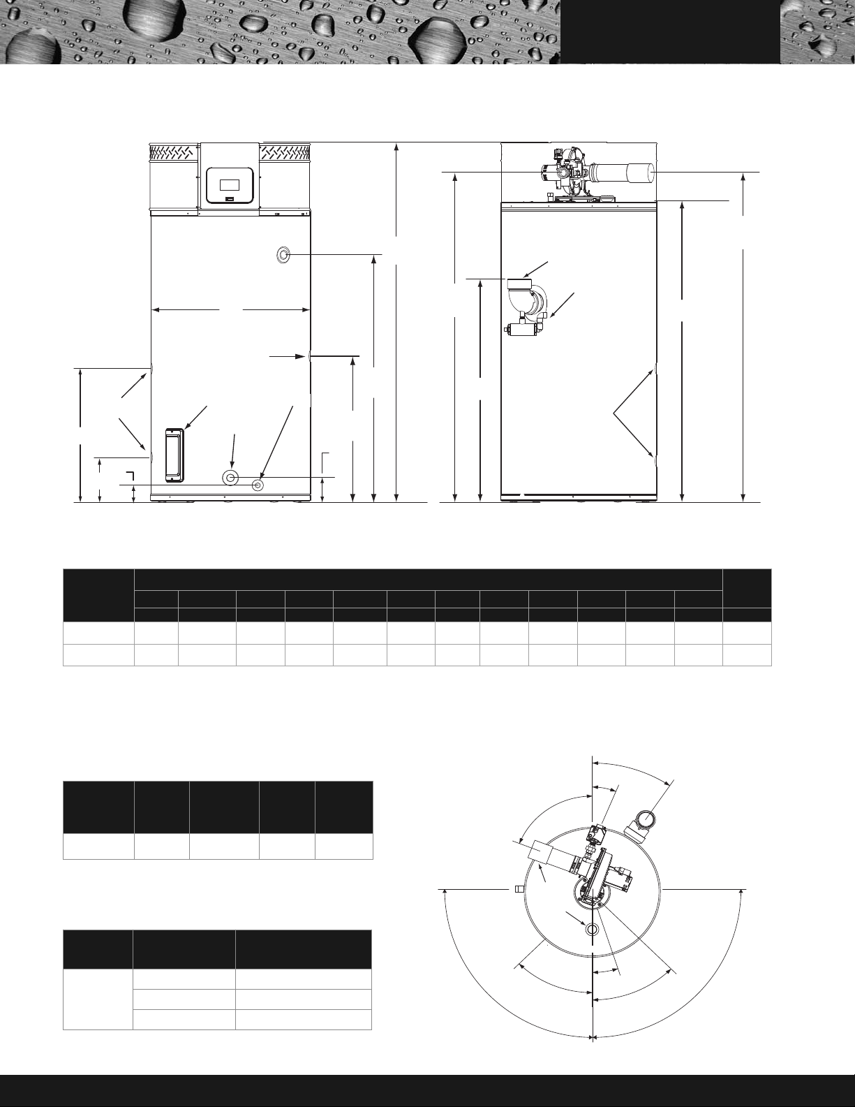
SOLAR GAS BACKUP
FRONT
BACK
CLEANOUT
*SOLAR
LOOP
T & P VALVE
3/4” NPT DRAIN
1 1/2” NPT
WATER INLET
VENT CONNECTION
3 INCH PVC
(exhaust elbow)
CONDENSATE
DRAIN CONNECTION
1/2 INCH PVC
INTAKE AIR CONNECTION
3 INCH PVC
SUPPLY GAS
CONNECTION
*SOLAR
LOOP
E
H
D
L
C
A
J
K
I
G
F
B
WATER OUTLET
HEIGHT
3/4” NPT
RECIRCULATION
LOOP RETURN
* Center line of water outlet on top of the water heaters is approximately 7 inches from the front edge of the water heater.
TOP VIEW
RECIRCULATION LOOP RETURN
90°
90°
SOLAR LOOP
35°
22°
68°
45°
18°
45°
*1 1/2” NPT
WATER
OUTLET
FRONT
INTAKEAIR
3 INCH PVC
GAS
CLEANOUT
DRAIN VALVE
T & P VALVE
VENT
3 INCH
PVC
C O M M E R C I A L
*Solar loop connections are 1 1/2” NPT female on SSF 100 120NE models and 1” NPT female on SSX 100 120NE models.
These designs comply with the current edition of the American National Standard for Gas Water Heaters, Volume III, ANSI Z21.10.3 / CSA 4.3 as an automatic circulating tank water
heater, and automatic storage water heaters.
SHIP
WEIGHT
STD
MODEL
DIMENSIONS
A B C D E F G H I J K L
INCHES/CM INCHES/CM INCHES/CM INCHES/CM INCHES/CM INCHES/CM INCHES/CM INCHES/CM INCHES/CM INCHES/CM INCHES/CM INCHES/CM LBS/KG
SSF100 120NE 3 / 7.62 27.75 / 70.5 6.3 / 16 55.5 / 141 75.5 / 191.8 68.5 / 174 32 / 81.3 63 / 160 69 / 175.3 5.5 / 14 26.5 / 67.3 31.8 / 80.7 535 / 245
SSX100 120NE 3 / 7.62 27.75 / 70.5 6.3 / 16 55.5 / 141 75.5 / 191.8 68.5 / 174 32 / 81.3 63 / 160 69 / 175.3 5.5 / 14 26.5 / 67.3 31.8 / 80.7 568 / 258
Change "N" to "P" in model number for propane.
SSF models have open tank solar loop connections and are suitable for use in open systems or closed systems using an external heat exchanger.
SSX models have an integrated single wall heat exchanger coil in the bottom of the tank and are suitable for closed loop active systems using non-toxic Propylene Glycol and distilled
water mixture as the heat transfer fluid. Glycol used must contain corrosion inhibitors.
SSX MODEL HEAT EXCHANGER COIL DATA
MODEL
NUMBER
TUBE SIZE
I.D.
(inches)
SSX100 120NE 1.63 18.8 4 43.5
Heat exchanger must only be used with a propylene glycol heat transfer fluid
containing corrosion inhibitors such as Dowfrost
Working pressure of the internal heat exchanger coil is 150 PSI.
SURFACE
AREA
(square feet)
CAPACITY
(gallons)
™
.
COIL
TUBE
LENGTH
(feet)
MODEL
NUMBER
SSX100 120NE
SCQSS00212 Page 2 of 6
(gallons per minute)
FLOW RATE
2 0.05
4 0.15
6 0.25
PRESSURE DROP THROUGH COIL
(feet of H2O)
Page 3

SINGLE WALL
HEAT EXCHANGER
COIL - SOLAR LOOP
SOLAR CONTROL TANK
TEMP SENSOR
STANDARD
INTEGRATED SOLAR
PUMP STATION
GAS FIRED BURNER
HEAT EXCHANGER
FINISHED FLOOR
ROOF
COLD WATER
SUPPLY
RECIRCULATION
RETURN OPTIONAL
COLLECTOR TEMP SENSOR
COLLECTORS
SOLAR LOOP
EXPANSION TANK
DOMESTIC WATER
EXPANSION TANK
T
TEMPERED
WATER OUTLET
MIXING VALVE
LEGEND
TEMPERATURE & PRESSURE
RELIEF VALVE
PRESSURE RELIEF VALVE
CIRCULATING PUMP
DRAIN
FULL PORT BALL VALVE
TEMPERATURE GAUGEEXPANSION TANK
CHECK VALVE
MIXING VA LVE
TANK OR LINE TEMPERATURE
CONTROL
T
(NORMALY OPEN
UNLESS OTHERWISE STATED)
TYPICAL APPLICATION SSX-100
C O M M E R C I A L
SCQSS00212 Page 3 of 6
SOLAR SYSTEM PACKAGES
SOLAR SYSTEM
PACKAGE
MODEL
SOLAR GAS
BACKUP
MODEL
NUMBER OF
COLLECTORS
COLLECTOR
SIZE
(FT)
HEAT
EXCHANGER
TYPE
SSC 02ACI202 LC SSX100 120NE 2 3.5' x 7' Single Wall Internal Coil
SSC 03ACI203 LC SSX100 120NE 3 3.5' x 7' Single Wall Internal Coil
SSC 04ACI204 LC SSX100 120NE 4 3.5' x 7' Single Wall Internal Coil
Solar system packages available October 2012
Page 4

FINISHED FLOOR
ROOF
COLD WATER
SUPPLY
COLLECTOR TEMP SENSOR
COLLECTORS
OPEN TANK
SOLAR LOOP
DOUBLE WALL HX
INTEGRATED SOLAR
PUMP STATION
SOLAR CONTROL TANK
TEMP SENSOR
T
SOLAR LOOP
EXPANSION TANK
DOMESTIC WATER
EXPANSION TANK
RECIRCULATION
RETURN OPTIONAL
TEMPERED
WATER OUTLET
GAS FIRED BURNER
HEAT EXCHANGER
MIXING VALVE
TYPICAL APPLICATION SSF-100
LEGEND
TEMPERATURE & PRESSURE
RELIEF VALVE
PRESSURE RELIEF VALVE
CIRCULATING PUMP
DRAIN
FULL PORT BALL VALVE
TEMPERATURE GAUGEEXPANSION TANK
CHECK VALVE
MIXING VA LVE
TANK OR LINE TEMPERATURE
CONTROL
T
(NORMALY OPEN
UNLESS OTHERWISE STATED)
C O M M E R C I A L
SCQSS00212 Page 4 of 6
SOLAR SYSTEM PACKAGES
SOLAR SYSTEM
PACKAGE
MODEL
SSE 02ACE202 LC SSF100 120NE 2 3.5' x 7' Double Wall External Plate
SSE 03ACE203 LC SSF100 120NE 3 3.5' x 7' Double Wall External Plate
SSE 04ACE204 LC SSF100 120NE 4 3.5' x 7' Double Wall External Plate
Solar system packages available October 2012
SOLAR GAS
BACKUP
MODEL
NUMBER OF
COLLECTORS
COLLECTOR
SIZE
(FT)
HEAT
EXCHANGER
TYPE
Page 5

C O M M E R C I A L
INSTALLATION CLEARANCES
REAR WALL
0
0
0
CEILING
FRONT VIEW
TOP VIEW
*Minim um clear ance to r emove t op cover
WATER
HEATER
LEFT
WALL
LEFT
WALL
RIGHT
WALL
RIGHT
WALL
*
1” (2.5 cm)
TOP COVER
SOLAR GAS BACKUP
HEAT INPUT SOLAR LOOP - SOLAR THERMAL COLLECTORS
COLLECTOR MODEL/SIZE
CR-110-AP FLAT PLATE
COLLECTOR (3.5’ X 7’)
Notes: CR-110-AP collector model specification sheet available for download on company website. Contact your local distributor or sales representative
for more information. If other collectors are used in place of CR-110-AP do not exceed maximum Btu/day input above.
COLLECTOR
APERTURE AREA
Square
Feet
Square
Meters
25.5 2.37 25.1 kBtu/day 15.5 kBtu/day 4 100.4 kBtu/day
THERMAL PERFORMANCE
(per collector)
SRCC Data Warm
Climate Clear Day
SRCC Data Cool
ClimateClear Day
MAXIMUM SOLAR THERMAL INPUT
Maximum Number
CR-110-AP Collectors
GAS BACKUP RECOVERY CAPACITY
U.S. GALLONS/HR AND LITRES/HR AT TEMPERATURE RISE INDICATED
MODEL
SSF100 120NE /
SSX100 120NE
Change "N" to "P" in model number for propane.
Recovery capacities are based on heater performance at 96% thermal efficiency.
Maximum gas supply pressure: 10.5” W.C. natural gas 14” W.C. propane.
Electrical requirements: 120 VAC/60Hz, Blower 2.2 Amps FL, Igniter 4.0 Amps.
TYPE OF
GAS
NATURAL/
PROPANE
INPUT
BTUH kW C° 17C° 22C° 28C° 33C° 39C° 44C° 50C° 56C° 61C° 67C° 72C° 78C°
120,000 35 96%
THERMAL
EFFICIENCY
APPROX.
CAPACITY
60 U.S. Gal GPH 461 345 276 230 197 173 154 138 126 115 106 99
227 Litres LPH 1744 1308 1046 872 747 654 581 523 476 436 402 374
Maximum Equivalent Vent Lengths
SSF100 120NE / SSX100 120NE
*NUMBER OF 90°
ELBOWS INSTALLED
One (1) 45 feet (13.7 meters) 115 feet (35.0 meters)
Two (2) 40 feet (12.2 meters) 110 feet (33.5 meters)
Three (3) 35 feet (10.7 meters) 105 feet (32.0 meters)
Four (4) 30 feet (9.1 meters) 100 feet (30.5 meters)
Five (5) ------- 95 feet (29.0 meters)
Six (6) ------- 90 feet (27.4 meters)
3 INCH PIPE 4 INCH PIPE
MAXIMUM FEET (METERS) MAXIMUM FEET (METERS)
F° 30F° 40F° 50F° 60F° 70F° 80F° 90F° 100F° 110F° 120F° 130F° 140F°
MINIMUM SUPPLY GAS LINE SIZE
MODEL NATURAL GAS PROPANE GAS
SSF100 120NE /SSX100 120NE 3/4” NPT 3/4” NPT
Change "N" to "P" in model number for propane.
Maximum
kBtu/day
* Maximum number of 90° elbows allowed for the vent (exhaust) pipe is four (4) when
installing 3 inch pipe and six (6) when installing 4 inch pipe. Maximum number of 90°
elbows allowed for intake air pipe is four (4) when installing 3 inch pipe and six (6) when
installing 4 inch pipe. Two (2) 45° elbows equal one (1) 90° elbow.
SCQSS00212 Page 5 of 6
Page 6

C O M M E R C I A L
OTHER FEATURES
SPACE-SAVING DESIGN FOR INSTALLATION FLEXIBILITY
• Reduced footprint, ease of service, protection from water damage in case of flooding
• Easy to remove top cover for convenient access to serviceable parts
• 0˝ installation clearances on sides and rear, 1-1/2˝ installation clearance on top, 4˝ alcove installation clearance in front Handhole Cleanout of unit
• Handhole cleanout allows easy access to tank interior for cleaning
• 0˝ clearance to combustibles, approved for installation on combustible floors
LIMITED WARRANTY
• Three year tank warranty standard (5 year tank warranty optional)
• One year parts warranty
• For complete warranty details, consult written warranty shipped with heater
INSTALLATION CONSIDERATIONS
1. Condensate Drain – This is a condensing water heater and should be located near a drain to permit proper disposal of condensate.
2. Vent Termination – Exhaust gases of this water heater are less than 140°F. In cold climates water vapor in flue gases will condense into a cloud of vapor where the
vent exits the building.This vapor can gradually discolor exterior building surfaces when terminated through a side wall. The vent termination should be located
where this is not a concern or through the roof to avoid the potential problem. Always locate vent termination above the maximum snowline, and do not locate
vent termination above a walkway.
3. Air Intake – In cold climates, air intake should be located at least four feet from the vent termination of the water heater and any other appliance vents that discharge
moisture-laden air (such as clothes dryers). This will help prevent freeze-over of the intake screen. Air intake should be located above the maximum snowline.
4. Noise – Vent terminal should be located away from bedroom windows or other areas where blower noise will be objectionable.
5. Optional Concentric Vent Kit - Helps to minimize unsightly wall/roof penetrations. Vent kit p/n 9006328005
SAMPLE SPECIFICATION
Water heater shall be State Water Heater model # __________ or equal and shall be an integrated solar thermal __________ (direct/indirect) water heater with a gas fired backup
burner to maintain system temperature during periods when solar energy is not available. The water heater shall have a water storage capacity of 100 gallons. The water heater shall
be fitted with a dedicated recirculation loop connection in the mid portion of the storage tank for applications with hot water building recirculation to maximize solar energy gain
in the lower portion of the tank.
Direct models shall have two open tank solar loop connections in the lower portion of the tank for connection to a solar thermal collector array. Direct models will be compatible
with open loop solar thermal water heating systems or closed loop solar thermal systems with external heat exchangers.
Indirect models shall have an integrated single wall coil type heat exchanger with two solar loop connectionsin the lower portion ofthe tank for connection to a solar thermal collector
array. Indirect models will be compatible with closed loop solar thermal systems using heat transfer fluid containing a mixture of distilled/demineralized water and propylene glycol
with corrosion inhibitors.
The gas fired backup burner shall be fueled by ___________ (Natural/Propane) gas and be 96% thermally efficient with an input rating of 120,000 BTUs per hour, a recovery
rating of 138 gallons per hour (gph) at 100°F rise and a maximum hydrostatic working pressure of 160 PSI. Water heater(s) shall: 1. Have seamlessglasslined steel tank construction,
with glasslining applied to all domestic water-side surfaces after the tank has been assembled and welded; 2. Meets the thermal efficiency and standby loss requirements of the
U. S. Department of Energy and current edition of ASHRAE/IESNA 90.1 3. Have foam insulation and a CSA Certified and ASME rated T&P relief valve; 4. Have a down-fired
power burner designed for precise mixing of air and gas for optimum efficiency, requiring no special calibration on start-up; 5. Be approved for 0˝ clearance to combustibles.
Heater shall be supplied with maintenance-free powered anode.
The control shall be an integrated solid-state temperature and ignition control device with integral diagnostics, graphic user interface, fault history display, and shall have digital
temperature readout.
The water heater(s) shall be: 1. Design certified by CSA; 2. Meets the thermal efficiency and standby loss requirements of the U. S. Department of Energy and current edition
ASHRAE/IESNA 90.1.; 3. Comply with SCAQMD Rule 1146.2 and other air quality management districts with similar requirements for low NOx emissions.
For conventional-vent specification: The water heater(s) shall be suitable for venting in 3˝ PVC pipe for a total equivalent distance of 50 ft and 4˝ PVC pipe for a total equivalent
distance of 120 ft.
For sealed-combustion direct vent specification: The water heater(s) shall be suitable for venting with (3˝ or 4˝) _______ diameter PVC pipe for a total equivalent distance of
(50 ft or 120 ft) ________ feet. [Alternative venting: the heater(s) shall be suitable for sealed combustion direct venting using a (3˝ or 4˝) ________ diameter PVC exhaust pipe
for a total distance of (50 ft or 120 ft) ________ equivalent feet of vent and (50 ft or 120 ft) _______ equivalent feet of intake.]
Operation of the water heater(s) in a closed system where thermal expansion has not been compensated for (with a properly sized thermal expansion tank) will void the warranty.
Water heater should incorporate the iCOMM™ system for remote monitoring of the gas fired backup burner, leak detection and fault alert.
For complete information on limited warranties, consult written warranty or contact
the State Customer Care Center at 1-800-365-0024.
State Industries, Inc., reserves the right to make product changes or improvements without prior notice.
For more information on Solar Gas Backup, contact:
State Water Heaters
500 Tennessee Waltz Parkway
Ashland City, TN 37015
800-365-0024 Toll-free USA
www.statewaterheaters.com
SCQSS00212 Page 6 of 6 © 2012 State Industries, Inc. Printed in U.S.A
 Loading...