

Page 1
SOLAR COLLECTOR SHINGLE ROOF MOUNTING INSTRUCTIONS
CAUTION
ALL PERSONS WORKING ON ROOFS SHOULD
HAVE SUCCESSFULLY COMPLETED A FALL SAFETY
COURSE AND SHOULD BE PROPERLY EQUIPPED
WITH THE APPROPRIATE SAFETY EQUIPMENT
WARNING
AFTER COMPLETION OF THE COLLECTOR
MOUNTING AND PRIOR TO SYSTEM CHARGING THE
COLLECTORS MUST BE COVERED BY A BLANKET OR
OTHER MEANS TO AVOID SOLAR RADIATION FROM
HEATING THE COLLECTORS. THE SURFACES OF THE
COLLECTOR CAN BECOME EXTREMELY HOT AND
COULD POSE A BURN HAZARD.
The most important structural consideration is to securely
anchor the solar collector and the mounting hardware to the
125 Southeast Parkway, Franklin, TN 37068
PHONE: 1-800-433-2545 • FAX: 1-800-433-2515
structural members of the roof with the stainless steel hardware
provided. The solar collector must be attached to the mounting
hardware as detailed in Figure 5.
Preserving the integrity of the roof membrane is the
mostimportantroongconsideration.Ensurethatallroof
penetrations required to plumb and mount the solar collector
areproperlyashedandsealedinaccordancewithstandard
roongpractices.
If the region is subject to hurricane conditions, additional
steps may be required to secure the collector and mounting
hardware to the structural members. In certain areas of the
country, local building codes may require collector wind load
testingorprescribespecicmountingprocedures.Consult
your local building department.
Install the collectors as described in the Spanner Mounting
instructions.
BASIC TOOLS AND MATERIALS
Drill & Drill Bits
Saw (Hand or Circular w/Extension Cord)
Tape Measure
Chalk Line
Utility Knife
Level
Pliers
8” & 10” Adjustable Wrenches
7/16” & 9/16” Wrenches
SPANNER MOUNTING
Although there are other installation methods for mounting
solar collectors, it has been determined that the spanner
mounting method is the most suitable for this application.
Consult with your installer if other mounting means are
required for your installation.
1. After locating the mounting points from Figure 1 for
vertical mounting, Figure 2 for horizontal mounting,
and Table 1, layout the roof as specified and drill 5/16”
holes between the rafters where indicated.
2. Insert the flashing so the top part is under the next row
of shingles and the flashing hole/grommet aligns with
the mounting hole. See Figure 3.
3. The compression bracket washer is positioned over the
flashing seal with the concave side towards the seal.
See Figure 4.
4. The mounting bracket is then placed on the compression
bracket washer.
5. A 12” length of stainless steel 5/16” all-thread is then
inserted through the hole and a stainless steel nut, lock
washer, and EPDM bonded washer secures the allthread to the mounting bracket. The all-thread should
Ratchet
7/16” & 9/16” Sockets
6’ x 8’ or 6’ x 10’ Tarp (1 per collector)
10 linear feet of 2” x 4” or 2” x 6” lumber for spanner
mounting per number of collectors in the system
Installation Hardware (Supplied):
Includes:
• Hardware & Mounting Brackets
extend about 4” below the roof rafters.
6. Fabricate spanners, one for each mounting bracket,
using a 2” x 4” or similar lumber. Spanners must be
long enough to span at least two rafters. In the attic or
crawl space drill a 5/16” hole through each spanner and
insert the all-thread through it. Secure each spanner to
the rafters with decking or wood screws. See Figure 4.
7. Fabricate spacer blocks, one for each mounting bracket,
using a 2” x 4” or similar lumber the same width of the
rafter next to each all-thread. Place spacer blocks next
to the all-thread between the spanner and roof. Secure
each spacer block to the spanners with decking or
wood screws. Spacer blocks are necessary to avoid
deformation of the roof. See Figure 4.
8. With a stainless steel nut, lock washer and fender
washer secure the all-thread to each spanner. Tighten
down until the mounting bracket is tightly secured
to the roof (approx. 97 inch pounds). Be careful not
to overtighten and dish out the roof underneath the
mounting bracket.
9. Repeat steps 2-8 for the remainder of the mounting
bracket locations.
PRINTED 0311 319198-001
1
Page 2
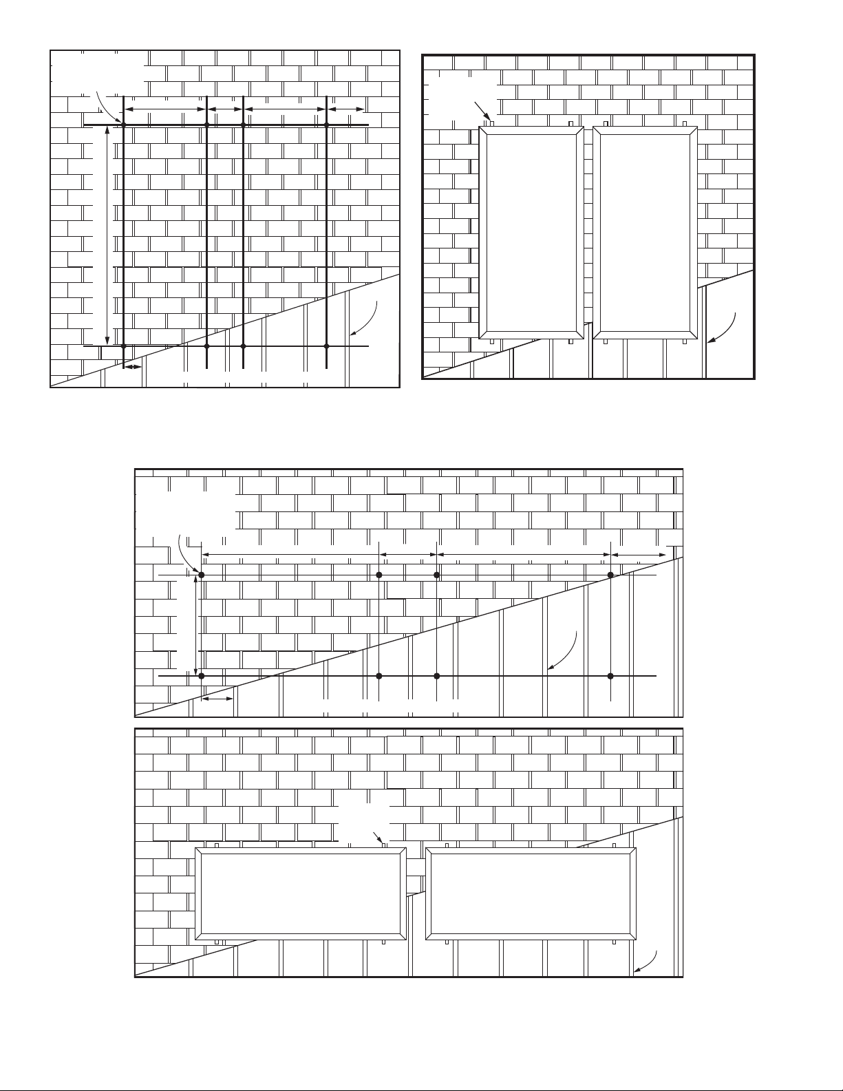
B” B”C”
C”
A”
DRILL POINTS
(CLEARANCE HOLE
for 5/16” BOLT)
RAFTER
D”
BASED ON 16” CENTER RAFTERS
MOUNTING
B” B”C”
C”
A”
DRILL POINTS
(CLEARANCE HOLE
for 5/16” BOLT)
RAFTER
D”
BASED ON 16” CENTER RAFTERS
RAFTER
MOUNTING
BRACKET
RAFTER
BRACKETS
VERTICAL MOUNTING
Figure 1.
RAFTER
HORIZONTAL MOUNTING
Figure 2.
2
Page 3

Flashing
NOTICE
* IF MOUNTING WITH AN OPTIONAL TILT MOUNT
KIT, FOR OPTIMAL COLLECTOR ANGLE REFER TO
ITS INSTRUCTION SHEET FOR THE APPLICABLE “A”
DIMENSION.
COLLECTOR A B C D
Vert. 3.5’ X 7’ 86* 32 14 7-1/4
Vert. 4’ X 8’ 97* 35 16 11-3/4
Vert. 4’ X 10’ 121* 35 16 11-3/4
Horiz. 3.5’ X 7’ 42.25* 62 28 13-1/2
Horiz. 4’ X 8’ 47* 72 28 12
Horiz. 4’ X 10’ 47* 94 30 9
Bushing
Flashing
PLYWOOD
SHEETING
ROOF
RAFTER
DECKING/WOOD
SCREWS
Table 1.
4” MOUNTING BRACKET
FLASHING
WOOD SPANNER
(2” x 4” or 2” x 6” LUMBER)
SPACER
BLOCK
Figure 3.
STAINLESS STEEL NUT, ALL THREAD ROD
LOCK WASHER, & EPDM BONDED WASHER
CP COMPRESSION
BRACKET WASHER
SHINGLES
ROOF
RAFTER
FENDER WASHER
LOCK WASHER
NUT
Figure 4.
3
Page 4

ATTACHING COLLECTOR TO MOUNTING BRACKETS
Once all of the mounting brackets have been secured to
the roof the solar collector(s) can be installed. See Figure
5 for these instructions.
1. Insert the stainless steel channel nut w/spring inside
of the mounting bracket.
2. Fasten the solar collector mounting clip to the channel
nutwiththestainless steelbolt,lock-washer,andat
washer as shown. Do not tighten. Repeat step for the
other mounting bracket locations.
3. The solar collector can now be set on the mounting brackets. To aid in handling the collectors on the
roof the mounting clips may be tightened to the lower
mounting brackets prior to raising the collectors. The
SOLAR COLLECTOR FRAME
STAINLESS STEEL BOLT,
LOCK WASHER,
& FLAT WASHER
MOUNTING CLIP
collector can then be set on the lower mounting brackets while the top clips are fastened over the lip on the
collector frame.
4. After the solar collector is in position, locate the upper
mounting clip so that its lip over-hangs the lip of the
solar collector frame as shown. Tighten the mounting
clip to the solar collector frame securely. Repeat for
the other upper mounting clips.
5. Once the upper mounting clips are secured, the bottom mounting clips can be loosened and retightened
over the collector lip as directed in step 4.
6. Repeat steps as needed for other solar collectors.
STAINLESS STEEL
NUT, ALL THREAD ROD
with LOCK WASHER, &
EPDM BONDED WASHER
CHANNEL NUT with SPRING
(One Piece Part)
MOUNTING
BRACKET
ROOF
FLASHING
CP COMPRESSION
BRACKET WASHER
Figure 5.
4
 Loading...