

Page 1
Commercial Electric Xi Control Instruction Manual
COMMERCIAL ELECTRIC WATER HEATER
MODELS SEV-150 THRU SEV-10000
SEH-200 THRU SEH-10000
UP TO 150KW
500 Tennessee Waltz Parkway
Ashland City, TN 37015
PLACE THESE INSTRUCTIONS ADJACENT TO HEATER AND NOTIFY OWNER TO KEEP FOR FUTURE REFERENCE.
PRINTED 0910 318579-000
Page 2
SAFE INSTALLATION, USE AND SERVICE
Your safety and the safety of others is extremely important in the installation, use, and servicing of this water heater.
Many safety-related messages and instructions have been provided in this manual and on your own water heater to warn you and
others of a potential injury hazard. Read and obey all safety messages and instructions throughout this manual. It is very important
that the meaning of each safety message is understood by you and others who install, use, or service this water heater.
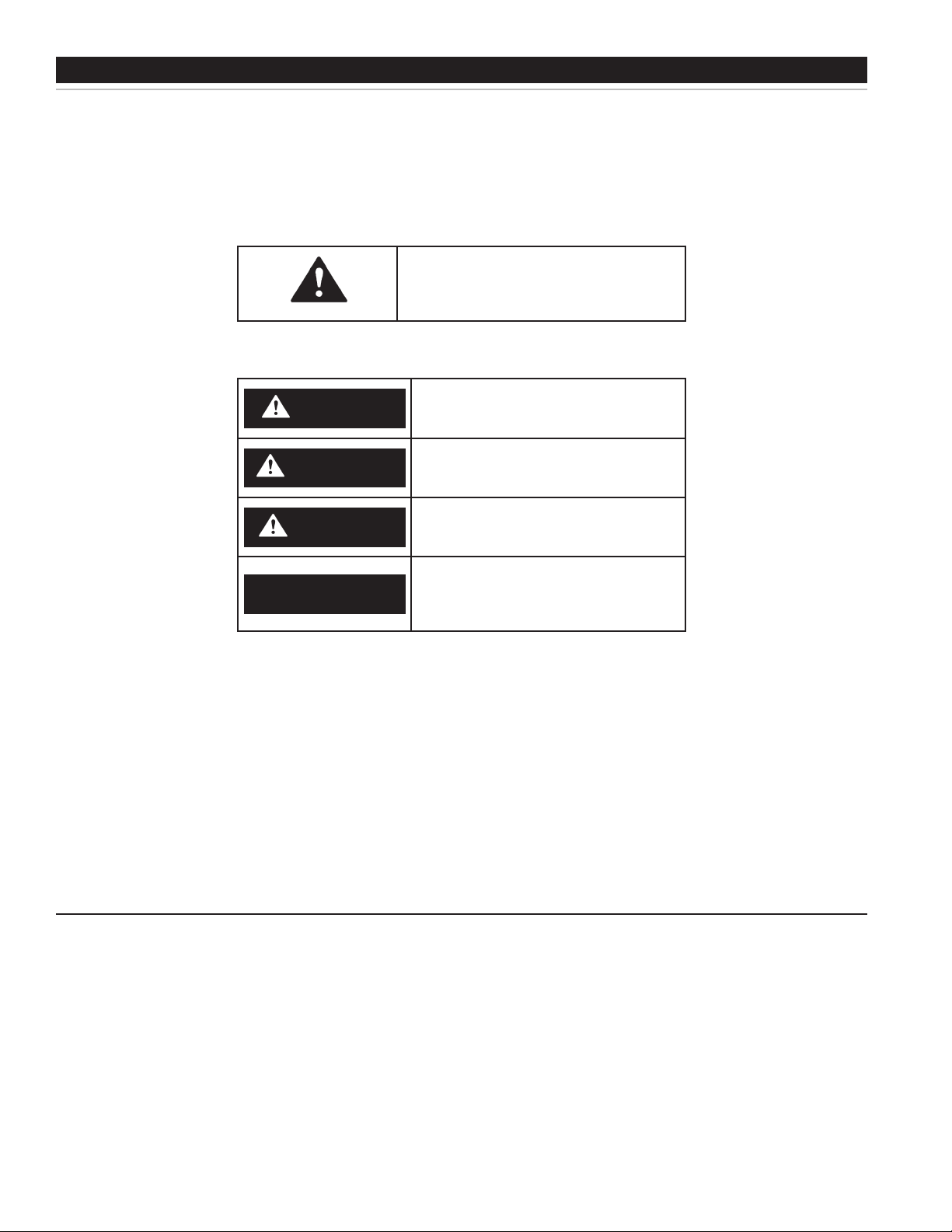
This is the safety alert symbol. It is used to alert
you to potential personal injury hazards. Obey all
safety messages that follow this symbol to avoid
possible injury or death.
DANGER indicates an imminently hazardous
DANGER
WARNING
CAUTION
situation which, if not avoided, will result in
death or injury.
WARNING indicates a potentially hazardous
situation which, if not avoided, could result
in death or injury.
CAUTION indicates a potentially hazardous
situation which, if not avoided, could result
in minor or moderate injury.
CAUTION used without the safety alert
CAUTION
All safety messages will generally tell you about the type of hazard, what can happen if you do not follow the safety
message, and how to avoid the risk of injury.
The California Safe Drinking Water and Toxic Enforcement Act requires the Governor of California to publish a list of
substances known to the State of California to cause cancer, birth defects, or other reproductive harm, and requires
businesses to warn of potential exposure to such substances.
This product contains a chemical known to the State of California to cause cancer, birth defects, or other reproductive
harm. This appliance can cause low level exposure to some of the substances listed.
• QualiedInstallerorServiceAgency:
Installation and service of this water heater requires ability equivalent to that of a Qualied Agency (as dened by ANSI below) in
the eld involved. Installation skills such as plumbing and electrical supply are required in addition to electrical testing skills when
performing service.
symbol indicates a potentially hazardous
situation which, if not avoided, could result
in property damage.
IMPORTANT DEFINITIONS
• ANSIZ223.12006Sec.3.3.83:
“Qualied Agency” - “Any individual, rm, corporation or company that either in person or through a representative is engaged in and is
responsible for (a) the installation, testing or replacement of gas piping or (b) the connection, installation, testing, repair or servicing of
appliances and equipment; that is experienced in such work; that is familiar with all precautions required; and that has complied with all
the requirements of the authority having jurisdiction.”
2
Page 3
GENERAL SAFETY INFORMATION
PRECAUTIONS
DO NOT USE THIS APPLIANCE IF ANY PART HAS BEEN UNDER
WATER. Immediately call a qualied service technician to inspect
the appliance and to replace any part of the control system which
has been under water.
If the unit is exposed to the following, do not operate heater until all
corrective steps have been made by a qualied service agency.
1. External re.
2. Damage.
3. Firing without water.
GROUNDING INSTRUCTIONS
This water heater must be grounded in accordance with the National
Electrical Code and/or local codes. These must be followed in all cases.
Failure to ground this water heater properly may also cause erratic
control system operation on ELECTRONIC CONTROL models.
This water heater must be connected to a grounded metal, permanent
wiring system, or an equipment grounding conductor must be run with
the circuit conductors and connected to the equipment grounding
terminal or lead on the water heater.
When servicing this unit, verify the power to the unit is turned off prior to opening the control cabinet door.
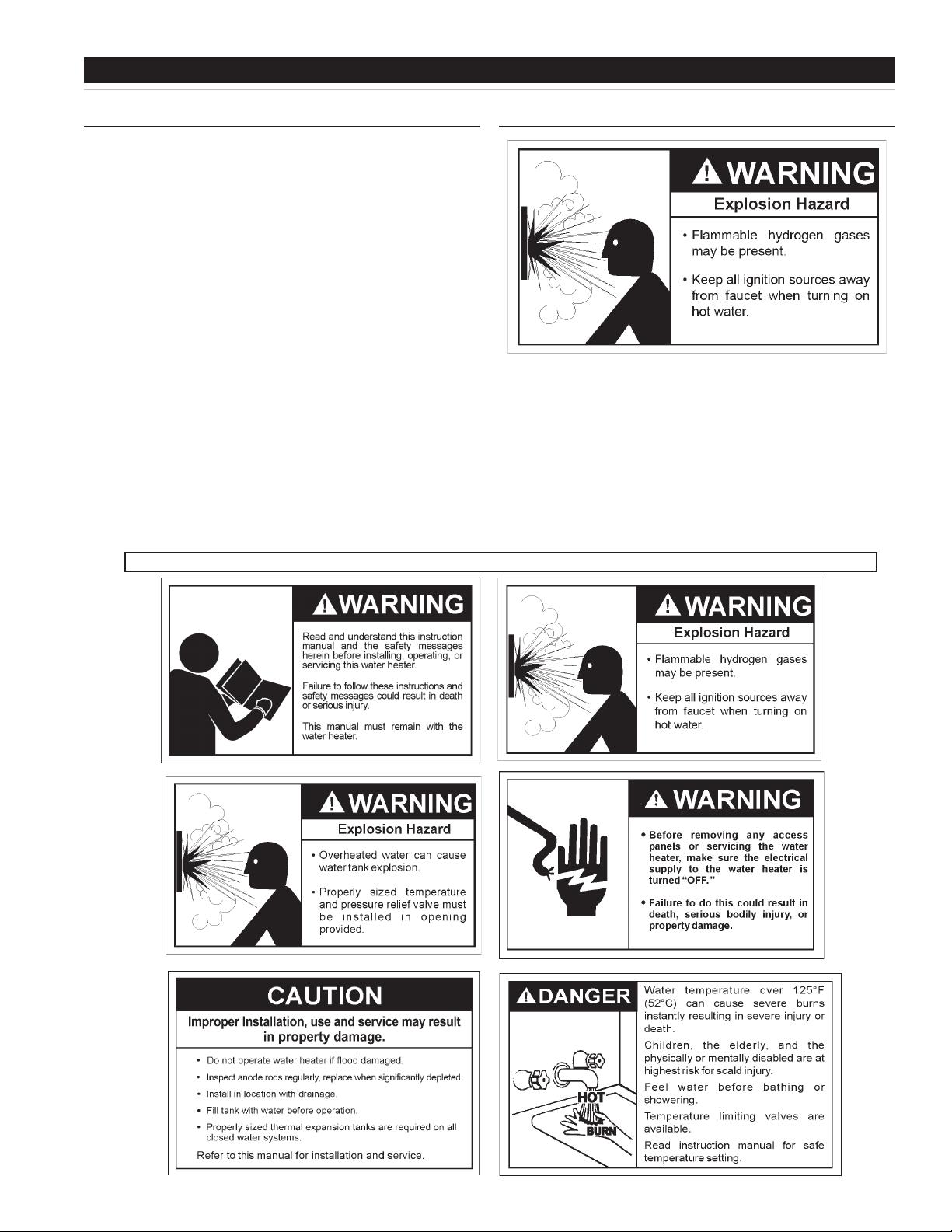
HYDROGEN GAS (FLAMMABLE)
Hydrogen gas can be produced in a hot water system served by this heater
that has not been used for a long period of time (generally two weeks or
more). Hydrogen gas is extremely ammable. To reduce the risk of injury
under these conditions, it is recommended that the hot water faucet be
opened for several minutes at the kitchen sink before using any electrical
appliance connected to the hot water system. If hydrogen is present there
will probably be an unusual sound such as air escaping through the pipe
as the water begins to ow. THERE SHOULD BE NO SMOKING OR
OPEN FLAME NEAR THE FAUCET AT THE TIME IT IS OPEN.
3
Page 4

TABLE OF CONTENTS
This manual contains the operating instructions for the commercial electric Xi control. It is intended to be used in conjunction with
the water heater instruction manual.
SAFE INSTALLATION, USE AND SERVICE........................ 2
GENERAL SAFETY INFORMATION .................................... 3
Precautions ...................................................................... 3
Hydrogen Gas (Flammable) ............................................. 3
INTRODUCTION ..................................................................4
Preparing for the Installation ............................................ 4
ELECTRICAL DATA .............................................................. 5
General ............................................................................ 5
Branch Circuit .................................................................. 5
Heater Circuits ................................................................. 5
Control Circuits ................................................................ 5
Power Circuit .................................................................... 5
WIRING DIAGRAMS ............................................................ 6
TEMPERATURE REGULATION .......................................... 7
High Temperature Limit Controls (ECO) .......................... 7
Thermostat Controls ........................................................ 7
Mixing Valves ................................................................ 7-8
Temperature Adjustment .................................................. 8
CONTROL SYSTEM OPERATION ...................................... 9
INTRODUCTION
Heating Element Operation .............................................. 9
Control System Features ................................................. 9
Control System Navigation .............................................. 9
The Desktop Screen ........................................................ 9
Temperatures Menu ....................................................... 12
Water Heater Status Menu............................................. 14
Economy Mode Settings ...........................................16-18
Alarm Output Setup Menu ............................................. 19
Heater Information Menu ............................................... 19
Current Fault / Alert Menu .............................................. 20
Fault History Menu ......................................................... 20
Fault Occurence Menu ................................................... 20
Restore Factory Defaults Menu ..................................... 21
TROUBLESHOOTING CHECKLIST .................................. 22
Not Enough or No Hot Water ......................................... 22
Water Is Too Hot ............................................................ 22
Water Heater Makes Strange Sounds ........................... 22
Notes .................................................................................. 23
Thank You for purchasing this water heater. Properly installed and
maintained, it should give you years of trouble free service.
Abbreviations Found In This Instruction Manual:
• ANSI - American National Standards Institute
• ASME - American Society of Mechanical Engineers
• NEC - National Electrical Code
• NFPA - National Fire Protection Association
PREPARING FOR THE INSTALLATION
1. Read the “General Safety” section of this manual first
and then the entire manual carefully. If you don’t follow
the safety ru les, the wate r heater may not oper ate safely.
It could cause DEATH, SERIOUS BODILY INJURY AND/
OR PROPE RTY DAMAGE.
Th is manu al cont ai ns in st ructi ons f or the in st all at ion,
ope r a tio n , an d ma i n ten a n ce o f th e wa t er h eate r. It
also co ntains wa rnings throughou t the manu al that you
must read and be aware of. All warnings and all instructions
are e s sent i a l to t he pr o p er op e rati o n of t h e wa t e r
heater and your safety. READ THE ENTIRE MANUAL
BEFORE ATTEMPTIN G TO INSTAL L O R OPERATE THE
WATER HEATER.
Gen era l outl i ne dia gra ms are in th i s m anu a l. Th e se
diagrams will serve to provide the installer with a reference
for basic installation of this product. IT IS NECESSARY
TH AT A LL THE ELECTRICAL WIR IN G BE I NS TAL LE D
AND CONNECTED AS SHOWN IN THE DIAGRAMS.
Be sur e to tu rn off po w er whe n wo rki ng o n or ne ar
the electrical system of the water heater. Never touch
electrica l c omponents wi th we t hands or when standing
in water. When replacing fuses always use the correct
size for the circuit. Use same size and type of fuse
when replacing.
2. T he in st all at ion must con for m with th ese instru ction s
and t he lo cal c od e authorit y having jurisd ic tion and t he
requirements of the power company. In the absence of
code requiremen ts, foll ow NFPA-70 (curre nt edition). The
National Electrical Code may be ordered from: National
Fire Protection Association, 1 Batterymarch Park, Quincy,
MA 02269.
3. If a fter readi ng th is manual you have any que stions or do
not underst and an y portion of the i nstructi ons, call the toll
free num be r on th e back co ver for further a ssistance .
4. Installation and service of this water heater requires ability
equivalent to that of a lic en sed trade sm an or quali fi ed
age ncy (pag e 2) i n t he fie ld in v ol v ed . Plum bin g a nd
electrical work are required.
5. Massachusetts Code requires this water heater to be
in stall ed in a cc ordan ce with M assac hu setts 248 -CMR
2.00: State Plumbing Code and 248-CMR 5.00.
4
Page 5

ELECTRICAL DATA
GENERAL
Check the water heater model and rating plate information against
the characteristics of the branch circuit electrical supply. Do not
connect the heater to an improper source of electricity.
Voltage applied to the water heater should not vary more than +5% to
-10% of the model and rating plate marking for satisfactory operation.
Do NOT energize the branch circuit for any reason before the water
heater tank is lled with water. Doing so may cause the heating
elements to fail.
The installation must conform to these instructions and the local
code authority having jurisdiction. Grounding and electrical wiring
connected to the water heater must also conform to the National
Electrical Code, NFPA 70. This publication is available from The
National Fire Protection Association, 1 Batterymarch Park, Quincy,
MA 02269.
BRANCH CIRCUIT
The branch circuit wire size should be established through reference
to the NEC (National Electrical Code) or other locally approved
sources in conjunction with the water heater amperage rating.. Wire
rated at 75°C should be used. For convenience, portions of the wire
size tables from the Code are reproduced in Table 1 on page 9. It
is suggested the electrician size the branch circuit at 125 percent
of the heater rating and further increase wire size as necessary to
compensate for voltage drop in long runs. Voltage drop should not
exceed 3% at the water heater.
HEATER CIRCUITS
The water heater’s electrical components are pictured and identied
in the Features and Components illustrations in Diagrams 1 and 2.
The model and rating plate provides heater circuit ratings. There are
two main electrical circuits:
Control Circuit: Power supply for the electromagnetic
contactor co ils. 12 0V powe r is supplied to the contac tor coi ls
by the CCB (Central Control Board) see wiring diagrams in
this manual.
Power Circuit: High voltage, single or three phase, circuit that
carries the heating element load.
The following section and pages describe the water heater circuits
and includes wiring diagrams.
CONTROL CIRCUITS
The water heater is equipped with an electronic control system. The
system includes a CCB (Central Control Board) circuit board, an
immersion temperature probe with ECO for temperature sensing and
limiting, a UIM (User Interface Module) for user interface & information
display and element current sensors for monitoring the power circuits.
Refer to the control circuit label on the water heater for details. The
CCB is powered by a small 120V/24V transformer. The control circuit
operates on 120V supplied by a larger 100VA transformer.
Sequence of Operation
1. When the control is powered, the UIM should display model
information, water temperature, operating setpoint, heating
status and operating mode.
2. If the control determines that the actual water temperature inside
the tank is below the programmed operating setpoint minus the
(1st) differential setpoint, a call for heat is activated.
3. After all safety checks are veried the CCB will energize the
contactor coil(s). On models with more than one heating
element the upper most heating elements are energized rst.
Successive heating elements are energized according to
programmed differential setpoints for each heating element.
4. The control remains in the heating mode until the water
temperature reaches the programmed operating setpoint. At
this point the contactors will be de-energized.
5. The control system now enters the standby operating mode
while continuing to monitor the water temperature and the state
of other system devices. If the water temperature drops below
the programmed Operating Setpoint minus the (1st) differential
setpoint, the control will automatically return to step 2 and repeat
the heating cycle.
POWER CIRCUIT
Power circuit wiring is type THHN (or equivalent) rated 600 volts,
105°C, sized as necessary.
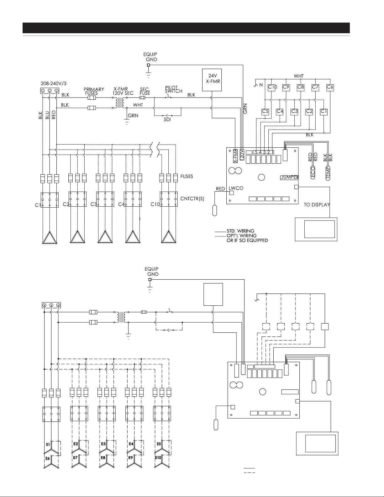
The following wiring diagrams on page 6 are included in this manual
to show typical arrangements of electrical components in the control
and power circuits by voltage and phase characteristics. They are to
be used as a reference by the installer or servicer in performing their
work. An actual diagram of the water heater wiring is furnished with
the water heater.
5
Page 6
WIRING DIAGRAMSWIRING DIAGRAMS
300-600V/3
BLK
BLK WHT
WHT
C5 C4 C3 C2 C1
C5C4C3C2C1
N
GRN
GRN
BLK
BLK
X-FMR
ECO
TEMP
120V
BLK
BLU
RED
RED
RED
RED
SDI
24V
X-FMR
PRIMARY
FUSES
X-FMR
12 0V SEC
SEC.
FUSE
PILOT
SWITCH
BLK
BLK
JUMPER
TO DISPLAY
LWCO
54321
FUSES
CNTCTR(S)
ELEMENT ORDER = E1 THROUGH E10
STD. WIRING
OPT’L WIRING
OR IF SO EQUIPPED
DIAGRAM 1. LARGE COMMERCIAL WIRE DIAGRAM 208-240V / 3PH
DIAGRAM 2. LARGE COMMERCIAL WIRE DIAGRAM 300-600V/3PH
6
Page 7
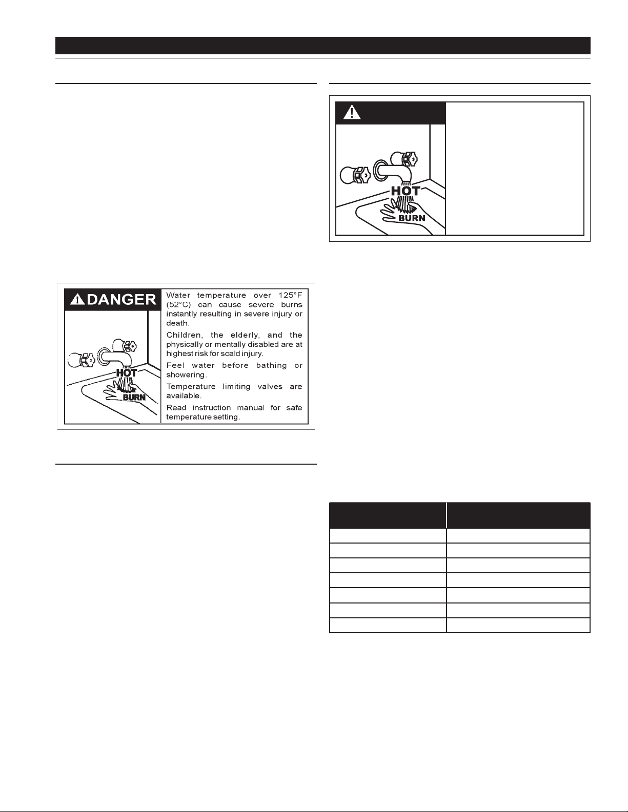
DANGER
Water temperature over 125°F (52°C)
can cause severe burns instantly
resulting in severe injury or death.
Children, the elderly and the physically
or mentally disabled are at highest risk
for scald injury.
Feel water before bathing or showering.
Te mperature limiting devices such as
mixing valves must be installed when
required by codes and to ensure safe
temperatures at fixtures.
Water Te mperature
Time to Produce 2nd & 3rd
Degree Burns on Adult Skin
180°F (82°C) Nearly instantaneous
170°F (77°C) Nearly instantaneous
160°F (71°C) About 1/2 second
150°F (66°C) About 1-1/2 seconds
140°F (60°C) Less than 5 seconds
130°F (54°C) About 30 seconds
120°F (49°C) More than 5 minutes
TEMPERATURE REGULATION
HIGH TEMPERATURE LIMIT CONTROLS (ECO)
This water heater is equipped with an ECO (energy cut off). This
switch is adjustable, up to 190 degree F. An ECO is a normally
closed switch that opens (activates) on a rise in temperature. If the
ECO switch contacts open (activate) due to abnormally high water
temperatures the control system will lock-out and disable further
heating element operation. It is important that a qualied service
agent be contacted to determine the reason for the ECO activation
before resetting the ECO. Once the reason has been determined
and corrected the ECO can be reset as follows:
When the ECO switch contacts open (activate) the electronic control
system locks out and displays a Fault message. Voltage to the
contactor coils and heating elements is terminated to prevent further
heating operation. Should the ECO activate, the water temperature
must drop below 120°F/49°C before the control system can be reset.
Once the water temperature has cooled below this point the power
supply to the water heater must be turned off and on again to reset
the control system.
MIXING VALVES
Water heated to a temperature which will satisfy clothes washing,
dish washing, and other sanitizing needs can scald and cause
permanent injury upon contact. Short repeated heating cycles
caused by small hot water uses can cause temperatures at the
point of use to exceed the water heater’s temperature setting by
up to 20°F (11°C).
Some people are more likely to be permanently injured by hot water
than others. These include the elderly, children, the infirm and the
physically/mentally disabled. Figure 1 shows the approximate time-
to-burn relationship for normal adult skin. If anyone using hot water
provided by the water heater being installed fits into one of these
groups or if there is a local code or state law requiring a certain
water temperature at the point of use, then special precautions
must be taken.
THERMOSTAT CONTROLS
The water heaters covered in this instruction manual are equipped
with adjustable thermostat controls to control water temperature. Hot
water temperatures required for automatic dishwasher and laundry
use can cause scald burns resulting in serious personal injury and/
or death. The temperature at which injury occurs varies with the
person’s age and duration of exposure. The slower response time
of children, the elderly or disabled persons increases the hazards to
them. Never allow small children to use a hot water tap or draw their
own bath water. Never leave a child or disabled person unattended in
a bathtub or shower. The water heater should be located in an area
where the general public does not have access to set temperatures.
Setting the water heater temperatures at 120°F will reduce the
risk of scalds. Some States require settings at specic lower
temperatures.
See Figure 1 which shows the approximate time-to-burn relationship
for normal adult skin.
In addition to using the lowest possible temperature setting that
satises the demand of the application a Mixing Valve should be
installed at the water heater (see Figure 2) or at the hot water taps
to further reduce system water temperature.
Mixing valves are available at plumbing supply stores. Consult a
Qualied Installer or Service Agency. Follow mixing valve manufacturer’s
instructions for installation of the valves.
FIGURE 1.
7
Page 8
HOT WATER
OUTLET
TO TANK
INLET
CHECK
VALV E
MIXING
VALV E
COLD
WATER
INLET
TEMPERED WATER
OUTLET
12” TO 15”
(30-38 cm)
CHECK
VALV E
FIGURE 1.
TEMPERATURE ADJUSTMENT
TEMPERATURE REGULATION
temperature from a factory installed immersion temperature
probe. The “Operating Set Point” is adjusted to control water
temperature. This is an adjustable user setting in the control
system’s “Temperatures Menu.” This and all control system
menus are accessed through the UIM (User Interface Module
located on the front panel of the water heater.
The Operating Set Point is adjustable from 90°F/42 °C to
190°F/88°C. The factory setting is 120°F/49°C. See the Control
System Operation sec tion of this manual for instructions on how
to adjust the Operating Set Point and other user settings.
Set the Operating Set Point at the lowest setting which produces
an acceptable hot water supply. This will always give the most
energy efficient operation.
The water heaters covered in this instruction manual are equipped
with an electronic control system. The control system senses
8
Page 9

CONTROL SYSTEM OPERATION
HEATING ELEMENT OPERATION
ProgressiveSequencing: Elements are energized and de-energized
according to adjustable (1 to 20°F) Differential set points for each element.
Element Rotation - rst element on is rotated with each successive call
for heat. First On/First Off - the rst heating element energized at the
beginning of a heating cycle is the rst element de-energized at the
end of the heating cycle. Successive heating cycles would progress as
follows on a model equipped with 3 heating elements:
• First heating cycle: Elements come on [1, 2, 3] and cycle off [1, 2, 3].
• Second heating cycle: Elements come on [2, 3, 1] and cycle off [2, 3, 1].
• Third heating cycle: Elements come on: [3, 1, 2] and cycle off [3, 1, 2].
• Fourth heating cycle: pattern repeats - same as rst.
CONTROL SYSTEM FEATURES
Advanced Diagnostics
Plain English text and animated icons display detailed operational
and diagnostic information. LCD screen on the front of the water
heater displays the Sequence of Operation in real time. Fault or
Alert messages are displayed when operational problems occur.
Advanced Service menu displays a list of possible causes for current
Fault and Alert conditions to aid in servicing.
Economy Mode Operation
Control system automatically lowers the Operating Set Point by a
programmed value during user dened time periods. Helps reduce
operating costs during unoccupied or peak demand periods.
appears on the LCD screen above an Operational Button there is no
function assigned.
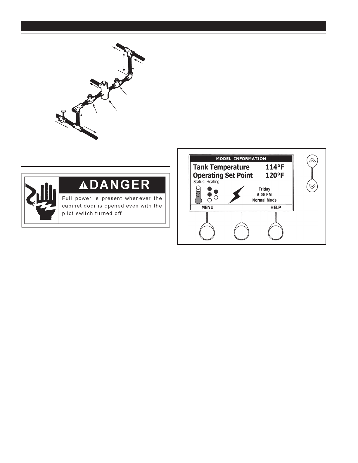
THE DESKTOP SCREEN
The illustration below shows the control system “Desktop Screen.”
This is the default screen. If there are no active Fault or Alert
conditions and no user input for approximately 10 minutes the control
system will return to this screen automatically.
ModelInformation: Model information and menu titles are shown in
the black bar at the top of the Desktop Screen.
TankTemperature: Current water temperature as sensed from the
immersion Temperature Probe.
OperatingSetPoint: Temperature at which the control system will
maintain tank (water) temperature in the Normal Mode. This line of
text will read Economy Set Point whenever the control system is
operating in the Economy Mode.
Status: The Operating State of the control system is displayed
beneath the Operating Set Point.
CONTROL SYSTEM NAVIGATION
The UIM (User Interface Module) is located on the front cabinet of the water
heater. All operational information and user settings are displayed and
accessed using the UIM. The UIM includes ve snap acting (momentary)
user input buttons; an Up, Down and 3 Operational Buttons.
Up & Down Buttons
Used to navigate (up and down) and to select (highlight) menu items.
Also used to adjust or change (increase/decrease, on/off, set time)
various user settings.
Operational Buttons
The 3 Operational Buttons are multifunctional. Their current function
is dened by the text that appears directly above each button on
the LCD screen. The function will change depending on what menu
is currently displayed or what menu item is selected. When no text
Menu: The left Operational Button is pressed to enter the Main Menu
where all control system menus are accessed. See Table 3 on page
10 for a list of control system menus.
Help: The right Operational Button is pressed to access instructions
and explanations for user settings, Operating States, Status Icons,
manufacturer’s web address, technical support phone number and
service agent contact information.
Day/Time/Operating Mode: The current time and day are also
displayed on the Desktop Screen. “Clock Not Set” will be displayed
until the time clock has been initially set. Day and Time are adjusted
in the Economy Mode Setup menu. The current Operating Mode,
either Normal Mode or Economy Mode, is displayed beneath the
day and time.
Discreet Menu Contact Information: From the Desktop Screen
press and hold down the middle (unmarked) Operational Button for
30 seconds and then release it. This will launch a discreet menu
where personalized contact information can be entered. Installing
contractors and/or service agents can enter their company name
and telephone number. This contact information will be displayed
with all Fault and Alert messages.
9
Page 10

TABLE 1 - STATUS ICONS
ICON DESCRIPTION
Water temperature in the tank has fallen. Shaded area of the animated thermometer icon will rise and fall in response to
water temperature in the storage tank as sensed from the immersion Temperature Probe.
Water temperature in the tank has reached the Operating Set Point. Shaded area of the animated thermometer icon will rise
and fall in response to water temperature in the storage tank as sensed from the immersion Temperature Probe.
The control is unable to initiate a heating cycle. This will happen whenever a Fault condition is detected by the control system
or when either of the two Enable/Disable circuits are open circuits.
The control system is in Heating Mode and has energized the electromagnetic contactor coils for at least one heating
element. This animated icon DOES NOT indicate current has been sensed from the heating elements, only that there is a
call for heat present and the control system has initiated heating element operation.
The control has detected/declared a Fault Condition. Fault message details can be viewed in the Current Fault menu.
Heating operation is discontinued (locked out) until the condition that caused the fault is corrected. Power to the water heater
must be cycled off and on to reset the control system. Note; cycling power will not reset the control system if the condition
that caused the fault has not been corrected.
The control has detected/declared an Alert Condition. The water heater will continue to operate during an Alert Condition but
there is an operational condition that requires the attention of a Qualied Service Agent. Alert message details can be viewed
in the Current Alert menu.
TABLE 2 - OPERATING STATES
STATE DESCRIPTION
Standby
Heating The control system is in the Heating Mode. At least one heating element has been energized.
Alert
Fault
The water heater is not in an active heating cycle. This usually indicates the temperature in the tank has reached the
Operating Set Point and the control system has terminated the heating cycle.
The control system has detected/declared an Alert Condition. The controls system will continue heating operation.
However, a Qualied Service Agent should be contacted to check/service the water heater.
The control system has detected/declared a Fault Condition. The control system will discontinue heating operation and
“lock out.” Power to the water heater must be cycled off and on to reset the control system. Note; cycling power will not
reset the control system until the condition that caused the fault has been corrected.
10
Page 11

TABLE 3 - CONTROL SYSTEM MENUS
MENUS DESCRIPTION
Temperatures
Heater Status
Economy Mode Setup
Alarm Output Setup
Display Settings
Heater Information
Current Fault/Alert
Most commonly accessed menu. Operating Set Point, Differential settings, Tank Temperature and Tank Probe
Offset are located in this menu.
Current Operating State/Mode (heating/standby etc) and status (open/closed - on/off - yes/no) of monitored
water heater functions and components are displayed in this menu.
Seven day 24 hour time clock with temperature set back capability to reduce operating costs during unoccupied
or reduced demand periods.
The control system’s CCB (Central Control Board - see wiring diagrams) features on board SPDT (single pole
double throw) relay contacts for building EMS (Energy Management System) notication of operational conditions
such as Fault Conditions and heating mode status. This menu features a list of user denable conditions for
relay activation.
Temperature units (°F or °C), appearance (brightness contrast) and backlight delay user adjustable settings are
located in this menu.
Elapsed time of operation, total heating cycle time, heating cycle count, heating element(s) cycle count and on
time along with UIM and CCB software revisions can be viewed in this menu.
Displays any current Alert or Fault messages.
Fault History
Fault Occurrence
Restore Factory Defaults
Help Menu
Retains 9 event history of Fault/Alert messages with time stamp. The Fault History is useful when dealing with
intermittent operational problems or when the customer has reset the control system prior to a service agent’s
arrival.
Total accumulated number each individual Fault condition has occurred is displayed in this menu. This
running total of Fault Occurrences can be useful in determining which (if any) operational problems have been
persistent.
This control system feature allows the user to restore control system user settings to their factory default settings.
Alarm Output Setup and Display Settings menu items ARE NOT changed when factory defaults are restored.
Accessible by pressing the corresponding Operational Button from most menus and screen displays. This menu
provides access to instructions and explanations for user settings, Operating States, Status Icons, manufacturer’s
web address, technical support phone number and service agent contact information.
11
Page 12

TEMPERATURES MENU
Operating Sequence
Operating Set Point
User adjustable setting 90°F to 190°F range; factory default is
120°F. When the water temperature sensed by the control system
from the immersion Temperature Probe reaches the Operating Set
Point the control system will end the heating cycle. A call for heat
will be activated again when the water temperature drops below the
Operating Set Point minus the 1st Differential Setting.
Example: Operating Set Point is 120°F, the 1st Differential Setting is
2°F (factory default). A call for heat will be activated when the sensed
water temperature drops to 118°F.
Differential Settings
On a water heater equipped with 3 heating elements, with an
Operating Set Point of 120°F and all Differential settings at 2°F the
On/Off sequencing of heating elements would be as follows:
ELEMENT
NUMBER
Element 1 2°F 118°F 120°F
Element 2 2°F 116°F 118°F
Element 3 2°F 114°F 116°F
DIFFERENTIAL
SETTING
TURN ON TEMP TURN OFF TEMP
TABLE 4.
Tank Temperature
Non adjustable information display. Current water temperature as
sensed by the control system from immersion Temperature Probe.
Tank Probe Offset
User adjustable setting -5°F to +5°F range; factory default is 0°F.
If the current Tank Temperature is sensed (from the immersion
Temperature Probe) at 120°F and the offset is adjusted to -5°F the
control system would calibrate or “offset” the Tank Temperature to
115°F. Heating cycles would then start/stop based on the calibrated
Tank Temperature.
Adjustable user setting(s) 1°F to 20° range; factory default is 2°F.
The water heaters covered in this manual will have between 1
and 5 heating elements. There is at least one Differential Setting
on all models. There will be additional Differential Settings for each
additional heating element installed.
Used to calibrate for slight differences in control system temperature
sensing. This can improve the precision of temperature control in storage
tank and at points of use. This feature can also be used to compensate
for building recirculation loops (hot water returning to storage tank) that
may cause the heating cycle to terminate prematurely.
12
Page 13

Temperature Settings
The Operating Set Point and the Differential Settings are adjusted in the Temperatures Menu. The following instructions explain how to adjust
these user settings and navigate the control system menus.
ACTION DISPLAY
From the Desktop Screen, press the Operational Button underneath
“MENU” to enter the Main Menu.
Notice how the text above the Operational Buttons on the display
changes as you navigate through the various menus and screens.
With Temperatures selected (highlight in black) in the Main Menu,
press the Operational Button underneath “SELECT” to enter the
Temperature Menu.
If Temperatures is not selected use the Up and Down buttons to select
this menu item.
With the Operating Set Point selected (highlighted in black) in the
Temperatures Menu, press the Operational Button underneath
“CHANGE” to activate the adjustment mode for this menu item.
Press the Up and Down buttons to adjust the Operating Set Point to
the desired setting.
Press the Operational Button underneath “UPDATE” to conrm the new
setting. Press the Operational Button underneath “CANCEL” to discard
the new setting and retain the previous setting.
The new Operating Set Point value should now be displayed as the
current value.
NOTE: Use this same procedure to adjust the Differential settings and
the Tank Probe Offset in the Temperatures Menu.
This same procedure is used to change user settings in other control
system menus.
13
Page 14

WATER HEATER STATUS MENU
Element # On
This menu displays non adjustable operational information. Use the
Up & Down Buttons to navigate to the bottom of this menu.
Top of Menu
Bottom of Menu
Displays the on/off status of each heating element. Yes = On, No =
Off.
Tank Full
Displays the status of the optional LWCO (Low Water Cut Off) device.
Yes = water level is acceptable, No = water level is low.
Alarm Condition
Displays the status of the user denable Alarm Output function - see
Alarm Output Setup Menu. Yes = alarm condition has been met, No
= alarm condition has not been met.
Alarm Relay Output
Displays the state of the normally open contacts of the Alarm
Output relay. This relay (J3 contacts on the CCB - see wiring
diagrams) is used for building EMS (Energy Management
System) notification of operational conditions such as Fault
conditions.
ECONOMY MODE SETUP MENU
This menu contains settings used to establish an “Economy Set
Point” and “Economy Mode” operating periods. This control system
feature can help reduce operating costs during unoccupied, low load,
or peak demand periods.
Status
Displays the current Operating State of the control system. IE:
Heating, Standby, Fault.
Elements On #
Displays the number of heating elements the control system has
energized.
ECO Contact
Displays the current state of the ECO high temperature limit switch
contacts.
Enable / Disable 1 & 2
Displays the current state, open or closed, of the two Enable/Disable
circuits (J7 socket on the CCB - see wiring diagrams on page 6)
provided for external supervisory controls such as building EMS
(Energy Management System). Both of these Enable/Disable circuits
must be closed to “enable” heating operation. If either Enable/Disable
circuit is open for any reason heating operation will be “disabled.”
There is a plug with two jumper wires installed from the factory in the
CCB J7 socket to enable heating operation when external controls
are not in use.
Desktop Screen During Economy Mode
Economy Mode Setup Menu
ServiceNote: If a supervisory control(s) is used to enable/disable
heating operation, install eld wiring between the J7 socket on
the CCB and a set of “dry contacts” on the external control per all
applicable building codes. This is a switching circuit only: DO NOT
apply any external voltage or connect any load (IE: relay coil) to
either circuit.
Setpoint Adjustment
Adjustable user setting (2°F to 50°F - factory default is
20°F) the control system uses to calculate the “Economy
Se t Poi nt .” The Economy Set Point = no rm al Op er at in g S et
Po in t minus t he p ro gr ammed Setpoin t A djustment value .
14
Page 15

The Economy Set Point is the water temperature the control
sy st em ma in ta ins d ur ing p ro grammed Economy Mode
time periods. “Economy Set Point” is displayed instead of
“Operating Set Point” and “Economy Mode” appears beneath
th e c urrent time on t he De sktop Screen du ri ng Economy
Mode time periods.
Current Time
Seven Day 24 hr clock. Use this menu item to set the current time
and day of the week. Current day and time are not set from the
factory. “Clock Not Set” will be displayed on the Desktop until the
time/day has been initially set. Note: the time will not self adjust for
Daylight Savings time.
Heater In Economy Mode
Displays whether the control system is currently operating in
Economy Mode or not.
Daily Operating Mode (Sun - Mon - Tue - Wed - Thu - Fri - Sat)
Seven daily sub menus are listed at the bottom of the Economy
Mode Setup menu. There are 3 Operating Modes in each sub menu;
“Normal Operation All Day” - “Economy Mode All Day” and “Normal
Operation Between.” Only one Operating Mode can be active, the
factory default is Normal Operation All Day.
NormalOperationAllDay: When this operating mode is active the
normal Operating Set Point is used for the entire day.
EconomyModeAll Day: When this operating mode is active the
Economy Set Point is used for the entire day.
Normal Operation Between: When this operating mode is active
there will also be start and stop times to program. The normal
Operating Set Point is used between the programmed start and stop
times and the Economy Set Point will be in effect during the rest of
the day. There is one start time and one stop time event per day.
15
Page 16

ECONOMY MODE SETTINGS
Setpoint Adjustment Value
ACTION DISPLAY
From the Desktop screen, press the Operational Button underneath
“MENU” to enter the Main Menu.
Notice how the text above the Operational Buttons on the display
changes as you navigate through the various menus and screens.
Use the Up/Down buttons to select (highlight in black) the Economy
Mode Setup menu from the Main Menu. Press the Operational Button
underneath “SELECT” to enter the Economy Mode Setup menu.
Use the Up/Down buttons to select (highlight in black) Setpoint
Adjustment. Press the Operational Button underneath “CHANGE” to
activate the adjustment mode for the Setpoint Adjustment value.
Use the Up/Down buttons to change the Setpoint Adjustment to the
desired value. The Setpoint Adjustment value is adjustable from 2°F to
50°F. The factory default is 20°F.
Notice how the text above the Operational Buttons on the display changes
to “UPDATE” & “CANCEL” when the adjustment mode is activated and
how the current value is outlined rather than highlighted in black.
Press the Operational Button underneath “UPDATE” to enter and conrm
the new value. Pressing the Operational Button underneath “CANCEL”
would discard the new value and retain the previous value.
The new Setpoint Adjustment value should now be displayed as the
current value.
16
Page 17

ECONOMY MODE SETTINGS
Time Clock Settings
ACTION DISPLAY
From the Desktop Screen navigate to the Economy Mode Setup menu.
Use the Up/Down buttons to select (highlight in black) Current Time sub
menu. Press the Operational Button underneath “CHANGE” to enter the
Current Time sub menu.
Use the Up/Down buttons to select the “Weekday” setting.
Press the Operational Button underneath “CHANGE” to activate the
adjustment mode for this setting.
Press the Up/Down buttons to adjust the Weekday setting to the current
day.
Notice how the text above the Operational Buttons on the display changes
to “ACCEPT” & “CANCEL” when the adjustment mode is activated and
how the current setting is outlined rather than highlighted in black.
Press the Operational Button underneath “ACCEPT” to enter and conrm
the new setting. Pressing the Operational Button underneath “CANCEL”
would discard the new setting and retain the previous setting.
Use the Up/Down and the CHANGE/ACCEPT Operational Buttons to
individually select and change the remaining time settings (Hour, Minutes,
AM/PM) to the current time in the same way as outlined above.
When nished making changes press the Operational Button underneath
“BACK” to conrm all new settings and update the control system. The
display will automatically return to the Economy Mode Setup menu.
The new settings should be displayed as the Current Time.
17
Page 18

ECONOMY MODE SETTINGS
Daily Operating Mode Settings
ACTION DISPLAY
Economy Mode All Day:
From the Economy Mode Setup menu use the Up/Down buttons to
select (highlight in black) the Daily sub menu for “Sun.” Press the
Operational Button underneath “CHANGE” to enter this menu.
Use the Up/Down buttons to select (highlight in black) the “Economy
Mode All Day” setting.
Press the Operational Button underneath “SELECT” to change from
the factory default Normal Operation All Day setting to the Economy
Mode All Day setting.
Press the Operational Button underneath “BACK” to conrm the
new setting and update the control system. You will be returned to
the Economy Mode Setup menu. The new setting should now be
displayed for Sun.
Normal Operation Between:
From the Economy Mode Setup menu Use the Up/Down and
CHANGE buttons to enter the Mon sub menu as described above.
Use the Up/Down buttons to select (highlight in black) the “Normal
Operation Between” setting. Press the Operational Button
underneath “SELECT” to change the operating mode for Monday to
Normal Operation Between. Note that when this setting is selected
Start and Stop time user settings appear on the display.
Use the Up/Down buttons to navigate between the Start and Stop
time Hour, Minutes and AM/PM settings.
With each item selected press the Operational Button underneath
“CHANGE” to activate the adjustment mode for each setting. Use
the Up/Down buttons to change the value to the desired setting.
Press the Operational Button underneath “ACCEPT” to enter the
new setting or “CANCEL” to discard the new setting and retain the
previous setting.
Press the Operational Button underneath “BACK” when nished to
conrm the new settings and update the control system. The display
will return to the Economy Mode Setup menu with the new settings
shown for Mon.
18
Page 19

ALARM OUTPUT SETUP MENU
Alarm Output Settings
Permits user to set the condition (from a list of options) for when
the CCB’s integral alarm output relay will be energized. Alarm relay
connections (common, normally open, normally closed) are located on
the J3 terminal strip on the CCB - see wiring diagrams. Alarm output
relay contacts are capable of switching 1 amp maximum at 120 VAC.
Changing the user settings in this menu is done using the same
methods for changing the Operating Set Point.
ServiceNote: Adjustable user settings in the Alarm Output Setup
menu are unaffected by Restore Factory Defaults.
DISPLAY SETTINGS MENU
Permits user to set display options for viewing information on the
UIM’s LCD screen.
Temperature Units
Adjustable user setting that changes temperature units display to
Celsius °C or Fahrenheit °F.
The alarm relay operates in the background according to the settings
in this menu and is not capable of disabling water heater operation.
The alarm relay is used for external notication/verication of
various operational conditions such as fault conditions and heating
mode status. This relay can be used with building EMS (Energy
Management System) and other external supervisory controls.
Output Function
Adjustable user setting. Available options for the Alarm Output
Function setting are:
HeatingMode: Used for heating mode on/off status notication.
Enable/DisableClosed: Used for notication and/or verication of
the enable/disable circuits open/closed status. There are two enable/
disable circuits available for external supervisory control(s) at the J7
socket on the CCB - see wiring diagrams on page 6. Enable/disable
circuit(s) status can be viewed in the Heater Status Menu.
Temp<HeaterSP: Used for external notication when current tank
temperature drops below Operating Set Point.
Temp<AlarmSP: Used for external notication when current tank
temperature drops below programmable Alarm SP.
Fault or Alert: Used for external notication whenever a Fault or
Alert condition is active.
Backlight Delay
Adjustable user setting that determines how long the UIM’s LCD
backlight remains illuminated after a key has been pressed. Available
settings are; Always Off, 10, 30 or 60 seconds and Always On.
Contrast
Adjustable user setting to adjust the UIM’s LCD screen contrast
between text and background.
Display Settings
Changing the user settings in this menu is done using the same
methods for changing the Operating Set Point.
ServiceNote: Adjustable user settings in the Display Settings menu
are unaffected by Restore Factory Defaults.
HEATER INFORMATION MENU
This menu displays non adjustable operational information.
Top of Menu
Fault: Used for notication whenever a Fault condition is active.
Disabled: Disables the Alarm Relay Output Function.
Alarm SP
Adjustable user setting (90°F to 190°F) the control system uses for
the “Temp < Alarm SP” function described above. This setting has no
effect with any other Alarm Output functions.
19
Page 20

Bottom of Menu
messages in chronological order in this menu. The most recent
will be at the top of the list. A time stamp is displayed below each
listed Fault and Alert message showing when the Fault or Alert
condition occurred.
The Fault History is useful when dealing with intermittent operational
problems or when the customer has reset the control system prior to
a service agent’s arrival.
With a Fault or Alert item selected press the Operational Button
underneath “VIEW” to display the details for the Fault or Alert
message. The Fault/Alert message screen displays a brief description
of the condition, contact information and access to the Advanced
service information sub menu.
Elapsed Time
Total accumulated time the control system (water heater) has been
energized.
Total Heating Time
Total accumulated time the control system has been in the heating
mode. IE: any heating elements have been energized.
Element # Cycles
Total accumulated count of heating cycles for each heating
element.
Element # On Time
Total accumulated heating on time for each heating element.
CCB Version
Software version for Central Control Board.
UIM Version
Software version for User Interface Module
CURRENT FAULT / ALERT MENU
Fault History Menu
Current/History Fault Message
This menu displays non adjustable operational information. With the
Fault History sub menu selected in Main Menu; press the Operational
Button underneath “SELECT” to display the current Fault or Alert
message. If there is not a Fault or Alert condition currently active
“(none)” is displayed to the right of this menu.
Main Menu - Current Fault Selected
FAULT HISTORY MENU
This menu displays non adjustable operational information. The
control system records and stores the last 9 Fault and Alert
FAULT OCCURRENCE MENU
Total accumulated number each individual Fault condition has
occurred is displayed in this menu. This running total of Fault
Occurrences can be useful in determining which (if any) operational
problems have been persistent.
Fault Occurrence Menu
20
Page 21

RESTORE FACTORY DEFAULTS MENU
Th is con tr ol sys te m menu all ows the use r to resto re m os t of the c on trol sys tem’s user settings to their factory default
settings. Us er s et tings in th e Alarm Ou tp ut S etup and Di sp lay Setting s me nus are una ff ec ted by exec ut ing Restore
Factory Defaults.
Restore Factory Defaults
ACTION DISPLAY
From the Main Menu use the Up/Down buttons to select (highlight in
black) the “Restore Factory Defaults” menu.
Press the Operational Button underneath “SELECT.” The Restore
Factory Defaults menu will be displayed.
From the Restore Factory Defaults menu press the Operational Button
underneath “YES.” The display will show text conrming the factory
default settings have been restored.
Press the Operational Button underneath “BACK” to exit the Restore
Factory Defaults menu.
21
Page 22

TROUBLESHOOTING CHECKLIST
Before cal lin g for service, check the followin g points to see if
the cause of trouble can be identified and corrected. Reviewing
th is checklist ma y elimi na te the need o f a s er vi ce call and
quickly restore hot water service.
BE SURE TO TURN OFF THE ELECTRICITY (ELECTRICAL
DISCONNECT SWITCH) WHEN CHECKING EQUIPMENT.
NOT ENOUGH OR NO HOT WATER
1. Be certain the electrical disconnect switch serving the water
heater is in the ON position. The pilot toggle switch on the
cabinet should be ON.
In some areas water heater electrical service may be limited
by the power company. If the heater operates on a controlled
circuit, heater recovery may be affected.
The optional manual override switches on the cabinet front may
be turned off, de-energizing the elements.
2. Check the fuses.
The electrical disconnect switch usually contains fuses.
The water heater has fuses located behind the cabinet front door.
3. If the water was excessively hot, and is now cold, the ECO
high limit switch may have activated.
• See the Temperature Regulation section of this manual
for more information on how to reset the ECO high limit
controls.
Repeated activation of the ECO high limit switch should be
investigated by a Qualified Service Agent.
4. The storage capacity and/or recovery rate of the water heater
may have been exceeded by a large demand for hot water.
Large demands require a recovery period to restore water
temperature.
5. Cold incoming water temperature will lengthen the time required
to heat water to the desired temperature.
If the heater was installed when incoming water temperature was
warm, colder water creates the effect of less hot water.
7. Se dim en t or lim e sc ale may be a ff ectin g wa ter he ate r
operation.
WATER IS TOO HOT
Refer to the TEMPERATURE REGULATION section of this
manual.
WATER HEATER MAKES STRANGE SOUNDS
1. Sediment or lime scale accumulations on the elements causes
sizzling and hissing noises when the heater is operating.
The sounds are normal, however, the tank bottom and elements
should be cleaned.
2. Some of the electrical components of the water heater make
sounds which are normal ie. contactors will “Click” or snap
as the heater starts and stops.
22
Page 23

NOTES
Page 24

500 Tennessee Waltz Parkway, Ashland City, TN 37015
Phone: 800-365-0024 • Parts: 800-433-2545 • Fax: 800-644-9306
www.statewaterheaters.com
Copyright © 2010 A.O. Smith Corporation, All rights reserved.
 Loading...