

Page 1
C O M M E R C I A L
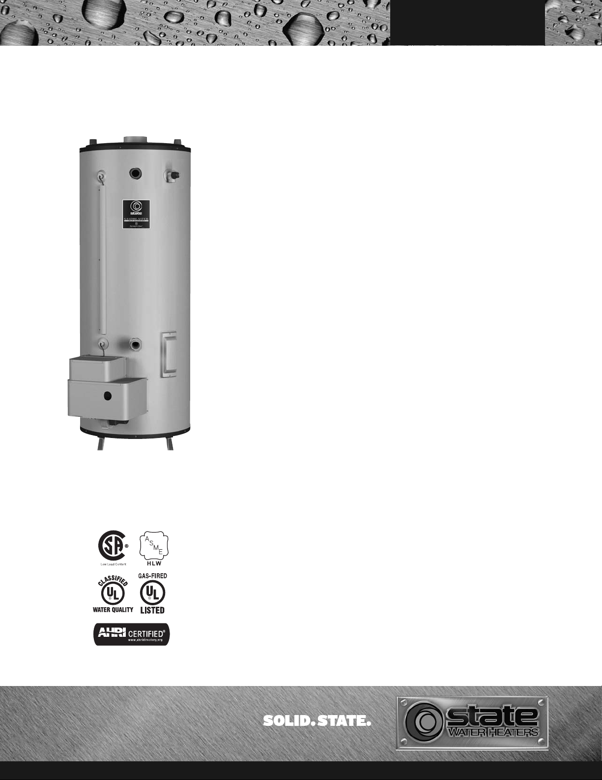
SANDBLASTER
ULTRA-LOW NOX
COMMERCIAL GAS TANK-TYPE WATER HEATERS
®
Jacket
• Heavy gauge steel finished with a baked enamel
finish over a bonderized undercoat
Easy Cleaning
• Handhole cleanout allows access for easy cleaning
Fully Tested for Safety
and Performance
• Design certified by the Underwriters Laboratory
for 180°F hot water service
• Meets rigid requirements of the National Sanitation
Foundation when equipped with optional leg kit
• Certified for use on combustible flooring
Intermittent Ignition Device
• Eliminates standing pilot
• Provides flame failure response in less than
one second
• Spark ignitor and power ON/OFF switch
Easy-to-Install
• Completely factory-assembled
• Only gas, water, vent and electric connections
need be made
• Provided with drain valve
Anodes
• Long-life, stainless steel core anode rods
Plug Kits
• Pipe nipples and caps are included to plug unused
water connections
Approval Ratings
and Certification
• All models meet ANSI Z21.10.3 - CSA 4.3
standards and the thermal efficiency and standby
loss requirements of the U.S. Department of Energy
and current edition of ASHRAE/IESNA 90.1
Other Features
• Integral automatic gas shutoff system prevents
excessive water temperature
• CSA Certified and ASME Rated T&P Relief Valve
are factory-installed
• Maximum working pressure is 160 psi standard
• Adjustable thermostat with a 120-180°F range
• All models certified up to 7,700 ft.
Three Year Limited Tank
Warranty / One Year Limited
Parts Warranty
• For complete warranty information, consult
written warranty
Image shows models
SBL81 120NE - SBL95 250NE(A)
FEATURES
82% Thermal Efficiency
Means Lower Operating Costs
Fan Assisted Combustion
• The blower is built into the Low NOx burner
assembly for Ultra-Low NOx readings that comply
with SCQAMD rule1146.2 of 14 ng/j or 20 ppm
Metal Venting
• Rated Category I Appliance. Uses standard
double wall type “B” vent
• Can be commonly vented with other
Category I appliances
• Vent connects directly to the vent connector outlet
• No Draft hood or barometric damper required
• Perfect choice for retrofit and upgrade installations
Water Connections
• For ease of installation, all SBLs feature water
connections on the top, front, and rear.
• “Hydro Cannon” inlet water connection
eliminates harmful scale buildup, extending
the life of the product
• The front inlet connection must be used for the
Hydro Cannon benefits
Glasslined Tank
• Glass is applied after the complete tank has been
assembled to give a seamless barrier against
corrosion by hot water
Installed Cost Savings
• When multiple SBL units are exclusively used
in a vent manifold, use the National Fuel Gas
Code Table 13 Vent Sizing information to
determine vent diameter than a natural draft water
heater and specifications
• The SBL often uses a smaller vent diameter than
a natural draft water heater which saves on
installation cost
Fully Automatic Digital
Control with Safety Shutoff
• Accurate, dependable control system
• Features a two speed blower control for smooth
main burner light-off
• Manual reset gas shutoff device for added safety
• Maximum inlet gas pressure is 14” W.C. Minimum
gas pressure is 3.5” W.C. Natural Gas
Foam Insulation
• Saves fuel, helps reduce standby heat loss
For more information on Ultra-Low NOx, contact:
State Water Heaters
500 Tennessee Waltz Parkway
Ashland City, TN 37015
800-365-0024 Toll-free USA
www.statewaterheaters.com
SCGSS01512
Page 2
C O M M E R C I A L
C
A
D
H
E
J
I
G
F
M
TOP OUTLET
1 1/2” NPT
TOP INLET
1 1/2” NPT
K
L
B
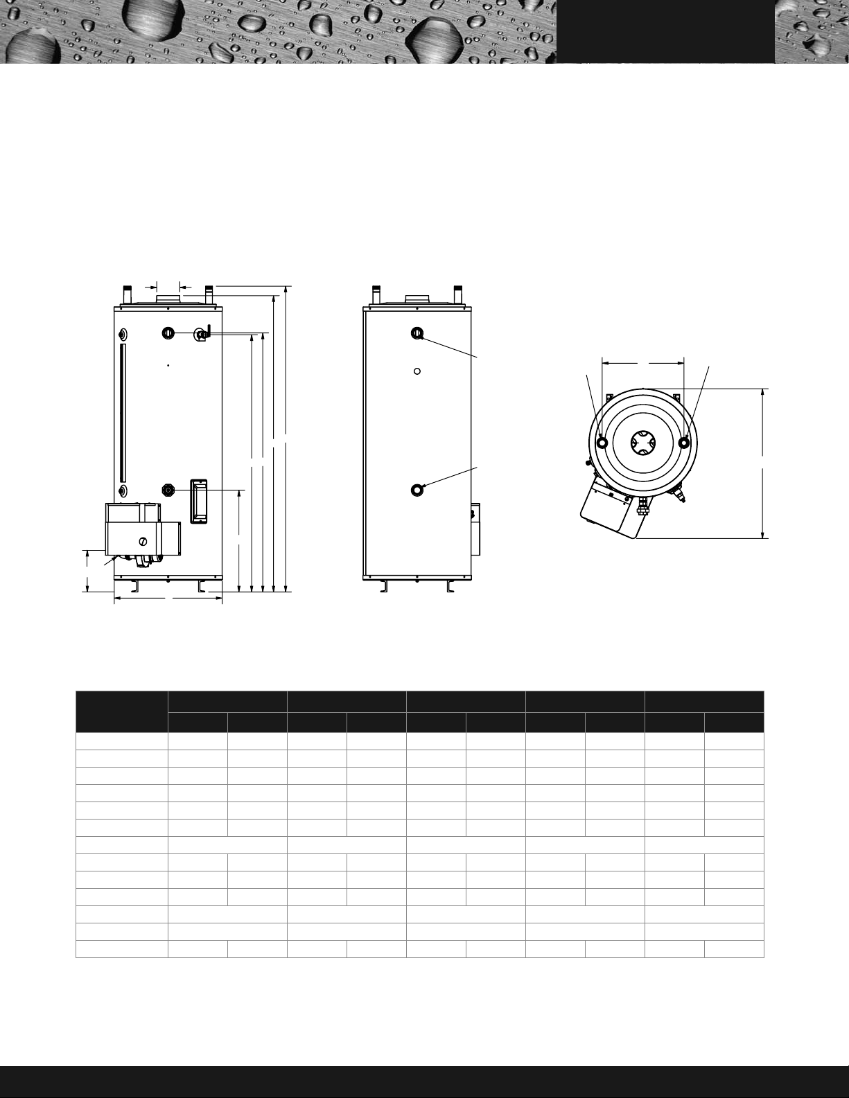
ULTRA-LOW NOX COMMERCIAL TANK-TYPE GAS
WATER HEATERS
ROUGH IN DIMENSIONS
SBL Models
FRONT VIEW
BACK V IEW
TOP VIEW
ROUGH IN DIMENSIONS
MODEL
DIMENSIONS
A 68 1/4 173.4 68 1/4 173.4 76 193.0 76 193.0 76 193.0
B 9 1/2 9 1/2 9 1/2 9 1/2 9 1/2 9 1/2 9 1/2 9 1/2 9 1/2 9 1/2
C 70 1/2 179.1 70 1/2 179.1 78 1/4 198.8 78 1/4 198.8 78 1/4 198.8
D 58 1/4 147.8 58 1/4 147.8 65 3/4 167.0 65 3/4 167.0 65 3/4 167.0
E 26 1/4 66.5 26 1/4 66.5 25 3/4 65.4 25 3/4 65.4 25 3/4 65.4
F 21 53.3 21 53.3 21 53.3 21 53.3 21 53.3
G 1/2 NPT 1/2 NPT 1/2 NPT 1/2 NPT 1/2 NPT
H 58 1/2 148.8 58 1/2 148.8 66 1/4 168.3 66 1/4 168.3 66 1/4 168.3
I 6 15.2 6 15.2 6 15.2 6 15.2 6 15.2
J 27 3/4 70.5 27 3/4 70.5 27 3/4 70.2 27 3/4 70.2 27 3/4 70.2
K 1 1/2 NPT 1 1/2 NPT 1 1/2 NPT 1 1/2 NPT 1 1/2 NPT
L 1 1/2 NPT 1 1/2 NPT 1 1/2 NPT 1 1/2 NPT 1 1/2 NPT
M 38 1/2 97.8 38 1/2 97.8 38 1/2 97.8 38 1/2 97.8 38 1/2 97.8
“A” after model number designates ASME construction
Dimensions and specifications subject to change without notice in accordance with our policy of continuous product improvement.
All models rated at 82% thermal efficiency
Models avaiable for sale in California only
SBL81 120NE SBL81 154NE SBL95 180NE SBL95 199NE SBL95 250NE(A)
INCHES CM INCHES CM INCHES CM INCHES CM INCHES CM
SCGSS01512 Page 2 of 4
Page 3

C O M M E R C I A L
K
L
J
B
G
E
D
H
A
C
1 1/2"
NPT
I
F
M
TOP OUTLET
1 1/2" NPT
TOP INLET
1 1/2" NPT
ULTRA-LOW NOX COMMERCIAL TANK-TYPE GAS
WATER HEATERS
ROUGH IN DIMENSIONS
SBL Models
FRONT VIEW
BACK V IEW
TOP VIEW
ROUGH IN DIMENSIONS
MODEL
DIMENSIONS
A 76 193 76 193 76 193 76 193
B 16 1/4 41.2 16 1/4 41.2 16 1/4 41.2 16 1/4 41.2
C 78 1/4 198.8 78 1/4 198.8 78 1/4 198.8 78 1/4 198.8
D 65 3/4 167 65 3/4 167 65 3/4 167 65 3/4 167
E 25 3/4 65.4 25 3/4 65.4 25 3/4 65.4 25 3/4 65.4
F 21 53.3 21 53.3 21 53.3 21 53.3
G 3/4 NPT 3/4 NPT 3/4 NPT 3/4 NPT
H 66 1/4 168.3 66 1/4 168.3 66 1/4 168.3 66 1/4 168.3
I 6 15.2 6 15.2 6 15.2 6 15.2
J 27 3/4 70.5 27 3/4 70.5 27 3/4 70.5 27 3/4 70.5
K 1 1/2 NPT 1 1/2 NPT 1 1/2 NPT 1 1/2 NPT
L 1 1/2 NPT 1 1/2 NPT 1 1/2 NPT 1 1/2 NPT
“A” after model number designates ASME construction
Dimensions and specifications subject to change without notice in accordance with our policy of continuous product improvement.
All models rated at 82% thermal efficiency
Models avaiable for sale in California only
SCGSS01512 Page 3 of 4
M 41 104 41 104 41 104 41 104
SBL85 275NE(A) SBL85 310NE(A) SBL85 366NE(A) SBL85 390NE(A)
INCHES CM INCHES CM INCHES CM INCHES CM
Page 4

RECOVERY CAPACITIES, BASED ON 82% EFFICIENCY
U. S. GALLONS / HR. AND LITERS / HR. AT TEMPERATURE RISE INDICATED
DEG. F 36 40 50 54 60 70 72 80 90 100 108 110 120 126 130 140
DEG. C 20 22 28 30 33 39 40 44 50 56 60 61 67 70 72 78
SBL81 120NE
SBL81 154NE
SBL95 180NE
SBL95 199NE
SBL95 250NE(A)
INPUT
INPUTkWU.S.
KBTUH
120,000 81 82 GPH 331 298 239 221 199 170 166 149 133 119 110 108 99 95 92 85
154,000 81 82 GPH 425 383 306 283 255 219 213 191 170 153 142 139 128 121 118 109
180,000 93 82 GPH 497 447 358 331 298 256 248 224 199 179 166 163 149 142 138 128
199,000 93 82 GPH 549 494 396 366 330 283 275 247 220 198 183 180 165 157 152 141
250,000 93 82 GPH 690 621 497 460 414 355 345 311 276 248 230 226 207 197 191 177
GAL. LITERS
35 307 LPH 1254 1129 903 836 752 645 627 564 502 451 418 410 376 358 347 322
45 307 LPH 1609 1448 1159 1073 966 828 805 724 644 579 536 527 483 460 446 414
53 352 LPH 1881 1693 1354 1254 1129 967 941 846 752 677 627 616 564 537 521 484
58 352 LPH 2080 1872 1497 1386 1248 1070 1040 936 832 749 693 681 624 594 576 535
73 352 LPH 2613 2351 1881 1742 1568 1344 1306 1176 1045 941 871 855 784 746 723 672
EFF.
%
C O M M E R C I A L
U. S. GALLONS / HR. AND LITERS / HR. AT TEMPERATURE RISE INDICATED
DEG. F 36 40 50 54 60 70 72 80 90 100 108 110 120 126 130 140
DEG. C 20 22 28 30 33 39 40 44 50 56 60 61 67 70 72 78
SBL85 275NE(A)
SBL85 310NE(A)
SBL85 366NE(A)
SBL85 390NE(A)
INPUT
INPUTkWU.S.
KBTUH
275,000 85 82 GPH 754 678 543 502 452 388 377 339 301 271 251 247 226 215 209 194
310,000 85 82 GPH 849 765 612 566 510 437 425 382 340 306 283 278 255 243 235 218
366,000 85 82 GPH 1003 903 722 669 602 516 501 451 401 361 334 328 301 287 278 258
390,000 85 82 GPH 1069 962 769 712 641 550 534 481 427 385 356 350 321 305 296 275
GAL.
81 322 LPH 2853 2567 2054 1902 1712 1467 1426 1284 1141 1027 951 934 856 815 790 734
91 322 LPH 3216 2894 2315 2144 1929 1654 1608 1447 1286 1158 1072 1052 965 919 890 827
107 322 LPH 3797 3417 2734 2531 2278 1953 1898 1708 1519 1367 1266 1243 1139 1085 1051 976
114 322 LPH 4046 3641 2913 2697 2427 2081 2023 1820 1618 1456 1349 1324 1214 1156 1120 1040
LITERS
EFF.
%
GAS AND ELECTRICAL CHARACTERISTICS
MODEL GAS TYPE
MINIMUM MAXIMUM
All Models Natural 3.5” W.C. (0.87 kPa) 14” W.C. (3.48 kPa) 120 / 60 < 5
MODEL
SIDES & REAR TOP COVER SIDES & REAR TOP COVER
ALL MODELS
Approx. Shipping Weight STD
Approx. Shipping Weight ASME
CLEARANCE TO
COMBUSTIBLES
0” 12” 0” 12”
SBL81 120NE SBL81 154NE SBL95 180NE SBL95 199NE SBL95 250NE(A) SBL85 275NE(A) SBL85 310NE(A) SBL85 366NE(A) SBL85 390NE(A)
lbs. kg. lbs. kg. lbs. kg. lbs. kg. lbs. kg. lbs. kg. lbs. kg. lbs. kg. lbs. kg.
750 340 750 340 835 379 835 379 835 379 850 386 850 386 850 386 850 386
– – – – – – – – 880 399 900 408 900 408 900 408 900 408
CLEARANCE TO
NON-COMBUSTIBLES
GAS SUPPLY PRESSURE
ALL MODELS
MODEL
VOLTS / HZ AMPERES
WATER CONNECTIONS IN INCHES
INLET OUTLET
Top Front Back Top Front Back
1-1/2 1-1/2 1-1/2 1-1/2 1-1/2 1-1/2
NSF LEG KIT
• Meets NSF Standard 5 with optional leg kit - Part # 9008214005
SAMPLE SPECIFICATION
Water Heater(s) shall be Model __________ as manufactured by STATE, or equal. Water heater(s) shall be of glasslined design, and gasfired, equipped to burn natural gas and design
certified by the Underwriter Laboratory under Volume III tests for commercial heaters for delivery of 180°F water, and meet or exceed the thermal efficiency and standby loss
requirements of the U.S. Department of Energy and Current Edition of ASHRAE/IESNA 90.1. Heaters shall have an input rating of __________ and a recovery rating of __________
GPH at a temperature rise of 100°F with a storage capacity of __________ gallons. Heaters shall be equipped with 1 1/2” water inlet and outlet openings, a 2 3/4” x 3 3/4” boilertype handhole cleanout and shall have a maximum working pressure of 160 psi. Water heater(s) shall be equipped with an integrated control system consisting of a 180°F adjustable
thermostat with upper and lower sensing bulbs, which average the water temperatures at the top and bottom of the tank for maximum water temperature control. Heater(s) shall be
provided with a manual reset gas shutoff device, anodes for cathodic protection and IID system. CSA Certified and ASME Rated T&P Relief Valve shall be furnished and installed
by the factory. The heater shall be insulated with foam insulation or equal. The outer jacket shall have a baked enamel finish over a bonderized undercoating. All internal surfaces of
the heater(s) exposed to water shall be glass-lined with an alkaline borosilicate composition that has been fused-to-steel by firing at a temperature range of 1400° to 1600°F. Heater
tank shall have a 3 year limited warranty against corrosion or sediment buildup as outlined in the written warranty. Fully illustrated instruction manual to be included.
For complete information on limited warranties, consult written warranty or contact
the State Customer Care Center at 1-800-365-0024.
State Industries, Inc., reserves the right to make product changes or improvements without prior notice.
For more information on Ultra-Low NOx, contact:
State Water Heaters
500 Tennessee Waltz Parkway
Ashland City, TN 37015
800-365-0024 Toll-free USA
www.statewaterheaters.com
SCGSS01512 Page 4 of 4 © 2012 State Industries, Inc. Printed in U.S.A
 Loading...