

Page 1
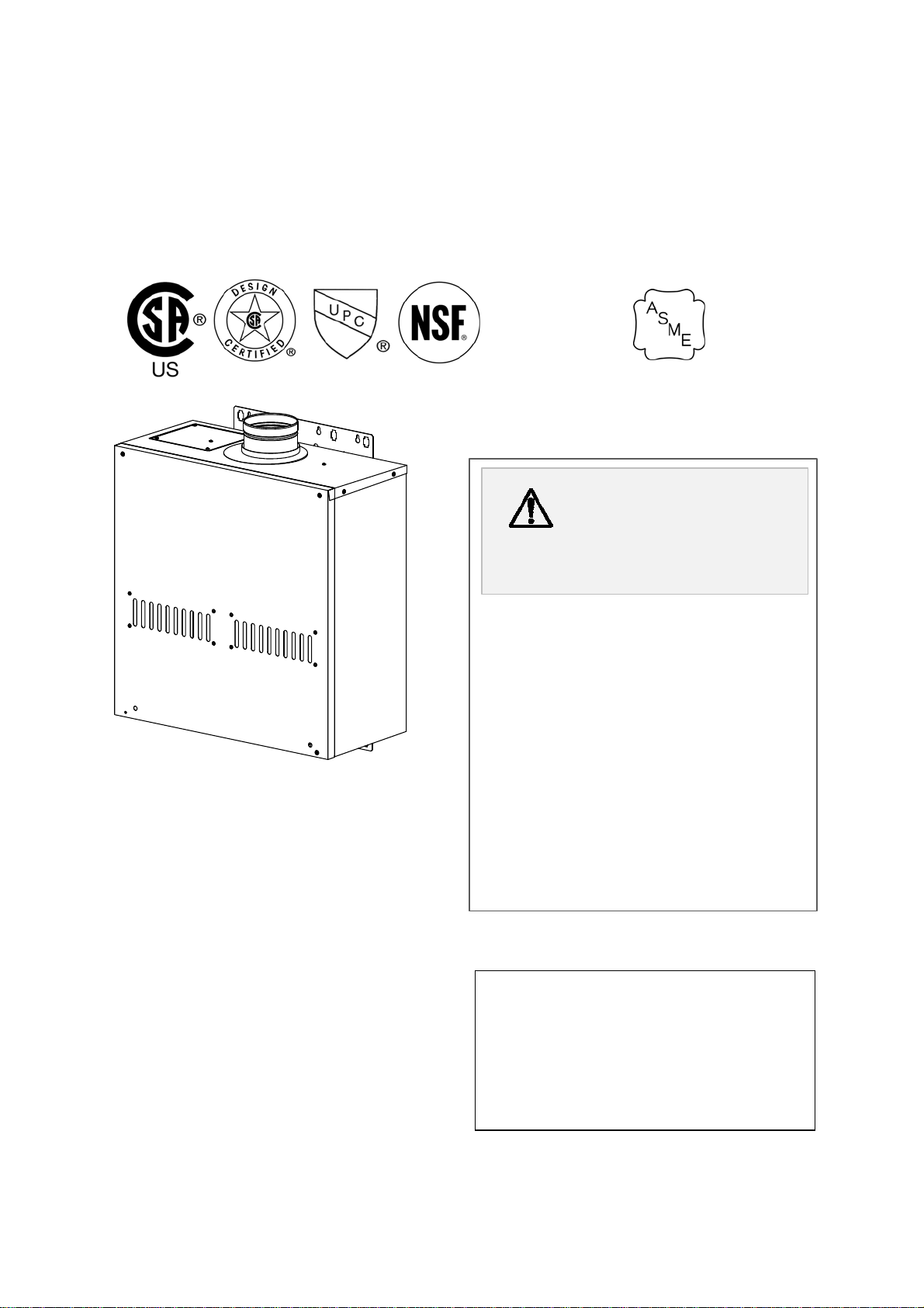
910 / 910 ASME (T-M50/T-M50 ASME)
On-Demand Water Heater
Installation Manual and Owner’s Guide
Gas Tankless Water Heater
910 / 910 ASME
(T-M50 / T-M50 ASME) Models
Suitableforpotablewaterheatingandspace‐heat ing
*Pleaserefertolocalcodesforspace‐heatingcompliance.
ANSI Z21.10.3
andCSA4.3
HLW
WARNING
-Do not store or use gasoline or other
flammable vapors and liquids in the vicinity
of this or any other appliance.
-WHAT TO DO IF YOU SMELL GAS
Do not try to light any appliance.
Do not touch any electric switch, do not
use any phone in your building.
Immediately call your gas supplier from
a neighbor's phone. Follow the gas
supplier's instructions.
If you cannot reach your gas supplier,
call the fire department.
-Installation and service must be performed
by a qualified installer, service agency or
*
the gas supplier.
If the information in these
instructions is not followed
exactly, a fire or explosion
may result causing property
damage, personal injury or
death.
For supplying potable
hot water
ASME model ONLY
FEATURING
ENDLESS HOT WATER
ON-DEMAND USAGE
COMPACT, SPACE SAVING
ENERGY CONSERVATION
COMPUTERIZED SAFETY
NO PILOT LIGHT
EASY-LINK SYSTEM
If you have any questions, please
call or write to:
500 Tennessee Waltz Parkway
Ashland City, TN 37015
Toll Free: 1-877-737-2840
Page 2
CONTENTS
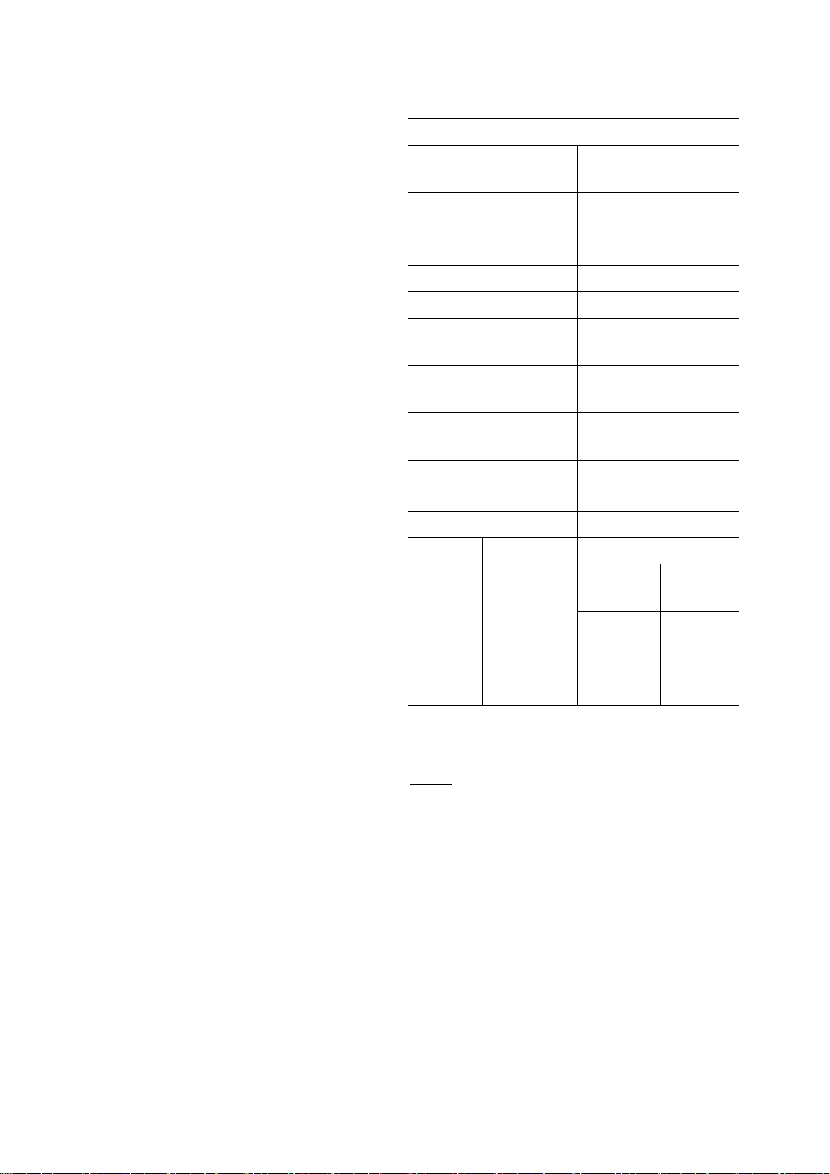
SPECIFICATIONS
SPECIFICATIONS……………………….
INTRODUCTION…………………………
SAFETY GUIDELINES………………....
INSTALLATION…………………………..
General…………………………………
Included Accessories…….……………
Warning for Installations………………
Outdoor Installation……………………
Indoor Installation…………………......
Direct Intake Vent System…………….
Venting Instructions………………......
Gas Supply / Gas Pipe Sizing………..
Water Connections……………………
Pressure Relief Valve…………………
Electrical Connections……………......
Remote Controller Connection………
Pump Control Connections......……...
Pump Control Mode……………………
Easy-Link System………………………
Multi-Unit System………………………
Initial Operation………… ……………..
NORMAL OPERATION………………….
Normal Operation…………………......
Flow……………………………………..
Freeze Protection System…………...
Temperature Setting s………………….
Maintenance and Service…………….
GENERAL TROUBLESHOOTING…… . .
OPERATING SAFETY………………...…
APPLICATIONS………………………......
Re-Circulation……………...................
Dual-Purpose Heating………………...
ADDITIONAL CLEARANCES……………
OPTIONAL ITEMS………...……………..
COMPONENTS DIAGRAM…………….
PARTS LIST………………………………
OUTPUT TEMPERATURE CHART……
LIMITED WARRANTY……………….......
The manufacturer reserves the right to discontinue, or change at any time,
specifications or designs without notice and without incurring obligations.
Natural Gas Input
2
(Operating Range)
3
5
Propane Input
6
(Operating Range)
7
Gas Connection 1” NPT
7
Water Connections
8
Water Pressure
9
10
Natural Gas
11
Inlet Pressure
12
Propane
16
Inlet Pressure
19
Manifold Pressure**
19
20
Weight
21
Dimensions
22
23
Ignition
24
27
29
30
Electric
30
32
32
33
34
*40 psi or above is recommended for maximum flow.
**The Manifold Pressure is the factory setting and
35
38
40
40
41
42
43
44
48
51
51
generally should not need adjustment.
NOTE
*All references to the 910 (T-M50) also refer to the
910 ASME (T-M50 ASME) model
*Check the rating plate to ensure this product
matches your specifications.
*In accordance with ANSI Z21.10.3,
CO emission does not exceed 400 PPM for
normal input.
Supply
Consumption
Min: 15,000 Btu/h
Max: 380,000 Btu/h
Min: 15,000 Btu/h
Max: 380,000 Btu/h
1” NPT
15 - 150 psi *
Min. 5.0” WC
Max. 10.5” WC
Min. 8.0” WC
Max. 14.0” WC
Natural: 2.8” WC
Propane: 3.8” WC
102 lbs.
H25.3”×W24.8”×D11.8”
Electric Ignition
120 VAC / 60 Hz
Operation
Standby
FreezeProtection
178 W
(1.48A)
16 W
(0.13A)
271 W
(2.26A)
- 2 -
Page 3
INTRODUCTION
p
your
This manual provides information necessary for the installation, operation, and
maintenance of the water heater.
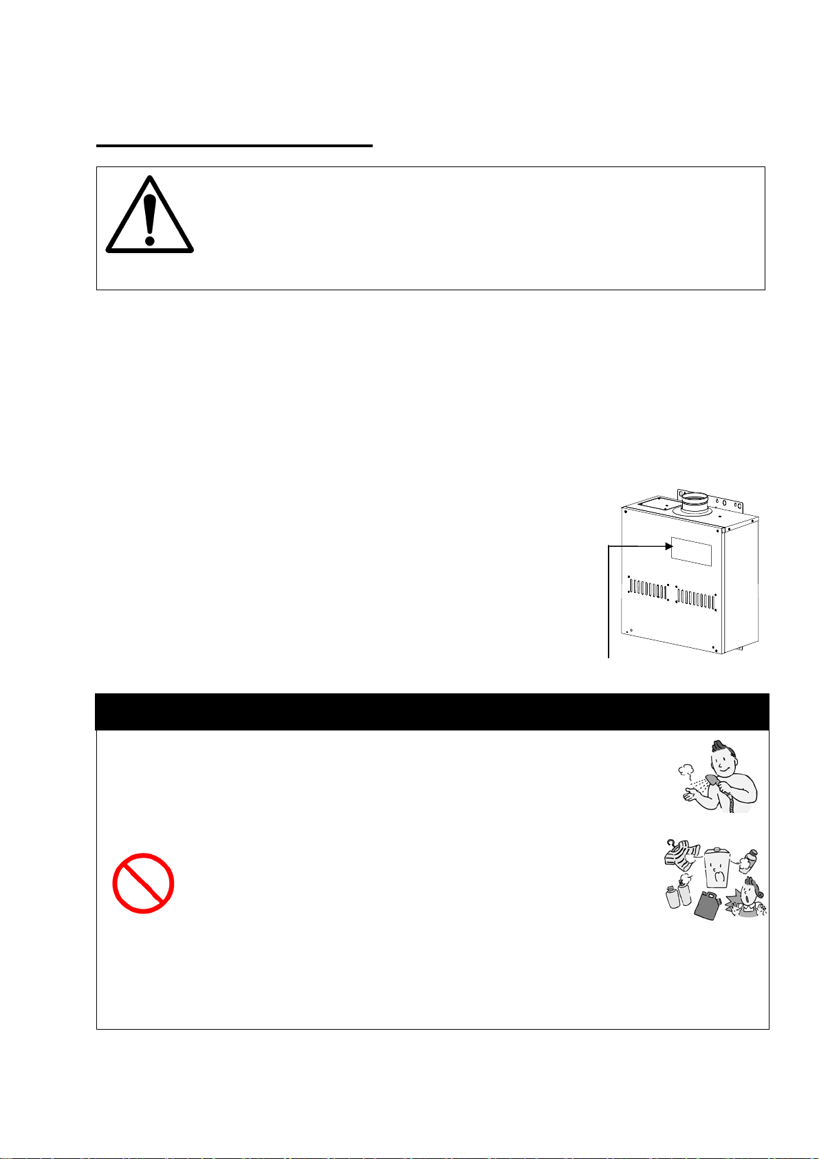
The model description is listed on the rating plate which is a ttached to the front cover of
the water heater.
Please read all installation instructions completely before installing this product.
If you have any problems or questions regarding this equipment, consult with the
manufacturer or its local re
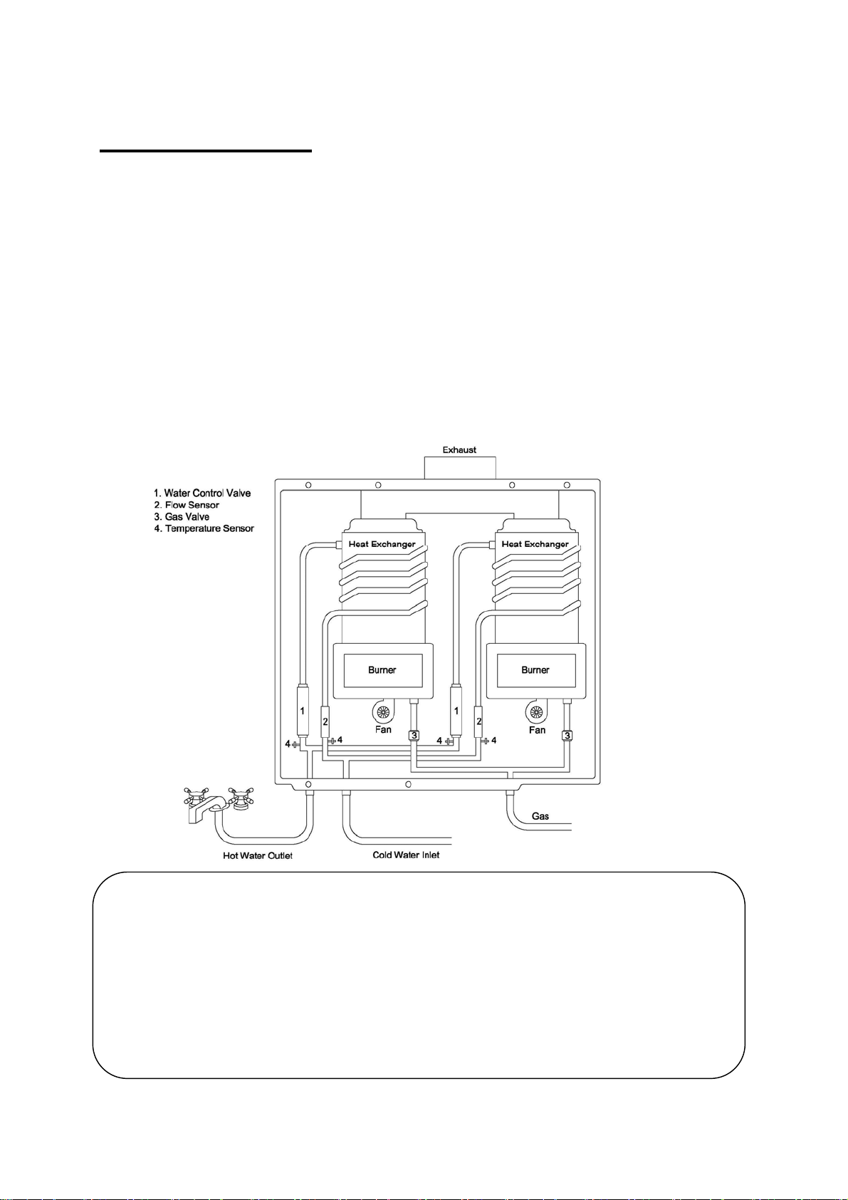
This equipment is an on-demand, tankless water heater designed to efficiently supply
endless hot water for
The water heater has two h eat exchangers. The primary and secondary heat exch angers
alternate roles, extending the life of the water heater (see p. 4).
The principle behind the water heater is simple:
1. A hot water tap is turned on.
2. Water enters the heater.
3. The water flow sensor detects the water flow.
4. The computer automatically ignites the burner.
5. Water circulates through the heat exchanger and then gets hot.
6. The computer will modulate the gas supply valve and water flow to produce the right
amount of hot water at the correct temperature.
7. When the tap is turned off, the unit shuts down.
resentative.
needs.
*This diagram illustrates
tankless water heater
design concepts only and is
not accurate to the water
heater’s physical
- 3 -
Page 4
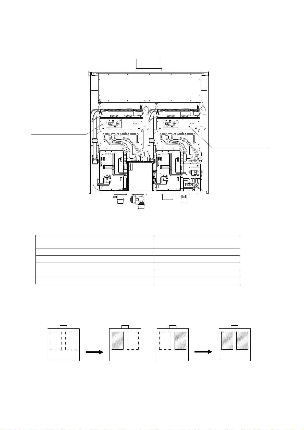
TWO COMBUSTION SECTIONS WITHIN THE 910 (T-M50)
o
(p
y)
Left combustion section
Right combustion section
The water heater contains two combustion sections. The section that turns on first is whichever
section the water heater decides is the primary section. The moment at which the secondary
section fires will depend on the total flow rate and set temperature of the water heater:
Flow rate at which the secondary section fires
( GPM )
3.2 100-120
2.9 125,130
2.6 140
2.4 145,150
2.1 155-185
Example: If the set temperature is 120ºF:
*The section(s) in operation is indicated by the black square(s).
Total Flow < 0.5 GPM
(no section turns on)
910 (T-M50) 910 (T-M50) 910 (T-M50) 910 (T-M50)
0.5 GPM ≦ Total Flow < 3.2
GPM
rimary section fires onl
Set temperature of the 910 (T-M5 0 )
(°F)
3.2 GPM < Total Flow
(both primary and
secondary sections fire)
r
Depending on which side is the primary section
*The primary and secondary section will reverse roles every 100 firing cycles or every 12 hours of unit operation.
- 4 -
Page 5
SAFETY GUIDELINES
Installation and service must be performed by a qualified installer (for
example, a licensed plumber or gas fitter), otherwise the warranty by the
manufacturer will be void.
The installer (licensed professional) is responsible for the correct
WARNING
PLEASE READ THIS MANUAL CAREFULLY AND FOLLOW ALL DIRECTIONS.
installation of the water heater and for compliance with all national,
state/provincial, and local codes.
GENERAL
1. Follow all local codes, or in the absence of loca l codes, follow the most recent edition of
the National Fuel Gas Code: ANSI Z223.1/NFPA 54 in the USA or CAN/CSA B149.1
Natural Gas, Propane Installation Code in Canada.
2. Properly ground the unit in accordance with all local code s or in the absence of local codes,
with the National Electrical Codes: ANSI/NFPA 70 in the USA or CSA standard C22.1
Canada Electrical Code Part 1 in Canada.
3. Carefully plan where you intend to install the water heater. Please ensure:
Your water heater will have enough combustible air and
proper ventilation.
Locate your heater where water leakage will not damage
surrounding areas (please refer to p. 6).
4. Check the rating plate for the correct GAS TYPE, GAS
PRESSURE, WATER PRESSURE and ELECTRIC RATING.
*If this unit does not match your requirements, do not install and
consult with the manufacturer.
5. If any problem should occur, turn off all hot water taps and turn off
the gas. Then call a trained technician or the Gas Company or the
manufacturer.
Rating plate
WARNING
Water temperatures over 125ºF (52ºC) can cause severe burns instantly or death from
scalding. The water temperature is set at 120ºF (49ºC) from the factory to minimize any
scalding risk. Before bathing or showering always check the water temperature.
Do not store or use gasoline or other flammables, vapors, or liquids in the
vicinity of this appliance.
Do not reverse the water and/or gas connections as this will da mage
the gas valves and can cause severe injury or death. Follow the
diagram on p. 18 when installing your water heater:
Do not use this appliance if any part has been in contact with or been
Prohibited
immersed in water. Immediately call a licensed plumber, a licensed gas
fitter, or a professional service technician to inspect and/or service the
unit if necessary.
Do not disconnect the electrical supply if the ambient temperature will drop below
freezing. The Freeze Prevention System only works if t he unit has electrical power. The
warranty will not be covered if the heat exchanger is damaged due to freezing. Refer to
the section on the Freeze Prevention System on p. 32 for more information.
- 5 -
Page 6
INSTALLATION
All gas water heaters require careful and correct installation to ensure safe and efficient
operation. This manual must be followed exac tly. Read the “Safety Guidelines” section at the
beginning of this manual.
The warranty will not cover damage caused by water quality. Water
hardness that leads to scale formation and/or corrosion may
affect/damage the water heater. Hard water scaling and/or corros ion must
be avoided or controlled by proper water treatment.
CAUTION
WARNING
The manufacturer recommends using the direct-vent kit, when the
water heater is installed in a beauty salon. Some chemicals used in a
beauty salon may affect the flame sensor. Water heater may not work
properly.
Although this water heater is designed to operate with minimal sound , the
manufacturer does not recommend installing the unit on a wall
adjacent to a bedroom, or a room that is intended for quiet study or
meditation, etc.
Locate your heater close to a drain where water leakage will not do dama ge
to surrounding areas. As with any water hea ting applianc e, the potentia l for
leakage at some time in the life of the product does exist. The manufacturer
will not be responsible for any water damage that may occur. If you install a
drain pan under the unit, ensure that it will not restrict the combustion air
flow.
The water heater weighs 102 lbs. Ensure that any and all support
structures (whether it is installed on a wall, on a support stand, etc.)
have enough strength to support and hold the water heater.
When handling the water heater, do not place your hands inside the
flue collar. Injury may result.
The manufacturer does not recommend installing unit in an attic due
to safety issues. If you install your water heater in an attic:
Make sure your unit will have enough combustion air and proper
ventilation.
Keep the area around your water heater clean. When dust collects on
the flame sensor, the water heater will shut down on errors.
If the above conditions cannot be met, use the direct-vent conversion kit
9007669005 (TM-DV50).
Locate unit for easy access for service and maintenance.
A drain pan is required to be installed under the water heater in cas e of
leaks.
- 6 -
Page 7
GENERAL
1. The manifold gas pressure is preset at the factory. It is computer controlled and should
not need adjustment.
2. Maintain proper space for servicing. Install the unit so that it can be connected or
removed easily. Refer to p. 9 and p. 10 for proper clearances.
3. The electrical connection requires a means of disconnection, to terminate power to the
water heater for servicing and safety purposes.
4. If you will be installing the unit in a contaminated area with a high level of dust, sand,
flour, aerosols or other contaminants/chemicals, they can become airborne and enter
and build up within the fan and burner causing damage to the unit. In those
environments (e.g. residential or commercial laundry facilities, hair salons, pet salons,
chemical plants etc.), please purchase the optional direct-vent conversion kit and
convert the water heater to a s ealed combustion unit. Direct venting allows the water
heater to draw fresh intake air from the ou tside. The warranty will not cover damage
caused to the unit due to installation in a contaminated environment that has not been
converted using the direct-vent conversion kit.
5. Particles from flour, aerosols, and other contaminants may clog the air vent or reduce
the functions of the rotating fan and cause improper burning of the gas. Regularly ensure
that the area around the unit is dust- or debris-free; regular maintenance is
recommended for these types of environment.
6. Do not install the unit where the exhaust vent is pointing into any opening in a building or
where the noise may disturb your neighbors . Make sure the vent termination mee ts the
required distance by local code from any doorway or opening to prevent exhaust from
entering a building (refer to p. 15).
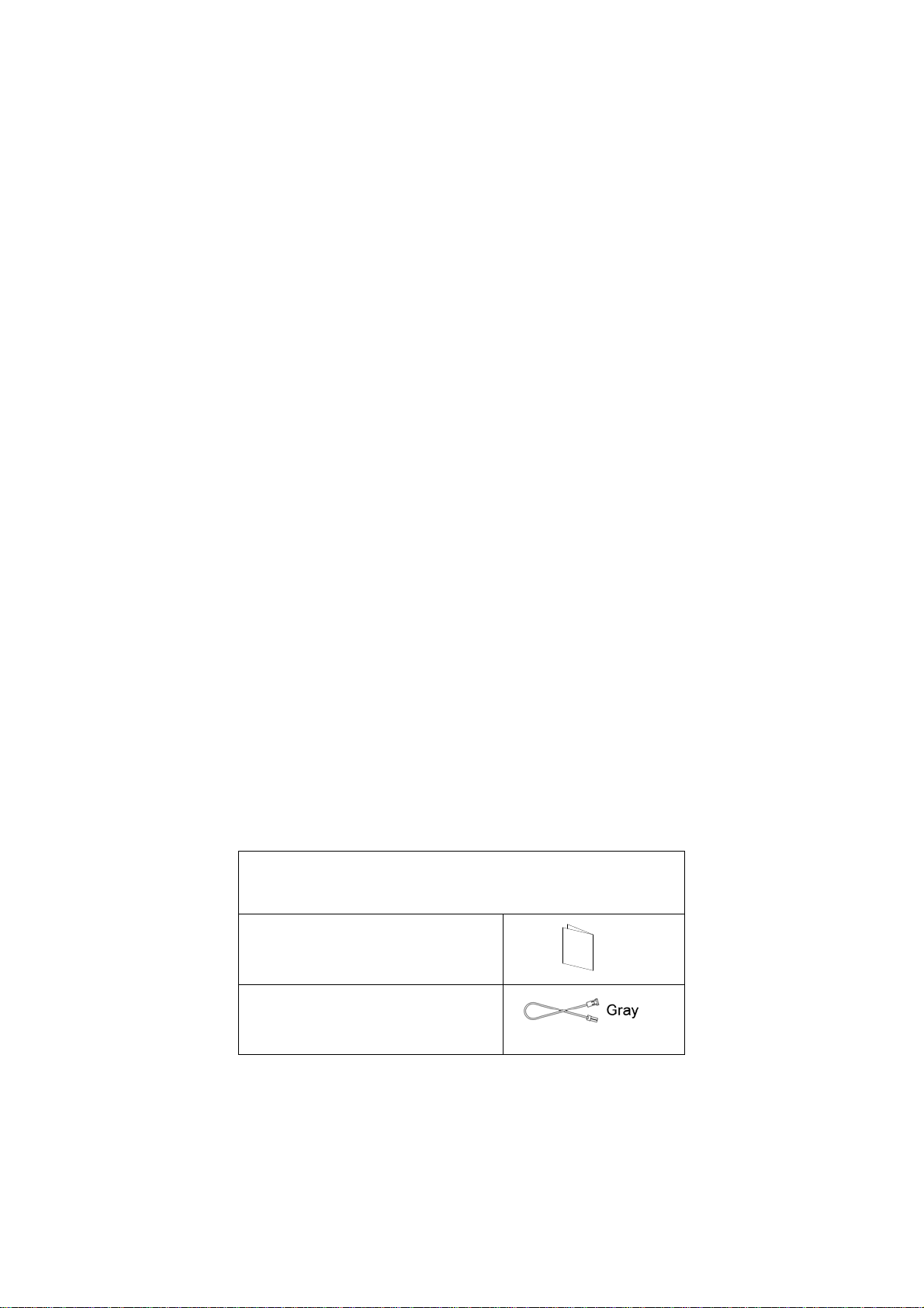
INCLUDED ACCESSORIES
Check that these items below are included with the water heater.
Items
Manual
Communication Cable
- 7 -
Qty: 1
Qty: 1
Page 8
WARNING FOR INSTALLATIONS
FOR YOUR SAFETY, READ BEFORE INSTALLATION:
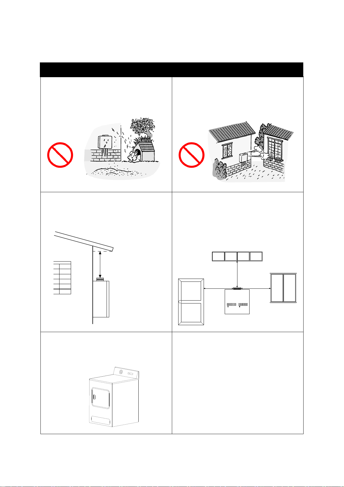
Do not install the heater where water, debris
or flammable vapors may get into the flue
terminal. This may cause damage to the
heater and void the warranty.
Do not have the vent terminal pointing toward
any opening into a building. Do not locate
your heater in a pit or location where gas a nd
water can accumulate.
Prohibited Prohibited
Do not install this water heater under an
overhang less than 3 feet from its top or
eaves. The area under an overhang must be
open to three sides.
Do not install the water heater vent terminator
within 1 ft. in the USA of any air intake or
building opening, and within 3 ft. in Canada of
any air intake or building opening. (Refer to
p.15)
3 Ft.
Do not install next to a dryer or any source of
airborne debris that can be trapped inside the
combustion chamber, unless the system is
direct vented.
1 Ft.(USA )
3 Ft.(Canada )
1 Ft.(USA )
3 Ft.(Canada )
Takagi
1 Ft.(USA )
3 Ft.(Canada )
- 8 -
Page 9
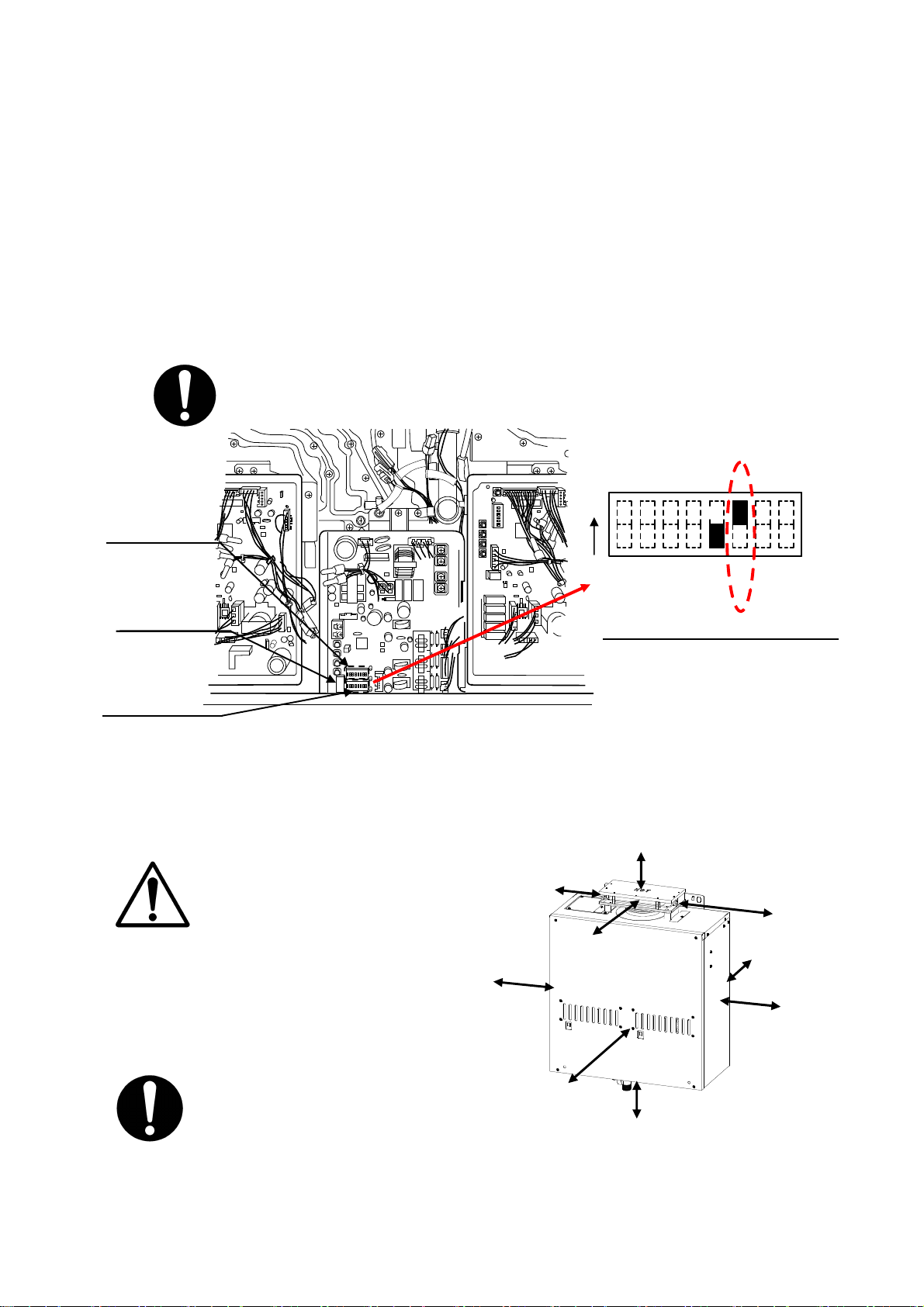
OUTDOOR INSTALLATION
1. Follow all local codes, or in the absence of local codes, follow the most recent edition of
the National Fuel Gas Code: ANSI Z223.1/NFPA 54 in the USA or CAN/CSA B149.1
Natural Gas, Propane Installation Code in Canada.
2. Install outdoors only in areas with mild, temperate climates.
3. Ensure that the unit is set for outdoor installation. Locate the central computer board.
On the central computer board, locate the lower bank o f dipswitches to the right of the
7-Seg. LED on the computer board. The ‘OUT’ dipswitch on that bank should be
switched to its ‘ON’ (up) position (Do not adjust the upper bank of dipswitches).
Upper bank of
dipswitches
7-Seg LED
Lower bank of
dipswitches
4. The outdoor vent cap must be used when unit is installed outdoor. The manufacturer
requires the use of its part No. 9007677005 (TM-VC50).
Make sure power to the unit is
turned OFF before changing
the dipswitch settings.
The dark square is the direction
the dipswitch should be set to.
1 2 3 4 5 6 7 8
O
N
TMP1
TMP2
TMP3
MODE
DIRE
OUT
Lower Bank of Dipswitches
P-ALARM
MST
5. When installed outdoors, the water heater shall be wall-mounted or mounted on a stand.
Locate the water heater in an open, unroo fed area and maintain the followin g minimum
clearances:
There is a 2” clearance from the
left and right sides of the unit to
combustible and non-combustible
*Side 24”
Top 36”
*Side 24”
surfaces. Howeve r, if any porti on
or area of the surface is exposed to
the exhaust fumes (i.e. directly to
the sides of the vent cap), that
surface must be at least 24”
away.
Keep the clearances.
Side 2”
Front 4”
(24” Recommended
for Maintenance)
*Front 24”
Bottom 12”
Back 0.5”
Side 2”
- 9 -
Page 10
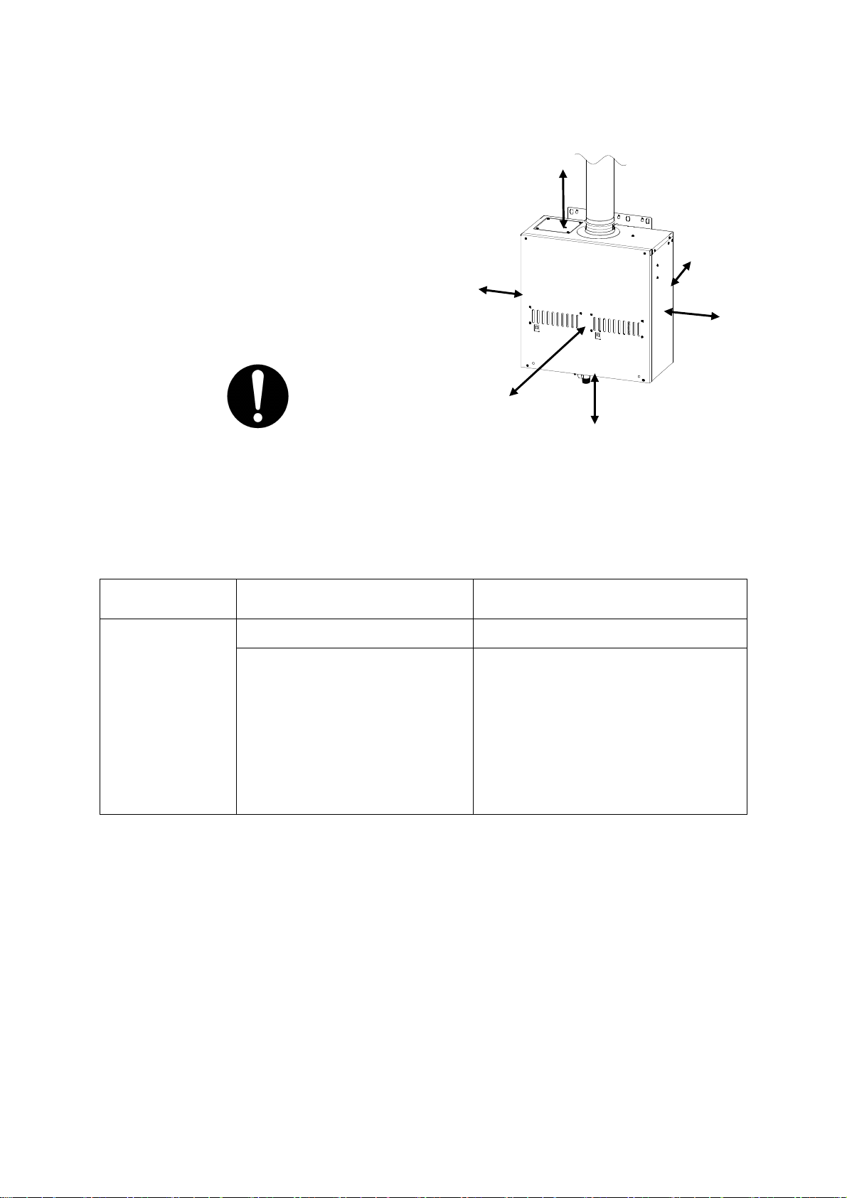
INDOOR INSTALLATION
1. Follow all local codes, or in the absence o f
local codes, follow the most recent edition
of the National Fuel Gas Code: ANSI
Z223.1/NFPA 54 in the USA or CAN/CSA
B149.1 Natural Gas, Propane Installation
Code in Canada.
2. When installed indoors, the water heater
shall be located in an area to maintain the
following minimum clearances around the
unit:
Keep the clearances.
Combustion Air Supply
The water heater location must provide enough air for proper combustion and ventilation of the
surrounding area. See the latest edi tion of ANSI Standard Z22 3.1 or an y a pplicable local codes .
In general, these requirements specify that if the unit is install ed in a confi ned space, there mus t
be a permanent air supply opening.
Minimum recommended air supply opening size for water heater:
Water heater size
When drawing
outside the building
make-up air from
Side 2”
Front 4”
(24” Recommended
for Maintenance)
Top 12”
Back 0.5”
Side 2”
Bottom 12”
When drawing mak e- u p
the building (from other rooms within)
air from inside
380 Sq. IN
MAX
380,000 BTU
/h
25.3 Sq. IN
When combustion air is supplied
from outside the building, an
opening communicating directly
with the outside should have a
minimum free area of one
square inch per 15,000 BTUH
input of the total input rating of
water heater in the enclosed
area.
When combustion air is supplied from
inside the building, an opening
communicating with the rest of the
dwelling should have a minimum free
area of one square inch per 1,000
BTUH inpu t of the total input ratin g of
water heater in the enclosed area.
This opening should never be less
than 199 sq. in.
Combustible Air Supplied by Mechanical fan or Make up air device
The water heater is equipped with a combustible air sensor that will shut off the unit when
inadequate combustible air supply to unit is detected.
If a mechanical fan or make up air device is used to supply air to the water heater or
utility room, the installer should make sure it does not create drafts which could cause
nuisance shutdowns.
If a blower is necessary to provide adequate combustion air to the water heater, the
blower and water heater must be set up so that the water heater cannot fire unless the
blower is operating. Possible methods include the use o f the water heater internal fan
control port or the use of external flow sensors/transmitters and relays.
- 10 -
Page 11
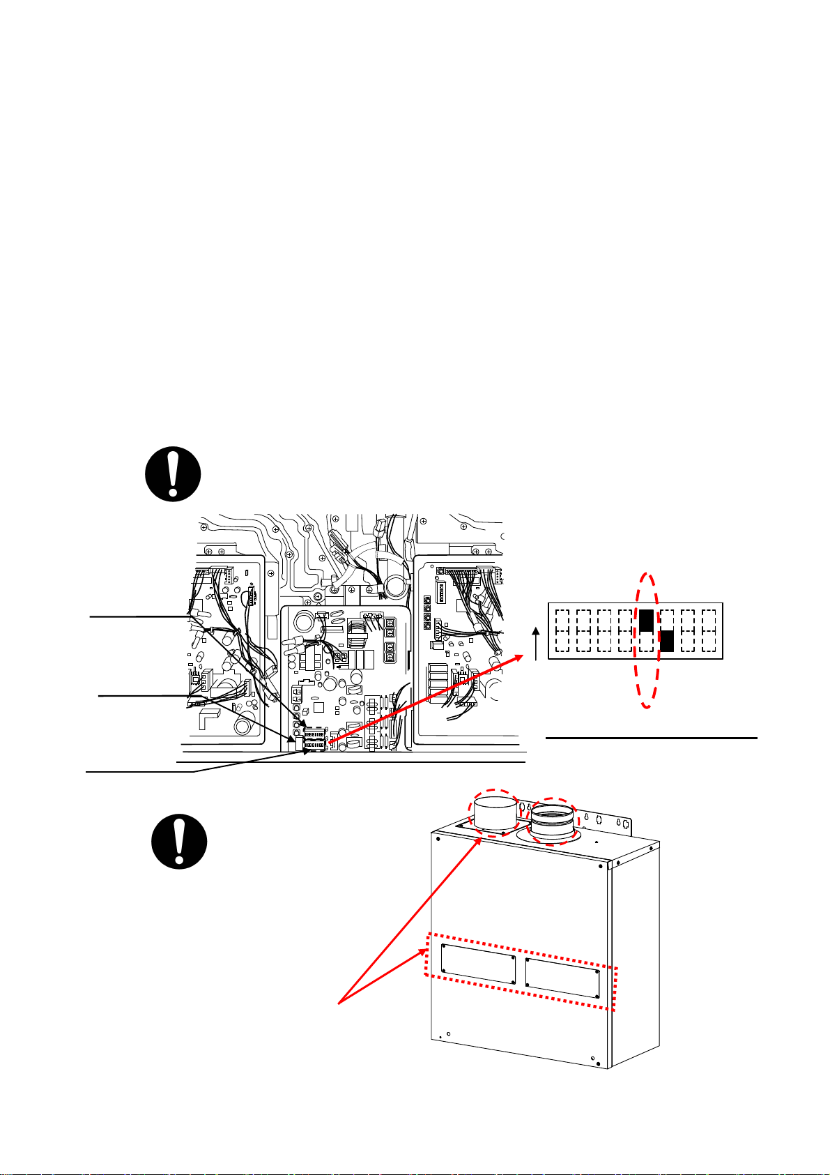
DIRECT INTAKE VENT SYSTEM
This water heater may be converted to a direct-vent (sealed combustion) appliance by installing
an adapter (Part No. 9007669005 (TM-DV50)) which will bring all requir ed combustible air from
outside the building. When installing the direct-vent conv ersion kit, p lease follow al l instructions
included with the kit.
The water heater must be installed in a location where the proper amount of combustible
air will be available to it at all times without obstructions.
If used as a direct-vent appliance, the water h eater requires a 5” combustible air supply
pipe. The intake pipe must be sealed airtight.
Air supply pipe can be made of ABS, PVC, galvanized steel, corrugated aluminum,
corrugated stainless steel or Category III stainless steel.
Change the dipswitch settings to the direct-vent system. (See diagram below)
Sidewall venting is recommended for the direct-vent system.
The manufacturer recommends running the exhaust vent and the intake pipe parallel.
Upper bank of
dipswitches
Make sure power to the unit is
turned OFF before changing
the dipswitch settings.
The dark square is the direction
the dipswitch should be set to.
1 2 3 4 5 6 7 8
O
N
7-Seg LED
TMP1
TMP2
TMP3
MODE
DIRE
OUT
P-ALARM
Lower bank of
dipswitches
Lower Bank of Dipswitches
INTAKE
EXHAUST
MST
Direct-Vent
Conversion Kit
DIRECT-VE NT
CONVERSION KIT
LOUVER COVER PLATES
- 11 -
Page 12
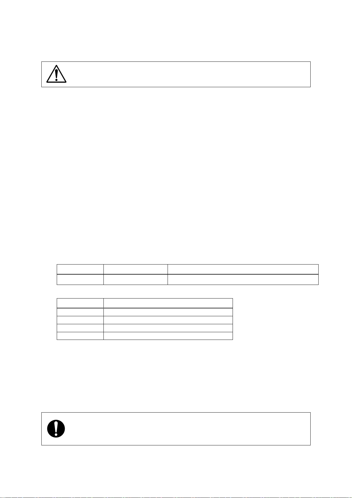
VENTING INSTRUCTIONS
This water heater must be vented in accordance with the sec tion “Venting of Equipment" o f the
latest edition of the Natural Fuel Gas Code: ANSI Z223.1, all applicable loc al building codes,
and Section 7 of CAN/CSA B149.1 Natural Gas in Canada, Propane Installation Code in
Canada.
WARNING: Improper venting of this appliance can result in excessive levels of
carbon monoxide which can result in severe personal injury or death.
EXHAUST VENT
This is a Category III appliance and must be vented accordingly. The vent system must be
sealed airtight. All seams and joints without gaskets must be sealed with high heat res istant
silicone sealant or UL listed aluminum adhesive tape ha ving a minimum temperature rating of
350 ºF. For best results, a vent system should be as short and straight as possible.
1. This water heater is a Category III appliance and must be vented accordingly with an y 5”
vent approved for use with Category III or Special BH type gas vent.
2. The manufacturer recommends the NovaVent line. However, the following are also UL
listed manufacturers: ProTech Systems Inc. (FasNSeal), Metal-Fab Inc., and Heat-Fab Inc.
(Saf-T Vent).
3. Follow the vent pipe manufacturer’s instructions when installing the vent pipe.
4. Do not common vent this appliance with any other vented appliance. (Do not
terminate vent into a chimney. If the vent must go through the chimney, the vent must run
all the way through the chimney with Category III approved or Special BH vent pipe.)
5. The maximum length of exhaust vent piping must not exceed 50 ft. deducting 5 ft. for each
elbow used in the venting system. Do not use more than 5 elbows.
Diameter Max. No. of Elbows Max. Vertical or Horizontal Length
*For each elbow added, deduc t 5 ft. from max. vent len gth.
6. When the horizontal vent run exceeds 5 ft., support the vent run at 3 ft. intervals with
overhead hangars.
7. The manufacturer will not be responsible for any damage to the water heater caused by
condensation from the vent. For horizontal runs, slope the vent run downwards toward the
vent terminal at a rate of ¼” per foot. For horizontal runs that do not slope down ward and
for vertical runs, installing a condensate drain is recomme nded. Please refer to p. 14 for
the diagrams.
5” 5 Ea. 50 ft
No. of Elbows Max. Vertical or Horizontal Length
0 50 ft.
1 45 ft.
2 40 ft.
5 25 ft.
When installing the vent system, all applicable national and local codes must be
followed. If you install thimbles, fire stops or other protective devices and they
penetrate any combustible or noncombustible construction, be sure to follow all
applicable national and local codes.
- 12 -
Page 13
VENT TERMINATION
WARNING: Improper installation can cause nausea or asphyxiation, severe injury
or death from carbon monoxide and flue gases poisoning. Improper installation
will void product warranty.
The vent termination provides a means of instal ling vent pipe through the building wall and
must be located in accordance with ANSI Z223.1/NFPA 54, or in Canada with CAN/CSAB149.1 and local applicable codes.
A proper sidewall vent termination is recommen ded when the w ater heat er is v ented through
a sidewall. If the water heater is converted to a direct-vent unit, a proper sidewall direct-vent
termination is to be used.
General rules for venting the water heater are:
1. Place the water heater as close as possible to the vent termination.
2. The vent collar of the water heater must be fastened directly to an unobstructed vent pipe.
3. Do not weld the vent pipe to the water heater collar.
4. Do not cut the vent collar of the unit.
5. The weight of the vent stack must not rest on the water heater.
6. The vent must be easily removable from the top of the water heater for normal service and
inspection of the unit.
7. The water heater vent must not be connected to any other gas appliance or vent stack.
8. Avoid locating the water heater vent termination near any air intake devices. These fans
can pick up the exhaust flue products from the water heater and return them to the building.
This can create a health hazard.
9. Avoid using an oversized vent pipe or using extremely long runs of the pipe.
10. Locate the vent termination so that it cannot be blocked by any debris, at any time. Most
codes require that the termination be a t least 12 inche s above grade, but the installer may
determine if it should be higher depending on the job site condition and applicable codes.
11. For rooftop venting, a rain cap must be installed.
- 13 -
Page 14
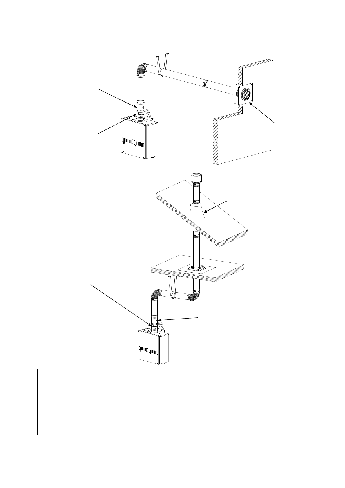
Horizontal Installation Diagram
Vertical condensation drain
(Install according to local codes)
Vent damper
(Recommended for freezing
weather conditions: 36°F and
below)
Vertical Installation Diagram
Vent damper
(Recommended for freezing
weather conditions: 36°F and
below)
Roof
Rain cap
Roof flashing
Vertical condensation drain
(Install according to local codes)
Wall
Sidewall
vent
termination
Regarding the clearance from the terminal to the air inlet or opening, refer to the next page.
Install a condensation drain in the venting.
Follow the vent manufacturer’s instructions and local codes.
Do not common vent or connect any vent from other appliances to the water heater vent.
Use 5” category III approved or Special BH, single or double wall stainless steel vent pipe.
- 14 -
Page 15
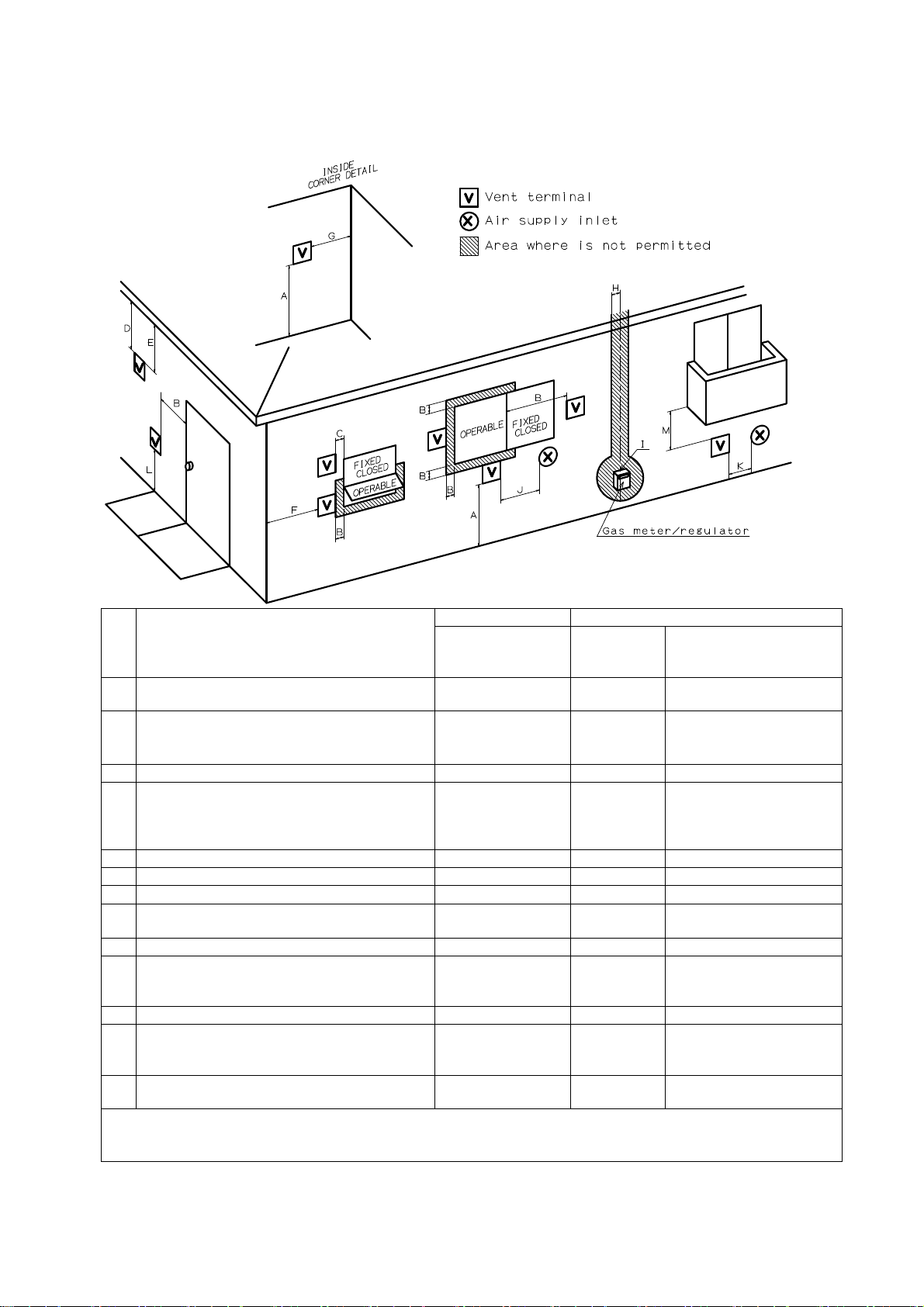
VENT CLEARANCES
Canada U.S.A
Clearance above gra d e, v era nd a, porch,
A
deck, or balcony.
Clearance to window or door that may be
B
opened.
Clearance to permanently closed window * * *
C
Vertical clearance to ventilated soffit
located above the vent terminator within a
D
horizontal distance of 2 feet (61cm) from
the center line of the terminator.
Clearance to unventilated soffit * * *
E
Clearance to outside corner * * *
F
Clearance to inside corn e r * * *
G
Clearance to each side of center line
H
extended above meter/regulator assembly
Clearance to service regu l ator vent outlet. 3 feet * *
I
Clearance to non-mechanical air supply
inlet to building or the combustion air inlet
J
to any other application.
Clearance to mechanical air supply inlet. 6 feet 3 feet 3 feet
K
Clearance above paved sidewalk or
paved driveway located on public
L
property.
Clearance under v er a nda, porch deck, or
M
balcony.
*For clearances not specified in ANSI Z223.1 / NFPA 54 or CAN/CSA-B149.1, please use clearances in
accordance with local ins tallation codes and the requirement of the gas supplier.
Direct vent and
other than Direct
Vent
1 foot 1 foot 1 foot
3 feet 1 foot
* * *
3 feet * *
3 feet 1 foot
7 feet * 7 feet
1 foot * *
Direct vent Other than Direct Vent
4 feet from below or
side opening. 1 foot
from above opening.
4 feet from below or
side opening. 1 foot
from above opening.
- 15 -
Page 16
GAS SUPPLY AND GAS PIPE SIZING
1. Turn off all electric power to the water heater if service is to be performed.
2. Turn the manual gas valve located on the outside of the unit clockwise to the off position.
WARNING: Conversion of this unit from natural gas to propane or vice versa will
void all warranty. Contact your local distributor to get the correct unit for your gas
type. The manufacturer is not liable for any property and/or personal
damage resulting from gas conversions.
*Check that the type of gas matches the rating plate first.
The minimum and maximum inlet gas pressures are:
Gas type Inlet gas pressure
Natural Gas Min. 5.0” WC – Max. 10.5” WC
Propane Min. 8.0” WC – Max. 14.0” WC
Inlet gas pressures that fall outside the range of values listed above may adversely affect the
performance of the water heater. These pressures are measured when the water heater is in full
operation.
TO TURN OFF GAS TO APPLIANCE
Inlet gas pressure must not exceed the above maximum values; gas pressure above the specified
range will cause dangerous operating conditions and da mage to the unit. Ensure that any and all
gas regulators used are operating properly and are providing gas pressures within the specified
range shown above.
Until testing of the main gas line supply pressure is completed, ensure the gas line to the water
heater is disconnected to avoid any damage to the water heater.
-Gas connections-
1. Install a manual gas shutoff valve between the water heater and the gas supply line.
2. When the gas connections are completed, it is necessary to perform a gas leak test either by
applying soapy water to all gas fittings and observing for bubb les or by using a gas leak detection
device.
The water heater and its individual shutoff valve must be disconnected from the gas supply
piping system during any pressure testing of that system at test pr essures in excess of 1/2 psi
(3.5 kPa).
The water heater must be isolated from the gas supply piping system by closing its individual
manual shutoff valve during any pressure testing of the gas supply piping system at test
pressures equal to or less than 1/2 psi (3.5kPa).
3. Always purge the gas line of any debris and/or water before connecting to the gas inlet.
NOTICE
Size the gas pipe appropriately to supply the necessary volume of gas required for the
water heater using ANSI Z223.1/NFPA 54 in the USA or CAN/CSA B149.1 in Canada
or local codes. Otherwise, flow capabilities and output temperatures will be limited.
- 16 -
Page 17
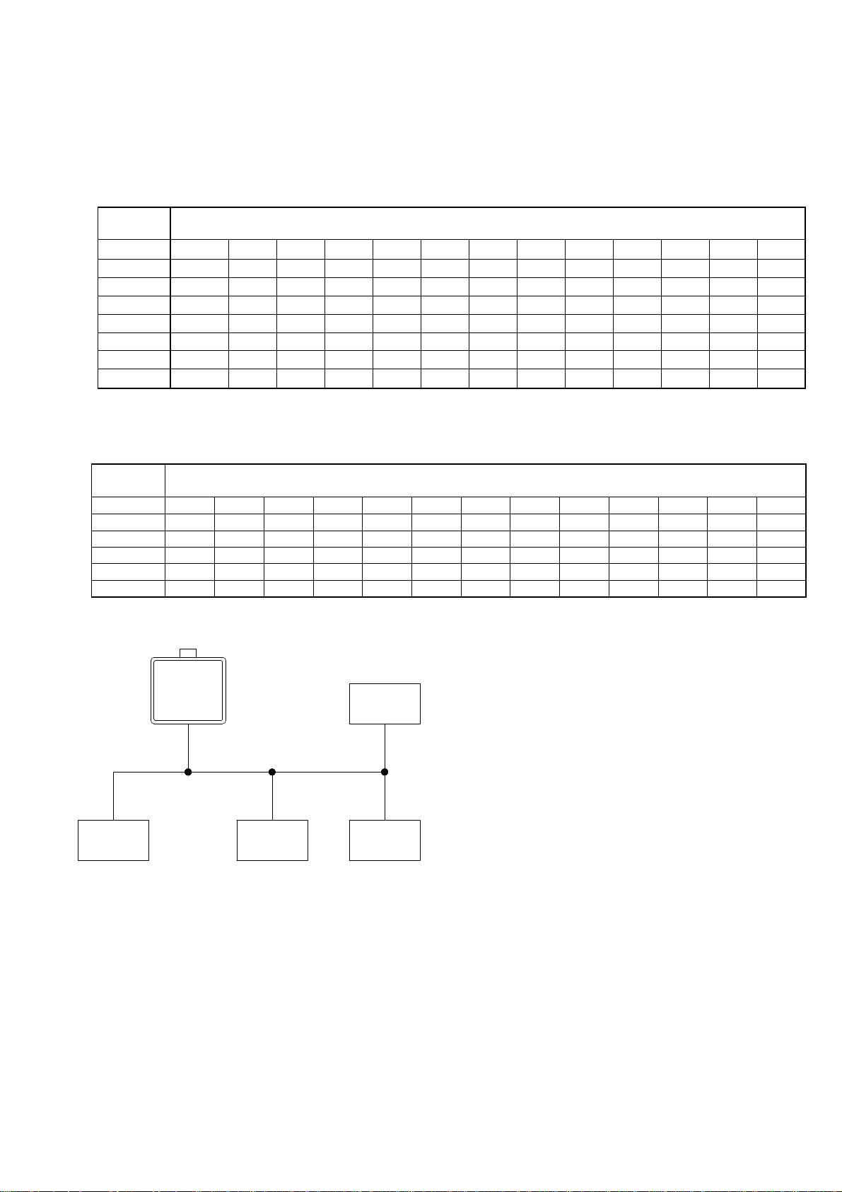
Natural Gas Supply Piping
Maximum Delivery Capacity of Cubic Feet of Gas per Hour of IPS Pipe Carrying Natural Gas of 0.60 Specific Gravity
Based on Pressu re Drop of 0.5” WC
Based on Energy Content of 1,000 BTU/Cubic Ft.: 910 (T-M50) requires 380 Cubic Ft./hr. Unit: Cubic Feet per Hour
Pipe
Size
Length
Diameter 10' 20' 30' 40' 50' 60' 70' 80' 90' 100' 125' 150' 200'
¾”
1”
1 ¼”
363 249 200 171 152 138 127 118 111 104 93 84 72
684 470 377 323 286 259 239 222 208 197 174 158 135
1,404 965 775 663 588 532 490 456 428 404 358 324 278
1 ½” 2,103 1,445 1,161 993 880 798 734 683 641 605 536 486 416
2”
2 ½”
3”
4,050 2,784 2,235 1,913 1,696 1,536 1,413 1,315 1,234 1,165 1,033 936 801
6,455 4,437 3,563 3,049 2,703 2,449 2,253 2,096 1,966 1,857 1,646 1,492 1,277
11,412 7,843 6,299 5,391 4,778 4,329 3,983 3,705 3,476 3,284 2,910 2,637 2,257
Propane (LP) Gas Supply Piping
Maximum Capacity of Propane (LP) Gas Based on 11” WC supply pressure at a 1.0” WC pressure drop
Pipe
Size
Length
Diameter 10’ 20’ 30’ 40’ 50’ 60’ 70’ 80’ 90’ 100’ 125’ 150’ 200’
¾”
1”
1 ¼”
1 ½”
2”
10’ Length
1-1/2” Pipe Size
10’ Length
1-1/2” Pipe Size
Gas Meter
567 393 315 267 237 217 196 185 173 162 146 132 112
1,071 732 590 504 448 409 378 346 322 307 275 252 213
2,205 1,496 1,212 1,039 913 834 771 724 677 630 567 511 440
3,307 2,299 1,858 1,559 1,417 1,275 1,181 1,086 1,023 976 866 787 675
6,221 4,331 3,465 2,992 2,646 2,394 2,205 2,047 1,921 1,811 1,606 1,496 1,260
Based on Energy Content of 1,000BTU/Cubic Ft:
Divide each appliance’s BTU requirement by 1,000BTU to get
the appliances Cubic Ft. requirement.
Take into account the distance the appliance is from the gas
meter, look in the above gas chart to properly size the line.
For sections of the gas line supplying gas to more than one
appliance (Ex: Point A to Point B), add up the cubic ft.
requirements of the appliances that are being supplied by that
section, and size to the farthest appliance.
For Example: The section from A to B supplies gas to the
furnace, range, and dryer. Adding up the BTU requirements and
dividing by 1,000 yields a cubic ft. requirement of 220 cubic ft. of
gas. The farthest appliance is the range, which is 60 ft. away
from the meter. Looking at the above chart, and under the
column of 60ft., Section A to B needs to be 1” in order to supply
220 cubic ft.
Water
Heater
380,000BTU
20’ Length
1-1/4” Pipe Size
A
10’ Length
1” Pipe Size
Gas Sizing Example
(Natural Gas)
15’ Length
B
3/4” Pipe Size
10’ Length
3/4” Pipe Size
Furnace
120,000BTU
Dryer
35,000BTU
10’ Length
1/2” Pipe Size
15’ Length
1/2” Pipe Size
Range
65,000BTU
Unit: kBTU per Hour
- 17 -
Page 18
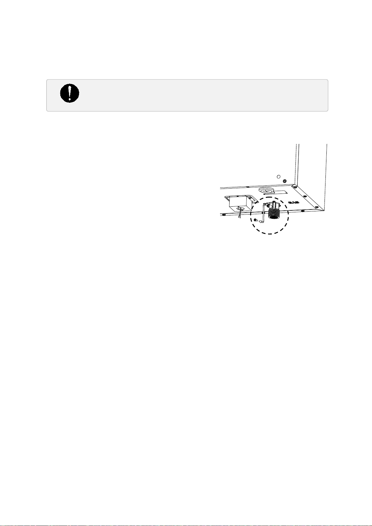
-Measuring inlet gas pressure-
The water heater cannot perform properly without sufficient inlet gas pressure. Below are
instructions on how to check the inlet gas pressure. THIS IS ONLY TO BE DONE BY A
LICENSED PROFESSIONAL.
1. Shut off the manual gas valve on the supply gas line.
2. Remove the screw for the pressure port located
on the gas inlet of the water heater shown in the
diagram to the right.
3. Connect the manometer to the pressure port.
4. Re-open the manual gas valve. Check to see that
there are no gas leaks. Open some of the
fixtures that use the highest flow rate to turn on
the water heater.
5. Check the inlet gas pressure. When the water
heater is on maximum burn, the manometer
should read from 5.0” to 10.5” WC for Natural
gas, from 8.0” to 14.0” WC for Propane.
1. Turn off all electric power to the water heater if service is to be performed.
2. Turn the manual gas valve located on the outside of the unit clockwise to
the off position.
- 18 -
Page 19
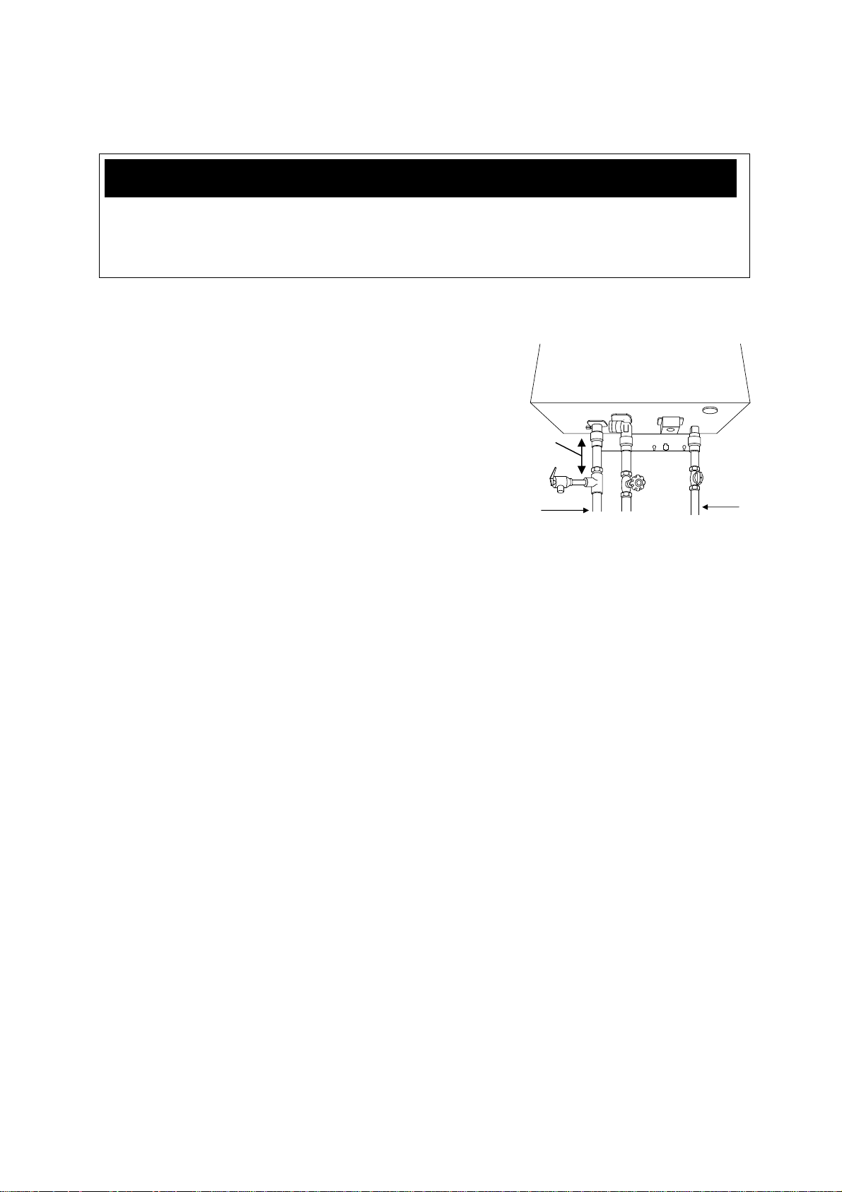
WATER CONNECTIONS
A
・Do not use this water heater if any part has been submersed under water. Immediately call a
licensed professional to inspect the water heater and to replace any damaged parts.
・Do not reverse the hot outlet and cold inlet connections to the water heater. This will not
activate the water heater.
All pipes, pipe fittings, valves and other components, including soldering materials, must be
suitable for potable water systems.
1. All pipes, pipe fittings, valves and other
components, including soldering materials, must
be suitable for potable water sy st ems .
2. A manual shut off valve must be installed on the
cold water inlet to the water heater between the
main water supply line and the water heater.
3. In addition, a manual shut off valve is also
recommended on the hot water outlet of the un it.
If the water heater is installed within, or subjected
to, a closed loop water system, a thermal
expansion tank must be installed.
4. Before installing the water heater, flush the water
line to remove all debris, and after installation is
complete, purge the air from the line. Failure to
do so may cause damage to the heater.
5. There is a wire mesh filter within the cold inlet to trap debris from entering your heater.
This will need to be cleaned periodically to maintain optimum flow.
FOR YOUR SAFETY, READ BEFORE OPERATING:
s Close as
Possible
Pressure
Pressure
Relief
Valve
Relief
Valve
Hot out
Hot out
Cold inlet
Cold inlet
Gas
Gas
PRESSURE RELIEF VALVE
The water heater has a high-temperature shut off sw itch built in as a standard safety feature
(called a Hi-Limit switch) therefore a “pressure only” relief valve is required.
This unit does not come with an approved pressure relief valve.
An approved pressure relief valve must be installed on the hot water outlet.
The pressure relief valve must conform to ANSI Z21.22 or CAN 1-4.4 and installation must
follow local code.
The discharge capacity must be at least 380,000 BTU/h.
The pressure relief valve needs to be rated for a maximum of 150 psi.
The discharg e piping for the pressure relief valve must be directed so that the hot water
cannot splash on anyone or on nearby equipment.
Attach the discharge tube to the press ure relief v alve an d run the end of the tube to within
6" from the floor. This discharge tube must allow free and c omplete drainage without any
restrictions.
If the pressure relief valve installed on the water hea ter discharges periodically, this may
be due to a defective thermal expansion tank or defective pressure relief valve.
The pressure relief valve must be manually operated periodically to check for correct
operation.
No valve must be placed between the relief valve and the water heater.
When ASME model is installed, the pressure relief valve should be conformed and
installed in accordance with ASME code.
For the ASME model, the pressure relief valve must conform to and be installed in
accordance with ASME code.
- 19 -
Page 20
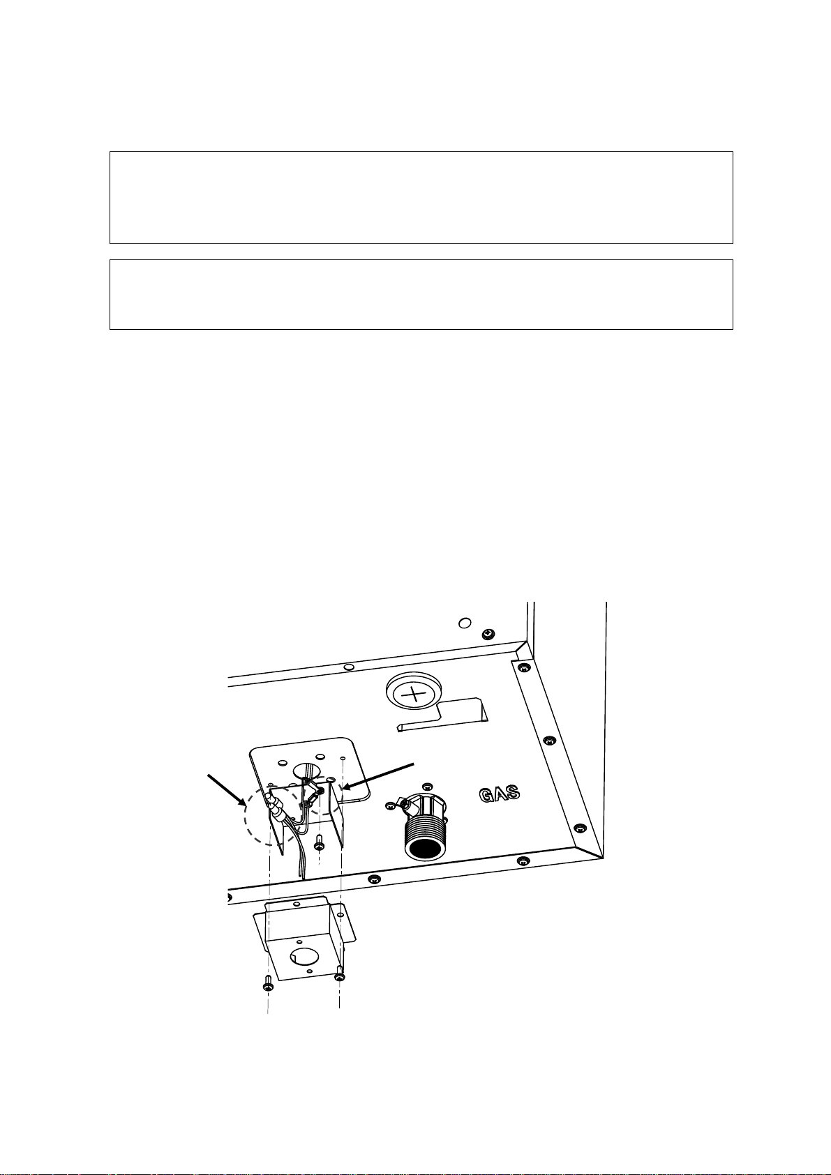
ELECTRICAL CONNECTIONS
WARNING: Follow the electrical code requirements of the local authority having
jurisdiction. In the absence of such requirements, follow the latest edition of the
National Electrical Code ANSI/NFPA 70 in the U.S. or the latest edition of CSA
C22.1 Canadian Electrical Code, Part 1, in Canada.
CAUTION: When servicing or replacing parts within the water heater, label all wires prior to
disconnection to facilitate an easy and error free reconnection. Wiring errors can cause
improper and dangerous operation. Verify proper operation after servicing.
1. The water heater must be electrically grounded. Do not attach the ground wire to either
the gas or the water piping.
2. The water heater requires 120 VAC / 60 Hz electrical pow er supply that is properly
grounded.
A proper disconnect (i.e. on/off switch, power plug, etc.) controlling the main power to
the water heater must be provided for service reasons. (Must comply with local
codes).
Connect the power supply to the water heater exactly as shown in the wiring diagram;
3. A green screw is provided in the junction box to ground the connection.
4. Can be hardwired or wired to a plug-in.
5. The use of a surge protector is recommended in order to protect the unit from power
surges.
Connect Power supply
120 VAC / 60 Hz
Ground
- 20 -
Page 21
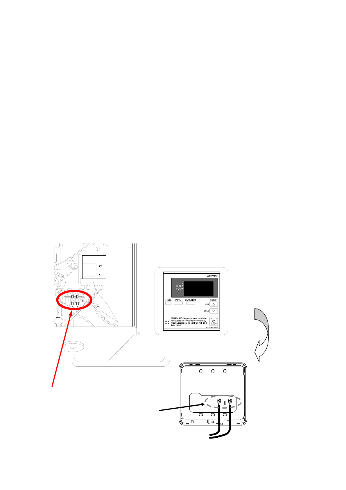
REMOTE CONTROLLER CONNECTION
1) Disconnect power supply from the water heater.
2) Take off the water heater’s fro nt cover .
3) Please find the remote control terminal using the diagram below (located around the lower
right-hand side of the water heater).
4) Open the plastic cover of the remote controller, and then attach the two fork terminals to
connector base of the backside of the remote controller with two screws. Make sure the
terminals are firmly fixed.
5) Put the remote wires through the hole on the bottom of the unit casing.
6) Connect the remote wires to the remote controller terminal properly (No polarity).
*Do NOT jump or short-circuit wires, or computer will be damaged.
7) Replace Front Cover securely.
8) Wires used for the remote controller connection must be:
Minimum 20 gauge wire (No polarity)
Maximum 400 feet long
*For details on the connection to the remote controller accessory, refer to the remote controller
Installation Manual.
Remote controller terminals of the water heater
Connect to these terminals
Connect other end to these terminals
Front of remote
Back of remote
- 21 -
Page 22
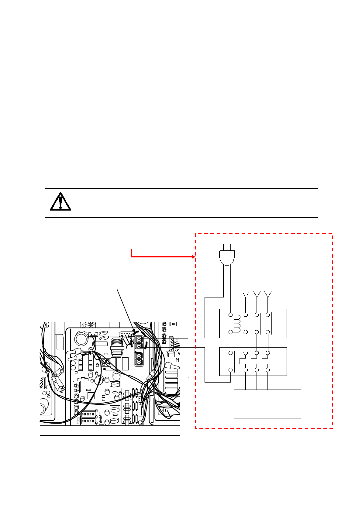
PUMP CONTROL CONNECTIONS
The water heater can be used to control a recirculation pump. Proper pump control helps to
preserve the life of the system and saves energy as well.
The water heater pump control port is a “normally-open dry contact”, and therefore needs
additional components to properly control a recirculation pump. To control the recirculation
pump, connect the pump to the “pump terminal” in the water heater as shown in the diagram
below. (In a multi-unit system, connec t the pump ONLY to the “PARENT” unit.) The pump is to
be connected using suitable relays shown in the diagram below (the pump terminal is
essentially only a dry contact. An external power supply and relays are required to
operate the pump).
Please make sure the relays are properly rated for the recirculation pump.
Using the water heater’s internal thermistors as a temperature control, the recirculation pump
will only turn on when recirculation is needed.
CAUTION: In a multi-unit system, the pump must be connected to the
“Pump” terminal in the “PARENT” unit only. If the pump is connected to
any of the “CHILD” units, the pump will not work.
These components are NOT included
with water heater and are external to the
unit. They must be a cquired separately.
Connect to this terminal.
This is the pump terminal.
Power supply for relay
Power supply for pump
120 VAC
220 VAC etc
120 VAC
220 VAC etc
for relay
Thermal relay
Recirculation
pump
- 22 -
Page 23
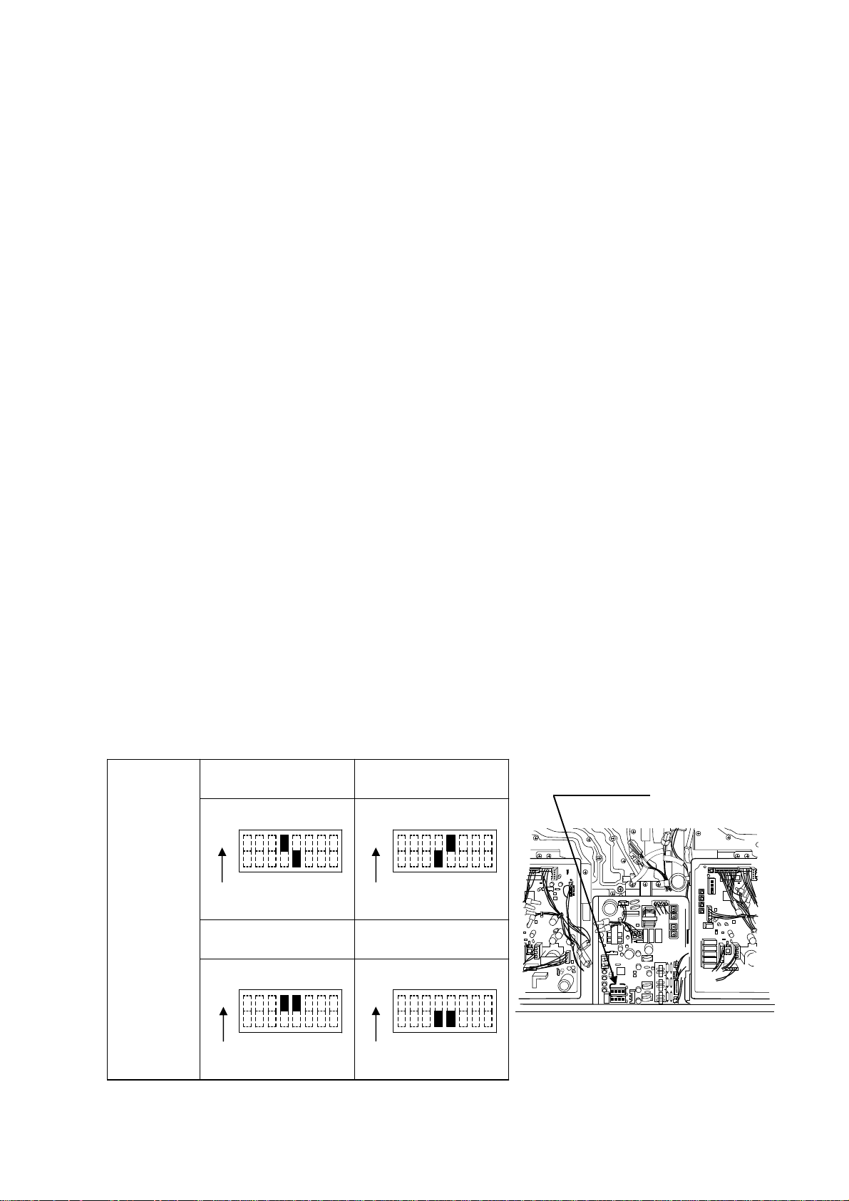
PUMP CONTROL MODE
The water heater provides the four types of the pump control modes. The pump control modes
are selected by changing dipswitch settings. The dipswitches a re located in the upper bank of
dipswitches in the lower-left quadrant of the ce ntral computer board in the water heater. (See
picture below)
A) Recirculation Control: No. 4 ON
This mode is for providing hot water as soon as possible like a recirculation usage. The pump
is only made to run while the temperature of the water in the re-circulation loop is not close to
the set temperature of the water heater. The pump will run for about 1 minute every 30
minutes to determine whether or not the water temperature in the whole recirculation loop is
lower than 9°F from the set temperature. If the water temperature is lower than 9°F from the
set temperature, the pump will remain running until the water in the loop gets up to the set
temperature. If not, the pump will stop for another 30 minutes. If the inlet thermistor senses
that the water temperature is lower than 9°F from the set temperature before those 30
minutes have elapsed, the pump will activate immediately and remain running until the water
in the loop gets up to the set temperature.
B) Storage Tank Circulation Control: No.5 ON
The water heater will heat the water 5.4°F higher than its set temperature (unless the water
heater is already set at its maximum temperature of 185°F). This is to ensure a higher rate of
recovery for storage tank applications. The circulation pump (from storage tank to water
heater) will always remain on.
C) Energy Conserving Recirculation: No.4 and No.5 ON
This pump control mode is similar to the “Recirculation Control mode”. How ever, once the
heat requirement is less than 7,440 BTU/h, the pump will turn off. The pump will activate
again when the temperature of the system is less than 95°F or after 20 minutes have elapsed
from its previous operation.
*If operating the pump in this mode, insulation is recommended on the water piping.
D) Normal Control (Default setting): No.4 and No.5 OFF
This provides no ON/OFF control for the pump. If a pump is connected to the pump control
terminal and both No.4 and No.5 are OFF, the p ump will be made to run all the time as long
as there is a power supply to the water heater (If the temperature remote controller is
installed, the pump will stop when the remote is turned off). Water in the loop will be
maintained at set temperature.
A) Recirculation
Control
1 2 3 4 5 6 7 8
O
N
RE-CIR
STORAGE
LP
D-PRT
P-RE
C) Energy Conserving
Recirculation
1 2 3 4 5 6 7 8
O
N
RE-CIR
Pump control modes
LP
STORAGE
P-RE
B) Storage Tank
Circulation Control
O
N
D) Normal Control
(Default)
O
N
D-PRT
1 2 3 4 5 6 7 8
RE-CIR
STORAGE
LP
1 2 3 4 5 6 7 8
LP
P-RE
RE-CIR
STORAGE
D-PRT
D-PRT
P-RE
Upper bank of
dipswitches
The dark squares indicate the direction
the dipswitches should be set to.
- 23 -
Page 24
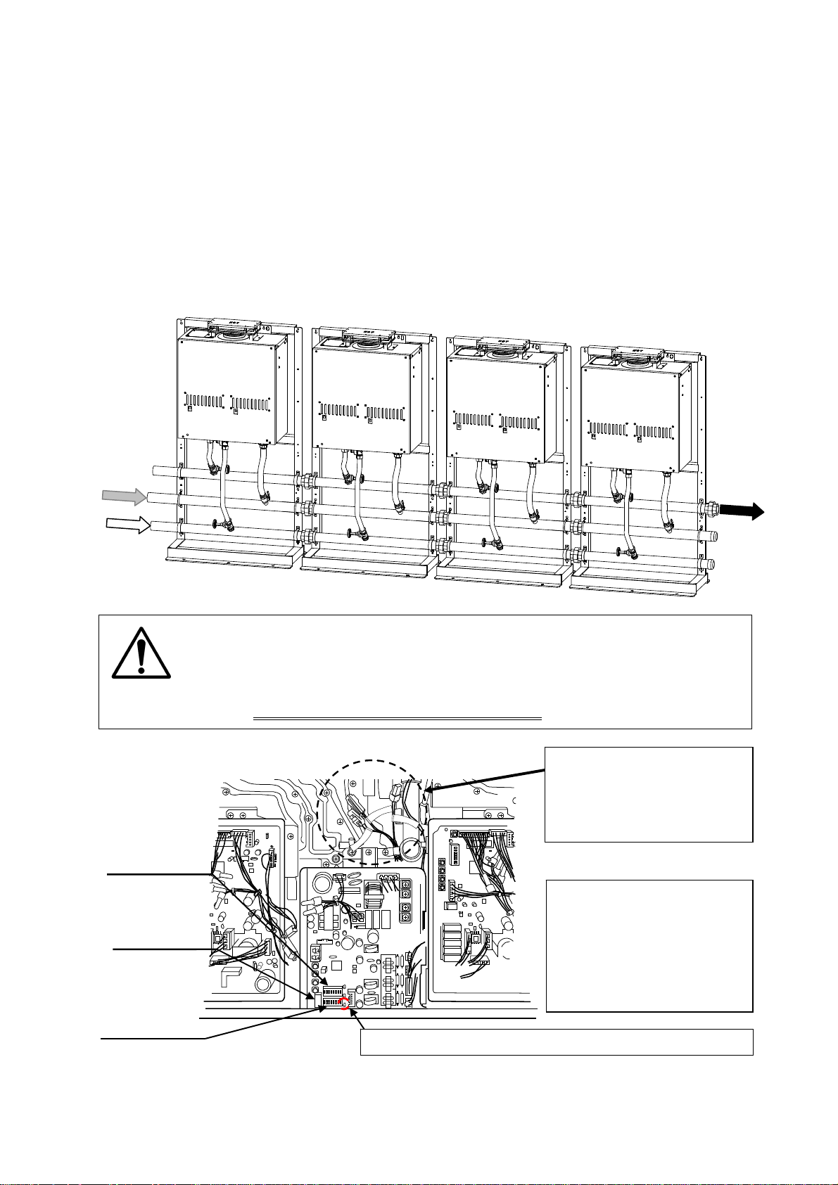
EASY-LINK SYSTEM
The water heater can be connected with other heaters of the same model with communication
cables to work as a multiple manifold system.
The Easy-Link system can connect up to 4 units.
A communication cable (gray color) comes with each unit. The cables use 18 gage wire
and can be up to 250ft. long all together.
You can manifold from 2 units to 4 units without a multi-system controller. A 4-unit system has
full automatic modulation between 15,000 BTU/h and 1,520,000 BTU/h.
Gas
Hot
Cold
CAUTION
Upper bank of
dipswitches
7-Seg LED
Lower bank of
dipswitches
The Easy-Link system is limited to 4 units. If you connect more than 4 units,
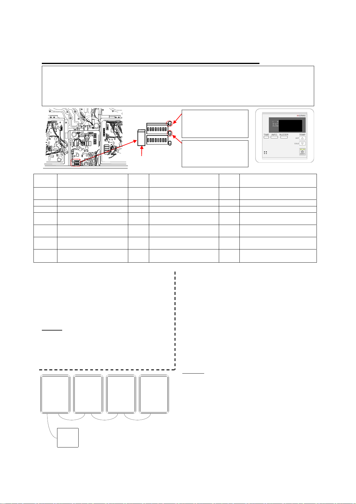
the first 4 units will work as part of the Easy-Link system, but the other
additional units will only work as individual units.
The water heater cannot be linked with other different tankless models
in the Easy-Link sys tem and Multi-Unit system
.
Easy-Link / Multi-unit
System connectors are
on each unit’s
computer board
To change the dipswitch
settings for the Easy-Link
system, locate the lower bank
of dipswitches to the right of
the 7-seg LED.
Do not adjust the upper
bank of dipswitches.
This lamp will flash when the unit is allowed the operation.
- 24 -
Page 25
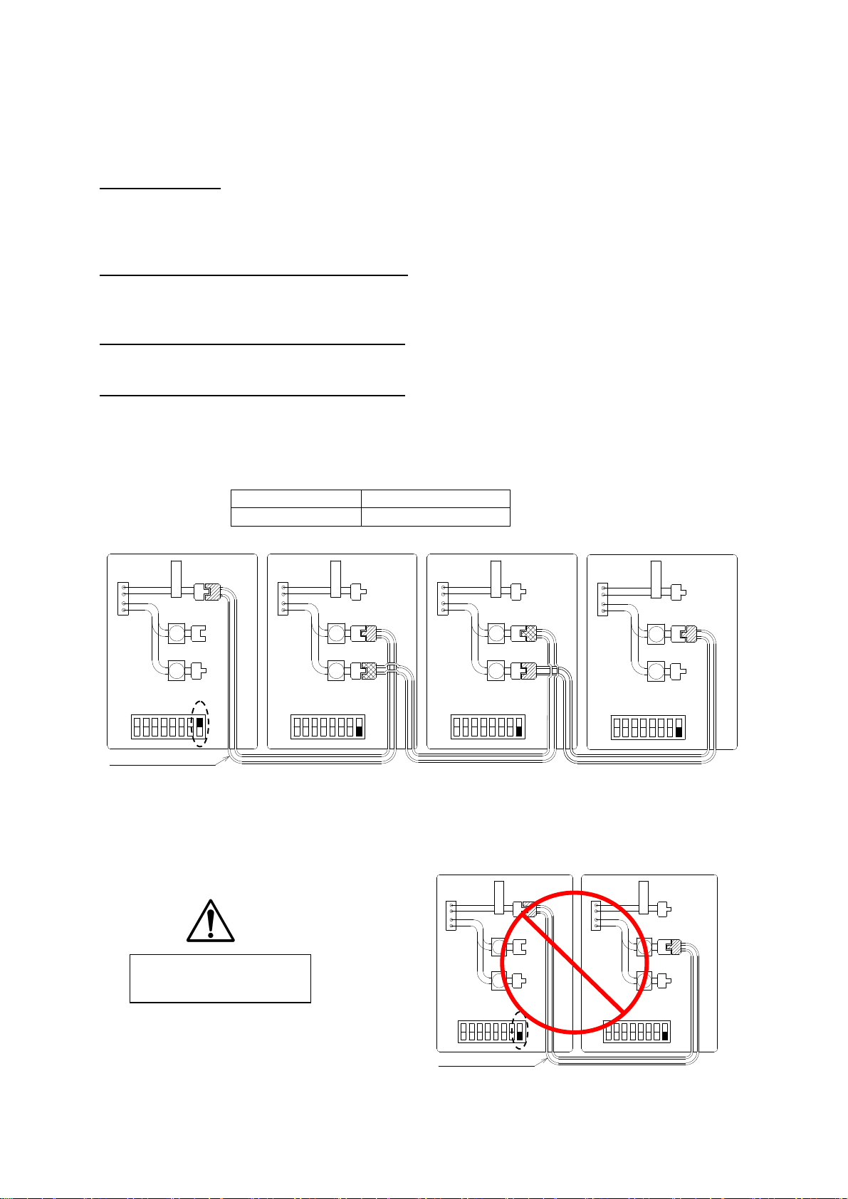
Easy-Link Connection Procedures
1. Choose one of your units as the “PARENT” unit.
2. “The PARENT”
Locate the lower bank of dipswitches to the right of the 7-seg. LED on the central
computer board of the unit that you select to be the “PARENT” unit. Change dipswitch No.
8 to “ON”. Do not change any of the dipswitches on the “CHILD” units.
3. Between the “PARENT” and the “CHILD-1”
Connect the “PARENT connector” of the “PARENT unit” to the “[1] connector” of the
“CHILD-1” unit.
4. Between the “CHILD-1” and the “CHILD-2”
Connect the “[2] connector” of the “CHILD-1” unit to the “[1] connector” of the “CHILD-2” unit.
5. Between the “CHILD-2” and the “CHILD-3”
Connect the “[2] connector” of the “CHILD-2” unit to the “[1] connector” of the “CHILD-3” unit.
6. Make sure the 7-seg. LED of all the unit’s computer boards display the unit #. The numbering
system automatically allocates the unit # to each water heater in the Easy-Link system, in
accordance with the table below.
Connectors
PARENT unit Unit # : 1
CHILD units Unit# : 2, 3 and 4
PARENT unit CHILD-1 unit CHILD-2 unit CHILD-3 unit
P
A
R
E
N
T
Connectors
P
A
R
E
N
T
Connectors
The dark squares indicat e t he dire c tio n
the dipswitches should be set to.
P
A
R
E
N
T
Connectors
P
A
R
E
N
T
11
11
11
11
Lower bank of Dipswitch
ON
OFF
Communication cable
22
5
4
3
6
2
1
7
Lower bank of Dipswitc h
8
ON
OFF
22
Lower bank of Dipswitch
2
1
3
5
4
7
6
8
ON
OFF
22
Lower bank of Dipswitch
5
1
6
4
3
2
7
8
ON
OFF
22
2
1
3
8
7
6
5
4
CAUTION
Unless you change dipswitch No. 8 of the “PARENT” unit to “ON”, the system will not
work as an Easy-Link system. The units will work as individual units.
Wrong dipswitch setting
on the “PARENT
” unit
PARENT unit CHILD-1 unit
Connectors Connectors
P
A
R
E
N
T
11
22
Lower bank of Dipswitch
1
2
ON
OFF
Communication cable
8
5
7
4
6
3
Lower bank of Dipswitch
1
2
4
3
ON
OFF
P
A
R
E
N
T
11
22
5
7
6
8
- 25 -
Page 26
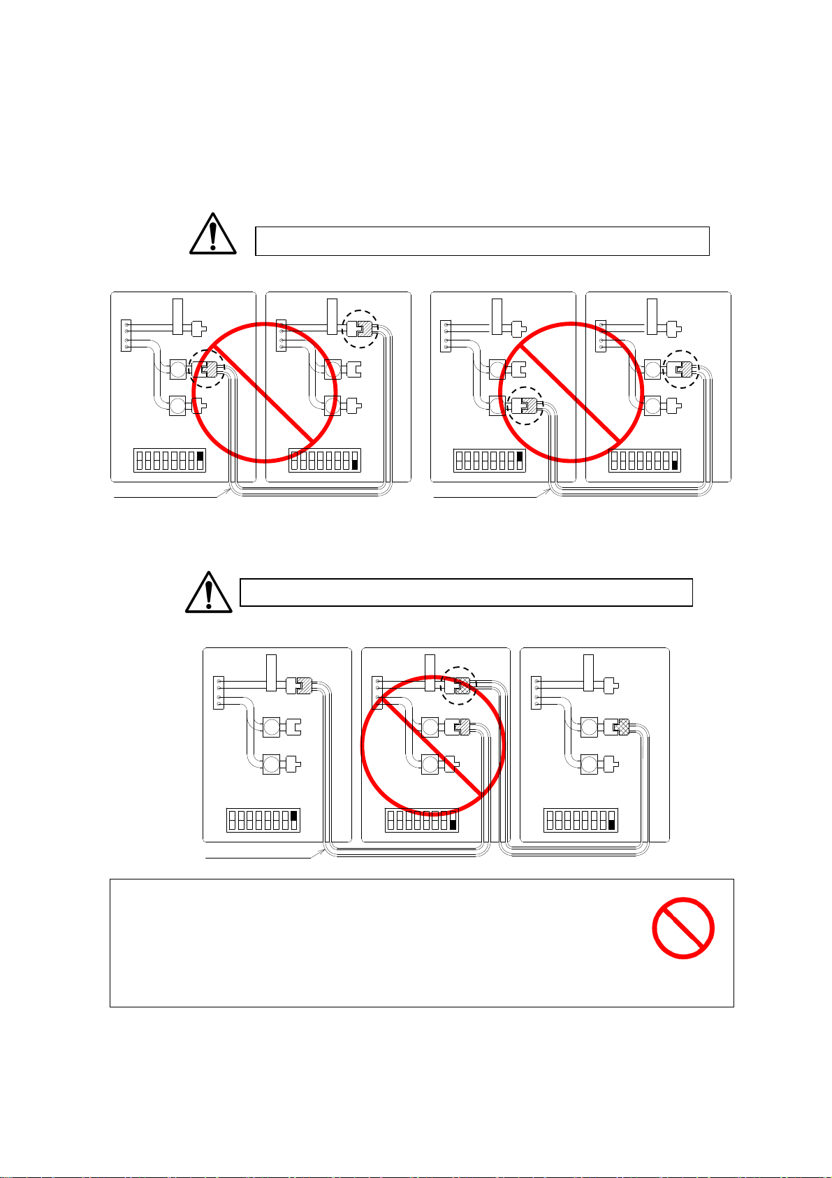
CAUTION
If you connect the “[1] (or [2]) connector” of the “PARENT” unit to the “PARENT (or [1])
connector” of the “CHILD-1” unit, the system will not work as the Easy-Link system. The units
will operate as individual units.
Wrong connection between the “PARENT” unit and the “CHILD-1” unit
PARENT unit CHILD-1 unit
Connectors Connectors
P
A
R
E
N
T
P
A
R
E
N
T
11
11
PARENT unit
Connectors Connectors
P
A
R
E
N
T
CHILD-1 unit
11
P
A
R
E
N
T
11
Lower bank of Dipswitch
ON
OFF
Communication cabl e
22
6
5
4
3
2
1
Lower bank of Dipswitch
8
7
ON
OFF
22
Lower bank of Dipswitch
3
2
1
6
5
4
8
7
ON
OFF
Communication c able
22
Lower bank of Di pswitch
2
1
5
3
4
8
6
7
ON
OFF
22
7
6
8
5
4
3
2
1
If you connect the “PARENT connector” of the “CHILD-1” unit to the “[1] connector” of the
“CHILD-2” unit, the “CHILD-2” unit will work as an individual unit, and will not be part of the
Easy-Link system.
Wrong connection between the “CHILD-1” unit and the “CHILD-2” unit
PARENT unit
Connectors Connectors Connectors
P
A
R
E
N
T
CHILD-1 unit
P
A
R
E
N
T
CHILD-2 unit
P
A
R
E
N
T
11
11
Lower bank o f Dipswitch
ON
OFF
Communicatio n cable
22
Lower bank of Dipswitch
8
5
7
6
2
4
3
1
ON
OFF
22
Lower bank of Dipswitch
8
5
1
2
7
6
4
3
1
2
3
4
ON
OFF
WARNING
Connecting two “PARENT connectors” together from two separate units may
damage the computer board. The communication cable has a female end
and a male end so it’s impossible to have a PARENT -to- PARENT
connection with the communication cable. Do not splice or modify
connectors.
- 26 -
11
22
8
5
7
6
Prohibited
Page 27
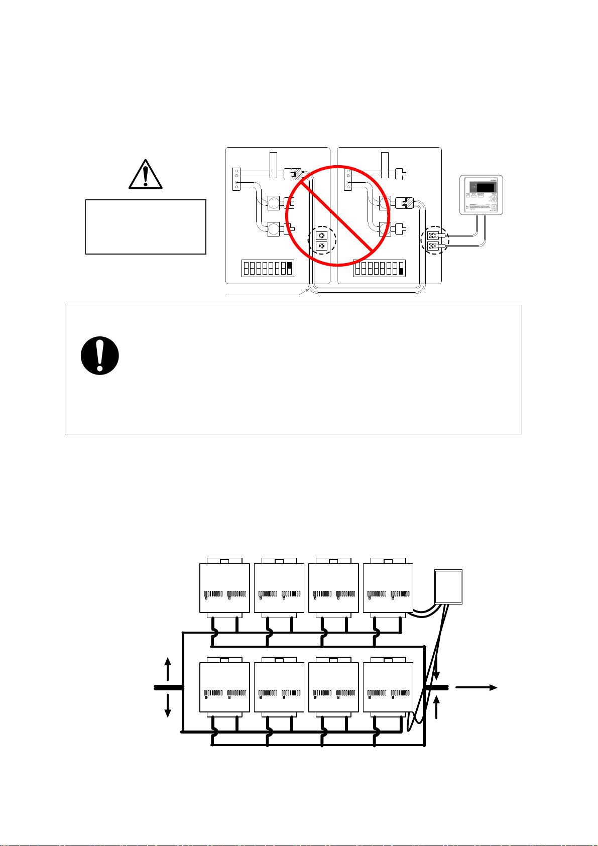
(
)
If a remote controller (optional) is used, it has to be connected to the “PARENT” unit. If the
remote controller is connected to a “CHILD” unit,
it will only control that particular individual
“CHILD” unit and will not control the Easy-Link system as a whole.
Wrong connection
between the “CHILD”
unit and the remote
controller
PARENT unit CHILD unit
Connectors Connectors
P
A
R
E
N
T
11
22
Lower bank of Dipswitch
1
2
3
ON
OFF
Communication cable
The remote controller is not required for the Easy-Link system.
If running the Easy-Link system without the remote controller, please make
8
7
4
6
5
Lower bank of Di pswitch
ON
OFF
P
A
R
E
N
T
Remote controller
11
22
3
2
1
4
6
5
8
7
sure the dipswitch settings for the temperature, outdoor, and direct-vent
settings on ALL the units are set to the same settings. Otherwise, the units
may not operate properly.
If the remote controller is used, the temperature on all the units in the
system will automatically be set to the same temperature that is set on the
remote. However, even with the remote, the outdoor and direct-vent
dipswitch settings still need to be set to the same settings on all the units.
MULTI-UNIT SYSTEM FOR LARGE VOLUMES
Multiple 910 (T-M50) models can be combined for a Multi-Unit system, along with the Mul tiple
Unit Controller and Remote Controller (Parts 9007675005 (TM-MC01) and 9007603005 (TMRE30)). Each set of controllers (Parts 9007675005 (TM-MC01) and 9007603005 (TM-RE30))
can control from 2 units to 10 units for commercial or residential applications. For a 10-unit
system, the computer can modulate between the usages of 15,000 BTU/h to 3.8 Million BTU/h.
Cold IN
910
(T-M50)
9007675005
TM-MC01
Hot Out
- 27 -
Page 28
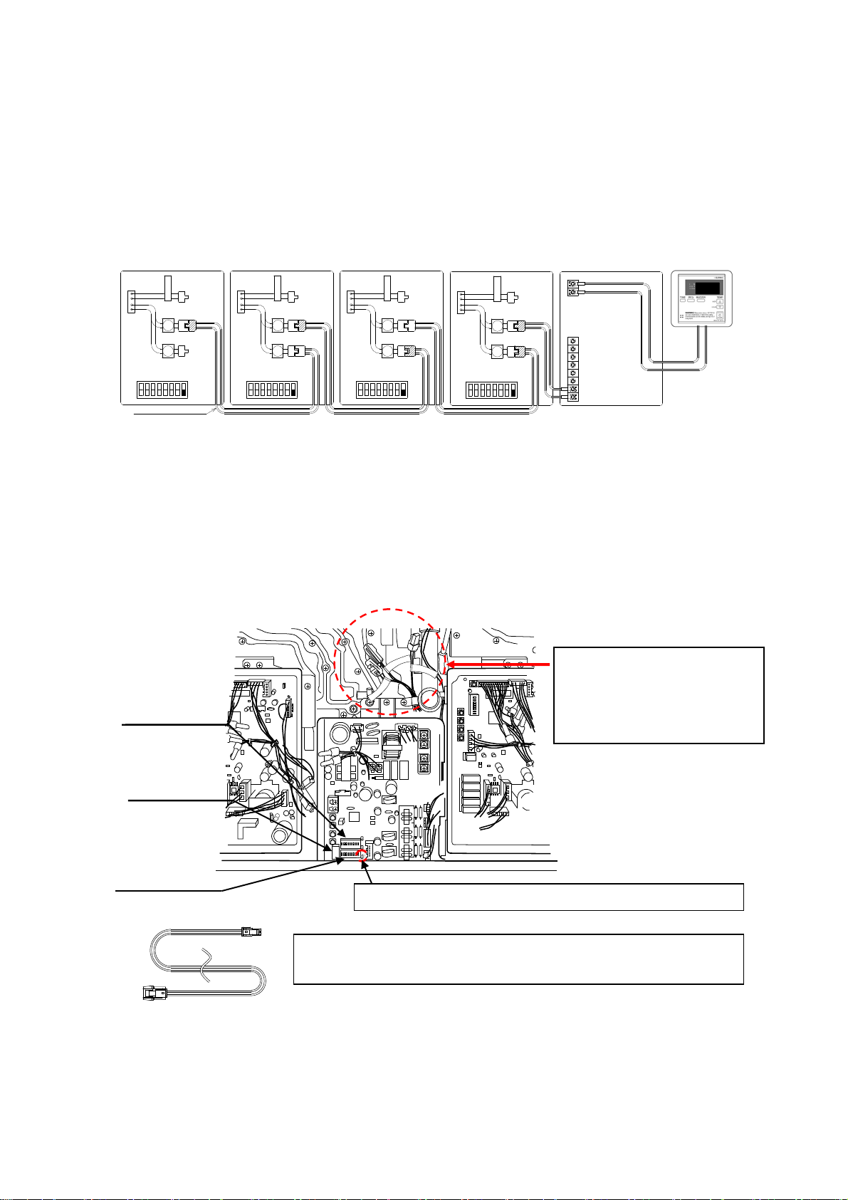
An individual cut-off switch is recommended for each unit in a multi-unit system for the purpose
of maintenance.
Multi-Unit System Connection Diagram
Multi-Unit Controller (9007675005 (TM-MC01)) and Temperature Remote Controller
(9007603005 (TM-RE30)) wiring:
Unit 1 Unit2 Unit3 Unit4
P
Connectors Connectors Connectors
A
R
E
N
T
11
22
Lower bank of Dipswitch
6
5
4
3
2
1
ON
OFF
Communication cable
8
7
Lower bank o f Dipswitch
P
A
R
E
N
T
11
22
Lower bank of Dipswitch
8
2
1
5
4
7
3
6
ON
OFF
4
1
3
2
ON
OFF
P
A
R
E
N
T
Connectors
11
22
6
5
8
7
Lower bank of Dipswitch
P
A
R
E
N
T
11
22
2
1
5
4
3
8
7
6
ON
OFF
9007675005
-
The above connection diagram is an example of how to connect 4 water heaters together in
a Multi-Unit System. Up to 10 water heaters can be connected in this fashion.
Make sure the “7-seg LED” of all the units’ computer boards display the unit #. The Multi-
Unit controller automatically allocates the unit # (1 to 10) to each water heater that is part of
the Multi-unit system.
9007603005
-
The dark squares indicate the direction the dipswitches should be set to.
Please refer to the Multi-Unit Controller manual for further instructions of the Multi-Unit system.
Upper bank of
dipswitches
7-Seg LED
Lower bank of
dipswitches
.
This lamp will flash when the unit is allowed the operation.
The Comunication Cables are included with the 910 (T-M50). The
Cables use 18 gage wire and can be up to 250 ft. long all together.
Easy-Link / Multi-unit
System connectors are
on each unit’s
computer board
- 28 -
Page 29
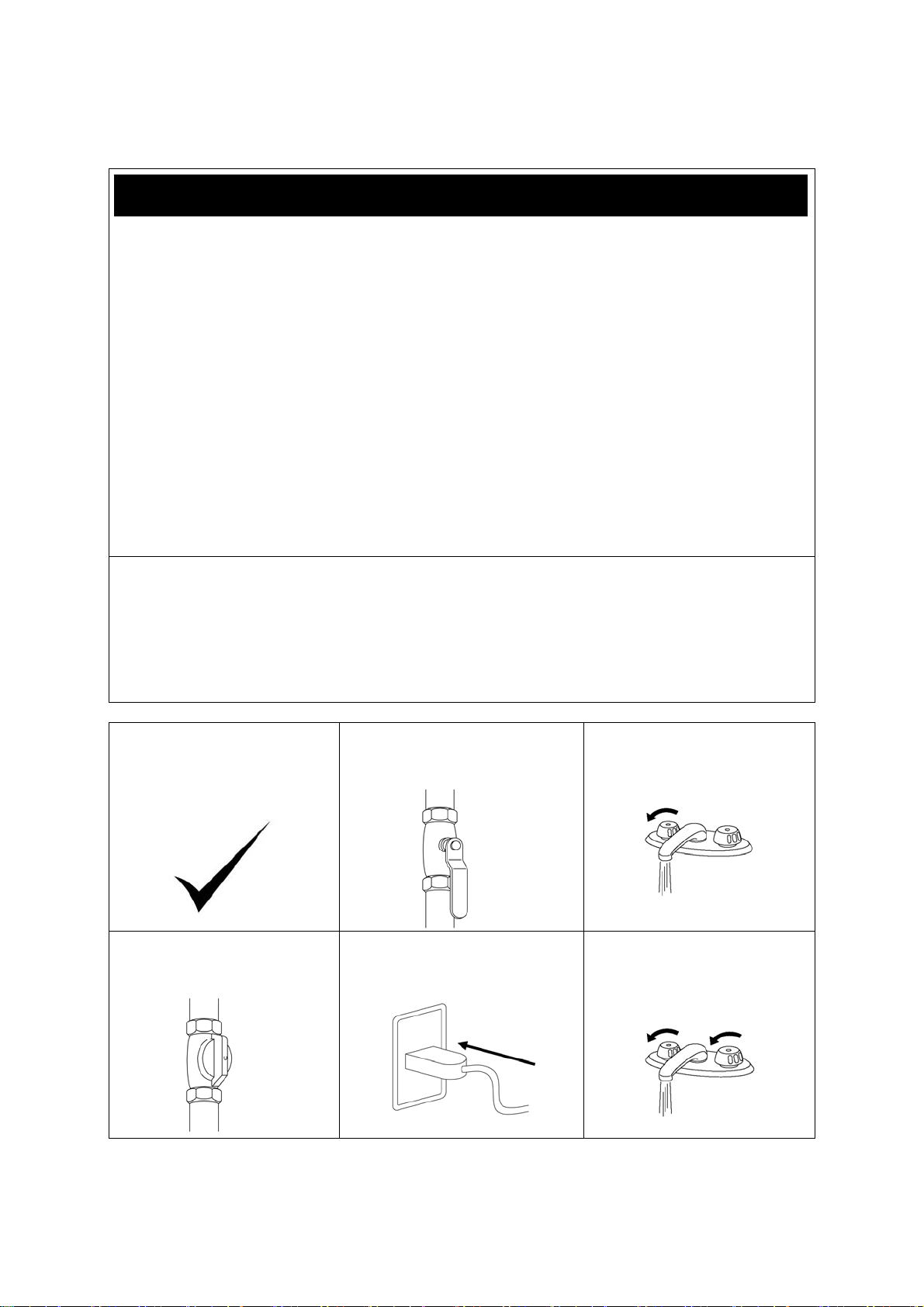
INITIAL OPERATION
Check the GAS and WATER CONNECTIONS for leaks before firing it for the first time.
Open the main gas supply valve to the unit using only your hand to avoid any spark.
Never use tools. If the knob will not turn by hand, do not try to force it; call a qualified
service technician. Forced repair may result in a fire or explosion due to gas leaks.
Be sure to check next to the bottom of the unit because some gases are heavier than air
and may settle towards the floor.
Check the GAS PRESSURE. Refer to p.16 .
Do not try to light the burner manually. It is equipped with an electronic ignition device
which automatically lights the burner.
Check for PROPER VENTING and COMBUSTIBLE AIR to the heater.
Purge the GAS and WATER LINES to remove any air pocket.
Do not use this water heater if any part has been submersed under water. Immediately call
a qualified service technician to inspect the water heater and to replace any damaged
parts.
FOR YOUR SAFETY, READ BEFORE OPERATING:
CAUTION: IF YOU SMELL GAS:
Do not try to start the water heater.
Do not touch any electric switch; do not use any phone in your building.
Immediately call your gas supplier from a neighbor’s phone. Follow the gas supplier’s
instructions.
If you cannot reach your gas supplier, call the fire department.
1. Once the above checks
have been completed,
please clean filter of any
debris. Refer to p. 34 for
instructions.
4. Fully open the manual
gas control valve
installed.
2. Fully open the manual
water control valve on the
water supply line.
3. Open a hot water tap to
verify that water is flowing
to that tap.
Then close the hot water tap.
5. Turn on the 120 volt 60 Hz
power supply to the water
heater.
6. Now you are ready to
enjoy hours of endless
hot water.
- 29 -
Page 30
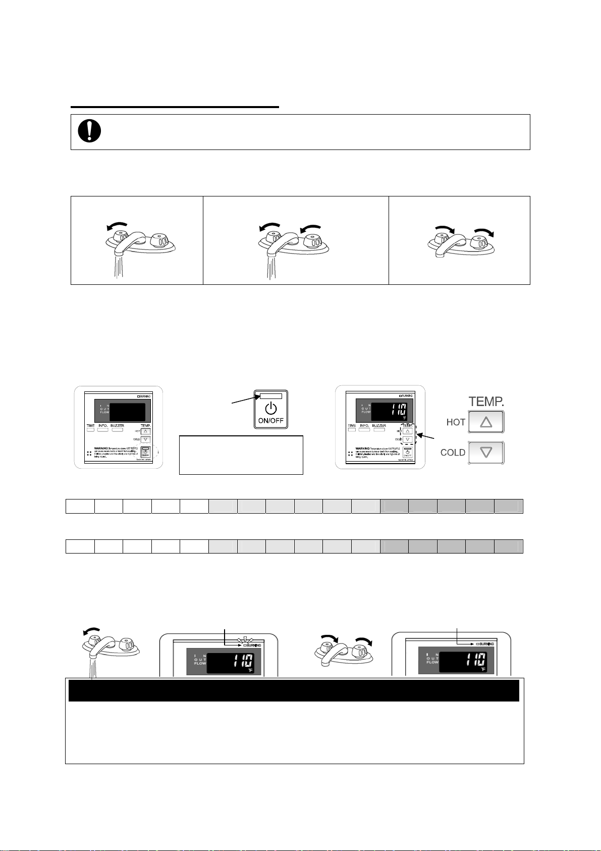
NORMAL OPERATION
Flow rate to activate the 910 (T-M50) : 0.5 gallon per minute
Flow rate to keep the 910 (T-M50) running : 0.4 gallon per minute
1. NORMAL OPERATION
WITHOUT REMOTE CONTROLLER
1.
Open a hot water tap.*
2. Mix cold water with the hot to get
the correct temperature water.
*If a remote controller installed, turn the remote controller ON by pressing the power ON/OFF button on the remote
controller and then set the temperature by pressing the HOT/COLD buttons before opening a hot water tap. The
temperature is displayed when the remote controller is turned ON.
2. NORMAL OPERATION
WITH REMOTE CONTROLLER INSTALLED: 9007603005 (TM-RE30) (Optional)
1. Press the power ON/OFF button. 2. Set temperature. (Example 110°F)
When ON,
green LED is lit.
The temperature and the
time will be displayed on
the remote controller.
3. Close the hot water tap.
Temperatures available under the Default Mode
100 105 110 115 120 125 130 135 140 145 150 155 160 165 170 175
Temperatures available under the High Temperature Mode
110 115 120 125 130 135 140 145 150 155 160 165 170 175 180 185
(unit:°F)
DO NOT set to 185°F if you use your water heater in recirculation system. Refer to p.33
3. Open a hot water tap.
Mix cold water with the hot if you need.
Lamp is ON
Lamp is ON
4. Close the hot water tap.
Lamp is OFF
Lamp is OFF
WARNING
Hot Water temperatures over 125F (52ºC) can cause severe burns instantly or d eath from
scalding.
The outlet hot water temperature of the water heater is factory set at 120F (49ºC).
Feel the water temperature before bathing or showering.
- 30 -
Page 31
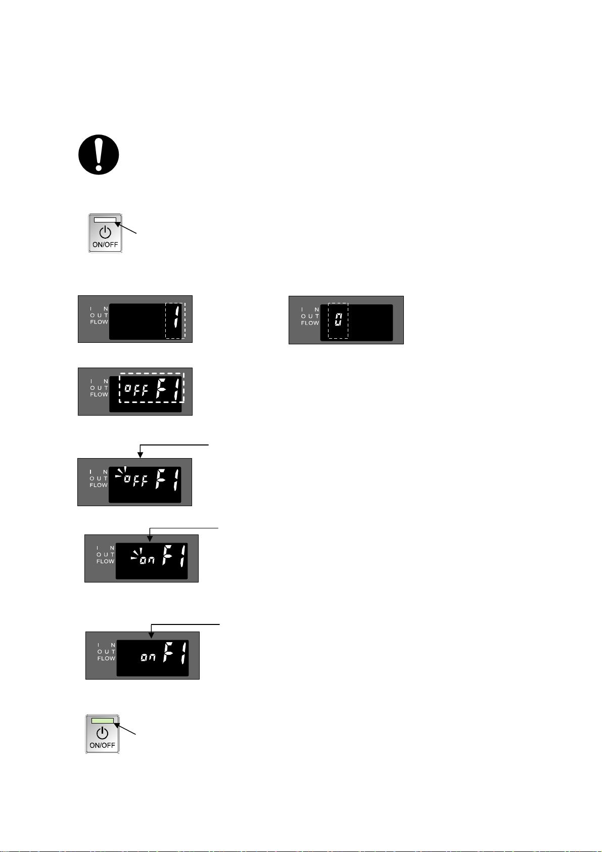
*To change the remote controller’s mode from Default Mode to High Temperature Mode,
please follow the procedures below (the remote controller must be installed prior to operating
these procedures):
DO NOT set to 185ºF if you use your water heater in a recirculation system.
This will cause damage to the heater and void the warranty.
1. Turn off power to the remote controller by pressing the “ON/OFF" button.
Lamp is OFF to indicate that power is off
2. Simultaneously press and hold both the “HOT” and “COLD” buttons for at least five seconds.
And then make sure “1” (or “0”) is displayed on remote controller.
“1” is displayed for single units “0” is displayed for Easy-Link / Multi-unit Systems
3. Press the “TIME” button.
Make sure OFF and F1 are displayed on remote controller.
4. Press the “INFO” button. After, make sure “OFF” blinks.
Blink
5. Press the “HOT” button or the “COLD” button to set display to “on”.
Blink
6. Simultaneously press both the “BUZZER” button and the “INFO” button to fix the setting.
7. Make sure display is no longer blinking.
Not blinking
8. Press the “ON/OFF” button to finish the setting.
9. Turn on power to the remote controller by pressing the “ON/OFF” button ag ain.
Lamp is ON
- 31 -
Page 32
FLOW
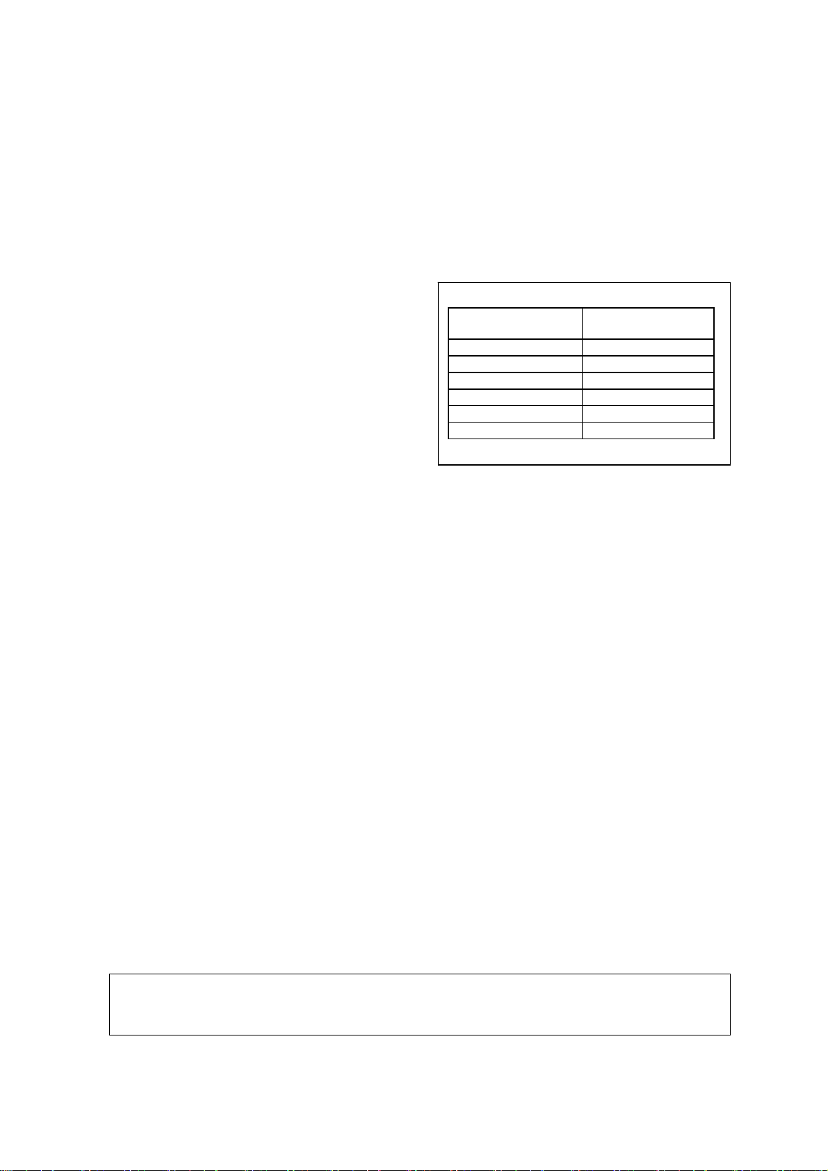
The flow rate through the water heater is limited to a maximum of 14.5 GPM.
The temperature setting, along with the supply temperature of the water will determine the
flow rate output of the unit.
Please refer to the temperature vs. gallons per minute chart on p.51 to determine the likely
flow rates based on your local ground water temperature and your desired outlet water
temperature combination.
Based on the United States Department of
Energy method of testing water heater output,
the water heater is rated for 474 gallons per
hour (GPH) or 7.9 gallons per minute (GPM)
for Natural Gas, and 504 GPH or 8.4 GPM for
Liquid Propane, when raising the water
temperature by 77F (from 58F to 135F).
Refer to the chart on the right for typical
household plumbing fixture flow rates to
determine what the water heater can do in a
household application.
Appliance / Use Flow Rate (GPM)
Lavatory Faucet 1.0
Bath Tub 4.0 – 10.0
Shower 2.0
Kitchen Sink 1.5
Dishwasher 1.5
Washing Machine 4.0
Taken from UPC 2006
Household Flow Rates
FREEZE PROTECTION SYSTEM
This unit comes equipped with heating blocks to pro tect it against damages associated with
freezing.
For this freeze protection system to operate, there has to be electrical power to the unit.
Damage to the heat exchanger caused by freezing temperatures due to power loss is not
covered under the warranty. In cases where power losses can occur, consider the use of a
backup power supply.
The freeze protection system will activate when the surrounding and/or outside temperatures
drop below 36.5°F (2.5°C).
In any areas subject to freezing temperatures, the manufacturer highly recommends
installing the unit indoors. In such an installation, freezing is sues can only occur if cold air
enters through the venting into the heat exchanger, whether by negative p ressures within the
installation location or by strong outside winds. It is the installer’s responsibility to be aware
of these issues and take all preventative measures. The manufacturer will not be responsible
for any damage to the heat exchanger as a result of freezing.
The manu facturer also high ly recommends the use of a backflow preventer (sold sepa rately)
to minimize the amount of cold air entering through the exhaust venting when the water
heater is off.
If you will not be using your heater for a long period of time:
1. Completely drain the water out of the unit. Refer to p. 34.
2. Disconnect power to your heater.
This will keep your unit from freezing and being damaged.
CAUTION: Only pipes within the water heater are protected by the freeze protection
system. Any water pipes (hot or cold) located outside the unit will not be protected.
Properly protect and insulate these pipes from freezing.
- 32 -
Page 33
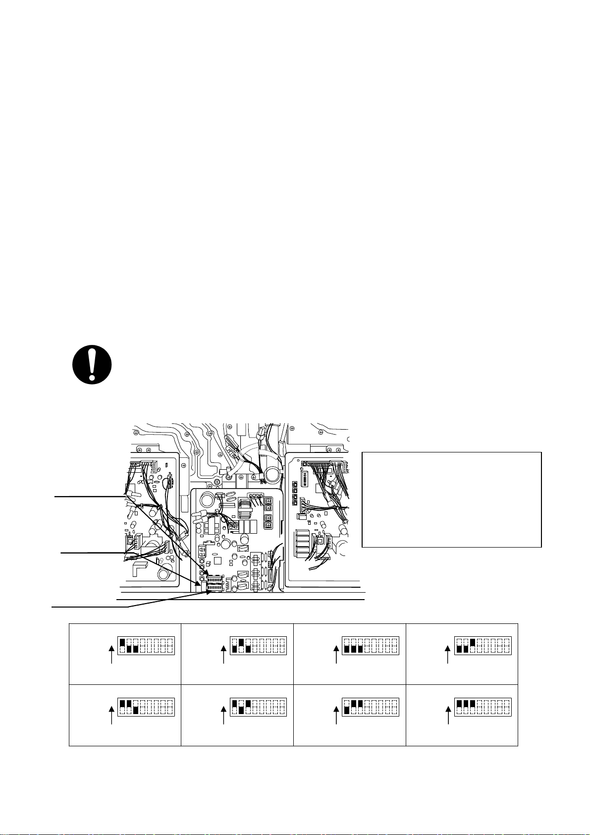
p
TEMPERATURE SETTINGS
There are 8 pres et temperatures that you can select from by changing the dipswitch settings
on the computer board.
The temperature has been preset at the factory to 120ºF (49ºC).
If you desire to change the set temperature with dipswitc hes, please refer to the diagram on
below. These temperatures are available: 100ºF, 115ºF, 120ºF, 135ºF, 145ºF, 155ºF, 165ºF,
and 185ºF.
If you desire a hot water temperature other than the 8 preset se ttings, please purchase the
optional temperature remote controller (part No. 9007603005 (TM-RE30)).
With this optional remote controller you can set the temperature from 100ºF to 185ºF with
various increments.
Please read the instructions carefull y prior to installing the remote controller, as failure to do
so could damage the temperature controller and/or the water heater, which will void the
warranty.
Turn off the power supply to the heater before changing the dipswitch
settings.
Only change the switches with the dark squ ares. The dark squares indicate
which direction the dipswitch should be set to.
DO NOT set to 185ºF if you use your water heater in a recirculation system.
This will cause damage to the heater and void the warranty.
Upper bank of
dipswitches
7-Seg LED
Lower bank of
dipswitches
Temperature Settings
100°F
(38 ºC)
145°F
(63 ºC)
1 2 3 4 5 6 7 8
O
N
MODE
TMP2
TMP1
TMP3
1 2 3 4 5 6 7 8
O
N
MODE
TMP2
TMP1
TMP3
DIRE
OUT
DIRE
OUT
P-ALARM
MST
P-ALARM
MST
115°F
(46 ºC)
155°F
(68 ºC)
1 2 3 4 5 6 7 8
O
N
TMP3
MODE
TMP2
TMP1
1 2 3 4 5 6 7 8
O
N
TMP3
MODE
TMP2
TMP1
DIRE
OUT
OUT
DIRE
P-ALARM
MST
P-ALARM
MST
<Lower bank of di
O
120°F
(49 ºC)
DEFAULT
165°F
(74 ºC)
N
O
N
To change dipswitch settings
for temperatures, locate the
lower bank of dipswitches to
the right of 7-Seg LED.
DO NOT adjust the upper bank
of dipswitches.
The dark squares indicate the direction
the dipswitches should be set to.
switches>
1 2 3 4 5 6 7 8
TMP2
OUT
TMP3
MODE
TMP1
DIRE
P-ALARM
1 2 3 4 5 6 7 8
TMP2
MODE
TMP1
P-ALARM
DIRE
OUT
TMP3
MST
MST
135°F
(57 ºC)
185°F
(85 ºC)
1 2 3 4 5 6 7 8
O
N
TMP2
MODE
TMP1
TMP3
1 2 3 4 5 6 7 8
O
N
MODE
TMP2
TMP1
TMP3
DIRE
DIRE
OUT
P-ALARM
P-ALARM
OUT
MST
MST
- 33 -
Page 34
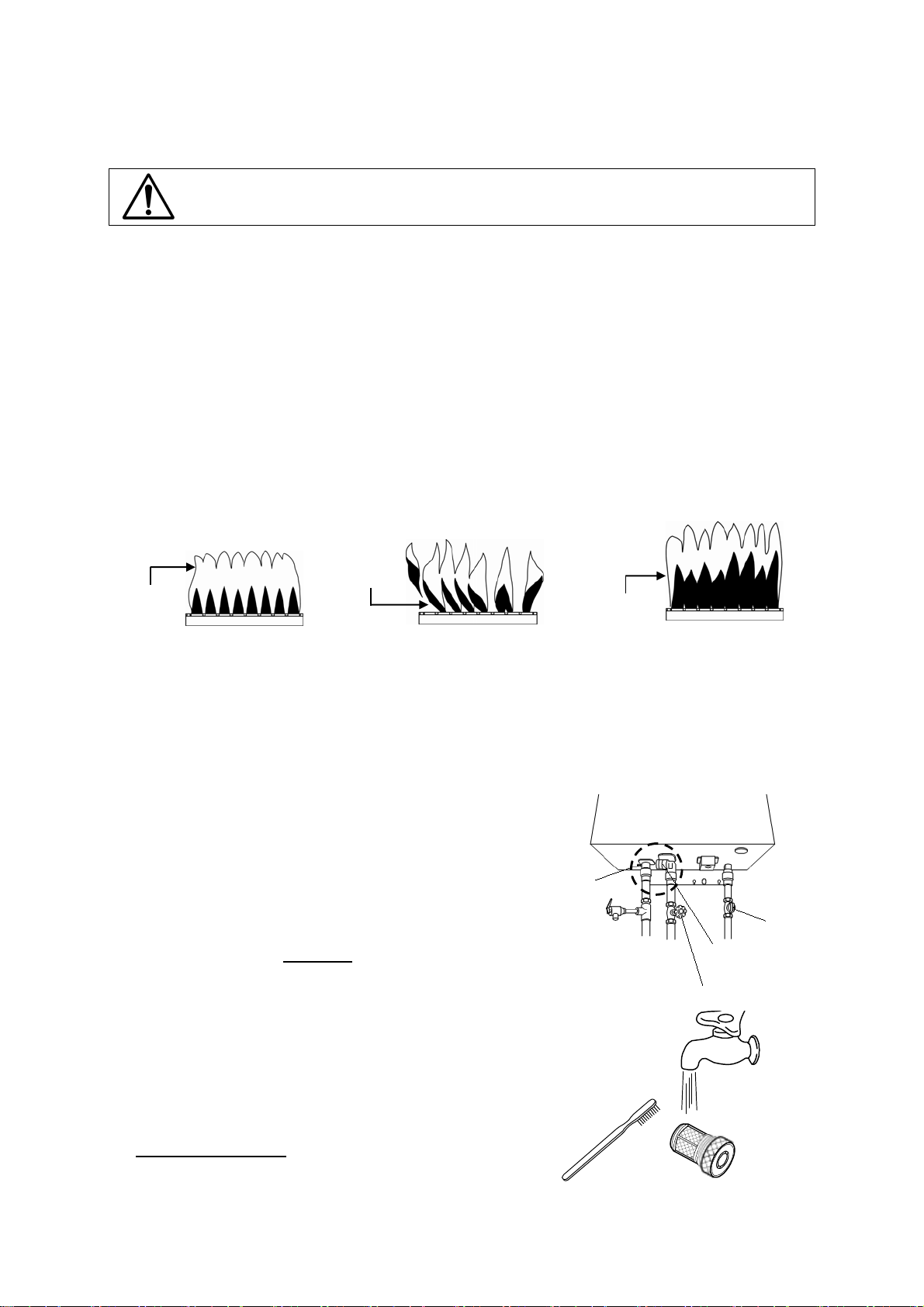
MAINTENANCE AND SERVICE
WARNING: Turn off the electrical power supply and close the manual gas
control valve and the manual water con trol val ve bef or e servi ci ng.
Clean the cold-water inlet filter. (Refer to diagram below)
Be sure that all openings for combustion and ventilation air are not blocked.
The venting system should be checked annually for any leaks, corrosion, blockages or
damage.
The burner should be checked annually for dust, lint, grease or dirt.
Keep the area around the water heater clear. Remove any combustible materials, gasoline or
any flammable vapors and liquids.
In accordance with all local codes and common safety practices, Water discharged from the
pressure relief vale can cause severe burns instantly from scalding. DO NOT touch the
pressure relief valve.
If the relief valve discharges periodically, it may be due to thermal expansion in a closed
water supply system. Contact the water supplier or local plumbing inspector on how to
correct this situation.
Visual check of burner flames (see below) through the burn er window in the burner assembly
located at the middle of the water heater.
Blue flame
Satisfactory
The manufacturer recommends having the unit checked once a year or as necessary by a
licensed technician. If repairs are needed, any repairs should be done by a licensed technician.
Flame
blowing up
Unsatisfactory
Red or Yellow
flame
Unsatisfactory
UNIT DRAINING and FILTER CLEANING
1. Close the manual gas shut off valve.
2. Turn off power to the unit, and then turn on again.
3. Wait 30 seconds, and then turn off power to the
unit, yet again.
4. Close the water shut off valve.
5. Open all hot water taps in the house. When the
residual water flow has ceased, close all hot
water taps.
6. Have a bucket or pan to catch the water from the
unit’s drain plugs. Unscrew
drain all the water out of the unit.
7. Wait a few minutes to ensure all water has
completely drained from unit.
8. Clean the filter: Check the water filter located
within the cold inlet. With a tiny brush, c lean the
water filter of any debris which may have
accumulated and reinsert the filter back into the
cold water inlet.
9. Securely screw the drain plugs back into place.
Hand- tighten only.
the drain plugs to
Drain Plug
Gas Valve
Drain Plug
with Filter
Water Valve
- 34 -
Page 35
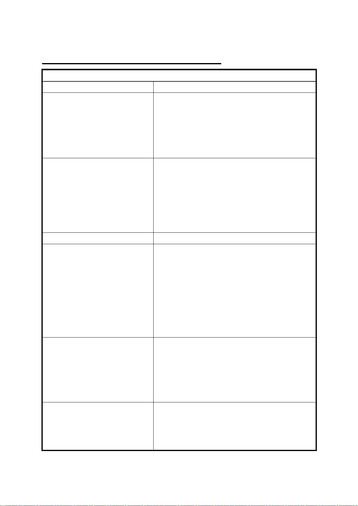
GENERAL TROUBLESHOOTING
~ TEMPERATURE and AMOUNT OF HOT WATER ~
PROBLEM POSSIBLE SOLUTIONS
It takes long time to get hot water at
the fixtures.
The time it takes to deliver hot water from the water
heater to your fixtures depends on the length of
piping between the two. The longer the distance or
the bigger the pipes, the longer it will take to get hot
water.
If you would like to receive hot water to your fixtures
quicker, you may want to consider a hot water
recirculation system. (p. 40)
The water is not hot enough.
The water is too hot.
The hot water is not available when
a fixture is opened.
Compare the flow and temperature. See the chart
on p. 51.
Check cross plumbing between cold water lines
and hot water lines.
Is the gas supply valve fully open? (p. 29)
Is the gas line sized properly? (p. 17)
Is the gas supply pressure enough? (p. 16)
Is the set temperature set too low? (p. 30,33)
Is the set temperature set too high? (p. 30,33)
Make sure the unit has 120 VAC / 60 Hz power supply.
If you are using the remote controller, is the power
button turned on? (p. 30)
Is the gas supply valve fully open? (p. 29)
Is the water supply valve fully open? (p. 29)
Is the filter on cold water inlet clean? (p. 34)
Is the hot water fixture sufficiently open to draw at
least 0.5 GPM through the water heater? (p. 30)
Is the unit frozen?
Is there enough gas in the tank / cylinder? (for Propane models)
The hot water gets cold and stays
cold.
Fluctuation in hot water temperature.
Is the flow rate enough to keep the water heater
running? (p. 30)
If there is a recirculation system installed, does the
recirculation line have enough check valves?
Is the gas supply valve fully open? (p. 29)
Is the filter on cold water inlet clean? (p. 34)
Are the fixtures clean of debris and obstructions?
Is the filter on cold water inlet clean? (p. 34)
Is the gas line sized properly? (p. 17)
Is the supply gas pressure enough? (p. 16)
Check for cross connection between cold water
lines and hot water lines.
- 35 -
Page 36
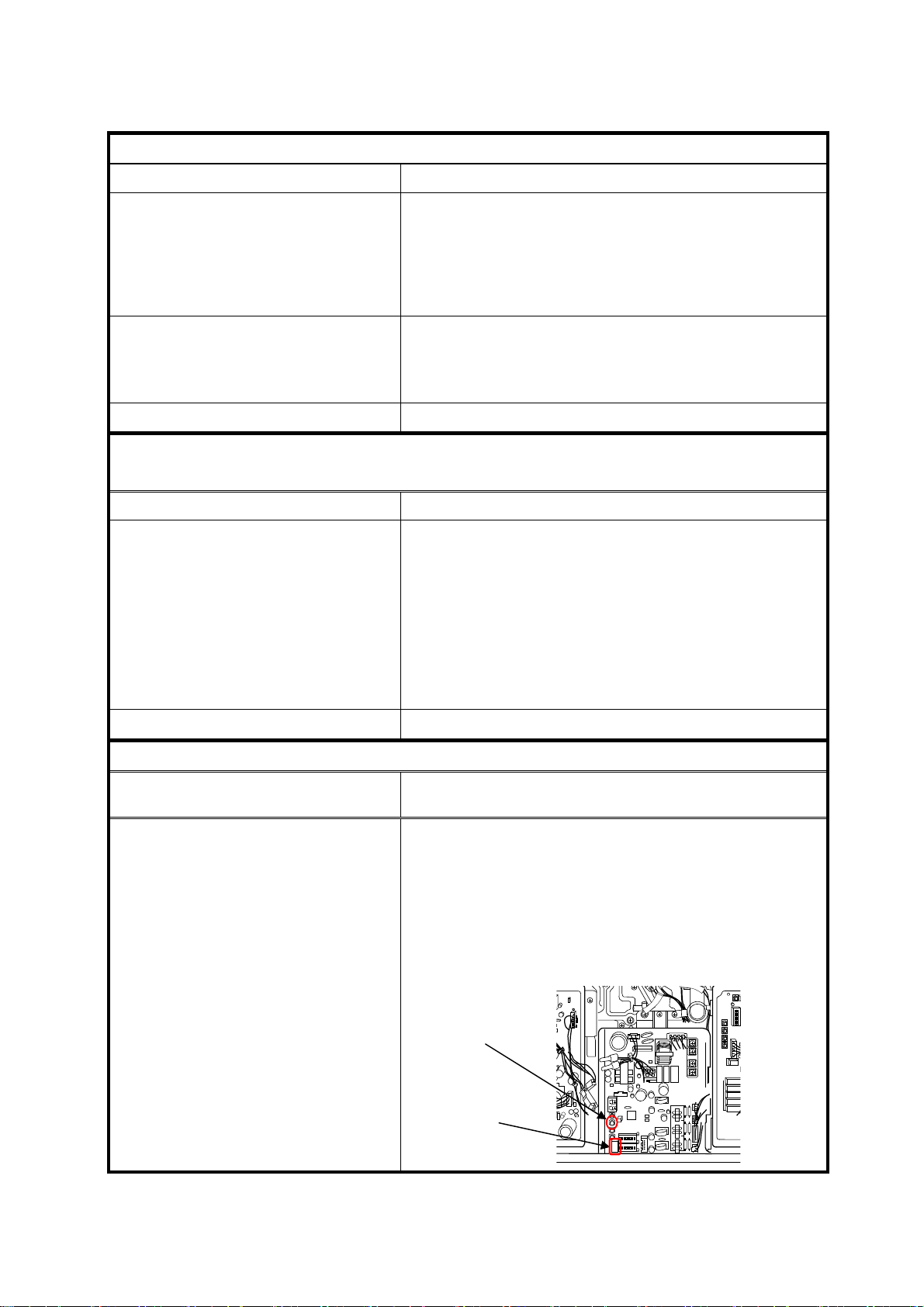
~ WATER HEATER ~
PROBLEM POSSIBLE SOLUTIONS
Unit does not ignite when water goes
through the unit.
Is the flow rate over 0.5 GPM? (p. 30)
Check for the filter on cold water inlet. (p. 34)
Check for reverse connection and cross connection.
If you use the remote controller, is the power button
turned on? (p. 30)
The fan motor is still spinning after
operation has stopped.
Abnormal sounds come from the unit.
~ REMOTE CONTROLLER: 9007606005
(TM-RE30) (OPTIONAL) ~
PROBLEM POSSIBLE SOLUTIONS
Remote controller does not display
anything when the power button is
turned on.
An ERROR code is displayed.
~ EASY-LINK SYSTEM ~
This is normal. After operation has stopped, the fan
motor keeps running for 35 seconds in order to reignite quickly, as well as push all exhaust gas out of
the flue.
Contact the manufacturer at 1-877-737-2840.
Press the ON/OFF button.
If the lamp lights up ⇒
This is normal. When the unit has not operated for
five minutes or more, the display turns off to
converse energy.
If the lamp does not light ⇒
Make sure the unit gets power supply.
Make sure the connection to the unit is correct.(p. 21)
Please see the p. 37.
PROBLEM POSSIBLE SOLUTIONS
How are the unit numbers assigned?
For an Easy-Link syste m, other than the Parent Un it
(which is always labeled #1), all the other units (the
Child units) are numbered randomly.
To check which numbers are assigned to which
units, push the button on the computer board of a
unit as shown below. The unit number will be
displayed on the 7-Seg LED.
Unit# display
button
7-Seg LED
- 36 -
Page 37
TROUBLESHOOTING – ERROR CODES
The units are self diagnostic for safety and convenience when trouble shooting.
If there is a prob lem with the installation or the unit, it will display a numerical error code on the
remote controller (if installed) or on the 7-Seg LED of the central computer board and section
computer board to communicate the source of the problem.
Consult the following chart for the cause of each error code.
Error
Code
031 Incorrect dipswitch setting 391 Air-fuel Ratio Rod failure 661
101 Warning for 991 error code 441 Flow Sensor Failure 681 Abnormal External Fan motor
111 Ignition failure 510 Abnormal Main Gas Valve 701 Computer board Fault
121 Loss of flame 551
311 Output thermistor failure 611 Fan Motor Fault 741
321 Inlet thermistor failure 631 Abnormal External Pump 761
331 Mixing thermistor failure 651
Malfunction description
Single Unit
The 7-Seg LED displays the 3-digit error codes one
digit at a time. The remote controller (if installed)
displays the whole 3-digit error code at once.
When the right and/or left combustion section has an
error code, the red lamp next to the 7-Seg LED on the
central computer board will flash to indicate which
combustion section has the error code. Refer to the
above picture.
Example
If your unit has the “321” error code (inlet thermistor),
The 7-Seg LED, will flas h the 3-digit error code one
The remote controller, however, will display “321”
:
digit at a time. The 7-Seg LED will display “3”...
“2”... “1”, and then repeat the 3 digits.
on its screen, in its entirety.
Unit #1
PARENT
“3..2..1..0..2”
“232”
Unit #2
CHILD
“3..2..1”
Remote
Controler
Unit #3
CHILD
7-Seg LED
Error
Code
Unit #4
CHILD
Malfunction description
Abnormal Gas Solenoid
Water Control Valve Fault
(Flow Adjustment function)
The top red lamp will
flash when the right
combustion section has
an error code.
The mid red lamp will
flash when the left
combustion section has
an error code.
Valve
Error
Code
721 False Flame Detection
991 Imperfect combustion
Remote controller (Optional)
Malfunction description
Water Control Valve Fault
(Bypass function)
Miscommunication between water
heater and remote controller
Miscommunication in Easy-
Link OR Multi-unit system
Easy-Link
The 7-Seg LED on the PARENT unit displays a 5-digit
number to signify which unit in the Easy-Link system
has the error, and what the error code is. The 7-Seg
LED displays the number one digit at a time.
T h e remote controller (if i nstalled) displays a 3-digit
number which also signifies which unit has the error,
and what the error code is.
The unit that has the error in an Easy-Link system will
display the error code on its 7-Seg LED in exactly the
same way as if it were only a Single Unit.
When the right and/or left combustion section has an
error code, the red lamp next to the 7-Seg LED on the
central computer board will flash to indicate which
combustion section has the error code. Refer to the
above picture.
Example:
If Unit #2 has the “321” error code (inlet thermistor),
Th e 7-Seg LED on the PARENT unit will display “3”...
The remote controller, however, will display “232” on
The 7-S eg LED on Unit #2 will dis play “3” …. “ 2”…. “1” ,
“2”… “1”… “0”… “2”, displaying only one digit at a
time. The first 3 numbers indicate the error code.
The last two numbers indicate that Unit #2 has the
error.
its screen in its entirety. The first “2” indicates that
Unit #2 has the error. The “32” indicates the first two
digits of the “321” error code.
just like in the Single Unit example.
- 37 -
Page 38
OPERATING SAFETY
FOR YOUR SAFETY READ BEFORE OPERATING
WARNING: If you do not follow these instructions exactly, a fire or explosion may
result causing property damage, personal injury or loss of life.
A. This water heater does not have a pilot. It is equipped with an ignition device that
automatically lights the burner. Do not
B. BEFORE OPERATING smell all around the water hea ter area for evidence of leaking
gas. Be sure to smell next to the floor because some gas is heavier than air and will
settle on the floor.
WHAT TO DO IF YOU SMELL GAS.
Do not try to light any appliance.
Do not touch any electric switch, do not use any phone in your building.
Immediately call your gas supplier from a neighbor's phone. Follow the gas
supplier's instructions.
If you cannot reach your gas supplier, call the fire department.
C. Use only your hand to turn the gas valve knob. Never use tools. If the knob will not
turn by hand, don't try to repair it. Call a qualified service technician. Forced or
attempted repair may result in a fire of explosion.
D. Do not use this water heater if any part has been under water. Immediately call a
qualified service technician to inspect the water h eater and to replace any damaged
parts.
try to light the burner by hand.
OPERATING INSTRUCTIONS
1. STOP! Read the safety information above or in the Owners Manual.
2. Turn off all electric power to the water heater.
3. Do not attempt to light the burner by hand.
4. Turn the manual gas valve located on the outside of the unit clockwise ↻ to the of f
position.
5. Wait five (5) minutes to clear out any gas. If you then smell gas. STOP! Follow "B" in
the safety information above on this label. If you don't smell gas, go to next step.
6. Turn the manual gas valve located on the outside of the unit counter clockwise ↺ to
the ON position.
7. Turn on all electrical power to the water heater.
8. If the water heater will not operate, follow the instructions “to Turn Off Gas to water
heater" and Call your service technician or gas supplier.
TO TURN OFF GAS TO APPLIANCE
1. Turn off all electric power to the water heater if service is to be performed.
2. Turn the manual gas v alve located on the outside of the unit clock wise ↻ to the o ff
position.
- 38 -
Page 39
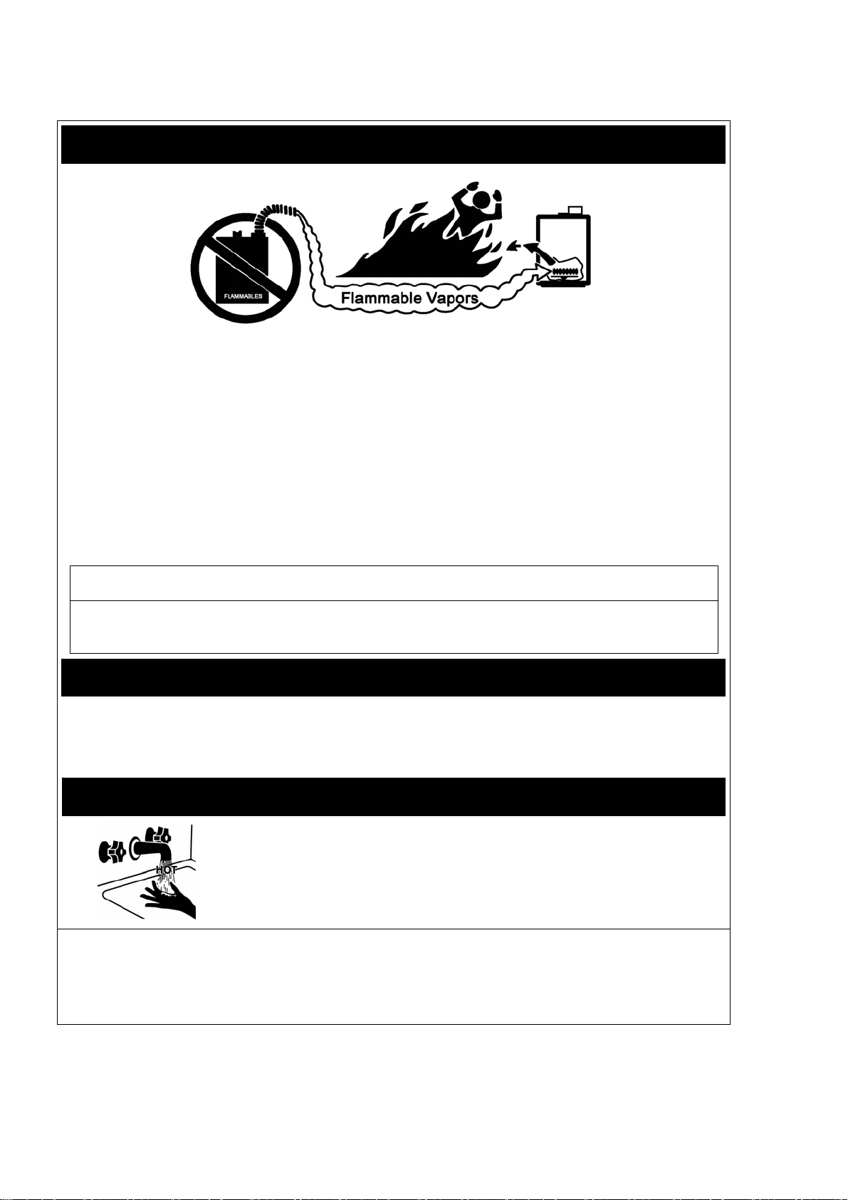
DANGER
Vapors from flammable liquids will explode and catch fire causing death or severe burns.
Do not use or store flammable products such as gasoline, solvents or adhesives in the same
room or area near the water heater.
Keep flammable products:
1. Far away from heater
2. In approved containers
3. Tightly closed
4. Out of children's reach
WARNING: Do not install water heater where flammable products will be stored.
Read and follow water heater warnings and instructions. If owner’s manual is missing,
contact the retailer or manufacturer.
Vapors:
1. Cannot be seen
2. Vapors are heavier than air
3. Go a long way on the floor
4. Can be carried from other rooms to the
main burner by air currents
WARNING
The outlet hot water temperature of the wat er heater is factory set at 120 ºF (49ºC).
Use this heater at your own risk. The set outlet water temperature can cause severe burns
instantly or death from scalds. Test the water before bathing or showering.
Do not leave children or an infirm person in the bath unsupervised.
DANGER
Hot Water Heater temperature over 125 ºF (52ºC) can cause severe
burns instantly or death from scalding. Children, disabled and elderly
are at the highest risk of being scalded. Feel water temperature before
bathing or showering. Temperature limiting valves are available. Ask a
professional person.
WARNING: California Proposition 65 lists chemical substances known to the state to cause
cancer, birth defects, death, serious illness or other reproductive harm. This product may contain
such substances, be their origin from fuel combustion (gas, oil) or components of the product
itself.
- 39 -
Page 40
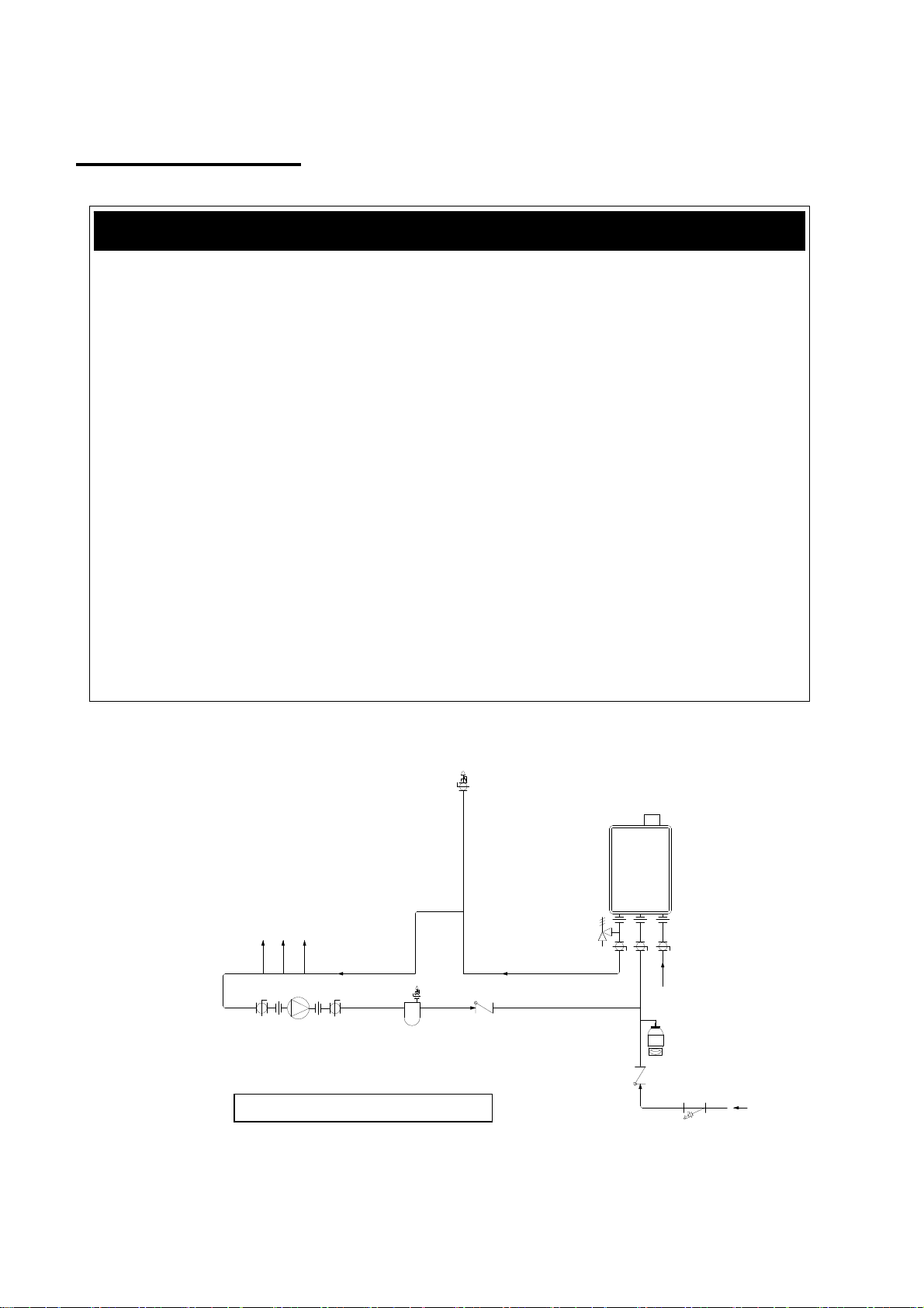
p
pump
APPLICATIONS
In order to purge air in water pipes within a closed-loop system, an air vent and
air separator should be installed in to the system. Required circulation flow rates
are labeled next to each application diagram. These flow rate requirements must
be followed.
Toxic chemicals used in boiler treatments such as alcohol, glycerol and glycol groups
must not be introduced into the system i f the system incorporates an o pen-loop potable
water system.
Toxic chemicals used in boiler treatments such as alcohol, glycerol and glycol group
must not be introduced into the system when used for open loop potable water and
space heating.
The w ater heater can be used to supply po table water and space heating and shall not
be connected to any heating system or component(s) previously used with non-potab le
water where any chemicals were added to the water heating appliances.
When the system requires water for s pace heating at temperatures high er than required
for other uses, a means such as a mixing valve shall be installed to temper the water for
those other uses in order to reduce scald hazard potential.
Water temperature over 125 F (52ºC) can cause severe burns instantly or death from
scalds.
Chemicals such as diluted Glycol can be used for radiant floor, Hydro/fan coil air or
Baseboard heating only. The diluted solution of glycol must contain between 25 and
55% of Glycol. Be aware that in closed-loop glycol systems, low pressure in the heat
exchanger can cause low-temperature boiling, resulting in excessive noise and damage
to the water heater. Consult with the glycol maker for specifications prior to use.
Space Heating Applications
WARNING
*Therecirculationpumpistobecontrolledby:
‐Dual‐setaquastat(recommendedw/timer)
OR
‐“PumpControlConnections”.Refertop.22.
*Therecirculationpumpistoprovidenoless
than2GPMandnomorethan4GPMthrough
eachactivatedunitinthesystem.
Hotwateroutletto
fixtures
Recirculation
This is a concept drawing only.
Re-circulation:
AirVent
S
Air
se
arator
Checkvalve
Checkvalve
Hot
Water
Outlet
Cold
Gas
Water
Inlet
Inlet
Gassupply
Expansiontank
Unions
Ballvalves
Coldwater
inlet
Y‐Strainer
- 40 -
Page 41
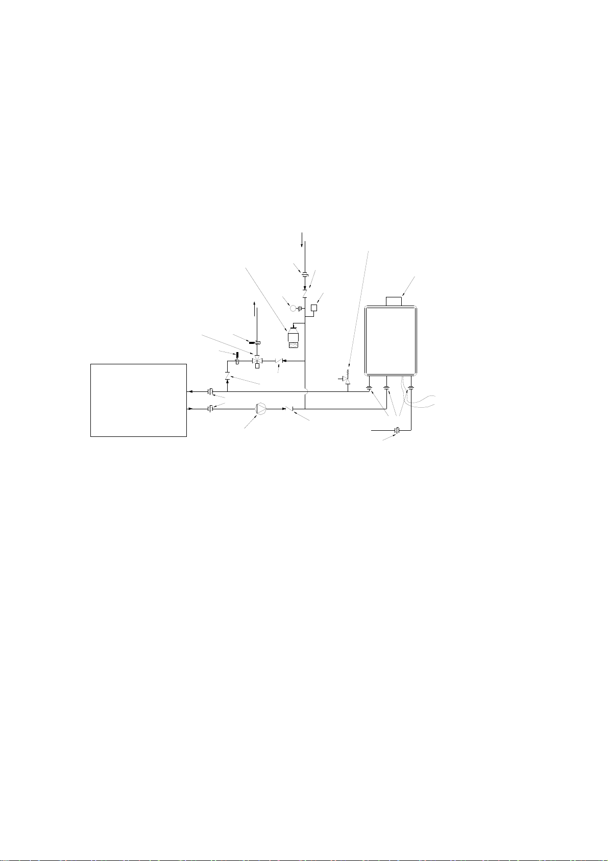
Dual-purpose hot water heating (Domestic and Space Heating):
Diagramatic Layout of Radiant Heating and
Domestic Water Heater Per Mass. Code
An approved Pressure Only
An approved Pressure Only Relied
Thermostatic Mixing Valve
Heating Coil
(used with air-handler)
**Maximum allowable distance of
50-Ft. from water heater and
heating panel
Apply Correct
Thermal
Expansion
Tank-Size Per
Application
Thermometer
Tempered
Water To
House
Thermometer
T
Shut-Off
Valves
Pump (Must Be Sized Properly
With Each Application). Pump
Shall Run 60 Seconds Every 6
Hours
Shut-Off
Valve
Pressure
Gauge
Check
Valves
Cold Inlet
P
Check Valve Will
Have 1/8" Hole in
Check, As Per
Mass. Code
Atmospheric
Vacuum Breaker
Check Valve
Relief Valve, Tie to Location
Valve, Tie to Location approved By
approved by Local Codes and
Local Codes and Must Meet BTU
Must Meet BTU Rating of Takagi
Rating of water heater Model Used
Model Used
5" Gas Exhaust Vent (Discharge
Must Comply with Local and
State Codes). Can Not Be
Common Vented with Other
Appliances
Takagi
Hot
Cold
Gas
Water
Water
Outlet
Drain
Plug
T-Handle Gas
Shut-Off Valve
Inlet
Water
Filter
Inlet
Unions
120 VAC Switch or Outlet
*Thecirculationpumpistoprovideno lessthan 2GPMandnomorethan4 GPMthrough eachactivated
unitinthesystem.
Priority Control Devices such as a flow switch, an Aquastat or other electronic controller can be used to
prioritize the domestic water system over the heating system.
Warning: Follow all local codes, or in the absence of local codes, follow the most recent edition of the
National Standard Code, ANSI Z21. 10.3.
Warning: This illustration is a concept design only. The reference to the 1/8
th
hole in check is only for
the State of Massachusetts. There are a wide variety of variations to the application of controls and
equipment presented. Designers must add all necessary safety and auxiliary equipment to conform to
code requirements and design practice. For more details, contact the manufacturer.
- 41 -
Page 42
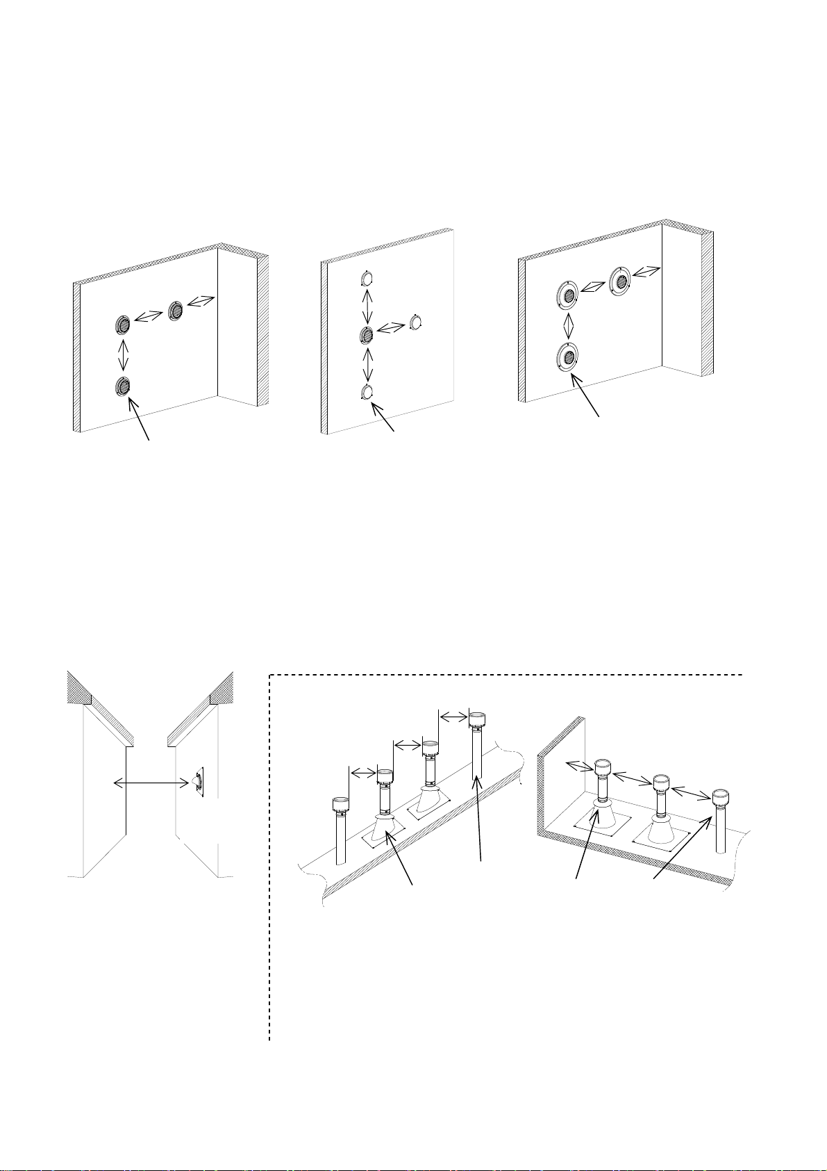
ADDITIONAL CLEARANCES
y
Please follow all local and national codes in regards to proper termination clearances. In the absence of
such codes, the following clearances can be used as guidelines. Local codes supersede these
guidelines.
For sidewall terminations
2ft.
1ft.
1ft.
Inside
corner
Exhaust termination
For multiple sidewall exhaust
terminations (e.g. multi-unit
systems), an exhaust termination
must be at least 1 ft. away from
another exhaust termination. An
exhaust termination must also be
at least 2 ft. away from an inside
corner (if the adjacent wall is less
than 2 ft. of length, the minimum
required distance aw ay from the
inside corner will be equal to the
length of the wall).
2ft.
3ft.
3ft.
3ft.
Air supply inlet
For Direct-Vent sidewall
terminations that use two
separate penetrations for the
intake and exhaust, distance
the intake and exhaust
terminations at least 3 ft. away
from each other, no matter the
orientation.
For multiple-unit, direct-vent
sidewall terminations that combine
the intake and exhaust into a single
penetration, space each direct-vent
termination at least 1 ft. away from
each other, no matter the
orientation. A direct-vent
termination must also be at least 2
ft. away from an inside corner (if the
adjacent wall is less than 2 ft. of
length, the minimum required
distance away from the inside
corner will be equal to the length of
the wall).
1ft.
1ft.
Inside
corner
Direct-Vent termination
2ft.
Exhaust
termination
Exhaust and/or Direct-Vent
sidewall terminations should
be at least 2 ft. away from an
opposite surface/wall. Do not
place the termination directly
in front of an opening into a
building.
For rooftop terminations
A
Air intake
2ft.
Exhaust
termination
A
A
Air intake
A
A
Exhaust termination
A: in accordance with local codes
For multiple-unit rooftop terminations (whether for standard indoor or DirectVent installations) space all exhaust and intake terminations in accordance
with local codes. An exhaust termination must be spaced from a wall or
surface in accordance with local codes as well. In the absence of such a
code, an exhaust termination must be a horizontal distance of at least 2 ft.
from a wall or surface.
awa
- 42 -
Page 43
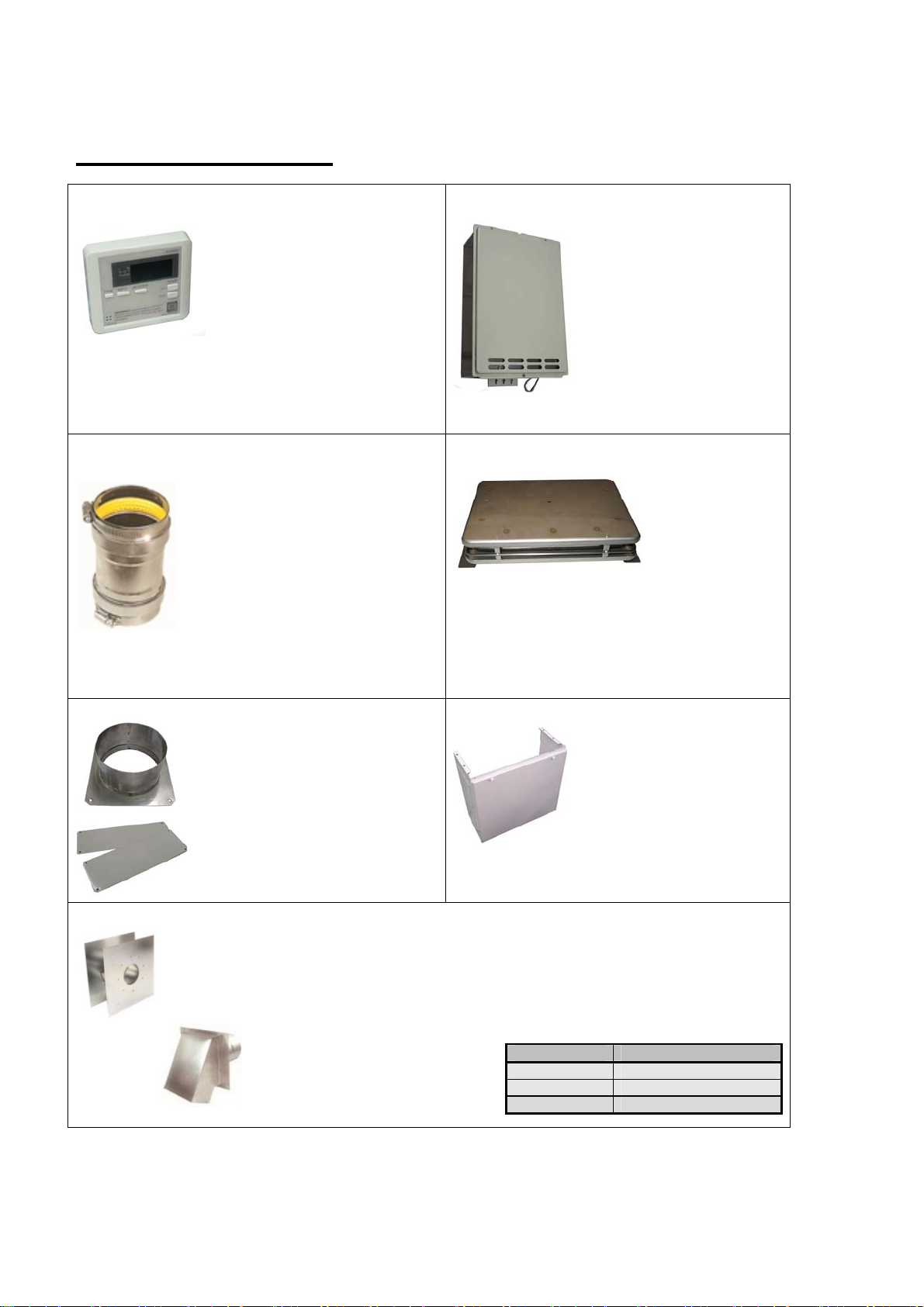
OPTIONAL ITEMS
p
1. Temperature remote controller: 9007603005
(TM-RE30)
The temperature remote
controller has two functions. It
allows the output temperature
from the water heater to be
adjusted within the range of
100 °F to 185 °F, and it also
works as a diagnostic tool that
whenever there is a problem with the unit. The
temperature options are 100 °F, 105 °F, 110 °F,
115 °F, 120 °F, 125 °F, 130 °F, 135 °F, 140 °F,
145 °F, 150 °F, 155 °F, 160 °F, 165 °F, 170 °F,
175 °F, 180 °F and 185 °F. See the troubleshooting
section for information on
3. 5” Backflow preventer and F-F adaptor:
9008202005
the exhaust system. Install this adaptor in accordance
with the installation instructions that are packaged
with the adaptor and any applicable codes.
5. Direct-vent conversion kit: 9007669005
will give a concise error code
ossible error codes.
There are two functions available for
this adaptor which can be connected
with the water heater and NovaVent
venting line and prevents the
backflow of air through the exhaust
vent. This helps prevent harmful
exhaust gases from entering the
home, as well as helping to prevent
the unit from freezing in areas where
cold air can be blown or drawn into
(TM-DV50)
This kit can be used to convert the
910 (T-M50) from a conventional
vent system to a direct-vent (or
sealed combustion) system. This is
a CSA tested conversion kit. Install
this conversion kit in accordance
with the manufacturer’s installation
instructions and any applicable
codes.
2. Multi-unit controller: 9007675005
(TM-MC01)
The multi-unit controller can
control a maximum of 10
water heaters, from 15,000
BTU to 3,800,000 BTU. It
also works as a diagnostic
tool that will give a concise
error code whenever there
is a problem with the unit.
Usage of this controller
requires having the
9007603005 (TM-RE30)
remote controller.
4. Vent cap: 9007677005 (TM-VC50)
The vent cap is for
outdoor installation
with the 910 (TM50) water heater.
The cap is
installed on the top
of the unit, instead
of connecting an
exhaust vent pipe. The cap will prevent any
debris that might be in the environment from
entering the unit and causing damage or a fire
hazard, as well as preventing rain or other
weather from entering the unit.
6. Pipe cover: 9007673005 (TM-PC50)
The pipe cover protects the
plumbing pipes to the 910
(T-M50) from unexpected
adjustments. This pipe cover
is fixed to the bottom of the
water heater, which hides the
plumbing and improves the
visual aspects of the whole
installation for the water heater.
7. Sidewall vent terminator (Hood) and Wall thimble:
They are used when venting out through the wall. These terminations are
special stainless steel vents for gas applications a nd are UL listed a s
Categoly ll, lll and lV. Fo r diff er ent wa ll thickness , there are two ran ges of
Wall Thimble
Terminator Hood
lengths available. (Refer to the NovaVent brochure for details.) Install these
vent terminations in accordance
with their installation instructions
and any applicable local codes.
- 43 -
Part # Covering wall thickness
9008347005 Wall Thimble 4 ”-7”
9008348005 Wall Thimble 5 ”-10”
9008197005 Terminator Hood
Page 44
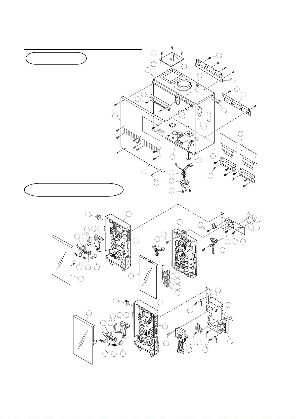
COMPONENTS DIAGRAM
Case assembly
4
11
3
12
1
10
3
3
4
2
4
2
3
5
Computer board assembly
The 910 (T-M50) and the 910 ASME (T-M50
ASME) models share the same components.
701
715
418 703
707 706
708
709
715
704
709
418 703
416705
704
707 706
710
719
718
3
13
708
6
7
3
702
113
712
713
711
714
701
113
719
8
9
4
113
113 113 716
711
717
723
708
113
416705
- 44 -
721 714
720
113
722
Page 45
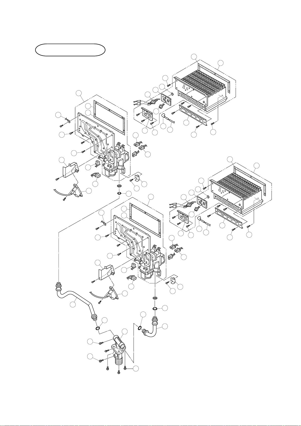
Burner assembly
The 910 (T-M50) and the 910 ASME (T-M50 ASME)
models share the same components.
705
114
115
116
113
103
109
707
112
108
104
107
106
113
111
105
110
113
101
113
117
113
707
102
707
113
117
705
113
115
116
707
102
121
707
119
118
707
114
707
119
118
109
103
707
108
112
104
107
106
113
111
105
110
113
101
113
121
126
125
123
124
120
123
122
3
- 45 -
Page 46

Combustion and Exhaust assembly
Other than Part# 444, Part# 445, Part# 446 and Part# 447, the
910 (T-M50) and the 910 ASME (T-M50 ASME) models share
the same components.
910 ASME
T-M50 ASME
(T-M50 ASME)
444
127
130
129
137
446
447
137
405
135
404
406
403
446
136
407
402
445
401
133
113
405
404
406
131
403
128
407
402
401
133
134
417
132
3
417
408
409
410
412
113
411
413
415
414
113
139
138
- 46 -
408
409
410
412
416
113
411
413
415
414
113
416
139
138
Page 47
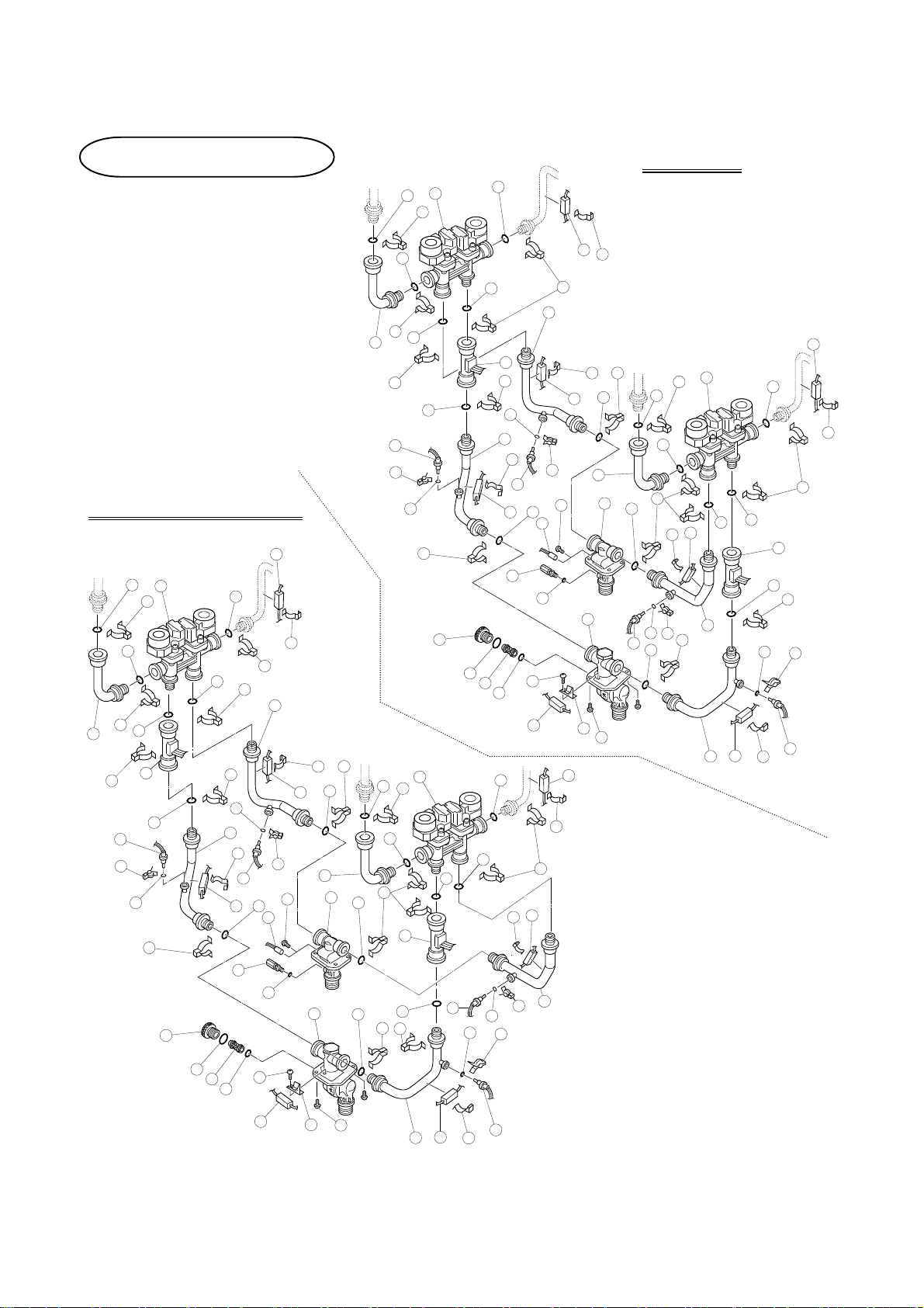
Water way assembly
910 (T-M50)
418
411
419
411
910 ASME (T-M50 ASME)
411
422
419
418
419
411
419
420
421
411
424
406
407
419
435
411
419
411
419
419
407
448
427
430
411425
441
442
443
426
411
420
428
419
411
422
421
419
411
424
406
426
427
449
427
419
411
425
406
422
439
440
411
434
411
407
419
435
418
411
419
411
419
419
419
420
421
411
430
419
407
423
427
406
430
411425
441
442
443
436
437
411
407
113
438
425
411
419
425
429
450
406
407
406
427
419
426
427
419
411
425
422
439
440
434
433
3
426
427
411
419
411
407
430
411
418
419
411
411
425
429
431
406
419
432
411
427
419
420
421
411
419
407
406
425
424
429
436
113
437
438
425
433
3
425
451
424
429
- 47 -
Page 48
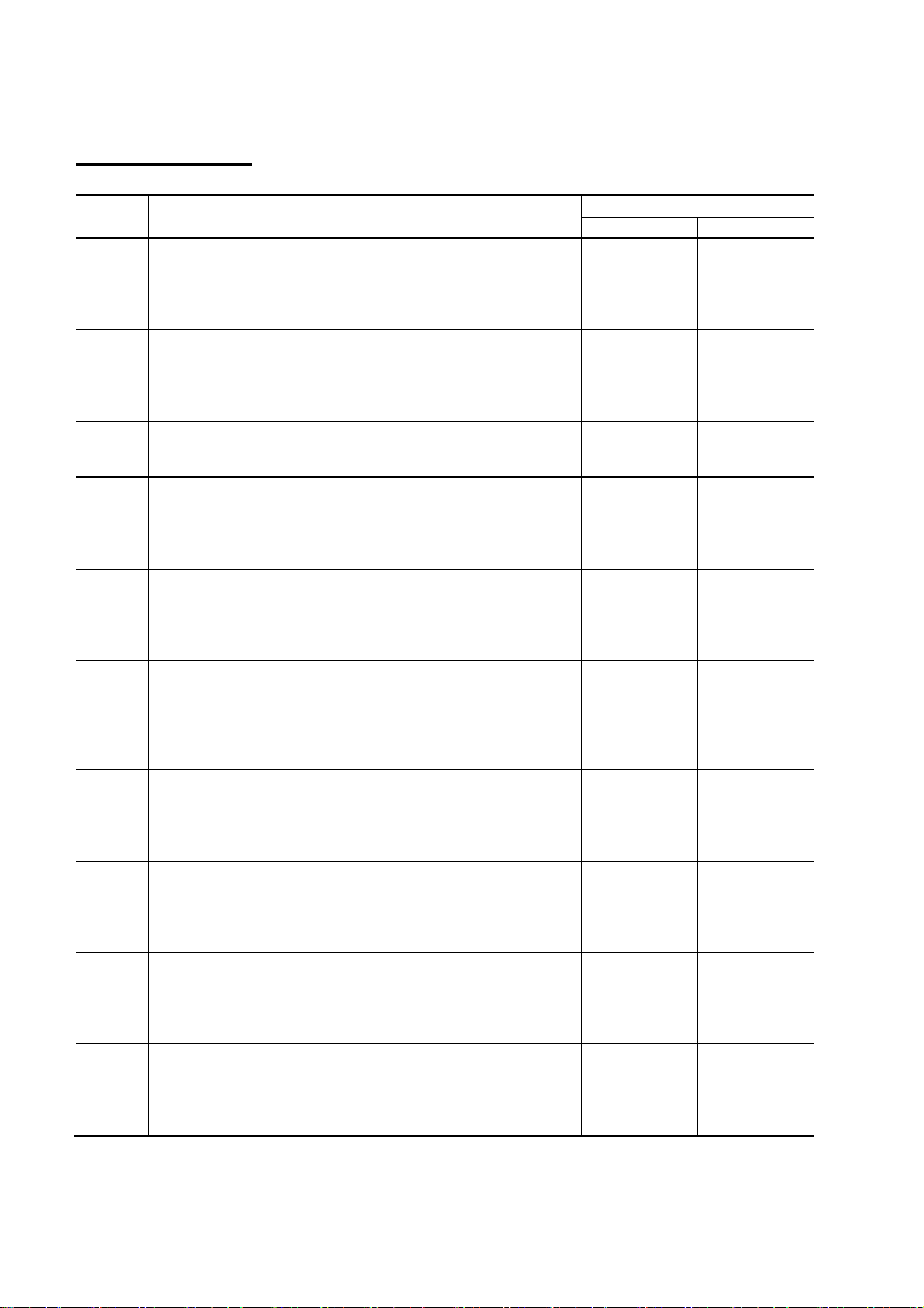
PARTS LIST
Item# Description
001
002
003
004
005
006
007
008
009
010
011
012
013
101
102
103
104
105
106
107
108
109
110
111
112
113
114
115
116
117
118
119
120
121
122
123
124
125
126
127
128
129
130
131
132
133
134
135
Manifold assembly with gas valve assembly LP
Manifold assembly with gas valve assembly NA
Case assembly
Brackets
Screw M4X10 (w/was he r)
Screw M4X10 (Coated )
Back guard panel
Power supply code assembly
Junction box
Chamber fixing plate
Rubber bush
Exhaust fixing plate
Front cover
Air blockage plate
Screw M4X12 (w/was he r)
Burner assembly
Igniter
Flame rod
Igniter rod
Damper
Rod cap
Burner window
Rod holder gasket
Rod holder
Burner holder gasket
High voltage igniter cable
Pan screw M4X8
Screw M4X10
Manifold gasket A
Manifold gasket B
Igniter plate
Gas connection plate
Pan screw M4X10
O-ring P20 NBR (Black)
Gas pipe left
Gas pipe right
O-ring P18 NBR (Black)
Gas inlet
Hex head screw M4x8
Pan screw M4X6 (w/washer)
Exhaust connecter
Exhaust combining box
Silicon ring
Exhaust gasket A
Exhaust gasket B
Case beam
Exhaust auxiliary plate
Duct
Duct cover
Part#
910 models T-M50 models
319143-265
319143-012
319143-325
319143-026
319143-237
319143-277
319143-014
319143-230
319143-334
319143-236
319143-262
319143-246
319143-025
319143-308
319143-052
319143-035
319143-037
319143-192
319143-038
319143-033
319143-034
319143-036
319143-032
319143-039
319143-059
319143-060
319143-263
319143-264
319143-044
319143-045
319143-051
319143-337
319143-062
319143-057
319143-257
319143-253
319143-350
319143-250
319143-063
319143-090
319143-261
319143-276
319143-206
319143-238
319143-239
319143-249
319143-275
319143-260
319143-258
EM305
EM335
EW001
EW002
EM264
EM333
EKJ64
EM255
EX00B
EM263
EM301
EM278
EW000
EM445
EKN74
EKK0E
EKK0F
EKK1P
EKN61
EKK2V
EKK2W
EKK32
EKK0G
EKK2M
EW00D
EW003
EM302
EM303
EKK2Y
EKK2K
EKK1B
EX00J
EW006
EK042
EM293
EM289
EZP18
EM284
EW005
EW00L
EM300
EM331
EKK3G
EM266
EM267
EM282
EM330
EM299
EM294
- 48 -
Page 49
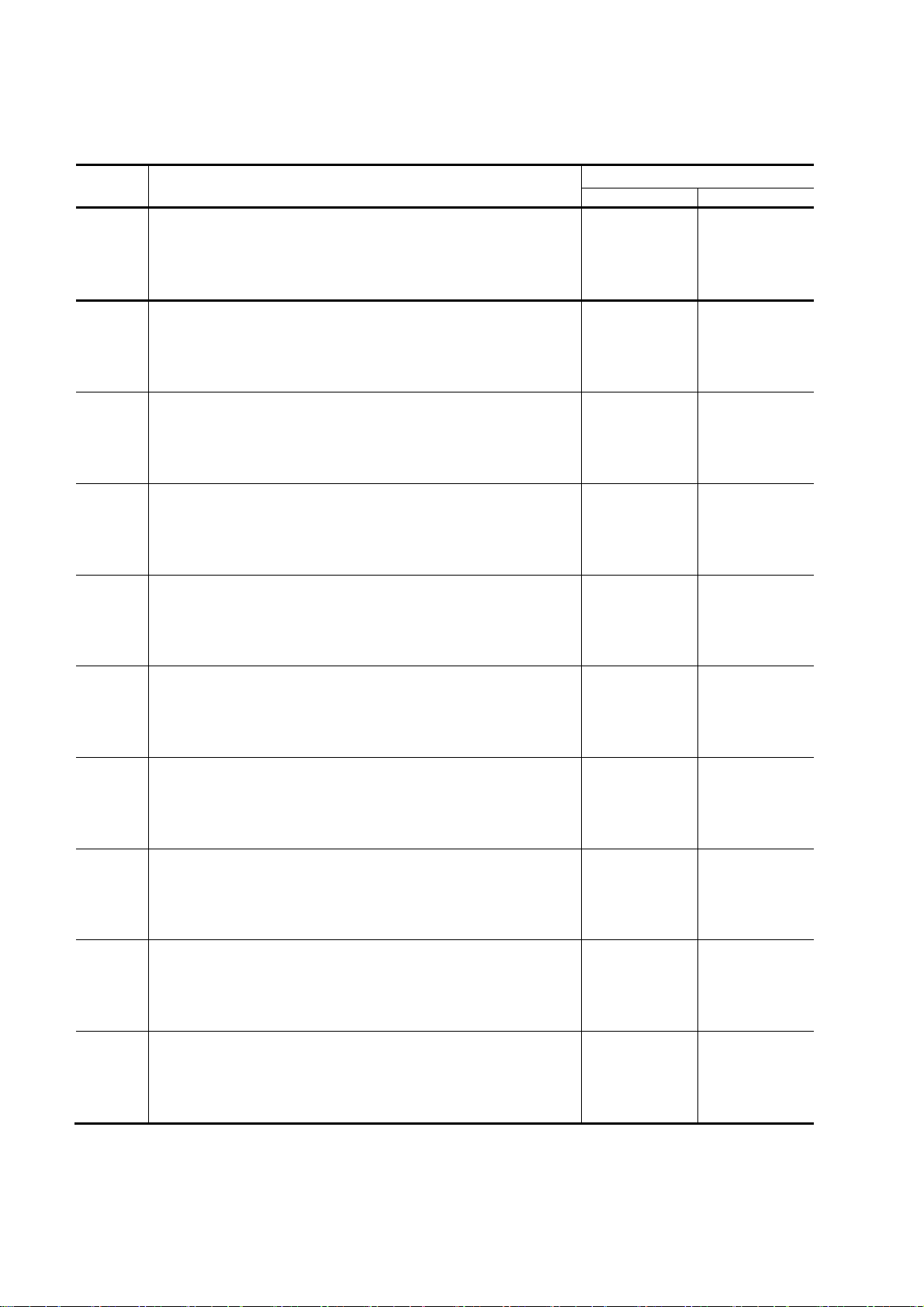
Item# Description
136
137
138
139
140
401
Freeze protection thermostat
Heat exchanger assembly for 910 (T-M50)
402
403
404
405
406
407
408
409
411
412
Pan Screw M4X12 (w/washer)
413
414
415
416
417
418
419
420
421
422
423
Left cold pipe for 910 (T-M50)
424
425
426
427
428
Left hot pipe for 910 (T-M50)
429
430
431
432
Right hot pipe for 910 (T-M50)
Right cold pipe for 910 (T-M50)
433
434
435
436
437
438
439
440
441
442
443
444
445
Heat exchanger assembly for 910 ASME (T-M50 ASME)
Connection pipe for 910 ASME (T-M50 ASME)
446
Duct gasket
Screw M4X10
Fan damper
Screw M3X6
Overheat-cut-off-fuse
Hi-limit switch
Screw M3X6
Output thermistor
Fastener "4-11"
O-ring P4 FKM
Pipe heater 122
Heater fixing plate
O-ring P16 FKM
Fan motor fixing plate
Pressure port
Urethane tube
Fan motor
Fuse fixing plate 18
Water control valve
Fastener "16AG"
O-ring P16 FKM
Flow sensor
Connecting pipe
Inlet thermistor
Heater 502
Heater 101
Heater fixing plate 16
Heater fixing plate 20
Mixing thermistor
Heater plate
Water inlet
Filter plug
O-ring P25 FKM
Water inlet filter
O-ring JASO#1021 FKM
Water outlet
Screw M4X6
Heater 117
Outlet drain plug
O-ring P6 FKM
O-ring P18 FKM
Part#
910 models T-M50 models
319143-240
319143-060
319143-147
319143-330
319143-252
319143-268
319143-149
319143-095
319143-087
319143-096
319143-097
319143-082
319143-224
319143-088
319143-083
319143-061
319143-229
319143-042
319143-344
319143-043
319143-066
319143-086
319143-077
319143-083
319143-092
319143-251
319143-254
319143-085
319143-333
319143-068
319143-125
319143-273
319143-124
319143-190
319143-256
319143-255
319143-076
319143-259
319143-070
319143-071
319143-072
319143-073
319143-269
319143-328
319143-223
319143-199
319143-080
319143-270
319143-271
319143-349
EM268
EW003
EK270
EW00B
EM286
EM308
EK333
EKN34
EW00A
EKK2T
EKH30
EZM04
EKN86
EKK27
EZM16
EW00H
EM252
EKK2D
EX019
EKK25
EKK26
EKH32
EX01H
EZM16
EKH33
EM285
EM290
EKK38
EX001
EX002
EK031
EM328
EKH38
EKK1A
EM292
EM291
EX021
EM295
EM222
EZM25
EX006
EZN21
EM309
EW009
EKN67
EKK2E
EZM06
EM323
EM326
EZM18
- 49 -
Page 50

Item# Description
447
448
449
450
451
701
702
703
704
705
706
707
708
709
710
711
712
713
714
715
716
717
718
719
720
721
722
723
Connecting pipe for 910 ASME (T-M50 ASME)
Left cold pipe for 910 ASME (T-M50 ASME)
Left hot pipe for 910 ASME (T-M50 ASME)
Right hot pipe for 910 ASME (T-M50 ASME)
Right cold pipe for 910 ASME (T-M50 ASME)
Right and left computer board
Central computer board
PV-FS wire
Thermistor connecting wire
Flame rod wire
Igniter wire
Gas valve wire
AC100V wire
Right and left computer board cover
Central computer board cover
Multi communication wire
Left communication wire
Right communication wire
Remote controller terminal
Wire Cramp
Left PCB fixing plate
Right PCB fixing plate
Transformer
Screw M4X12
Ground fault circuit interrupter
Screw M3X12
Surge box
Surge connecting wire
Part#
910 models T-M50 models
319143-278
319143-310
319143-313
319143-312
319143-311
319143-266
319143-267
319143-232
319143-233
319143-243
319143-231
319143-248
319143-245
319143-183
319143-274
319143-247
319143-234
319143-235
319143-244
319143-048
319143-241
319143-242
319143-127
319143-343
319143-227
319143-331
319143-284
319143-215
EM370
EM456
EM459
EM458
EM457
EM306
EM307
EM258
EM260
EM271
EM257
EM280
EM277
EKH43
EM329
EM279
EM261
EM262
EM273
EM167
EM269
EM270
EM296
EX013
EM207
EW01A
EM385
EKK4U
- 50 -
Page 51
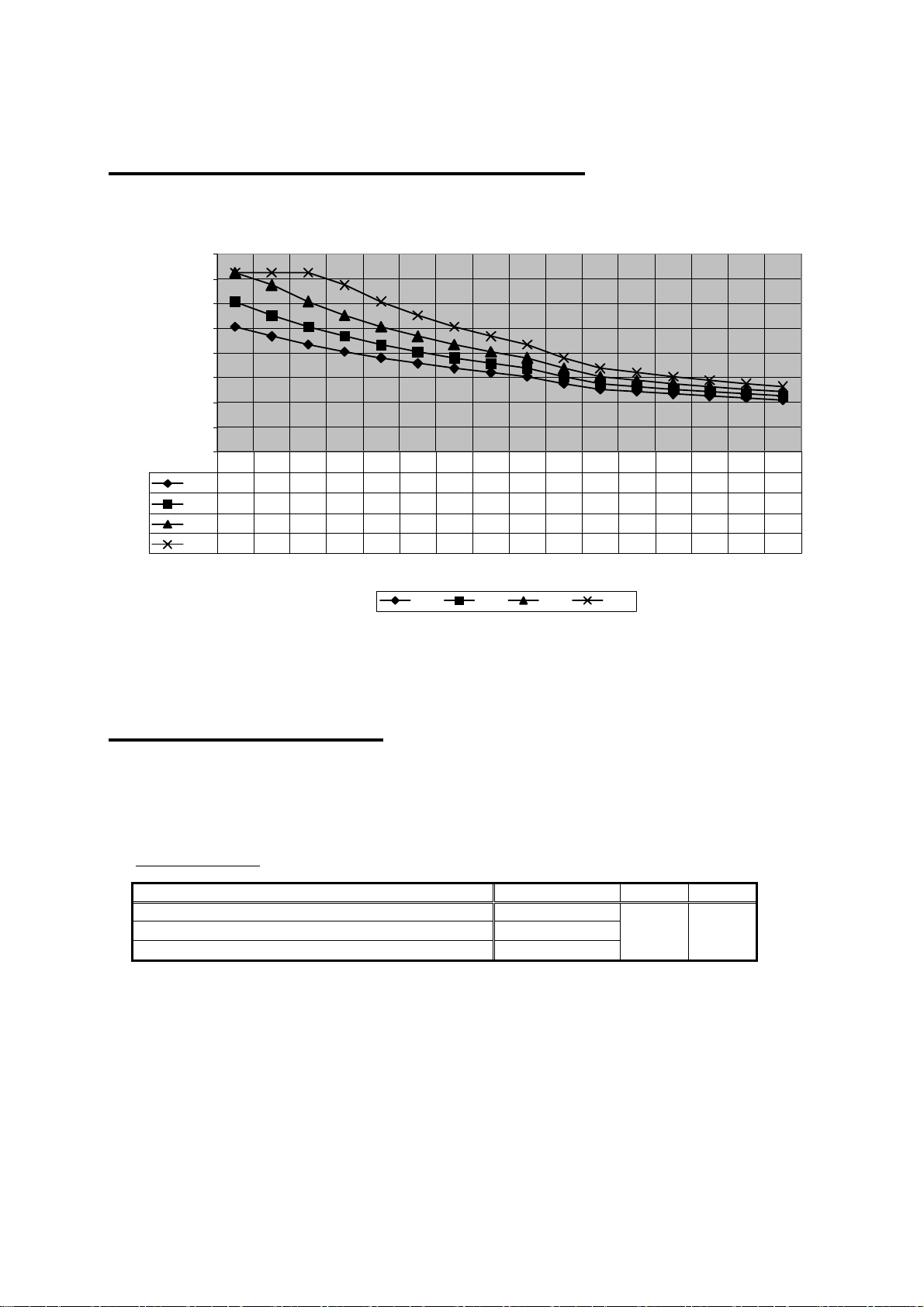
OUTPUT TEMPERATURE CHART
Chart is based on properly sized gas line
Output Temperature vs . GPM (M ax. 14 .5 GPM ) with V arious Ground Wa ter Temperatu re
16.0
14.0
12.0
10.0
8.0
6.0
Outpu t Ho t Water GPM
4.0
2.0
0.0
100 105 110 115 120 125 130 135 140 150 160 165 170 175 180 185
10.1 9.3 8.7 8.1 7.6 7.1 6.7 6.4 6.1 5.5 5.1 4.9 4.7 4.5 4.3 4.2
40 F
12.1 11.0 10.1 9.3 8.7 8.1 7.6 7 .1 6.7 6.1 5.5 5.3 5 .1 4.9 4.7 4.5
50 F
14.5 13.5 12.1 11.0 10.1 9.3 8.7 8.1 7.6 6.7 6.1 5.8 5 .5 5.3 5.1 4.9
60 F
14.5 14.5 14.5 13.5 12.1 11.0 10.1 9.3 8.7 7.6 6.7 6.4 6.1 5.8 5.5 5.3
70 F
Output Hot Water Temperature
40 F 50 F 60 F 70 F
*When the set temperature is 150 ºF or higher, maximum flow rate is limited to 10.6 GPM.
LIMITED WARRANTY
1. The manufacturer warrants this product against defects in materials or workmanship as described in this document if installed
within the United States or Canada. The manufacturer or its authorized Service Representative will, at its sole discretion,
repair or replace any failed or defective mechanical or electrical parts, or components thereof, or, if the manufacturer or its
authorized Service Representative cannot replace said parts, and repair is not commercially practicable, the manufacturer or its
authorized Service Representative will refund the purchase price. The manufacturer or its authorized Service Representative
may, at its sole discretion, use new, refurbished or reconditioned parts.
2. Warranty for all models
Commercial or Multi-Family Domestic Hot Water
(1) Limited Labor Coverage
The manufacturer will provide for reasonable labor charges associated with warranty repairs or
Warranty service must be performed by an authorized Service Representative. A list of authorized Service
All warranty claims and warranty service must be authorized and approved by the manufacturer.
(2) Includes recirculation and storage tank applications with proper circulation pump control (e.g. aquastat and/or
timer).
- Lack of a proper pump control will reduce the heat exchanger and parts warranty to 3 years
(3) In all applications, the total of length of operation time must be less than 9,000 hours for the 910 (T-M50) and 910
(T-M50) ASME models.
(4) Includes dual-purpose applications (combination heating and domestic).
:
Application Type Heat Exchanger
Single Family Domestic Hot Water
Heating
replacements within one (1) year from the date of purchase. The manufacturer will only pay directly to the
service provider.
Representatives is available upon request.
15
10
10
(2)(3)
(2)(3)
(3)(4)
Parts
5 1
[Unit: Year]
(1)
Labor
- 51 -
Page 52

3. General terms of limited warranty:
This limited warranty gives you specific legal rights, and you may also have other rights which vary from State to State. The
manufacturer will honor the warranty to the original retail buyer at the original location only, within the United States or Canada,
and it is not transferable.
THIS WARRANTY COVERS ONLY FAILED MECH ANICAL AND ELECTRICAL PARTS DUE TO FACTORY
DEFECTS UNDER NORMAL USAGE FOR THE PRODUCT’S INTENDED PURPOSES AND WITHIN THE
APPLICABLE PERIOD SPECIFIED IN THE FOLLOWI NG TABLES. ONLY DIRECT DAMAGES SHALL BE
RECOVERABLE BY A CLAIMANT UNDER THIS LIMITED W ARRANTY AND, IN NO EVENT, WHETHER AS
A RESULT OF BREACH OF CONTRACT, BREACH OF WARRANTY, TORT LIABILITY (INCLUDING
NEGLIGENCE), STRICT LIABILITY, INDE MNITY OR OTHERW ISE WILL T HE MANUFACTURER BE LIABLE
FOR ANY SPECIAL, INCIDENTAL, OR INDIRECT CO NSEQUENTIAL DAMAGES INCLUDING PROPERTY
DAMAGE, PERSONAL DAMAGES, LOSS OF USE, OR INCONVENIENCE. SOME STATES DO NOT
ALLOW THE EXCLUSION OR LIMITATION OF INCIDENTAL OR CONSEQUENTIAL DAMAGES, SO THE
ABOVE LIMITATION MAY NOT APPLY TO YOU.
4. Limitation on Duration of Implied Warranties:
ANY IMPLIED WARRANTIES ARISING UNDER STATE LAW, INCL UDI NG THE IMPLIED WARRANTIES OF
FITNESS FOR A PARTICULAR PURPOSE AND MERCHANTABILITY, SHALL IN NO EVENT EXTEND PAST
THE EXPIRATION OF ANY WARRANTY PERIOD HEREUNDER. SOME STATES DO NO ALLOW
LIMITATIONS ON HOW LONG AN IMPLIED WARRANTY LASTS, SO THE ABOVE LIMITATION MAY NOT
APPLY TO YOU.
5. THIS WARRANTY WILL NOT COVER TH E F OLLOWING:
Any product that is not installed by a licensed plumber, gas installer, or contractor.
Damages due to accidents, abuse, misuse, improper installation, misapplication, or incorrect sizing.
Damages due to fires, flooding, freezing, electrical surges, or any Acts of God.
Damages due to unauthorized alterations, attachments, and/or repairs.
Damages due to a lack of maintenance (e.g. water filter, water treatment system, vent blockage, etc.).
Any product installed in an improper environment (e.g. corrosive, dusty, chemically contaminated, excessive lint, etc.).
Freeze damage that occurs without taking proper preventive measures as described in the installation manual.
Condensate damage due to improperly installed or lack of a condensate trap (drain).
Any product not installed in compliance with all applicable local & state codes, ordinances, and good trade practices.
Any product sold to or installed in areas outside of the fifty states (and the District of Columbia) of the United States of
America and Canada.
Any product installed in applications that cause the water heater to activate more than 300 times per day. (This
averages to an activation every 5 minutes in a 24-hour period.)
Any failures that are not due to defects in materials or workmanship (mechanical and/or electrical parts).
Damages due to improper installation:
Gas: incorrect gas pipe sizing, incorrect gas meter sizing, incorrect gas type, and/or gas pressures that fall outside
the product’s specified range.
Water: incorrect water pipe sizing, water pressures that fall outside the product’s specified range, recirculation flow
rates that fall outside the product’s specified range (air removal), and/or lack of proper methods of air removal in a
closed-loop, circulation system. (See installation manual for details.)
Electric: supply power voltages that fall outside the product’s specified range.
Damages due to water quality:
Introduction of liquids other than potable water or potable water / glycol mixtures into the product.
Introduction of pool water, spa water, or any chemically treated water into the product.
Introduction of hard water measuring more than 7 grains per gallon (120 ppm) for single family domestic
applications or more than 4 grains per gallon (70 ppm) for all other types of applications into the product.
Introduction of untreated or poorly treated well water into the product.
Introduction of water with pH levels less than 6.5 and greater than 8.5 into the product.
- 52 -
ATM50
63V051-5
 Loading...