

Page 1

1
Universal PVS Kit
Star Trac Fitness™
E-TR, E-TBT, E- RB, and E-UB
S-TR, S-TBT, S- RB, and S-UB
INSTALLATION MANUAL
STAR TRAC UNIVERSAL TV BRACKET INSTALLATION
Page 2

2
TABLE OF CONTENTS
Introduction ..............................................................................................................................................4
Before You Get Started.............................................................................................................................5
Warning and Caution ................................................................................................................................6
Install Your TV Bracket on the E-UB, E-RB, and E-TBT.............................................................................7
Install Your TV Bracket on the E-TR .........................................................................................................10
Install Your TV Bracket on the S-UB, S-RB, and S-TBT.............................................................................12
Install Your TV Bracket on the S-TR..........................................................................................................13
Install Your TV onto Bracket.....................................................................................................................14
Copyright 2008. Star Trac by Unisen, Inc. All rights reserved, including those to reproduce this book or parts thereof in any form without first obtaining written permission
from Star Trac.
Every effort has been made to keep this information current; however, periodically, changes are made to the information herein, and these changes will be incorporated
into new editions of this publication. All product names and logos are trademarks of their respective owners. Printed in the USA.
STAR TRAC UNIVERSAL TV BRACKET INSTALLATION
Page 3
3
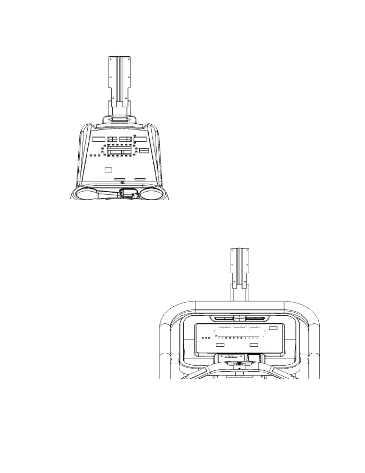
E & S TBT, RB, and UB
E & S TR
STAR TRAC UNIVERSAL TV BRACKET INSTALLATION
Page 4

4
ABOUT THIS MANUAL
This manual is applicable to the STAR TRAC E-Series & S-Series Products. The manual is divided into eight sections, as
follows:
Introduction
Provides an overview of each section within the manual.
Before You Get Started
Provides guidelines to help you have a successful installation.
Warnings and Cautions
Helpful safety tips to keep you out of harms way.
Installing Your STAR TRAC Universal TV Bracket
Provides a step-by- step instruction set for installing your TV bracket on the E-series and S-series products
STAR TRAC UNIVERSAL TV BRACKET INSTALLATION
Page 5

5
CHECK FACILITIES PREPAREDNESS
For a proper installation, please read this guide thoroughly and follow the instructions. Star Trac’s goal is to help you have a
successful and reliable installation, for this reason we have come up with some helpful tips and check list to accomplish this goal.
STAR TRAC UNIVERSAL TV BRACKET INSTALLATION
Page 6

6
CAUTION:
Disconnect power before doing any installation.
Required Tool for Installation Supplied:
• 5MM Hex Allen Key
• 3MM Hex Allen Key
• #2 Phillips Screwdriver
• Flat Screwdriver
STAR TRAC UNIVERSAL TV BRACKET INSTALLATION
Page 7

7
INSTALLING YOUR UNIVERSAL TV BRACKET KIT
The Star Trac Universal PVS Kit is different for each of your Star Trac E or S Series Cardio products. Make sure you have the
proper kit for the E or S Series product you are installing. The E- & S-UB, E- & S-RB, E- & S-TBT, and E- & S-ST will follow
the same basic steps for installation.
To install the TV neck on the E-UB, E-RB, and E-TBT, and follow these steps:
STEP1
Using a #2 Phillips screwdriver, to remove the (8)
screws on the back of the display plastic. Set the
screws aside, you will need them for reassembly.
STEP 2
After the screws have been removed, carefully open
the display plastic, so as to not detach the inner
cables from the display.
Disconnect the ground wire between the
Heart Rate board and the display mount.
STEP 3
Disconnect the 12-pin serial connector and the
Heart Rate cable from the display.
After all the cable/harnessing has been
disconnected, place the front display plastics
aside for later use. Be careful with the display and
place it face down on top of a non-scratching
surface.
STAR TRAC UNIVERSAL TV BRACKET INSTALLATION
Page 8
8
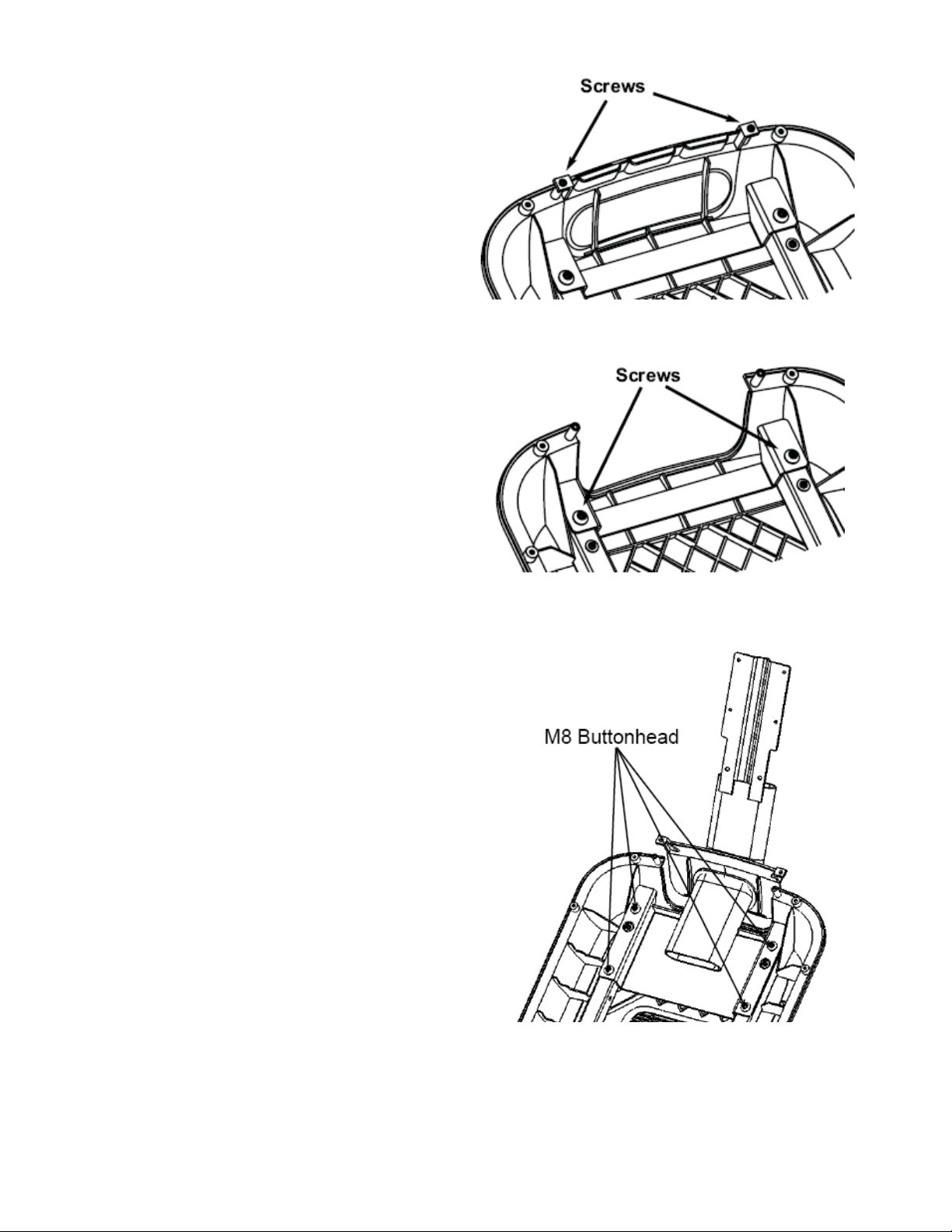
STEP4
Remove the cap cover with the Star Trac logo from the
plastics by removing the (2) screws using a #2 Phillips
screwdriver. Retain the screws for later use. You will no
longer need the cap cover and, if desired, you can store it
away for any possible future use.
STEP 5
Remove the (2) M8 button head screws retaining the cross
brace using the 5mm Hex Key. Found in the hardware kit.
Retain the screws for later use. You will no longer need
the cross brace and, if desired, you can store it away for
any possible future use.
STEP6
Take the TV neck bracket from the package. Install the
(4) M8 Button head Screws through the TV neck bracket
into the display mount. Note: (2) of the screws are in the
PVS kit, (2) retained from earlier step. Do not tighten
them at this time.
STAR TRAC UNIVERSAL TV BRACKET INSTALLATION
Page 9

9
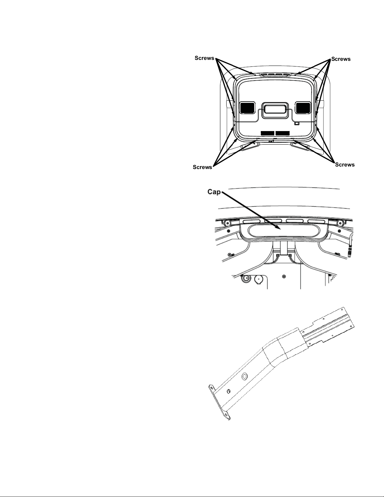
STEP7
STEP
8
STEP9
previously removed and saved.
Adjust the cap with the grommet into place. Using
the 5mm Hex Key, tighten the M8 Button head
screws to about 190 lb-in (21.5 N-m) of torque.
Take the (2) Phillips head screws you removed from
the original cap and snugly tighten screws down
using a #2 Phillips screwdriver.
Connect the ground wire back to the display mount and
connect the 12 pin serial cable back to the 12 pin socket
on the display.
And then, place the display front plastic onto the back.
Make sure the bottom of the display front is under the 2
tabs on the display mount. Press the front display against
the round tube and rotate it to the back. Be careful not to
pinch any wires.
Using a #2 Phillips screwdriver, secure the front
display to the back with the (8) screws you
STAR TRAC UNIVERSAL TV BRACKET INSTALLATION
Page 10
10
STEP1
STEP3
To install the TV neck on the E-TR, follows these steps:
Using a #2 Phillips screwdriver, to remove the (8)
screws from the upper back of the display. Place
the cover some where safe to keep it from being
damaged. Next, to remove the (6) screws from the
lower back of the display. Place the cover with the
other one. Retain all the screws for later use.
STEP 2
Now remove the upper cap cover that has the STAR TRAC
logo on it. This cap is held in by the upper back cover.
You will no longer need this cap cover and, if desired, you
can store it away for any possible future use.
Take the Personal Viewing Screen from the PVS kit.
Next, take the (2) M8 Button head screws, theM8
Hex nut with washer, and the 5mm Hex key from the
PVS hardware tool kit.
STAR TRAC UNIVERSAL TV BRACKET INSTALLATION
Page 11
11
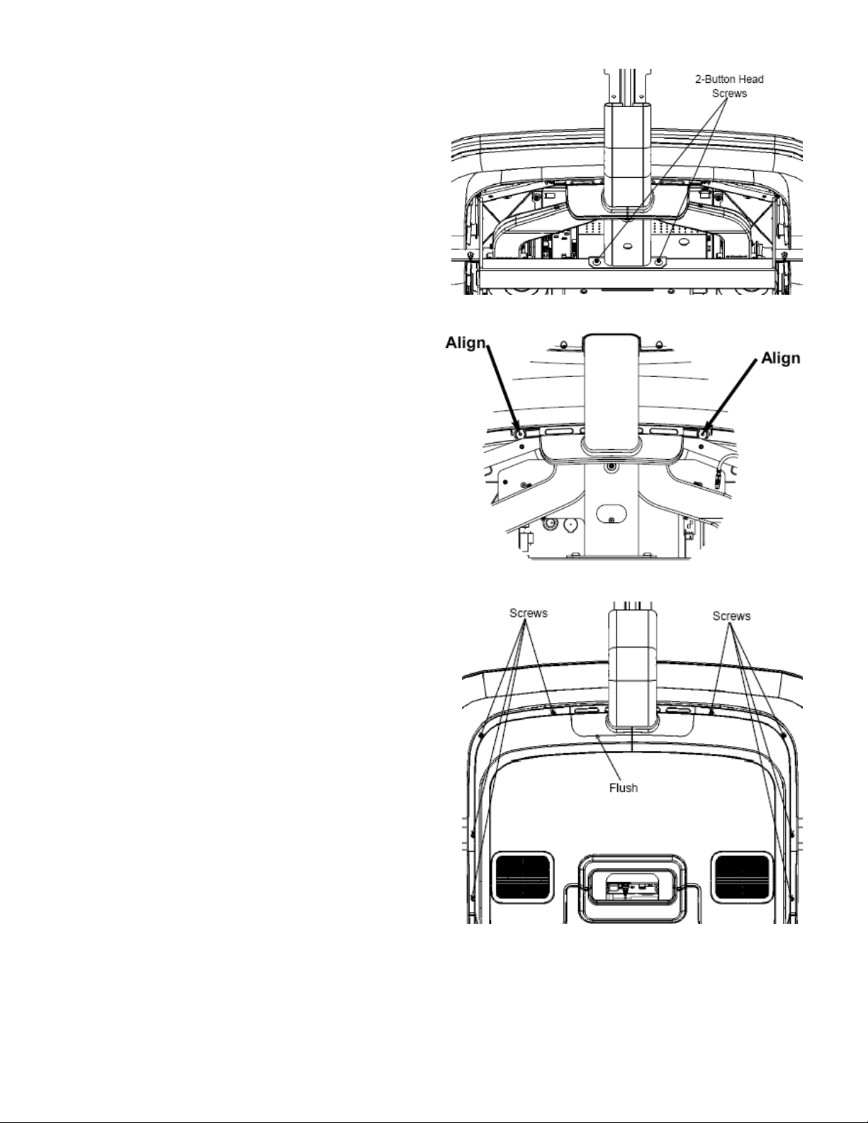
STEP4
STEP5
STEP6
Mount the Personal Viewing Screen on the
Treadmill. Using the 5mm Hex Allen Key , screw in
the (2) M8 Button heads at the base of the PVS.
Adjust the displ ay cap up or down to align with the
holes on the display front. Once the cap is aligned,
tighten the button head screws with the 5mm Hex
Allen Key .
Replace the top back plastic. Use a #2 Phillips
screwdriver insert the (8) screws, retained from
earlier step, into the plastic. Do Not tighten at this
time.
Check the cap with the neck and grommet. Make
sure the cap is flush with the top back plastic.
Adjust if necessary. Use the screwdriver to tight en the screws snug from the previous step.
Caution: Do Not over tighten screws.
STAR TRAC UNIVERSAL TV BRACKET INSTALLATION
Page 12
12
STEP1
STEP2
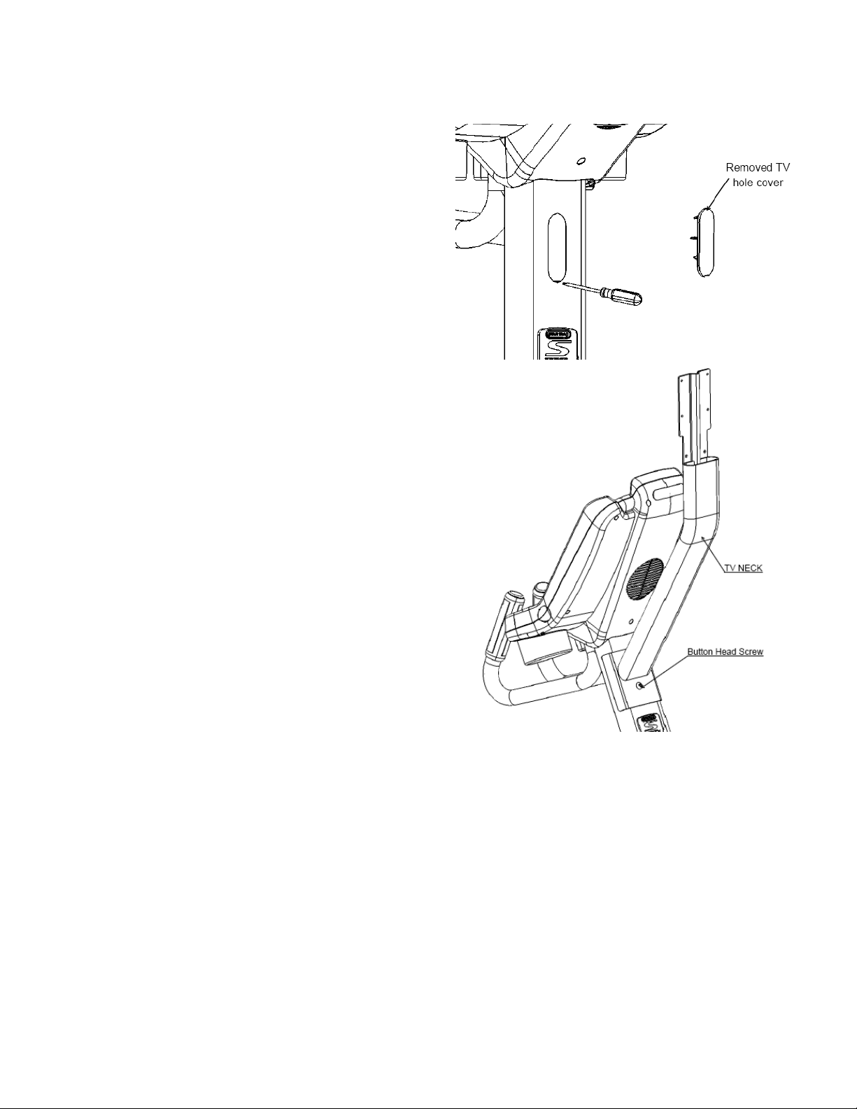
To install the TV neck on the S-UB, S-RB, and S-TBT, follows these steps:
Remove the TV hole cover:
On the back side of the neck tubing, using a flat
screwdriver, unclench the TV hole cover from the
notch. (The cover is not used anymore, but you may
save it for future use as you lik e.)
Install TV bracket:
Using a 5mm Hex Allen Key , install the TV bracket
to the neck tubing with a 8mm button head screw.
STAR TRAC UNIVERSAL TV BRACKET INSTALLATION
Page 13
13
BACK
STEP
2
STEP
3
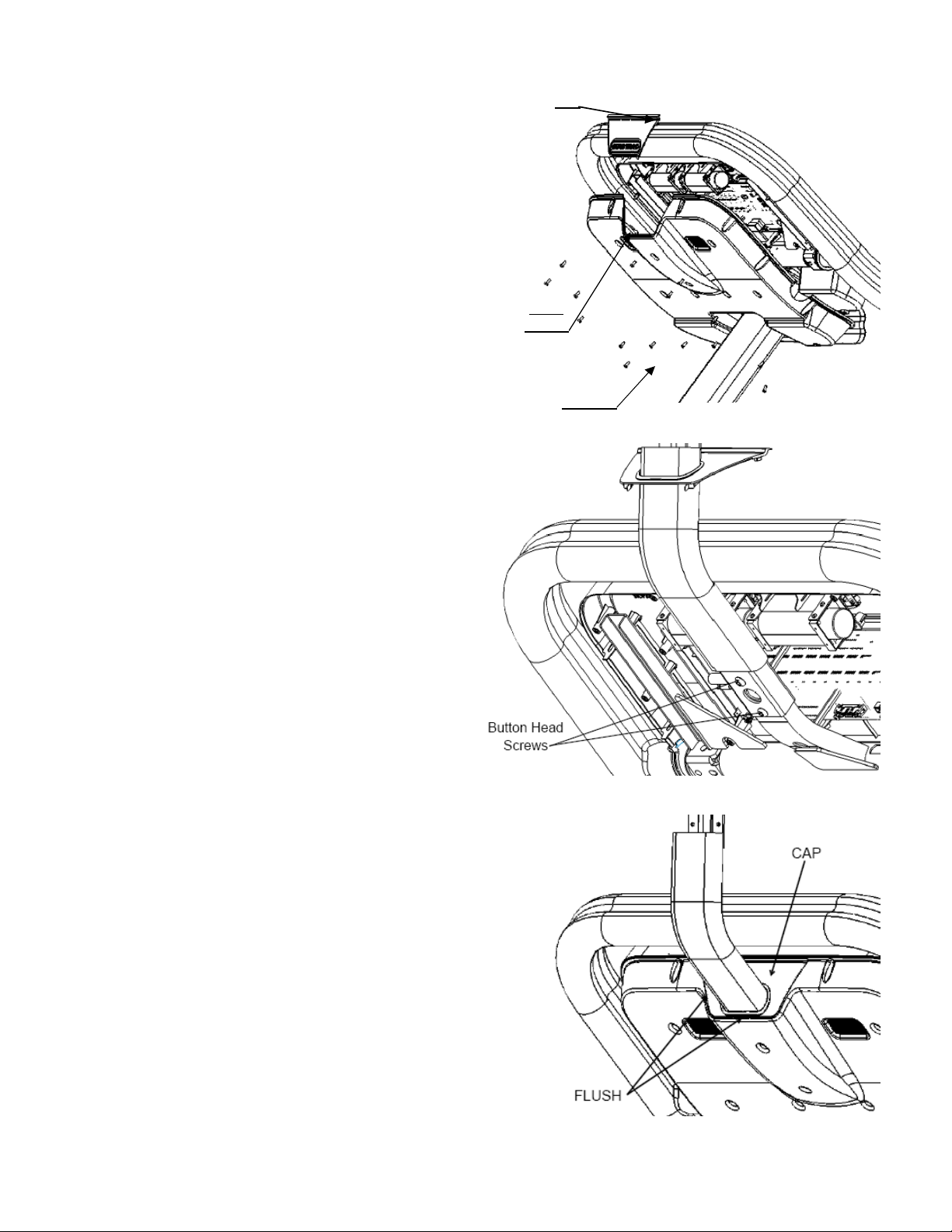
To install the TV neck on the S-TR, follows these steps:
STEP 1
Using a #2 Phillips screwdriver, to remove the (19) screws
from the back of the display. Next, remove the back cover
and the upper cap cover with “Star Trac Logo on it (You
will no longer need this cap cover and, if desired, you can
store it away for any possible future use).
CAP
COVER
Take the TV bracket from package and remove the
bubble wrap. Insert the bracket into the rectangle
tube. Using a 5mm Hex Allen Key to fasten (2) M8
button head screws with (2) washers.
SCREWS
Replace the top back cover. Use a #2 Phillips
screwdriver insert (19) screws, retained from earlier
step, into the plastic cover. Do not tighten now.
Check the Cap with the neck and grommet. Make
sure the Cap is flush with the top back plastic, and
adjust if necessary. Use the screwdriver to tighten
the screws, but don’t over tighten screws
STAR TRAC UNIVERSAL TV BRACKET INSTALLATION
Page 14

14
Hex
Step 1
Step 2
1. TV with 75x75
mm mounting hole pattern:
2. TV with 100x100
mm mounting hole pattern:
To install the TV on the bracket follows these steps:
Install your TV onto the bracket, by using a 3mm
Allen Key
washers, as shown.
And then, insert the tubing cap on the tube opening.
to fasten (4) M4 socket head screws and (4)
Install your TV onto the VESA bracket with (4)
M4 ACORN nuts and (4) washers, as shown.
If the mounting hole pattern on your TV is 75x75mm, you
have to install the VESA bracket (packed with hardware
kit) onto your TV with (4) M4 socket head screws, as
shown.
STAR TRAC UNIVERSAL TV BRACKET INSTALLATION
Page 15

15
14410 Myford Road
Irvine, California 92606
Telephone: (800) 228-6635, (714) 669-1660
Fax: (714) 508-3303
http://www.startrac.com
STAR TRAC
P/N: 620-7841, Rev. B
STAR TRAC E&S SERIES UNIVERSAL PVS INSTA LLATION MANUAL
 Loading...