


727-0083
Star Trac Fitness™
Spinning® Computer
User Manual
Installation, Service and Instructor Education


Table of Contents
_________________
_______________________________
____
____________________________
____________________________
______________
______________
_____________________
_________________________
___________________________
_____________________________
_______________________
________________________________
__________________
____________________
____________________
________________
_____________
________________________________
________________________________
________________________________
________________________________
________________________________
________________________________
eries________________________________
-sync?________________________________
________________________________
________________________________
________________________________
Sensor and Magnet – All Spinners®
- V-Bikes
- Pro 5800 / 6800 / Elite 5900
On Handlebars - Elite 6900 and NXT 7000
________________________________
________________________________
________________________________

1
This device complies with Part 15 of the FCC Rules. Operation is subject to the following
two conditions: (1) this device may not cause harmful interference, and (2) this device
terference that may cause undesired
Changes or modifications not expressly approved by Star Trac could void the user’s
FCC Regulatory Statements
1.
must accept any interference received, including in
operation.
2.
authority to operate the equipment.
2
for mounting on your bikes
1660 to
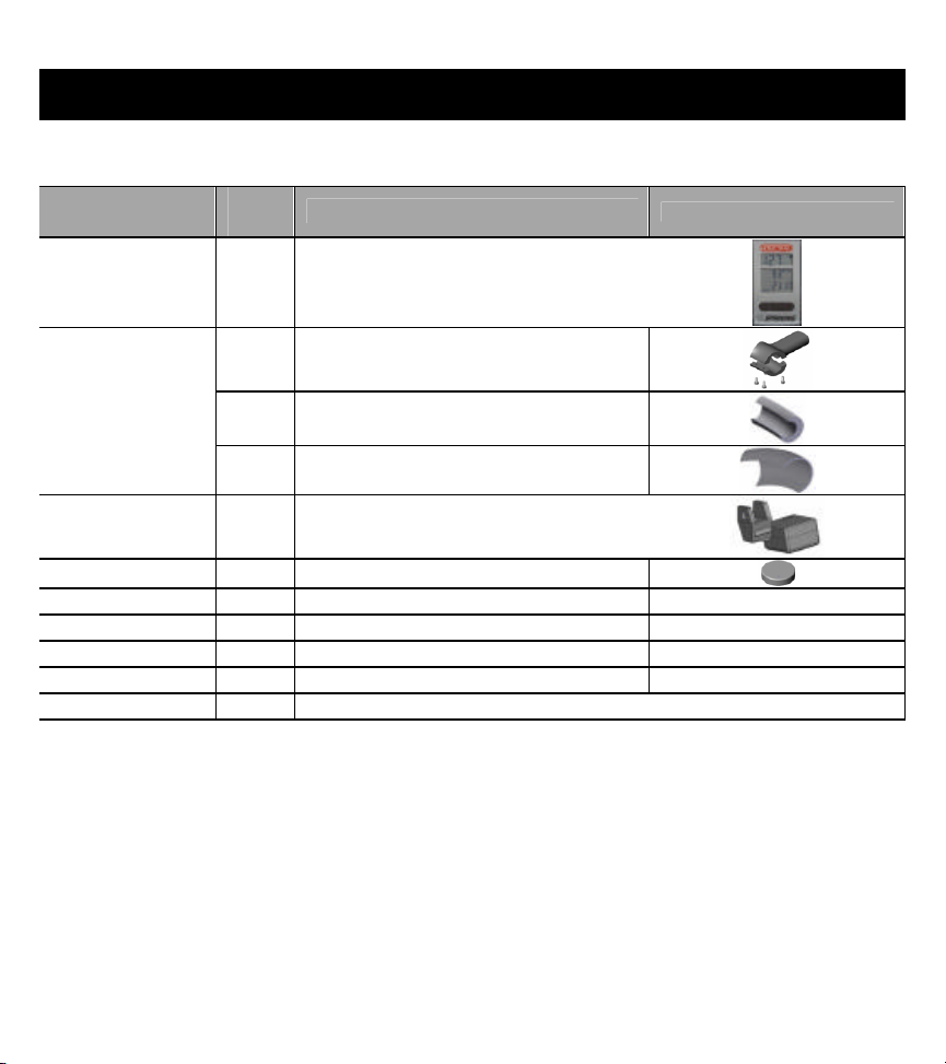
Parts List
All 727-0083 Spinning® Computer Kits include:
for
re-order
Qua
ntity
Description
727-0083
Spinning ®
1 Spinning® Computer
Computer Kit
1 Mounting Bracket
727-0093-KT
Mounting
1 V2 Bracket Mounting Insert
Bracket Kit
1 Pro Bracket Mounting Insert
727-0084-KT 1 Cadence Sensor
727-0094 1 Cadence Magne t
N/A 4 AA Panasonic Batteries
N/A 1 Spinning® Computer Manual
N/A 1 M5 Allen Assembly Tool
N/A 1 M2 Allen Assembly Tool
N/A 1 M6x30 Computer Clamp Screw for Rhino Horn
®
Computer, verify that all the parts needed
-503-1221 or 1-714-669-

3
WearLink
Only Coded Transmitter will allow
potential “crosstalk”
significantly
Computer on one
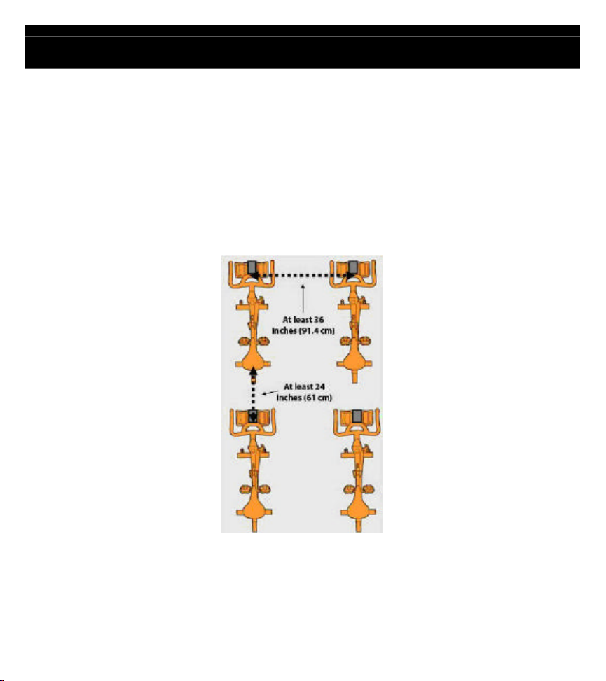
Computer on bikes to the left or right is at least 36 inches (91.4 cm). In
Computer on one bike to the seat of the
bike in front of it (where another rider and his/her transmitter would be seated) should be at least
rference. See the diagram on
Marketing Statement Regarding Heart Rate
Star Trac Spinning® Computer:
on possible to acquire an accurate heart rate signal as well as eliminate “crosstalk”
®
Computer, please abide by the following
Users must wear Coded Transmitters (such as Polar© T61, Polar© T31C or Polar
©
when operating the Spinner® bike with the Spinning® Computer.
a “one to one” relationship with the Spinning® Computer and will minimize
interference. If users wear non-coded straps, there is significantly increased potential for
“crosstalk” which will cause erratic heart rate display, loss of heart rate display and
reduce the consistency of accurate heart rate reporting.
Bikes should be spaced so that the side-to-side distance from the Spinning
bike and the Spinning
addition, the distance from the bottom of the Spinning
®
®
®
24 inches (61 cm) in order to significantly reduce chances for inte
page 21 regarding bike layout.
4
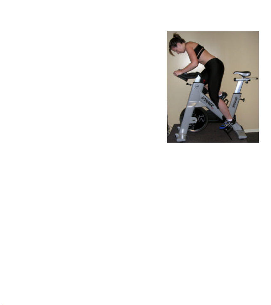
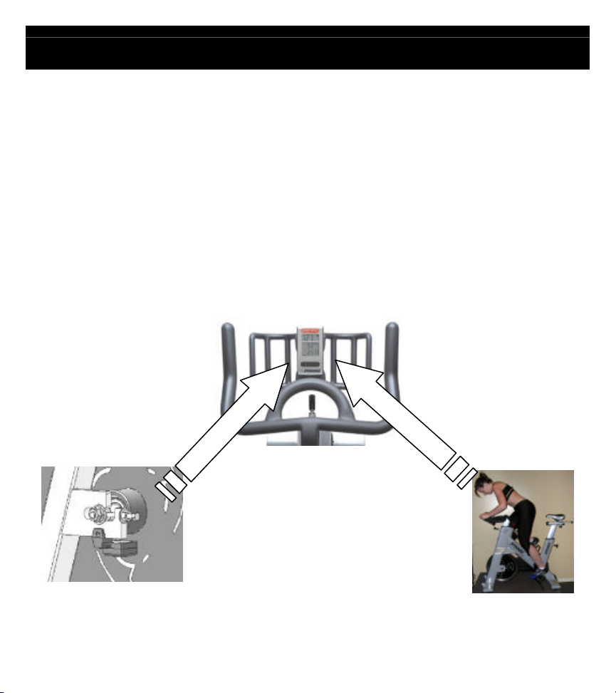
Riders must lean into the
Calorie calculations are displayed as a summary only and will ONLY be shown if a user utilizes a
the
display (within 16 inches) and
wait for the HR to display –
once the HR is displayed they
must maintain the forward
Position for 15 seconds while
the computer codes with their
Polar Coded Strap, this insures
that no outside signals will interfere
with the riders data once they lean
back into their seated position.
heart rate strap throughout the entire workout.
Cell phones, televisions, speakers and other electronic devices can cause interference with
operation if they are in close proximity to the Spinning® Computer and/or transmitter.
s regarding operation or usage of the Spinning® Computer, please contact
-503-1221 or 1-714-669-1660.
5
strap
Specifications
Heart Rate Range : Approximately 30” From computer to users HR chest
Battery: Qty 4 each AA Alkaline
Battery life expectancy: 1 year (depending on use and backlight usage)
Sensor:
Battery: Lithium CR2032
Battery life expectancy: Approximately 2.5 Years (depending on use)
Distance to magnet: Approximately 5mm
6
by the person riding the Spinning Bike. The Polar strap
displays the person’s heart rate.
The computer and heart rate
hin range of each other and no other heart rate strap can be within this
computer
How it Works
Heart
How does the Spinning computer work?
speed), total distance and elapsed time.
• The heart rate information is received from a Polar
WearLink® heart rate strap worn
sends a radio signal to the computer and the computer
If any other strap is used it will not display the heart rate.
strap must be wit
imaginary circle. The range is approximately 36 inches from the computer.
©
T61, Polar© T31C or Polar©
• The RPM signal is transmitted by the cadence sensor sending the RPM to the
Each time the magnet on the flywheel passes the cadence sensor it records one
revolution and as it counts the revolutions it sends this number to the computer.
RPM
rate
7
ollowing data will be
iles or kilometers depending on the setup
The length of time in minutes from the time the computer has been
Turns on the backlight to enable viewing in low
Toggles between: Total Distance and
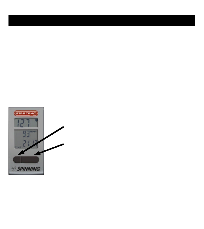
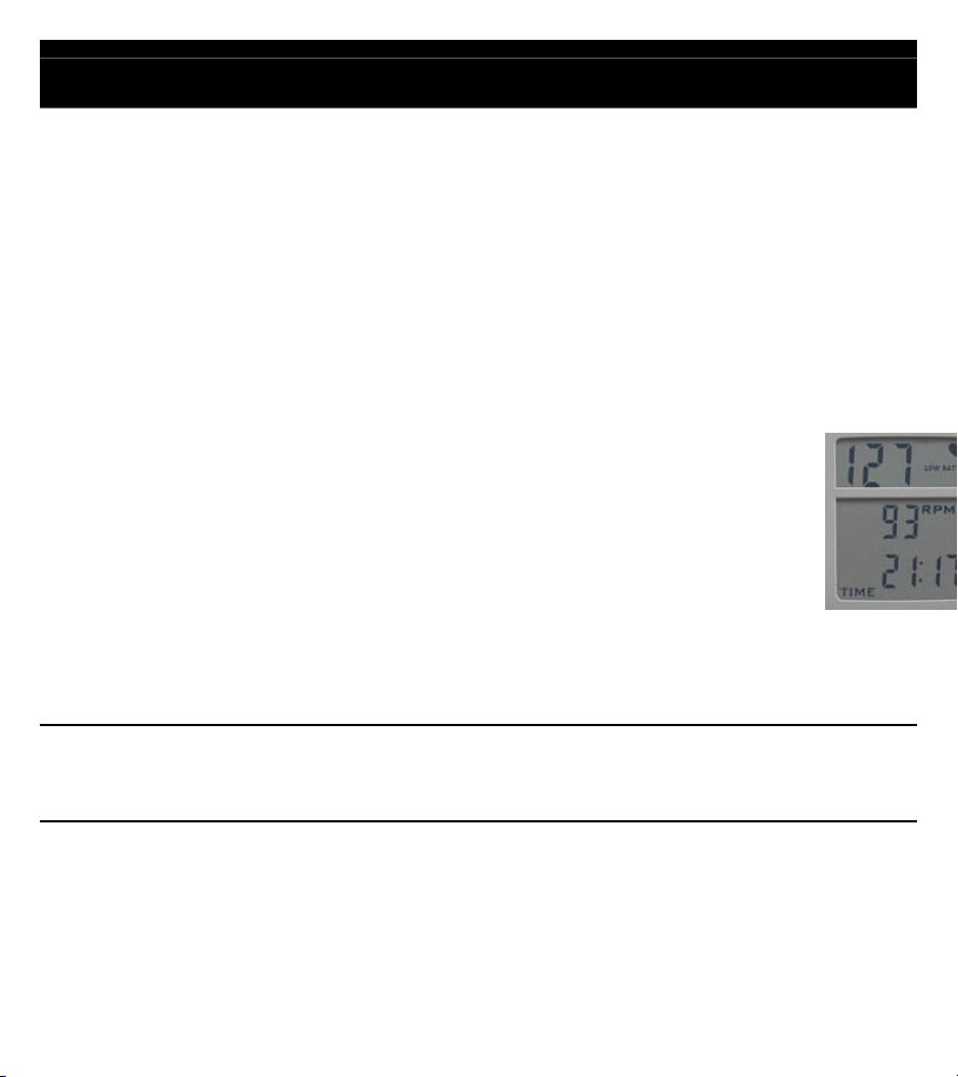
Computer Window and Buttons
Spinning® Computer; the f
HR- Displays the Heart Rate of the user when wearing a compatible Polar® HR
telemetry strap in beats per minute.
RPM- Shows the pedaling speed of the user in revolutions per minute.
Total Distance - Distance measured in m
selection.
Elapsed Time –
activated or reset.
Buttons:
Light (left) button -
light settings.
Toggle (right) button -
Elapsed Time.
8
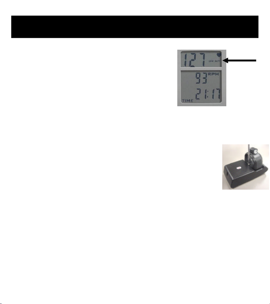
Low Battery
Indicator
Installing or Replacing Batteries
5 Minutes
4 new AA alkaline batteries
Slotted or Phillips screwdriver
ries in the computer will last approximately
Remove the computer from the handlebar or computer mounting
bracket.
Loosen the captive scre w on the back of the battery cover (screw will
not completely come off, it will remain captive.) To remove the cover,
pull on the captive screw and lift.
Install 4 new batteries. Note: Replace all 4 batteries at the same time.
9
) symbol
The + sign indicates the positive (+) side on the battery and
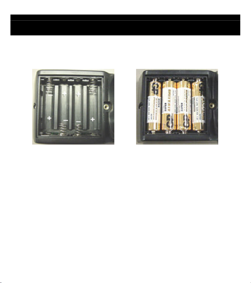
Installing or Repla cing Batteries – cont’d
Note the directions each battery is to be installed. There is a plus (+) and minus (inside the battery compartment.
the - indicates the negative (-) side on the battery.
Insert each of the 4 batteries into the battery compartment of the computer.
Attach the battery cover and tighten the screw.
Attach the computer onto the handlebar or computer mounting bracket and test.
10
: Syncing will not improve Heart Rate and is not a calibration it should only be used to Sync
A loose battery will prevent the cadence sensor to transmit the RPM signal to the
A missing magnet or one that is not lined up properly will prevent the cadence sensor
above steps you may now sync the computer and
cadence sensor. This will make them a paired set and will be able to transmit and
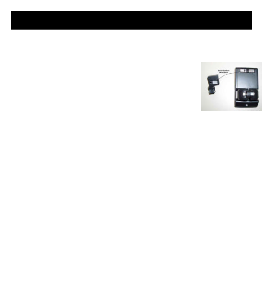
Do I need to Re-sync?
after checking all of the following:
• Do the serial numbers on the cadence sensor and the
computer match?
o If they do not match the handlebar has been swapped
with another bike and should be swapped back, so the
computer and sensor are matched up again.
• Is the battery secure in the cadence sensor and the cover is not loose?
o
computer.
• Is the magnet aligned with the cadence sensor?
o
to transmit the RPM signal to the computer.
• Does the computer turn on when you press a button?
o If the computer does not turn on replace the batteries in the computer.
• The computer turns on but as you pedal it does not show the RPM.
o If you have performed all of the
receive the RPM signal.
11
the
the Cadence sensor and computer will have to be
n the same
Testing for RPM
Less then 5 Minutes
N/A
N/A
T Procedure:
Once the batteries are installed, press any button and the display window will turn on in
Workout mode.
Test by waving a magnet across the cadence sensor. If you see RPM
values, then the cadence sensor and computer was synced successfully,
there is no need to perform the sync process.
If you do not get any rpm reading and the computer turns off you WILL
need to perform the Syncing process.
: If the cadence sensor and computer are no longer a pair (i.e. when users swap
th the computer attached.)
, the range for the cadence sensor is
 Loading...