

Page 1
Training Manual
Part Functionality
E-TBT (Model 9-6080) LED Display
In this section, we will review all the components that make up the E Series E-TBT (Total Body Trainer). To resolve issues
that may occur on an E-TBT, it is important to understand all the components and what function they play in the system.
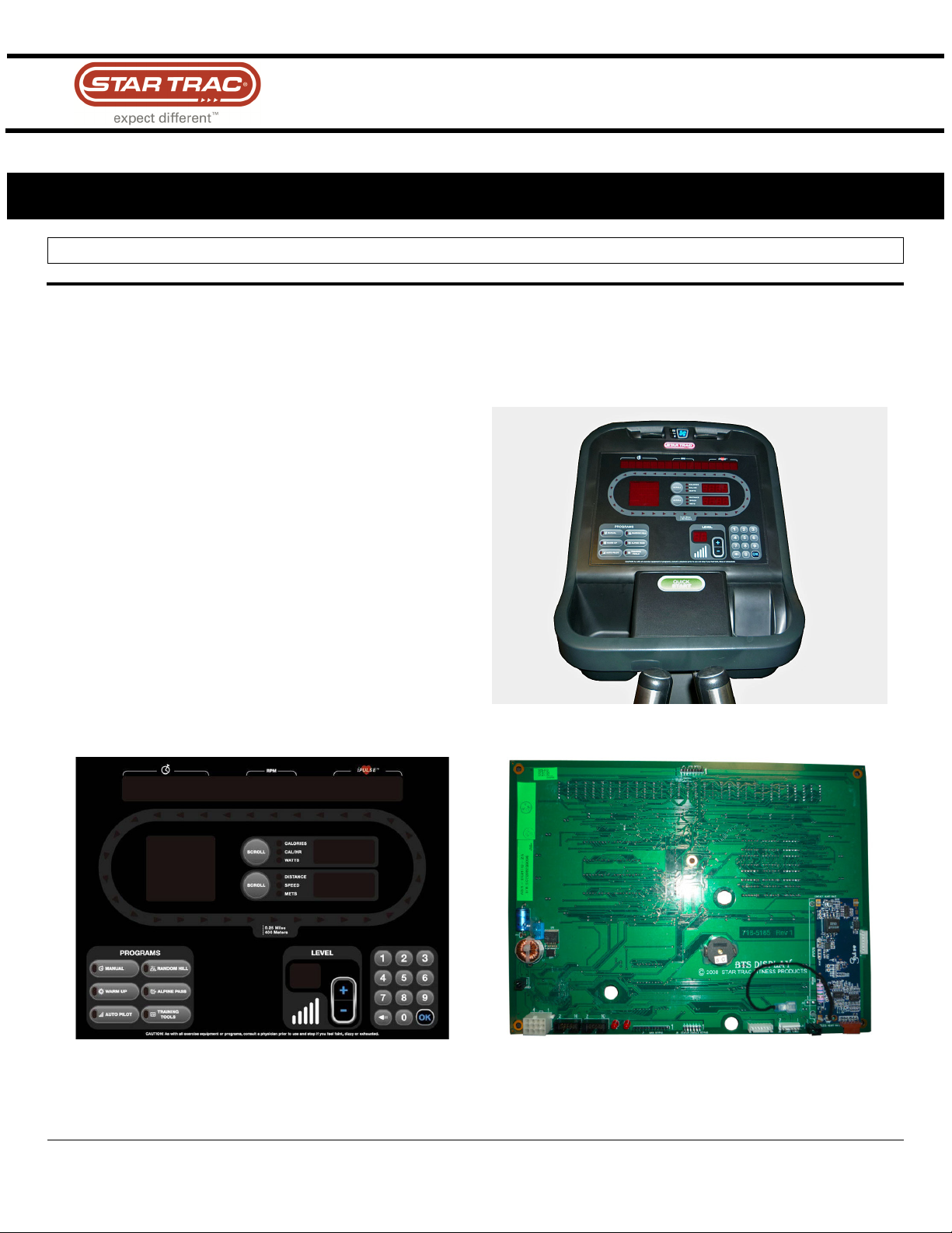
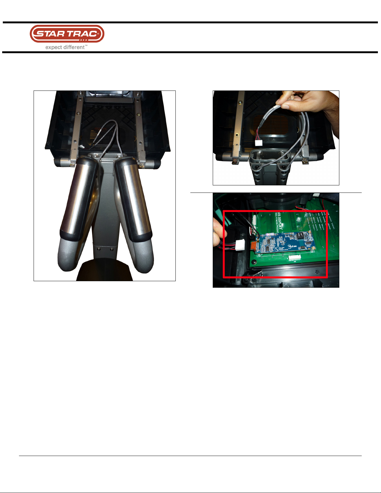
1. Display Assembly (LED)
The display assembly is like the brains of the unit. It
controls and commands the TBT to take actions. It is the
user interface to control the machine. It also does the
following:
• RPM Calculations
• Calorie Calculations
• Pre-designed Programs
• Heart Rate Calculation
There are two main components to the display assembly:
Display Panel
STAR TRAC FITNESS
1 of 19
Display Electronics
637-1377 Rev: A
Page 2
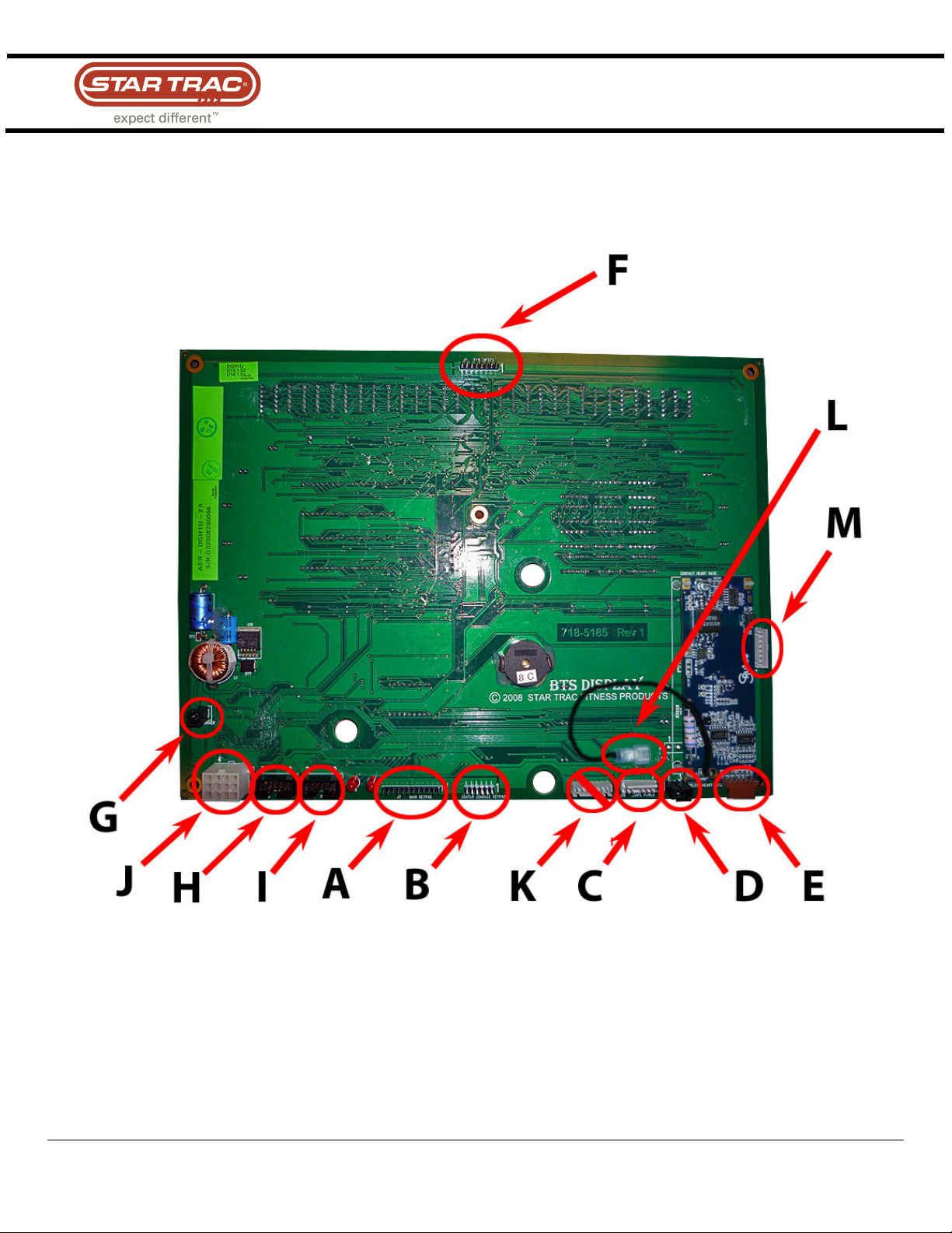
Components that Connect to the Display Electronic:
Training Manual
STAR TRAC FITNESS
2 of 19
637-1377 Rev: A
Page 3
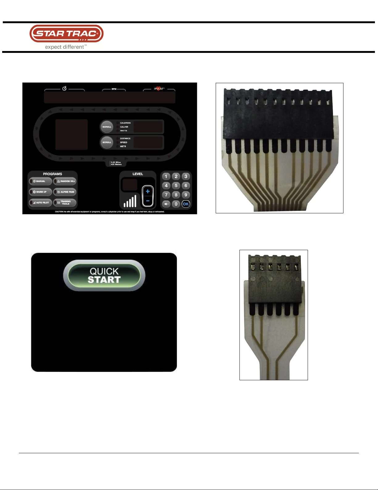
A. Display Panel
(J7 –
12 Pin
Connector
)
B. Center Console
(J8 –
6 Pin
Connector
)
Training Manual
–The main keypad that is used to enter commands.
–The small keypad that has the ‘Quick Start’ key. If the unit has any kind of
entertainment, there will be extra keys for that.
STAR TRAC FITNESS
3 of 19
637-1377 Rev: A
Page 4
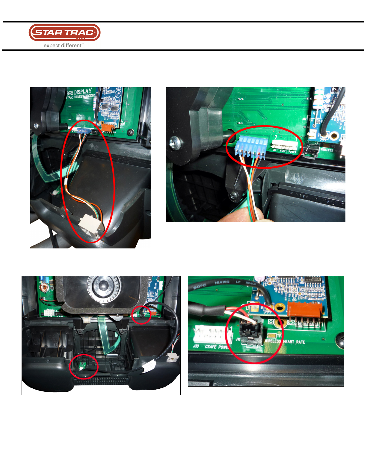
C
. CSAFE Power
(J10
– 6
Pin Conn
e
ctor
)
D
. Polar Receiver
(J11
– 3
Pin Connector
)
to external add on audio accessories.
Training Manual
– The external CSAFE port. Note: This port is only used for supplying power
– The telemetry/wireless heart rate (signal sent out by the chest strap).
STAR TRAC FITNESS
4 of 19
637-1377 Rev: A
Page 5
E
. Contact Heart Rate
(6 Pin Connector on the standoff HR Board)
The contact heart rate is typically mounted on the display electronics.
Training Manual
– The contact heart rate board plugs in here. Note:
STAR TRAC FITNESS
5 of 19
637-1377 Rev: A
Page 6
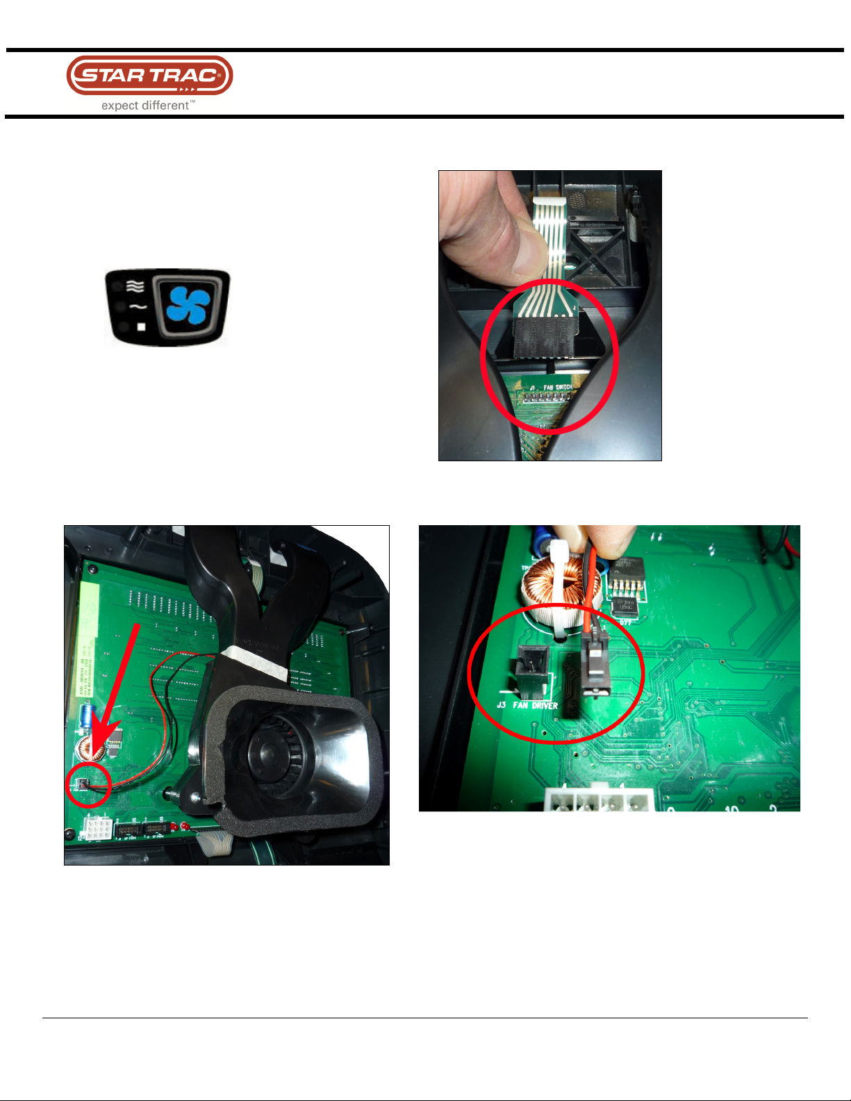
F
. Fan Keypad
(J1 –
8 Pin Connector)
G
. Fan Power
(J3 – 2 Pin Conn
ector)
Training Manual
– The small keypad at the top of the display housing.
– The fan gets power from the display electronic.
STAR TRAC FITNESS
6 of 19
637-1377 Rev: A
Page 7

H
. Primary
Port (J6 –
10 Pin Connector)
I
. Secondary Port
(J5 – 10 Pin Connector)
software into the display.
Training Manual
– The primary port for uploading
software into the display.
– The secondary port for uploading
STAR TRAC FITNESS
7 of 19
637-1377 Rev: A
Page 8

J
. Display Cable
(J4 –
12 Pin Conn
e
ctor)
Training Manual
– This is the main cable that connects the display to the LCB.
The display cable is like the nerves of the TBT. Information and power are sent up to the display and back down to the
LCB to control the unit. The display cable passes:
• Power to the display
• Commands for resistance level
• Signal for RPM
The Data Cable is polarized so it can not be plugged in incorrectly.
STAR TRAC FITNESS
8 of 19
637-1377 Rev: A
Page 9

K. TV Interface (J9
– 7 Pin Connector)
–
L.
HR Board Ground Cable
(connects to the display frame)
Training Manual
NEVER use this port.
STAR TRAC FITNESS
9 of 19
637-1377 Rev: A
Page 10

M. CCB (J14
– 7 Pin Connector)
Training Manual
Used for PVS and on ‘made for iPod’ kits only.
STAR TRAC FITNESS
10 of 19
637-1377 Rev: A
Page 11

2. Load Control Board (LCB)
Location of the LCB:
Training Manual
STAR TRAC FITNESS
11 of 19
637-1377 Rev: A
Page 12

Training Manual
The LCB is the heart of the TBT. The LCB brings the power from brake and conditions it for distribution to the display
electronic.
STAR TRAC FITNESS
12 of 19
637-1377 Rev: A
Page 13

A. Brake Style Selector Switch (J2)
–
B.
CN7
- 8 Pin Connector
–
Training Manual
Connections and Components that plug into the ADT LCB (PN: 721-1176)
This switch allows the LCB to work with either brake style see document number
637-1348).
This connector is not used on this generation of the E Series TBT. The previous generation
with Upper Body Arm movement (Select Fit) need this connector.
STAR TRAC FITNESS
13 of 19
637-1377 Rev: A
Page 14

C. Battery Connector (CN3
– 2 Pin Connector)
–
D.
External Power Connector (CN2
– 3 Pin Connector)
–
the battery.
Training Manual
Delivers power to the display when there is no movement and charges
Supplies 12 Volts to the system.
STAR TRAC FITNESS
14 of 19
637-1377 Rev: A
Page 15

E
. C-Save Connector (J1
– 8 Pin)
–
F. Display Cable Connector (CN1
– 12 Pin Connector)
–
Training Manual
This is where the external C-Safe cable plugs in to the LCB.
down to the LCB to control the unit.
Information and power are sent up to the display and back
STAR TRAC FITNESS
15 of 19
637-1377 Rev: A
Page 16

G. Generator Cable Connector (CN4
– 3 Pin Connector)
–
H. Brake Cable Connector (CN5
– 2 Pin Connector)
–
.
Training Manual
Brings in the power from the generator.
Controls the brake resistance
STAR TRAC FITNESS
16 of 19
637-1377 Rev: A
Page 17

A. Drive belt
–
3. Mechanical/Drive Components:
This belt connects the main pulley with the generator/brake to produce the needed voltage and create
resistance when the user wants that.
Training Manual
STAR TRAC FITNESS
17 of 19
637-1377 Rev: A
Page 18

B. Belt Tensioning Lever
C. Drive Shaft A
lignment Screws
Training Manual
– Assures that the tension of the drive belt is always at the right level.
both sides of the drive shaft.
– These are used for proper drive shaft/drive belt alignment. They are located on
STAR TRAC FITNESS
18 of 19
637-1377 Rev: A
Page 19

D.
Leg Roller and Guide Rod
Training Manual
– They are exposed to a lot of load. Front to rear motion only.
STAR TRAC FITNESS
19 of 19
637-1377 Rev: A
 Loading...