

Star Trac Pro CrossTrainer Elite CrossTrainer, Pro CrossTrainer, Elite CrossTrainer Service Manual
Page 1
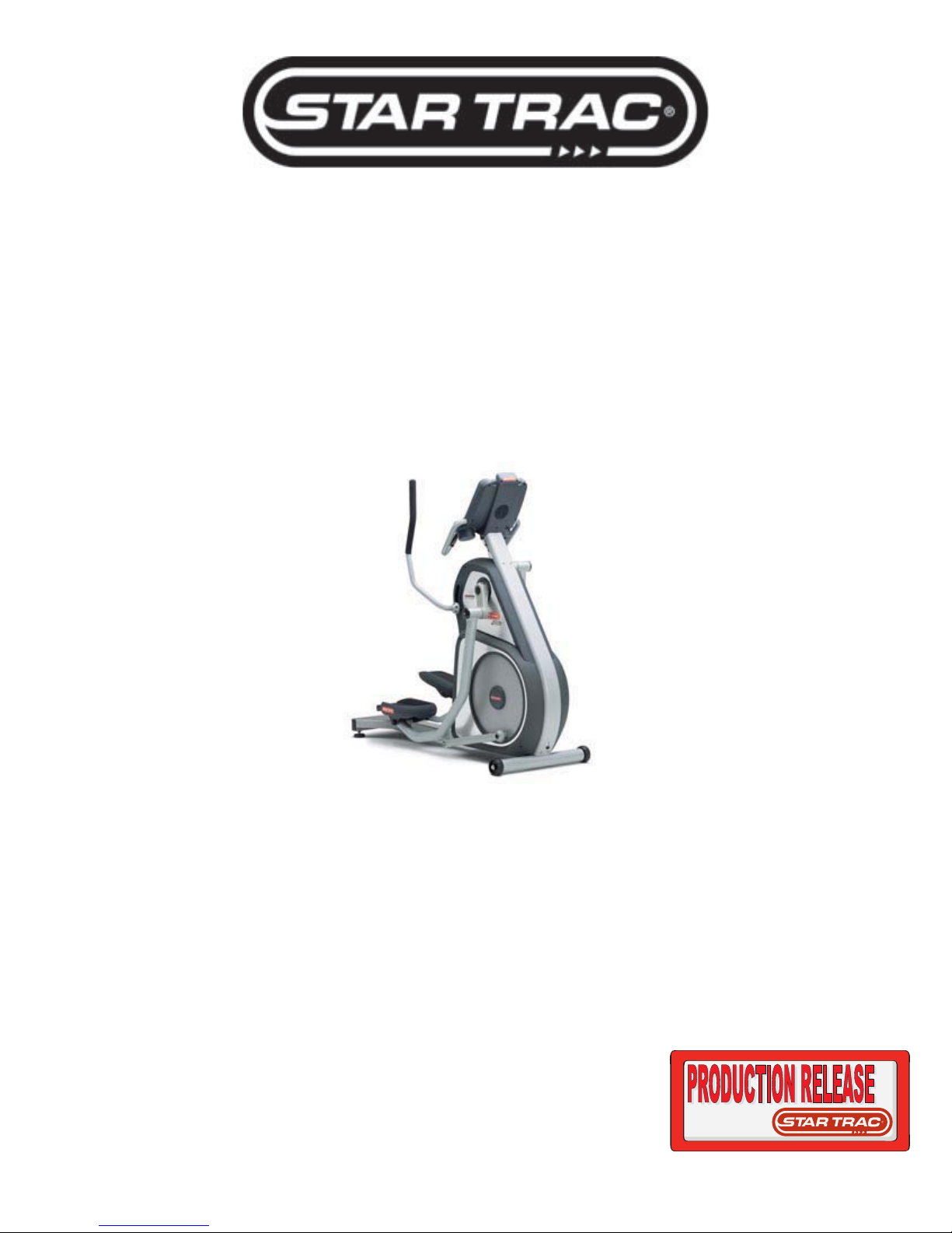
Pro CrossTrainer
Elite CrossTrainer
Service Manual
Page 2

CrossTrainer Service Manual
Table of Contents
Table of Contents ..............................................................................................................................................................1
Preventive Maintenance....................................................................................................................................................2
Settings - Maintenance Mode..........................................................................................................................................3
Diagnostics - Display Codes ........................................................................................................................................... 5
Diagnostics - LED Test ....................................................................................................................................................6
Diagnostics - Keypad Test............................................................................................................................................... 7
Diagnostics - Heart Rate Test, Measurements .............................................................................................................. 8
Diagnostics - UB Calibration...........................................................................................................................................9
Trouble Shooting - Incorrect Model Setting ................................................................................................................10
Trouble Shooting - Noises : Pinging .............................................................................................................................11
Trouble Shooting - Noises : Bearings ........................................................................................................................... 14
Trouble Shooting - Excess Lateral UB Arm Movement...............................................................................................17
Part Installation Procedure - Shrouds..........................................................................................................................18
Part Installation Procedure - Keypad ...........................................................................................................................21
Part Installation Procedure - LCB, Batt. And UB Board ............................................................................................. 23
Part Installation Procedure – Upper Crank Arm........................................................................................................... 27
CrossTrainer Parts List................................................................................................................................................... 30
1 CrossTrainer Service Manual Rev A 620-7575
Page 3
CrossTrainer Service Manual
Preventive Maintenance
To keep your Star Trac CrossTrainer in top condition, Star Trac strongly recommends performing
regular daily, weekly and monthly preventive maintenance routines outlined below.
Daily Maintenance
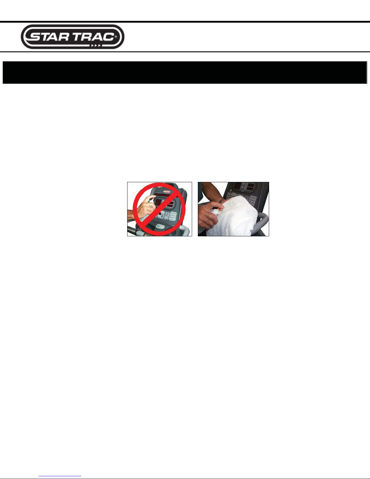
x Remove excessive accumulations of dust, dirt and other substances by using a clean, soft
cloth and a non-abrasive liquid cleaner, such as Formula 409™ or FANTASTIK™. Wipe down
the exterior of the display panel, upper body arms, pedals, shrouds and heart rate grips.
Note: Do not spray directly on the display or heart rate grips.
Spray on the cloth first.
Weekly Maintenance
Perform the following services each week:
x Vacuum the floor under and around the CrossTrainer. Move the unit to another spot, if
necessary, to vacuum thoroughly.
x Inspect the screws (i.e. display panel mounting screws) for security, and retighten if
necessary.
x Inspect the display panel keypads for wear.
Monthly Maintenance
Perform the following services each month, or as needed:
x Check that the pedals and shrouds are secure.
x Check the upper body arms for looseness. Tighten screws when necessary.
x Check for smooth and quiet operation of all moving parts.
2 CrossTrainer Service Manual Rev A 620-7575
Page 4

CrossTrainer Service Manual
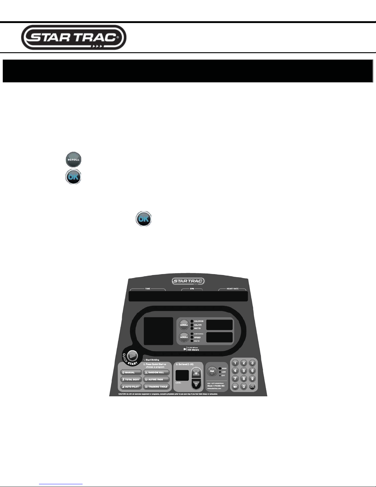
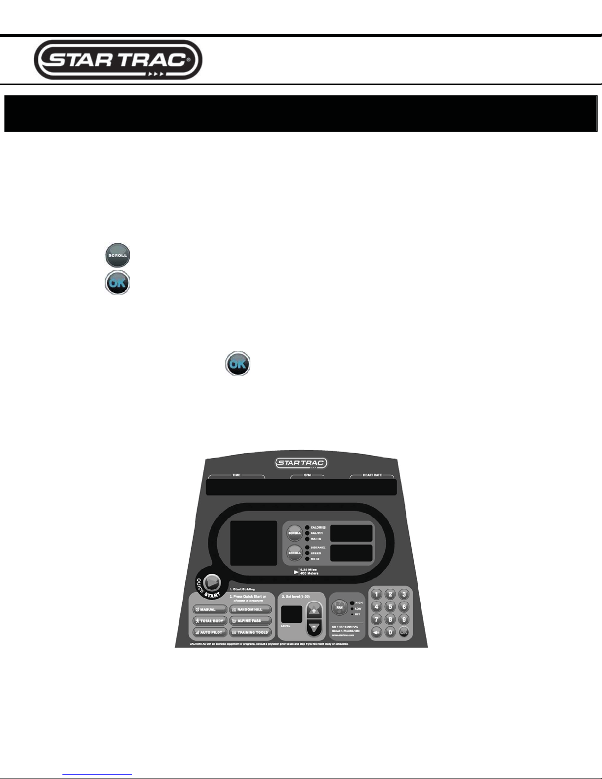
Settings - Maintenance Mode
The Maintenance Mode allows you to query and modify the basic settings of the Star Trac
CrossTrainer.
Engaging Maintenance Mode
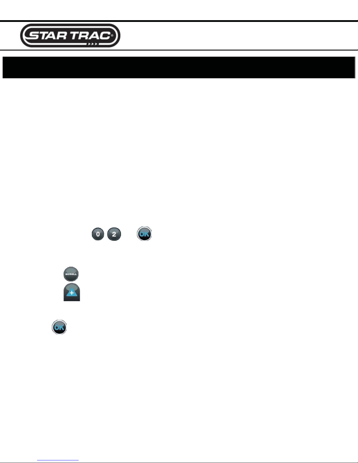
1. Press and hold the , and keys together.
2. A beep will sound and the “MAINTENANCE MODE” will display momentarily in the information
window.
3. Release all keys. “SERIAL NO XXXXX” will display in the information window.
Modifying the Maintenance Mode
The following keys are used to modify Maintenance Settings:
Upper and Lower Data Information Window SCROLL keys: Display the next and
previous settings.
Increase and Decrease Level Keys: Adjust the value of the displayed setting up
and down respectively, in increments of 1 unit.
OK Key: Updates (saves) the value of the display setting in the Flash memory, and exits
Maintenance Mode.
Maintenance Mode Settings
The items that you may display and change:
Default values set in ()
Serial Number
Date
Display Vers 1
Display Vers 2
LCB Vers
Units
Time
Weight
CrossTrainer serial number (0)
Manufactures date for the CrossTrainer (07/03)
Display software version (N/A)
Display software version (N/A)
LCB software version (N/A)
English = units of pounds, miles, feet inches; (English)
Metric = units of kilograms, kilometers, centimeters
Maximum time in minutes allowed for program, excluding warm-up and cooldown (20)
Default (to user), typical weight in lb (UNITS=English) or kg (UNITS = Metric)
(155 lbs, 70 KG)
3 CrossTrainer Service Manual Rev A 620-7575
Page 5

CrossTrainer Service Manual
Settings - Maintenance Mode (cont.)
Language
Model
LCB Ver2
CSAFE
Auto Status
Wall Power
IRDA
OPER Hours
Quick Start
Manual
TB Begin
TB Inter
TB Diff
Auto Pilot
IHR Pro
CHR Pro
CW Pro
Alpine
Rndm Prog
UB Revs
Comm Lost
Key Down
Batt Low
Repl Batt
LED Test
Keypad Test
Heart Rate Test
Measurements
UB Calibration
Language is English, Dutch, French, German, Spanish, Swedish, Italian or
Katakana (English)
PB-UB = Pro Bike Upright, PB-RB = Pro Bike Recumbent, Pro CT = Pro
CrossTrainer, Elite CT = Elite CrossTrainer, Stepper = Pro Stepper
LCB hardware version (N/A)
Turns on/off CSAFE functionality (Off)
Turns on/off the unsolicited status of the CSAFE feature (Off)
Turns the wall power setting on/off (Off)
Turns on/off infrared port functionality (Off)
Total operating hours (0)
Number of times the Quick Start program was run since last reset (0)
Number of times the Manual program was run since last reset (0)
Number of times the Total Body – Beginner program was run since the last
reset (0)
Number of times the Total Body – Intermediate program was run since the last
reset (0)
Number of times the Total Body – Difficult program was run since the last reset
(0)
Number of times the Auto Pilot program was run since the last reset (0)
Number of times the Interval Heart Rate Control program was run since the last
reset (0)
Number of times the Constant Heart Rate Control program was run since last
reset (0)
Number of times the Constant Watt Control program was run since the last reset
(0)
Number of times the Alpine program was run since last reset (0)
Number of times the Random Hill program was run since last reset (0)
1/40 the number times the UB motor pot has turned
Number of times a Comm Lost condition has occurred. See Display Codes
Number of times a Key Down condition has occurred. See Display Codes
Number of times a low battery condition has occurred. See Display Codes
Number of times the need for battery replacement has occurred. See Display
Codes
Access to integral LED test function
Access to integral keypad test function
Access to integral heart rate system test function
Access to integral measurements function
Access to integral upper body system calibration function
4 CrossTrainer Service Manual Rev A 620-7575
Page 6

CrossTrainer Service Manual
Diagnostics - Display Codes
Display Codes
Star Trac CrossTrainers perform a self-test at the beginning of every workout. If a problem is
detected, a message displays before or after the workout, depending on the nature of the problem.
Key Down – One or more keys on the display panel are stuck in the “on” position for at least 10
seconds. This can occur if a user presses keys before the system is turned on.
Comm Lost – Communication between the Load Control Board (LCB) and the display are lost. This
can occur if the display cable is not connected securely at install.
Batt Low – Upper body actuator is commanded to work and the battery voltage is less than 5.7 volts.
Repl Batt – Upper body actuator is commanded to work and the battery voltage is less than 5.3 volts.
5 CrossTrainer Service Manual Rev A 620-7575
Page 7
CrossTrainer Service Manual
Diagnostics - LED Test
LED Test
The LED Test can be used to verify that all LED (lights) are functioning on the display assembly.
To engage the LED Test
1. Enter the Maintenance Mode (see Settings – Maintenance Mode).
2. Press
3. Press
4. Check for any burned out lights.
5. To exit the LED Test, press
If any of the LED’s do not illuminate, they may not be functioning and the display electronics should
be replaced.
until LED Test is displayed in the information window.
to enter the LED Test. All lights on the display should be on.
.
6 CrossTrainer Service Manual Rev A 620-7575
Page 8
CrossTrainer Service Manual
Diagnostics - Keypad Test
Keypad Test
The Keypad Test can be used to verify that all keys are functioning on the display assembly.
To engage the Keypad Test
1. Enter the Maintenance Mode (see Settings – Maintenance Mode).
2. Press
3. Press
4. Press each key on the display. Each time you press a key, the information window will display
which key has been pressed.
5. To exit the keypad test, press
If any of the keys do not respond, they may not be functioning and the display keypad must be
replaced.
until Keypad Test is displayed in the information window.
to enter the Keypad Test.
.
7 CrossTrainer Service Manual Rev A 620-7575
Page 9

CrossTrainer Service Manual
Diagnostics - Heart Rate Test, Measurements
Heart Rate Test
Heart Rate can be checked using the Heart Rate Test.
To verify heart rate operation:
1. Enter the Maintenance Mode (see Settings – Maintenance Mode).
2. Press
3. Press
4. The display will read TELEMETRY.
5. To exit the heart rate test, press
until Heart Rate Test is displayed in the information window.
to enter Heart Rate Test.
a. If checking contact heart rate it will read “CONTACT” and the heart rate number.
b. If checking Polar, the display will read “TELEMETRY” and the heart rate number.
.
Measurements Mode
Measurements can be done to verify the voltage of the battery, and the UB motor’s position voltage
feedback*.
To verify the battery voltage:
1. Enter the Maintenance Mode (see Settings – Maintenance Mode).
2. Press
until Measurements is displayed in the information window.
3. Press to enter Measurements.
4. The display will read “BATT VLT = “and the voltage of the battery.
5. Press “1” to switch to upper-body motor voltage display.
6. The display will read “UB VOLTS =” and the voltage denoting the position of the UB motor.
7. To view motor voltage again, press “0”.
8. To exit the measurements, press
*Elite model only.
.
8 CrossTrainer Service Manual Rev A 620-7575
Page 10

CrossTrainer Service Manual
Diagnostics - UB Calibration
UB (Upper Body) Calibration (Elite Only)
The UB Calibration will set the minimum and maximum range of the upper body arms in which they
can move within. You can do a Manual Calibration or an Auto Calibration. Auto Calibration is
recommended.
To calibrate the Upper Body:
1. Enter the Maintenance Mode (see Settings – Maintenance Mode).
2. Press
3. Press to enter UB Calibration Mode.
Manual Calibration
1. For Manual Calibration press 1.
2. Press the
save.
3. Press the until the upper body actuator stops, and then press the to save.
Auto Calibration
For Auto Calibration press 2. The display will automatically raise the arms up, then bring them back
down to calibrate the positions.
until UB Calibration is displayed in the information window.
until the upper body arms stop moving (None Position), and then press to
9 CrossTrainer Service Manual Rev A 620-7575
Page 11
CrossTrainer Service Manual
Trouble Shooting - Incorrect Model Setting
The display electronics on the CrossTrainer can be configured to operate with many different models
of Star Trac products. For them to operate properly, the correct model must be set in the
Maintenance mode.
If the correct model is not set, the following may happen:
x When the unit is powered up, the display will read “Pro Bike” (or Pro Stepper) in the level
profile window.
x The display will read “Start Pedaling” or “Start Stepping” instead of “Start Striding”.
x Also, some programs will not work when the keys are pressed. i.e. When pressing the Total
Body program key, Warm Up program will start.
If you experience any of these symptoms, engage the Maintenance mode to correct the Model
setting.
Engaging Maintenance Mode
1. Press and hold the , and keys together.
2. A beep will sound and the “MAINTENANCE MODE” will display momentarily in the information
window.
3. Release all keys. “SERIAL NO XXXXX” will display in the information window.
4. Press the
5. Press the
x Pro CT = CrossTrainer Pro which has fixed upper body mechanism.
x Elite CT = CrossTrainer Elite which has the adjustable upper body mechanism.
6. Press
7. Test for functionality.
until the display reads “Model”.
until the correct setting shows.
to save the setting and exit the maintenance mode.
10 CrossTrainer Service Manual Rev A 620-7575
Page 12

CrossTrainer Service Manual
Trouble Shooting - Noises : Pinging
While striding on the Star Trac CrossTrainer, a pinging (metal on metal) noise is heard.
Possible Causes:
x The pin has come loose on the upper crank arm.
x Not enough clearance between the lower crank disk and the bolt on the end of the pedal arm.
Check the Upper Crank arm/Pin
1. Check the gap between the crank arm and leg assemblies (right and left). There should be no
more than 1/8 inch (4 mm) gap.
2. If there is more than 1/8 inch (4 mm) gap, replace the crank arm (721-0109). The pin has come
loose and shifted. This causes the pedal arm to misalign and rub the lower crank disk.
If the gap between the crank arm and leg assemblies is correct then check the gap between the
lower crank disk and the end of the pedal arm.
Checking Crank Disk and Pedal Arm Gap
1. Remove the center shroud cover.
11 CrossTrainer Service Manual Rev A 620-7575
Page 13

CrossTrainer Service Manual
Trouble Shooting - Noises : Pinging (cont.)
2. Have someone ride the unit and verify where the contact between the pedal arm and the disk
is occurring.
3. If the head of the bolt in the forward end of the pedal arm is hitting the disk, you may be able to
adjust the position of the bolt by twisting the arm to eliminate the noise.
4. Use the largest adjustable end wrench (crescent wrench) to twist the base of the pedal arm.
x Place a piece of paper over the pedal arm, to prevent scratching it with the wrench, just in
front of the foot pedal but before the upward bend.
x Slide the wrench over the paper and all the way down on the pedal arm. Be sure the handle
of the wrench points toward the middle of the machine.
5. Carefully push down on the handle of the wrench to twist the pedal arm, moving the top of the
pedal arm and the bolt head away from the disk. You may need to use a breaker bar on the
handle of the wrench to get more leverage.
12 CrossTrainer Service Manual Rev A 620-7575
Page 14

CrossTrainer Service Manual
Trouble Shooting - Noises : Pinging (cont.)
6. Test ride the machine again to confirm that the problem has been fixed. Jump slightly from
side to side as you pedal to be sure the pedal arm is adjusted correctly.
7. Replace the rear center shroud cover.
13 CrossTrainer Service Manual Rev A 620-7575
Page 15

CrossTrainer Service Manual
Trouble Shooting - Noises : Bearings
If the Star Trac CrossTrainer makes a squeaking or grinding bearing noise while striding, this process
will help determine if the noise is caused by a bearing.
Check Pillow Block Bolts
1. Use two 9/16 wrenches (or socket) to verify that all 4 bolts and nuts on the upper and lower
crank assemblies are tight.
2. If the bolts are loose, tighten them and check to see if the noise has been eliminated.
3. If the noise continues, proceed with checking the bearings.
.
14 CrossTrainer Service Manual Rev A 620-7575
Page 16

CrossTrainer Service Manual
Trouble Shooting - Noises : Bearings (cont.)
Upper Crank Bearings
1. Insert the straw of the lube can into the slit on the upper crank arm. Be sure to insert the straw
all the way so you are hitting the inner race of the bearing.
2. Spray the lube then test the CrossTrainer to see if the noise has disappeared. If the noise
remains, lubricate the other crank bearing. If the noise goes away, then the bearing is the
cause and the upper crank assembly should be replaced (part number 721-1057).
Lower Crank Bearings
1. Remove the lower disk cap.
2. Insert the straw of the lube can into the slit on the lower crank arm through the lower crank
disk. Be sure to insert the straw all the way so you are hitting the inner race of the bearing.
15 CrossTrainer Service Manual Rev A 620-7575
Page 17

CrossTrainer Service Manual
Trouble Shooting - Noises : Bearings (cont.)
3. Spray the lube then test the CrossTrainer to see if the noise has disappeared. If the noise
remains, lubricate the other crank bearing. If the noise goes away, then the bearing is the
cause and the upper crank assembly should be replaced (part number 721-0121).
16 CrossTrainer Service Manual Rev A 620-7575
Page 18

CrossTrainer Service Manual
Trouble Shooting - Excess Lateral UB Arm Movement
The Upper Body Arms on the Star Trac CrossTrainer should have little to no lateral movement (side
to side).
If a CrossTrainer has excessive lateral movement do the following.
1. Remove the Upper Body shrouds.
2. Use a 5/32 Allen (hex) wrench and a 3/8 open end wrench to tighten the pinch bolts on the
upper body pivot axle. Tighten both bolts.
3. Test to ensure there is no longer excessive lateral movement.
17 CrossTrainer Service Manual Rev A 620-7575
Page 19

CrossTrainer Service Manual
Part Installation Procedure - Shrouds
Parts Needed:
x UB Shroud Lt (721-1075-01) x UB Shroud Rt (721-1075-02)
x UB Shroud Panel Lt (721-1074-01) x UB Shroud Panel Rt (721-1074-02)
x Lower Shroud Lt (721-1072-01) x Lower Shroud Rt (721-1072-02)
Tools Needed:
x 3/32 (Allen) Hex Key x 5/16 (Allen) Hex Key
x Phillips Head Screwdriver x Flat-Head Screwdriver
Procedure:
Remove the Upper Body Shroud
1. Using the 3/32 inch Allen (hex) key, remove the 6 screws from the left upper body shroud
panel..
2. Carefully remove the UB shroud panel from the frame. Utilize the slit in the panel to remove
completely and set aside.
18 CrossTrainer Service Manual Rev A 620-7575
Page 20

CrossTrainer Service Manual
Part Installation Procedure - Shrouds (cont.)
3. Use the Phillips screwdriver to remove the 5 UB shrouds screws.
4. Slide the shroud off the frame.
5. Repeat step 1-4 on the right UB shroud panel.
Remove the Lower Body Shroud
1. Use the 5/16 Allen (hex) key to remove the bolt holding the lower linkage arm to the crank.
Note: Weight and movement of leg beam will
force the lower linkage to move in the forward
direction during removal. Either have another
person hold the leg beam or pedal in position;
use a block under the pedal.
2. Use the Phillips screwdriver to remove the 2 screws holding the center shroud cover.
19 CrossTrainer Service Manual Rev A 620-7575
Page 21

CrossTrainer Service Manual
Part Installation Procedure - Shrouds (cont.)
3. Use the Phillips screwdriver to remove the 7 screws from the lower shroud.
4. Remove the plastic cap from the metal guard disk, using the flat-head screwdriver.
5. Use the ¼ Allen (hex) key to remove the 3 screws on the guard disk. Remove disk.
6. Repeat step 1-5 on the other side.
7. Installation is reversal of removal.
20 CrossTrainer Service Manual Rev A 620-7575
Page 22

Part Installation Procedure - Keypad
Parts Needed:
x Keypad Overlay (050-1923)
Tools Needed:
x Phillips Screwdriver
Procedure:
Remove the Old Keypad
1. Remove the back display housing.
x Remove the 7 screws from the back of the display housing
x Pull the back housing off display.
CrossTrainer Service Manual
2. Remove the fan bracket.
x Remove the 4 screws from the fan bracket.
Note: Before removing the last screw, be sure to have a hold of the fan bracket. The fan
wire will still be connected to the display electronics.
x Carefully unplug the fan. Do not tug aggressively or you may pull the connector from the
display.
3. Remove the display electronics.
x Unplug all the cables from the back of the display.
x Remove the 5 screws that are holding the electronics to the display panel. Set the
electronics aside.
21 CrossTrainer Service Manual Rev A 620-7575
Page 23

CrossTrainer Service Manual
Part Installation Procedure - Keypad (cont.)
4. Remove the old keypad.
x Gently push from behind one corner of the information window until it comes loose from the
display panel.
x Carefully peel away the old keypad.
Install the New Keypad
1. Prep the keypad. Clean off excess adhesive on the
display panel water and soap.
2. Install the new keypad onto the display panel.
x Remove the protective paper from the back of the keypad to expose the adhesive.
x Slide the keypad ribbon cable through the display panel.
x Carefully line up the keypad with the housing.
x Once it is lined up, press the keypad in place. Firmly rub the keypad to ensure the entire
adhesive is making contact with the display panel.
Note: If the keypad is not properly lined up with the display panel, some of the lights may not
be visible.
3. Install the display electronics.
x Carefully pull the keypad ribbon cable through the hole on the display electronics.
x Install the 5 screws that hold the display electronics to the panel.
x Plug the cables into the electronics. Be sure to plug all cables in.
4. Install the fan bracket onto the display housing.
x Plug the fan cable into the display electronics.
x Align the fan with the fan vent in the display panel.
x Install the 4 screws for the fan bracket.
5. Install the back housing.
x Align the back housing to the display and install the 7 screws that hold the housing to the
panel.
Test for Function
1. Ensure all keys are functional by using the Keypad Test in the Maintenance mode.
2. Be sure all lights are visible by using the LED Test in the Maintenance mode.
22 CrossTrainer Service Manual Rev A 620-7575
Page 24

CrossTrainer Service Manual
Part Installation Procedure - LCB, Batt. And UB Board
The following procedure will cover the process for replacing the Load Control Board, battery or Upper
Body Electronic Board (Star Trac CrossTrainer Elite only).
Parts Needed:
x Load Control Board (721-1045) x Battery (580-0305)
x Upper Body Controller – Elite only (721-1044)
Tools Needed:
x Short Phillips Head Screwdriver x 1/8 inch (Allen) Hex Key
x Phillips Head Screwdriver
Procedure:
Remove the Upper Body Shroud Panel
6. Using the 3/32 inch Hex key, remove the 6 screws from the right upper body shroud panel.
Note: If you are replacing the upper body board, remove the left shroud panel.
7. Carefully remove the UB shroud panel from the frame. Utilize the slit in the panel to remove
completely and set aside.
23 CrossTrainer Service Manual Rev A 620-7575
Page 25

CrossTrainer Service Manual
Part Inst. Procedure - LCB, Batt. And UB Board (cont.)
Remove the LCB Plastic Shield
1. Turn the two plastic thumb screws to loosen the top of the LCB shield. Note: There is a thumb
screw on the bottom of the shield but it may not be necessary to loosen it to service the LCB.
LCB Replacement
Remove the Old LCB
1. Unplug all 6 (7 for Elite) cables from the LCB.
2. Use the short Phillips head screwdriver to remove the 2 screws holding the LCB to the frame.
Note: Be careful not to drop the screws in the frame.
Install the New LCB
1. Place the new LCB in the frame.
2. Use the short Phillips head screwdriver to install the 2 screws to hold the LCB to the frame.
3. Plug in all cables to the LCB.
4. Before installing the UB shroud panel, test for functionality.
24 CrossTrainer Service Manual Rev A 620-7575
Page 26

CrossTrainer Service Manual
Part Inst. Procedure - LCB, Batt. And UB Board (cont.)
Battery Replacement
Remove the Old Battery
1. Use the Phillips head screwdriver to remove the 4 screws holding the
battery to the frame.
2. Unplug the wires from the battery and set the old battery aside.
Install the New Battery
1. Before installing the new battery, use a multi-meter to check the voltage.
x New unused
x A battery with a marginal charge will be between 6.0 and 6.2 volts.
x If the battery is less than 6.0 volts, do not install. Obtain a new battery.
batteries should be 6.3 volts or above.
2. Plug the wires into the new battery.
x Red wire plugs into the positive (+) of the battery
x Black wire plugs into the negative (-) of the battery.
Note: Incorrect wiring of the battery may cause damage to the system.
Upper Body Electronic Board Replacement (Elite Only)
Remove the Old UB Board
Note: Accessing the UB Board is easier if you remove the left shroud panel.
1. Unplug the 2 wires from the UB board.
2. Use the short Phillips head screwdriver to remove the 2 screws holding the UB board to the
frame.
25 CrossTrainer Service Manual Rev A 620-7575
Page 27

CrossTrainer Service Manual
Part Inst. Procedure - LCB, Batt. And UB Board (cont.)
Install the New UB Board
1. Use the short Phillips head screwdriver to install the two screws to hold the UB board to the
frame.
2. Connect the two wires to the board.
3. Before installing the UB shroud panel, test for functionality.
Reinstall the LCB Plastic Shield
1. Position the LCB Shield over the electronics and align the holes for the plastic thumb screws.
2. Tighten the screws.
Reinstall the Upper Body Shroud
1. Carefully reinsert the upper body shroud onto the frame.
2. Reinstall the 6 screws that hold the UB shroud to the unit.
26 CrossTrainer Service Manual Rev A 620-7575
Page 28

CrossTrainer Service Manual
Part Installation Procedure – Upper Crank Arm
Parts Needed:
x Crank Arm (721-0109)
Tools Needed:
x 3/16 (Allen) Hex Key x 5/16 (Allen) Hex Key
x Torque Wrench (foot pounds)
w/5/16 (Allen) Hex Driver
x Large Flat-Head Screwdriver x Short Punch
x 1/8 (Allen) Hex Key
Procedure
Remove the Upper Crank Arm
Note: They are ordered individually and you may need two.
x ¾ inch Cold Chisel
1. Using a 1/8 (Allen) hex key, loosen both of the sets screws on the pedal shaft, under the pedal
pad.
2. Using the short punch (or socket), gently tap the shaft into the pedal base until it is clear of the
collar on the outside.
3. Remove the plastic cap from the end of the leg beam bearing housing.
27 CrossTrainer Service Manual Rev A 620-7575
Page 29

CrossTrainer Service Manual
Part Installation Procedure – Upper Crank Arm (cont.)
4. With one hand cupped over the e-clip, use a flat-head screwdriver to pop the e-clip off the
upper crank pin. Be careful not to lose the e-clip.
5. Carefully slide the leg beam off of the upper crank pin. You may want to use your foot to
support the lower end of the leg beam as you pull. Remove the shims and wavy washers from
the crank pin and set them aside for re-use.
6. Remove the plastic cap and retaining ring from the center of the upper crank arm. Completely
remove both of the pinch bolts using a 5/16 (Allen) hex key.
7. Insert a ¾ inch cold chisel or a large flat-head screwdriver in the slot in the end of the upper
crank arm and tap with a hammer to slightly spread open the end of the crank arm. The crank
arm should easily slide off the main shaft assembly.
28 CrossTrainer Service Manual Rev A 620-7575
Page 30

CrossTrainer Service Manual
Part Installation Procedure – Upper Crank Arm (cont.)
Install the New Upper Crank Arm
1. Insert a ¾ inch cold chisel or a large flat-head screwdriver in the slot in the end of the new
upper crank arm and tap with a hammer to slightly spread open the end of the crank arm. The
crank arm should easily slide on the main shaft assembly.
2. Insert and tighten the two pinch bolts to 60 ft-lbs with torque wrench and 5/16 hex driver.
3. Replace the retaining ring and plastic cap.
4. Slide the shim and wavy washer onto the upper crank pin. Then slide the leg beam bearing
housing on the upper crank pin.
5. Replace the e-clip and plastic cap.
6. Tap the pedal pin back into position in the pedal base. Be sure to align the flat on the shaft to
the set screws.
7. Tighten the set screws.
8. Test for functionality.
29 CrossTrainer Service Manual Rev A 620-7575
Page 31

CrossTrainer Service Manual
CrossTrainer Parts List
Pro CrossTrainer
Elite CrossTrainer
30 CrossTrainer Service Manual Rev A 620-7575
Page 32

CrossTrainer
Shrouds
22
18
3
8
12
23
26
11
21
1
25
15
19
13
20
17
24
19
14
4
2
6
18
5
19
27
24
7
18
Page 33

CrossTrainer Part List
Shrouds
1 721-1075-01 Assy, Shroud Top, Lf, El6100
2 721-1075-02 Assy, Shroud Top, Rg, El6100
3 721-1074-01 Assy, Shoud Panel, Lf, El6100
4 721-1074-02 Assy, Shoud Panel, Rg, El6100
5 721-1072-01 Assy, Shroud Lower, Lf, El6200
6 721-1072-02 Assy, Shroud Lower, Rg, El6200
7 020-6633 Shroud, Center Cover, El6200
8 721-1081 Assy, Disc Cap, El6200
11 140-3301 Cap, Leg Axle Housing, El6200
12 140-3300 Cap, Upper Crank, El6200
13 050-1816 Label, Id Plate
14 050-1956 Label, Patents, El6100 & 6200
15 020-6818 Bracket, Shroud-1, El6200
17 020-6821 Bracket, Shroud-4, El6200
18 110-0286 Screw, #8-18x1-1/2,pht-ab,ph
19 110-3026 Screw, 10-24x3/4" Phtcs
20 110-3072 Screw, 8-32x3/8" Rhms
21 110-3298 Screw, 5/16-18x.75,bhc,he,ss
22 110-3341 Bolt, 8-32x3/8, Bhc,he,ss
23 110-3342 Bolt, 5/16-18x4-1/2 Hhc, Cs, Z
24 120-0220 Washer, #10 Ext Tooth
25 120-3295 Washer, #8, 0.625" Od, Zp
26 140-3314 J-nut, 8-32
Page 34

CrossTrainer
Outer Mechanical
1
2
3
12
13
14
4
16
17
15
6
5
11
18
7
8
10
9
Page 35

CrossTrainer Part List
Outer Mecahnical
1 721-0135-02 Weldment, Arm, Right, Ub
2 721-0135-01 Weldment, Arm. Left, Ub
3 721-0109 Assy, Crank Upper Arm, El6200
4 721-0128-01 Assy, Leg, Left, El6200
5 721-0128-02 Assy, Leg, Right, El6200
6 020-6623 Guard, Disk Plate, El6200
7 721-0126 Assy, Lower Linkage, El6200
8 721-0114-01 Weldment, Pedal Base,lf,el6200
9 721-0114-02 Weldment, Pedal Base,rg,el6200
10 721-0130-01 Assy, Shoe, Left, El6200
11 721-0130-02 Assy, Shoe, Right, El6200
12 120-0510 Washer, 1.0"
13 120-0411 Washer, 1.0"
14 140-0940 E-clip 3/4"
15 120-3293 Washer,locking,nord-lock 1/2"
16 110-3291 Screw, 1/2-13-1.5,bhc,he,ss
17 110-3290 Screw, 5/16-18 X .50, Shcs
18 120-0495 Washer, 5/16" Cut
Page 36

CrossTrainer
Pro Frame/Inner Mechanical
18
15
19
13
16
14
20
15
21
19
1
15
17
15
DETAIL A
29
15
24
5
24
4
25
25
23
42
41
26
22
40
28
22
6
A
7
35
39
18
35
10
15
27
11
33
34
35
2
38
18
19
15
30
31
32
DETAIL B
36
3
36
16
9
8
37
12
Page 37

CrossTrainer Part List
Pro Frame/Inner Mechanical
1 721-0118 Assy, Display & Neck, El6200
2 710-1044 Frame. Finished, Front, El6100
3 020-6577 Tube, Adjustment, Base
4 721-0109 Assy, Crank Upper Arm, El6200
5 020-6566 Crank, Arm 8.7", El6200
6 721-1057 Assy, Upr Pulley-crank, El6200
7 130-1714 Belt, 520j10, Poly Vee
8 130-1732 Belt, 580j10, Poly Vee
9 721-0121 Assy, Lwr Pulley-crank, El6200
10 260-0937 Generator, Brake W/pulley
11 721-1055 Assy, Pivot Point, El6100
12 140-3200 Adjustable Foot, 1/2-13x3.0"
13 020-6743 Shroud, Upper Disc, Crank Cove
14 110-3026 Screw, 10-24x3/4" Phtcs
15 120-0463 Washer, 3/8x1.0" Flat
16 110-0601 Screw, 3/8-16x4.0" Hhcs
17 110-3303 Bolt, 7/16-14x3-1/4,shc,he,g8
18 110-1870 Nut, 5/16-18
19 110-1830 Nut, 3/8-16 Hex, nyloc
20 110-3304 Nut, 7/16 Locknut, Nylon
21 721-1082 Assy, Elect. & Plate, El6200
22 110-3292 Screw, 5/16-18x2.5,bhc,he,ss
23 120-3279 Spacer, 1-3/8x1-3/4x.340, Nylo
24 140-3309 Ring, Retaining, Ext, 1.250"
25 110-3297 Bolt, 3/8-16x1.75, Shc,hk,cs,b
26 120-3294 Spacer, 1-3/8x1-3/4x.220, Nylo
27 110-3312 Screw, 3/8-16x3.25,hhc,he,cs,z
28 120-3278 Washer, 5/16x.50, Ss
29 110-0686 Bolt, 5/16-18x2.0" Hhcs all Thd
30 110-0490 Bolt, 1/4-28x3/4,shc,he,cs,zi
31 120-0410 Washer, 1/4" Flat
32 110-3301 Nut, 1/4-28, Hex Serrated-flan
33 110-3343 Bolt, 5/16-18x4.5,hhc,cs,zp
34 120-0480 Washer, 5/16" Cut
35 140-3323 U-nut, #8, Panel .025-.125
36 110-3298 Screw, 5/16-18x.75,bhc,he,ss
37 110-1823 Nut, 1/2-13x5/16" Jam
38 140-3140 Endcap, 2x2"
39 721-1085 Weldment, Axle, W/moment Reduc
40 020-6815 Spacer, Plastic, 1.0x1.25x.85
41 130-1736 Wheel, 4.0"od X 0.625" Bore Of
42 110-1415 Axle Push Cap, 1/2"
Page 38

CrossTrainer
Elite Inner Mechanical
15
12
6
11
DETAIL C
6
13
5
6
7
6
2
8
14
3
C
9
10
4
8
10
9
1
Page 39

CrossTrainer Part List
Elite Inner Mechanical
2 721-1039 Assy, Pivot, Upper, El6200
3 020-6642 Shaft, Axle, Pivot, Arm
4 260-0936 Actuator, Screw, El6200
5 721-1062 Assy, Pillowblock,
6 120-0463 Washer, 3/8x1.0" Flat
7 110-3312 Screw, 3/8-16x3.25,hhc,he,cs,z
8 110-0575 Screw, 1/4-20x1.25,hhc,he,cs,z
9 110-1810 Nut, 1/4-20 Kep
10 020-6634 Base, Pedal Side Logo, El6200
11 110-0601 Screw, 3/8-16x4.0" Hhcs
12 120-0341 Washer, #10 Flat Sae
13 110-1830 Nut, 3/8-16 Hex, nyloc
14 110-3311 Screw, 10-32x1.75,shc,he,cs,bo
15 110-3314 Nut, 10-32, Nyloc
Page 40

CrossTrainer
Display Assembly
9
10
7
24
20
3
1
2
13
23
12
8
25
26
27
11
4
19
28
18
15
22
17
16
21
GROUND
TO FRAME
14
5
6
Page 41

CrossTrainer Part List
Display Assembly
1 718-1108 Disp Elec, PB6k
2 050-1923 Keypad, Display, Engl, El6200
3 020-6413 Disp Housing, Front, PB6k
4 020-6411 Disp Housing, Back, PB6k
5 720-5068 Assy, Fan W/bracket,pro Bike
6 020-6416 Disp Housing, Bottom, PB6k
7 020-6555 Plate, Hr, Universal, Top
8 020-6556 Grip, Hr, Universal, Black
9 721-0112 Weldment, Handlebar, El6200
10 140-3264 Cap, Plug,31.75mm Od X 14-20ga
11 721-0069 Cable, Grips-Hr Brd
12 718-1116 Harness Assy, IR
13 718-1129 Pcb, Hr Contact, Ub/rb Pro
14 721-0033 Phone Jack Assy, C-Safe, NR-BK
15 800-3961 Cable Assy, Polar Rcvr
16 721-1065 Assy, Harness, Ground, El6200
17 718-5062 IR Assy
18 050-1932 Label, Info Center, Universal
19 050-1887 Label, Logo, ST, Pro Bike
20 718-1107 Air Vent Assy
21 020-6460 Window, Ir Reader
22 110-3163 Screw, M3x0.5x8 Pht, ph, cs, zi
23 110-3252 Screw, M4x0.7x10l,pht,ph,cs,bo
24 110-3148 *Use Kit # 800-3904
25 020-6549 Plate, Hr, Bottom
26 110-3147 *Use Kit # 800-3904
27 140-3149 Tinnerman Clip, #10 nut
28 050-1924 Keypad, Upper Body, El6200
Page 42

CrossTrainer
Control System
9
1
7
2
9
4
5
8
3
9
6
Page 43

CrossTrainer Part List
Control System
1 020-6766 Plate, Front Bolted, El6200
2 721-1045 Assy, Lcb W/heatsink, Ub/rb/el
3 721-1044 Assy, Ub, Electronics, El6200
4 580-0305 Battery, 6v, Ee/Nr/PB5k/6k
5 721-1049 Assy, Harness, Ub Interface
6 721-1046 Assy, Harness, Battery, El6200
7 140-0715 Deck Foam, 1/4", p/ft, top
8 140-3324 Foam Rubber, 1/4x3/4
9 110-3026 Screw, 10-24x3/4" Phtcs
 Loading...