

Page 1
Spinner® Bike
Installation Instructions
NXT 7000
ELITE 6900 PRO 6800
Page 2
Page 1 of 9Star T rac Product Support 800-503-1221
Installation Instructions AS SETUP
SPIN BIKE ASSEMBLY AND SETUP
Use the following procedures to unpack and assemble your STAR TRAC SPINNER ® BIKE.
Prepare the area that you will be unpacking and assembling the bike to be free from debris that may cause
damage. Observe all safety precautions and care while unpacking and assembling the bike.
UNPACKING
Open the shipping carton, carefully remove all parts from the shipping carton and foam inserts, inspect all
packaging material for parts or screws and verify that the following parts are included in your shipment:
NXT Parts List
Description Qty. Description Qty.
Handlebar Post 1 M10x1.5, 55mm Button Head Screw 4
Handlebar 1 M10x1.5, 65mm Button Head Screw 4
M8x1.25, 16mm Flat Head Screw 2 M10x1.5 Nyloc Hex Nut 8
M8x1.25, 16mm Socket Set Screw 1 10mm Washer, Flat 16
Seat Post 1 Wrench Hex, 5mm 1
Seat Slider Assy, with Saddle 1 Wrench Hex, 4mm 1
Pedal set 1 set Multi Wrench 1
Front Leg Assy. With Transport Wheels 1 Spare Parts Kit (USA Only) 1 Kit
Rear Leg Assy. 1
Pro/Elite Parts List
Description Qty. Description Qty.
Handlebar Assy. 1 M10x1.5, 55mm Flat Head Screw 4
Seat Post 1 M10x1.5 Nut 4
Seat Slider Assy, with Saddle 1 10mm Washer, Flat 4
Pedal Set 1 set Wrench Hex, 5mm 1
Front Leg Assy. With Transport Wheels 1 Wrench Hex, 4mm 1
Rear Leg Assy. 1 Multi Wrench 1
Spare Parts Kit (USA Only) 1 Kit
Spare Parts Kit- Save the box of spare parts in a safe place so you have service parts when needed in the
future. The spare parts kit contains a spare saddle, brake pad and pedals straps. These items are not included
in the parts warranty.
NOTE: If you are missing any of the parts listed above, inspect the packing material and the box for items that
may have been overlooked.
If parts are missing, or if you have any product questions, please call Star
Trac’s Service Department at (800) 503-1221, please have your Spinner
serial number ready.
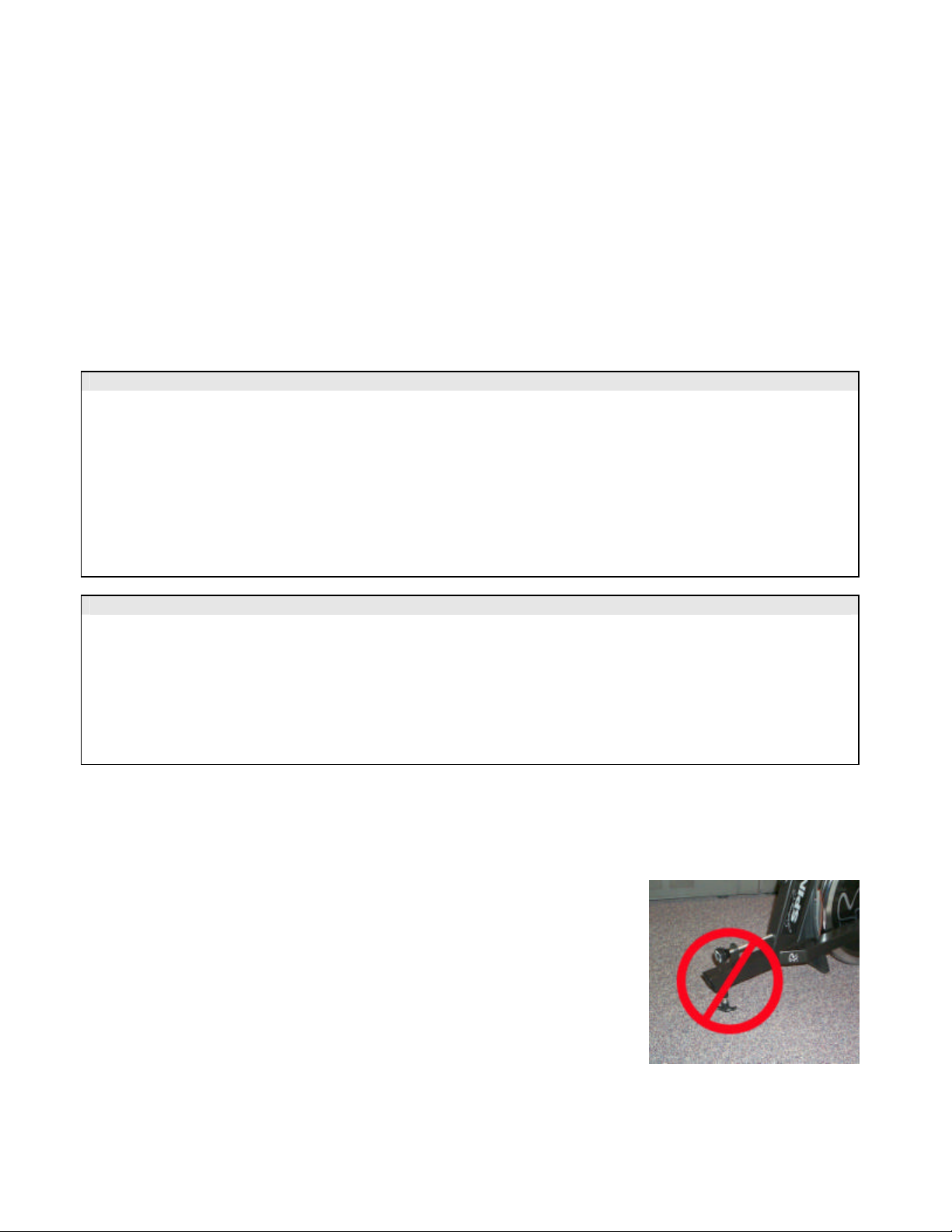
CAUTION: Damage to the bike during assembly is not covered as part of the
limited Star Trac warranty. Take care not to drop or lean the bike on the
handle bar pop pin. Carefully stand the bike up in the normal upright position
on a stable surface so it will not tip over during assembly.
Page 1 of 9
Page 3
Page 2 of 9Star T rac Product Support 800-503-1221
Assembly
Following these steps in order will minimize the build time and ensure proper assembly.
Note: Not all of the following procedures are performed on all models; Spinner ® Pro, Elite and NXT.
If the procedure is particular to that model only it will be noted as follows: (NXT Only) or (Pro/Elite Only)
or (NXT/Elite Only)
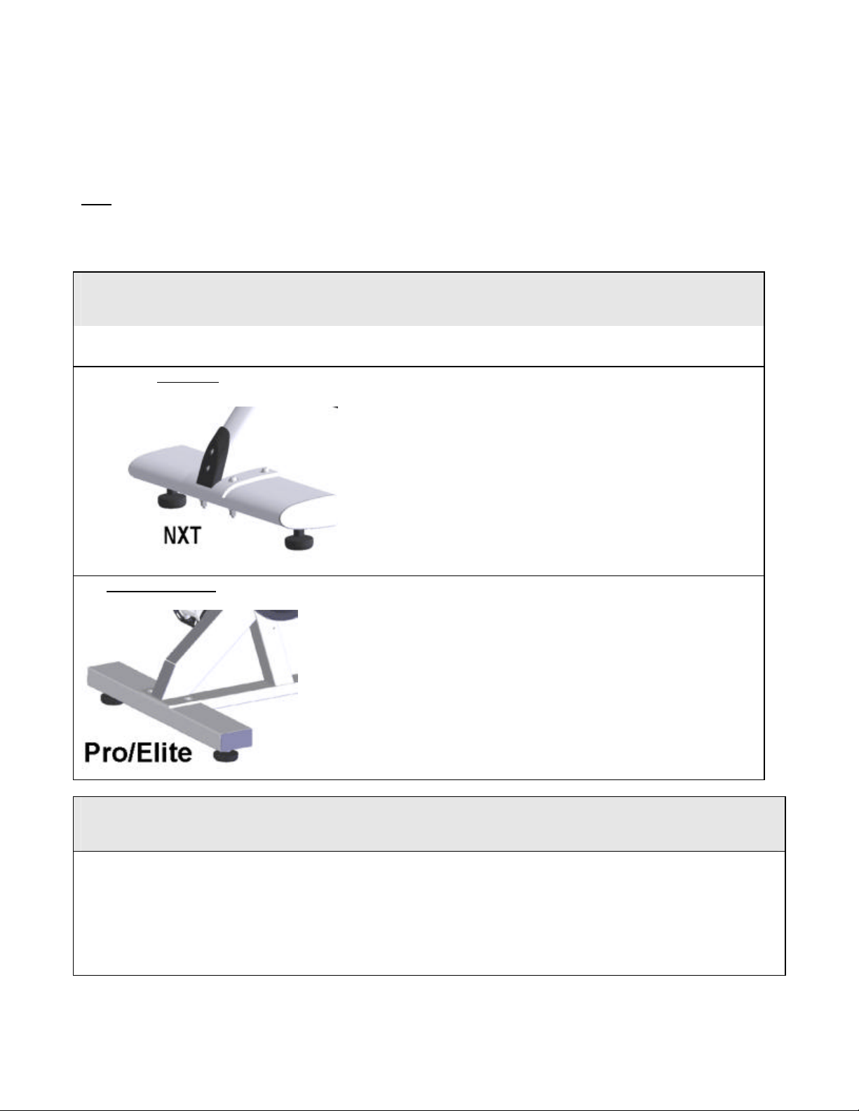
Installation of the Rear Leg Assembly
Lift up the rear of the bike frame and place the rear leg assembly in position under the frame, aligning the
holes in the leg with the holes in the frame.
NXT Only
Pro & Elite Only
1. Position the leg so the thicker end faces toward the front
of the bike
2. Using the 5mm hex wrench and a 13mm combination
wrench insert 2- M10X55mm (rear-most holes) and 2M10X65mm (front -most holes) button head screws, nuts
and washers (under bolt head and nut), to secure the
rear leg assembly to the frame. The nut should be on
the bottom of the bike and the head of the screw on the
top of the bike.
3. Tighten all hardware securely using a torque wrench to
85 Inch Pounds
1. Lift up the rear of the bike frame and place the rear leg
assembly in position under the frame, aligning the holes
in the leg with the holes in the frame.
2. Using the 5mm hex wrench and a 13mm combination
wrench insert 2- M10X55mm flat head screws, nuts and
washers to secure the rear leg assembly to the frame.
The nut should be on the bottom of the bike and the
head of the screw on the top of the bike.
Tighten all screws/nuts securely using a torque wrench to 85
Inch Pounds
Installation of the Front Leg Assembly
NOTE: The front foot assembly has wheels attached to the front edge. Be sure the wheels face forward when
installing the front leg assembly.
Stand the bike frame upright and gently tip the front of the bike up and position the front foot under the frame,
with the wheels facing forward.
Attach the front foot assembly to the frame, aligning the holes in the foot with the holes in the frame.
Page 2 of 9
Page 4
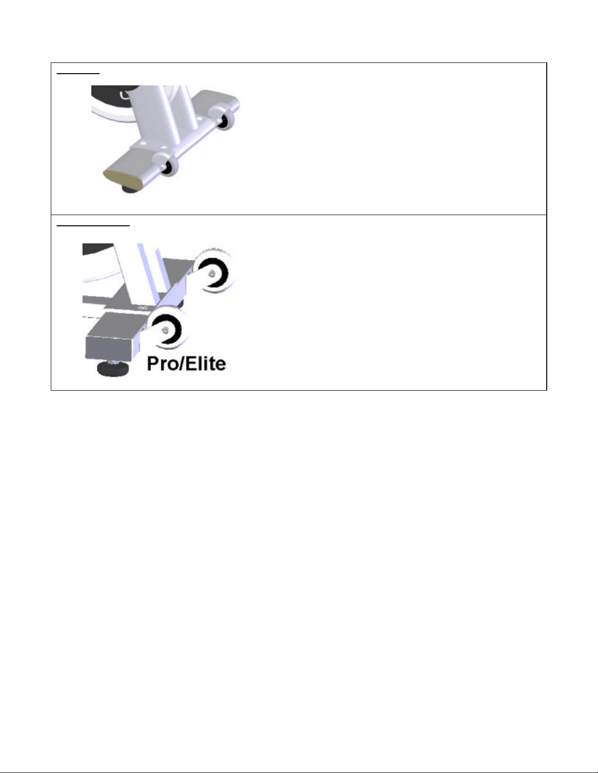
NXT Only
Pro & Elite Only
Page 3 of 9Star T rac Product Support 800-503-1221
1. Position the leg so the thicker end faces toward
the front of the bike
2. Using the 5mm hex wrench and a 13mm
combination wrench insert 2- M10X55mm (rearmost holes) and 2-M10X65mm (front -most holes)
button head screws, nuts and washers (under bolt
head and nut), to secure the rear leg assembly to
the frame. The nut should be on the bottom of the
bike and the head of the screw on the top of the
bike.
3. Tighten all hardware securely using a torque
wrench to 85 Inch Pounds
1) Using the 5mm hex wrench and a 13mm
combination wrench insert 2- M10X55mm flat
head screws, nuts and washers to secure the rear
leg assembly to the frame. The nut should be on
the bottom of the bike and the head of the screw
on the top of the bike.
2) Tighten all screws/nuts securely using a torque
wrench to 85 Inch Pounds
Position the bike on a flat surface and adjust the
leveling feet so the bike is stable.
Page 3 of 9
Page 5
Page 4 of 9Star T rac Product Support 800-503-1221
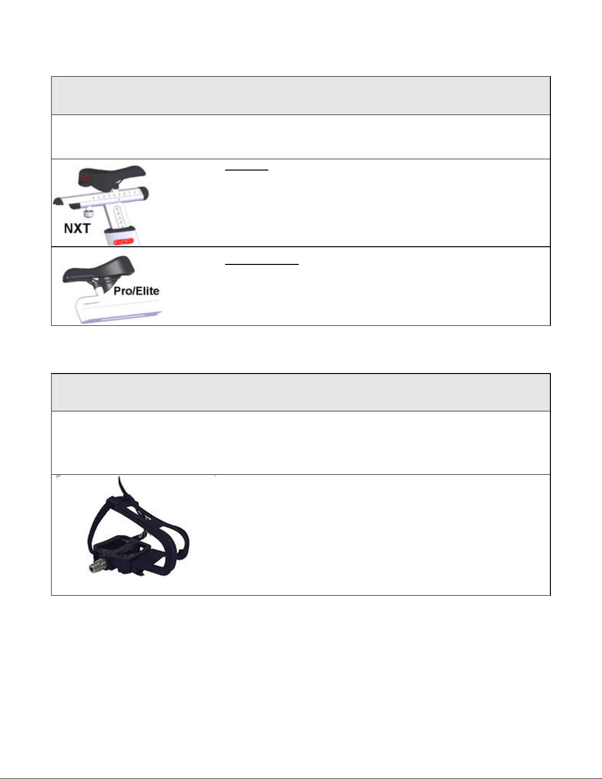
Installation of the Saddle and Seat Slider
1. Install the seat post into the frame and lower it to the lowest position and tighten the pop pin securely.
2. Slide the seat slide into the top of the seat post with the saddle pointed towards the front of the bike.
NXT Only
1. Rotate the seat slider lock knob as needed so that the slider clamp is in
alignment with the guide rail
2. There is a locking pin under the saddle that has to be pulled up as you
move the slider into position. Release the pin when the indicator is within
the 0 to 9 range.
3. Test the seat slide for proper operation and full travel.
Pro & Elite Only
1. Unscrew the seat slider pin far enough to allow the slider to pass over the
pin.
2. Tighten screw with the slider within the usable range.
3. Test the seat slide for proper operation and full travel.
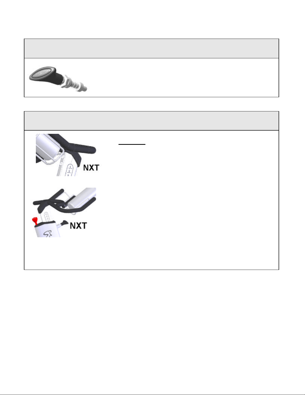
Installation of the Pedals
NOTE: The pedal shafts are marked “R” and “L”. Trying to install the pedals on the wrong side may damage
the pedal and the crank arm. Take caution to attach the pedals to the correct side of the bike (picture shown is
for Elite/NXT) .
1) Install the pedals on the pedal cranks using a 15mm open-end
wrench and tighten securely.
2) Turn the left pedal spindle counterclockwise when threading into
the left crank arm; turn the right pedal spindle clockwise when
threading into the right crank arm.
Page 4 of 9
Page 6
Page 5 of 9Star T rac Product Support 800-503-1221
ost
Installation of the Handlebar Pop Pin
1) Insert the pop pin into the front of the bike frame.
2) Hand-tighten the nut of the pop pin hand tight taking care not to
cross tread it.
3) Using a wrench tighten the pop pin assembly.
Assembly and Installation of the Handlebar and P
NXT Only
4) Positioning the handlebar post with the numbers 1 on top and
insert the handlebar into the handlebar sleeve locking it at number
4.
5) Slide the handlebar onto the handlebar post insert with the water
bottle holders facing forward and align the three screw holes.
6) Insert the socket head set screw into the handlebar but do not
tighten at this time.
7) Insert the 2 flat head screws into the handlebar but do not tighten
at this time.
8) Check for proper alignment then tighten the 2 flat head screws
using a 5mm hex wrench to 60 inch pounds.
9) Tighten the set screw to 60 inch pounds using a 4mm hex wrench.
10) Slide the handlebar post into the frame making sure the holes
face the front of the bike.
11) Allow the post to go into the frame all the way in to level 1 and
align the pop pin so it snaps into the hole then tighten the pop pin
and test for steadiness.
12) Loosen the pop pin and raise the handlebar to its highest position
number 10 and tighten the pop pin and test for steadiness.
Page 5 of 9
Page 7
Page 6 of 9Star T rac Product Support 800-503-1221
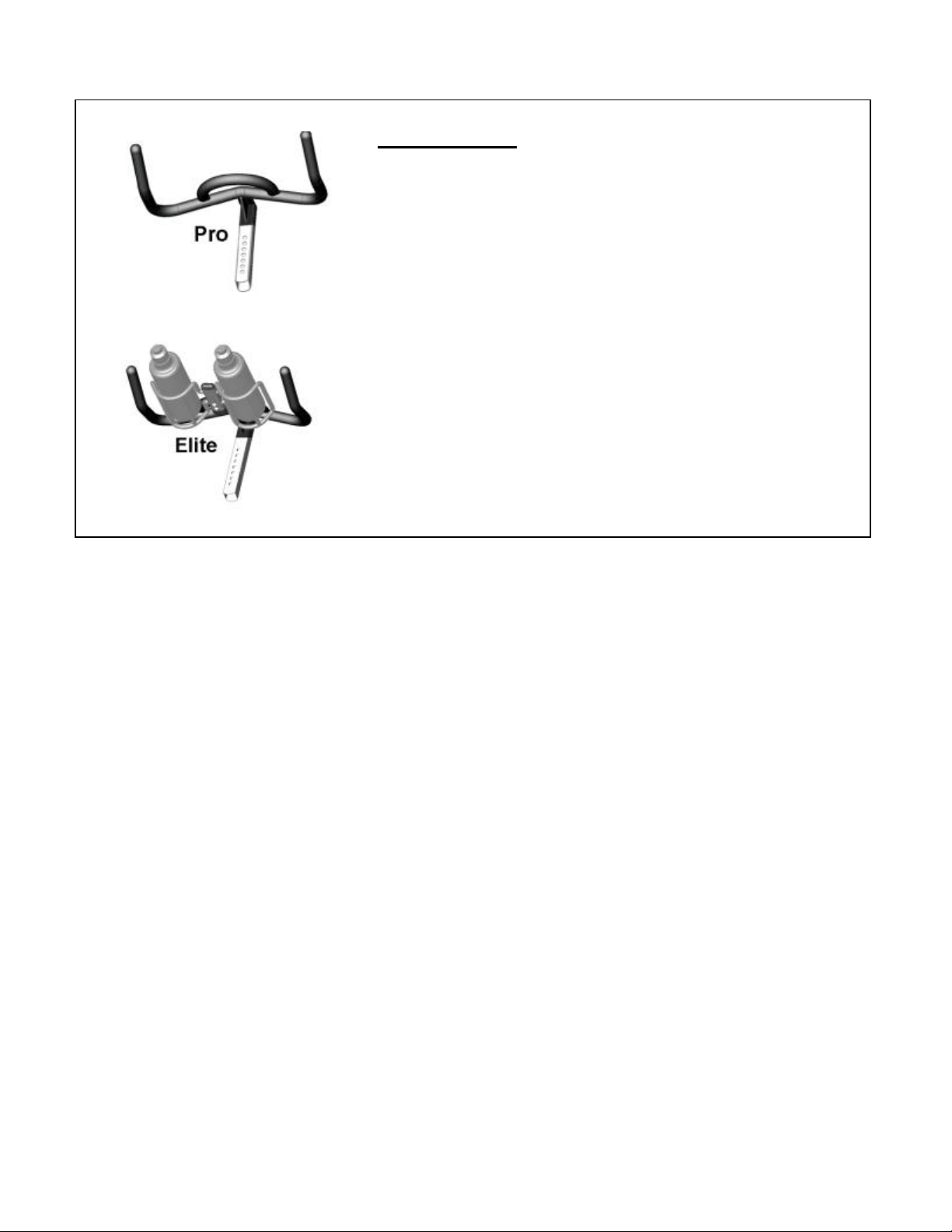
Pro & Elite Only
1) Slide the handlebar post into the frame making sure the holes
face the front of the bike.
2) Allow the post to go into the frame all the way in to level 1 and
align the pop pin so it snaps into the hole then tighten the pop pin
and test for steadiness.
3) Loosen the pop pin and raise the handlebar to its highest position
and tighten the pop pin and test for steadiness.
Page 6 of 9
Page 8

Page 7 of 9Star T rac Product Support 800-503-1221
Removing the decal protective covers
The bikes have protective clear decal covers to protect the decals from damage during
packaging and shipping. Using your fingers only, carefully peel off the protective covers after
assembly of the bike.
Testing the bike
Use this checklist to perform the bike test procedure to ensure the bike is operating properly.
¨ Recheck all bolts to make sure they are all tight ened to the proper torque specification and no parts were
left off the bike or are missing.
¨ Test the handlebar and seat post to make sure they move freely and you are able to lock in at different
positions.
¨ Check the seat to make sure it is level and tight and does not rotate around or tilt forward or backward.
Tighten and adjust as needed.
¨ Test the seat slide for easy movement front to rear and the ability to adjust it to different settings.
Testing the flywheel and brake mechanism.
CAUTION: The flywheel will continue to spin after you pedal and the crank arms and pedals will rotate with
the flywheel. Brake tension is adjustable by turning the red resistance knob in the front of the bike,
clockwise to tighten the brake and counterclockwise to loosen the brake. Pressing down on the knob will
apply the brake momentarily if you need to stop quickly.
¨ Adjust seat post and handlebar post to your comfort. Ride / test the bike for proper operation according to
the owner's manual.
¨ Pedal the bike at a moderate pace and test for proper and smooth resistance changes while varying the
amount of turns on the resistance knob.
¨ When the testing is complete tip the bike forward using the handlebars and roll it on a smoot h surface to the
final location. Check and adjust the leveling feet so the bike is stable.
Page 7 of 9
Page 9

Page 8 of 9Star T rac Product Support 800-503-1221
WEB SITE
http://support.startrac.com/
PHONE
800-503-1221
FAX
714-669-0739
EMAIL
SUPPORT@STARTRAC.COM
Copyright©, Star Trac 14410 Myford Road Irvine, CA 92606
New Spinner Bike Install Rev A PN 620-7493.doc
Page 8 of 9
 Loading...