


 Loading...
1 Port PS/2 USB VGA Server Remote Control IP KVM with Virtual Media and RS232
SV1108IPEXT
SV1108IPEXGB
SV1108IPEXEU
SV1108IPPOW
SV1108IPPWGB
SV1108IPPWEU
*actual product may vary from photos
DE: Bedienungsanleitung - de.startech.com
FR: Guide de l'utilisateur - fr.startech.com
ES: Guía del usuario - es.startech.com
IT: Guida per l'uso - it.startech.com
NL: Gebruiksaanwijzing - nl.startech.com
PT: Guia do usuário - pt.startech.com
For the most up-to-date information, please visit: www.startech.com
Manual Revision: 09/10/2013

FCC Compliance Statement
This equipment has been tested and found to comply with the limits for a Class A digital device, pursuant to Part 15 of the FCC Rules.These limits are designed to provide reasonable protection against harmful interference when the equipment is operated in a commercial environment. This equipment generates, uses, and can radiate radio frequency energy and, if not installed and used in accordance with the instruction manual, may cause harmful interference to radio communications. Operation of this equipment in a residential area is likely to cause harmful interferenceinwhichcasetheuserwillberequiredtocorrecttheinterferenceathisownexpense.
FCC Caution: Any changes or modifications not expressly approved by the party responsible for compliance could void the user’s authority to operate this equipment.
Warning: This is a class A product. In a domestic environment this product may cause radio interference in which case the user may be required to take adequate measures.
•Reorient or relocate the receiving antenna.
•Increase the separation between the equipment and receiver.
•Connect the equipment into an outlet on a circuit different from that to which the receiver is connected.
•Consult the dealer or an experienced radio/TV technician for help.
Use of Trademarks, Registered Trademarks, and other Protected Names and Symbols
This manual may make reference to trademarks, registered trademarks, and other protected names and/or symbols of third-party companies not related in any way to StarTech.com. Where they occur these references are for illustrative purposes only and do not represent an endorsement of a product or service by StarTech.com, or an endorsement of the product(s) to which this manual applies by the third-party company in question. Regardless of any direct acknowledgement elsewhere in the body of this document, StarTech.com hereby acknowledges that all trademarks, registered trademarks, service marks, and other protected names and/or symbols contained in this manual and related documents are the property of their respective holders.
Instruction Manual

Table of Contents |
|
Introduction............................................................................................. |
1 |
System Requirements ............................................................................................................................. |
1 |
Video ............................................................................................................................................................. |
2 |
Operating Systems ................................................................................................................................... |
2 |
Servers .......................................................................................................................................................... |
3 |
Package Contents...................................................................................................................................... |
3 |
Conventions ................................................................................................................................................ |
4 |
Terminology ................................................................................................................................................ |
4 |
Components............................................................................................ |
5 |
Front View..................................................................................................................................................... |
5 |
Rear View...................................................................................................................................................... |
6 |
Custom KVM Cables................................................................................ |
7 |
Custom Console Cable ........................................................................................................................... |
8 |
Hardware Setup.......................................................................................................................................... |
8 |
Rack Mounting........................................................................................ |
9 |
DIN Rail Mounting .................................................................................................................................... |
11 |
Installation .............................................................................................. |
12 |
Browser Login ......................................................................................... |
14 |
Logging In ................................................................................................................................................... |
15 |
Main Webpage Elements ....................................................................................................................... |
17 |
Administrative Function Icons ............................................................................................................. |
19 |
Exit Macro .................................................................................................................................................... |
20 |
Managing Power (SV1108IPPOW only).............................................................................................. |
21 |
Schedule (SV1108IPPOW only)............................................................................................................. |
25 |
Instruction Manual |
|
i

Auto Ping (SV1108IPPOW only)............................................................................................................ |
27 |
User Preferences......................................................................................................................................... |
29 |
Administration ....................................................................................... |
31 |
Device Information................................................................................................................................... |
32 |
Network......................................................................................................................................................... |
34 |
IP Address..................................................................................................................................................... |
35 |
SMTP Settings............................................................................................................................................. |
37 |
Syslog Server............................................................................................................................................... |
39 |
DDNS.............................................................................................................................................................. |
39 |
RADIUS Settings......................................................................................................................................... |
40 |
LDAP Settings............................................................................................................................................. |
42 |
Security .................................................................................................... |
45 |
Login String................................................................................................................................................. |
47 |
Account Policy ........................................................................................................................................... |
48 |
Encryption.................................................................................................................................................... |
50 |
Virtual Media .............................................................................................................................................. |
51 |
Private Certificate...................................................................................................................................... |
51 |
User Management .................................................................................................................................... |
54 |
Console Management ............................................................................................................................. |
57 |
Serial Console ............................................................................................................................................. |
58 |
Sessions......................................................................................................................................................... |
66 |
Customization............................................................................................................................................. |
66 |
Date/Time..................................................................................................................................................... |
69 |
Maintenance................................................................................................................................................ |
70 |
Firmware Upgrade..................................................................................................................................... |
71 |
Backup .......................................................................................................................................................... |
72 |
Restore .......................................................................................................................................................... |
72 |
Instruction Manual
ii

The WinClient Viewer ............................................................................ |
74 |
Navigation ................................................................................................................................................... |
75 |
The WinClient Control Panel ................................................................................................................. |
76 |
Hotkeys ......................................................................................................................................................... |
80 |
Macros .......................................................................................................................................................... |
82 |
Video Settings............................................................................................................................................. |
89 |
The Message Board................................................................................................................................... |
94 |
Virtual Media .............................................................................................................................................. |
97 |
The On-Screen Keyboard ...................................................................................................................... |
101 |
Mouse Pointer Type.................................................................................................................................. |
102 |
Automatic Mouse Synchronization (DynaSync) ............................................................................ |
103 |
Mac and Linux Considerations ............................................................................................................. |
103 |
Manual Mouse Synchronization .......................................................................................................... |
104 |
The JavaClient Viewer ........................................................................... |
107 |
Introduction ................................................................................................................................................ |
107 |
Navigation ................................................................................................................................................... |
108 |
The JavaClient Control Panel................................................................................................................. |
109 |
Hotkeys ......................................................................................................................................................... |
113 |
Macros........................................................................................................................................................... |
113 |
Message Board........................................................................................................................................... |
116 |
Virtual Media............................................................................................................................................... |
118 |
Zoom.............................................................................................................................................................. |
118 |
The On-Screen Keyboard........................................................................................................................ |
119 |
Mouse Pointer Type.................................................................................................................................. |
119 |
Control Panel Configuration ................................................................................................................. |
120 |
The Log File Screen ................................................................................ |
121 |
Instruction Manual
iii

The Log Server ........................................................................................ |
122 |
Installation ................................................................................................................................................... |
122 |
Starting Up .................................................................................................................................................. |
123 |
The Menu Bar ............................................................................................................................................ |
124 |
Configure ..................................................................................................................................................... |
124 |
Search ........................................................................................................................................................... |
125 |
Maintenance ............................................................................................................................................... |
127 |
The Log Server Main Screen.................................................................................................................. |
128 |
The List Panel ............................................................................................................................................. |
129 |
The Tick Panel ............................................................................................................................................. |
130 |
AP Operation............................................................................................................................................... |
131 |
The Windows Client AP ........................................................................................................................... |
131 |
The Administrator Utility ........................................................................................................................ |
136 |
The Java Client AP .................................................................................................................................... |
146 |
Appendix ................................................................................................. |
149 |
Safety Instructions .................................................................................................................................... |
149 |
Rack Mounting .......................................................................................................................................... |
151 |
IP Address Determination ...................................................................................................................... |
152 |
Browser.......................................................................................................................................................... |
153 |
AP Windows Client ................................................................................................................................... |
153 |
IPv6 ................................................................................................................................................................ |
154 |
Port Forwarding ........................................................................................................................................ |
155 |
Keyboard Emulation ................................................................................................................................ |
156 |
PPP Modem Operation............................................................................................................................ |
158 |
Trusted Certificates................................................................................................................................... |
160 |
Troubleshooting..................................................................................... |
165 |
General Operation..................................................................................................................................... |
165 |
Java................................................................................................................................................................. |
167 |
Sun Systems................................................................................................................................................. |
168 |
Instruction Manual |
|
iv

Mac Systems................................................................................................................................................ |
170 |
The Log Server............................................................................................................................................ |
170 |
Additional Mouse Synchronization Procedures............................................................................. |
171 |
Virtual Media Support ............................................................................................................................. |
173 |
Administrator Login Failure .................................................................................................................. |
174 |
Specifications.......................................................................................... |
175 |
Technical Support................................................................................... |
176 |
Warranty Information............................................................................ |
176 |
Instruction Manual
v

Introduction
The SV1108IPEXT/POW 1 Port Remote Control IP KVM Switch with Virtual Media lets you control a USB or PS/2 server remotely over a LAN or the Internet.
The 1 port KVM over IP includes all necessary KVM cables, and offers KVM control from the BIOS-level onward. Reboot, monitor the entire boot process, and interact with your connected system easily, while the integrated single-port power switch allows you to power the server on or off remotely. RS232 support also lets you connect to a serial console device via Telnet or SSH.
Virtual Media lets you execute files via USB from the remote console as if they were local to the connected server. Perfect for remote driver updates, patches, application or OS installation.
The Java-based browser utility ensures the IP remote control unit is compatible with many current web browsers, and almost any operating system on the market.
Multiple integrated security features ensure a reliable single port IP KVM connection, including password-protection, IP/MAC address filtering, external authentication (RADIUS, LDAP, LDAPS, Active Directory) and advanced encryption (56-bit DES, 168-bit 3DES, 256-bit AES, 128-bit RC4).
The integrated remote power switch (SV1108IPPOW only) lets you Power the server on or off remotely as necessary.
Backed by a StarTech.com 2-year warranty and free lifetime technical support.
System Requirements
Remote User Computers
Remote user computers (also referred to as client computers) are the ones the users log into the switch with from remote locations over the internet. The following equipment must be installed on these computers:
For best results we recommend that the computers used to access the switch have at least a P III 1 GHz processor, with their screen resolution set to 1024 x 768.
Browsers must support 128 bit SSL encryption.
For best results, a network transfer speed of at least 128 kbps is recommended.
For the Log Server, you must have the Microsoft Jet OLEDB 4.0 or higher driver installed.
For Safe Shutdown:
The computer must be running Windows (Windows 2000 or higher), or Linux.
The Safe Shutdown program (available by download from our website), must be installed and running on the computer.
Instruction Manual
1

Video
Only the following non-interlaced video signals are supported:
Resolution |
Refresh Rates |
640 x 480 |
60, 72, 75, 85, 90, 100, 120 |
720 x 400 |
70 |
800 x 600 |
56, 60, 72, 75, 85, 90, 100, 120 |
1024 x 768 |
60, 70, 75, 85, 90, 100 |
1152 x 864 |
60, 70, 75, 85 |
1280 x 720 |
60 |
1280 x 1024 |
60, 70, 75, 85 |
1600 x 1200 |
60 |
Operating Systems
Supported operating systems for remote user computers that log into the SV1108IPEXT/POW include Windows 2000 and higher, and other systems capable of running Sun’s Java Runtime Environment (JRE) 6, Update 3, or higher (Linux, Mac, Sun, etc.).
Browsers
Supported browsers for users that log into the SV1108IPEXT/POW include the following:
|
Browser |
Version |
|
|
Internet Explorer |
6 and higher |
|
Chrome |
Windows |
8.0 and higher |
|
3.5 and higher |
|||
Firefox |
Linux |
3.0 and higher |
|
Safari |
Windows |
4.0 and higher |
|
Opera |
Mac |
3.1 and higher |
|
|
|
10.0 and higher |
|
Mozilla |
Windows |
1.7 and higher |
|
Sun |
1.7 and higher |
||
|
|||
|
Netscape |
9.0 and higher |
Instruction Manual
2

Servers
Servers are the computers connected to the switch via KVM Cables. The following equipment must be installed on these servers:
A VGA, SVGA or multisync port
For USB KVM Cable Connections: a Type A USB port and USB host controller For PS/2 KVM Cable Connections: 6-pin Mini-DIN keyboard and mouse ports
Package Contents
SV1108IPEXT
•IP KVM Switch
•Console Cable
•PS/2 KVM Cable
•USB 2.0 Virtual Media Cable
•USB KVM Cable
•Rack Mount Kit
•Software CD
•Instruction Manual (on CD)
•Quick Start Guide
SV1108IPPOW
•IP KVM Switch
•Console Cable
•PS/2 KVM Cable
•USB 2.0 Virtual Media Cable
•USB KVM Cable
•Rack Mount Kit
•Software CD
•Instruction Manual (on CD)
•Quick Start Guide
Instruction Manual
3
Conventions
This manual uses the following conventions: Monospaced Indicates text that you should key in.
[ ] Indicates keys you should press. For example, [Enter] means to press the Enter key. If keys need to be chorded, they appear together in the same bracket with a plus sign between them: [Ctrl+Alt].
1. Numbered lists represent procedures with sequential steps.
 Bullet lists provide information, but do not involve sequential steps.
  Indicates selecting the option (on a menu or dialog box, for example)
Terminology
Throughout the manual we make reference to the terms Local and Remote in regard to the operators and equipment deployed in a SV1108IPEXT/POW installation. Depending on the point of view, users and servers can be considered Local under some circumstances, and Remote under others:
Switch’s Point of View
Remote users – We refer to a user as a Remote user when we think of him as someone who logs into the switch over the net from a location that is remote from the switch.
Local Console – The keyboard mouse and monitor connected directly to the switch.
Servers – The servers attached to the switch via custom KVM cables.
User’s Point of View
Local client users – We refer to a user as a Local client user when we think of him as sitting at his computer performing operations on the servers connected to the switch that is remote from him.
Remote servers – We refer to the servers as Remote servers when we think of them from the Local Client User’s point of view – since, although they are locally attached to the switch, they are remote from him.
When we describe the overall system architecture we are usually speaking from the switch’s point of view – in which case the users are considered remote. When we speak about operations users perform via the browser, viewers, and AP programs over the net, we are usually speaking from the user’s point of view – in which case the switch and the servers connected to it are considered remote.
Instruction Manual
4
Components
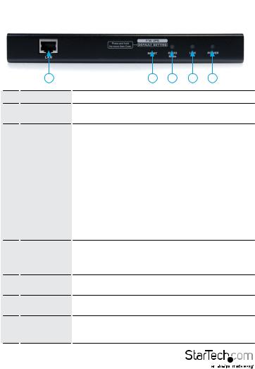
Front View
|
1 |
2 |
3 |
4 |
5 |
|
|
|
|
|
|
||
No. |
Component |
Description |
|
|
||
1 |
LAN Port |
The Cat 5e cable that connects the SV1108IPEXT/POW to |
||||
the LAN, WAN, or Internet plugs in here. |
||||||
|
|
|||||
|
|
1. Pressing and releasing this switch performs a |
||||
|
|
SV1108IPEXT/POW system reset. |
|
|||
|
|
2. Pressing and holding this switch for more than three |
||||
|
|
seconds returns the SV1108IPEXT/POW to its factory default |
||||
|
Firmware |
configuration settings. |
|
|||
|
3. Pressing and holding this switch while powering on the |
|||||
2 |
Upgrade/ |
|||||
switch returns the SV1108IPEXT/POW to its factory default |
||||||
|
Reset Switch |
|||||
|
firmware level. This operation should only be performed in |
|||||
|
|
|||||
|
|
the event of a firmware upgrade failure that results in the |
||||
|
|
device becoming inoperable. |
|
|||
|
|
NOTE: This switch is recessed and must be pushed with a |
||||
|
|
thin object - such as the end of a paper clip, or a |
||||
|
|
ballpoint pen. |
|
|
||
3 |
10/100 Mbps |
The LED lights ORANGE to indicate 10 Mbps data |
||||
LED |
transmission speed. It lights GREEN to indicate 100 Mbps |
|||||
|
data transmission speed. |
|
||||
|
|
|
||||
4 |
Link LED |
Flashes GREEN to indicate that a Client program is accessing |
||||
the device. |
|
|
||||
|
|
|
|
|||
5 |
Power LED |
Lights ORANGE when the SV1108IPEXT/POW is powered up |
||||
and ready to operate. |
|
|||||
|
|
|
||||
6 |
Power Outlet |
Lights ORANGE when the server attached to the |
||||
LED |
SV1108IPPOW’s power outlet is powered on |
|||||
|
(SV1108IPPOW only) |
|
||||
Instruction Manual
5
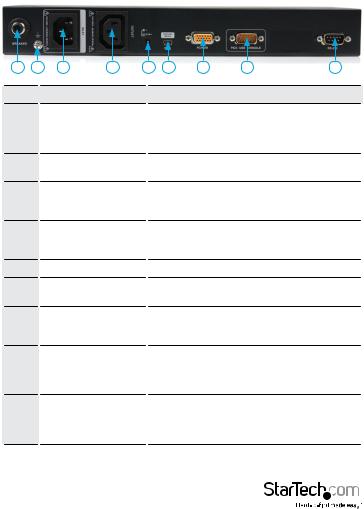
Rear View
1 |
2 |
3 |
4 |
5 |
6 |
7 |
8 |
9 |
No. |
|
|
Component |
|
|
|
Description |
|
|
|
|
|
|
As a safety measure, if there is an overcurrent |
|||
1 |
|
Circuit Breaker |
|
situation, the circuit breaker will trip. Press this |
||||
|
|
button to recover normal operation. (SV1108IPPOW |
||||||
|
|
|
|
|
||||
|
|
|
|
|
|
|
Only) |
|
2 |
|
Grounding Terminal |
|
The wire used to ground the unit connects here. |
||||
|
|
|
|
(SV1108IPPOW Only) |
|
|||
|
|
|
|
|
|
|
|
|
3 |
|
|
Power Inlet |
|
The power cord that connects the SV1108IPPOW |
|||
|
|
|
to an AC power source for power management |
|||||
|
|
|
|
|
functionality plugs in here. (SV1108IPPOW Only) |
|||
4 |
|
Power Outlet |
|
The power cord provided with the SV1108IPPOW |
||||
|
|
package that connects to the server for power |
||||||
|
|
|
|
|
management plugs in here. (SV1108IPPOW Only) |
|||
5 |
|
|
Power Jack |
|
|
The power adapter cable plugs in here. |
|
|
6 |
|
Virtual Media Port |
|
The cable that connects the SV1108IPEXT/POW to a |
||||
|
|
USB port on your server or KVM switch plugs in here. |
||||||
|
|
|
|
|
||||
7 |
|
|
PC/KVM Port |
|
The KVM cable provided with this package that links |
|||
|
|
|
the SV1108IPEXT/POW to your server / KVM switch |
|||||
|
|
|
|
|
|
|
plugs in here. |
|
|
|
|
|
|
The cable for the local console (keyboard, monitor, |
|||
8 |
|
|
Console Port |
|
and mouse) plugs in here. The console can use either |
|||
|
|
|
a PS/2 or USB keyboard and mouse. Each connector |
|||||
|
|
|
|
|
||||
|
|
|
|
|
is color coded and marked with an appropriate icon. |
|||
|
|
|
|
|
|
This serial port is provided for: |
|
|
9 |
|
|
RS-232 Port |
|
|
1. Serial console management |
|
|
|
|
|
|
|
or |
|
||
|
|
|
|
|
|
|
|
|
2. Out-of-band modem operation
Instruction Manual
6

Custom KVM Cables
1
2
No. Description
1 |
For use with PS/2 configuration servers or |
|
KVM switches. |
||
|
||
2 |
For use with USB configuration servers or |
|
KVM switches. |
||
|
NOTE: The advantage of using a USB cable is that it allows automatic locked-in mouse synchronization.
Instruction Manual
7
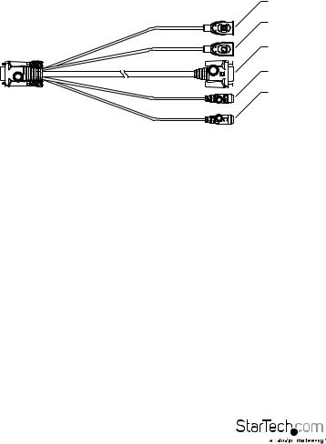
Custom Console Cable
USB Keyboard
USB Mouse
Video
PS/2 Keyboard
PS/2 Mouse
NOTE: You can use any combination of keyboard and mouse connections. For example, you can use a PS/2 keyboard with a USB mouse.
Hardware Setup
1.Important safety information regarding the placement of this device is provided on page 149. Please review it before proceeding.
2.Make sure that the power to any device that you connect to the installation has been turned off. You must unplug the power cords of any computers that have the Keyboard Power On function.
3.Any installation that does not follow the instructions in this guide may be hazardous.
Instruction Manual
8
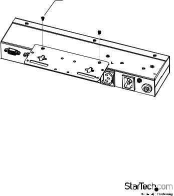
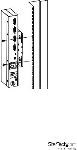
Rack Mounting
For convenience and flexibility, the SV1108IPEXT/POW can be mounted on a system rack.
To rack mount the unit do the following:
1.Remove the two original screws from the top/bottom of the unit (near the rear of the unit).
2.Using the screws provided with the rack mount kit, screw the mounting bracket into the SV1108IPEXT/POW – as shown in the diagram below:
M3 x 8
NOTE: The illustrations show the mounting bracket attached to the bottom of the unit; it can also be attached to the top.
Instruction Manual
9
3. Screw the bracket into any convenient location on the rack
NOTE: Rack screws are not provided. Use screws that are appropriate for your rack.
Instruction Manual
10
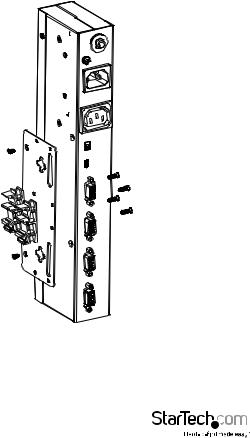
DIN Rail Mounting
To mount the SV1108IPEXT/POW on a DIN rail:
1.Screw the mounting bracket to the back of the SV1108IPEXT/POW as described in steps 1 and 2 of the wall mounting procedure.
2.Use the larger screws supplied with the Rack Mount Kit to screw the DIN rail brackets to the mounting bracket – as shown in the diagram, below:
3. Hang the unit on the DIN rail.
Instruction Manual
11

Installation
To install the SV1108IPEXT/POW, refer to the installation diagrams on the following pages (the numbers correspond to the numbers of the steps), and do the following:
1.Ground the unit using a grounding wire. (SV1108IPPOW Only)
2.Use the Console cable provided with this package to connect the SV1108IPEXT/ POW’s Console port, to the local console keyboard, monitor and mouse.
NOTE: 1. The Console cable comes with connectors for both PS/2 and USB mice and keyboards – use the ones appropriate for your installation.
2.You can use any combination of keyboard and mouse connections. For example, you can use a PS/2 keyboard with a USB mouse.
3.Use the KVM cable provided with this package to connect the SV1108IPEXT/POW’s PC port, to the keyboard, video and mouse ports of the server that you are installing.
4.(Optional) If you want to use the virtual media function, use the USB 2.0 Virtual Media Cable provided with this package to connect a USB port on the server to the SV1108IPEXT/POW’s Virtual Media port.
5.(Optional) If you want to connect a serial console device or modem, plug its cable into the RS-232 port.
6.Plug the LAN or WAN cable into the SV1108IPEXT/POW’s LAN port.
7.(SV1108IPPOW only) Use the outlet power cord provided with the package to connect the SV1108IPPOW’s Power Outlet to the attached server for
power management.
8.(SV1108IPPOW only) Use the power cord from the server to connect the SV1108IPPOW’s Power Inlet to an AC power source.
9.Plug the power adapter cable into the SV1108IPEXT/POW’s power jack, then plug the power adapter into an AC power source. This completes the hardware installation, and you are ready to start up.
NOTE: When starting up, be sure to first power on the SV1108IPEXT/POW, then power on the connected server.
Instruction Manual
12

6
|
9 |
Modem |
|
|
|
|
|
8 |
|
5 |
Serial Console |
|
|
Device |
|
|
|
|
(Router, Switch, |
|
|
|
Sunfire V100,....) |
1
7 4
3 2
Instruction Manual
13
1
2
Browser Login
The SV1108IPEXT/POW can be accessed either from an internet type browser, via Windows and Java application (AP) program, or by PPP modem dial-in. The next several chapters describe browser-based operations.
NOTE: Windows Vista/7 users who want to use the SV1108IPEXT/POW’s Virtual Media feature must run the internet browser as an Administrator.
Instruction Manual
14
Logging In
To operate the SV1108IPEXT/POW from an Internet browser, begin by logging in:
1.Open your browser and specify the IP address of the SV1108IPEXT/POW you want to access in the browser’s URL location bar.
NOTE: For security purposes, a login string may have been set by the administrator. If so, you must include a forward slash and the login string along with the IP address when you log in. For example:
192.168.0.60/SV1108IPEXT
If you don’t know the IP address and login string, ask your Administrator.
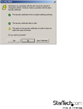
If you are the administrator, and are logging in for the first time, the various ways to determine the SV1108IPEXT/POW’s IP address are described in the Appendix on page 152. A Security Alert dialog box appears.
Accept the certificate – it can be trusted. If a second certificate appears, accept it as well.
Instruction Manual
15
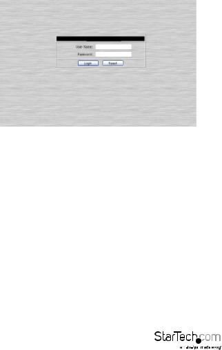
The SV1108IPEXT/POW login page appears:
3.Provide a valid Username and Password (set by the SV1108IPEXT/POW administrator), then click Login to continue.
NOTE:
1.If you are the administrator, and are logging in for the first time, use the default Username: administrator; and the default Password: password. For security purposes, we strongly recommend you remove these and give yourself a unique Username and Password.
2.If you supplied an invalid login, the authentication routine will return this message: Invalid Username or Password. Please try again. If you see this message, log in again being careful with the Username and Password.
Instruction Manual
16
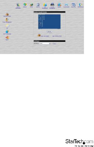
After you have successfully logged in, the SV1108IPEXT/POW Main Screen appears:
Main Webpage Elements
The Main page consists of user access icons arranged vertically down the left side; administrative function icons arranged across the top; a Remote Console Preview window with an icon to launch the Java or WinClient Viewer displayed in the center; and an Exit Macro list box just below the Remote Console Preview
NOTE: If a user doesn’t have permission to perform a particular activity, the icon for that activity doesn’t appear.
Instruction Manual
17
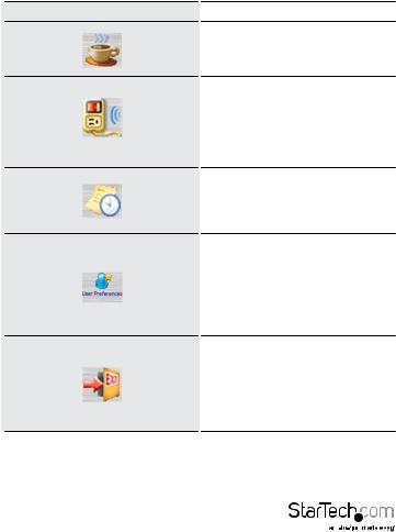
Utility Icons
The icons arranged down the left side perform the following functions:
Icon |
Purpose |
|
Remote Console: Clicking this icon |
|
closes whatever is displayed on the |
|
Main Screen, and brings back the |
|
Remote Console Preview. |
|
(SV1108IPPOW only) Power |
|
Management: If you have the proper |
|
permission, clicking this icon will bring |
|
up the SV1108IPPOW’s power control |
|
interface, allowing you to reset power |
|
over the network and use the Wake on |
|
LAN feature. |
|
Log: All the events that take place on |
|
the SV1108IPEXT/POW are recorded |
|
in a log file. If you have the proper |
|
permission, clicking this icon displays |
|
the contents of the log file. |
|
User Preferences: Click this icon to |
|
set up your own, individual, browsing |
|
environment. The switch stores a |
|
separate configuration record for |
|
each user profile, and sets up the |
|
browser configuration according to the |
|
Username that you key into the Login |
|
dialog box. |
|
Logout: Click this icon to log out and |
|
end your SV1108IPEXT/POW session. |
|
It is important to log out when you end |
|
your session. Otherwise, you must wait |
|
until the timeout setting has expired |
|
before the SV1108IPEXT/POW can be |
|
accessed again. |
Instruction Manual
18

Administrative Function Icons
The icons arranged horizontally across the top of the page are linked to the administration utilities, which are used to configure the SV1108IPEXT/POW.
Remote Console Preview
The main portion of the panel shows a snapshot of the server’s display.
Clicking Refresh updates the snapshot of the remote display.
The links that appear below the Refresh button depend on the browser you are using, and your User Preferences Viewer choice:
If you are logging in with a browser other than Windows Internet Explorer, a Java Applet Viewer icon (a steaming cup of coffee), and the link words “Open
Viewer” display.
If you are logging in with IE as your browser, and you chose Auto Detect as your Viewer choice (the default), The WinClient icon and the link words “Open Viewer” display.
If you are logging in with IE as your browser, and you chose Java as your Viewer choice a Java Applet Viewer icon (a steaming cup of coffee), and the link words “Open Viewer” display.
If you are logging in with IE as your browser, and you chose User Select as your Viewer choice, both the Java Applet Viewer and WinClient Viewer icons appear.
Click the appropriate link to have the viewer open the remote server’s display on your desktop.
NOTE: If you selected Auto Detect or Java, you can also open the remote server’s display by clicking on the snapshot window directly.
Instruction Manual
19
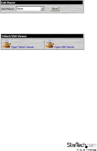
Exit Macro
The Exit Macro panel contains a dropdown list box of user created System macros:
You can select a macro from the list that will execute when exiting the remote server.
Telnet/SSH Viewer
If Serial Console Management has been enabled (see Serial Console, page 58), a Telnet/ SSH Viewer panel displays directly below the Exit Macro panel:
These viewers allow users to open a Telnet or SSH session to the SV1108IPEXT/POW from the browser. Depending on the user’s permissions, the Telnet Viewer link or SSH Viewer link, or both links are shown.
Click the appropriate link to have the viewer open the session.
Instruction Manual
20
Managing Power (SV1108IPPOW only)
To help you manage and control your entire data center environment, a built-in single-port power switch allows remote power management of a server/ installation connected locally to the SV1108IPPOW
If you have the proper permission, clicking this icon will bring up the SV1108IPPOW’s power control interface, allowing you to reset power over the network, use the Wake on LAN feature, schedule routines, use the Auto Ping function. These are all detailed in the sections that follow:
Instruction Manual
21
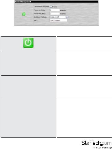
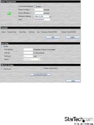
Power Management (SV1108IPPOW only)
This section lets you set up the power management for the SV1108IPPOW’s power switch.
The meanings of the field headings are given in the following table:
|
Click the Outlet icon to power operations |
|
|
on and off. A green outlet icon indicates |
|
|
that the power is currently On. |
|
|
If this option is enabled (there is a check |
|
|
in the checkbox), a dialog box comes up |
|
Confirmation Required |
asking you to confirm a power operation |
|
before it is performed. If it is disabled |
||
|
(there is no check in the checkbox), the |
|
|
operation is performed |
|
|
without confirmation. |
|
|
Sets the amount of time the |
|
|
SV1108IPPOW waits after the Power |
|
Power On Delay |
Button is clicked before it turns on the |
|
power to the outlet. |
||
|
||
|
NOTE: The default delay time is 0 |
|
|
seconds; the maximum is 999 seconds. |
|
|
Sets the amount of time the |
|
|
SV1108IPPOW waits after the Power |
|
|
Button is clicked before it turns off the |
|
|
power to the outlet. |
|
Power Off Delay |
For the System after AC Back option |
|
(see below), after the delay time expires, |
||
|
||
|
the SV1108IPPOW waits another fifteen |
|
|
seconds, then shuts the computer down. |
|
|
The default delay time is 15 seconds. The |
|
|
maximum delay time is 999 seconds. |
Instruction Manual
22

There are three choices for the Shutdown method. Drop down the list to select a choice. The meaning of each choice is described, below:
Wake on LAN: This is a Safe Shutdown and Restart option. If this is selected, when an Outlet is turned Off, the SV1108IPPOW first sends a message to the computer telling it to prepare for a shutdown; it then waits for the amount time set in the Power Off Delay field to give the OS time to close down before the computer is powered down to standby mode.
Likewise, when the Outlet is turned On, the SV1108IPPOW waits for the amount
time set in the Power On Delay field, Shutdown Method then sends an Ethernet message to
the computer connected to the Outlet telling the computer to turn itself On.
NOTE: For Safe Shutdown and Restart, the computer must be running Windows (98 or higher), or Linux, and the Safe Shutdown program (available by download from our website), must be installed and running on the computer.
System after AC Back: This is a Safe Shutdown and Restart option. If this is selected, when an Outlet is turned Off, the SV1108IPPOW first sends a message to the computer telling it to prepare for a shutdown; it then waits for the amount time set in the Power Off Delay field to
give the OS time to close down before the computer is powered down.
Instruction Manual
23
Loading...