

Page 1

1 Port PS/2 USB VGA Server Remote Control IP
KVM with Virtual Media and RS232
SV1108IPEXT
SV1108IPEXGB
SV1108IPEXEU
SV1108IPPOW
SV1108IPPWGB
SV1108IPPWEU
*actual product may vary from photos
DE: Bedienungsanleitung - de.startech.com
FR: Guide de l'utilisateur - fr.startech.com
ES: Guía del usuario - es.startech.com
IT: Guida per l'uso - it.startech.com
NL: Gebruiksaanwijzing - nl.startech.com
PT: Guia do usuário - pt.startech.com
For the most up-to-date information, please visit: www.startech.com
Manual Revision: 09/10/2013
Page 2

FCC Compliance Statement
This equipment has been tested and found to comply with the limits for a Class A digital device,
pursuant to Part 15 of the FCC Rules. These limits are designed to provide reasonable protection
against harmful interference when the equipment is operated in a commercial environment.
This equipment generates, uses, and can radiate radio frequency energy and, if not installed
and used in accordance with the instruction manual, may cause harmful interference to radio
communications. Operation of this equipment in a residential area is likely to cause harmful
interference in which case the user will be required to correct the interference at his own expense.
FCC Caution: Any changes or modications not expressly approved by the party responsible
for compliance could void the user’s authority to operate this equipment.
Warning: This is a class A product. In a domestic environment this product may cause radio
interference in which case the user may be required to take adequate measures.
• Reorient or relocate the receiving antenna.
• Increase the separation between the equipment and receiver.
• Connect the equipment into an outlet on a circuit dierent from that to which the receiver
is connected.
• Consult the dealer or an experienced radio/TV technician for help.
Use of Trademarks, Registered Trademarks, and other Protected Names and Symbols
This manual may make reference to trademarks, registered trademarks, and other
protected names and/or symbols of third-party companies not related in any way to
StarTech.com. Where they occur these references are for illustrative purposes only and do not
represent an endorsement of a product or service by StarTech.com, or an endorsement of the
product(s) to which this manual applies by the third-party company in question. Regardless
of any direct acknowledgement elsewhere in the body of this document, StarTech.com hereby
acknowledges that all trademarks, registered trademarks, service marks, and other protected
names and/or symbols contained in this manual and related documents are the property of
their respective holders.
Instruction Manual
Page 3

Table of Contents
Introduction ............................................................................................1
System Requirements ............................................................................................................................. 1
Video ............................................................................................................................................................. 2
Operating Systems .................................................................................................................................. 2
Servers .......................................................................................................................................................... 3
Package Contents ..................................................................................................................................... 3
Conventions ............................................................................................................................................... 4
Terminology ...............................................................................................................................................4
Components ............................................................................................5
Front View ....................................................................................................................................................5
Rear View ...................................................................................................................................................... 6
Custom KVM Cables ...............................................................................7
Custom Console Cable .......................................................................................................................... 8
Hardware Setup ......................................................................................................................................... 8
Rack Mounting .......................................................................................9
DIN Rail Mounting ................................................................................................................................... 11
Installation .............................................................................................12
Browser Login ........................................................................................14
Logging In ...................................................................................................................................................15
Main Webpage Elements ....................................................................................................................... 17
Administrative Function Icons .............................................................................................................19
Exit Macro ................................................................................................................................................... 20
Managing Power (SV1108IPPOW only) .............................................................................................21
Schedule (SV1108IPPOW only) ............................................................................................................ 25
Instruction Manual
i
Page 4

Auto Ping (SV1108IPPOW only) ........................................................................................................... 27
User Preferences ........................................................................................................................................29
Administration .......................................................................................31
Device Information ................................................................................................................................... 32
Network ........................................................................................................................................................ 34
IP Address .................................................................................................................................................... 35
SMTP Settings ............................................................................................................................................. 37
Syslog Server............................................................................................................................................... 39
DDNS ............................................................................................................................................................. 39
RADIUS Settings ........................................................................................................................................ 40
LDAP Settings ............................................................................................................................................. 42
Security ................................................................................................... 45
Login String ................................................................................................................................................. 47
Account Policy ........................................................................................................................................... 48
Encryption ................................................................................................................................................... 50
Virtual Media .............................................................................................................................................. 51
Private Certicate ...................................................................................................................................... 51
User Management ................................................................................................................................... 54
Console Management ............................................................................................................................ 57
Serial Console ............................................................................................................................................ 58
Sessions ........................................................................................................................................................ 66
Customization ............................................................................................................................................ 66
Date/Time .................................................................................................................................................... 69
Maintenance ............................................................................................................................................... 70
Firmware Upgrade ....................................................................................................................................71
Backup .......................................................................................................................................................... 72
Restore ......................................................................................................................................................... 72
Instruction Manual
ii
Page 5

The WinClient Viewer ............................................................................ 74
Navigation .................................................................................................................................................. 75
The WinClient Control Panel ................................................................................................................ 76
Hotkeys ........................................................................................................................................................ 80
Macros .......................................................................................................................................................... 82
Video Settings ............................................................................................................................................ 89
The Message Board .................................................................................................................................. 94
Virtual Media .............................................................................................................................................. 97
The On-Screen Keyboard ..................................................................................................................... 101
Mouse Pointer Type .................................................................................................................................. 102
Automatic Mouse Synchronization (DynaSync) ........................................................................... 103
Mac and Linux Considerations ............................................................................................................ 103
Manual Mouse Synchronization ......................................................................................................... 104
The JavaClient Viewer ...........................................................................107
Introduction ............................................................................................................................................... 107
Navigation .................................................................................................................................................. 108
The JavaClient Control Panel ................................................................................................................109
Hotkeys ........................................................................................................................................................ 113
Macros ........................................................................................................................................................... 113
Message Board ........................................................................................................................................... 116
Virtual Media ............................................................................................................................................... 118
Zoom ............................................................................................................................................................. 118
The On-Screen Keyboard ....................................................................................................................... 119
Mouse Pointer Type .................................................................................................................................. 119
Control Panel Conguration ................................................................................................................120
The Log File Screen ...............................................................................121
Instruction Manual
iii
Page 6

The Log Server .......................................................................................122
Installation .................................................................................................................................................. 122
Starting Up ................................................................................................................................................. 123
The Menu Bar ............................................................................................................................................ 124
Congure .................................................................................................................................................... 124
Search ........................................................................................................................................................... 125
Maintenance .............................................................................................................................................. 127
The Log Server Main Screen .................................................................................................................. 128
The List Panel ............................................................................................................................................. 129
The Tick Panel ............................................................................................................................................ 130
AP Operation .............................................................................................................................................. 131
The Windows Client AP ..........................................................................................................................131
The Administrator Utility ....................................................................................................................... 136
The Java Client AP .................................................................................................................................... 146
Appendix ................................................................................................149
Safety Instructions ................................................................................................................................... 149
Rack Mounting .......................................................................................................................................... 151
IP Address Determination ..................................................................................................................... 152
Browser ......................................................................................................................................................... 153
AP Windows Client ................................................................................................................................... 153
IPv6 ................................................................................................................................................................ 154
Port Forwarding ........................................................................................................................................ 155
Keyboard Emulation ............................................................................................................................... 156
PPP Modem Operation ........................................................................................................................... 158
Trusted Certicates ...................................................................................................................................160
Troubleshooting .....................................................................................165
General Operation .................................................................................................................................... 165
Java ................................................................................................................................................................. 167
Sun Systems ................................................................................................................................................ 168
Instruction Manual
iv
Page 7

Mac Systems ............................................................................................................................................... 170
The Log Server ........................................................................................................................................... 170
Additional Mouse Synchronization Procedures .............................................................................171
Virtual Media Support ............................................................................................................................ 173
Administrator Login Failure .................................................................................................................. 174
Specications ..........................................................................................175
Technical Support ..................................................................................176
Warranty Information ............................................................................176
Instruction Manual
v
Page 8

Introduction
The SV1108IPEXT/POW 1 Port Remote Control IP KVM Switch with Virtual Media lets
you control a USB or PS/2 server remotely over a LAN or the Internet.
The 1 port KVM over IP includes all necessary KVM cables, and oers KVM control from
the BIOS-level onward. Reboot, monitor the entire boot process, and interact with your
connected system easily, while the integrated single-port power switch allows you to
power the server on or o remotely. RS232 support also lets you connect to a serial
console device via Telnet or SSH.
Virtual Media lets you execute les via USB from the remote console as if they were
local to the connected server. Perfect for remote driver updates, patches, application or
OS installation.
The Java-based browser utility ensures the IP remote control unit is compatible with
many current web browsers, and almost any operating system on the market.
Multiple integrated security features ensure a reliable single port IP KVM connection,
including password-protection, IP/MAC address ltering, external authentication
(RADIUS, LDAP, LDAPS, Active Directory) and advanced encryption (56-bit DES, 168-bit
3DES, 256-bit AES, 128-bit RC4).
The integrated remote power switch (SV1108IPPOW only) lets you Power the server on
or o remotely as necessary.
Backed by a StarTech.com 2-year warranty and free lifetime technical support.
System Requirements
Remote User Computers
Remote user computers (also referred to as client computers) are the ones the users
log into the switch with from remote locations over the internet. The following
equipment must be installed on these computers:
For best results we recommend that the computers used to access the switch have
at least a P III 1 GHz processor, with their screen resolution set to 1024 x 768.
Browsers must support 128 bit SSL encryption.
For best results, a network transfer speed of at least 128 kbps is recommended.
For the Log Server, you must have the Microsoft Jet OLEDB 4.0 or higher
driver installed.
For Safe Shutdown:
The computer must be running Windows (Windows 2000 or higher), or Linux.
The Safe Shutdown program (available by download from our website), must be
installed and running on the computer.
Instruction Manual
1
Page 9

Video
Only the following non-interlaced video signals are supported:
Resolution Refresh Rates
640 x 480 60, 72, 75, 85, 90, 100, 120
720 x 400 70
800 x 600 56, 60, 72, 75, 85, 90, 100, 120
1024 x 768 60, 70, 75, 85, 90, 100
1152 x 864 60, 70, 75, 85
1280 x 720 60
1280 x 1024 60, 70, 75, 85
1600 x 1200 60
Operating Systems
Supported operating systems for remote user computers that log into the
SV1108IPEXT/POW include Windows 2000 and higher, and other systems capable of
running Sun’s Java Runtime Environment (JRE) 6, Update 3, or higher (Linux, Mac,
Sun, etc.).
Browsers
Supported browsers for users that log into the SV1108IPEXT/POW include the following:
Browser Version
Internet Explorer 6 and higher
Chrome
Firefox
Safari
Opera
Mozilla
Windows
Linux
Windows
Mac
Windows 1.7 and higher
Sun 1.7 and higher
Netscape 9.0 and higher
8.0 and higher
3.5 and higher
3.0 and higher
4.0 and higher
3.1 and higher
10.0 and higher
Instruction Manual
2
Page 10

Servers
Servers are the computers connected to the switch via KVM Cables. The following
equipment must be installed on these servers:
A VGA, SVGA or multisync port
For USB KVM Cable Connections: a Type A USB port and USB host controller
For PS/2 KVM Cable Connections: 6-pin Mini-DIN keyboard and mouse ports
Package Contents
SV1108IPEXT
• IP KVM Switch
• Console Cable
• PS/2 KVM Cable
• USB 2.0 Virtual Media Cable
• USB KVM Cable
• Rack Mount Kit
• Software CD
• Instruction Manual (on CD)
• Quick Start Guide
SV1108IPPOW
• IP KVM Switch
• Console Cable
• PS/2 KVM Cable
• USB 2.0 Virtual Media Cable
• USB KVM Cable
• Rack Mount Kit
• Software CD
• Instruction Manual (on CD)
• Quick Start Guide
Instruction Manual
3
Page 11

Conventions
This manual uses the following conventions:
Monospaced Indicates text that you should key in.
[ ] Indicates keys you should press. For example, [Enter] means to press the Enter
key. If keys need to be chorded, they appear together in the same bracket
with a plus sign between them: [Ctrl+Alt].
1. Numbered lists represent procedures with sequential steps.
Bullet lists provide information, but do not involve sequential steps.
Indicates selecting the option (on a menu or dialog box, for example)
Terminology
Throughout the manual we make reference to the terms Local and Remote in regard
to the operators and equipment deployed in a SV1108IPEXT/POW installation.
Depending on the point of view, users and servers can be considered Local under
some circumstances, and Remote under others:
Switch’s Point of View
Remote users – We refer to a user as a Remote user when we think of him as
someone who logs into the switch over the net from a location
that is remote from the switch.
Local Console – The keyboard mouse and monitor connected directly to
the switch.
Servers – The servers attached to the switch via custom KVM cables.
User’s Point of View
Local client users – We refer to a user as a Local client user when we think of
him as sitting at his computer performing operations on the
servers connected to the switch that is remote from him.
Remote servers – We refer to the servers as Remote servers when we think of
them from the Local Client User’s point of view – since,
although they are locally attached to the switch, they are
remote from him.
When we describe the overall system architecture we are usually speaking from the
switch’s point of view – in which case the users are considered remote. When we speak
about operations users perform via the browser, viewers, and AP programs over the
net, we are usually speaking from the user’s point of view – in which case the switch
and the servers connected to it are considered remote.
Instruction Manual
4
Page 12

Components
Front View
1
No. Component Description
1 LAN Port
Firmware
2
Upgrade/
Reset Switch
10/100 Mbps
3
4 Link LED
5 Power LED
6
LED
Power Outlet
LED
The Cat 5e cable that connects the SV1108IPEXT/POW to
the LAN, WAN, or Internet plugs in here.
1. Pressing and releasing this switch performs a
SV1108IPEXT/POW system reset.
2. Pressing and holding this switch for more than three
seconds returns the SV1108IPEXT/POW to its factory default
conguration settings.
3. Pressing and holding this switch while powering on the
switch returns the SV1108IPEXT/POW to its factory default
rmware level. This operation should only be performed in
the event of a rmware upgrade failure that results in the
device becoming inoperable.
NOTE: This switch is recessed and must be pushed with a
thin object - such as the end of a paper clip, or a
The LED lights ORANGE to indicate 10 Mbps data
transmission speed. It lights GREEN to indicate 100 Mbps
data transmission speed.
Flashes GREEN to indicate that a Client program is accessing
Lights ORANGE when the SV1108IPEXT/POW is powered up
and ready to operate.
Lights ORANGE when the server attached to the
SV1108IPPOW’s power outlet is powered on
(SV1108IPPOW only)
3
2
ballpoint pen.
the device.
4 5
Instruction Manual
5
Page 13

Rear View
3
4
521 6
7 8 9
No. Component Description
As a safety measure, if there is an overcurrent
1 Circuit Breaker
2 Grounding Terminal
3 Power Inlet
4 Power Outlet
5 Power Jack
6 Virtual Media Port
7 PC/KVM Port
8 Console Port
9 RS-232 Port
situation, the circuit breaker will trip. Press this
button to recover normal operation. (SV1108IPPOW
Only)
The wire used to ground the unit connects here.
(SV1108IPPOW Only)
The power cord that connects the SV1108IPPOW
to an AC power source for power management
functionality plugs in here. (SV1108IPPOW Only)
The power cord provided with the SV1108IPPOW
package that connects to the server for power
management plugs in here. (SV1108IPPOW Only)
The power adapter cable plugs in here.
The cable that connects the SV1108IPEXT/POW to a
USB port on your server or KVM switch plugs in here.
The KVM cable provided with this package that links
the SV1108IPEXT/POW to your server / KVM switch
plugs in here.
The cable for the local console (keyboard, monitor,
and mouse) plugs in here. The console can use either
a PS/2 or USB keyboard and mouse. Each connector
is color coded and marked with an appropriate icon.
This serial port is provided for:
1. Serial console management
or
2. Out-of-band modem operation
Instruction Manual
6
Page 14
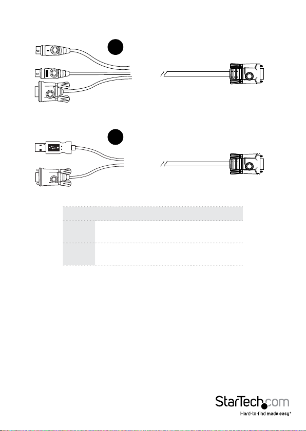
Custom KVM Cables
1
2
No. Description
For use with PS/2 conguration servers or
1
For use with USB conguration servers or
2
NOTE: The advantage of using a USB cable is that it allows automatic locked-in
mouse synchronization.
KVM switches.
KVM switches.
Instruction Manual
7
Page 15
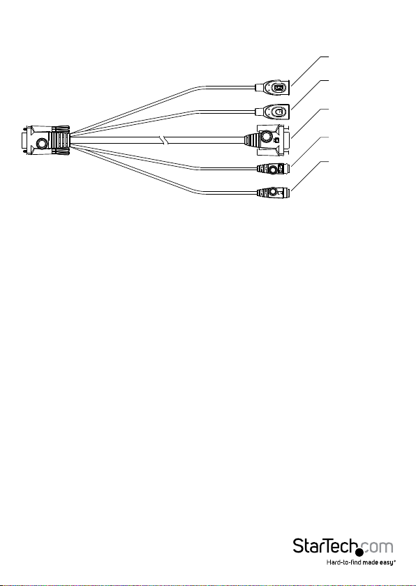
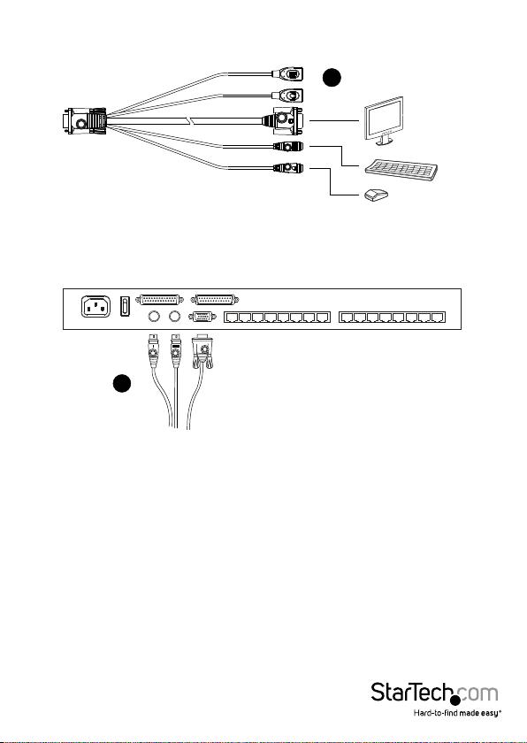
Custom Console Cable
USB Keyboard
USB Mouse
Video
PS/2 Keyboard
PS/2 Mouse
NOTE: You can use any combination of keyboard and mouse connections. For
example, you can use a PS/2 keyboard with a USB mouse.
Hardware Setup
1. Important safety information regarding the placement of this device is provided on
page 149. Please review it before proceeding.
2. Make sure that the power to any device that you connect to the installation has
been turned o. You must unplug the power cords of any computers that have the
Keyboard Power On function.
3. Any installation that does not follow the instructions in this guide may be hazardous.
Instruction Manual
8
Page 16
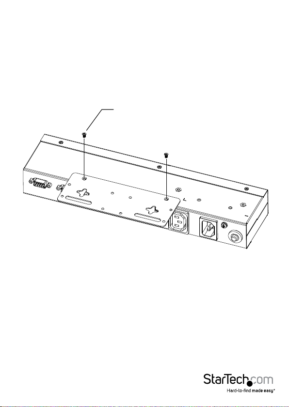
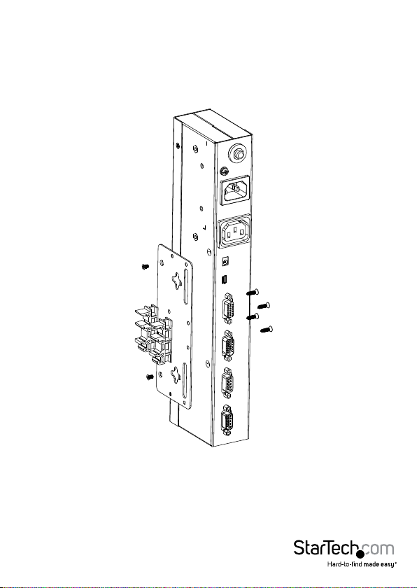
Rack Mounting
For convenience and exibility, the SV1108IPEXT/POW can be mounted on a
system rack.
To rack mount the unit do the following:
1. Remove the two original screws from the top/bottom of the unit (near the rear of
the unit).
2. Using the screws provided with the rack mount kit, screw the mounting bracket into
the SV1108IPEXT/POW – as shown in the diagram below:
M3 x 8
NOTE: The illustrations show the mounting bracket attached to the bottom of the unit;
it can also be attached to the top.
Instruction Manual
9
Page 17
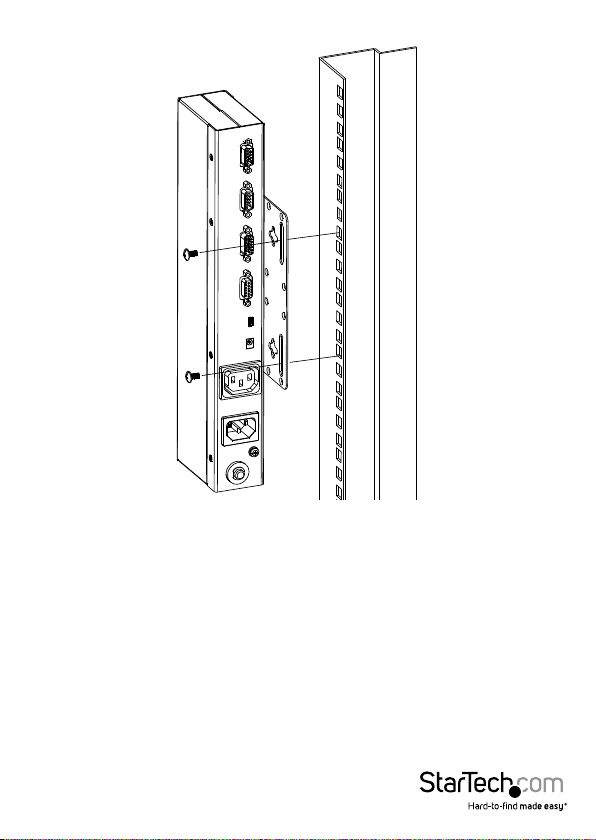
3. Screw the bracket into any convenient location on the rack
NOTE: Rack screws are not provided. Use screws that are appropriate for your rack.
Instruction Manual
10
Page 18
DIN Rail Mounting
To mount the SV1108IPEXT/POW on a DIN rail:
1. Screw the mounting bracket to the back of the SV1108IPEXT/POW as described in
steps 1 and 2 of the wall mounting procedure.
2. Use the larger screws supplied with the Rack Mount Kit to screw the DIN rail
brackets to the mounting bracket – as shown in the diagram, below:
3. Hang the unit on the DIN rail.
Instruction Manual
11
Page 19

Installation
To install the SV1108IPEXT/POW, refer to the installation diagrams on the following
pages (the numbers correspond to the numbers of the steps), and do the following:
1. Ground the unit using a grounding wire. (SV1108IPPOW Only)
2. Use the Console cable provided with this package to connect the SV1108IPEXT/
POW’s Console port, to the local console keyboard, monitor and mouse.
NOTE: 1. The Console cable comes with connectors for both PS/2 and USB mice and
keyboards – use the ones appropriate for your installation.
2. You can use any combination of keyboard and mouse connections. For
example, you can use a PS/2 keyboard with a USB mouse.
3. Use the KVM cable provided with this package to connect the SV1108IPEXT/POW’s
PC port, to the keyboard, video and mouse ports of the server that you are installing.
4. (Optional) If you want to use the virtual media function, use the USB 2.0 Virtual
Media Cable provided with this package to connect a USB port on the server to the
SV1108IPEXT/POW’s Virtual Media port.
5. (Optional) If you want to connect a serial console device or modem, plug its cable
into the RS-232 port.
6. Plug the LAN or WAN cable into the SV1108IPEXT/POW’s LAN port.
7. (SV1108IPPOW only) Use the outlet power cord provided with the package to
connect the SV1108IPPOW’s Power Outlet to the attached server for
power management.
8. (SV1108IPPOW only) Use the power cord from the server to connect the
SV1108IPPOW’s Power Inlet to an AC power source.
9. Plug the power adapter cable into the SV1108IPEXT/POW’s power jack, then
plug the power adapter into an AC power source. This completes the hardware
installation, and you are ready to start up.
NOTE: When starting up, be sure to rst power on the SV1108IPEXT/POW, then power
on the connected server.
Instruction Manual
12
Page 20
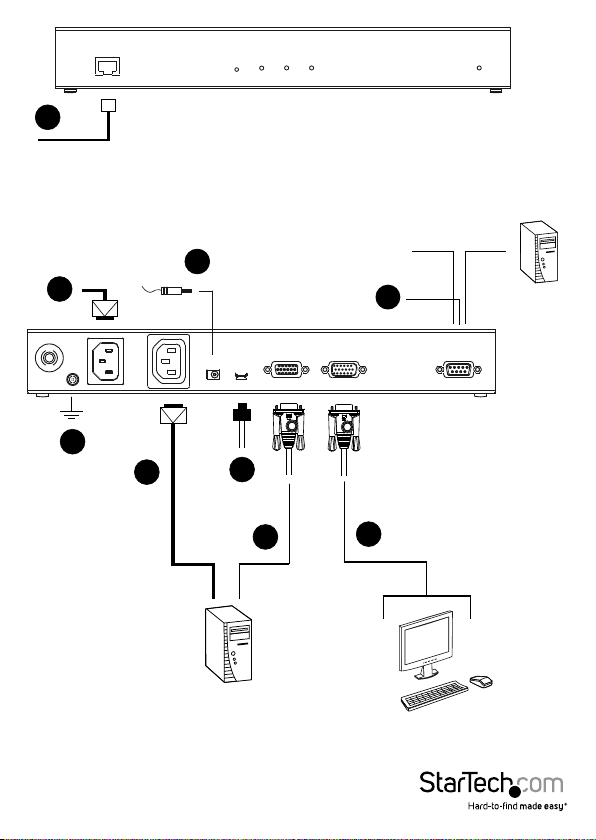
6
8
1
Instruction Manual
9
7
4
3
Modem
2
5
Serial Console
Device
(Router, Switch,
Sunre V100,....)
13
Page 21
1
2
Browser Login
The SV1108IPEXT/POW can be accessed either from an internet type browser, via
Windows and Java application (AP) program, or by PPP modem dial-in. The next
several chapters describe browser-based operations.
NOTE: Windows Vista/7 users who want to use the SV1108IPEXT/POW’s Virtual Media
feature must run the internet browser as an Administrator.
Instruction Manual
14
Page 22

Logging In
To operate the SV1108IPEXT/POW from an Internet browser, begin by logging in:
1. Open your browser and specify the IP address of the SV1108IPEXT/POW you want to
access in the browser’s URL location bar.
NOTE: For security purposes, a login string may have been set by the administrator.
If so, you must include a forward slash and the login string along with the IP
address when you log in. For example:
192.168.0.60/SV1108IPEXT
If you don’t know the IP address and login string, ask your Administrator.
If you are the administrator, and are logging in for the rst time, the various ways
to determine the SV1108IPEXT/POW’s IP address are described in the Appendix on
page 152. A Security Alert dialog box appears.
Accept the certicate – it can be trusted. If a second certicate appears, accept it
as well.
Instruction Manual
15
Page 23

The SV1108IPEXT/POW login page appears:
3. Provide a valid Username and Password (set by the SV1108IPEXT/POW
administrator), then click Login to continue.
NOTE:
1. If you are the administrator, and are logging in for the rst time, use the default
Username: administrator; and the default Password: password. For security
purposes, we strongly recommend you remove these and give yourself a unique
Username and Password.
2. If you supplied an invalid login, the authentication routine will return this message:
Invalid Username or Password. Please try again. If you see this message, log in again
being careful with the Username and Password.
Instruction Manual
16
Page 24

After you have successfully logged in, the SV1108IPEXT/POW Main Screen appears:
Main Webpage Elements
The Main page consists of user access icons arranged vertically down the left side;
administrative function icons arranged across the top; a Remote Console Preview
window with an icon to launch the Java or WinClient Viewer displayed in the center;
and an Exit Macro list box just below the Remote Console Preview
NOTE: If a user doesn’t have permission to perform a particular activity, the icon for
that activity doesn’t appear.
Instruction Manual
17
Page 25

Utility Icons
The icons arranged down the left side perform the following functions:
Icon Purpose
Remote Console: Clicking this icon
closes whatever is displayed on the
Main Screen, and brings back the
Remote Console Preview.
(SV1108IPPOW only) Power
Management: If you have the proper
permission, clicking this icon will bring
up the SV1108IPPOW’s power control
interface, allowing you to reset power
over the network and use the Wake on
LAN feature.
Log: All the events that take place on
the SV1108IPEXT/POW are recorded
in a log le. If you have the proper
permission, clicking this icon displays
the contents of the log le.
User Preferences: Click this icon to
set up your own, individual, browsing
environment. The switch stores a
separate conguration record for
each user prole, and sets up the
browser conguration according to the
Username that you key into the Login
dialog box.
Logout: Click this icon to log out and
end your SV1108IPEXT/POW session.
It is important to log out when you end
your session. Otherwise, you must wait
until the timeout setting has expired
before the SV1108IPEXT/POW can be
accessed again.
Instruction Manual
18
Page 26

Administrative Function Icons
The icons arranged horizontally across the top of the page are linked to the
administration utilities, which are used to congure the SV1108IPEXT/POW.
Remote Console Preview
The main portion of the panel shows a snapshot of the server’s display.
Clicking Refresh updates the snapshot of the remote display.
The links that appear below the Refresh button depend on the browser you are using,
and your User Preferences Viewer choice:
If you are logging in with a browser other than Windows Internet Explorer, a Java
Applet Viewer icon (a steaming cup of coee), and the link words “Open
Viewer” display.
If you are logging in with IE as your browser, and you chose Auto Detect as your
Viewer choice (the default), The WinClient icon and the link words “Open
Viewer” display.
If you are logging in with IE as your browser, and you chose Java as your Viewer
choice a Java Applet Viewer icon (a steaming cup of coee), and the link words
“Open Viewer” display.
If you are logging in with IE as your browser, and you chose User Select as your
Viewer choice, both the Java Applet Viewer and WinClient Viewer icons appear.
Click the appropriate link to have the viewer open the remote server’s display on your
desktop.
NOTE: If you selected Auto Detect or Java, you can also open the remote server’s
display by clicking on the snapshot window directly.
Instruction Manual
19
Page 27

Exit Macro
The Exit Macro panel contains a dropdown list box of user created System macros:
You can select a macro from the list that will execute when exiting the remote server.
Telnet/SSH Viewer
If Serial Console Management has been enabled (see Serial Console, page 58), a Telnet/
SSH Viewer panel displays directly below the Exit Macro panel:
These viewers allow users to open a Telnet or SSH session to the SV1108IPEXT/POW
from the browser. Depending on the user’s permissions, the Telnet Viewer link or SSH
Viewer link, or both links are shown.
Click the appropriate link to have the viewer open the session.
Instruction Manual
20
Page 28

Managing Power (SV1108IPPOW only)
To help you manage and control your entire data center environment, a built-in
single-port power switch allows remote power management of a server/ installation
connected locally to the SV1108IPPOW
If you have the proper permission, clicking this icon will bring up the SV1108IPPOW’s
power control interface, allowing you to reset power over the network, use the Wake
on LAN feature, schedule routines, use the Auto Ping function. These are all detailed in
the sections that follow:
Instruction Manual
21
Page 29

Power Management (SV1108IPPOW only)
This section lets you set up the power management for the SV1108IPPOW’s
power switch.
The meanings of the eld headings are given in the following table:
Click the Outlet icon to power operations
on and o. A green outlet icon indicates
that the power is currently On.
If this option is enabled (there is a check
in the checkbox), a dialog box comes up
Conrmation Required
asking you to conrm a power operation
before it is performed. If it is disabled
(there is no check in the checkbox), the
operation is performed
without conrmation.
Sets the amount of time the
SV1108IPPOW waits after the Power
Power On Delay
Button is clicked before it turns on the
power to the outlet.
NOTE: The default delay time is 0
seconds; the maximum is 999 seconds.
Sets the amount of time the
SV1108IPPOW waits after the Power
Button is clicked before it turns o the
power to the outlet.
Power O Delay
For the System after AC Back option
(see below), after the delay time expires,
the SV1108IPPOW waits another fteen
seconds, then shuts the computer down.
The default delay time is 15 seconds. The
maximum delay time is 999 seconds.
Instruction Manual
22
Page 30

Shutdown Method
There are three choices for the
Shutdown method. Drop down the list
to select a choice. The meaning of each
choice is described, below:
Wake on LAN: This is a Safe Shutdown
and Restart option. If this is selected,
when an Outlet is turned O, the
SV1108IPPOW rst sends a message to
the computer telling it to prepare for a
shutdown; it then waits for the amount
time set in the Power O Delay eld to
give the OS time to close down before
the computer is powered down to
standby mode.
Likewise, when the Outlet is turned On,
the SV1108IPPOW waits for the amount
time set in the Power On Delay eld,
then sends an Ethernet message to
the computer connected to the Outlet
telling the computer to turn itself On.
NOTE: For Safe Shutdown and Restart,
the computer must be running Windows
(98 or higher), or Linux, and the Safe
Shutdown program (available by
download from our website), must be
installed and running on the computer.
System after AC Back: This is a Safe
Shutdown and Restart option. If this is
selected, when an Outlet is turned O,
the SV1108IPPOW rst sends a message
to the computer telling it to prepare for
a shutdown; it then waits for the amount
time set in the Power O Delay eld to
give the OS time to close down before
the computer is powered down.
Instruction Manual
23
Page 31

Shutdown Method (Continued)
MAC
When the Outlet is turned On, the
SV1108IPPOW waits for the amount
time set in the Power On Delay eld,
then sends power to the server. When
the server receives the power, it turns
itself on.
NOTE: For Safe Shutdown and Reboot,
the computer must be running Windows
(98 or higher), or Linux, and the Safe
Shutdown program (available by
download from our website), must be
installed and running on the computer.
Kill the Power: If this option is selected,
the SV1108IPPOW waits for the amount
time set in the Power O Delay eld,
and then turns the Outlet’s power O.
Turning the power o performs a cold
(non-safe) shutdown.
In order to use either of the Safe
Shutdown methods the MAC address of
the computer connected to the outlet
must be lled in here.
Instruction Manual
24
Page 32

Schedule (SV1108IPPOW only)
Clicking the Add button in the Schedule section brings up a page that lets you set up a
scheduled power On/O conguration for the selected outlet:
NOTE: Since the SV1108IPPOW has no RTC (real time clock) circuit, the unit will get
time from the NTP server or from the client PC (sync time from client PC after a system
reset or losing power).
The meanings of the eld headings are given in the table, below:
Heading Meaning
Drop down the list to select whether
Routine Type
Week Day
Date
the scheduled power conguration
should take place just Once, or on a
Daily, Weekly, or Monthly basis.
This eld only becomes active if you
choose Weekly as the routine type. If
you choose Weekly, drop down the list
to choose which day of the week you
want the power management routine
to take place on.
This eld only becomes active if you
choose Monthly as the routine type. If
you choose Monthly, drop down the list
to choose which day of the month you
want the power management routine
to take place on
Instruction Manual
25
Page 33

Heading Meaning
If you want to limit the power
management routine to a particular
Start Date
time period, either click the calendar
icon to select the date that the routine
will start at, or key in a start date using
the YYYY-MM-DD format
If you want to limit the power
management routine to a particular
End Date
time period, either click the calendar
icon to select the date that the routine
will end at, or key in an end date using
the YYYY-MM-DD format
Key in the time of day you want the
shutdown to take place using the
HH:MM format.
Shutdown Time
If you want to temporarily suspend
this function without deleting the
entry, click to put a check in the Disable
checkbox at the right of this eld.
You can reinstate the function by
unchecking the checkbox.
Key in the time of day you want the
restart to take place using the HH:MM
Restart Time
If you want to temporarily suspend
this function without deleting the
entry, click to put a check in the Disable
checkbox at the right of this eld.
You can reinstate the function by
unchecking the checkbox.
For added exibility, you can use this
eld to rene the Daily, Weekly, and
Every
Monthly routines. For example, if you
chose Daily as your routine type, you
could have the routine take place every
3 days (instead of every day), by keying a
3 in this eld.
format.
Instruction Manual
26
Page 34

After you have made your schedule settings, click Add. The schedule is summarized in
the list at the bottom of the panel. To remove the outlet’s schedule, select it in the list
and click Delete.
Auto Ping (SV1108IPPOW only)
The section allows you to use an ICMP ping command to check if the attached device
is functioning properly. This function is detailed in the following table:
Instruction Manual
Enable
Ping Address
Interval
Fail Count
Put a check in the checkbox to enable
this function.
Enter the IP address of the device to be
be pinged in this eld.
This eld sets how often the specied
device is pinged, in second intervals.
Enter a value between 1 and 255.
This eld sets how many times the
device is allowed to fail to respond to
the ping before an action is taken (see
below). Enter a value between 1 and 99.
27
Page 35

This eld sets what action is taken if the
device fails to respond to a specied
number of pings. Select one of the
following actions from the
drop-down menu:
Send email: This sends an email
using the SMTP server setting. For this
function to work, you must also enable
Action
reports from the SMTP server.
Outlet Power O/On: This resets the
power at the SV1108IPPOW’s
power outlet.
NOTE: This action must be conrmed
before saving.
No action: Select this option to do
nothing if the specied device fails
to respond.
NOTE: If Auto Ping fails, after power on, the SV1108IPEXT/POW waits ve
minutes before
Instruction Manual
28
Page 36

User Preferences
The User Preferences page allows the user to set three parameters: Viewer, Language,
and Password:
Instruction Manual
29
Page 37

The page settings are explained in the following table:
Setting Function
You can choose which viewer is used
Auto Detect will select the appropriate
viewer based on the web browser used;
WinClient for Windows Internet Explorer;
Java Client for other web browsers
Viewer
Java will open the Java based viewer
regardless of the web browser
User Select lets IE users bypass the Auto
Detect choice and choose for themselves
whether to use the WinClient or Java
Applet Viewer. After making your choice,
click Apply. Selects the language that the
interface displays in. Drop down the list
Selecting Auto causes the SV1108IPEXT/
POW to display the pages in the same
language that the browser is set to.
NOTE: If your browser is set to a non-
supported language, the SV1108IPEXT/
Language
POW looks to what your server’s
operating system is set to. If the
operating system is set to a supported
language it will use that language to
display its pages. If the operating system
is set to a non-supported language, the
SV1108IPEXT/POW defaults to English.
After making your choice, click Apply.
To change your password, key the new
password into the New Password input
box; key the exact same characters into
Change Password
the Conrm New Password input box;
then click Change Password to set the
when accessing a server:
(Firefox, etc.).
being used.
to make your selection.
new password.
Instruction Manual
30
Page 38

Administration
Introduction
The administration utilities, represented by the icons located across the top of the
SV1108IPEXT/POW web page, are used to congure the SV1108IPEXT/POW’s
operating environment.
This chapter discusses each of them in turn.
NOTE:
1. As you make your conguration changes in each dialog box, click Apply to
save them.
2. Some conguration changes only take eect after a SV1108IPEXT/POW reset. For
those changes, a check is automatically put in the Reset on Exit box. To have the
changes take eect, log out and then log back in again.
3. If you don’t have Conguration privileges, the Administration conguration dialogs
are not available.
Instruction Manual
31
Page 39

Device Information
The Device Information page is the rst of the Administration pages, and provides
information about the SV1108IPEXT/POW’s status.
SV1108IPEXT
An explanation of each of the elds is given in the table below:
Field Explanation
To make it easier to manage installations
that have more than one SV1108IPEXT/
Device Name
MAC Address
POW, each one can be given a name.
To assign a name for the SV1108IPEXT/
POW, key in one of your choosing here
(16 characters max.), then click Apply.
The SV1108IPEXT/POW’s MAC Address
displays here.
Instruction Manual
32
Page 40

Firmware Version
IPV4 Address
DNS
IPV6 Address
Indicates the SV1108IPEXT/POW’s
current rmware version level. New
versions of the SV1108IPEXT/POW’s
rmware can be downloaded from our
website as they become available. You
can reference this number to see if there
are newer versions available on
the website.
Displays the SV1108IPEXT/POW’s
Internet Protocol Version 4 (32 bit)
address (in the legacy format).
The IP address of the Domain
Name Server.
Displays the SV1108IPEXT/POW’s
Internet Protocol Version 6 (128 bit)
address (in the new format).
Instruction Manual
33
Page 41

Network
The Network dialog is used to specify the SV1108IPEXT/POW’s network environment.
Service Ports
If a rewall is being used, the Administrator can specify the port numbers that the
rewall will allow (and set the rewall accordingly). If a port other than the default is
set, users must specify the port number as part of the IP address when they log in. If
not, an invalid port number (or no port number) is specied, the SV1108IPEXT/POW
will not be found.
An explanation of the elds is given in the table below:
Field Explanation
HTTP
HTTPS
Telnet Port
The port number for a browser login.
The default is 80.
The port number for a secure browser
login. The default is 443.
The port for Telnet access. The default
is 23.
Instruction Manual
34
Page 42

This is the port number for connecting
Program
Virtual Media
SSH Port
NOTE:
1. Valid entries for all of the Service Ports are from 1–65535.
2. The service ports cannot have the same value. You must set a dierent value for
each one.
3. If there is no rewall (on an Intranet, for example), it doesn’t matter what these
numbers are set to, since they have no eect.
to the SV1108IPEXT/POW from the
Windows Client and Java Applet
Viewers, and from the Windows and
Java AP programs. The default is 9000.
This is the port number used for data
transfer using the SV1108IPEXT/POW’s
virtual media feature. Valid entries are
from 1–65535. The default is 9003.
The port for SSH access. The default is
22.
IP Address
The SV1108IPEXT/POW can either have its IP address assigned dynamically at bootup
(DHCP), or it can be given a xed IP address.
For dynamic IP address assignment, select the Obtain an IP address automatically, radio
button. (This is the default setting.)
To specify a xed IP address, select the Set IP address manually, radio button and ll in
the IP address.
NOTE:
1. If you choose Obtain IP address automatically, when the switch startsup it waits to
get its IP address from the DHCP server. If it hasn’t obtained the address after one
minute, it automatically reverts to its factory default IP address (192.168.0.60.)
2. If the SV1108IPEXT/POW is on a network that uses DHCP to assign network
addresses, and you need to ascertain its IP address, see IP Address Determination,
page 152, for information.
Instruction Manual
35
Page 43

DNS Server
The SV1108IPEXT/POW can either have its DNS server address assigned automatically,
or a xed address can be specied.
For automatic DNS Server address assignment, select the Obtain DNS server
address automatically, radio button.
To specify a xed address, select the Use the following DNS server address, radio
button and ll in the required information.
NOTE: Specifying at the alternate DNS Server address is optional.
Network Transfer Rate
This setting allows you to tailor the size of the data transfer stream to match network
trac conditions by setting the rate at which the SV1108IPEXT/POW transfers data to
remote computers. The range is from 4–99999 Kilobytes per second (KBps).
Finishing Up
After making any network changes, be sure Reset on exit on the Customization page
has been enabled (there is a check in the checkbox), before logging out. This allows
network changes to take eect without having to power the SV1108IPEXT/POW o
and on.
ANMS (Advanced Network Management)
The Advanced Network Management Settings page allows you to set up login
authentication and authorization management from external sources. It is divided into
several sections, each of which is described in the sections that follow.
IP Installer
The IP Installer is an external Windows-based utility for assigning IP addresses to the
SV1108IPEXT/POW.
Click one of the radio buttons to select Enable, View Only, or Disable for the IP Installer
utility.
NOTE:
1. If you select View Only, you will be able to see the SV1108IPEXT/POW in the IP
Installer’s Device List, but you will not be able to change the IP address.
2. For security, we strongly recommend that you set this to View Only or Disable after
using it.
Instruction Manual
36
Page 44

SMTP Settings
To have the SV1108IPEXT/POW email reports from the SMTP server to you, do
the following:
1. Enable the Enable report from the following SMTP server, and key in the IP address of
your SMTP server.
2. If your server requires authentication, put a check in the Server requires
authentication checkbox, and key in the appropriate account information in the
Account Name and Password elds.
3. Key in the email address of where the report is being sent from in the From eld.
NOTE:
1. Only one email address is allowed in the From eld, and it cannot exceed
64 Bytes.
2. 1 Byte = 1 English alphanumeric character.
4. Key in the email address (addresses) of where you want the SMTP reports sent to in
the To eld.
NOTE:
1. If you are sending the report to more than one email address, separate the
addresses with a semicolon. The total cannot exceed 256 Bytes.
2. 1 Byte = 1 English alphanumeric character.
5. Select the report options you would like sent. Choices include: Report IP address,
Report system reboot, Report user login and Report user logout.
Instruction Manual
37
Page 45

Log Server
Important transactions that occur on the SV1108IPEXT/POW, such as logins and
internal status messages, are kept in an automatically generated log le
Specify the MAC address of the computer that the Log Server runs on in the MAC
address eld.
Specify the port used by the computer that the Log Server runs on to listen for log
details in the Port eld. The valid port range is 1–65535. The default port number
is 9001.
NOTE: The port number must dierent than the one used for the Program port
SNMP Server
To be notied of SNMP trap events, do the following:
1. Check Enable SNMP Agent.
2. Key in the IP address and the port number of the computer to be notied of SNMP
trap events. The valid port range is 1-65535.
NOTE: The following SNMP trap events are sent: System Power On, Login Failure, and
System Reset.
Instruction Manual
38
Page 46

Syslog Server
To record all the events that take place on the SV1108IPEXT/POW and write them to a
Syslog server, do the following:
1. Check Enable.
2. Key in the IP address and the port number of the Syslog server. The valid port range
is 1-65535.
DDNS
DDNS allows the mapping of a dynamic IP address assigned by a DHCP server to a
hostname. To provide DDNS capability for the SV1108IPEXT/POW, do the following:
1. Check Enable.
2. Enter the hostname that you registered with your DDNS service provider.
3. Drop down the list to select the DDNS service you are registered with.
4. Key in the Username and Password that authenticates you with your DDNS service.
5. If the SV1108IPEXT/POW’s IP address changes, it must update the DDNS server so
that the new address is properly associated with its hostname. If it fails to update
the DDNS server, it must try again at a later time. Key in the amount of time (in
hours) to wait before trying to update the DHCP server again.
Instruction Manual
39
Page 47

Disable Local Authentication
Selecting this option will disable login authentication locally on the SV1108IPEXT/POW.
The switch can only be accessed using LDAP, LDAPS, MS Active Directory, RADIUS or CC
Management authentication.
RADIUS Settings
To allow authentication and authorization for the SV1108IPEXT/POW through a
RADIUS server, do the following:
1. Check Enable.
2. Fill in the IP addresses and port numbers for the Preferred and Alternate
RADIUS servers.
3. In the Timeout eld, set the time in seconds that the SV1108IPEXT/POW waits for a
RADIUS server reply before it times out.
4. In the Retries eld, set the number of allowed RADIUS retries.
5. In the Shared Secret eld, key in the character string that you want to use for
authentication between the SV1108IPEXT/POW and the RADIUS Server.
6. On the RADIUS server, set the access rights for each user according to the
information in the table below:
Character Meaning
C
W
Grants the user administrator privileges,
allowing the user to congure
the system.
Allows the user to access the system via
the Windows Client program.
Instruction Manual
40
Page 48

Character Meaning
J
P
L
V
S
M
T
H
A
Allows the user to access the system via
the Java applet.
Allows the user to Power On/O, Reset
devices via an attached PN0108.
Allows the user to access log
information via the user’s browser.
Limits the user’s access to only viewing
the video display.
Allows the user to use the Virtual Media
function in Read Only mode.
Allows the user to use the Virtual Media
function in Read/Write mode.
Allows the user to access the system via
a Telnet session.
Allows the user to access the system via
an SSH session.
Allows the user to access the system via
a Telnet or SSH session
Where user represents the Username
SU/USER
of a SV1108IPEXT/POW user whose
permissions reect the permissions you
want the RADIUS authorized user
to have.
Instruction Manual
41
Page 49

NOTE:
1. The characters are not case sensitive. Capitals or lower case work equally well.
2. Characters are comma delimited.
RADIUS Examples
RADIUS Server access rights examples are given in the table, below:
String Meaning
User has administrator privileges; user
C,W,P
W,J,L
can access the system via the Windows
Client; user can access the
attached PN0108
User can access the system via the
Windows Client; user can access the
system via the Java Applet; user can
access log information via the
user’s browser.
LDAP Settings
The SV1108IPEXT/POW allows log in authentication and authorization through
external programs. To allow authentication and authorization via LDAP or LDAPS,
the Active Directory’s LDAP Schema must be extended so that an extended attribute
name for the SV1108IPEXT/POW – SV1108IPEXT/POW-accessRight – is added as an
optional attribute to the person class.
NOTE: Authentication refers to determining the authenticity of the person logging in;
authorization refers to assigning permission to use the device’s various functions.
Instruction Manual
42
Page 50

In order to congure the LDAP server, you will have to complete the following
procedures: 1) Install the Windows Server Support Tools; 2) Install the Active Directory
Schema Snap-in; and 3) Extend and Update the Active Directory Schema.
To allow authentication and authorization for the SV1108IPEXT/POW via LDAP / LDAPS,
refer to the information in the following table.
Item Action
Put a check in the Enable checkbox to
Enable
allow LDAP / LDAPS authentication and
authorization.
LDAP/LDAPS
Click a radio button to specify whether
to use LDAP or LDAPS.
Instruction Manual
43
Page 51

Item Action
Enable Authorization
LDAP Server IP and Port
Timeout
LDAP Administrator DN
LDAP Administrator Password
Select whether to enable Enable
Authorization, or not.
1. If enabled (the box is checked), the
LDAP / LDAPS server directly returns a
‘permission’ attribute and authorization
for the user that is logging in. With this
selection the LDAP schema must
be extended.
2. If not enabled (no check in the box),
the result the server returns indicates
whether the user that is logging in
belongs to the ‘SV1108IPEXT/POW
Admin Group’. If the result is ‘yes’ the
user has full access rights; if the result is
‘no’, the user only has limited
access rights.
NOTE: Consult the LDAP / LDAPS
administrator to ascertain whether
to enable the Enable Authorization
function, or not.
Fill in the IP address and port number for
the LDAP or LDAPS server. For LDAP, the
default port number is 389; for LDAPS,
the default port number is 636.
Set the time in seconds that the
SV1108IPEXT/POW waits for an LDAP or
LDAPS server reply before it times out.
Consult the LDAP / LDAPS administrator
to ascertain the appropriate entry for
this eld. For example, the entry might
look like this:
kn=LDAPAdmin,ou=SV1108IPPOW,dc=
aten,dc=com
Key in the LDAP administrator’s
password.
Instruction Manual
44
Page 52

Item Action
Set the distinguished name of the
search base. This is the domain name
where the search starts for user names.
Search DN
SV1108IPEXT/POW
NOTE: If Enable Authorization is not
checked, this eld must include the
entry where the SV1108IPEXT/POW
Admin Group is created. Consult the
LDAP / LDAPS administrator to ascertain
the appropriate value.
Key in the Group Name for
SV1108IPEXT/POW administrator users.
NOTE: If Enable Authorization is not
checked, this eld is used to authorize
users that are logging in. If a user is in
this group, the user receives full access
rights. If a user is not in this group, the
user only receives limited access rights.
Consult the LDAP / LDAPS administrator
to ascertain the appropriate value.
Security
The Security page controls access to the SV1108IPEXT/POW.
Instruction Manual
45
Page 53

User Station Filters
If any lters have been congured, they appear in the IP Filter and/or MAC Filter
list boxes.
IP and MAC Filters control access to the SV1108IPEXT/POW based on the IP and/or MAC
addresses of the computers attempting to connect. A maximum of 100 IP lters and
100 MAC lters are allowed.
To enable IP and/or MAC ltering, Click to put a check mark in the IP Filter Enable and/
or MAC Filter Enable checkbox.
If the include button is checked, all the addresses within the lter range are allowed
access; all other addresses are denied access.
If the exclude button is checked, all the addresses within the lter range are denied
access; all other addresses are allowed access.
Adding Filters
To add an IP lter, do the following:
1. Click Add. A dialog box similar to the one below appears:
2. Key the address you want to lter in the From: eld. To lter a single IP address, key
the same address in the To: eld. To lter a continuous range of addresses, key in the
end number of the range in the To: eld.
3. After lling in the address, click OK.
4. Repeat these steps for any additional IP addresses you want to lter.
To add a MAC lter, do the following:
1. Click Add. A dialog box similar to the one below appears:
2. Specify the MAC address in the dialog box, then click OK.
3. Repeat these steps for any additional MAC addresses you want to lter.
Instruction Manual
46
Page 54

IP Filter / MAC Filter Conict
If there is a conict between an IP lter and a MAC lter – for example, where a
computer’s IP address is allowed by the IP lter but it’s MAC address is excluded by
the MAC lter – then that computer’s access is blocked. In other word’s, if either lter
blocks a computer, then the computer is blocked, no matter what the other lter is
set to.
Modifying Filters
To modify a lter, select it in the IP Filter or MAC Filter list box and click Modify. The
Modify dialog box is similar to the Add dialog box. When it comes up, simply delete
the old address(es) and replace it with the new one(s).
Deleting Filters
To delete a lter, select it in the IP Filter or MAC Filter list box and click Delete.
Login String
The Login String lets the Administrator specify a login string that users must include (in
addition to the IP address) when they access the SV1108IPEXT/POW with a browser.
For example:
192.168.0.60./SV1108IPEXT
The following characters are allowed:
0–9 a–z A–Z ~ ! @ $ ^ & * ( ) _ + ‘ - = [ ] { } ; ’ < > , . |
The following characters are not allowed:
% ” : / ? # \ [Space] Compound characters (É Ç ñ ... etc.)
NOTE:
1. There must be a forward slash between the IP address and the string.
2. If no login string is specied here, anyone will be able to access the SV1108IPEXT/
POW login page using the IP address alone. This makes your installation less secure.
For security purposes, we recommend that you change this string occasionally.
Instruction Manual
47
Page 55

Account Policy
In the Account Policy section, system administrators can set policies governing
usernames and passwords.
The meanings of the Account Policy entries are explained in the table below:
Entry Explanation
Minimum Username Length
Minimum Password Length
Password Must Contain At Least
Sets the minimum number of characters
required for a username. Acceptable
values are from 1–16. The default is 6.
Sets the minimum number of characters
required for a password. Acceptable
values are from 0–16. A setting of 0
means that no password is required.
Users can login with only a Username.
The default is 6.
Checking any of these items requires
users to include at least one uppercase
letter, one lowercase letter or one
number in their password.
NOTE: This policy does not aect
existing user accounts. Only new user
accounts created after this policy has
been enabled, and users required to
change their passwords are aected.
Instruction Manual
48
Page 56

Entry Explanation
Check this to prevent users from logging
Disable Duplicate Login
in with the same account at the
same time.
Login Failures
For increased security, the Login Failures section allows administrators to set policies
governing what happens when a user fails to log in successfully.
To set the Login Failures policies, check the Enable checkbox (the default is for Login
Failures to be enabled). The meanings of the entries are explained in the table below:
Entry Explanation
Sets the number of consecutive failed
Allowed
login attempts that are permitted from
a remote computer. The default
is 5 times.
Sets the amount of time a remote
Timeout
computer must wait before attempting
to login again after it has exceeded the
number of allowed failures. The default
is 3 minutes.
If this is enabled, after the allowed
number of failures have been exceeded,
the computer attempting to log in is
automatically locked out. No logins from
Lock Client PC
that computer will be accepted. The
default is enabled.
NOTE: This function relates to the client
computer’s IP. If the IP is changed, the
computer will no longer be locked out.
Instruction Manual
49
Page 57

Entry Explanation
If this is enabled, after the allowed
number of failures have been exceeded,
Lock Account
NOTE: If you don’t enable Login Failures, users can attempt to log in an unlimited
number of times with no restrictions. For security purposes, we recommend that you
enable this function and enable the lockout policies.
the user attempting to log in is
automatically locked out. No logins from
the username and password that have
failed will be accepted. The default
is enabled.
Encryption
These exible encryption alternatives for keyboard/mouse, video, and virtual media
data let you choose any combination of DES; 3DES; AES; RC4; or a Random cycle of any
or all of them.
Enabling encryption will aect system performance – no encryption oers the best
performance; the greater the encryption the greater the adverse eect. If you enable
encryption, the performance considerations (going from best to worst) are as follows:
RC4 oers the least performance impact; DES is next; then 3DES or AES The RC4 +
DES combination oers the least impact of any combination
Instruction Manual
50
Page 58

Virtual Media
The SV1108IPEXT/POW’s Virtual Media feature allows a drive, folder, image le,
removable disk, or smart card reader on a user’s system to appear and act as if it were
installed on the remote server.
Read Only refers to the redirected device being able to send data to the remote
server, but not to have data from the remote server written to it. If Read Only is
selected, even users with Read/Write permissions will only be able to read – they
will not be able to write.
Read/Write refers to the redirected device being able to send data to the remote
server, as well as being able to have data from the remote server written to it.
The default is for Read Only. If you want the redirected device to be writable as well as
readable, click to put a check in the Enable Write checkbox.
NOTE:
1. This policy operates on the device level. If Read Only is selected, the device will only
be able to be read – regardless of a user’s Read/Write user account permissions.
2. If Read/Write is selected, the ability of a user to write depends on the user’s Read/
Write user account permissions.
Private Certicate
When logging in over a secure (SSL) connection, a signed certicate is used to verify
that the user is logging in to the intended site. For enhanced security, the Private
Certicate section allows you to use your own private encryption key and signed
certicate, rather than the default ATEN certicate.
Instruction Manual
51
Page 59

There are two methods for establishing your private certicate: generating a selfsigned certicate; and importing a third-party certicate authority (CA)
signed certicate.
Generating a Self-Signed Certicate
If you wish to create your own self-signed certicate, a free utility – openssl.exe – is
available for download over the web. See Self-Signed Private Certicates, page 164 for
details about using OpenSSL to generate your own private key and SSL certicate.
Obtaining a CA Signed SSL Server Certicate
For the greatest security, we recommend using a third party certicate authority (CA)
signed certicate. To obtain a third party signed certicate, go to a CA (Certicate
Authority) website to apply for an SSL certicate. After the CA sends you the
certicate, save it to a convenient location on your computer.
Importing the Private Certicate
To import the private certicate, do the following:
1. Click Browse to the right of Private Key; browse to where your private encryption
key le is located; and select it.
2. Click Browse to the right of Certicate; browse to where your certicate le is
located; and select it.
3. Click Upload to complete the procedure.
NOTE: Both the private encryption key and the signed certicate must be imported at
the same time.
Instruction Manual
52
Page 60

Others
Browser Service allows the administrator to limit the scope of browser access to
the SV1108IPEXT/POW. Put a check in the checkbox to enable this function, then
select the browser limitation in the drop down list box. Choices are explained in the
following table:
Item Explanation
If this is selected, the SV1108IPEXT/POW
Disable Browser
cannot be accessed via a browser. It can
only be accessed from the AP programs
If this is selected, the SV1108IPEXT/
Disable HTTP
POW can be accessed via a browser,
but not from an ordinary (HTTP) login
connection – it can only be accessed
over a secure HTTPS (SSL) connection.
If this is selected, the SV1108IPEXT/POW
Disable HTTPS (SSL)
can be accessed via a browser over an
ordinary (HTTP) login connection, but
not via a secure HTTPS (SSL) connection.
If Disable Authentication is checked, no authentication procedures are used to check
users attempting to log in. Users gain Administrator access to the SV1108IPEXT/POW
simply by entering the correct IP address in their browser.
NOTE: Enabling this setting creates an extremely dangerous result as far as security
goes, and should only be used under very special circumstances.
Instruction Manual
53
Page 61

User Management
The User Management page is used to create and manage user proles. Up to 64 user
proles can be established.
To add a user prole, ll in the information asked for in the right panel, then click Add.
The new user’s name appears in the left panel.
To delete a user prole, select it from the names displayed in the left panel, and click
Remove. The user’s name is removed from the panel.
To modify a user prole, rst select it from the list in the left panel; change the
information that appears in the right panel; then click Update.
NOTE: The user’s password is not displayed – the Password and Conrm password elds
are lled with round bullets. If you do not want to change the user’s password, simply
leave the two elds as is. If you do want to change the user’s password, key the new
password in the Password and Conrm password elds.
The Admin and User radio buttons select automatically congured permissions. If you
wish to modify these permissions, choose the Select radio button, then specify the
permissions individually.
Instruction Manual
54
Page 62

An explanation of the prole items is given in the table below:
Item Explanation
From 1 to16 characters are allowed
Username
depending on the Account
Policy settings.
From 0 to16 characters are allowed
Password
depending on the Account
Policy settings.
To be sure there is no mistake in the
Conrm Password
password you are asked to enter it
again. The two entries must match.
Description
Additional information about the user
that you may wish to include.
Gives the user Administrator level
Admin
access to the SV1108IPEXT/POW. All
permissions (except View Only)
are granted.
Gives the user User level access to
User
the SV1108IPEXT/POW. Windows
Client, Power Manager, and Java Client
permissions are granted.
Select is the default account type. It
Select
allows the administrator to select which
permissions the user will be allowed.
Instruction Manual
55
Page 63

Item Explanation
Click to place/remove a check mark
next to an item to grant/withhold
access to that aspect of the
SV1108IPEXT/POW’s operation.
Win Client: Checking Win Client allows
a user to access the SV1108IPEXT/POW
via the Windows Client software.
Java Client: Checking Java Client allows
a user to access the SV1108IPEXT/POW
via the Java Client software.
View Only: Checking View Only allows
a user to view the video of the display
of the computers attached to the ports
of the KVM switch connected to the
SV1108IPEXT/POW, but they are not
Permissions
allowed to perform any operations on
the computers.
Congure: Checking Congure gives
a user Administrator privileges, and
allows the user to set up and modify the
SV1108IPEXT/POW’s
operating environment.
Power Management: Checking Power
Management allows a user to use the
SV1108IPEXT/POW’s built-in single
port power switch for remote power
management of a server/installation
connected locally to the SV1108IPEXT/
POW, as well as Power On / Power O
/ Reset devices via an attached Power
Over the NET™ unit.
Log: Checking Log allows a user to view
the contents of the log le.
Instruction Manual
56
Page 64

Item Explanation
Enable Telnet/SSH: If Serial Console
management is enabled, checking
Enable Telnet/SSH allows a user to open
a Telnet and/or SSH session. Drop down
the list to select the type of
Permissions (Continued)
The Reset button clears all the information shown in the right panel. When you have
made all your changes, click Apply.
Enable Virtual Media: Checking Enable
Virtual Media allows a user to utilize
the SV1108IPEXT/POW’s Virtual Media
capabilities. Drop down the list to select
whether the user has Read/Write, or
login allowed.
Read Only permission.
Console Management
The Console Management page consists of two sub-pages – Serial Console and OOBC
– that are used to set up the operating parameters for the SV1108IPEXT/POW’s RS-232
(serial) port. An explanation of the parameters and how to set them are given in the
sections that follow.
NOTE: Only one of these functions can be active at a time. Selecting one automatically
disables the other.
Instruction Manual
57
Page 65

Serial Console
When the Console Management radio button (at the top of the page), is selected, the
screen looks similar to the one in the screenshot below:
Instruction Manual
58
Page 66

To set up the serial communications parameters, put a check in the Enable checkbox,
and make your parameter selections according to the information provided in the
table below.
Port Property Settings
The meanings of the property settings are given in the following table:
Setting Meaning
This sets the port’s data transfer speed.
Choices are from 300— 115200 (drop
Baud Rate
down the list to see them all). Set this
to match the baud rate setting of the
connected device. Default is 9600
(which is a basic setting for many
serial devices).
This sets the number of bits used to
transmit one character of data. Choices
Data Bits
are: 5, 6, 7 and 8. Set this to match
the data bit setting of the connected
device. Default is 8 (which is the default
for the majority of serial devices).
This bit checks the integrity of the
transmitted data. Choices are: None;
Parity
Odd; Even; Mark; Space. Set this
to match the parity setting of the
connected device. Default is None
(which is the default for the majority of
serial devices).
This indicates that a character has been
transmitted. Set this to match the stop
Stop Bits
bit setting of the connected device.
Choices are: 1 and 2. Default is 1 (which
is the default for the majority of
serial devices).
This allows you to choose how the data
ow will be controlled. Choices are:
Flow Control
None, Hardware (RTS/CTS), and XON/
XOFF. Set this to match the ow control
setting of the connected device. Default
is None.
Instruction Manual
59
Page 67

Setting Meaning
Enabling this parameter allows the DTR
signal to toggle between disabled and
enabled when the port is occupied.
Choices are: No and Yes. Default is No.
Enable Toggle DTR
NOTE: For some devices, in order for
Enabled to work correctly, you must
rst disable DTR (select No, then click
Update), then Enable it (select Yes, then
This allows you to set the DSR signal to
Online Detect
detect online status or not.
Choices are: None and DSR. Default
This allows you to select whether to
send a Carriage Return and
Line Feed signal (CRLF), or only a
Carriage Return signal (CR).
Choices are: None (which sends CRLF)
Out CRLF Translation
only sends CR), Default is None.
NOTE: If your device outputs double
spaced lines, it means that a line feed is
automatically added to a carriage return
case, choose CRLF CR.
The Suspend character is used to bring
up the Suspend Menu in Telnet sessions
Suspend Character
NOTE: Valid characters are from
A–Z, except H, I, J, and M. Those four
characters may not be used.
click Update).
is DSR.
and CRLF CR (which
signal. In that
Instruction Manual
60
Page 68

Port Alert Settings
The Port Alert Settings dialog box provides a way for you to be informed about events
that occur on the devices connected to the SV1108IPEXT/POW’s ports.
You can specify up to 10 types of events (e.g., Power On) in the Alert String elds. When
a specied alert occurs during the serial console session, the SV1108IPEXT/POW writes
the event information to the log le.
OOBC
In case the SV1108IPEXT/POW cannot be accessed with the usual LAN-based methods,
it can be accessed with an external modem via the switch’s RS-232 port. To enable
support for PPP (modem) operation, click to put a checkmark in the Enable Out of
Band Access checkbox.
NOTE:
1. Enabling out of band access automatically enables Dial In operation. See PPP
Modem Operation, page 158, for set up and operation details.
2. For the modem session, the SV1108IPEXT/POW has an IP address of 192.168.0.60.;
the user side has an IP address of 192.168.192.101.
When you enable out of band access, the Enable Dial Back, and Enable Dial Out
functions become available, as described in the sections that follow.
Enable Dial Back
Instruction Manual
61
Page 69

As an added security feature, if this function is enabled, the switch disconnects the
connections that dial in to it, and dials back to one of the entries described in the
table below:
Item Action
If Fixed Number Dial Back is enabled,
when there is an incoming call, the
SV1108IPEXT/POW hangs up the
Enable Fixed
Number Dial Back
modem and dials back to the modem
whose phone number is specied in the
Phone Number eld.
Key the phone number of the modem
that you want the SV1108IPEXT/POW to
dial back to in the Phone Number eld.
If Flexible Dial Back is enabled, the
modem that the SV1108IPEXT/POW
dials back to doesn’t have to be xed.
It can dial back to any modem that is
convenient for the user, as follows:
Enable Flexible Dial
Back
1. Key the password that the users must
specify in the Pass-word eld.
2. When connecting to the SV1108IPEXT/
POW’s modem, users specify the phone
number of the modem that they want
the SV1108IPEXT/POW to dial back
to as their Username, and specify the
password set in the Password eld for
their password.
Instruction Manual
62
Page 70

Enable Dial Out
For the dial out function, you must establish an account with an Internet Service
Provider, and then use a modem to dial up to your ISP account. An explanation of the
items in the Enable Dial Back section is given in the table below:
Item Action
Specify the telephone number, account
ISP Settings
name (username), and password that
you use to connect to your ISP.
Instruction Manual
63
Page 71

Item Action
This entry sets up the times you want
the SV1108IPEXT/POW to dial out over
Every provides a listing of xed times
from every hour to every four hours.
If you select Every two hours (for
example), the SV1108IPEXT/POW
will start dialing out every two hours
beginning at the next complete hour (if
it is now 13:10, it will start dialling
Dial Out Schedule
If you don’t want the SV1108IPEXT/POW
to dial out on a xed schedule, select
Daily at will dial out once a day at a
specied time. Use the hh:mm format to
PPP online time species how long you
want the ISP connection to last before
terminating the session and hanging up
the modem. A setting of zero means it is
disconnected from the network, or the
network goes down, this function puts
the SV1108IPEXT/POW on line via the
If you choose PPP stays online until
Emergency Dial Out
network recovery, the PPP connection
to the ISP will last until the network
comes back up or the SV1108IPEXT/
If you choose PPP online time the
connection to the ISP will terminate
after the amount of time that you
specify is up. A setting of zero means it
the ISP connection.
at 14:00).
Never from the list.
specify the time.
always on line.
If the SV1108IPEXT/POW gets
ISP dial up connection.
POW reconnects to it.
is always on line.
Instruction Manual
64
Page 72

Item Action
This section provides email notication
of problems that occur on the
devices connected to the
SV1108IPEXT/POW’s ports.
Key in the IP address or domain name of
your SMTP server in the SMTP Server IP
Address eld.
Key in the email address of the person
responsible for the SMTP server (or some
other equally responsible administrator),
Dial Out Mail Conguration
in the Email From eld.
Key in the email address (addresses)
of where you want the report sent to
in the To eld. If you are sending the
report to more than one email address,
separate the addresses with a comma or
a semicolon.
If your server requires authentication,
put a check in the My server requires
authentication checkbox, then key in
the appropriate account name and
password in the elds, below.
When you have nished making your settings on this page, click Apply.
Instruction Manual
65
Page 73

Sessions
The Session page lets the administrator see at a glance all the users currently logged
into the SV1108IPEXT/POW, and provides information about each of their sessions.
The meanings of the headings at the top of the page are fairly straight forward.
The Client IP heading refers to the IP address that the user has logged in from.
The Service heading refers to the means the user employed to connect to the
SV1108IPEXT/POW (Browser, WinClient AP, JavaClient AP, etc.).
The Category heading lists the type of user who has logged in: Admin
(Administrator), User, or Select.
This page also gives the administrator the option of forcing a user logout by selecting
the user and clicking End Session.
Customization
The Customization page allows the Administrator to set Timeout, Login failure, and
Working mode parameters.
Instruction Manual
66
Page 74

An explanation of the Customization parameters is given in the table below:
Parameter Explanation
If there is no user input for the amount of time
Timeout
specied here, the user is automatically logged out,
and must log in again before the SV1108IPEXT/POW
can be accessed. The default is 3 minutes.
If ICMP is enabled, the
SV1108IPEXT/POW can
Enable ICMP
be pinged. If it is not
enabled, the device
cannot be pinged. The
default is Enabled.
If this item is enabled, the
device will show up in the
list of local SV1108IPEXT/
Enable Device List
POW units on the AP
Client Connection screen.
If it is not enabled, it will
not show up. The default
Working Mode
is Enabled,
Enabling Multiuser
operation permits more
Enable Multiuser
than one user to log into
the SV1108IPEXT/POW
at the same time. The
default is Enabled,
If Force All to Grayscale
is enabled, the remote
display for all users is
Force All to Grayscale
changed to grayscale.
This can speed up I/O
transfer in low bandwidth
situations. The default
is Disabled.
Instruction Manual
67
Page 75

Parameter Explanation
OS
USB IO Settings
Language
Denes how a port is to be accessed when multiple
users have logged on, as follows:
Exclusive: The rst user to switch to the port has
exclusive control over the port. No other users can
view the port.
Occupy: The rst user to switch to the port has control
Multiuser Mode
over the port. However, additional users may view the
port’s video display.
Share: Users simultaneously share control over the
port. Input from the users is placed in a queue and
executed chronologically. Under these circumstances,
users can take advantage of the Message Board, which
allows a user to take control of the keyboard and
mouse or keyboard, mouse, and video of a Share port.
Species the operating
system that the server
on the connected port
is using. Choices are Win,
Mac, Sun, and Other. The
default is Win.
Species the OS
language being used
by the server on the
connected port. Drop
down the list to see the
available choices. The
default is English US.
Instruction Manual
68
Page 76

Parameter Explanation
Some conguration changes only take eect after a
SV1108IPEXT/POW reset. These include changes on the
Network page; a Log Server port change; enabling/
disabling browser access; and upgrading the rmware.
Reset
For those changes, a check is automatically put in the
To have the changes take eect, log out and then
log back in again. A wait of approximately 30 to 60
seconds is necessary before logging in following
NOTE: If the SV1108IPEXT/POW’s performance
degrades, reset it by putting a check in the Reset on
Reset on Exit box.
the reset.
Exit box, and then log out / log in.
Date/Time
The Date/Time dialog page sets the SV1108IPEXT/POW time parameters:
Instruction Manual
69
Page 77

Set the parameters according to the information below.
Time Zone
To establish the time zone that the SV1108IPEXT/POW is located in, drop down the
Time Zone list and choose the city that most closely corresponds to where it is at.
If your country or region employs Daylight Saving Time (Summer Time), check the
corresponding checkbox.
Date
Select the month from the dropdown listbox.
Click < or > to move backward or forward by one year increments.
In the calendar, click on the day.
To set the time, key in the numbers using the 24 hour HH:MM:SS format.
Click Set to save your settings.
Network Time
To have the time automatically synchronized to a network time server, do
the following:
1. Check the Enable auto adjustment checkbox.
2. Drop down the time server list to select your preferred time server
or
Check the Preferred custom server IP checkbox, and key in the IP address of the
time server of your choice.
3. If you want to congure an alternate time server, check the Alternate time server
checkbox, and repeat step 2 for the alternate time server entries.
4. Key in your choice for the number of days between synchronization procedures.
5. If you want to synchronize immediately, click Adjust Time Now.
NOTE: After checking the Enable auto adjustment checkbox, you must click Adjust
Time Now or Set to save the change. Otherwise, the setting will be lost.
Maintenance
The Maintenance page allows the Administrator to upgrade the SV1108IPEXT/POW’s
rmware, and to backup and restore conguration settings / user prole information.
Instruction Manual
70
Page 78

Firmware Upgrade
As new versions of the SV1108IPEXT/POW rmware become available, they can
be downloaded from our website. Check the website regularly to nd the latest
information and packages.
www.StarTech.com/Downloads
To upgrade the rmware, do the following:
1. Download the new rmware le to your computer.
2. Open your browser; log in to the SV1108IPEXT/POW; and click the Firmware icon to
bring up the Firmware File dialog box:
3. Click Browse; navigate to the directory that the new rmware le is in and select
the le.
4. Click Upgrade Firmware.
If Check Firmware Version is enabled (the default), when you perform an upgrade
the current rmware level is compared with that of the upgrade le. If the current
version is higher than the upgrade version, a message appears informing you of the
fact and the procedure stops.
NOTE: If you want to install an older rmware version, you must uncheck the Check
Firmware Version checkbox before clicking Upgrade Firmware.
5. After the upload completes, a message appears on the screen to inform you that
the operations succeeded. Click Logout at the bottom left of the Main web page.
6. In the screen that comes up click Yes to conrm that you want to exit and reset
the switch.
NOTE: You will need to wait a bit before logging back in.
Instruction Manual
71
Page 79

Backup
The Backup section of the page gives you the ability to back up the SV1108IPEXT/
POW’s conguration and user prole information.
To perform a backup, do the following:
1. (Optional) In the Password eld, key in a password for the le.
NOTE: If you set a password, make a note of it, since you will need it to be able to
perform restore operations with the le.
2. Click Backup.
3. When the browser asks what you want to do with the le, select Save to disk; then
save it in a convenient location.
NOTE: The SV1108IPEXT/POW saves all its backup les as SV1108IPEXT/POWBKUP.
conf. If you want to save more than one backup le, simply rename the le to
something convenient when you save it.
Restore
Backed up User Account and Conguration information can be restored with the
Restore section of the page. Information currently congured on the SV1108IPEXT/
POW will be replaced with the information that you restore.
Instruction Manual
72
Page 80

To restore a previous backup, do the following:
1. If a password was set when the backup was made, key the same password that you
used to save the backup le in the Password eld. If a password wasn’t set, you can
leave this eld blank.‘
2. Click Browse; navigate to the le and select it.
NOTE: If you renamed the le, you can leave the new name.There is no need to
return it to its original name.
3. Select which parts of the backup you wish to restore:
Select the All radio button to restore both User Account and all
Conguration information
Select the User Account radio button to only restore User Account information
Select the User Select radio button to choose which parts of the backed up
information you wish to restore, then click the checkboxes to select/deselect the
restore elements.
4. When you have made your selections, click Restore.
After the le is restored, a message appears to inform you that the
procedure succeeded.
Instruction Manual
73
Page 81

The WinClient Viewer
Starting Up
The WinClient Viewer is only available when you log in using the Microsoft Internet
Explorer (IE) browser. After you log in, click the Open Windows Client link on the
Remote Console Preview panel.
NOTE: The links that appear below the Refresh button depend on the browser you are
using, and your User Preferences Viewer choice.
Instruction Manual
74
Page 82

A second or two after you click the Open Windows Client link, the remote server’s
display appears as a window on your desktop:
Navigation
You can work on the remote system via the screen display on your monitor just as if it
were your local system.
You can maximize the window, drag the borders to resize the window; or use the
scrollbars to move around the screen.
You can switch between your local and remote programs with [Alt + Tab].
NOTE:
1. Due to net lag, there might be a slight delay before your keystrokes show up. You
may also have to wait a bit for the remote mouse to catch up to your local mouse
before you click.
2. Due to net lag, or insucient computing power on the local machine, some images,
especially motion images, may display poorly.
Instruction Manual
75
Page 83

The WinClient Control Panel
The WinClient control panel is hidden at the upper or lower center of the screen (the
default is up). It becomes visible when you move the mouse pointer over it:
NOTE:
1. The above image shows the complete Control Panel. The icons that appear can be
customized.
2. To move the Control Panel to a dierent location on the screen, place the mouse
pointer over the text bar area, then click and drag.
By default, the left of the top text row shows the video resolution of the remote
display. As the mouse pointer moves over the icons in the icon bar, however, the
information in the top text row changes to describe the icon’s function. In addition,
if a message from another user is entered in the message board, and you have not
opened the message board in your session, the message will appear in the top row.
If the User Info function has been enabled under Control Panel Conguration, the total
number of users currently logged in displays in the center of the upper text row.
Right clicking in the text row area brings up a menu that allows you to select options
for the Screen Mode, Zoom, Mouse Pointer type, Mouse Sync Mode and Macro List. These
functions are discussed in the sections that follow.
Instruction Manual
76
Page 84

Control Panel Functions
The Control Panel functions are described in the table below.
NOTE: Clicking the T button at the top right of the dialog boxes that appear for the
control panel functions brings up a slider to adjust the transparency of the dialog box.
After making your adjustment, click anywhere in the dialog box to dismiss the slider.
Icon Function
This is a toggle. Click to make the
Control Panel persistent – i.e., it
always displays on top of other screen
elements. Click again to have it display
normally.
Click to bring up the Macros dialog box
Click to bring up the Video Options
dialog box. Right-click to perform a
Video Settings
quick Auto Sync
Click to perform a video and mouse
autosync operation. It is the same as
clicking the Auto-sync button in the
Video Autosync
Video Options dialog box.
Toggles the display between Full Screen
Mode and Windowed Mode.
Click to take a snapshot (screen capture)
of the remote display.
Instruction Manual
Click to bring up the Message Board
77
Page 85

Icon Function
Click to send a Ctrl+Alt+Del signal to the
remote system.
Click to toggle the remote display
between color and grayscale.
Click to bring up the Virtual Media
dialog box. The icon changes when a
virtual media device is started on
the port.
NOTE: This icon displays in gray when
the function is disabled or not available
to the user.
Click to zoom the remote
display window.
NOTE: This feature is only available in
windowed mode (Full Screen Mode
is o).
Click to bring up the on-screen keyboard
Click to select the mouse pointer type.
NOTE: This icon changes depending on
which mouse pointer type is selected
Click to toggle Automatic or Manual
mouse sync.
When the selection is Automatic, a
green √ appears on the icon.
When the selection is Manual, a red X
appears on the icon.
Click to display a dropdown Macro List
of User macros. Access and run macros
more conveniently rather than using the
Macros dialog box Macro List
Instruction Manual
78
Page 86

Icon Function
Click to power on/o the server
connected to the SV1108IPEXT/POW’s
built-in power switch inlet/outlet ports.
Click to bring up the Control Panel
Conguration dialog box.
Click to exit the remote view and go
back to the web browser Main Page.
These icons show the Num Lock, Caps
Lock, and Scroll Lock status of the
remote computer.
When the lock state is On, the LED is
bright green and the lock hasp is closed.
When the lock state is O, the LED is dull
green and the lock hasp is open.
Click on the icon to toggle the status.
NOTE: These icons and your local
keyboard icons are in sync. Clicking an
icon causes the corresponding LED on
your keyboard to change accordingly.
Likewise, pressing a Lock key on your
keyboard causes the icon’s color to
change accordingly.
Click to display information about the
Windows Client version.
Instruction Manual
79
Page 87

Hotkeys
Various actions, corresponding to clicking the Control Panel icons, can be
accomplished directly from the keyboard with hotkeys. Selecting the Hotkeys radio
button lets you congure which hotkeys perform the actions. The actions are listed to
the left; their hotkeys are shown to the right. Use the checkbox to the left of an action’s
name to enable or disable its hotkey.
If you nd the default Hotkey combinations inconvenient, you can recongure them
as follows:
1. Highlight an Action, then click Set Hotkey.
2. Press your selected Function keys (one at a time). The key names appear in the
Hotkeys eld as you press them.
You can use the same function keys for more than one action, as long as the key
sequence is not the same.
To cancel setting a hotkey value, click Cancel; to clear an action’s Hotkeys eld,
click Clear.
3. When you have nished keying in your sequence, click Save. To reset all the hotkeys
to their default values, click Reset.
Instruction Manual
80
Page 88

An explanation of the Hotkey actions is given in the table below:
Action Explanation
Exits the remote view and goes back
Exit Remote Location
to the web browser Main Page. This is
equivalent to clicking the Exit icon on
the Control Panel. The default keys are
F2, F3, F4.
Brings up the Video Settings dialog box.
Adjust Video
This is equivalent to clicking the Video
Settings icon on the Control Panel. The
default keys are F5, F6, F7.
Toggle OSD
Toggles the Control Panel O and On.
The default keys are F3, F4, F5.
If you nd the display of the two mouse
pointers (local and remote) to be
confusing or annoying, you can use this
function to shrink the non-functioning
pointer down to a barely noticeable tiny
circle, which can be ignored. Since this
function is a toggle, use the hotkeys
Toggle Mouse Display
again to bring the mouse display back
to its original conguration. This is
equivalent to selecting the Dot pointer
type from the Mouse Pointer icon on
the Control Panel. The default keys are
F7, F8, F9.
NOTE: The Java Control Panel does not
have this feature.
This synchronizes the local and remote
Adjust Mouse
mouse movements. The default keys are
F7, F8, F9.
This combination performs an auto-sync
Video Auto-Sync
operation. It is equivalent to clicking
the Video Autosync icon on the Control
Panel. The default keys are F6, F7, F8.
Instruction Manual
81
Page 89

Action Explanation
Toggles the display of your local mouse
Show/Hide Local
Cursor
Substitute Ctrl Key
Substitute Alt Key
pointer o and on. This is equivalent
to selecting the Null pointer type from
the Mouse Pointer icon on the Control
Panel. The default keys are F4,F5.
If your local computer captures Ctrl key
combinations, preventing them from
being sent to the remote system, you
can implement their eects on the
remote system by specifying a function
key to substitute for the Ctrl key. If you
substitute the F11 key, for example,
pressing [F11 + 5] would appear to the
remote system as [Ctrl + 5]. The default
key is F11.
Although all other keyboard input
is captured and sent to the remote
system, [Alt + Tab] and [Ctrl + Alt + Del]
work on your local computer. In order to
implement their eects on the remote
system, another key may be substituted
for the Alt key. If you substitute the F12
key, for example, you would use [F12 +
Tab] and [Ctrl + F12 + Del]. The default
key is F11.
Macros
The Macros icon provides access to three functions found in the Macros dialog box:
Hotkeys, User Macros, and System Macros. Each of these functions is described in the
following sections.
Instruction Manual
82
Page 90

User Macros
User Macros are used to perform specic actions on the remote server. To create the
macro, do the following:
1. Select the User Macros radio button, then click Add.
2. In the dialog box that comes up, replace the “New Macro” text with a name of your
choice for the macro:
Instruction Manual
83
Page 91

3. Click Record. The dialog box disappears, and a small panel appears at the top left of
the screen:
4. Press the keys for the macro. To pause macro recording, click Pause. To resume, click
Pause again. Clicking Show brings up a dialog box that lists each keystroke that you
make, together with the amount of time each one takes:
Clicking Cancel cancels all keystrokes. When you have nished, click Stop. This is the
equivalent of clicking Done in Step 5.
NOTE:
1. Case is not considered – typing A or a has the same eect.
2. When recording the macro the focus must be on the remote screen. It cannot
be in the macro dialog box.
3. Only the default keyboard characters may be used. Alternate characters
cannot be used. For example, if the keyboard is Traditional Chinese and default
character is A the alternate Chinese character obtained via keyboard switching
is not recorded.
Instruction Manual
84
Page 92

5. If you haven’t brought up the Show dialog, click Done when you have nished
recording your macro. You return to the Macros dialog box with your system macro
key presses displayed in the Macro column:
6. If you want to change any of the keystrokes, select the macro and click Edit. This
brings up a dialog box similar to the one for Show. You can change the content of
your keystrokes, change their order, etc.
7. Repeat the procedure for any other macros you wish to create.
Instruction Manual
85
Page 93

After creating your macros, you can run them in any of three ways:
1. By using the hotkey (if one was assigned).
2. By opening the Macro List on the Control Panel and clicking the one you want.
3. By opening this dialog box and clicking Play.
If you run the macro from this dialog box, you
have the option of specifying how the macro runs.
If you choose Play Without Wait, the macro runs the keypresses one after another
with no time delay between them.
If you choose Play With Time Control, the macro waits for the amount of time
between key presses that you took when you created it. Click on the arrow next
to Play to make your choice.
If you click Play without opening the list, the macro runs with the default choice.
The default choice (NoWait or TimeCtrl), is shown in the Playback column.
You can change the default choice by clicking on the current choice (NoWait in the
screenshot above), and selecting the alternative choice.
NOTE:
1. Information about the Search function is given on page 87.
2. User Macros are stored on the Local Client computer of each user. Therefore there is
no limitation on the of number of macros, the size of the macro names, or makeup
of the hotkey combinations that invoke them
Instruction Manual
86
Page 94

Search
Search, at the bottom of the dialog box, lets you lter the list of macros that appear in
the large upper panel for you to play or edit. Click a radio button to choose whether
you want to search by name or by key; key in a string for the search; then click Search.
All instances that match your search string appear in the upper panel.
System Macros
System Macros are used to create exit macros for when you close a session. For
example, as an added measure of security, you could create a macro that sends the
Winkey-L combination which would cause the remote device’s log in page to come up
the next time the device was accessed. To create the macro, do the following:
1. Select System Macros, then click Add.
2. In the dialog box that comes up, replace the “New Macro” text with a name of your
choice for the macro:
Instruction Manual
87
Page 95

3. Click Record. The dialog box disappears, and a small panel appears at the top left of
the screen:
4. Press the keys for the macro. To pause macro recording, click Pause. To resume, click
Pause again. Clicking Show brings up a dialog box that lists each keystroke that you
make, together with the amount of time each one takes.
NOTE:
1. Case is not considered – typing A or a has the same eect.
2. When recording the macro the focus must be on the remote screen. It cannot be
in the macro dialog box.
3. Only the default keyboard characters may be used. Alternate characters cannot
be used. For example, if the keyboard is Traditional Chinese and default character
is A the alternate Chinese character obtained via keyboard switching is
not recorded.
5. If you haven’t brought up the Show dialog, click Done when you have nished
recording your macro. You return to the Macros dialog box with your system macro
key presses displayed in the Macro column:
6. If you want to change any of the keystrokes, select the macro and click Edit. This
brings up a dialog box similar to the one for Show. You can change the content of
your keystrokes, change their order, etc.
Instruction Manual
88
Page 96

7. Repeat the procedure for any other macros you wish to create. Once the system
macros have been created, you can choose to run any one them upon logging out
of the SV1108IPEXT/POW.
NOTE:
1. Information about the Search function is given on page 87.
2. Systems macros are stored on the SV1108IPEXT/POW, therefore macro names
may not exceed 64 Bytes (1 Byte = 1 English alphanumeric character), and hotkey
combinations may not exceed 256 Bytes (each key usually takes 3–5 Bytes).
Video Settings
The Video Settings dialog box allows you to adjust the placement and picture quality
of the remote screen display on your monitor.
Instruction Manual
89
Page 97

The meanings of the adjustment options are given in the table below:
Option Usage
Adjust the horizontal and vertical
Screen Position
position of the remote computer
window by Clicking the Arrow buttons.
Click Auto-Sync to have the vertical and
horizontal oset values of the remote
screen detected and automatically
synchronized with the local screen.
NOTE:
1. If the local and remote mouse
Auto-Sync
pointers are out of sync, in most cases,
performing this function will bring them
back into sync.
2. This function works best with a
bright screen.
3. If you are not satised with the results,
use the Screen Position arrows to
position the remote display manually.
Drag the slider bars to adjust the RGB
(Red, Green, Blue) values. When an RGB
value is increased, the RGB component
RGB
of the image is
correspondingly increased.
If you enable Set to Grayscale, the
remote video display is changed
to grayscale.
This section allows you to adjust the
Gamma
video display’s gamma level. This
function is discussed in detail in the next
section, Gamma Adjustment.
Instruction Manual
90
Page 98

Option Usage
Select the type of internet connection
that exists between the Local Client
computer and the SV1108IPEXT/POW,
which will be used to automatically
adjust the Video Quality and Detect
Tolerance settings to optimize the
NetworkType
quality of the video display.
Since network conditions vary, if none
of the pre-set choices seem to work
well, you can select Customize and use
the Video Quality and Detect Tolerance
slider bars to adjust the settings to suit
your conditions.
Drag the slider bar to adjust the overall
Video Quality. The larger the value,
Video Quality
the clearer the picture and the more
video data goes through the network.
Depending on the network bandwidth,
a high value may adversely eect
response time.
The SV1108IPEXT/POW can redraw
the screen every 1 to 99 seconds,
eliminating unwanted artifacts from
the screen. Select Enable Refresh and
enter a number from 1 through 99.
The SV1108IPEXT/POW will redraw the
screen at the interval you specify. This
feature is disabled by default. Click to
put a check mark in the box next to
Enable Refresh to enable this feature.
Enable Refresh
1. The switch starts counting the time
interval when mouse movement stops.
2. Enabling this feature increases the
volume of video data transmitted over
the network. The lower the number
specied, the more often the video data
is transmitted. Setting too low a value
may adversely aect overall
operating responsiveness.
NOTE:
Instruction Manual
91
Page 99

Option Usage
This setting determines the richness
Color Depth COntrol
of the video display by adjusting the
amount of color information.
This setting also relates to video quality.
It governs detecting or ignoring pixel
changes. A high setting can result in a
Detect Tolerance
lower quality display due to less data
transfer. A lower setting will result
in better video quality, but setting
the threshold too low may allow too
much data to be transferred, negatively
impacting network performance.
Instruction Manual
92
Page 100

Gamma Adjustment
If it is necessary to correct the gamma level for the remote video display, use the
Gamma function of the Video Adjustment dialog box.
Under Basic conguration, there are ten preset and four user-dened levels to
choose from. Drop down the list box and choose the most suitable one.
For greater control, clicking the Advanced button brings up the following
dialog box:
Click and drag the diagonal line at as many points as you wish to achieve the display
output you desire.
Click Save As to save up to four user-dened congurations derived from this method.
Saved congurations can be recalled from the list box at a future time.
Click Reset to abandon any changes and return the gamma line to its original
diagonal position.
Click OK to save your changes and close the dialog box.
Click Cancel to abandon your changes and close the dialog box.
NOTE: For best results, change the gamma while viewing a remote computer.
Instruction Manual
93
 Loading...