

Star Micronics TSP100IIILAN, TSP100IIIW, TSP100ECO, TSP100U/PUSB, TSP100GT Software Manual
...Page 1
Software Manual
Applicable Models
■ TSP100IIILAN
■ TSP100IIIW
■ TSP100ECO
■ TSP100GT
■ TSP100LAN
■ TSP100U/PUSB
Rev. 7.0
Page 2

Contents
1. Installation and Uninstallation ...................................................................................................... 1
1.1. Installing CD ........................................................................................................................... 1
1.2. Adding a Printer (TSP100U/PU/GT/ECO) ............................................................................. 8
1.3. Adding a Printer (TSP100LAN) ............................................................................................. 9
1.3.1. Printer LAN Settings........................................................................................................ 9
1.3.2. Creating a Printer Queue ................................................................................................ 15
1.4. Adding a Printer (TSP100IIIW)............................................................................................ 17
1.4.1. Printer LAN Settings...................................................................................................... 17
1.4.2. Creating a Printer Queue ................................................................................................ 23
1.5. Adding a Printer (TSP100IIILAN) ....................................................................................... 25
1.5.1. Printer LAN Settings...................................................................................................... 25
1.5.2. Creating a Printer Queue ................................................................................................ 31
1.6. Uninstallation ........................................................................................................................ 33
2. Features ....................................................................................................................................... 35
2.1. Star Windows Printer Driver ................................................................................................ 35
2.2. OPOS Driver ......................................................................................................................... 35
2.3. JavaPOS Driver ..................................................................................................................... 36
2.4. Star Virtual Serial Port Emulator .......................................................................................... 36
2.5. ESC/POS Mode .................................................................................................................... 37
2.6. Star Virtual TCP/IP Port Emulator <TSP100LAN Only> .................................................... 37
3. Windows Printer Driver Usage ................................................................................................... 38
3.1. Device Settings ..................................................................................................................... 38
3.2. Paper Size Settings ................................................................................................................ 45
3.2.1. Standard Paper Sizes ...................................................................................................... 46
3.2.2. User-Defined Paper Size ................................................................................................ 47
3.3. Device Font Usage ................................................................................................................ 48
3.4. Control Font Usage ............................................................................................................... 51
3.4.1. Control Font list ............................................................................................................. 51
3.4.2. Control Font Usage ........................................................................................................ 53
3.5. Barcode Font ......................................................................................................................... 54
3.5.1. Barcode Font List ........................................................................................................... 54
3.5.2. Enter the Barcode font ................................................................................................... 54
3.5.3. Barcode Font Usage ....................................................................................................... 56
3.6. 2D Code Printing Function (2D Code Fonts) ....................................................................... 58
3.6.1. Entering a 2D Code Font (QR Code) ............................................................................. 58
3.6.2. 2D Code Command Setting Font ................................................................................... 59
3.6.3. 2D Code Data Setting Font (DATA1, DATA2, DATA3, ESC_FONT) ....................... 62
3.6.4. 2D Code Font Usage ...................................................................................................... 65
3.7. 2-Tone Color Printing and Paper Type Settings ................................................................... 69
4. TSP100 Configuration Application ............................................................................................ 71
4.1. Menu Functions .................................................................................................................... 74
4.1.1. File ................................................................................................................................. 74
4.1.2. View ............................................................................................................................... 76
4.1.3. ECO................................................................................................................................ 78
4.1.4. Management .................................................................................................................. 80
Page 3

4.1.5. Help ................................................................................................................................ 80
4.2. Information ........................................................................................................................... 81
4.3. General Settings .................................................................................................................... 82
4.3.1. Default Text Settings ..................................................................................................... 83
4.3.2. Default Print Settings ..................................................................................................... 84
4.4 Star Cloud Services ............................................................................................................... 88
4.4.1 Device Registration ........................................................................................................ 89
4.4.2 Setting of Registration ................................................................................................... 90
4.5. ECO Settings ......................................................................................................................... 91
4.5.1. Auto Reduction Setting .................................................................................................. 91
4.5.2. Top Margin to First Line <TSP100ECO only> ............................................................. 92
4.5.3. On demand ..................................................................................................................... 93
4.6. Printer Tests .......................................................................................................................... 98
4.6.1. Default Character Set ..................................................................................................... 98
4.6.2. CashDrawer/Peripheral Device Test .............................................................................. 99
4.7. OPOS Installation <Star Line mode only> ......................................................................... 100
4.7.1. Adding a Printer ........................................................................................................... 101
4.7.2. Configuring a Printer ................................................................................................... 105
4.7.3. Adding a Cash Drawer ................................................................................................. 106
4.7.4. Configuring a Cash Drawer ......................................................................................... 110
4.7.5. Delete ........................................................................................................................... 111
4.7.6. Check Health ................................................................................................................ 112
4.7.7. Sample Application ...................................................................................................... 112
4.8. JavaPOS™ Installation <Star Line mode only> ................................................................. 113
4.8.1. Add a New Printer Device ........................................................................................... 116
4.8.2. Configure a Printer Device .......................................................................................... 116
4.8.3. Add a New Cash Drawer Device ................................................................................. 117
4.8.4. Configure a Cash Drawer Device ................................................................................ 117
4.8.5. Deleting a Printer or Cash Drawer ............................................................................... 119
4.8.6. Check Health ................................................................................................................ 120
4.9. Seral Port (Star Serial Port Emulator) ................................................................................. 122
4.9.1. Creating a Virtual Serial Port ....................................................................................... 123
4.9.2. Configuring the Port Emulator Service........................................................................ 125
4.9.3. Removing a Virtual Serial Port .................................................................................... 125
4.9.4. Check Health ................................................................................................................ 125
4.9.5. SDK.............................................................................................................................. 125
4.10. Image List ........................................................................................................................... 126
4.10.1. Adding an Image .......................................................................................................... 126
4.10.2. Renaming an Image ..................................................................................................... 128
4.10.3. Deleting an Image ........................................................................................................ 128
4.11. Logos & Cropping .............................................................................................................. 129
4.11.1. Logo Printing ............................................................................................................... 130
4.11.2. Logo Cropping ............................................................................................................. 134
4.12. Text Processing ................................................................................................................... 135
4.12.1. Text Triggers ................................................................................................................ 136
4.12.2. End Page Detect ........................................................................................................... 138
Page 4

4.13. Barcodes .............................................................................................................................. 140
4.13.1. ITF Bearer Bars............................................................................................................ 141
4.13.2. UPC-A Guard Bar Length ........................................................................................... 141
4.13.3. JAN/EAN-13 Guard Bar Length ................................................................................. 142
4.13.4. CODE39 Guard Bar Length <Star Line Mode Only> ................................................. 142
4.13.5. CODE39 Character Set <Star Line Mode Only> ........................................................ 143
4.14. Journaling, and Printing of Multiple Customized Copies ................................................... 144
4.14.1. Multi-Copy ................................................................................................................... 145
4.14.2. Journal .......................................................................................................................... 146
4.15. Vertical Mounting ............................................................................................................... 149
4.16. Printer Font <Star Line mode only> ................................................................................... 150
4.17. Virtual TCP/IP Ports <TSP100LAN Only> ....................................................................... 152
4.17.1. Creating a Virtual TCP/IP Port .................................................................................... 153
4.17.2. TCP/IP Port Emulator Service Setting ......................................................................... 154
4.17.3. Deleting a Virtual TCP/IP Port .................................................................................... 154
4.17.4. Health Check ................................................................................................................ 154
4.18. Print Job Routing (Write Printer) <ESC/POS Mode Only> ............................................... 155
5. Guidelines for Printing Documents .......................................................................................... 156
5.1. Important Information about Microsoft Word .................................................................... 156
5.2. Restrictions and Cautions ................................................................................................... 157
6. Guidelines for Using Ethernet Environment............................................................................. 158
6.1. Manually Setting a Temporary IP Address ......................................................................... 158
6.2. Manually Setting an IP Address (Using the TSP100LAN Telnet Utility) .......................... 159
7. Restrictions and Cautions ........................................................................................................ 163
8. Release History ......................................................................................................................... 163
Page 5

Getting Started
This software supports the following Windows operating systems.
・Windows 10 * 32-bit and 64-bit (except Windows 10 Mobile and Windows 10 IoT Core)
・Windows 8.1 * 32-bit and 64-bit (except WindowsRT 8.1)
・Windows 8 * 32-bit and 64-bit (except WindowsRT)
・Windows 7 32-bit and 64-bit
* Limitation for Windows 10 / 8.1 / 8
・
Star original Printer Dri ver Function (e.g. Logo Setting) can n ot be changed from "Modern UI".
However, once the setting of it s f unct ion i s changed from "Desktop mode" , t hese function can
be used on "Modern UI" as we ll.
・
USB Printer will not be appeared in [Device and Printer] if its po w er is of f .
・
Error status (e.g. Paper empty during printing) will not be sho wn in "Modern UI".
Page 6
Software Manual
1. Installation and Uninstallation
To use the TSP100 futurePRNT product in a Windows environment, you need to install this printer
driver in advance.
Notes:
1) If the TSP100GT (version 1.0a or earlier) or TSP100LAN (version 1.1a or earlier) driver
utility application is installed, uninstall it before starting operations.
2) It is recommended that the driver utility application is updated by a user having the
administrative right and having used the old version for the smooth data migration.
To install the driver utility application, follow the procedure shown below.
1.1. Installing futurePRNT Software
Notes:
futurePRNT 7.0 Software installation requires computer administrator privileges.
Execute steps (1) to (12) before connecting the TSP100 futurePRNT.
<< TSP100III Series >>
1) Click "futurePRNT V*.*` FULL CD" on the download site (
app.html) to download the software.
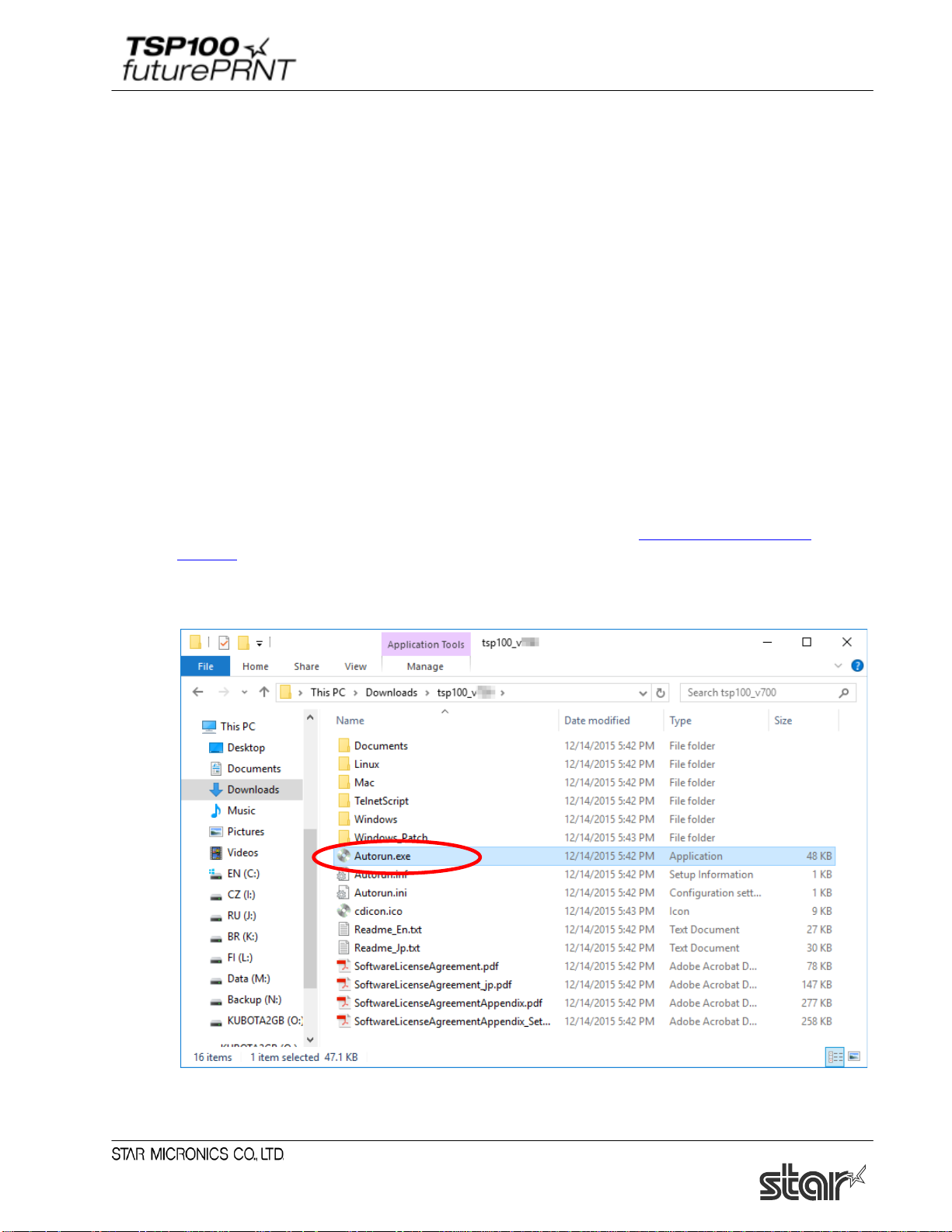
2) Extract the archive you downloaded and run "Autorun.exe".
www.star-m.jp/tsp100iii-
1
Page 7
Software Manual
<< Models supplied with CDs >>
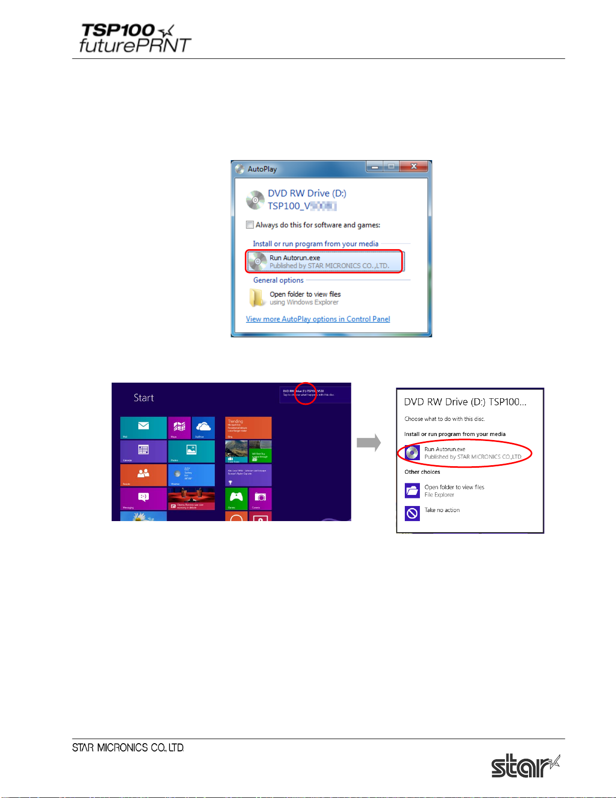
(1) Insert the CD-ROM supplied with the TSP100 futurePRNT into the CD-ROM drive of your
computer.
(2) When the following window appears, click “Run Autorun.exe”.
In Windows 8/8.1/10: Toast pop up will be appeared after CD-ROM is set.
After that, click [Run Autorun.exe].
2
Page 8
Software Manual
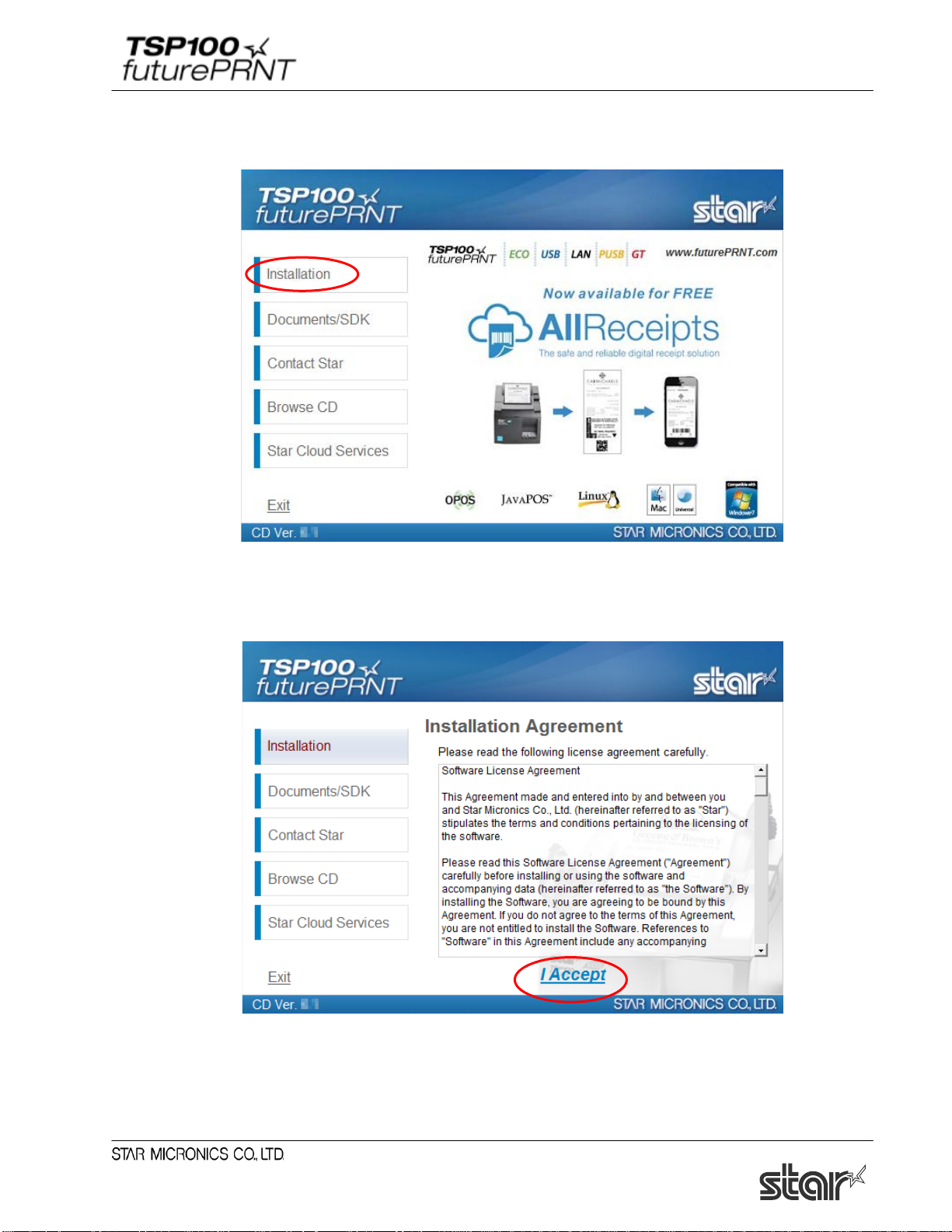
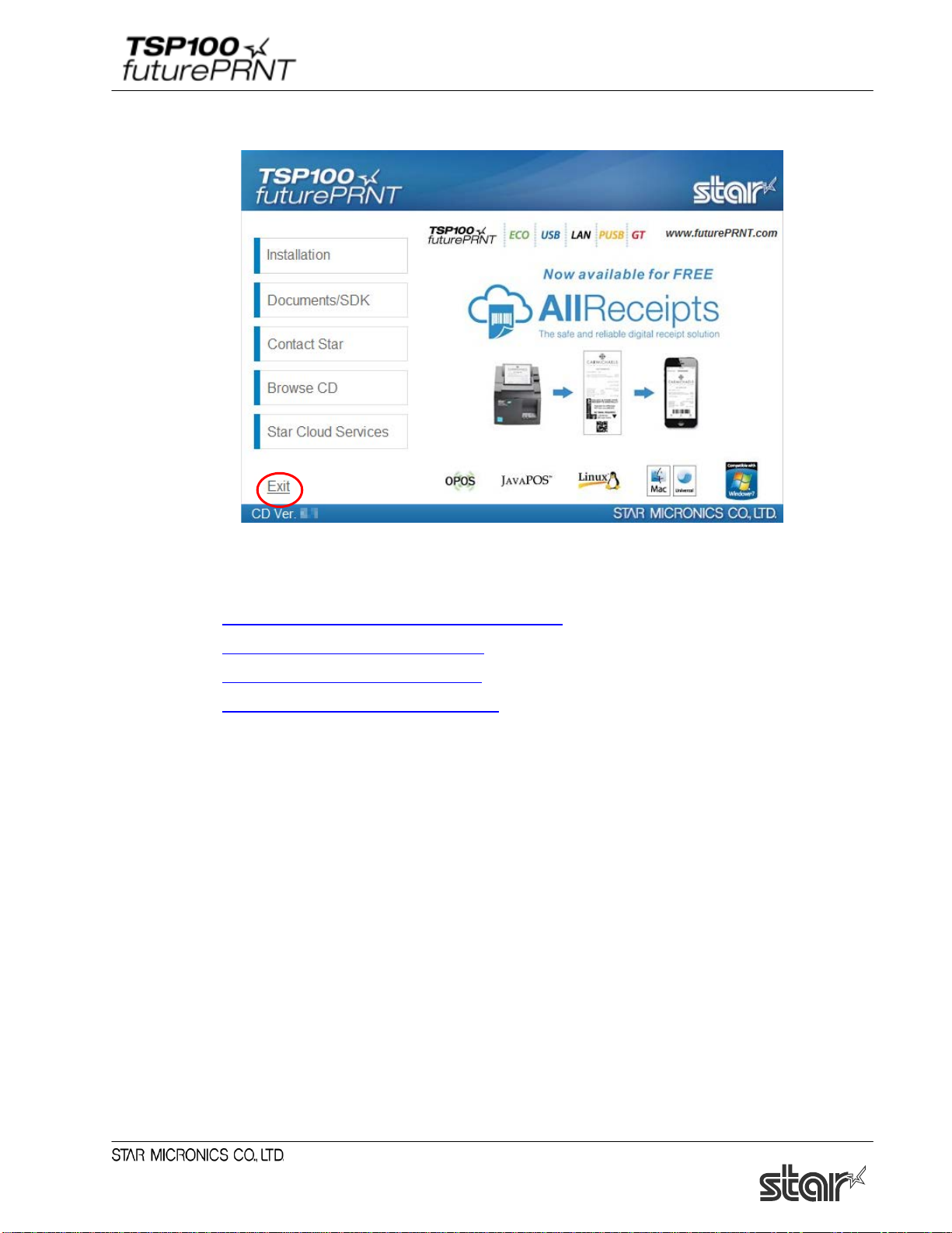
(3) Then, the following window will appear.
Click “Installation” on the menu.
(4) Read this software license agreement carefully. If you agree to the terms of this license, click
"I Accept".
(5) The "User Account Control" window will appear. Click "Yes".
3
Page 9
Software Manual
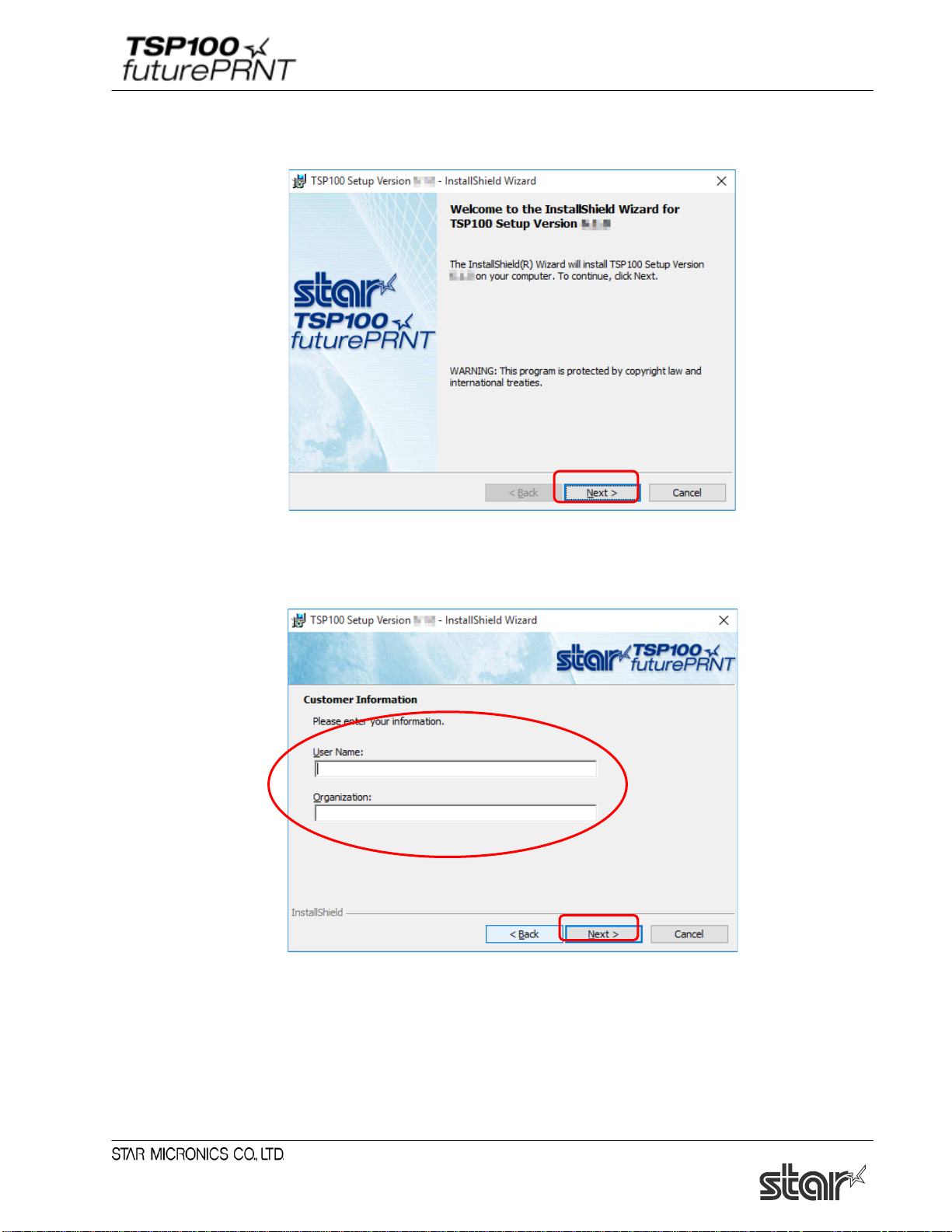
(6) Click “Next” to continue.
(7) Choose the user and then click “Next” to continue.
4
Page 10
Software Manual
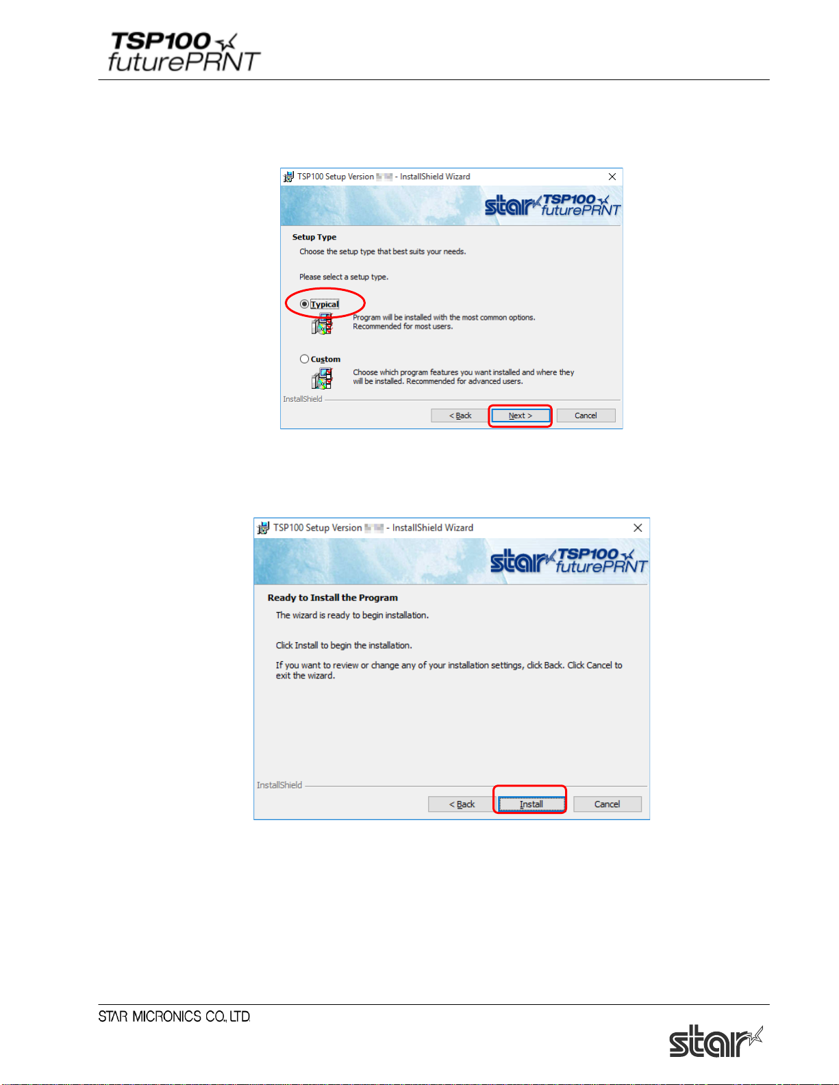
(8) Choose the “Typical” installation option to be sure that all of the TSP100 futurePRNT’s
options are installed and then click “Next” to continue.
(9) Click “Install” to begin the installation process.
5
Page 11
Software Manual
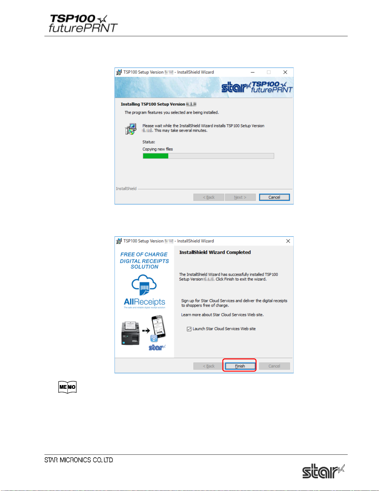
(10) The files and programs are now being installed on the computer.
(11) At this point, all drivers and programs have been installed. Click “Finish” to close the wizard.
If the "Launch Star Cloud Services Web site" check box is checked (default),
Star Cloud Services website will open after the installation wizard is finished.
6
Page 12
Software Manual
(12) Click "Exit" to close the following window.
(13) The subsequent steps vary depending on the model you are using.
1.2 Adding a Printer (TSP100U/PU/GT/ECO)
1.3 Adding a Printer (TSP100LAN)
1.4 Adding a Printer (TSP100IIIW)
1.5 Adding a Printer (TSP100IIILAN)
7
Page 13
Software Manual
1.2. Adding a Printer (TSP100U/PU/GT/ECO)
(1) Load roll paper in the TSP100 futurePRNT, and connect to a computer.
For information about how to load paper and connect to a computer, refer to the
TSP100 futurePRNT hardware manual.
To view the hardware manual, select "Documents/SDK" on the “CD auto” menu,
and click "Hardware Manual".
(2) Turn the TSP100 futurePRNT on.
With "Plug and Play", the computer detects a new hardware product and automatically
installs the printer driver.
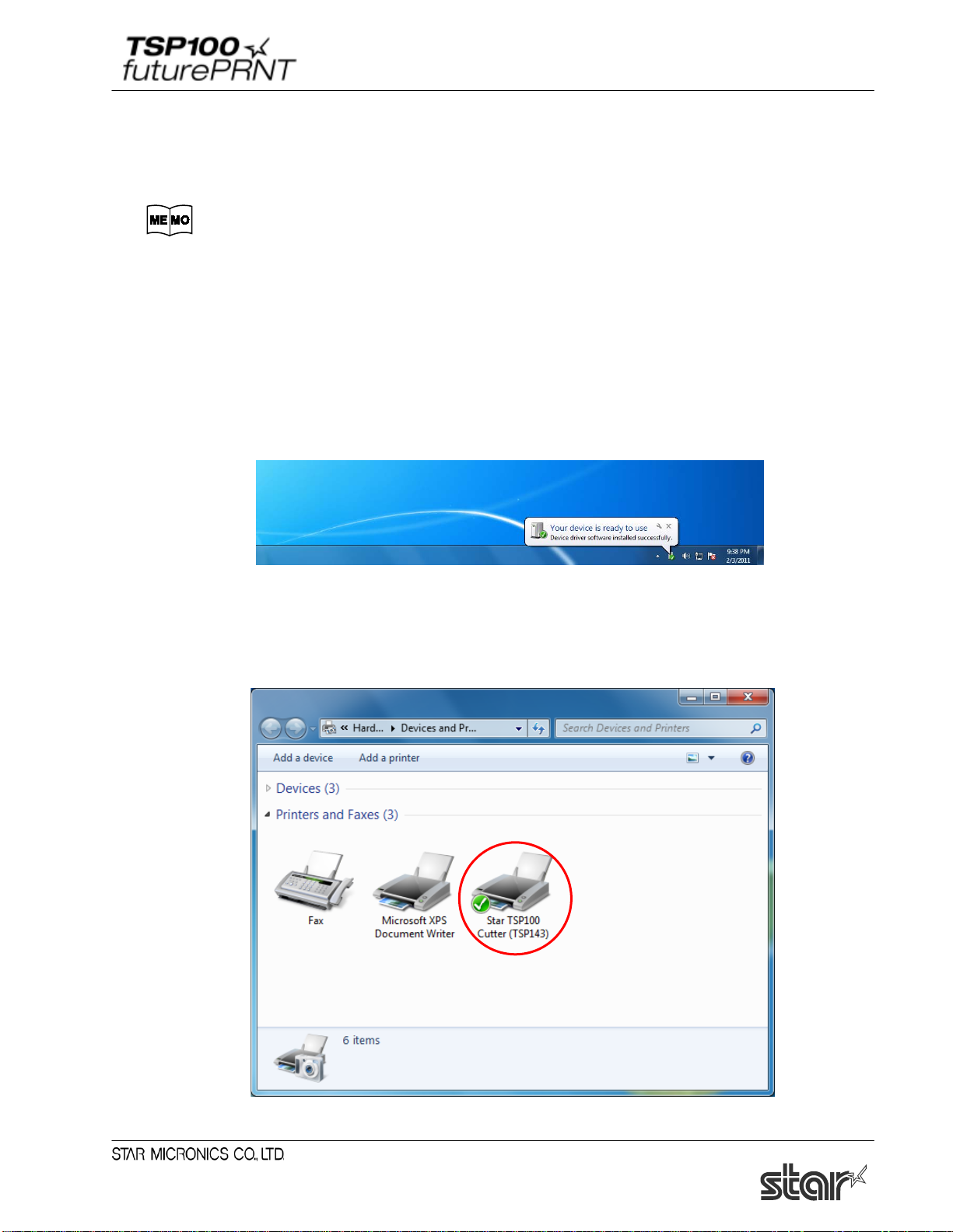
Then, the following window will appear in the lower right of the Windows screen.
(3) In Control Panel, select “Devices and Printers”.
If "Star TSP100" appears, installation is completed.
8
Page 14
Software Manual
1.3. Adding a Printer (TSP100LAN)
Prior to installation, use an Ethernet cable to connect the printer and an access point that can connect to
the same network the PC that will be used for configuration is on. For details, see the
Notes:Printer addition requires computer's administrator privileges.
1.3.1. Printer LAN Settings
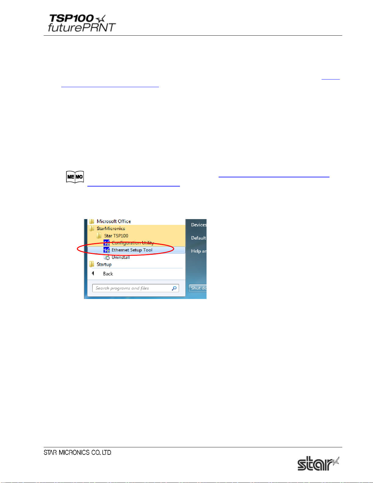
(1) Turn the TSP100 futurePRNT on.
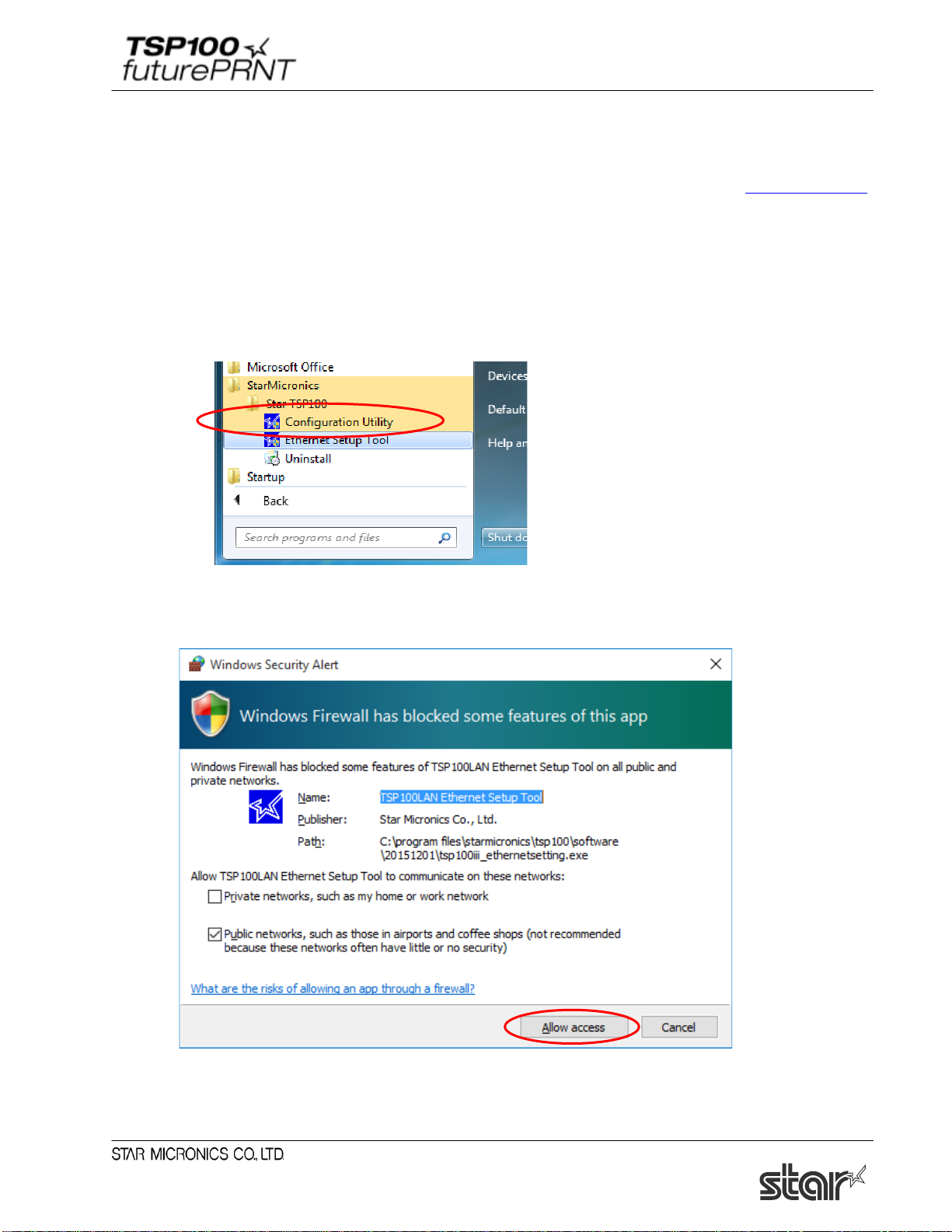
(2) From the Windows Start menu, select “Programs (All Programs)” - “StarMicronics” - “Star
TSP100” - “Ethernet Setup Tool”.
Hardware manual.
(3) "User Account Control" window will appear. Click "Yes".
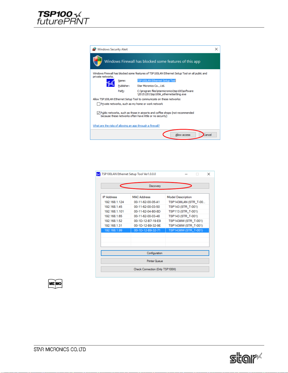
(4) If the "Windows Security Alert" screen is displayed, click [Allow access].
Notes: If you click [Cancel], you will not be able to search for the LAN printer.
9
Page 15
Software Manual
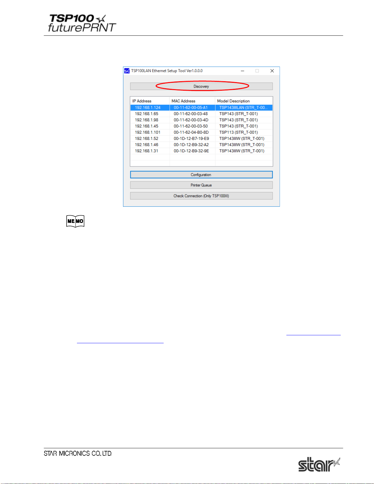
(5) The TSP100LAN Ethernet Setup Tool screen is displayed.
If the printer you want to install is not listed in the LAN printer list, click [Discovery].
The factory network settings of the TSP100LAN printer are as follows.
IP address: 0.0.0.0 (Unassigned)
Subnet mask: 0.0.0.0 (Unassigned)
Default gateway: 0.0.0.0 (Unassigned)
Use DHCP: ENABLE (Selected)
If at least one of the following conditions applies, you will not be able to configure an IP address for
any printers (with factory default settings) which have no IP address assigned.
- Using F/W V.2.0 or older
- Using CD Vol. 5.4 or older
Before starting operations, specify the IP address for the printer, referring to "Chapter 6 Guideline
for Using Ethernet Environment".
10
Page 16

Software Manual
(6) The TSP100LAN printer appears in the LAN printer list.
If multiple TSP100LAN printers are listed, you can identify the desired printer by referring to
the indicated MAC address.
If you wish to use the IP address assigned by the DHCP server, click the [Add printer queue]
button. Then proceed to Section
1.3.2, "Creating a Printer Queue", below.
If you wish to assign a fixed IP address for the printer, click [Change TCP/IP Setting].
Go to step 7
Go to section 1.3 .2.
You can find the printer's MAC address by printing a self-test.
Hold the FEED button down as you turn the printer ON to run self-printing.
11
Page 17
Software Manual
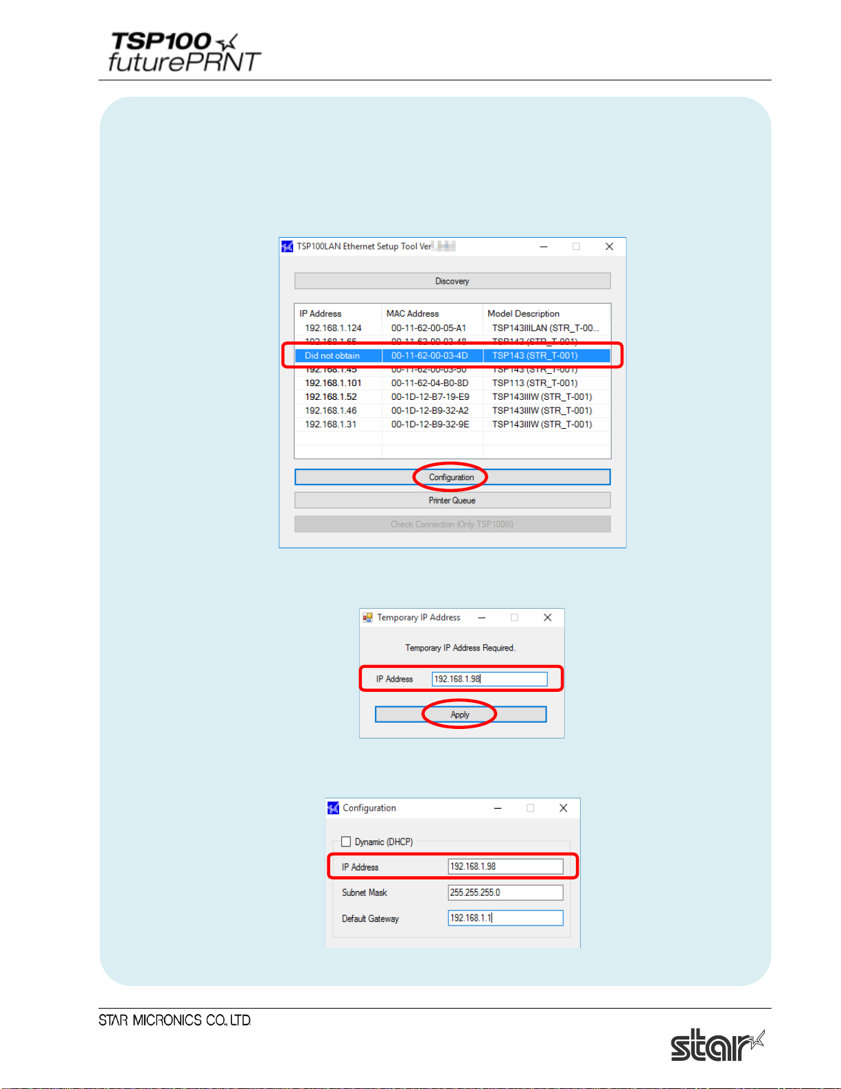
■ When the IP address cannot be obtained from the DHCP server :
When the DHCP server is not available, "Did not obtain" is displayed in the ‘IP address’ field for a
printer that is not assigned to any IP address. To use such a printer, follow the steps below to specify
the IP address.
1) Select a printer that is not assigned to any IP address, and then click [Configuration].
2) Enter a temporary IP address to assign, and then click [Apply].
3) The "Configuration" screen is displayed showing the entered temporary IP address in the IP
address field. Continue setting up a fixed IP address.
12
Page 18
Software Manual
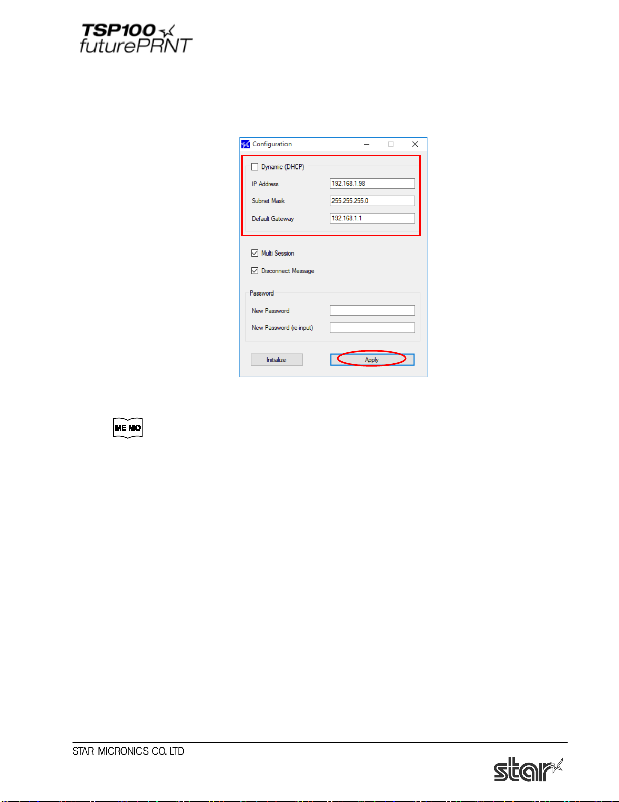
(7) Uncheck "Dynamic (DHCP)", enter the IP address, subnet mask, and default gateway, and then
click [Apply].
Ask your network administrator about the static IP addr ess and subnet mask to
use in the settings.
・If you enable “Multi Session”, it will be possible for terminals to get status from the printer
even when multiple terminals are connected simultaneously.
・If “Disconnect Message” is set to Enable, "NO HOST CONNECTION" will be printed when
the printer has been disconnected. This function is available in firmware version 110.110.100 or
later of the printer.
・ If you click Initialize, all settings (including the password setting) return to their factory
defaults.
・ It is possible to set a fixed IP address from another segment. If you do so, however, the printer
will no longer be locatable by the Ethernet Setup Tool's LAN search.
13
Page 19
Software Manual
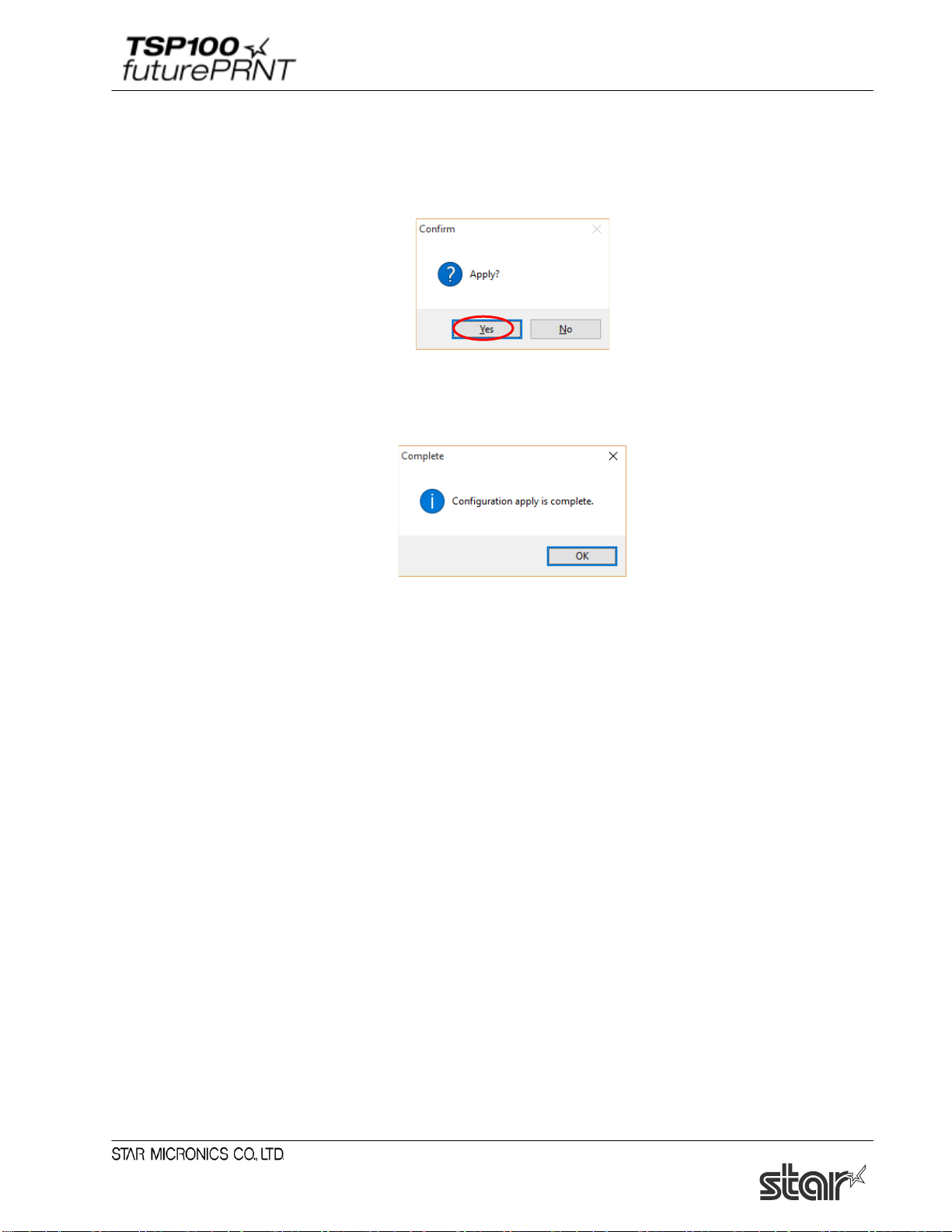
(8) Click [Yes] on the screen asking to confirm application. The configuration is saved to the
printer and printed out.
(9) A message is displayed indicating that the configuration was applied. Click [OK], and then
proceed to Section 1.3.2, "Creating a Printer Queue."
Note: After the printer reset, it may take a short time (perhaps 20 seconds) for the printer
to be found again.
If the printer fails to reappear on the printer list after a noticeable amount of time
has passed, retry the search by clicking again on the [Discovery] button.
14
Page 20

Software Manual
1.3.2. Creating a Printer Queue
(1) Select the printer to create a printer queue from the LAN printer list, and then click [Printer
Queue].
(2) The following dialog now appears. The dialog shows the queue name and port name for the
printer you are setting up. You can leave the names as they are, or you can change them to
anything you prefer. If you wish to use this printer as your default printer, check [Default
Printer]. If you want to output a test print after completing the settings, check [Print Test
Page]. After making appropriate settings, click [Apply].
The following characters can be used in queue and port names.
Queue name: Uppercase and lowercase letters, numerals (0 to 9) , hyphens,
underscores, periods, spaces, and parentheses.
Port name: Uppercase and lowercase letters, numerals (0 t o 9) , hyphens,
underscores, and perio ds.
15
Page 21
Software Manual
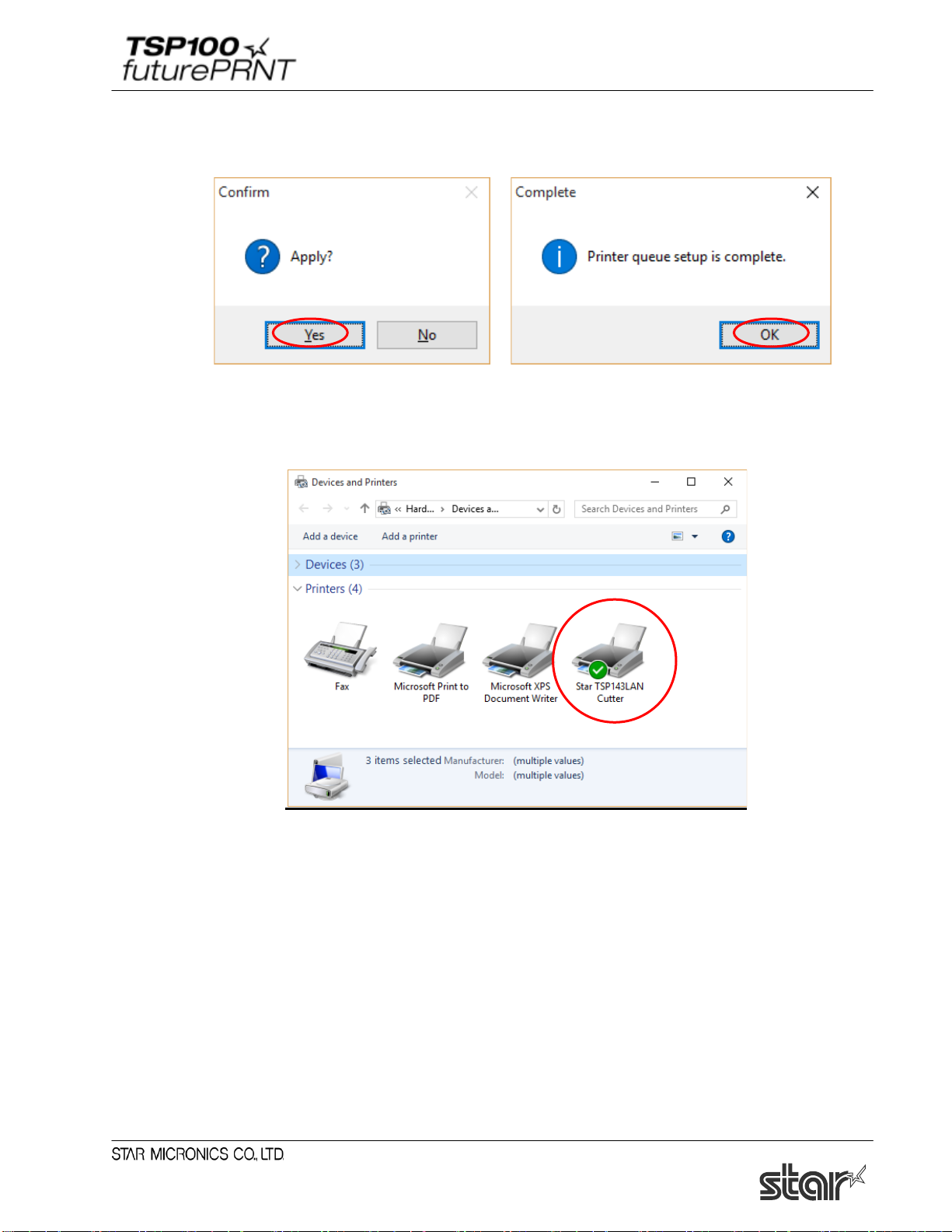
(3) Click [Yes] on the screen asking to confirm application. The printer queue is created. A
message is displayed indicating that setup is complete. Click [OK].
(4) In Control Panel, select “Devices and Printers”.
If the Star TSP100LAN printer is found in the window, installation is completed.
16
Page 22
Software Manual
1.4. Adding a Printer (TSP100IIIW)
This manual describes how to connect the printer using WPS.
If you are using Windows 7, you can also connect over an Ad-Hoc network. For details, see the
manual (Setup - Connect Tablet/PC).
Notes:Printer addition requires computer's administrator privileges.
1.4.1. Printer LAN Settings
(1) Turn the TSP100 futurePRNT on.
(2) Use WPS to connect the printer to the network.
Set your wireless access point to wait for a WPS connection, and then hold down the PAIR
button on the rear of the printer until the printer LED (blue) blinks.
When the WPS connection is made, the printer LED (blue) stops blinking and stays lit.
For details on WPS connections, see the TSP100IIIW Online manual (Setup -
Connecting with a Tablet/PC)
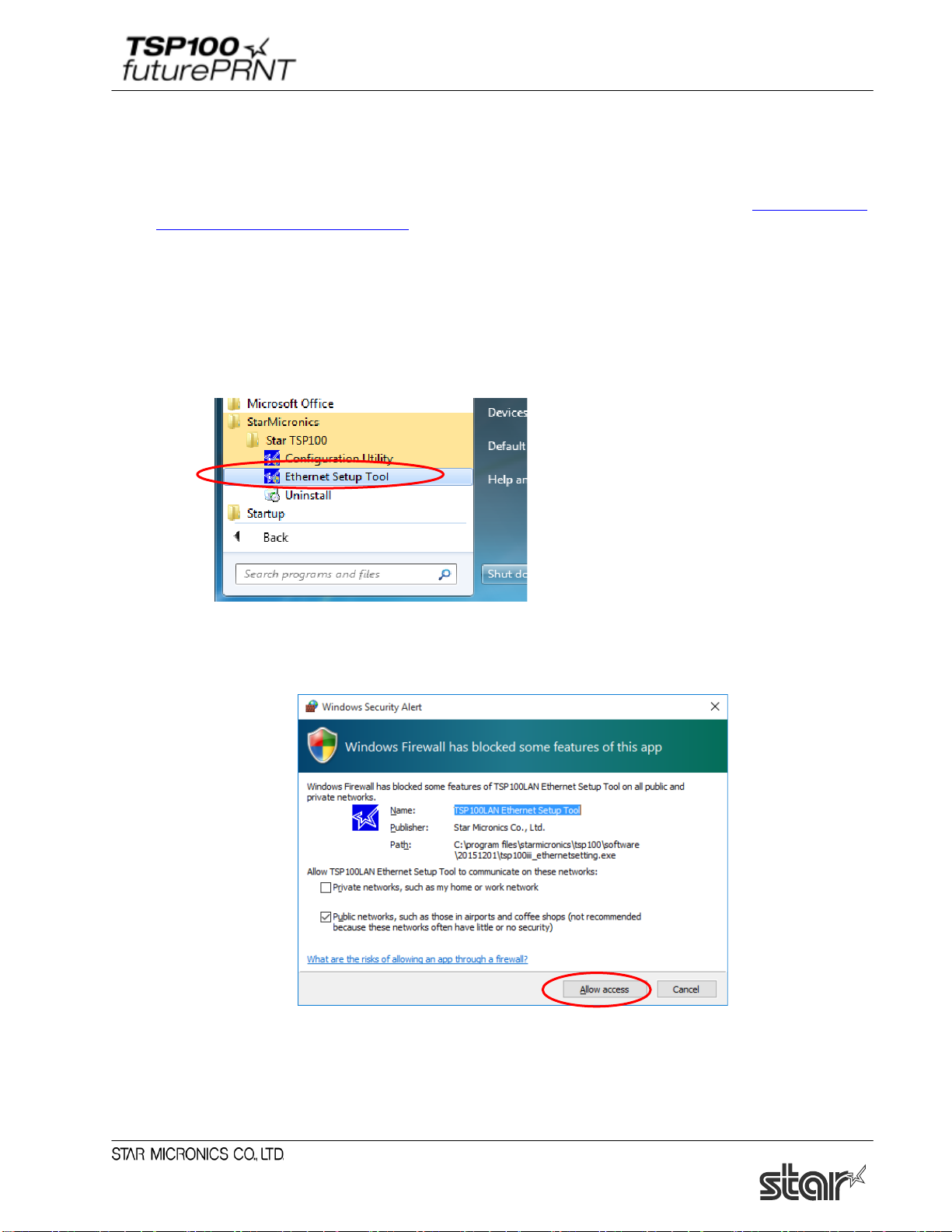
(3) From the Windows Start menu, select “Programs (All Programs)” - “StarMicronics” - “Star
TSP100” - “Ethernet Setup Tool”.
.
Online
(4) "User Account Control" window will appear. Click "Yes".
17
Page 23
Software Manual
(5) If the "Windows Security Alert" screen is displayed, click [Allow access].
Notes: If you click [Cancel], you will not be able to search for the LAN printer.
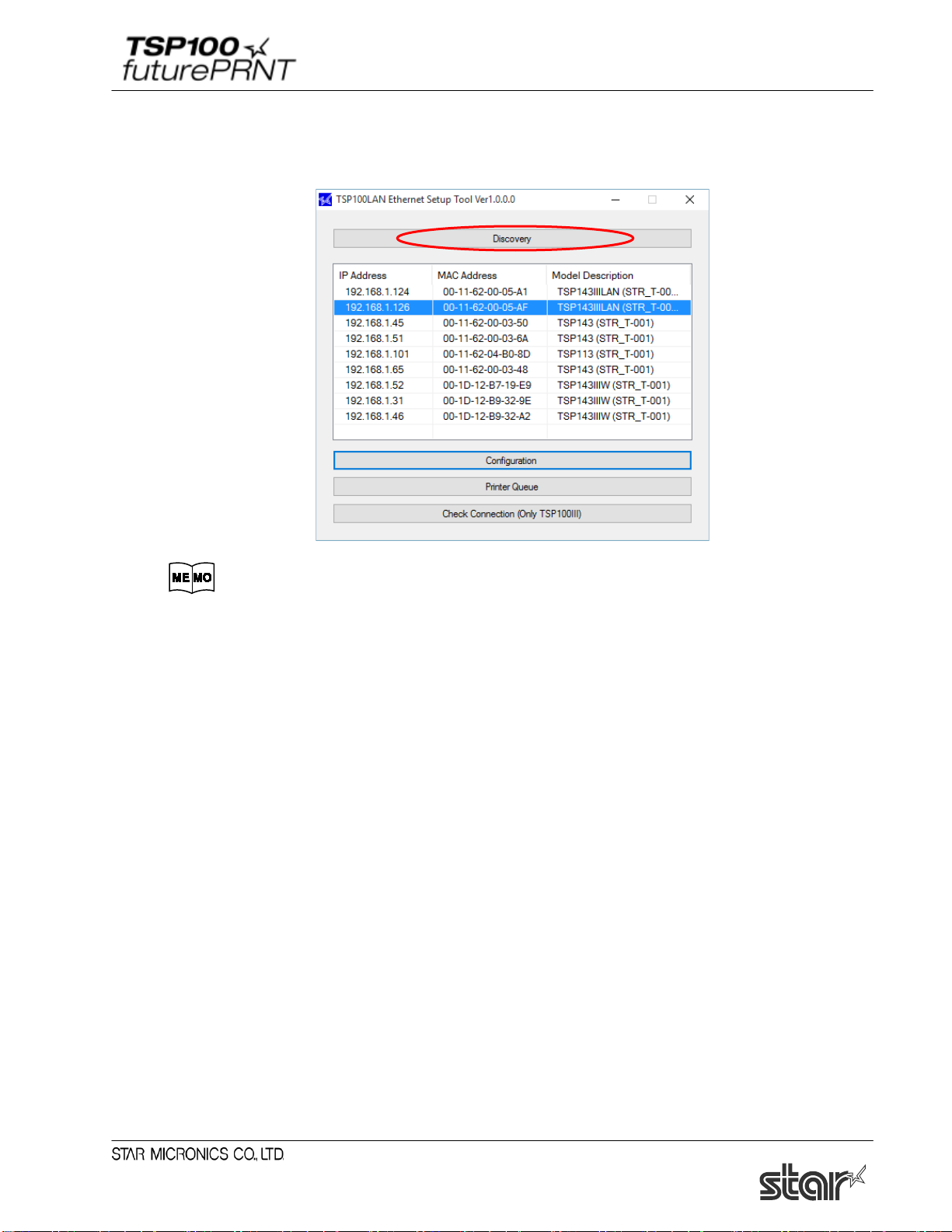
(6) The TSP100LAN Ethernet Setup Tool screen is displayed.
If the printer you want to install is not listed in the LAN printer list, click [Discovery].
The factory network settings of the TSP100IIIW printer are as follows.
Network Mode: Ad-Hoc *
IP address: 0.0.0.0 (Unassigned)
Subnet mask: 0.0.0.0 (Unassigned)
Default gateway: 0.0.0.0 (Unassigned)
Use DHCP: ENABLE (Selected)
* The printer automatically enters the infrastructure mode when it connects over WPS.
18
Page 24
Software Manual
(7) The TSP100 Ethernet printer appears in the LAN printer list.
If multiple TSP100IIIW printers are listed, click [Check connection] to check whether you can
communicate with the printer. The connected printer's LED (blue) will blink.
If you wish to use the IP address assigned by the DHCP server, then proceed to Section
1.4.2,
"Creating a Printer Queue", below.
If you wish to assign a fixed IP address for the printer, click [Configuration].
Go to step 8
Go to section 1.4 .2.
19
Page 25
Software Manual
■ When the IP address cannot be obtained from the DHCP server :
When the DHCP server is not available, "Did not obtain" is displayed in the ‘IP address’ field for a
printer that is not assigned to any IP address. To use such a printer, follow the steps below to specify
the IP address.
1) Select a printer that is not assigned to any IP address, and then click [Configuration].
2) Enter a temporary IP address to assign, and then click [Apply].
3) Connect to the printer using the temporarily assigned IP address. The Web Configuration screen
is displayed. see step (8) and the subsequent steps to complete the setting of a fixed IP address.
20
Page 26
Software Manual
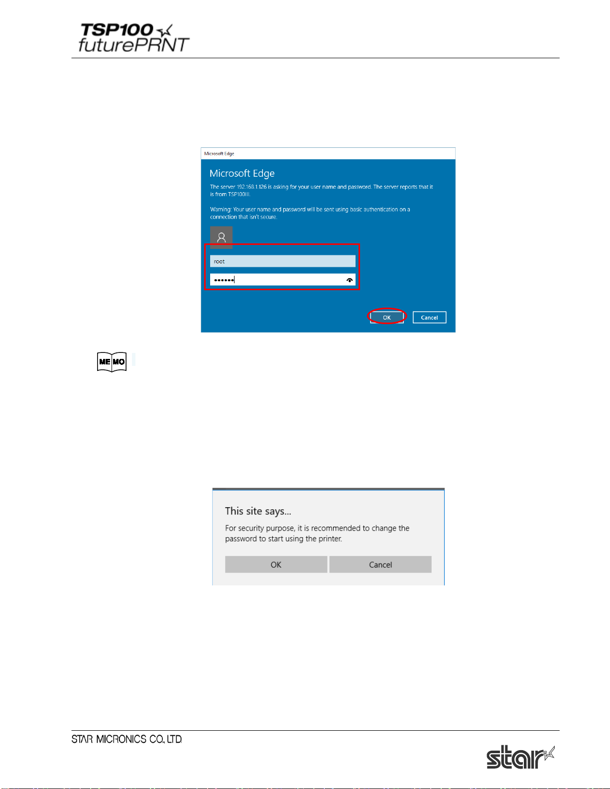
(8) Open [Login] from the menu displayed on the left side of the setting screen, or the menu button
displayed on the upper left, and login with:
Login name: root / password: [Changed password or the default password (public)].
The default login name and password are as follows:
Login name: ro ot
Password: publi c
(9) The following message is displayed when you are using the default password. Select [OK] to
change the password or [Cancel] to not change the password.
If [OK] is selected, a screen to change the password will open. After changing the password,
return to the following step.
21
Page 27
Software Manual
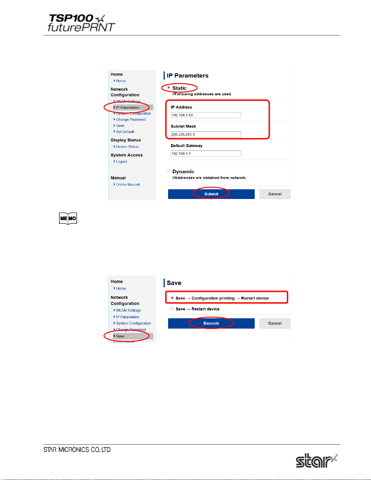
(10) From the menu displayed on the left side of the setting screen or the menu button displayed on
the upper left, open [IP Parameters] , select “Static” and enter the IP Address, Subnet Mask,
and tap [Submit].
Ask your network administrator about the static IP addr ess and subnet mask to use
in the settings.
(11) From the menu of the menu button on the upper left, open [Save], select
"Save"→"Configuration Printing"→"Restart device", and tap [Execute].
The settings are saved to the printer and printed out.
(12) The settings are saved to the printer and printed out. Then proceed to Section 1.4.2, "Creating a
Printer Queue."
Note: After the printer reset, it may take a short time (perhaps 20 seconds) for the printer
to be found again.
If the printer fails to reappear on the printer list after a noticeable amount of time
has passed, retry the search by clicking again on the [Discovery] button.
22
Page 28

Software Manual
1.4.2. Creating a Printer Queue
(1) Select the printer to create a printer queue from the LAN printer list, and then click [Printer
Queue].
(2) The following dialog now appears. The dialog shows the queue name and port name for the
printer you are setting up. You can leave the names as they are, or you can change them to
anything you prefer. If you wish to use this printer as your default printer, check [Default
Printer]. If you want to output a test print after completing the settings, check [Print Test
Page]. After making appropriate settings, click [Apply].
The following characters can be used in queue and port names.
Queue name: Uppercase and lowercase letters, numerals (0 to 9) , hyphens,
underscores, periods, spaces, and parentheses.
Port name: Uppercase and lowercase letters, numerals (0 t o 9) , hyphens,
underscores, and perio ds.
23
Page 29
Software Manual
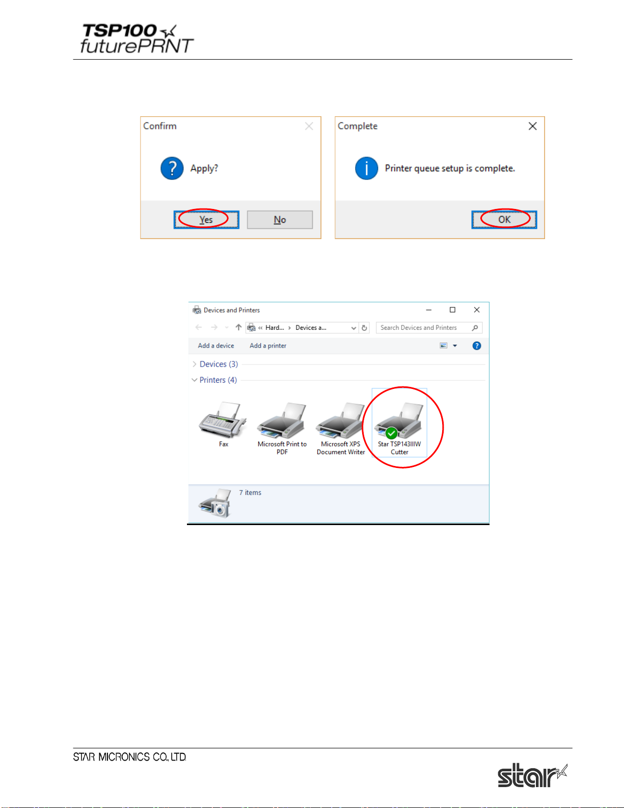
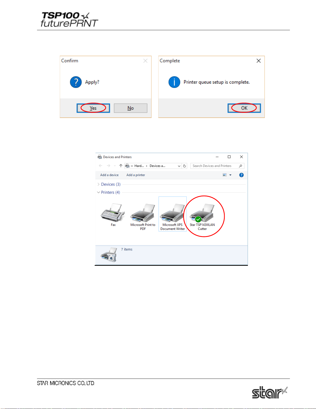
(3) Click [Yes] on the screen asking to confirm application. The printer queue is created. A
message is displayed indicating that setup is complete. Click [OK].
(4) In Control Panel, select “Devices and Printers”.
If the Star TSP100IIIW printer is found in the window, installation is completed.
24
Page 30
Software Manual
1.5. Adding a Printer (TSP100IIILAN)
Prior to installation, use an Ethernet cable to connect the printer and an access point that can connect to
the same network the PC that will be used for configuration is on. For details, see the
manual (Setup – Connect Tablet/PC).
Notes:Printer addition requires computer's administrator privileges.
1.5.1. Printer LAN Settings
(1) Turn the TSP100 futurePRNT on.
(2) From the Windows Start menu, select “Programs (All Programs)” - “StarMicronics” - “Star
TSP100” - “Ethernet Setup Tool”.
Online hardware
(3) "User Account Control" window will appear. Click "Yes".
(4) If the "Windows Security Alert" screen is displayed, click [Allow access].
Notes: If you click [Cancel], you will not be able to search for the LAN printer.
25
Page 31
Software Manual
(5) The TSP100LAN Ethernet Setup Tool screen is displayed.
If the printer you want to install is not listed in the LAN printer list, click [Discovery].
The factory network settings of the TSP100IIILAN pr i nt er are as follows.
IP address: 0.0.0.0 (Unassigned)
Subnet mask: 0.0.0.0 (Unassigned)
Default gateway: 0.0.0.0 (Unassigned)
Use DHCP: ENABLE (Selected)
26
Page 32

Software Manual
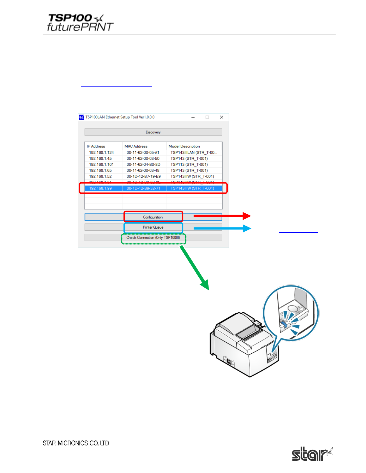
(6) The TSP100 Ethernet printer appears in the LAN printer list.
If multiple TSP100IIILAN printers are listed, click [Check connection] to check whether you
can communicate with the printer. The connected printer's LED (blue) will blink.
If you wish to use the IP address assigned by the DHCP server, then proceed to
Section 1.5.2,
"Creating a Printer Queue", below.
If you wish to assign a fixed IP address for the printer, click [Configuration].
Go to step 7
Go to section 1.5 .2.
27
Page 33

Software Manual
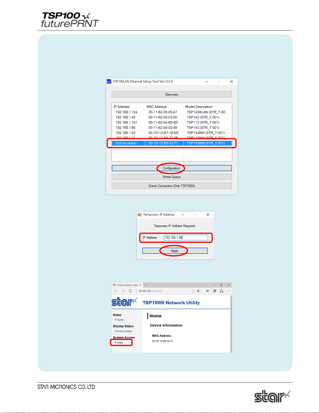
■ When the IP address cannot be obtained from the DHCP server :
When the DHCP server is not available, "Did not obtain" is displayed in the ‘IP address’ field for a
printer that is not assigned to any IP address. To use such a printer, follow the steps below to specify
the IP address.
1) Select a printer that is not assigned to any IP address, and then click [Configuration].
2) Enter a temporary IP address to assign, and then click [Apply].
3) Connect to the printer using the temporarily assigned IP address. The Web Configuration screen
is displayed. see step (7) and the subsequent steps to complete the setting of a fixed IP address.
28
Page 34
Software Manual
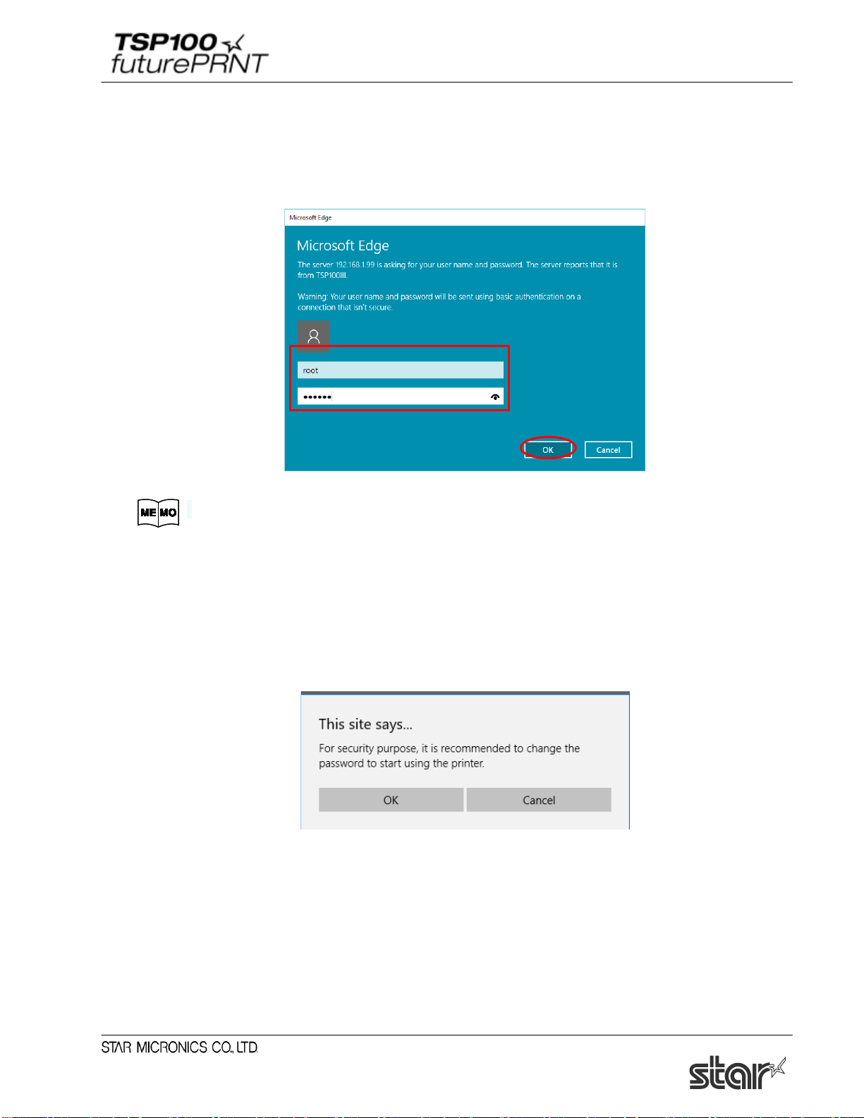
(7) Open [Login] from the menu displayed on the left side of the setting screen, or the menu button
displayed on the upper left, and login with:
Login name: root / password: [Changed password or the default password (public)].
The default login name and password are as follows:
Login name: ro ot
Password: publi c
(8) The following message is displayed when you are using the default password. Select [OK] to
change the password or [Cancel] to not change the password.
If [OK] is selected, a screen to change the password will open. After changing the password,
return to the following step.
29
Page 35

Software Manual
(9) From the menu displayed on the left side of the setting screen or the menu button displayed on
the upper left, open [IP Parameters] , select “Static” and enter the IP Address, Subnet Mask,
and tap [Submit].
Ask your network administrator about the static IP addr ess and subnet mask to use
in the settings.
(10) From the menu of the menu button on the upper left, open [Save], select
"Save"→"Configuration Printing"→"Restart device", and tap [Execute].
The settings are saved to the printer and printed out.
(11) The settings are saved to the printer and printed out. Then proceed to Section 1.5.2, "Creating a
Printer Queue."
Note: After the printer reset, it may take a short time (perhaps 20 seconds) for the printer
to be found again.
If the printer fails to reappear on the printer list after a noticeable amount of time
has passed, retry the search by clicking again on the [Discovery] button.
30
Page 36

Software Manual
1.5.2. Creating a Printer Queue
(1) Select the printer to create a printer queue from the LAN printer list, and then click [Printer
Queue].
(2) The following dialog now appears. The dialog shows the queue name and port name for the
printer you are setting up. You can leave the names as they are, or you can change them to
anything you prefer. If you wish to use this printer as your default printer, check [Default
Printer]. If you want to output a test print after completing the settings, check [Print Test
Page]. After making appropriate settings, click [Apply].
The following characters can be used in queue and port names.
Queue name: Uppercase and lowercase letters, numerals (0 to 9) , hyphens,
underscores, periods, spaces, and parentheses.
Port name: Uppercase and lowercase letters, numerals (0 t o 9) , hyphens,
underscores, and perio ds.
31
Page 37
Software Manual
(3) Click [Yes] on the screen asking to confirm application. The printer queue is created. A
message is displayed indicating that setup is complete. Click [OK].
(4) In Control Panel, select “Devices and Printers”.
If the Star TSP100IIILAN printer is found in the window, installation is completed.
32
Page 38
Software Manual
1.6. Uninstallation
(1) Turn the printer off.
(2) From the Windows Start menu, select “All Programs or All Apps” → “StarMicronics” →
“Star TSP100” → “Uninstall”.
(3) In the User Account Control dialog box, click the “Yes”.
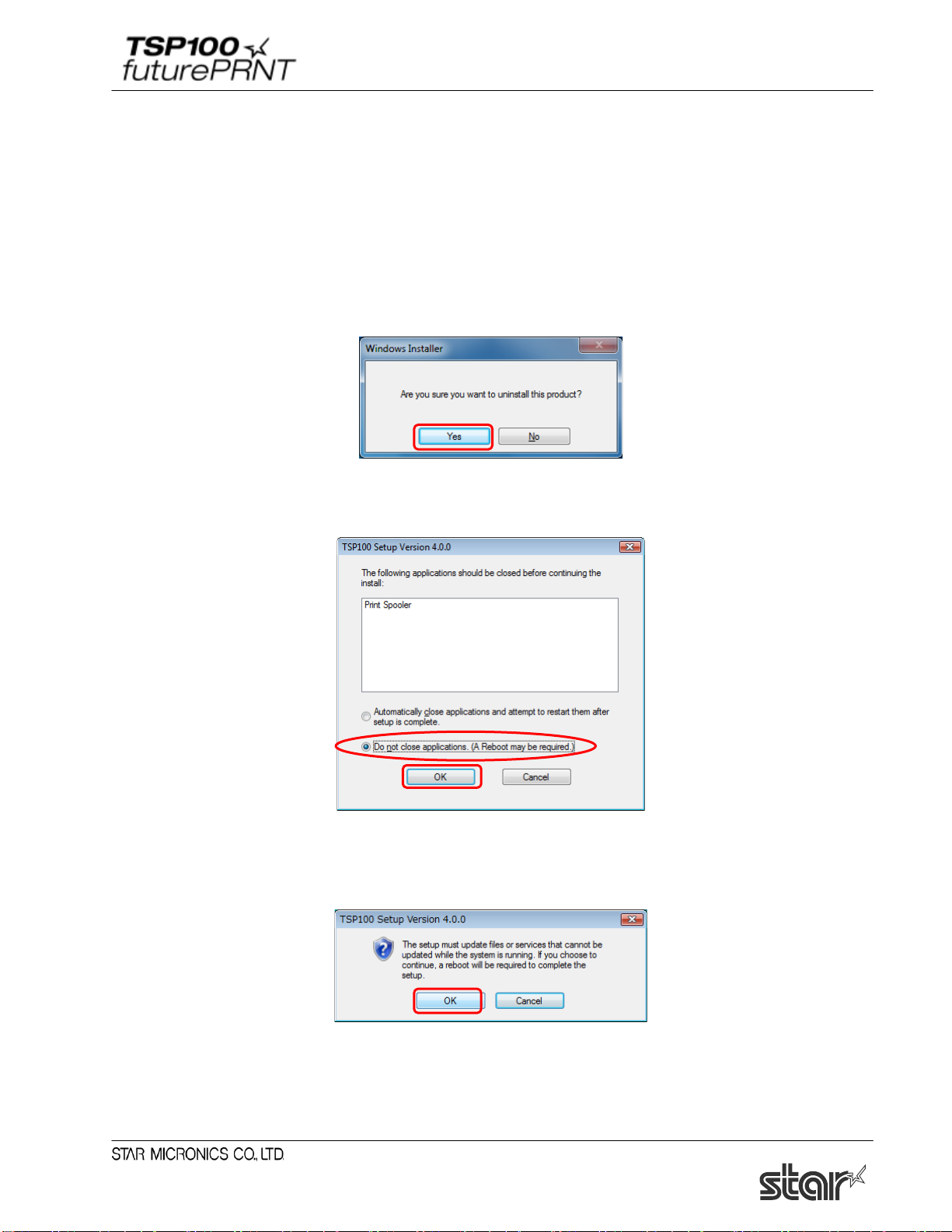
(4) When the following confirmation dialog box appears, click “Yes” to continue.
(5) If the following window appears, select “Do not close applications” and click “OK”.
(6) If the following window appears, click “OK”.
33
Page 39

Software Manual
(7) The uninstaller launches to remove all of the TSP100 futurePRNT software form your
computer.
34
Page 40
Software Manual
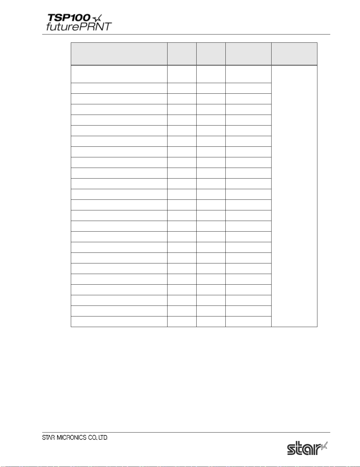
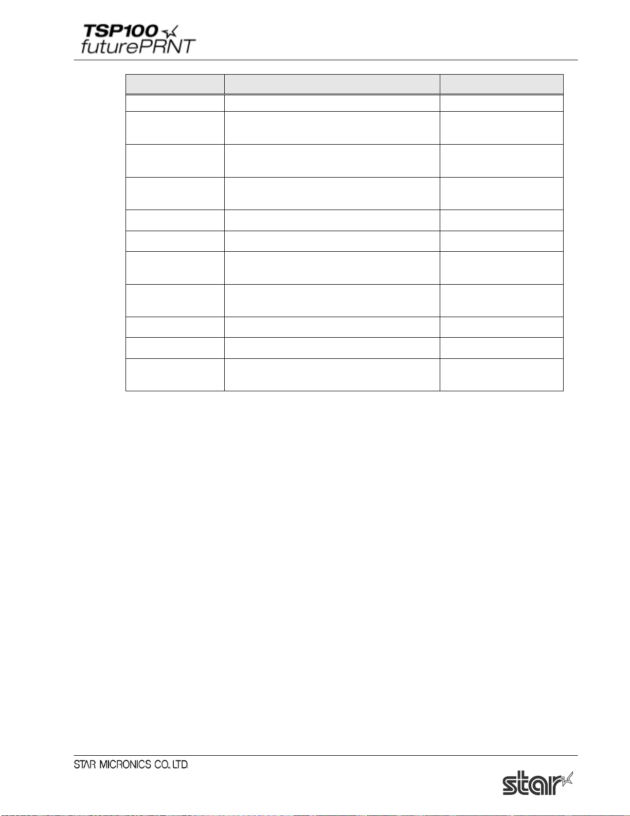
Peripheral Unit Type
Buzzer
Peripheral Unit 1
Document Bottom
Peripheral Unit 2
No Use
Buzzer 1: On Time
500 milliseconds
Buzzer 1: Off Time
2000 milliseconds
Buzzer 1: Repeat
5
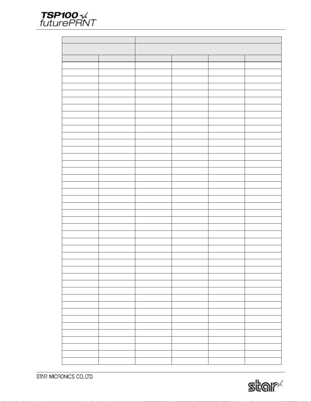
Document printing finishes
0.5 seconds on
Stops
FEED button plessed
0.5 seconds on
2 seconds off
0.5 seconds on
2 seconds off
0.5 seconds on
0.5 seconds on
0.5 seconds on
0.5 seconds on
2 seconds off
Document printing finishes
2 seconds off
2 seconds off
2 seconds off
2 seconds off
2. Features
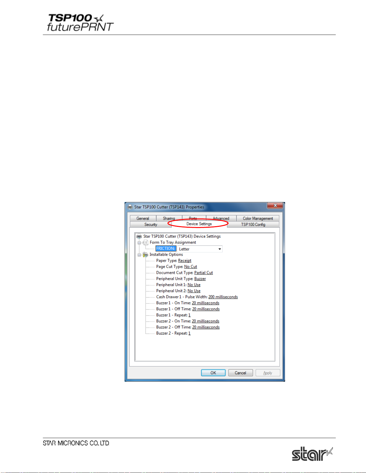
2.1. Star Windows Printer Driver
The Star Windows Printer Driver is used to apply the futurePRNT series in Windows 10, 8.1, 8 or
Windows 7. Using this printer driver allows you to handle basic printing functions in many
Windows applications. It also allows you to configure graphic logo and peripheral unit (buzzers
and cash drawers) settings.
This printer driver, which supports a diverse range of device fonts, enables you to generate and
print barcodes and 2D codes of various standards or sizes using barcode fonts and 2D code fonts,
and also control the printer using control fonts.
The following shows a driver setting example when a buzzer is used as an option.
Example of driver settings:
2.2. OPOS Driver
OPOS(OLE for Retail POS) was created by industry leaders as a device standard for POS
hardware. OPOS is a Win32-based architecture for POS device access. The benefits of this
standard are realized in the ease of access to hardware in not only outputting data to devices, but
also reading back the status of the device.
This OPOS driver can be used with any existing OPOS compliant application. Star also
recommends use of the OPOS standard to any developer creating a Win32-based retail software
application.
Star’s OPOS driver offers full compliance with the OPOS standard version 1.13.
35
Page 41

Software Manual
2.3. JavaPOS Driver
JavaPOS (Java for Point of Sale Devices) is an architecture used to access Java-based POS
peripheral units. It has a feature that enables operations in a platform-independent environment,
taking advantage of the OPOS standard. Also, in a Java virtual computer, the minimum system
requirements are lowered, thus reducing overall system costs as well.
This driver offers full compliance with the JavaPOS standard version 1.13.
The location of the JavaPOS driver installer is different for Windows 32-bit and 64-bit systems.
Confirm your operating environment and then install the necessary package.
Installer Location for Windows 32-bit Environments:
Program Files\StarMicronics\TSP100\Software\20151201\JavaPOSExamples
Installer Location for Windows 64-bit Environments:
64-bit Java Operation Environment:
Program Files\StarMicronics\TSP100\Software\20151201\JavaPOSExamples
32-bit Java Operation Environment:
Program Files(x86)\StarMicronics\TSP100\Software\20151201\JavaPOSExamples
To use this driver under the JavaPOS application, you should set the Java runtime environment to
Java Runtime Environment (JRE)1.5 or later.
To use this driver in Java Runtime Environment version 1.4.2, configure the following settings as
a starting option to run the JavaPOS application.
-Dsmj.dllpath=<StarIOPort.dll and StarIOJ.dll absolute-path-of-storage-folder>
At normal installation, the DLL file above is stored in the following folder.
Program Files\StarMicronics\TSP100\Software\20151201
Setting example:
Java–Dsmj.dllpath=
”C:\Program Files\StarMicronics\TSP100\Software\20151201” application.class
2.4. Star Virtual Serial Port Emulator
This function allows you to use the TSP100U/PU/GT/ECO with the USB interface equipped or
the TSP100LAN, TSP100IIIW and TSP100IIILAN with the Ethernet interface equipped using
applications for a serial printer.
Notes: This function may not be available depending on applications.
36
Page 42

Software Manual
2.5. ESC/POS Mode
The TSP100 futurePRNT provides ESC/POS mode emulation, which can be configured in
“TSP100 Configuration Utility”. Thus, even if your current software is designed for the ESC/POS
mode, you will be able to use it as is, without making changes.
The functions (logo printing, journal, etc.) of the TSP100 futurePRNT remain usable even when
you print in the ESC/POS mode.
For information about how to use the ESC/POS mode, refer to "
Printer)".
4.18 Print Job Routing (Write
2.6. Star Virtual TCP/IP Port Emulator
<TSP100LAN, TSP100IIIW and TSP100III LAN only>
You can use the TSP100LAN Setup Utilities to set up virtual TCP/IP ports. This will enable you
to continue using applications that directly designate their own TCP/IP sockets.
37
Page 43
Software Manual
3. Windows Printer Driver Usage
3.1. Device Settings
Various functions of this driver can be configured in “Properties” menu of the printer.
In case of using Windows 8.1 and 8, change the setting from “Desktop UI” in order to change
settings.
First, follow the steps shown below to open the Properties window.
Notes:
Device settings require computer administrator privileges.
(1) In Control Panel, select “Devices and Printers”.
(2) Right-click on the icon of the target printer queue. Then, in the pull-down menu, select
“Printer Properties”.
(3) Click “Device Settings”.
38
Page 44

Software Manual
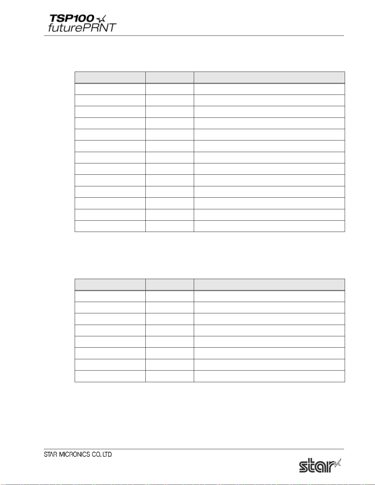
Paper Type
You can choose the length of each printed page.
Value Default Details
Receipt * Pages have variable length (printed to last line).
Ticket All printed pages have same length.
Page Cut Type (Cutter Model only)
You can choose the cut type that is performed at the end of all intermediate pages (all pages up to
the last page).
Value Default Details
No Cut * No intermediate pages are fed to the cutter.
Partial Cut All intermediate pages are fed to the cutter and are partially cut.
Document Cut Type
You can choose the Cut action for the final page.
< Cutter Model >
Value Default Details
No Cut The final page is not fed to the cutter.
Partial Cut * The final page is fed to the cutter and partially cut.
< Tear Bar Model >
Value Default Details
No Cut The final page is not fed to the tear bar.
Tear Bar * The final page is fed to the tear bar.
39
Page 45

Software Manual
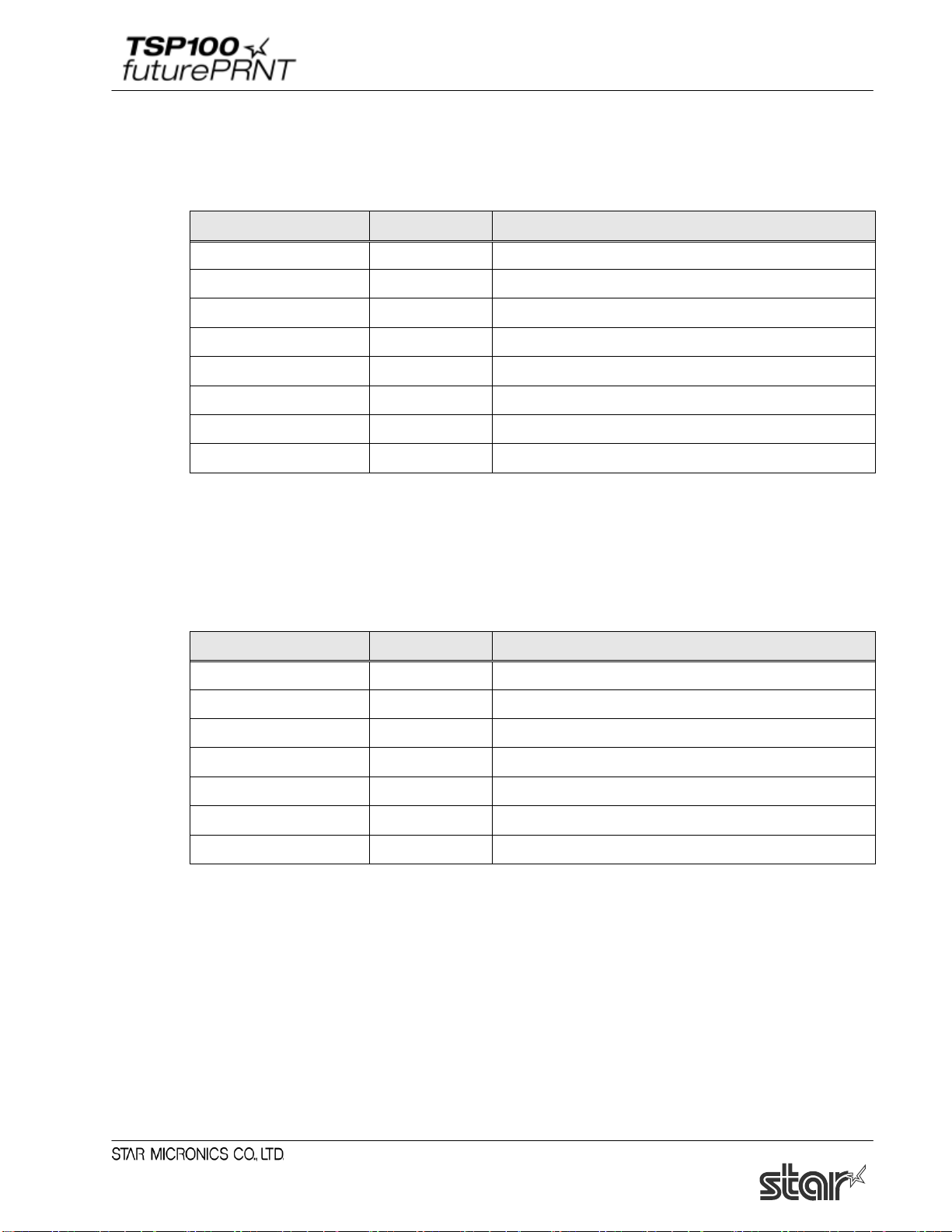
Value
Default
Details
Buzzer
*
Use buzzers as peripheral device.
Cash Drawer
Use buzzers as peripheral device.
Value
Default
Details
No Use
*
Peripheral unit 1 not used.
Document Top
Activate at top of document.
Page Top
Activate at top of page.
Page Bottom
Activate at bottom of page.
Document Bottom
Activate at bottom of document.
Value
Default
Details
No Use
*
Peripheral unit 2 not used.
Document Top
Activate at top of document.
Page Top
Activate at top of page.
Page Bottom
Activate at bottom of page.
Peripheral Unit Type
Use this setting to select the type of peripheral to be used with the printer.
Caution:
When using a peripheral unit such as a cash drawer other than a buzzer, do not select
"Buzzer".
If selected, it may result in damage to a peripheral unit.
Notes:
The buzzer and cash drawer are optional devices.
They cannot be used at the same time.
Peripheral Unit 1
This setting selects the action timing for peripheral unit 1.
Note that the Page Top and Page Bottom selections are not available if you have set the Peripheral
Unit Type to Cash Drawer.
Peripheral Unit 2
This setting selects the action timing for peripheral unit 2.
Note that the Page Top and Page Bottom selections are not available if you have set the Peripheral
Unit Type to Cash Drawer.
Document Bottom Activate at bottom of document.
40
Page 46
Software Manual
20 milliseconds
*
Sound on for 0.02 sec.
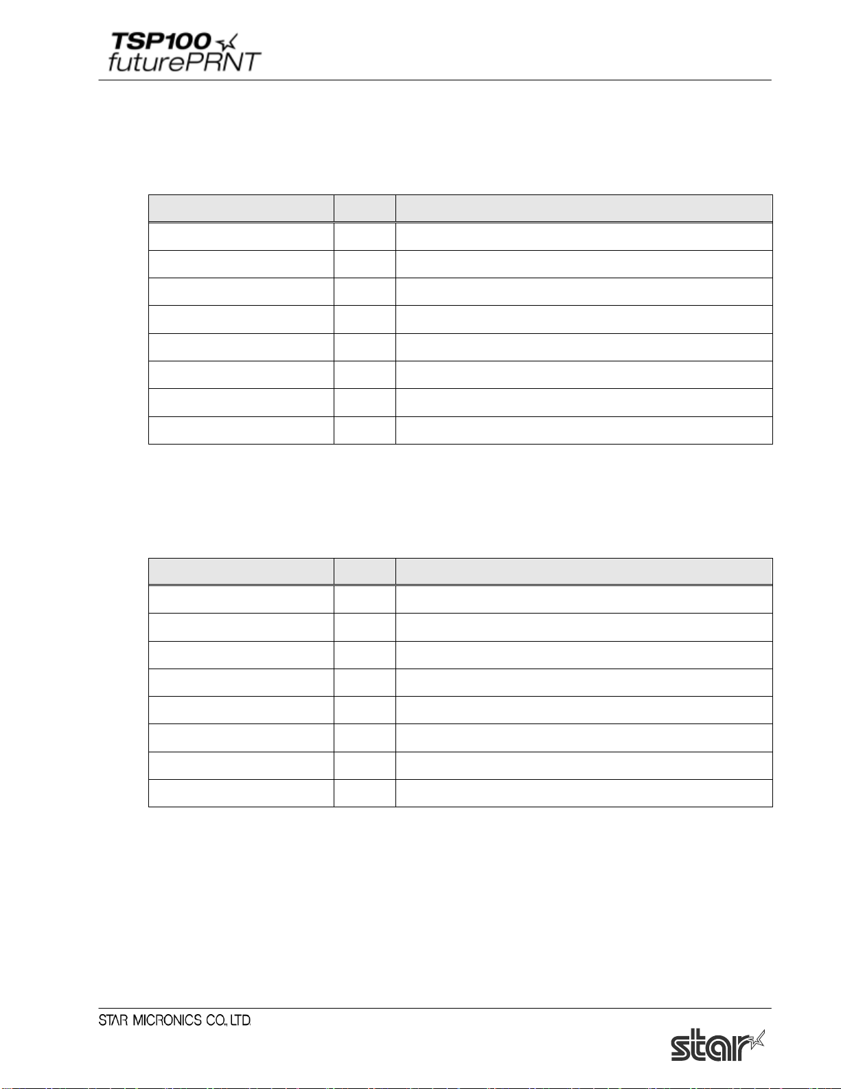
Cash Drawer 1 Pulse Width
You can choose the length of the open drawer signal that is sent from the printer to Cash Drawer 1.
Value Default Details
10 milliseconds Pulse width is set as 0.01 sec.
100 milliseconds Pulse width is set as 0.1 sec.
200 milliseconds * Pulse width is set as 0.2 sec.
300 milliseconds Pulse width is set as 0.3 sec.
400 milliseconds Pulse width is set as 0.4 sec.
500 milliseconds Pulse width is set as 0.5 sec.
600 milliseconds Pulse width is set as 0.6 sec.
700 milliseconds Pulse width is set as 0.7 sec.
800 milliseconds Pulse width is set as 0.8 sec.
900 milliseconds Pulse width is set as 0.9 sec.
1,000 milliseconds Pulse width is set as 1.0 sec.
1,100 milliseconds Pulse width is set as 1.1 sec.
1,200 milliseconds Pulse width is set as 1.2 sec.
Buzzer1 - On Time
If the Peripheral Unit Type is set to Buzzer, this setting selects the beep ON time for the buzzer
operating as peripheral unit 1.
Value Default Details
40 milliseconds Sound on for 0.04 sec.
100 milliseconds Sound on for 0.1 sec.
200 milliseconds Sound on for 0.2 sec.
500 milliseconds Sound on for 0.5 sec.
1,000 milliseconds Sound on for 1.0 sec.
2,000 milliseconds Sound on for 2.0 sec.
5,000 milliseconds Sound on for 5.0 sec.
41
Page 47
Software Manual
Buzzer1 - Off Time
If the Peripheral Unit Type is set to Buzzer, this setting selects the beep OFF time for the buzzer
operating as peripheral unit 1.
Value Default Details
20 milliseconds * Silent on for 0.02 sec.
40 milliseconds Silent on for 0.04 sec.
100 milliseconds Silent on for 0.1 sec.
200 milliseconds Silent on for 0.2 sec.
500 milliseconds Silent on for 0.5 sec.
1,000 milliseconds Silent on for 1.0 sec.
2,000 milliseconds Silent on for 2.0 sec.
5,000 milliseconds Silent on for 5.0 sec.
Buzzer1 - Repeat
If the Peripheral Unit Type is set to Buzzer, this setting selects the number of beeps produced by
buzzer #1 when it is activated. (Each beep will sound for the specified ON time, followed by silence for
the specified OFF time). Note that you can force the buzzer off at any time by pressing the FEED
button.
Value Default Details
1 * 1 beep
2 2 beep
3 3 beep
5 5 beep
10 10 beep
15 15 beep
20 20 beep
42
Page 48
Software Manual
20 milliseconds
Sound on for 0.02 sec.
200 milliseconds
Sound on for 0.2 sec.
500 milliseconds
Sound on for 0.5 sec.
1,000 milliseconds
Sound on for 1.0 sec.
2,000 milliseconds
Sound on for 2.0 sec.
100 milliseconds
Silent for 0.1 sec.
200 milliseconds
Silent for 0.2 sec.
500 milliseconds
Silent for 0.5 sec.
1,000 milliseconds
Silent for 1.0 sec.
2,000 milliseconds
Silent for 2.0 sec.
Buzzer2 - On Time
If the Peripheral Unit Type is set to Buzzer, this setting selects the beep ON time for the buzzer
operating as peripheral unit 2.
Value Default Details
*
40 milliseconds
100 milliseconds
Sound on for 0.04 sec.
Sound on for 0.1 sec.
5,000 milliseconds
Sound on for 5.0 sec.
Buzzer2 - Off Time
If the Peripheral Unit Type is set to Buzzer, this setting selects the beep OFF time for the buzzer
operating as peripheral unit 2.
Value Default Details
20 milliseconds
40 milliseconds
*
Silent for 0.02 sec.
Silent for 0.04 sec.
43
5,000 milliseconds
Silent for 5.0 sec.
Page 49

Software Manual
1 * 1 beep
3 3 beeps
5 5 beeps
15 15 beeps
Buzzer2 - Repeat
If the Peripheral Unit Type is set to Buzzer, this setting selects the number of beeps produced by
buzzer #2 when it is activated. (Each beep will sound for the specified ON time, followed by silence for
the specified OFF time). Note that you can force the buzzer off at any time by pressing the [FEED]
button.
Value Default Details
2
10
20
2 beeps
10 beeps
20 beeps
44
Page 50

Software Manual
3.2. Paper Size Settings
This driver allows you to use both the predefined and user-defined paper sizes.
Each paper size is defined by "width" and "length", enabling printing of all the area in the defined
range. Margin setting is not required in a document.
To print on a variable-length sheet such as a receipt, select the paper size that includes "Receipt"
in the paper size name, and set "Paper Type" to "Receipt".
When configuring paper size settings, note that those of a print application have priority over
paper size.er the user's settings.
If a print application does not provide any paper size setting item, configure the following setting.
(1) In Control Panel, select “Devices and Printers”.
(2) Right-click on the icon of the target printer queue, and select “Printing preferences” in the
pull-down menu.
(3) Click “Advanced” in the "Layout" tab to open the detailed option, and select the paper size.
45
Page 51

Software Manual
3.2.1. Standard Paper Sizes
This driver set defines two standard paper sizes (Built-in paper size) - A4, Letter, four custom
paper sizes, and also supports user defined paper sizes.
The following table is the list of the custom paper sizes supported by this printer driver.
Built-in paper sizes Width Length
72 mm x 200 mm 72 mm 200 mm
72 mm x Receipt 72 mm 3,000 mm
51 mm x 200 mm 51 mm 200 mm
51 mm x Receipt 51 mm 3,000 mm
A4 210 mm (Printable area is 72 mm) 297 mm
Letter 8.5 inch (Printable area is 72 mm) 11 inch
The paper width is set as printable area.
For example, if you use 80 mm width roll paper, set paper size to 72 mm.
46
Page 52

Software Manual
3.2.2. User-Defined Paper Size
Follow the steps below to specify a user-defined paper size using a Windows standard function.
(1) In Control Panel, select “Devices and Printers”.
(2) Select a target printer, and click "Print Server Properties".
(3) Click the "Forms" tab.
(4) Check the "Create a new form" checkbox.
(5) Change the name currently displayed in the ‘Form name’ field, and specify a new name.
(6) Select the units of measurements (either Metric or English) in the ‘Form description’ field.
Then, enter the desired value in "Width" and "Height" under Paper size.
(7) Click “Save Form”. Click “OK” to close the window.
③
⑦
⑤
④
⑥
Notes:
The allowable paper sizes are as follows.
A user-defined paper size must be created in the range shown below.
Paper width: 25.4 to 72mm
Paper length: 25.4 to 3,276mm
47
Page 53

Software Manual
(576 dots)
3.3. Device Font Usage
This driver supports various device fonts.
Printer fonts provide some font sizes, enabling clearer printing than for the TrueType font. Using
barcode and 2D code fonts allow you to generate and print barcodes and 2D codes of various
standards and sizes you entered. Using a control font also allows you to embed a character-base
command into a print job, enabling a printer control.
The table below shows a list of device fonts supported by this printer driver.
To use a device font, specify the correct font and font size (point) at formatting of your
application. In Microsoft Word or Excel, specify height "24 pixels = 8.5 points".
Device Font Name
Width
(Pixels)
Height
(Pixels)
Number of
digits, 72 mm
Details
Printer 7cpi 30 24 19
Printer 7cpi Tall 30 48 19
Printer 8cpi 26 24 22
Printer 8cpi Tail 26 48 22
Printer 8.5cpi 24 24 24
Printer 8.5cpi Tail 24 48 24
Printer 14cpi 15 24 38
Printer 14cpi Tail 15 48 38
Printer 16cpi 13 24 44
Printer 16cpi Tail 13 48 44
Printer 17cpi 12 24 48
Printer 17cpi Tail 12 48 48
Printer 7cpi (RED) 30 24 19
Printer 7cpi Tail (RED) 30 48 19
Printer 8cpi (RED) 26 24 22
Printer 8cpi Tail (RED) 26 48 22
Printer font
(ANK font A)
Printer 8.5cpi (RED) 24 24 24
Printer 8.5cpi Tail (RED) 24 48 24
Printer 14cpi (RED) 15 24 38
Printer 14cpi Tail (RED) 15 48 38
Printer 16cpi (RED) 13 24 44
Printer 16cpi Tail (RED) 13 48 44
Printer 17cpi (RED) 12 24 48
Printer 17cpi Tail (RED) 12 48 48
48
Page 54
Software Manual
(576 dots)
Device Font Name
Printer Front B 8.5cpi 24 24 24
Printer Front B 8.5cpi Tall 24 48 24
Printer Front B 10cpi 20 24 28
Printer Front B 10cpi Tall 20 48 28
Printer Front B 11cpi 18 24 32
Printer Front B 11cpi Tall 18 48 32
Printer Front B 17cpi 12 24 48
Printer Front B 17cpi Tall 12 48 48
Printer Front B 20cpi 10 24 57
Printer Front B 20cpi Tall 10 48 57
Printer Front B 22.5cpi 9 24 64
Printer Front B 22.5cpi Tall 9 48 64
Printer Front B 8.5cpi (RED) 24 24 24
Printer Front B 8.5cpi Tall (RED) 24 48 24
Width
(Pixels)
Height
(Pixels)
Number of
digits, 72 mm
Details
Printer font
(ANK font B)
Printer Front B 10cpi (RED) 20 24 28
Printer Front B 10cpi Tall (RED) 20 48 28
Printer Front B 11cpi (RED) 18 24 32
Printer Front B 11cpi Tall (RED) 18 48 32
Printer Front B 17cpi (RED) 12 24 48
Printer Front B 17cpi Tall (RED) 12 48 48
Printer Front B 20cpi (RED) 10 24 57
Printer Front B 20cpi Tall (RED) 10 48 57
Printer Front B 22.5cpi (RED) 9 24 64
Printer Front B 22.5cpi Tall (RED) 9 48 64
49
Page 55

Software Manual
(576 dots)
Device Font Name
Control 12 24 48
ESC_FONT 1 24 576
UPC-E 12 24 48
UPC-A 12 24 48
JAN/EAN-8 12 24 48
JAN/EAN-13 12 24 48
CODE39 12 24 48
ITF 12 24 48
NW-7 (Codaber) 12 24 48
QR_CNTL 1 24 576
PDF417 1 24 576
DATA1 1 24 576
DATA2 1 24 576
DATA3 1 24 576
Width
(Pixels)
Height
(Pixels)
Digit number
72 mm
Details
Device control font
Barcode device font
2D code font
50
Page 56

Software Manual
3.4. Control Font Usage
The Control device font is used to provide for control within the span of a single document.
This font is not used for character printing.
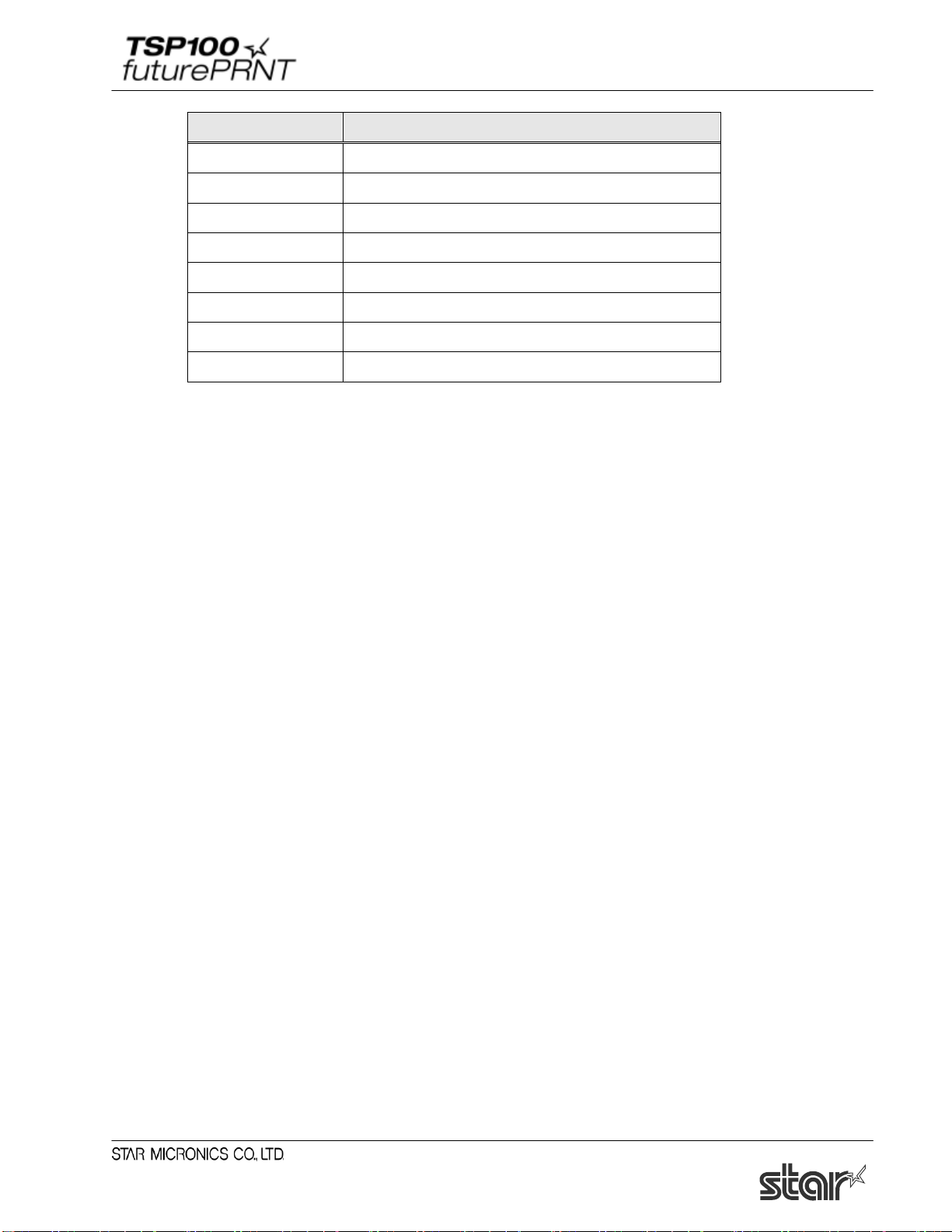
3.4.1. Control Font list
The following table is the list of the supported control device fonts.
Character Function
A Open cash drawer 1 for 50 mSec.
B Open cash drawer 1 for 100 mSec.
C Open cash drawer 1 for 150 mSec.
D Open cash drawer 1 for 200 mSec.
E Open cash drawer 1 for 250 mSec.
d Open cash drawer 2 for 200 mSec.
6 LF
7 CR
F Full Cut
P Partial Cut
a Set Left Alignment
b Set Center Alignment
c Set Right Alignment
e Set 3mm line feed spacing (1/8 inch)
f Set 4mm line feed spacing (1/6 inch)
g Select USA international character set
h Select France international character set
i Select Germany international character set
j Select England international character set
k Select Denmark I international character set
l Select Sweden international character set
m Select Italy international character set
n Select Spain I international character set
o Select Japan international character set
p Select Norway international character set
51
Page 57
Software Manual
Character Function
q Select Denmark II international character set
r Select Spain II international character set
s Select Latin America international character set
t Select turn over printing
u Cancel turn over printing
v Select the customer display
w Deselect the customer display
x Clear the customer display
Notes:
The settings above will be ignored if a specified control character is not supported by the
printer.
52
Page 58

Software Manual
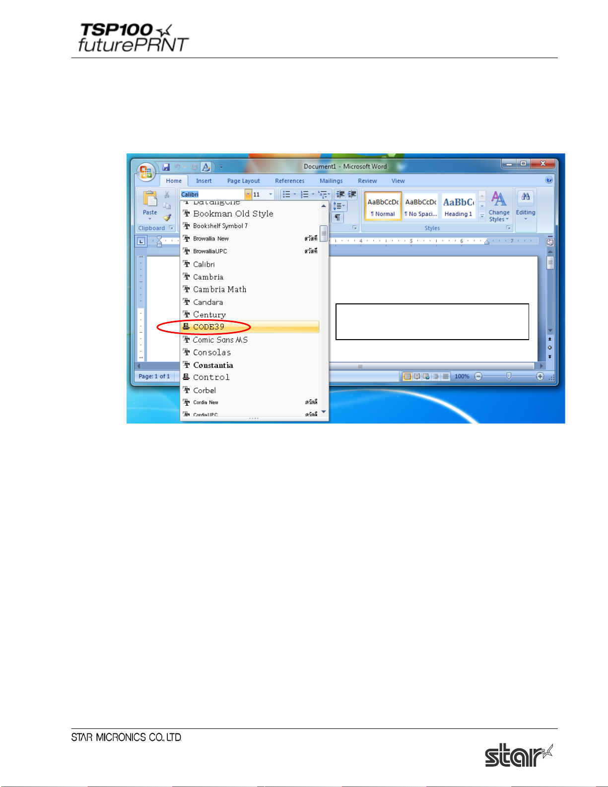
1. Choose the control font from
2. Enter the characters for the printer actions
The specified function is performed by
3.4.2. Control Font Usage
Usage of the Control font must be done as follows:
- Select Control Font
your editor’s font menu.
- Input Control Font
which you want to use.
printing.
Example;
Enter ‘A’: Open cash drawer 1 for 50 mSec.
Enter ‘P’: Partial Cut
Please set the control font's character size to the standard value (8.5 points).
53
Page 59

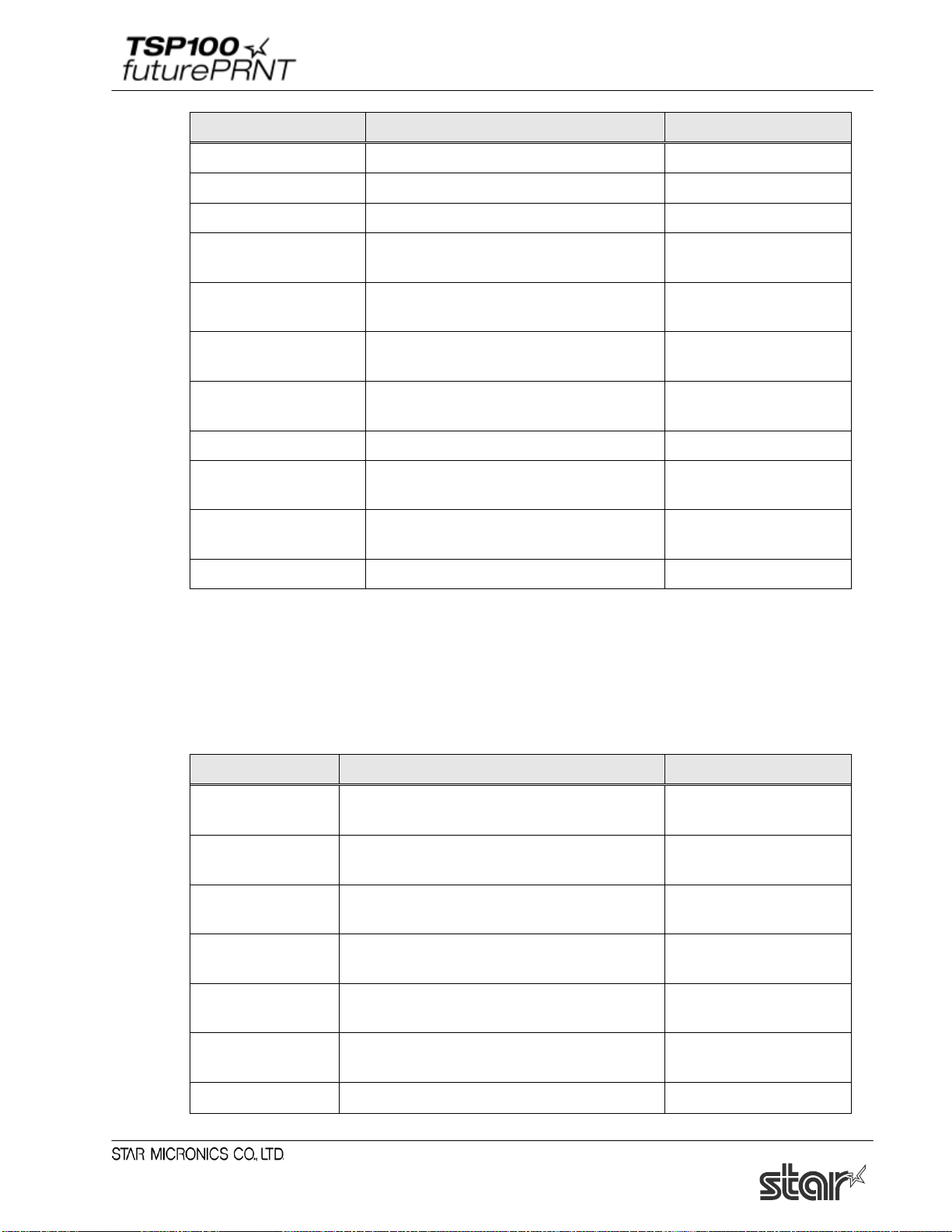
Software Manual
Barcode Type
Number of Characters
Character Set
UPC-E
12
0 - 9
UPC-A
12
0 - 9
JAN/EAN-8
8
0 - 9
JAN/EAN-13
13
0 - 9
CODE39
1 or more
0 - 9
-, ., <SP>, $, /, +, %
A - Z
Start / Stop: *
ITF
1 or more (even)
0 - 9
NW-7 (Codabar)
1 or more
0 - 9
-, $, :, /, ., +
A - D
3.5. Barcode Font
After printing Barcode, small characters are printed under barcode. But the barcode image data is
not displayed.
This action is only available when Print mode option is set to Line mode.
On Raster Mode, this setting is not available.
3.5.1. Barcode Font List
The following table is the lists of the supported barcode device fonts and usable characters.
* It is unnecessary to input Start and stop code since they are entered automatically.
3.5.2. Enter the Barcode font
Enter the barcode font character ‘z’ to terminate the barcode.
Example:
Using the CODE39 device font, enter as follows;
apABCDE67890z a p ABCDE67890 z
Input data
Terminate Barcode
Barcode Data
Single letter height code
Single letter width parameter
Each parameter refers to the list of Barcode font parameter on the next page.
54
Page 60

Software Manual
UPC-E, UPC-A,
JAN/EAN-8,
JAN/EAN-13
Barcode Device Font Parameter
Character
for Barcode
printing
Function
CODE39
NW-7
ITF
Details
a 2 dot 2 dot (6) 2 dot (5) Minimum module width
b 3 dot 3 dot (9) 4 dot (10) Minimum module width
c 4 dot 4 dot (12) 6 dot (15) Minimum module width
d N/A 2 dot (5) 2 dot (4) Minimum module width
e N/A 3 dot (8) 4 dot (8) Minimum module width
f N/A 4 dot (10) 6 dot (12) Minimum module width
g N/A 2 dot (4) 2 dot (6) Minimum module width
h N/A 3 dot (6) 3 dot (9) Minimum module width
i N/A 4 dot (8) 4 dot (12) Minimum module width
o heght: 32 dot (4 mm)
p heght: 64 dot (8 mm)
q heght: 96 dot (12 mm)
r heght: 128 dot (16 mm)
s heght: 160 dot (20 mm)
t heght: 192 dot (24 mm)
u heght: 224 dot (28 mm)
v heght: 255 dot (31.9 mm)
z Terminate Code (1Eh)
N/A = Not available
() numeral is dots for wide width.
55
Page 61
Software Manual
1. Choose the barcode device font from
3.5.3. Barcode Font Usage
Usage of the Barcode device font must be done as follows:
- Select Barcode Font
your editor’s menu
56
Page 62

Software Manual
2. Input code.
- Input Barcode font
The specified function is performed by
printing.
<Print result sample>
Please set the barcode device font's character size to the standard value (8.5
points).
57
Page 63

Software Manual
3.6. 2D Code Printing Function (2D Code Fonts)
The 2D code printing function performs QR code or PDF417 printing using device fonts supported in
this driver.
QR code or PDF417 printing is realized with a combination of 2D code fonts
(”QR_CNTL”, ”PDF417”, ”DATA1”, ”DATA2”, and ”DATA3”) and control fonts (”ESC_FONT”
and ”ESC_FONT_KANJI”).
Each Font Function as follows;
Device Font
Name
Function Details Memo
QR_CNTL
PDF417
DATA1
DATA2 \x20 - \x7F replace \x60 - \xBF
DATA3 \x20 - \x5F replace \xC0 - \xFF
ESC_FONT Output \x20 - \x7F
Setting
QR commands
Setting
PDF417
commands
Setting
2D code data
Output commands for QR
printing.
Output commands for PDF417
printing.
\x20 - \x7F replace \x00 - \x5F
3.6.1. Entering a 2D Code Font (QR Code)
Follow the steps below to describe a QR code.
(1) 2D code type setting
Only describe the parameters to be changed because the default value is set to each setting
item.
(2) 2D code data setting
Describe parameters and 2D code data following a 2D code data setting command.
(3) Obtaining 2D code expansion information (Option)
An error notification will be returned if any inconsistencies are detected in the settings made
in steps (1) and (2).
(4) 2D code printing
For information about commands, refer to the separate manual, “STAR Line Mode Command
Specifications".
Example: When generating a 2D code of "012345ABCD " with a QR code (correction rate:
25%):
Output \x00 -\xFF
is possible.
Output \x20 -\x7F
is possible.
58
Page 64

Software Manual
Description data: E2A0* 012345ABCDP
Description character Setting font Meaning
(1) ‘E2’ QR_CNTL Sets to correct errors level Q (25%).
(2) ‘AO’ QR_CNTL QR Code data setting (Automatic data analysis)
(2) ‘*’ DATA1 QR Code data setting parameter
A = ¥x0A = ‘*’ *1
(2) ‘ ’ DATA1 QR Code data setting parameter
0 = ¥x00 = ‘ ‘ (Space character) *1
(2) ‘012345ABCD’ ESC_FONT 2D code data
(4) ‘P’ QR_CNTL QR code printing
*1 Describe "0A", which indicates the number of bytes (10 bytes) of 2D code data in
hexadecimal notation, in the low-order byte (A) and high-order byte (0) respectively.
Printing result:
3.6.2. 2D Code Command Setting Font
QR code setting fonts (QR_CNTL)
QR_CNTL Fonts Function Output Code
0 Use for Parameter \x00
1 Use for Parameter \x01
2 Use for Parameter \x02
3 Use for Parameter \x03
4 Use for Parameter \x04
5 Use for Parameter \x05
6 Use for Parameter \x06
7 Use for Parameter \x07
8 Use for Parameter \x08
9 Use for Parameter \x09
M Set model of QR code \x1b\x1dyS0
59
Page 65
Software Manual
QR_CNTL Fonts Function Output Code
M1 Set model of QR code: Model 1 \x1b\x1dyS0\x01
M2 Set model of QR code: Model 2 \x1b\x1dyS0\x02
E Set up correct errors level \x1b\x1dyS1
* El (E0)
* Em (E1)
* Eq (E2)
* Eh (E3)
Correct errors level L
(correction rate: 7%)
Correct errors level M
(correction rate: 15%)
Correct errors level Q
(correction rate: 25%)
Correct errors level H
(correction rate: 30%)
\x1b\x1dyS1\x00
\x1b\x1dyS1\x01
\x1b\x1dyS1\x02
\x1b\x1dyS1\x03
S1~S8 Set module size (unit: dot) \x1b\x1dyS2 (\x01~08)
A0
B
QR code data setting
(automatic data analysis)
QR code data setting
(manual data analysis)
\x1b\x1dyD1\x00
\x1b\x1dyD2
P Print QR code data \x1b\x1dyP
*) The correct errors level can also be set using the correction rate enclosed by parentheses ().
PDF417 setting fonts (PDF417)
Character Function Driver-output code
0
command
Used for parameter of each PDF417 setting
Used for parameter of each PDF417 setting
1
command
Used for parameter of each PDF417 setting
2
command
Used for parameter of each PDF417 setting
3
command
Used for parameter of each PDF417 setting
4
command
Used for parameter of each PDF417 setting
5
6
command
Used for parameter of each PDF417 setting
\x00
\x01
\x02
\x03
\x04
\x05
\x06
60
Page 66
Software Manual
command
S
E
D
P
Character Function Driver-output code
7
8
9
M
A
Used for parameter of each PDF417 setting
command
Used for parameter of each PDF417 setting
command
Used for parameter of each PDF417 setting
command
Specifies the PDF417 code size.
Specifies the PDF417 security level (ECC).
Specifies the X-direction size of the PDF417
module.
Specifies the aspect ratio of the PDF417
module.
\x07
\x08
\x09
\x1b\x1dxS0
\x1b\x1dxS1
\x1b\x1dxS2
\x1b\x1dxS1
Specifies PDF417 code data. \x1b\x1dxS3
Prints a PDF417 code. \x1b\x1dxP
I
information.
Obtains PDF417 code expansion
\x1b\x1dx1
61
Page 67

Software Manual
Input Data
Output Data
On applications (Word, VB, etc),
user specified characters
Character
Code
ESC_FONT
DATA1
DATA2
DATA3
$
\x24
\x24
\x04
\x64
\xC4 % \x25
\x25
\x05
\x65
\xC5
&
\x26
\x26
\x06
\x66
\xC6
+
\x2B
\x2B
\x0B
\x6B
\xCB
,
\x2C
\x2C
\x0C
\x6C
\xCC
0
\x30
\x30
\x10
\x70
\xD0
1
\x31
\x31
\x11
\x71
\xD1
2
\x32
\x32
\x12
\x72
\xD2
3
\x33
\x33
\x13
\x73
\xD3
8
\x38
\x38
\x18
\x78
\xD8 9 \x39
\x39
\x19
\x79
\xD9
:
\x3A
\x3A
\x1A
\x7A
\xDA
=
\x3D
\x3D
\x1D
\x7D
\xDD
>
\x3E
\x3E
\x1E
\x7E
\xDE ? \x3F
\x3F
\x1F
\x7F
\xDF @ \x40
\x40
\x20
\x80
\xE0
E
\x45
\x45
\x25
\x85
\xE5 F \x46
\x46
\x26
\x86
\xE6
3.6.3. 2D Code Data Setting Font (DATA1, DATA2, DATA3, ESC_FONT)
Output code for printer
<SP> \x20 \x20 \x00 \x60 \xC0
! \x21 \x21 \x01 \x61 \xC1
“ \x22 \x22 \x02 \x62 \xC2
# \x23 \x23 \x03 \x63 \xC3
‘ \x27 \x27 \x07 \x67 \xC7
( \x28 \x28 \x08 \x68 \xC8
) \x29 \x29 \x09 \x69 \xC9
* \x2A \x2A \x0A \x6A \xCA
- \x2D \x2D \x0D \x6D \xCD
. \x2E \x2E \x0E \x6E \xCE
/ \x2F \x2F \x0F \x6F \xCF
4 \x34 \x34 \x14 \x74 \xD4
5 \x35 \x35 \x15 \x75 \xD5
6 \x36 \x36 \x16 \x76 \xD6
7 \x37 \x37 \x17 \x77 \xD7
; \x3B \x3B \x1B \x7B \xDB
< \x3C \x3C \x1C \x7C \xDC
A \x41 \x41 \x21 \x81 \xE1
B \x42 \x42 \x22 \x82 \xE2
C \x43 \x43 \x23 \x83 \xE3
D \x44 \x44 \x24 \x84 \xE4
62
Page 68
Software Manual
Input Data
Output Data
On applications (Word, VB, etc),
user specified characters
Character
Code
ESC_FONT
DATA1
DATA2
DATA3
G
\x47
\x47
\x27
\x87
\xE7
H
\x48
\x48
\x28
\x88
\xE8
I
\x49
\x49
\x29
\x89
\xE9
L
\x4C
\x4C
\x2C
\x8C
\xEC
M
\x4D
\x4D
\x2D
\x8D
\xED
N
\x4E
\x4E
\x2E
\x8E
\xEE O \x4F
\x4F
\x2F
\x8F
\xEF P \x50
\x50
\x30
\x90
\xF0
T
\x54
\x54
\x34
\x94
\xF4
U
\x55
\x55
\x35
\x95
\xF5 V \x56
\x56
\x36
\x96
\xF6 W \x57
\x57
\x37
\x97
\xF7
[
\x5B
\x5B
\x3B
\x9B
\xFB \ \x5C
\x5C
\x3C
\x9C
\xFC
]
\x5D
\x5D
\x3D
\x9D
\xFD
b
\x62
\x62
\x42
\xA2 - c
\x63
\x63
\x43
\xA3 - d
\x64
\x64
\x44
\xA4
-
g
\x67
\x67
\x47
\xA7 - h
\x68
\x68
\x48
\xA8 - i
\x69
\x69
\x49
\xA9 - j
\x6A
\x6A
\x4A
\xAA
-
o
\x6F
\x6F
\x4F
\xAF - p
\x70
\x70
\x50
\xB0 - q
\x71
\x71
\x51
\xB1
-
Output code for printer
J \x4A \x4A \x2A \x8A \xEA
K \x4B \x4B \x2B \x8B \xEB
Q \x51 \x51 \x31 \x91 \xF1
R \x52 \x52 \x32 \x92 \xF2
S \x53 \x53 \x33 \x93 \xF3
X \x58 \x58 \x38 \x98 \xF8
Y \x59 \x59 \x39 \x99 \xF9
Z \x5A \x5A \x3A \x9A \xFA
^ \x5E \x5E \x3E \x9E \xFE
_
` \x60 \x60 \x40 \xA0 -
a \x61 \x61 \x41 \xA1 -
e \x65 \x65 \x45 \xA5 -
f \x66 \x66 \x46 \xA6 -
k \x6B \x6B \x4B \xAB -
l \x6C \x6C \x4C \xAC -
m \x6D \x6D \x4D \xAD -
n \x6E \x6E \x4E \xAE -
\x5F \x5F \x3F \x9F \xFF
63
Page 69

Software Manual
Input Data
Output Data
On applications (Word, VB, etc),
user specified characters
Character
Code
ESC_FONT
DATA1
DATA2
DATA3
r
\x72
\x72
\x52
\xB2
-
s
\x73
\x73
\x53
\xB3
-
t
\x74
\x74
\x54
\xB4
-
w
\x77
\x77
\x57
\xB7
-
x
\x78
\x78
\x58
\xB8
-
y
\x79
\x79
\x59
\xB9 - z
\x7A
\x7A
\x5A
\xBA - {
\x7B
\x7B
\x5B
\xBB
-
.
\x7F
\x7F
\x5F
\xBF
-
Output code for printer
u \x75 \x75 \x55 \xB5 -
v \x76 \x76 \x56 \xB6 -
| \x7C \x7C \x5C \xBC -
} \x7D \x7D \x5D \xBD -
~ \x7E \x7E \x5E \xBE -
* Cannot be entered using a character.
64
Page 70

Software Manual
3.6.4. 2D Code Font Usage
QR code can be specified up to 500 bytes. (It includes input data and punctuated marks in
500bytes.) Sample programs of Visual Basic using 2D code is as follows;
QR Code Print Sample1:
Private Sub Command1_Click()
Printer.Font.Name = "Printer 17cpi Tall
Printer.Print "QR Code Test Print for VB 6.0"
Printer.Font.Name = "Printer 17cpi"
Printer.Print
Printer.Print "DATA:"
Printer.Print "http://www.star-m.jp/"
Printer.Print
Printer.Print "QR code:";
Printer.Font.Name = "QR_CNTL" ' QR_CNTL font setting
Printer.Print "M2"; ' Bar code model setting
Printer.Print "Em"; ' Error correction level setting (correction rate: 15%)
Printer.Print "S3" ' Module size setting (size: 3 dot)
Printer.Print "B1"; ' Bar code data setting (manual data analysis) + number of blocks
Printer.Print "2"; ' Alphanumeric characters (data type)
Printer.Font.Name = "DATA1" ' DATA1 = 0x0000 - 0x005F
Printer.Print Chr(&H35); '
Printer.Print Chr(&H20); '
Printer.Font.Name = "ESC_FONT" ' ESC_FONT = 0x0020 - 0x007F
Printer.Print "http://www.star-m.jp/"; ' Bar code data (21 bytes)
Printer.Font.Name = "QR_CNTL" ' QR_CNTL font setting
Printer.Print "P" ' Printed characters for bar code data
Printer.EndDoc
End Sub
Change 0x35 → 0x15, 0x20 → 0x0
Number of bytes: 21 (0x15) + 0 (0x0) = 21 bytes
When the QR code data set t i ng i s set t o manual data analysis, be sure to set the
number of block s and the entered data type.
For information on the setting method, refer to the separ ate manual “STAR Line
Mode Command Specification s”.
65
Page 71

Software Manual
QR Code Print Sample2:
Private Sub Command2_Click()
Printer.Font.Name = "Printer 17cpi Tall"
Printer.Print "QR Code Test Print for VB 6.0"
Printer.Font.Name = "Printer 17cpi"
Printer.Print
Printer.Print "DATA:"
Printer.Print "http://www.star-m.jp/"
Printer.Print
Printer.Print "QR code:";
Printer.Font.Name = "QR_CNTL" ' QR_CNTL font setting
Printer.Print "M1"; ' Bar code model setting
Printer.Print "Eq"; ' Error correction level setting (correction rate: 25%)
Printer.Print "S7" ' Module size setting (size: 7 dot)
Printer.Print "A0"; ' Bar code data setting (automatic data analysis)
Printer.Font.Name = "DATA1" ' DATA1 = 0x0000 - 0x005F
Printer.Print Chr(&H35); '
Printer.Print Chr(&H20); '
Printer.Font.Name = "ESC_FONT" ' ESC_FONT = 0x0020 - 0x007F
Printer.Print "http://www.star-m.jp/"; ' Bar code data (21 bytes)
Printer.Font.Name = "QR_CNTL" ' QR_CNTL font setting
Printer.Print "P" ' Printed characters for bar code data
Printer.EndDoc
End Sub
Change 0x35 → 0x15, 0x20 → 0x0
Number of bytes: 21 (0x15) + 0 (0x0) = 21 bytes
66
Page 72

Software Manual
■ PDF417 printing - Sample 1
Private Sub Command4_Click()
Printer.Font.Name = "Printer 17cpi Tall"
Printer.Print "PDF417 Test Print for VB 6.0"
Printer.Font.Name = "Printer 17cpi"
Printer.Print
Printer.Print "DATA:"
Printer.Print "1234567890"
Printer.Print
Printer.Print "PDF417: ";
Printer.Font.Name = "PDF417"
Printer.Print "S023"; ' Specifies the barcode size.
Printer.Print "E3"; ' Specifies the ECC level.
Printer.Print "M3" ' Specifies the X-direction size of the PDF417 module.
Printer.Print "A3" ' Specifies the aspect ratio of the PDF417 module.
Printer.Print "D"; ' Specifies bar code data.
Printer.Font.Name = "DATA1" ' DATA1 = 0x0000 - 0x005F
Printer.Print Chr(&H2A); '
Printer.Print Chr(&H20);
Printer.Font.Name = "ESC_FONT" ' ESC_FONT = 0x0020 - 0x007F
Printer.Print "1234567890";
Printer.Print.Name = "PDF417"
Printer.Print "P" ' Prints bar code data.
Printer.EndDoc
End Sub
Specifies the number of barcode data bytes.
67
Page 73

Software Manual
■ PDF417 printing - Sample 2
Private Sub Command5_Click()
Printer.Font.Name = "Printer 17cpi Tall"
Printer.Print "PDF417 Test Print for VB 6.0"
Printer.Font.Name = "Printer 17cpi"
Printer.Print
Printer.Print "DATA:"
Printer.Print " http://.star-m.jp/"
Printer.Print
Printer.Print "PDF417:";
Printer.Font.Name = "PDF417"
Printer.Print "S023"; ' Specifies the barcode size.
Printer.Print "E3"; ' Specifies the ECC level.
Printer.Print "M3" ' Specifies the X-direction size of the PDF417 module.
Printer.Print "A3" ' Specifies the aspect ratio of the PDF417 module.
Printer.Print "D"; ' Specifies bar code data.
Printer.Font.Name = "DATA1" ' DATA1 = 0x0000 - 0x005F
Printer.Print Chr(&H31); '
Printer.Print Chr(&H20);
Printer.Font.Name = "ESC_FONT" ' ESC_FONT = 0x0020 - 0x007F
Printer.Print "http://.star-m.jp/";
Printer.Print.Name = "PDF417"
Printer.Print "P" ' Prints bar code data.
Printer.EndDoc
End Sub
Specifies the number of barcode data bytes.
68
Page 74
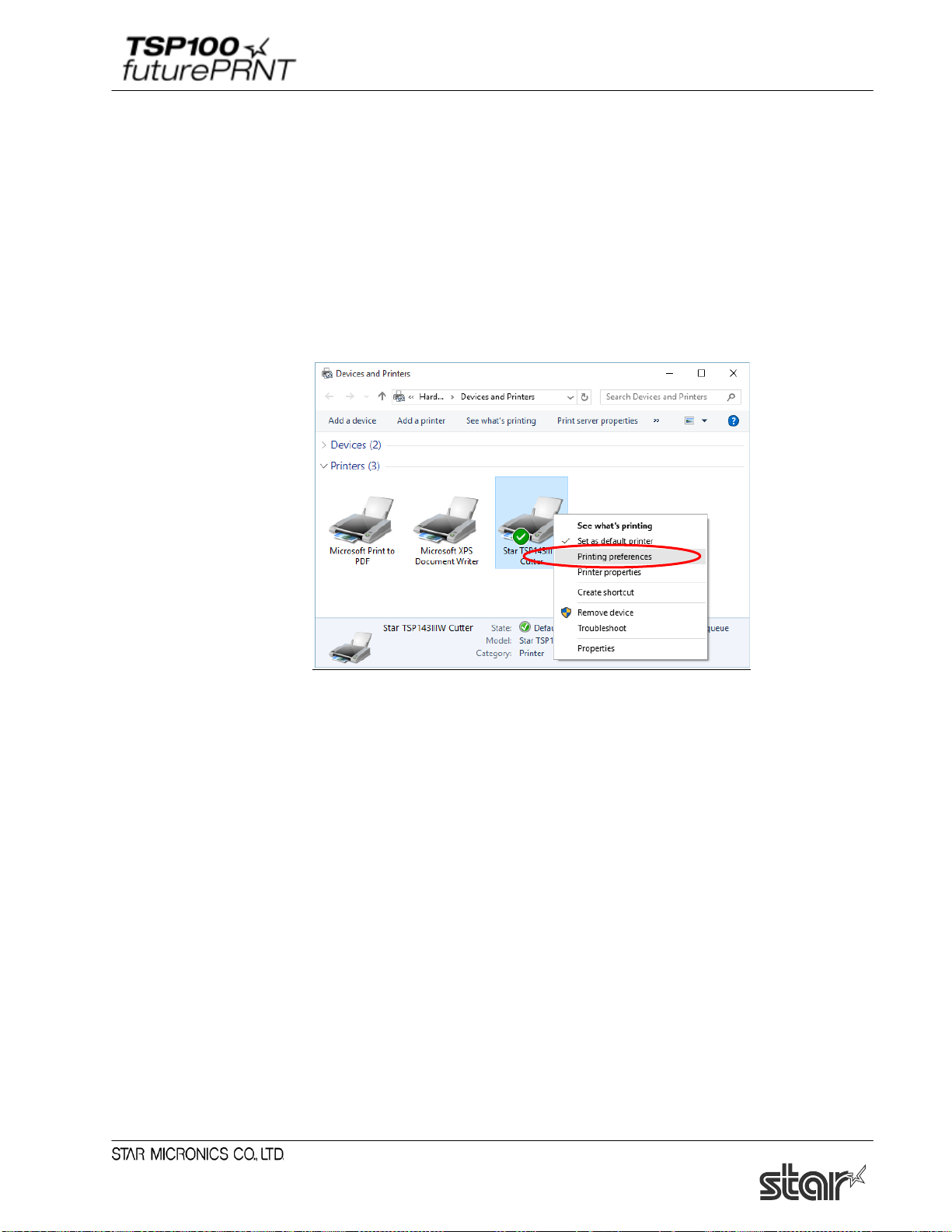
Software Manual
3.7. 2-Tone Color Printing and Paper Type Settings
This driver supports two-tone color printing.
To perform two-tone color printing and use special paper, load the appropriate thermal paper in the
printer, and configure the following setting.
(1) In Control Panel, select “Devices and Printers”.
(2) Right-click on the icon of the target printer queue, and select “Printing preferences” in the
pull-down menu.
69
Page 75
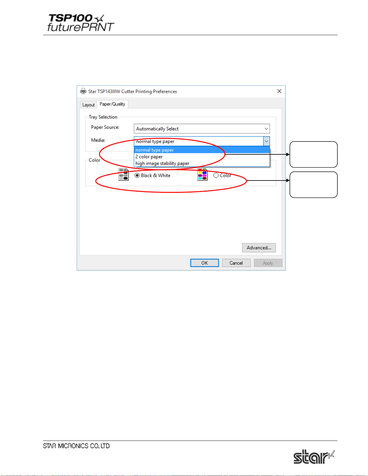
Software Manual
Select paper
Specify print
(3) When the “Printing Preferences ... ” window opens, click the “Paper/Quality” tab. Then,
select the type of paper that suits the print color that has been specified.
Paper Type and Print Color Configuration Window
type
color
For normal gray scale printing
For gray scale printing on normal thermal paper, select the following:
Media : Select “normal type paper”
Color : Select “black and white” check button
For two-tone color printing
For color printing on two-tone thermal paper, select the following:
Media : Select “2 color paper”
Color : Select “color” check button
For printing on special paper
When you need to print darker than normal gray scale, or use special paper such as high image
stability paper, select the following:
Media : Select “high image stability paper”
Color : Select “black and white” check button
70
Page 76

Software Manual
4. TSP100 Configuration Application
The TSP100 configuration application lets you control the look and content of printed receipts.
You can set up separate configurations for Star Line mode and for ESC/POS mode.
Notes:
TSP100 configuration application settings require computer administrator privileges.
There are the following two methods to launch the TSP100 configuration application.
● Using the Windows Start menu
Select “Programs, All Programs or All Apps” - “StarMicronics” - “Star TSP100” “Configuration Utility”, and proceed to step (4).
In Windows 8.1 and 8: Select [Configuration Utility TSP100] tile.
● Using Properties of the printer
(1) In Control Panel, select “Devices and Printers”.
(2) Right-click on the icon of the target printer queue. Then, in the pull-down menu, select
“Printer Properties”.
71
Page 77
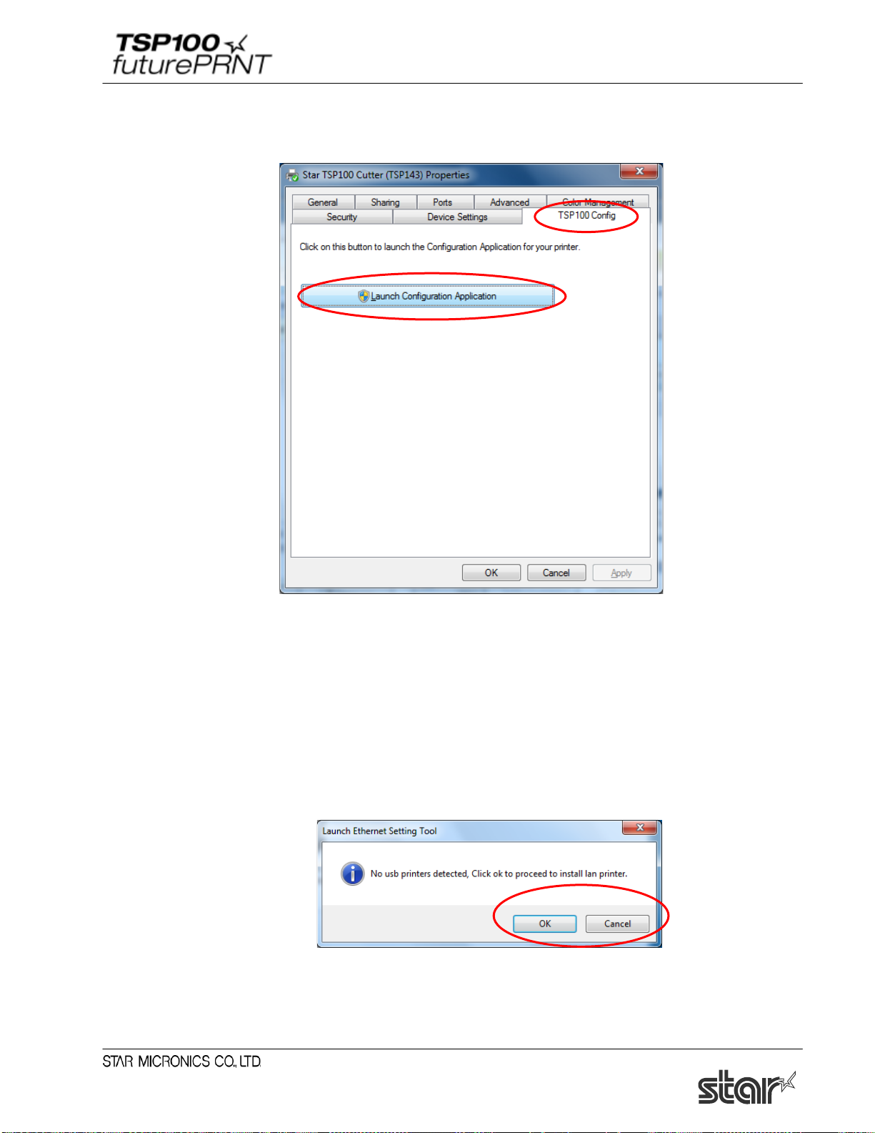
Software Manual
(3) Click “Launch Configuration Application” in the "TSP100 Config" tab.
(4) The "User Account Control" window will appear. Click "Yes".
(5) When the LAN function is installed with the standard setup, if an available printer is not
found, the following window will appear.
When using the TSP100LAN, click “OK” to start the Ethernet setup tool, and add the
required printer, referring to "1.3 Adding a Printer (TSP100LAN)", “1.4 Adding a
Printer(TSP100IIIW)” or “1.5 Adding a Printer(TSP100IIILAN)”.
When using a non-TSP100LAN printer, click “Cancel” to stop the procedure, and add the
required printer, referring to "1.2 Adding a Printer (TSP100U/PU/GT/ECO)".
72
Page 78

Software Manual
(6) If the application is launched from the Start menu while there are multiple available printer
queues, the following window will appear. Select a target printer, and click “OK”.
If the LAN function is installed, you can select the "Add TSP100LAN" checkbox to start the
Ethernet setup tool.
(7) Select a target emulation, and click “OK”.
(8) The "TSP100 Configuration" window will be opened.
IMPORTANT: After changing any setting in the "TSP100 Configuration" window, be
sure to click “Apply Changes”.
The changed setting is enabled by clicking “Apply Changes”.
73
Page 79

Software Manual
4.1. Menu Functions
The menu bar in the “TSP100 Configuration” contains the “File”, “View”, “ECO”, “Management”
and “Help” menus. Each menu is explained on the following pages.
4.1.1. File
1. Export
The settings made using the “TSP Configuration” can be saved. The settings are saved as a
file with an “.xml” extension.
2. Import
Previously saved settings made using the “TSP Configuration” can be imported. Import the
file with the “.xml” extension, and then click “Apply”.
Note:
1. The settings for the Star Line mode and ESC/POS mode are saved separately. When
importing the settings, confirm the selected mode, and then import the settin g file.
2. The following settings made using the “TSP Configuration” cannot be imported or
exported.
• Star Cloud Services
• OPOS
• JavaPOS
• Serial ports
• Virtual TCP/IC port
• Settings in “3. Windows Printer Driver Usage”
74
Page 80

Software Manual
When importing data using an operating system or user different from that for
exporting data, execute the following steps to use the HexDump mode, ECO
settings - on-demand function, and journal function.
HexDump Mode
1. Change the folder where to save data in the HexDump mode setting window.
2. Click “Set”.
ECO settings - on-demand function
1. In the ECO Settings window, clear the "Enable on demand" checkbox once.
2. Select the "Enable on demand" checkbox again.
3. Click “Apply Changes”.
Journal function
1. In the Journal and Multi-Copy window, clear the "Enable Journal" checkbox once.
2. Select the "Enable Journal" checkbox again.
3. Click “Apply Changes”.
75
Page 81
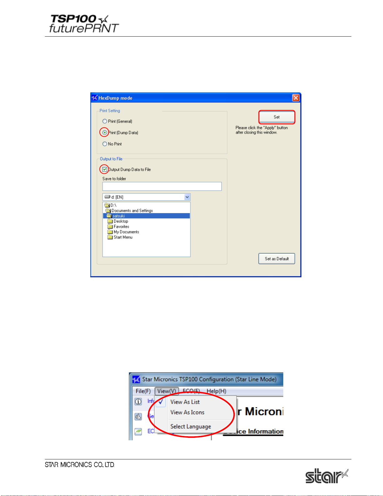
Software Manual
3. HexDump Mode
All of the data transmitted to the printer from the computer is printed or output as a file using
hexadecimal code.
The data transmitted to the printer can be checked for correctness and the causes of errors can
be investigated.
4.1.2. View
Print [Dump Data]
All of the data transmitted to the printer from the computer is printed using hexadecimal
code.
Output Dump Data to File
All of the data transmitted to the printer from the computer is output as hexadecimal
binary data in a file to the specified folder.
Note: To apply the setting, click “Set”, and then click “Set” in the utility screen.
76
Page 82
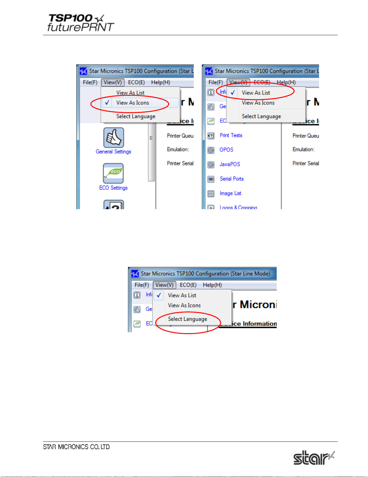
Software Manual
1. List display/Icon display
The setting items for the “TSP Configuration” can be displayed as a list or as icons.
2. Language selection
The display language can be selected.
STEP 1:
On the “View” menu, select “Language selection” to display the list of available languages.
77
Page 83

Software Manual
STEP 2:
Select the language, and then click “Select”.
4.1.3. ECO
STEP 3:
Click “Select”, and then temporarily close the “TSP Configuration”. By opening the “TSP
Configuration” again, the selected language will be displayed.
Note: If the characters are corrupted, change the settings in the Advanced tab in Regional
Options in Control Panel in Windows.
When using the printer with the ECO settings, the percentage of paper saved can be confirmed by
enabling this function.
78
Page 84
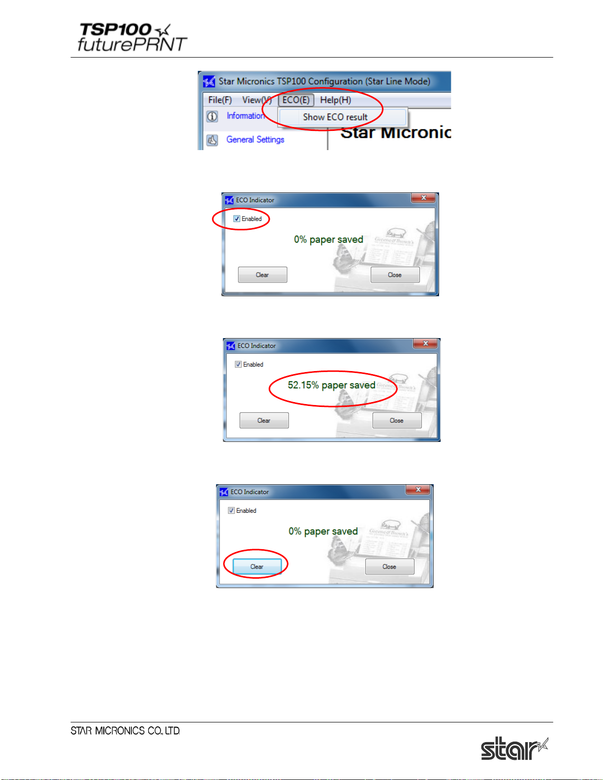
Software Manual
1. ECO indicator setting
Select "Enabled" checkbox in the "ECO Indicator" window to start measurement.
2. Check the result.
After printing, open the "ECO Indicator" window again to check the result.
3. Clear the accumulated result.
Click “Clear” to clear the accumulated result.
79
Page 85

Software Manual
4.1.4. Management
This is used to record logs and identify causes when communication errors occur.
4.1.5. Help
The software version can be confirmed using the “Help” menu.
80
Page 86

Software Manual
4.2. Information
The Information window displays device information of the printer to be configured.
81
Page 87
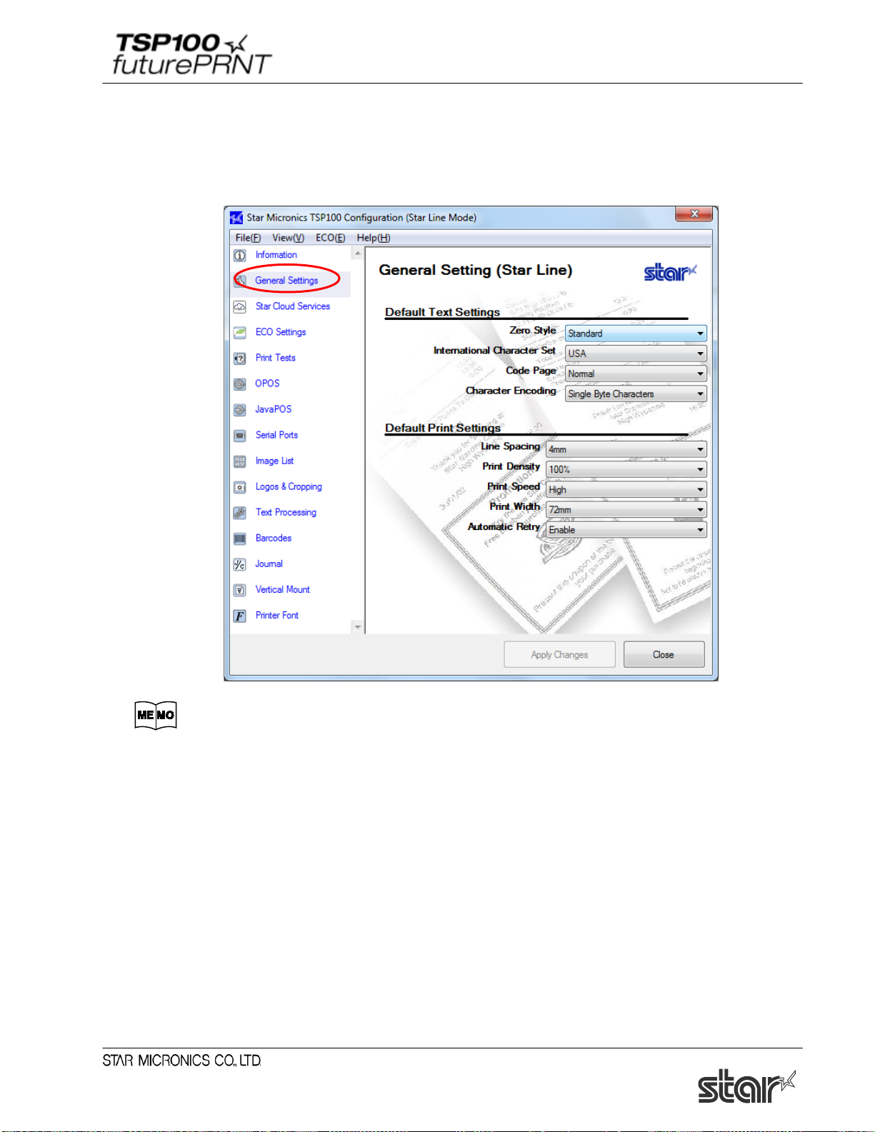
Software Manual
4.3. General Settings
Click the "General Settings" tab in the left pane of the window.
When the printer driver is used for printing, text and line spacing settings are
available only when device fonts are used.
82
Page 88
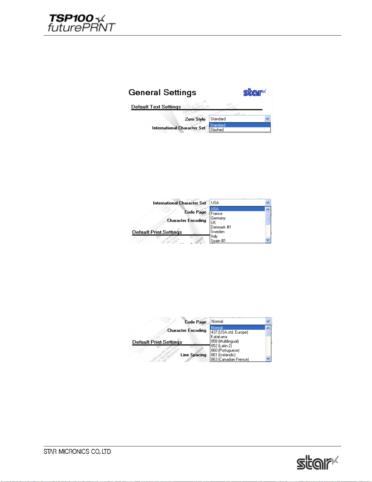
Software Manual
4.3.1. Default Text Settings
■ Zero Style
The default zero style is "Standard".
Selects whether the printer prints zeros in non-slashed form or slashed form. Select either
“Standard” (O) or “Slashed” (Ø).
■ International Character Set
■ Code Page
The default international character set is "USA".
Changing the international character set will change certain characters in the character table to
match those characters fitting the selected location. Typically the changes are accented characters
and currency symbols.
The default code page is "Normal" in the Star Line mode and " ESC/POS 437(USA,std. Europe)"
in the ESC/POS mode.
Changing the code page offers additional special characters specific to each of the specified
languages.
83
Page 89

Software Manual
■ Character Encoding
The default character encoding is "Single Byte Characters".
Selects the character encoding used by the printer. You can select either single-byte encoding
(common for all non-Asian languages) or any of the four available double-byte encodings (for the
corresponding Asian languages).
■ Font Type <ESC/POS mode only>
Standard: (the default): Selects the standard font.
Large: Selects a rounder, bulkier-looking font.
If "Large" is specified for "Font type", a larger text is created based on a font
design, and it looks a little tight because the character space is the same as for
the standard font type.
■ Character space (Right) <ESC/POS mode only>
0 (the default) to 3 dots
Use this feature to add extra space (in dot units) to the right of each character. Extra spacing may
improve appearance when you are using the Large font type.
4.3.2. Default Print Settings
■ Line Spacing
The default line spacing is "4 mm".
If the spacing is set to 4 mm (the initial setting), the printer will add a 1-mm line space between each 3-
84
Page 90
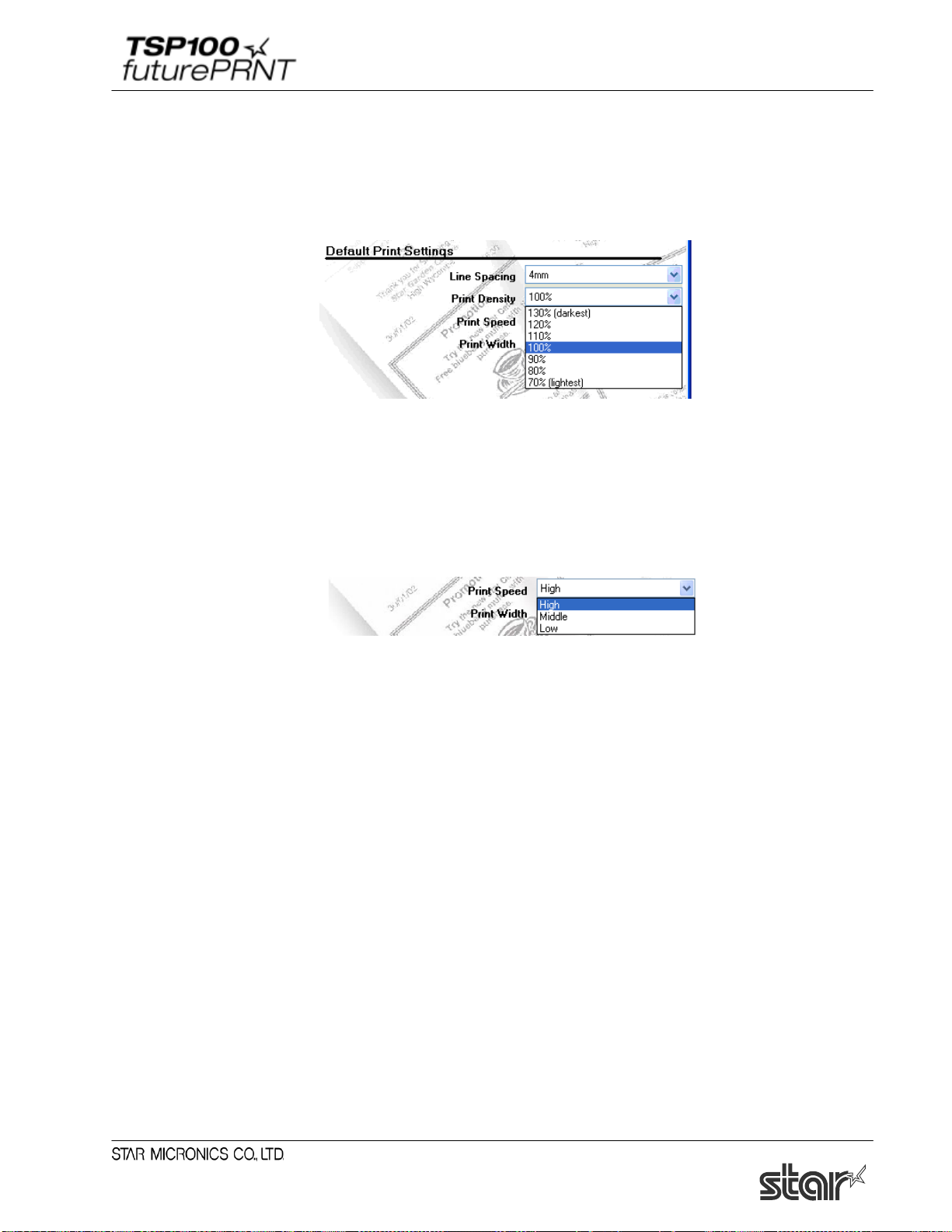
Software Manual
mm-tall line of characters. If the spacing is set to 3 mm, the added spacing is omitted and receipts are
correspondingly shorter. But note that the shorter receipts may be harder to read.
■ Print Density
Adjusting the print density allows for adjustment in the level of contrast to compensate for the different
levels of sensitivity of different types and grades of thermal paper. The recommended setting is 100%
(Default).
■ Print Speed
Depending on the application, it may be desirable to slow down the speed of printing. This is typically
done to adjust the quality of print based on the grade and type of paper used. The recommended
settings for most cases “High” (Default).
85
Page 91

Software Manual
■ Print Width
The print width should be set according to the size of paper used. The default (recommended
print width) is 72 mm.The standard default print width is 72 mm, which provides 4-mm margins
on both sides of 80-mm paper. The 51-mm print width setting is appropriate if you are using the
optional 58-mm paper supported by the TSP100 futurePRNT.
Notes:The print width is automatically changed to fit the paper width specified at addition
of the OPOS POS printer.
After changed automatically, do not adjust the print width manually.
■ Automatic Retry
If a printing error occurs while "Automatic Retry" is set to "Enable", the sent data is resent from
the beginning.
Retry processing is repeated up to five times.
The default is "Enable" for TSP100U/PU/LAN/ECO, and "Disabled" for TSP100GT.
Note:
1 If "Automatic Retry" is set to "Disabled", the ETB command is enabled in the
application side. However, check that the ETB is returned for one job before sending
the next print data. If print data is sent simultaneously from multiple PCs, the ETB
will not be guaranteed.
2 In t he ESC/POS mode, the ETB command is not available even if "Automatic Retry"
is disabled.
3 The automatic retry function is not available for OPOS, JavaPOS, virtual serial port,
and virtual TCP/IP port.
■ Characters/Line (font A ) <ESC/ POS mode only>
42 char. (default): The standard for ESC/POS mode.
48 char.: The standard for Star Line mode.
86
Page 92

Software Manual
■ Resolution Pitch <ESC/POS mode only>
Star Line standard: Uses Star Line mode’s standard resolution. (Characters are smaller than on
true ESC/POS printers, so the printer receipt is smaller and the right margin is larger.)
ESC/POS compatible (default): Margins and line widths are the same as on a typical ESC/POS
printer. (Characters are the same size as with Star Line standard, but padding is added so that
printer area occupies the same area as on a true EPSON/POS printer.)
Using this function, you can use legacy software solutions with no change.
If "Star standard" is selected, the pitch value is not adjusted.
87
Page 93

Software Manual
4.4. Star Cloud Services
Click the Star Cloud Services tab on the left side of the dialog box.
To use the Star Cloud Services, it is required to register a Star Cloud Services account in advance.
Please click “Here” for details.
88
Page 94

Software Manual
4.4.1. Device Registration
Register the device (futurePRNT series printer queue) using your registered Star Cloud Services
account.
Once you have registered the device, you can use the service of uploading print data to the cloud server
and manage the registered device from the Star Cloud Services dashboard.
(1) Enter the username and the password of your registered Star Cloud Services account and click
“Register Device”.
(2) The following dialog appears. Click OK.
(3) When the device is registered successfully, the account information of the connected Star
Cloud Services appears.
You can change the device name by connecting the dashboard with the registered account from
“Connect to Dashboard Website”. When the device name is changed, click to update the
device information on the screen.
Note: To change the account used for the device registration, please uninstall the driver utility and
re-install it.
89
Page 95
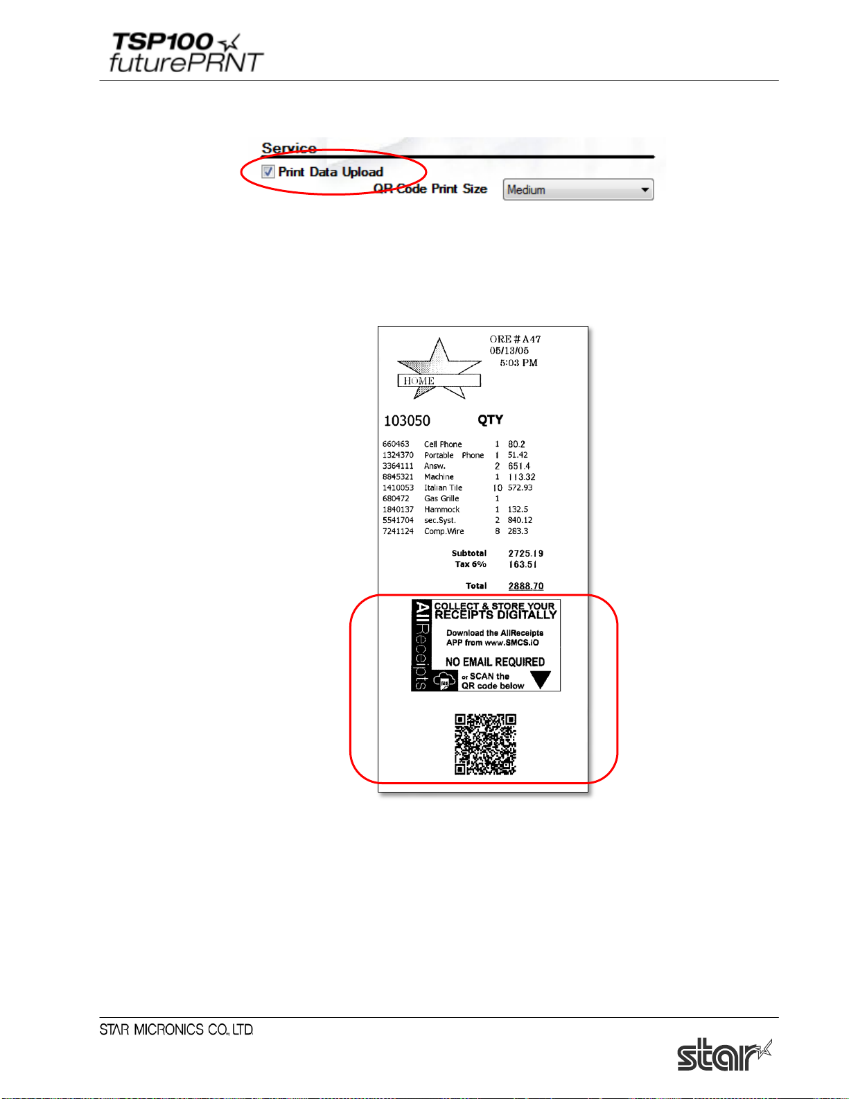
Software Manual
4.4.2. Setting of Registration
When “Print Data Upload” is checked, the QR code is added on the receipt and the data of printed
receipt is uploaded on the Star Cloud Server.
The print size of QR code can be specified.
Print Sample)
Note: To upload data on the Star Cloud Server, the host device must be connected to the network.
Please note that data may not be uploaded on the Star Cloud Server even though a QR code
is added on the receipt depending on the condition of network connection.
90
Page 96
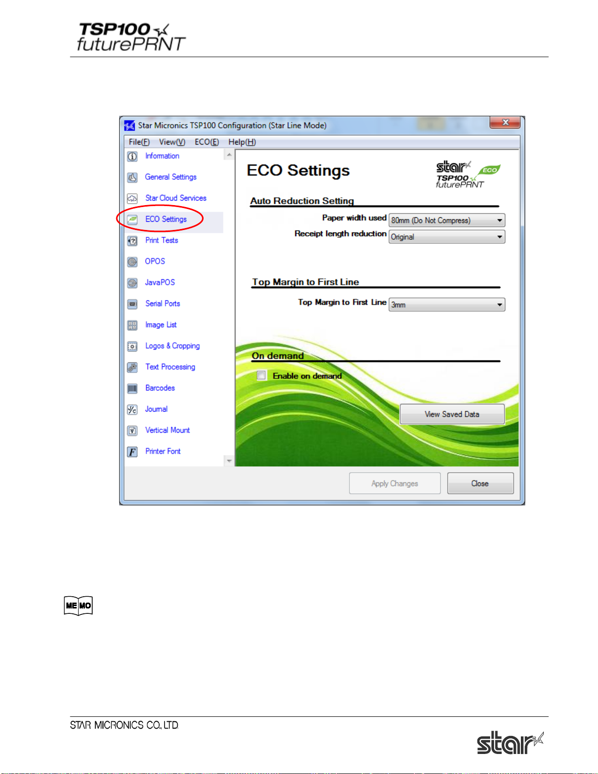
Software Manual
4.5. ECO Settings
Click the ECO Settings tab on the left side of the dialog box.
4.5.1. Auto Reduction Setting
This function reduces the overall size of the printing.
However, to prevent any scanning errors, the size of printed barcodes is not reduced
even if the reduction settings are selected.
91
Page 97

Software Manual
■ Paper width used
The default setting is “80mm (Do Not Compress)”.
By changing the setting to 80mm->58mm, the printing area is compressed widthwise so that 58 mm
width roll paper can be used instead of 80 mm width roll paper.
1) If the print ing widt h is set to 51 mm using General Settings in the configuration
utility, the 80mm->58mm setting in Paper width used is disabled.
2) When Paper width used is set to 80mm->58mm, the barcode will be aligned on the
left margin of the paper when printed. If the printed barcode will be wider than
80mm->58mm, the barcode data will not be printed.
■ Receipt length reduction <TSP100ECO only>
The default setting is Original (no reduction).
The printing area can be compressed 50% reduction or 25% reduction lengthwise.
Because the size of printed barcodes is not reduced even if the receipt length
reduction settings are selected, the receipt length will be longer than the length for the
reduction ratio when printing data that contains barcodes.
4.5.2. Top Margin to First Line <TSP100ECO only>
The length from the leading edge of the paper to the first line of printing can be specified.
92
Page 98
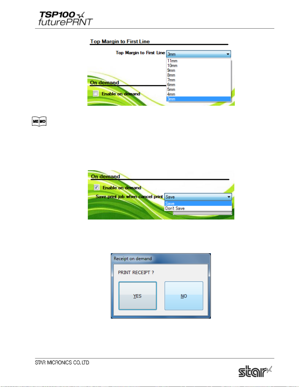
Software Manual
The default setting is 3mm.
We recommend 3 mm as being effective for the ECO function; however, backward
feeding is carried out for each cut operation when 10 mm or fewer is specified. To
reduce the printing time, set to 11 mm.
4.5.3. On demand
This function reduces the amount of paper wasted on unnecessary printings by prompting the user to
select whether or not to print the data.
■ Enable on demand
To enable the on demand function, select the check box. When the on demand function is enabled, the
following confirmation dialog box will appear each time data is sent from the computer to the printer.
When YES is clicked, the data will be printed.
When NO is clicked, the printing will be canceled.
93
Page 99
Software Manual
Normally, the confirmation dialog box appears before the data is printed. However, in
rare cases, the confirmation dialog box may not appear, the dialog box may appear
after the data is printed, or other problems with the operation of the function may occur.
If any of these problems occur, restart your computer. After restarting the computer,
check that the on demand function is enabled and that the confirmation dialog box
appears at the proper time.
■ Saving Canceled Data
When the on demand function is enabled, the data for the canceled printing can be saved or deleted.
When Don’t Save is selected, the data for the canceled printing will be deleted.
When Save is selected, the data for the canceled printing will be saved in the following folder.
<System Drive>\Star\TSP100\Ondemand
Note: When the driver utility application is updated from future PRNT CD 5.5 or earlier, the stored
data for canceled printing is transferred to the above folder.
If data has not been transferred to the above folder, please check the following folder.
Hard Disk Drive:\User\< Folder for logged-on user name >\APPData\
Roaming\Star\TSP100\Ondemand
1) To check the data saved in the folder above, perform the following setting before
viewing the data. At the Windows Start menu, select Control Panel → Folder Options,
click the View tab, and then click Show hidden files and folders.
2) The data saved in the folder is not deleted automatically regardless of the elapsed
time. Therefore, it is recommended to periodically delete any unnecessary data.
94
Page 100
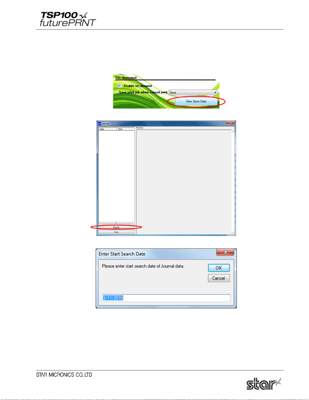
Software Manual
■ View Save Data
The data for canceled printings can be viewed. In addition, to print data that was saved from a
canceled printing, perform the following procedure.
(1) Click View Save Data.
(2) The Journal tool window appears. Click “Search” to search for the saved data.
(3) Enter the date to start searching, and click “OK”.
95
 Loading...