

Page 1

THERMAL PRINTER
TSP1000 SERIES
USER’S MANUAL
MODE D’EMPLOI
BEDIENUNGSANLEITUNG
MANUALE DI ISTRUZIONI
Page 2

Federal Communications Commission
Radio Frequency Interference
Statement
This device complies with Part 15 of the FCC Rules. Operation is subject to the following two
conditions: (1) This device may not cause harmful interference, and (2) this device must
accept any interference received, including interference that may cause undesired operation.
NOTE: This equipment has been tested and found to comply with the limits for a Class A
digital device, pursuant to Part 15 of the FCC Rules. These limits are designed to provide
reasonable protection against harmful interference when the equipment is operated in a
commercial environment. This equipment generates, uses and can radiate radio frequency
energy and, if not installed and used in accordance with the instruction manual, may cause
harmful interference to radio communications. Operation of this equipment in a residential
area is likely to cause harmful interference in which case the user will be required to correct
the interference at his own expense.
This statement will be applied only for the equipments marketed in U.S.A.
FCC WARNING
Changes or modifications not expressly approved by the party responsible for compliance
could void the user’s authority to operate the equipment.
For compliance with the Federal Noise Interference Standard, this equipment requires a
shielded cable.
For RF interference suppression, if a ferrite core is provided with this device, affix it to the
interface cable.
The Canadian Department of Communications
Statement of
Radio Interference Regulations
This Class A digital apparatus complies with Canadian ICES-003.
Cet appareil numérique de la classe A est conforme à la norme NMB-003 du Canada.
The above statement applies only to printers marketed in Canada.
Trademark acknowledgments
TSP1000: Star Micronics Co., Ltd.
ESC/POS: Seiko Epson Corporation
Notice
• All rights reserved. Reproduction of any part of this manual in any form whatsoever,
without STAR’s express permission is forbidden.
• The contents of this manual are subject to change without notice.
• All efforts have been made to ensure the accuracy of the contents of this manual at the
time of going to press. However, should any errors be detected, STAR would greatly
appreciate being informed of them.
• The above notwithstanding, STAR can assume no responsibility for any errors in this
manual.
©
Copyright 2004-2009 Star Micronics Co., Ltd.
Page 3

TABLE OF CONTENTS
1. Unpacking and Installation .......................................................................................... 1
1-1. Unpacking .......................................................................................................................... 1
2. Parts Identification and Nomenclature ....................................................................... 2
3. Consumable Parts and AC Adapter ............................................................................ 4
4. Connecting Cables and AC Adapter ........................................................................... 6
4-1. Interface Cable ................................................................................................................... 6
4-2. Connecting to a Buzzer Drive .......................................................................................... 10
4-3. Connecting the Optional AC Adapter .............................................................................. 11
4-4. Turning Power On ........................................................................................................... 12
4-5. Installing the Cable .......................................................................................................... 13
4-6. Switch Blind Installation ................................................................................................. 14
5. Control Panel and Other Functions ........................................................................... 15
5-1. Control Panel ................................................................................................................... 15
5-2. Errors ............................................................................................................................... 15
5-3. Self Printing ..................................................................................................................... 17
6. Loading the Roll Paper ............................................................................................... 18
6-1. Loading the Roll Paper .................................................................................................... 18
6-2. Paper Loading Methods ................................................................................................... 21
6-3. Roll Paper Holder Adjustment ......................................................................................... 22
6-4. Paper Guide Adjustment .................................................................................................. 23
6-5. Upper Guide Adjustment ................................................................................................. 24
7. Adjusting the Near-end Sensor .................................................................................. 25
8. Preventing and Clearing Paper Jams ........................................................................ 27
8-1. Preventing Paper Jams ..................................................................................................... 27
8-2. Removing Paper Jam ....................................................................................................... 27
8-3. Releasing a Locked Cutter ............................................................................................... 28
9. Periodical Cleaning ..................................................................................................... 30
9-1. Cleaning the Thermal Head ............................................................................................. 30
9-2. Cleaning the Paper Holder ............................................................................................... 30
Appendix A: Specifications ........................................................................................... 128
A-1. General Specifications ................................................................................................... 128
A-2. Auto Cutter Specifications ............................................................................................. 129
A-3. Interface ......................................................................................................................... 129
A-4. Electrical Characteristics ............................................................................................... 129
A-5. Option ............................................................................................................................ 129
A-6. Environmental Requirements ........................................................................................ 130
A-7. Reliability ....................................................................................................................... 130
A-8. Black Mark Specifications ............................................................................................. 131
Appendix B: Dip Switch Setting ................................................................................... 134
B-1. Parallel Interface Model ................................................................................................. 135
B-2. Sperial Interface (RS-232C) Model ............................................................................... 136
B-3. USB Interface Model ..................................................................................................... 138
B-4. Ethernet Interface Model ............................................................................................... 139
B-5. Wireless LAN Interface Model ...................................................................................... 141
Appendix C: Parallel Interface .................................................................................... 144
Appendix D: Serial Interface (RS-232C) ..................................................................... 145
D-1. RSConnector .................................................................................................................. 145
D-2. Cable Connections ......................................................................................................... 147
D-3. Electrical Characteristics ............................................................................................... 147
Appendix E: USB, Ethernet and Wireless LAN Interface ........................................ 148
E-1. USB Interface Specifications............................................................................................ 148
E-2. Ethernet Interface Specifications ...................................................................................... 148
E-3. Wireless LAN Interface Specifications ............................................................................ 148
Appendix F: Buzzer Driver Circuit ............................................................................. 149
Appendix G: Memory Switch Settings ........................................................................ 151
ENGLISH
Page 4
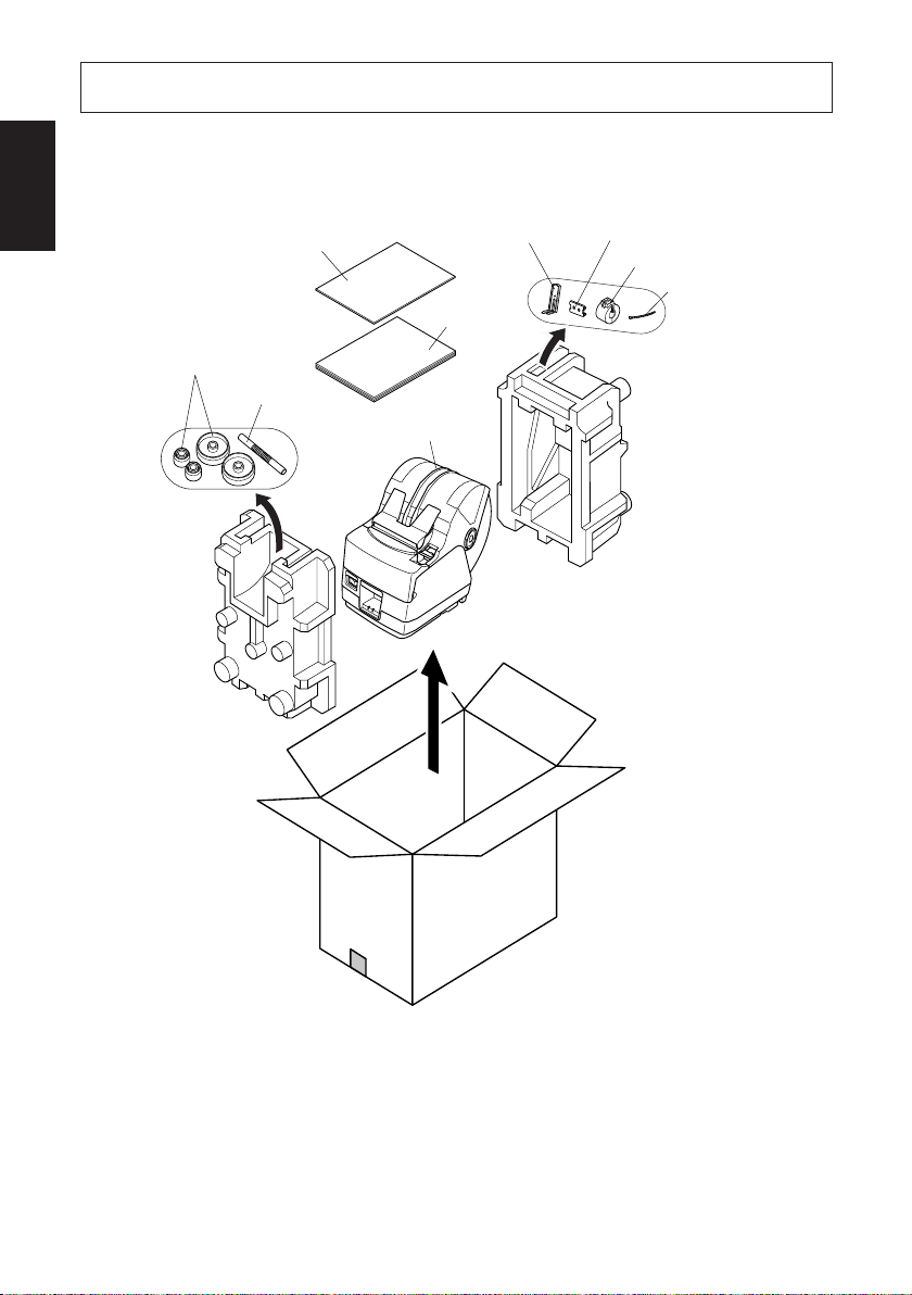
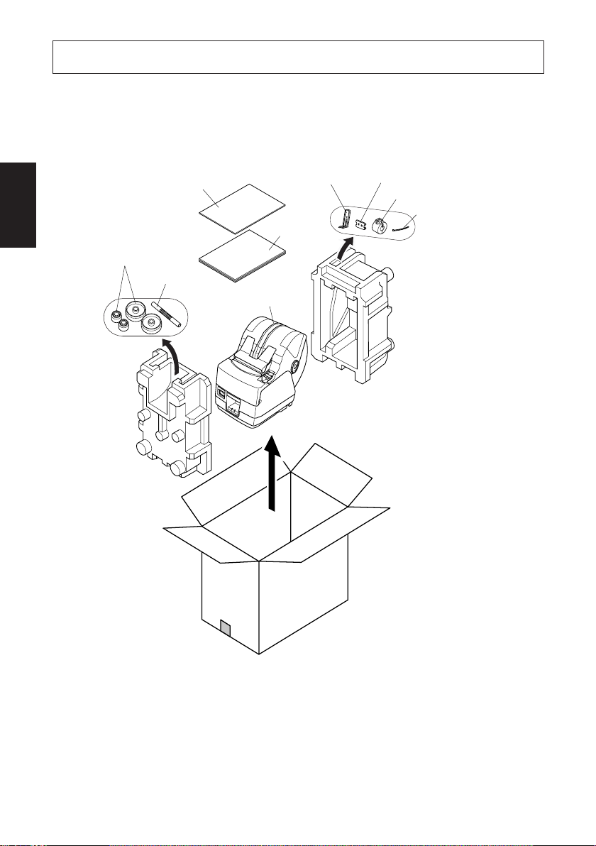
1. Unpacking and Installation
ENGLISH
1-1. Unpacking
After unpacking the unit, check that all the necessary accessories are included in
the package.
Roll paper
holders *3
Installation sheet
Roll paper
shaft *3
Paper stopper
User’s manual
Printer
Switch blind
Ferrite core *1
Fastener *2
*1: Not included with RS-232C model
*2: Not included with RS-232C and
USB models
*3: TSP1043 model only
Fig. 1-1 Unpacking
If anything is missing, contact the dealer where you bought the printer and ask
them to supply the missing part. Note that it is a good idea to keep the original box
and all the packing materials just in case you need to pack the printer up again and
send it somewhere at a later date.
– 1 –
Page 5
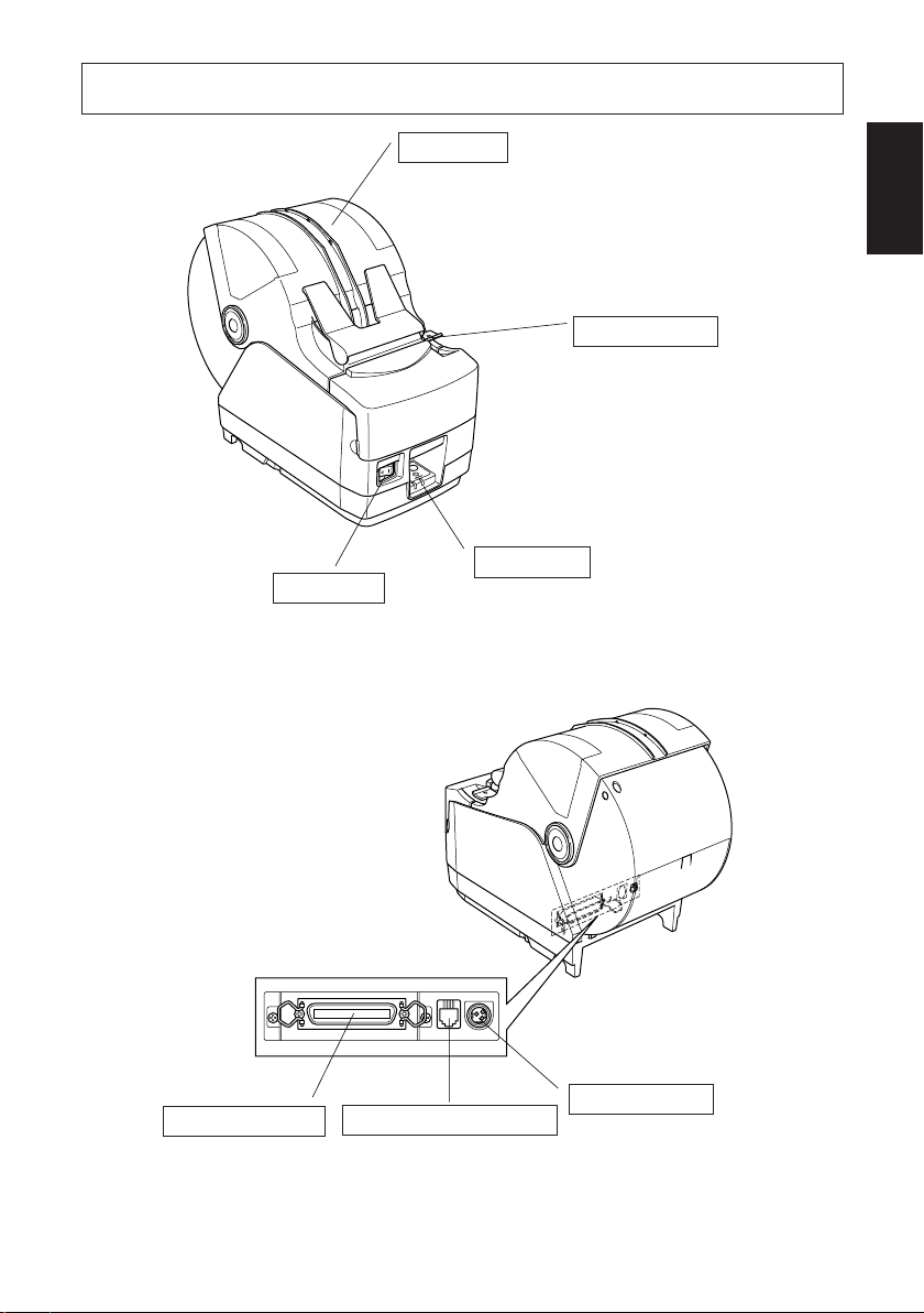
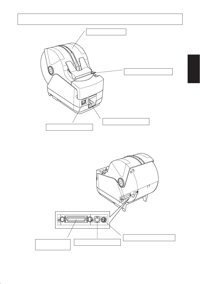
2. Parts Identification and Nomenclature
Printer cover
Open this cover to load or
replace paper.
ENGLISH
Cover open lever
Push this lever in
the direction of the
arrow to open the
printer cover.
Control panel
Power switch
Used to turn on/off
power to the printer.
Features LED indicators to indicate printer
status and switches to
operate the printer.
Interface connector
For connection to a
host computer.
Buzzer drive connector
Connects to buzzer.
Do not connect this to a
telephone.
– 2 –
Power connector
For connection of
the AC adapter.
Never unplug the
AC adapter while
the printer is on.
Page 6

Choosing a place for the printer
ENGLISH
Before actually unpacking the printer, you should take a few minutes to
think about where you plan to use it. Remember the following points
when doing this.
✓ Choose a firm, level surface where the printer will not be exposed to
vibration.
✓ The power outlet you plan to connect to for power should be nearby
and unobstructed.
✓ Make sure that the printer is close enough to your host computer for
you to connect the two.
✓ Make sure that the printer is not exposed to direct sunlight.
✓ Make sure that the printer is well away from heaters and other sources
of extreme heat.
✓ Make sure that the surrounding area is clean, dry, and free of dust.
✓ Make sure that the printer is connected to a reliable power outlet. It
should not be on the same electric circuit as copiers, refrigerators, or
other appliances that cause power spikes.
✓ Make sure that the room where you are using the printer is not too
humid.
WARNING
✓ Shut down your equipment immediately if it produces smoke, a
strange odor, or unusual noise. Immediately unplug the equipment
and contact your dealer for advice.
✓ Never attempt to repair this product yourself. Improper repair work
can be dangerous.
✓ Never disassemble or modify this product. Tampering with this
product may result in injury, fire, or electric shock.
– 3 –
Page 7

3. Consumable Parts and AC Adapter
When consumable parts have run out, use those specified in the table below.
Make sure that the AC adapter specified in the table is used.
Use of consumable parts or an AC adapter which are not specified in the table may
result in damage to the printer, fire or electric shock.
(1) Roll paper specifications
Thermal paper
µ
Thickness: 65 to 150
Width: 44.5±0.5 to 82.5±0.5 mm
Outer roll diameter: Max. ø180 mm
Take up paper roll width:45 to 83 mm
Core outer/inner diameter
Paper thickness Core outer Core inner
65 – 100 µm Max. ø40±1 mm Max. ø25.4±1 mm
100 – 150 µm Max. ø58±1 mm Max. ø50.8±1 mm
Printed surface: Outer surface of roll
Tail end handling: Do not use paste or glue to secure the roll paper or
m
(When using drop-in paper loading)
Max. ø170 mm
(When using roll paper shaft)
+0.5
-1
+0.5
-1
its core.
Do not fold the tail end of the paper.
ENGLISH
(2) Recommended paper
Mitsubishi Paper Mills Limited
T8037 (tickets), 85 µm (thickness)
TF8067 (tickets), 84 µm (thickness)
TF8075 (tickets), 85 µm (thickness)
KANZAN
KLS46 (tickets)
KPO460 (tickets)
Kanzaki Specialty Papers Inc. (KSP)
Lotto482 (tickets), 84 µm (thickness)
Depending on the type and thickness of the paper, it may be necessary to change
the settings for printing darkness. To change the darkness settings, use the
printing darkness settings command <ESC><RS> ‘d’ n or the memory switch
settings. Refer to the separate Specification Manual for details.
– 4 –
Page 8

(3) AC adapter (option)
Model name: PS60
ENGLISH
Input: 100 to 240 V AC, 50/60 Hz
Output: DC24±5%, 2.0 A (5.0 A Load 10 sec. Max.)
CAUTION
Access the following URL for the information of the recommended paper.
http://www.star-m.jp/eng/dl/dl02.htm
– 5 –
Page 9
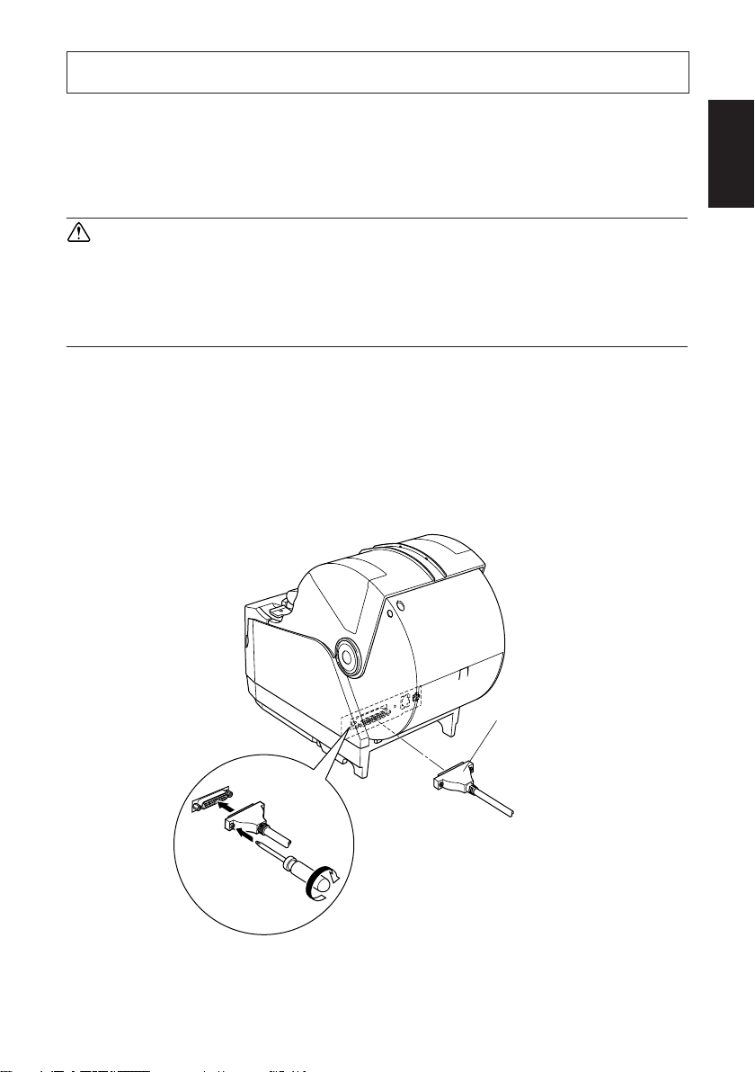
4. Connecting Cables and AC Adapter
4-1. Interface Cable
Note that the interface cable is not provided. Please use a cable that meets
specifications.
CAUTION
Before connecting/disconnecting the interface cable, make sure that
power to the printer and all the devices connected to the printer is turned
off. Also make sure the power cable plug is disconnected from the AC
outlet.
4-1-1. Serial Interface (RS-232C) Cable
(1)Make sure the printer is turn off.
(2)Connect the interface cable to the connector on the rear panel of the printer.
(3)Tighten the connector screws.
ENGLISH
– 6 –
Serial interface cable
Page 10

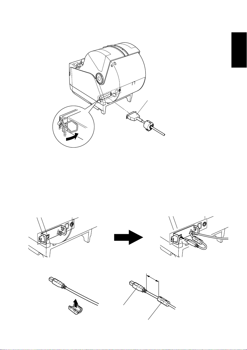
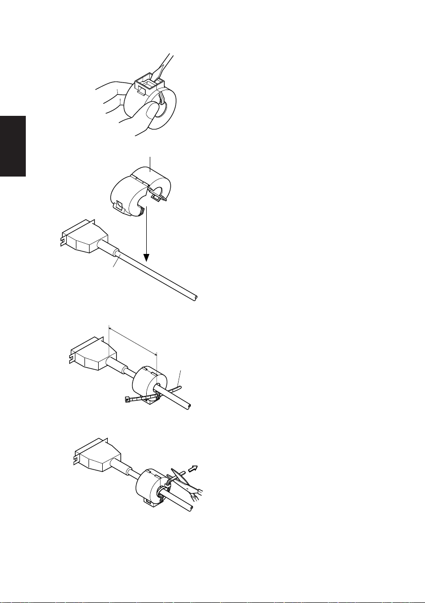
4-1-2. Parallel Interface Cable
ENGLISH
Interface cable
Ferrite core
5 cm
maximum
(1)Make sure the printer is turn off.
(2) For only the parallel interface model,
affix the ferrite core onto the cable
as shown in the illustration below.
(3)Pass the fastener through the ferrite
core.
Fastener
Pull and cut
(4)Loop the fastener around the cable
and lock it. Use scissors to cut off
any excess.
– 7 –
Page 11
(5)Connect the interface cable to the connector on the rear panel of the printer.
(6)Fasten the connector clasps.
Parallel interface cable
4-1-3. Connecting USB Cable
(1)Make sure the printer is turn off.
(2)Affix the ferrite core onto the USB cable as shown in the illustration below and
make sure to pass the cable through the cable support as shown in the
illustration.
ENGLISH
Plug
– 8 –
4cm (Maximum)
Ferrite core
Page 12

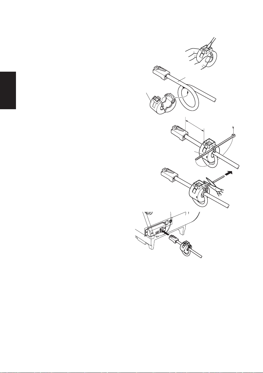
4-1-4. Connecting Ethernet Cable
ENGLISH
(1)Make sure the printer is turned off.
(2)Affix the ferrite core onto the
ethernet cable as shown in the illustration below.
Ethernet cable
Ferrite core
(3)Pass the fastener through the ferrite
core.
(4)Loop the fastener around the cable
and lock it. Use scissors to cut off
any excess.
(5)Connect the ethernet cable to the
connector on the interface board.
Then, connect the other end of the
cable to your computer.
10cm
(Maximum)
Fastener
– 9 –
Page 13
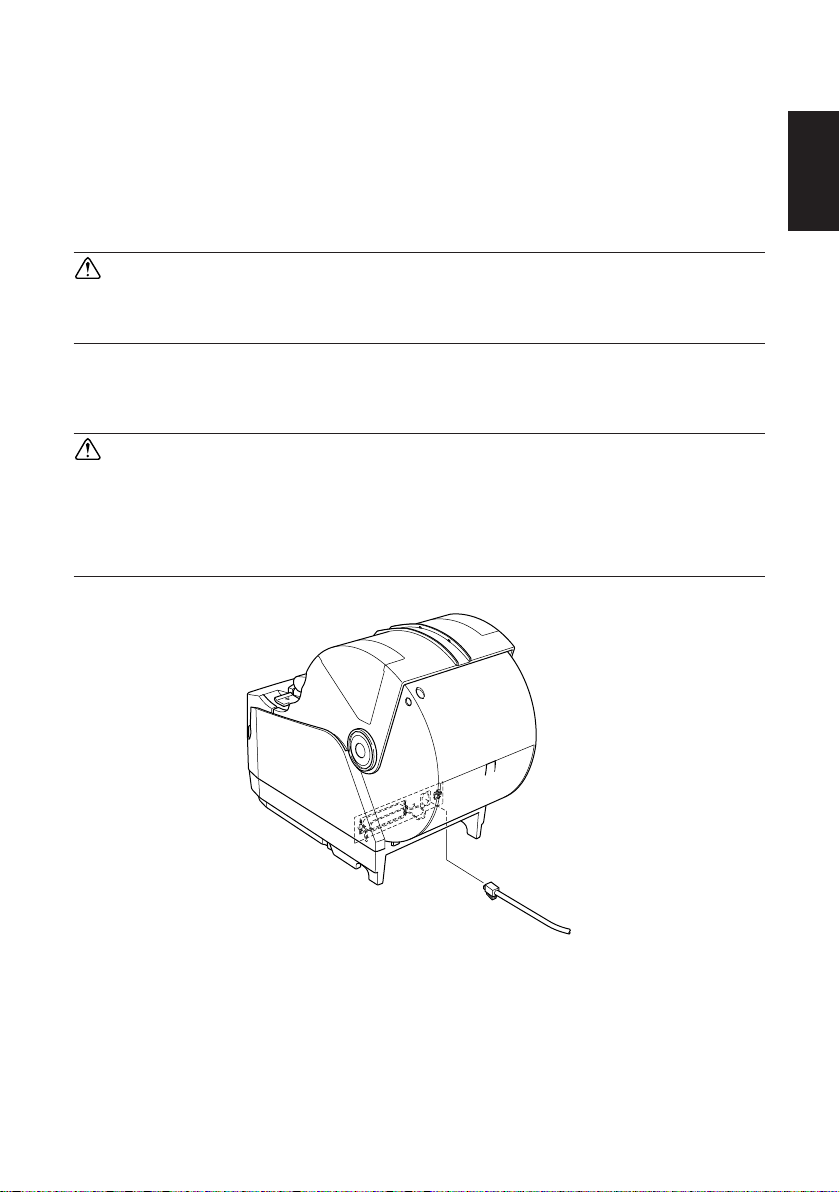
4-2. Connecting to a Buzzer Drive
You can connect a buzzer drive to the printer using a modular plug. The following
describes how to make the actual connection. See “Modular plug” on page 149
for details about the type of modular plug that is required. Note that this printer
does not come with a modular plug or wire, so it is up to you to obtain one that
suits your needs.
CAUTION
Make sure that the printer is turned off and unplugged from the AC outlet
and that the computer is turned off before making connections.
Connect the buzzer drive cable to the connector on the rear panel of the printer.
CAUTION
Do not connect a telephone line into the buzzer drive connector. Failure
to observe this may result in damage to the printer.
Also, for safety, do not connect wiring to the buzzer drive connector if
there is a chance it may carry excess voltage.
ENGLISH
– 10 –
Page 14
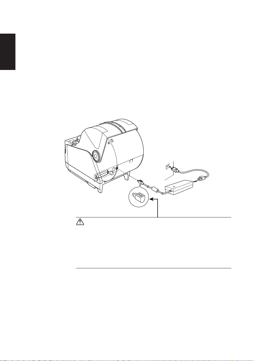
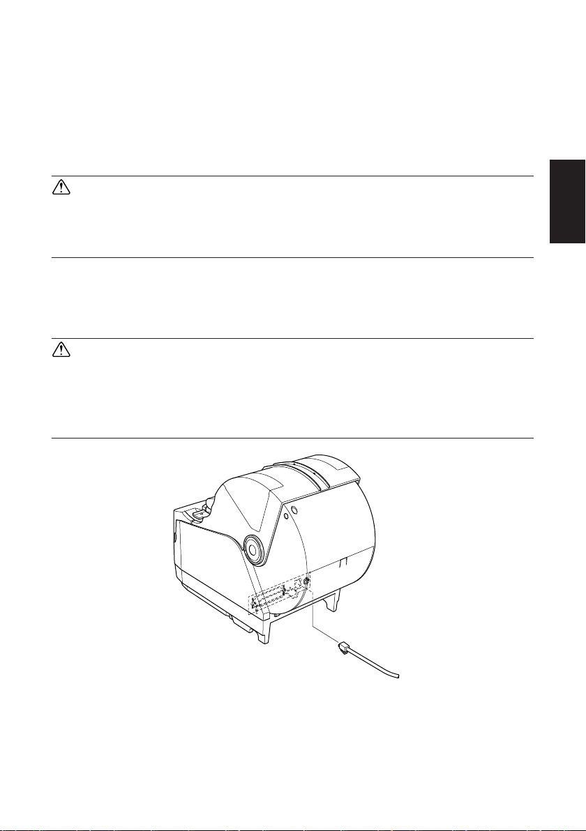
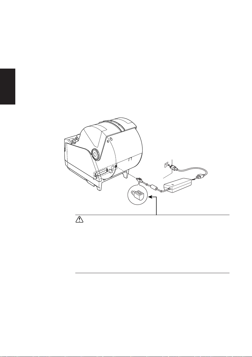
4-3. Connecting the Optional AC Adapter
ENGLISH
Note: Before connecting/disconnecting the AC adapter, make sure that
power to the printer and all the devices connected to the printer is
turned off. Also make sure the power cable plug is disconnected from
the AC outlet.
(1)Connect the AC adapter to the power cable.
Note: Use only the standard AC adapter and power cable.
(2)Connect AC adapter to the connector on the printer.
(3)Insert the power cable plug into an AC outlet.
CAUTION
When disconnecting the cable, take hold of the cable
connector to pull it out. Releasing the lock makes it
easy to disconnect the connector.
Pulling the cable excessively could cause damage to
the connector.
– 11 –
Page 15
4-4. Turning Power On
Make sure that the AC adapter has been connected as described in 4-3.
(1)Set the power switch located on the front of the printer to on.
The POWER lamp on the control panel will light up.
Power switch
CAUTION
We recommend that you unplug the printer from the power outlet
whenever you do not plan to use it for long periods. Because of this, you
should locate the printer so that the power outlet it is plugged into is
nearby and easy to access.
ENGLISH
– 12 –
Page 16
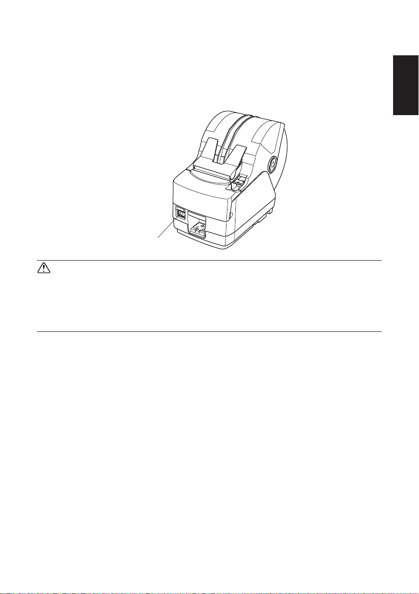
4-5. Installing the Cable
Install the cable as shown in the diagram below.
ENGLISH
– 13 –
Page 17
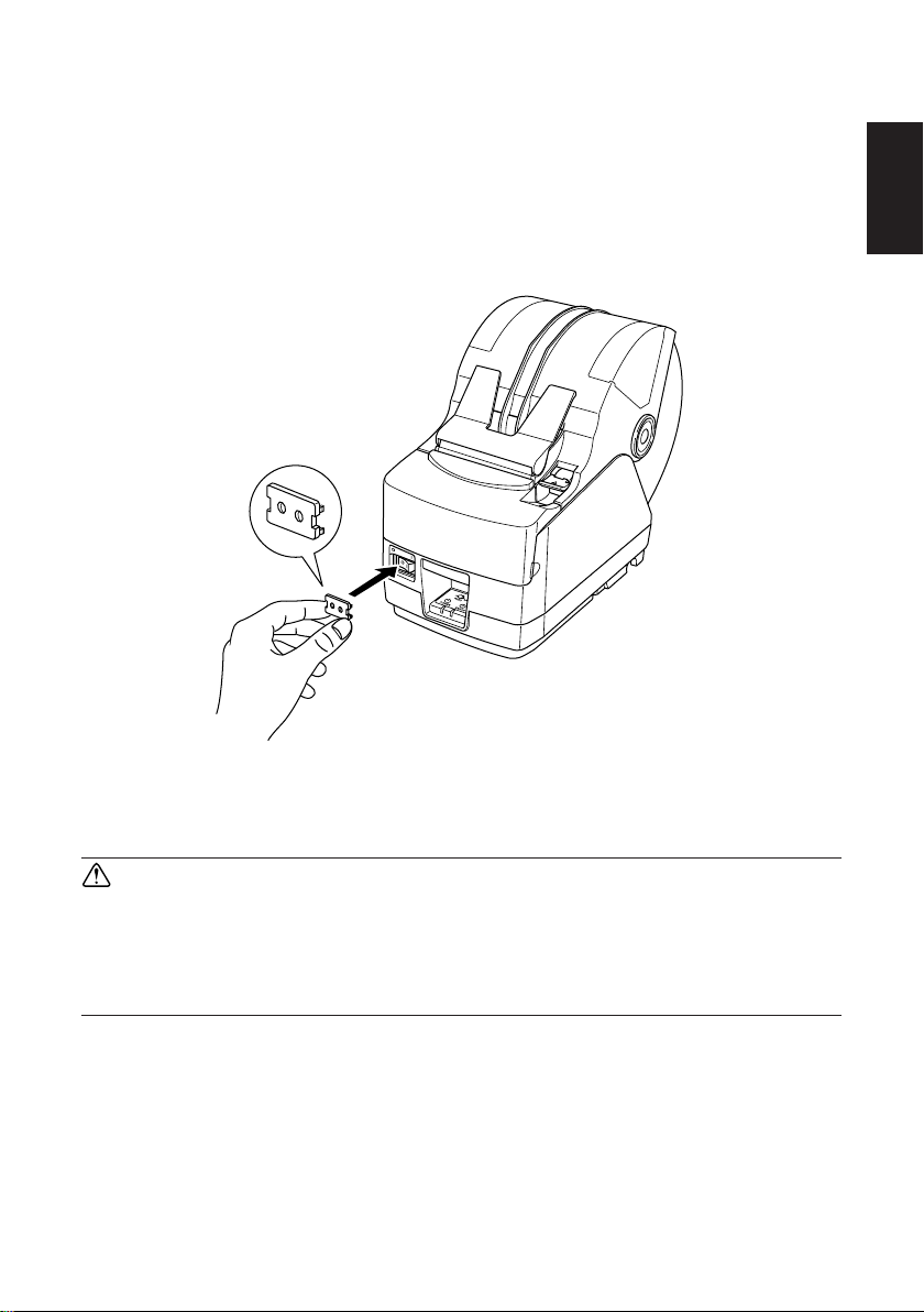
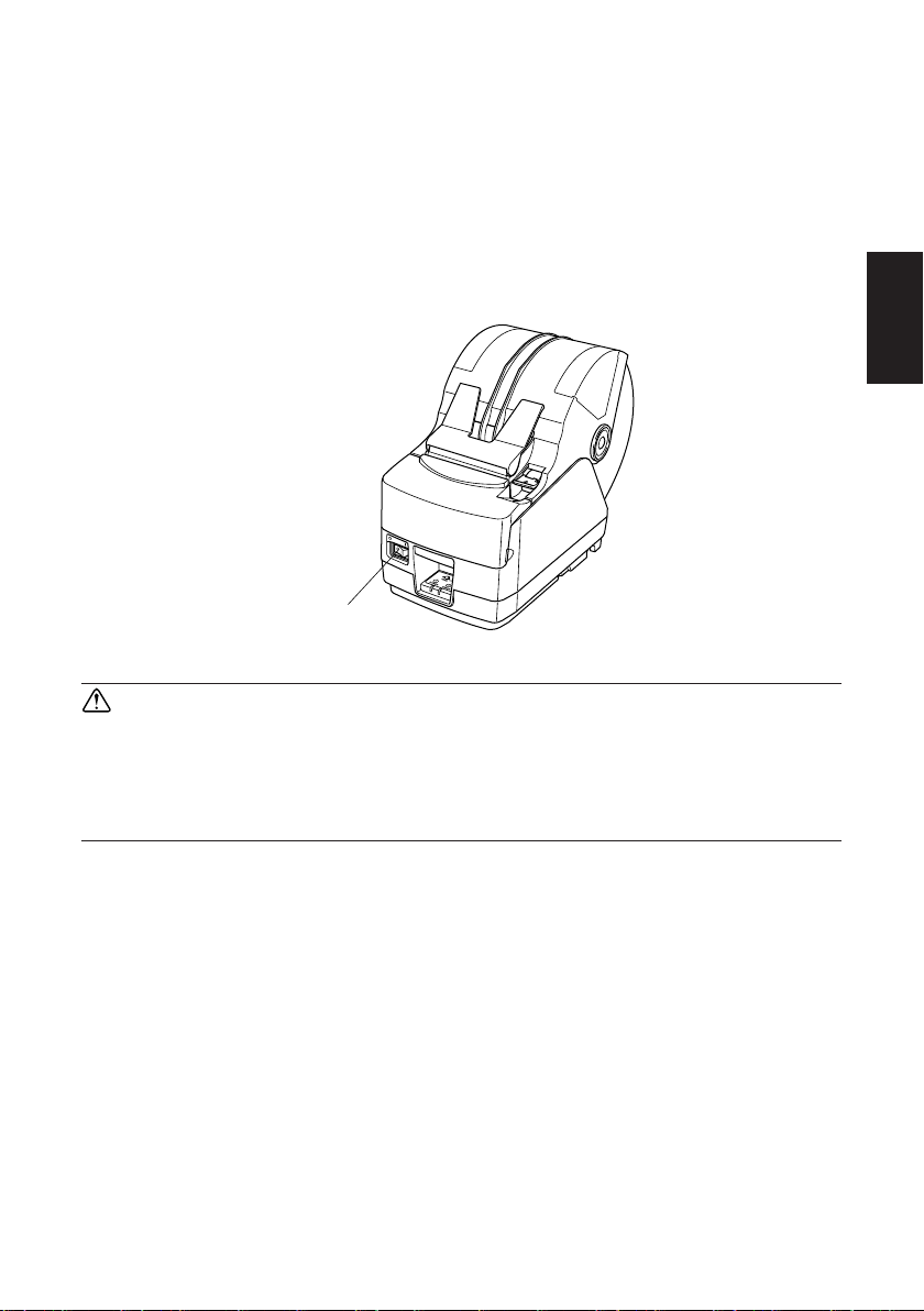
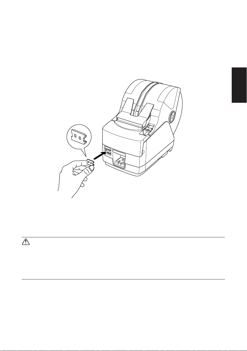
4-6. Switch Blind Installation
It is not necessary to install the switch blind. Only install it if it is necessary for
you. By installing the switch blind, the following become possible.
• Preventing the power switch from being operated by mistake.
• Ensuring that other people can not easily operate the power switch.
Install the switch blind as shown in the diagram below.
ENGLISH
The power switch can be turned ON (!) and OFF (O) by inserting a narrow
instrument (ball pen etc.) in the holes in the switch blind.
CAUTION
We recommend that you unplug the printer from the power outlet
whenever you do not plan to use it for long periods. Because of this, you
should locate the printer so that the power outlet it is plugged into is
nearby and easy to access.
– 14 –
Page 18
ENGLISH
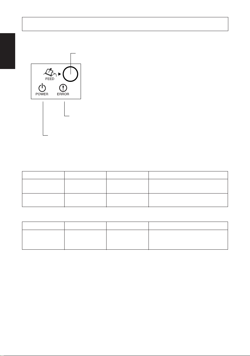
5-1. Control Panel
5. Control Panel and Other Functions
2 FEED button
1 POWER lamp (Green LED)
Lights when the power is ON
2 FEED button
Press the FEED button to feed roll
paper.
3 ERROR lamp (Red LED)
3 ERROR lamp
(Red LED)
1 POWER lamp (Green LED)
Indicates various errors in combination with POWER lamp
5-2. Errors
(1) Automatically recoverable error
Error Description
Head high tem-
perature detection
Cover open error
POWER lamp
Flashes at 0.5 sec-
ond intervals
On
(2) Recoverable error
Error Description
Paper cut error
POWER lamp
Off
Note:
1) If the cutter doesn’t return to the home position, or doesn’t perform the
initial movement, it cannot be recovered.
2) If the paper is jammed, turn the power off, clear the jammed paper, then
turn the power ON.
ERROR lamp
Off
On
ERROR lamp
Flashes at 0.125
second intervals
Recovery Conditions
Automatically recovered after the
print head has cooled.
Automatically recovered by closing
the printer cover.
Recovery Conditions
Recovered If the cutter returns to the
home position after turning the power
OFF and ON.
– 15 –
Page 19

(3) Non recoverable error
Error Description
RAM error
EERROM error
Flash ROM error
Thermistor error
Power supply
error
POWER lamp
Off
Off
Off
Off
Off
ERROR lamp
Flashes at 1.0
second intervals
Flashes at 0.75
second intervals
Flashes at 0.5
second intervals
Flashes at 1.5
second intervals
Flashes at 2
second intervals
Recovery Conditions
This is not a recoverable error.
Consult dealer for repairs.
This is not a recoverable error.
Consult dealer for repairs.
This is not a recoverable error.
Consult dealer for repairs.
This is not a recoverable error.
Consult dealer for repairs.
This is not a recoverable error.
Consult dealer for repairs.
Note:
1) If a non recoverable error occurs, turn the power OFF immediately.
2) When Power supply error occurs, there is a possibility that the power
supply unit has a trouble.
For other non recoverable errors, please consult the dealer for repairs.
(4) Paper detection error
Error Description
Paper out error
Paper near end
POWER lamp
On
On
ERROR lamp
Flashes at 0.5
second intervals
Flashes at 2
second intervals
Recovery Conditions
Automatically recovered by loading
a new paper roll, then closing the
printer cover.
Indicators show that the paper end
is approaching, but the printer
continues to print.
ENGLISH
– 16 –
Page 20
5-3. Self Printing
(1)Test Printing
ENGLISH
Turn the power on while holding the FEED button depressed.
Test printing will be performed according to the Ver. No., DIP switch settings
and memory switch settings.
(2) Hexadecimal Dump Mode
Open the printer cover, then turn the power on while holding the FEED button.
When the cover is closed, “*** HEX DUMP PRINTING ***” is printed, and
the printer enters the Hexadecimal Dump Mode.
Each of the signals sent from the computer to the printer will be printed out
in hexadecimal code.
This function allows you to check if a control code sent to the printer by the
program being used is correct or not. The final line is not printed if its data is
less than one full line. However, if the FEED button is pushed, the final line
is printed. To turn off the mode, it is necessary to turn off the printer
completely.
– 17 –
Page 21
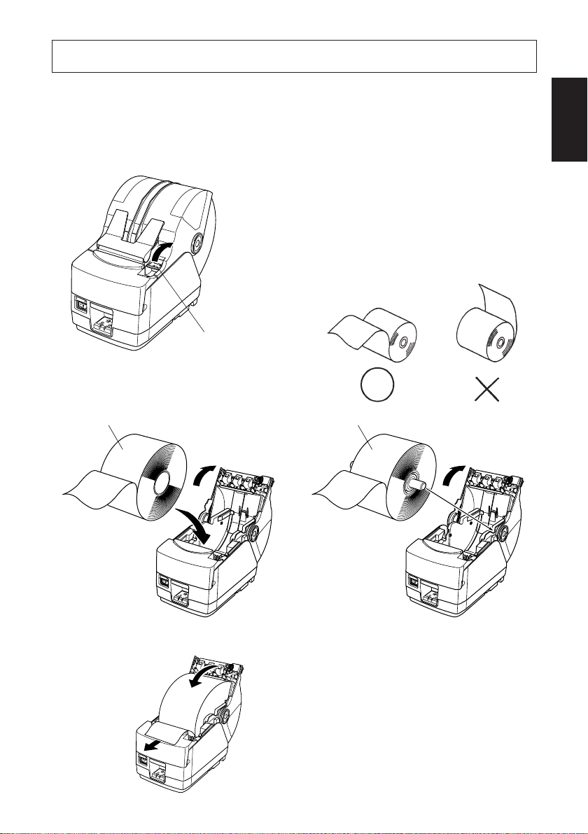
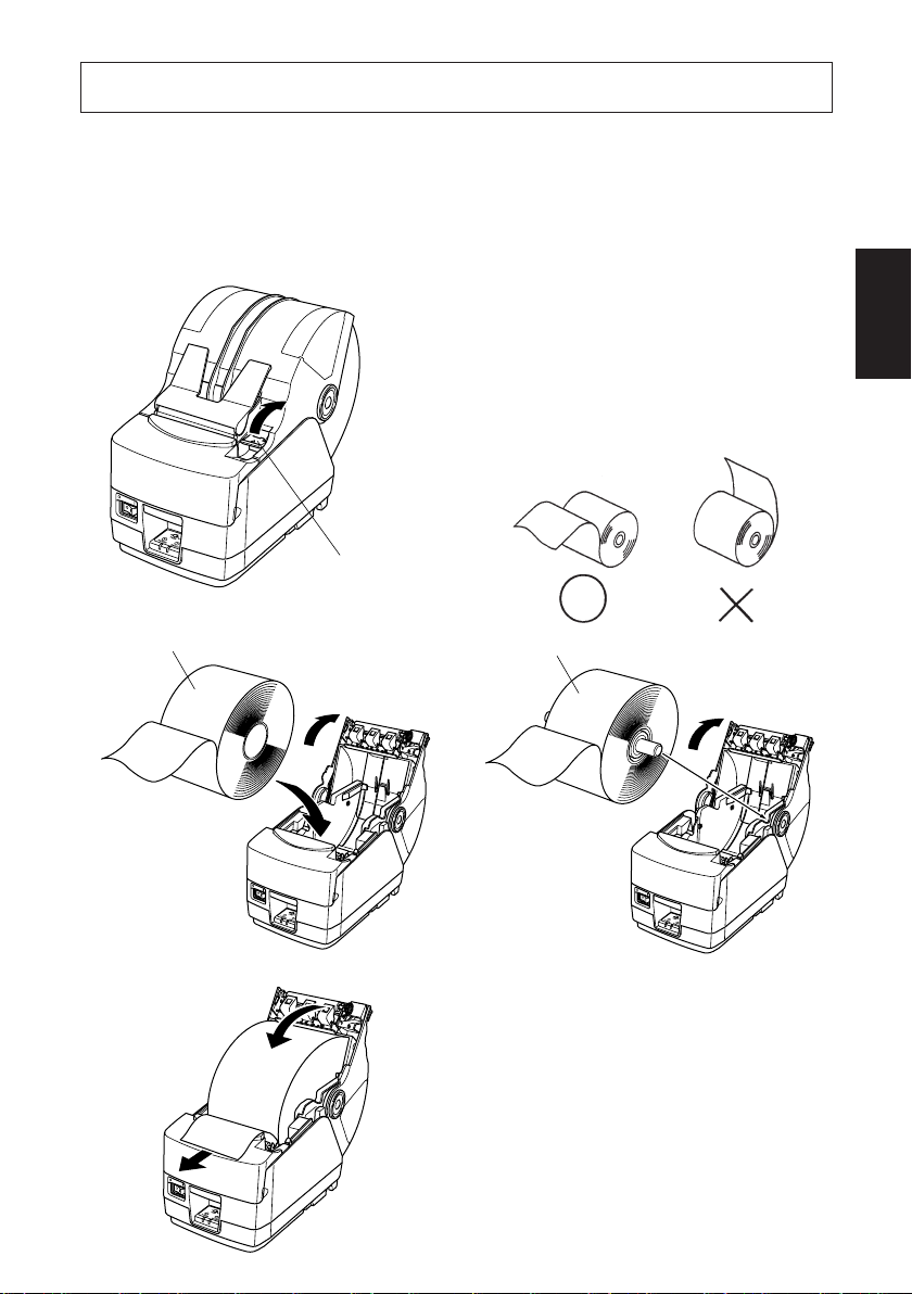
6. Loading the Roll Paper
6-1. Loading the Roll Paper
Loading the roll paper in this printer differs according to the type of paper (dropin roll paper or roll paper that requires the shaft). Load the roll paper according
to the procedures on the section 6-2.
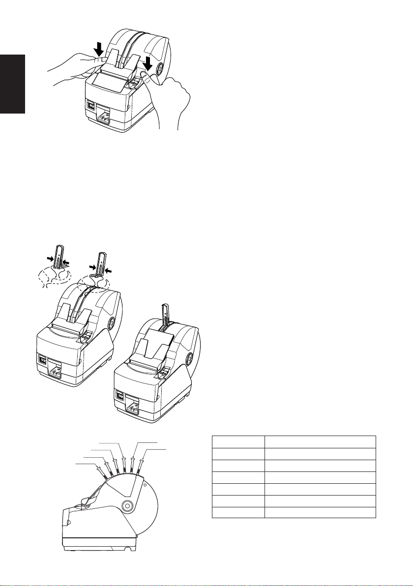
(1) Push the Cover open lever, and open
the printer cover.
(2) While observing the direction of the
roll, set the roll paper into the hollow, and pull the leading edge of the
paper toward you.
Cover
open lever
ENGLISH
Roll paper
Roll paper
[Drop-in paper loading] [Using shaft]
– 18 –
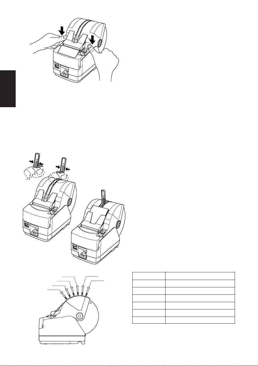
Page 22
ENGLISH
(3)Pull on the edge of the paper to
remove any slack and then push
down both sides of the printer cover
to close it.
Note: Make sure that the printer
cover is securely closed.
(4)If the printer cover is closed after
turning on the power, the cutter operates automatically and the front
end of the paper is cut.
Note: If the cutter does not operate
after the printer cover is
closed, open the cover and
close it again securely.
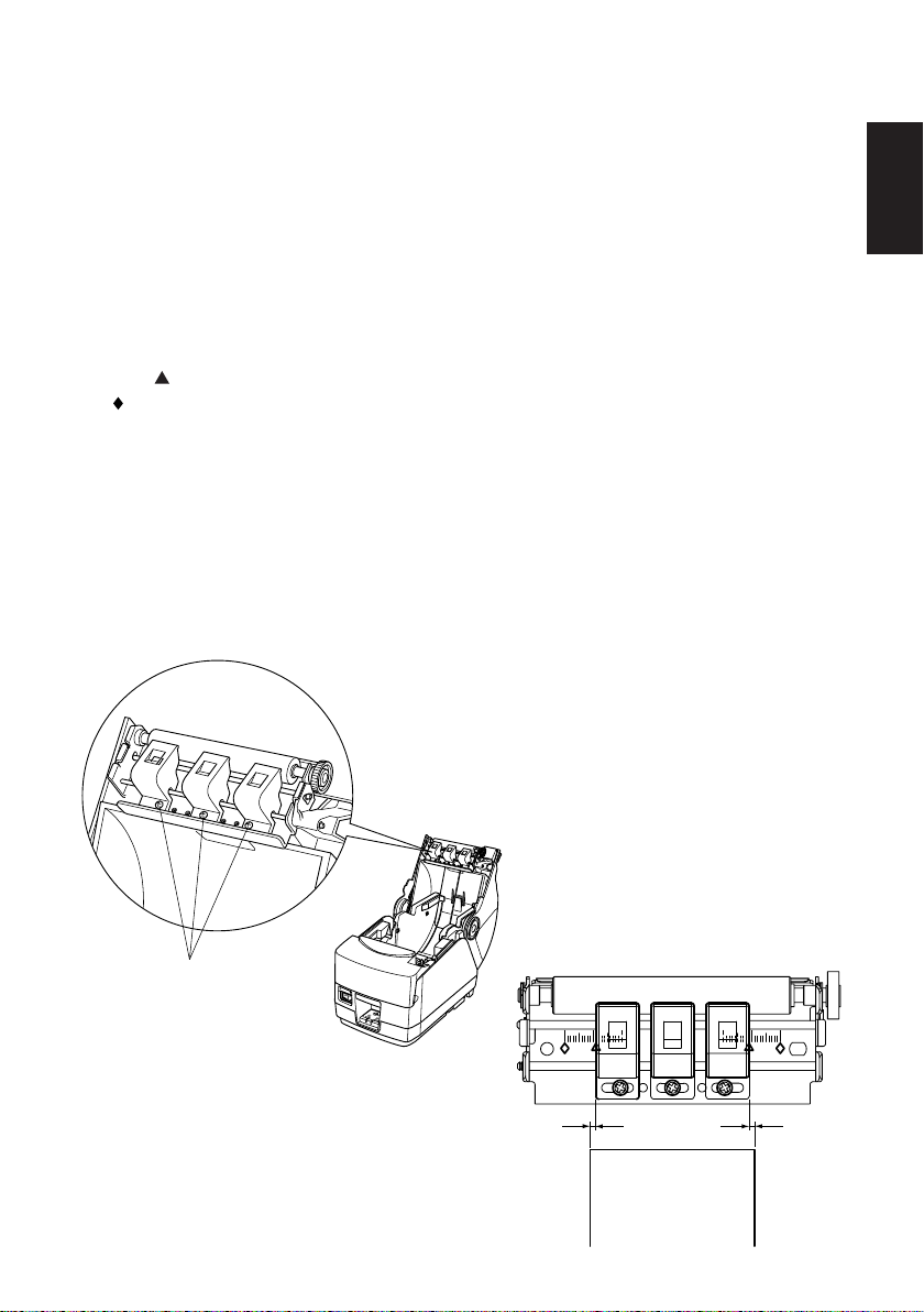
(5)If necessary, attach the paper stop-
per to the paper cover as shown. The
output tray can hold up to 30 sheets
(width:80-82.5 mm, thickness: 80–
µ
m, length: 50–150 mm). For
120
paper with a different thickness or
for other sheet lengths, the limit is
10 sheets.
Note: When attaching the paper
stopper to the paper cover,
position the stopper according to the length of the cut
paper. (Refer to the following table.)
Position 1
Position 2
Position 3
Position 4
Position 5
Position 6
Paper length (mm)
Position 1 50 – 100
Position 2 100 – 120
Position 3 120 – 140
Position 4 140 – 160
Position 5 160 – 180
Position 6 180 – 200
– 19 –
Page 23

WARNING
• Do not touch the cutter blade.
- There is a cutter inside the paper outlet slot. Not only should you not
put your hand in the paper outlet slot while printing is in progress,
never put your hand into the outlet even when printing is not in
progress.
- The printer cover can be opened when replacing the paper. However, since the cutter blade is on the inside of the printer cover, be
careful not to place your face or hands too close to the cutter blade.
• During and immediately after printing, the area around the thermal
head is very hot. Do not touch it, as you could be burned.
CAUTION
• Do not operate the cover open lever while pressing on the printer
cover with your hand.
• Do not pull out paper while the printer cover is closed.
• The heating element and the driver IC of the thermal head are easily
damaged. Do not touch them with metal objects, sandpaper, etc.
• Printing quality may suffer if the thermal head heating element
becomes soiled by being touched with your hands. Do not touch the
thermal head heating element.
• There is a risk of damage to the driver IC of the thermal head from
static electricity. Never directly touch the IC.
• The printing quality and working life of the thermal head cannot be
guaranteed if any paper other than that recommended is used. In
particular, paper containing [Na+, K+, C1-] may drastically reduce
the working life of the thermal head. Please exercise caution.
• Do not operate the printer if there is moisture on the front surface of
the head from condensation, etc.
ENGLISH
– 20 –
Page 24

6-2. Paper Loading Methods
This printer has two paper loading methods: one when using the roll paper shaft,
ENGLISH
and one when not using the shaft. The roll paper shaft is not used for drop-in paper
loading. Select the paper loading method from the following table according to
the type of paper used.
Paper width (mm)
Paper thickness (µm)
65 Thickness < 80 Use roll paper shaft (*1, *4) Use roll paper shaft (*2)
80 Thickness 120 Use roll paper shaft (*1, *4) Use drop-in loading (*3)
120 < Thickness
150 Use roll paper shaft (*1) Use roll paper shaft (*1)
Note:
*1: Maximum outer roll diameter: 150 mm
*2: Maximum outer roll diameter: 170 mm
*3: Maximum outer roll diameter: 180 mm
*4: The print speed must be changed from the high speed (factory default
setting) to the middle speed (140 mm/sec.). To change the print speed, use
the print speed settings command <ESC><RS> Rn. Refer to the separate
Specification Manual for details.
44.5 Width < 79.5 79.5 Width 82.5
– 21 –
Page 25

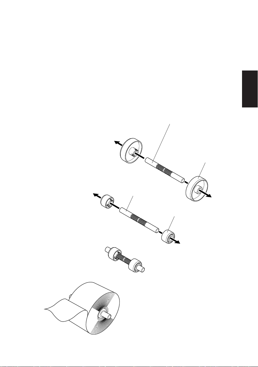
6-3. Roll Paper Holder Adjustment
There are two different sized roll paper holders: roll paper holders 1 for paper that
has a one-inch inner core diameter, and roll paper holders 2 for paper that has a
two-inch inner core diameter. Select the roll paper holders according to the size
of roll paper used.
(1)Install the roll paper holders onto both ends of the roll paper shaft.
(2) Adjust the positions of the roll paper holders according to the width of the roll
paper used.
(3)Insert the roll paper holders and shaft into the roll paper.
Roll paper shaft
Roll paper holder 2
Roll paper shaft
ENGLISH
– 22 –
Roll paper holder 1
Page 26

6-4. Paper Guide Adjustment
When the printer is shipped from the factory, the paper guides and upper guides
ENGLISH
are adjusted for roll paper with the following width.
Paper width: 79.5 ± 0.5 mm (TSP1043)
Paper width: 82.5 ± 0.5 mm (TSP1045)
When using roll paper with a width other than listed above, perform the following
procedure to adjust the paper guides. To adjust the upper guides, refer to “6-5
Upper Guide Adjustment”.
(1)Loosen the four screws.
(2)Adjust the left and right paper guides according to the width of the roll paper,
making sure to leave approximately 0.5 mm of space between each guide and
the edge of the paper.
The scales on the metal plate inside the printer are divided into 1 mm segments
between the
wide paper and the two
ingly, for roll paper with a width of 79.5 mm, position each paper guide 0.5
mm to the outside of the respective
be removed and installed in the adjacent screw holes.
(3)Tighten the four screws.
marks. The two marks above the scales are used for 57.5 mm
marks are used for 79.5 mm wide paper. Accord-
mark. If necessary, screws 2 and 3 can
Screw 1
Left paper guide
Screw 3
Right paper guide
Screw 2
Screw 4
– 23 –
Page 27
6-5. Upper Guide Adjustment
When the printer is shipped from the factory, the upper guides are adjusted for roll
paper with a 79.5–82.5 mm width. When using roll paper with a different width,
perform the following procedure to adjust the upper guides.
(1)Loosen the two screws for the left and right upper guides.
(2)Adjust the left and right upper guides according to the width of the roll paper,
making sure that each guide is approximately 2 mm to the inside of the edge
of the paper.
The scales on the metal plate on the cover are divided into 1 mm segments. The
marks below the scales are used for 57.5 mm wide paper and the two
two
marks are used for 79.5 mm wide paper (also used for 82.5 mm wide paper).
If necessary, the screws for the left and right upper guides can be removed and
installed in the adjacent screw holes. If the roll paper width is 50 mm or less,
remove the center upper guide by removing its screw, and then adjust the left
and right upper guides.
Note:
When adjusting the upper guides, be careful not to pinch or apply unnecessary
force to the wires.
(3)Tighten the two screws.
ENGLISH
Screws
– 24 –
2mm
2mm
Page 28
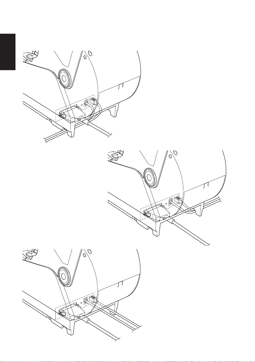
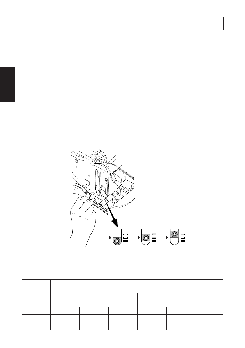
7. Adjusting the Near-end Sensor
ENGLISH
Use the following procedure to adjust the near-end sensor so it is compatible with
the size of roll paper you are using.
1 Open the printer cover.
2 Determine the correct position of the adjuster from the following three
positions according to the paper loading method and the inner core diameter
of the roll paper.
Position 1: Using drop-in paper loading
Position 2: Using roll paper holder 2 (ø50.8 mm inner core)
Position 3: Using roll paper holder 1 (ø25.4 mm inner core)
3 Insert the tip of a ballpoint pen or similar object into the hole of the adjuster,
and then push and slide the adjuster to the desired position.
Position 3
Position 2
Position 1
(Level 1) (Level 2)
(Level 3)
The amounts of remaining paper that can be detected are shown in the following
table.
(1)Position 1
When using roll paper with an inside core diameter (A): ø25.4 and outside core
µ
m)
diameter (B): ø40
Detected diameter (C)
(Approx. mm)
Level 1 Level 2 Level 3 Level 1 Level 2 Level 3
ø44 ø48 ø52
– 25 –
Remaining paper length
(Approx. m)
3.5 7.5 12.5
1.5 4.5 7.5
Paper thick-
ness (
80
105
Page 29
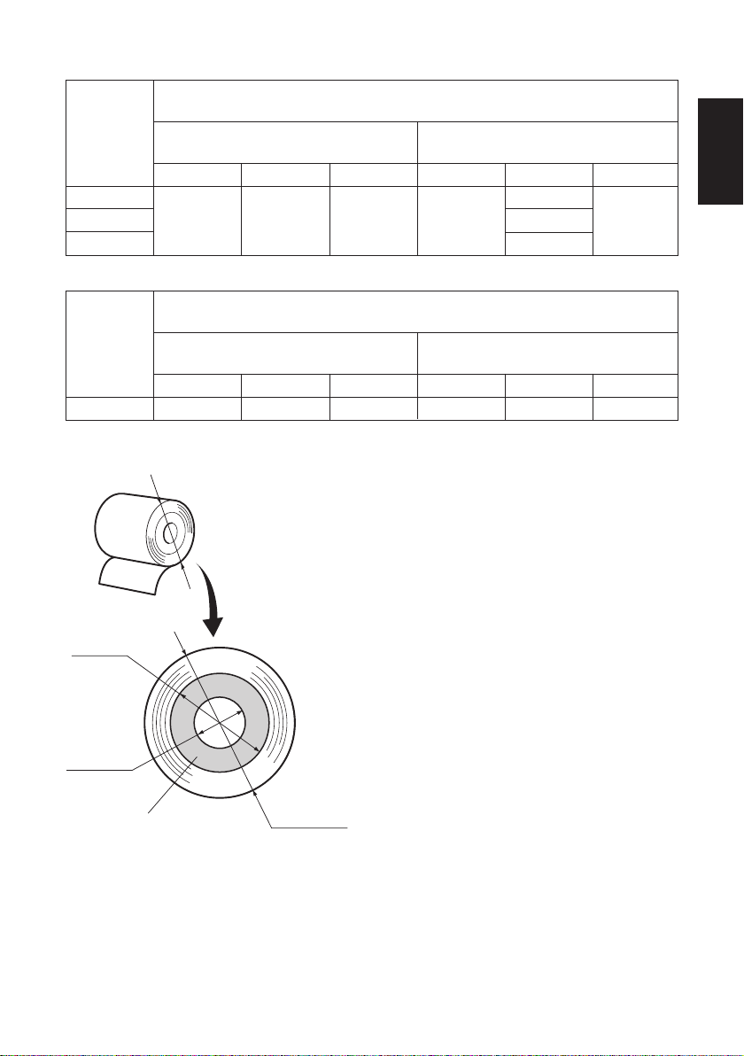
(2)Position 2
Paper thick-
ness (
µ
m)
65
80
105
(3)Position 3
Paper thick-
µ
m)
ness (
150
When using roll paper with an inside core diameter (A): ø25.4 and outside core
diameter (B): ø40
Detected diameter (C)
(Approx. mm)
Level 1 Level 2 Level 3 Level 1 Level 2 Level 3
—ø45 ——4.4 —
When using roll paper with an inside core diameter (A): ø 50.8 and outside core
diameter (B): ø58
Detected diameter (C)
(Approx. mm)
Level 1 Level 2 Level 3 Level 1 Level 2 Level 3
—ø69 ——6.5 —
Remaining paper length
(Approx. m)
5.6
3.2
Remaining paper length
(Approx. m)
ENGLISH
C
B
A
Roll paper core
Note:
1) The adjuster is set to position 1,
level 2 prior to being shipped from
the factory.
2) The C dimension and the remained
paper length are the calculated values. There may be some variations
in actual mechanism.
3) The remaining paper lengths shown
in the table above are for reference
only. Adjust the near-end sensor to
suit the actual conditions of use.
4) If thick paper is used (100 µm or
greater paper thickness) when the
C
adjuster is set to position 1, there
will be looseness in the roll paper
itself which makes it easier for detection variations to occur. Set to
Level 3.
– 26 –
Page 30

8. Preventing and Clearing Paper Jams
ENGLISH
8-1. Preventing Paper Jams
The paper should not be touched during ejection and before it is cut.
Pressing or pulling the paper during ejection may cause a paper jam, paper cutting
failure or line feed failure.
8-2. Removing Paper Jam
If a paper jam occurs, clear it as described below.
(1)Set the power switch to off to turn off power to the printer.
(2)Push the cover open lever, and open the printer cover.
If the printer cover will not open on auto cutter models, it means that the auto
cutter is not at the home position. In this case, return the auto cutter to the home
position by following the instructions provided in section 8-3. Then open the
printer cover after the paper jam has been removed.
(3)Remove the jammed paper.
CAUTION
Take care not to damage the printer when removing the jammed paper.
Since it is easy to damage the thermal head in particular, take care not
to touch it.
(4)Position the roll paper straight and close the printer cover gently.
Note:
1) Make sure that the paper is positioned straight. If the printer cover is closed
with the paper skewed, a paper jam may result.
2) Lock the printer cover by pressing down both sides. Make sure that the
printer cover is securely closed.
(5)Set the power switch to on to turn on power to the printer. Make sure that the
ERROR LED is not lit.
Note: While the ERROR LED is lit, the printer will not accept any commands
such as the print command, so make sure that the printer cover is locked
properly.
– 27 –
Page 31

8-3. Releasing a Locked Cutter
If the auto cutter locks up or fails to cut the paper, follow the steps below.
WARNING
Since working on the cutter may be dangerous, be sure to turn off the printer first.
(1)Set the power switch to OFF to turn off the printer.
(2)Slide off the front cover to reveal the auto cutter.
(3)Remove any jammed paper.
CAUTION
Be careful not to damage the printer while removing any jammed paper.
Since the thermal print head is particularly sensitive, be sure not to touch
it.
Front cover
ENGLISH
– 28 –
Page 32

(4)If the cutter’s moving blade is protruding, rotate the knob in the direction of
an arrow to return the moving blade to its home position.
ENGLISH
When the check window is completely white, the moving blade is at its home
position.
CAUTION
1) Do not apply extreme pressure to the moving blade.
2) If the moving blade is protruding too much, the printer cover cannot
be opened. Trying to open the printer cover may damage the cutter.
(5)Open the printer cover, remove any jammed paper, and then re-install the
paper roll.
(6)Install the front cover, and then set the power switch to ON.
– 29 –
Page 33

9. Periodical Cleaning
Printed characters may become partially unclear due to accumulated paper dust
and dirt. To prevent such a problem, paper dust collected in the paper holder and
paper transport section and on the surface of the thermal head must be removed
periodically. Such cleaning is recommended to be carried out once six month or
one million lines.
9-1. Cleaning the Thermal Head
To remove blackish dust collected on the surface of the thermal head, wipe it with
Isopropyl alcohol (IPA).
Note: The thermal head is easy to damage, so clean it gently with a soft cloth.
Take sufficient care not to scratch it when cleaning it.
9-2. Cleaning the Paper Holder
Use a soft cloth to remove paper dust from the paper holder and paper transport
section.
ENGLISH
– 30 –
Page 34

ENGLISH
– 31 –
Page 35

TABLE DES MATIERES
1. Déballage et inspection ..................................................................................33
1-1. Déballage .............................................................................................33
2. Identification des pièces et nomenclature....................................................34
3. Consommables et adaptateur secteur ..........................................................36
4. Câbles de connexion et adaptateur secteur .................................................38
4-1. Câble d’interface ..................................................................................38
4-2. Raccordement d’une sonnerie .............................................................. 42
4-3. Connexion de l’adaptateur secteur optionnel .......................................43
4-4. Mise sous tension de l’imprimante ...................................................... 44
4-5. Installation du câble .............................................................................45
4-6. Installation du cache de l’interrupteur .................................................46
5. Panneau de commande et autres fonctions .................................................47
5-1. Panneau de commande .........................................................................47
5-2. Erreurs .................................................................................................. 47
5-3. Auto-impression ...................................................................................49
6. Chargement du rouleau de papier ...............................................................50
6-1. Chargement du rouleau de papier ........................................................ 50
6-2. Méthodes de chargement du papier .....................................................53
6-3. Réglage du support de rouleau de papier .............................................54
6-4. Réglage des guides papier ....................................................................55
6-5. Réglage des guides supérieurs ............................................................. 56
7. Réglage du capteur de fin de rouleau ..........................................................57
8. Prévention et correction de bourrages de papier ....................................... 59
8-1. Prévention des bourrages de papier .....................................................59
8-2. Correction de bourrages de papier .......................................................59
8-3. Libération d’une unité de découpage bloquée ..................................... 60
9. Nettoyage ........................................................................................................62
9-1. Nettoyage de la tête d’impression ........................................................ 62
9-2. Nettoyage du support de papier ...........................................................62
APPENDICE ....................................................................................................128
FRANÇAIS
L’appendice n’est pas traduit.
Pour obtenir la dernière version de ce manuel, consultez l’adresse URL suivante:
http://www.star-m.jp/eng/dl/dl02.htm
– 32 –
Page 36
1. Déballage et inspection
1-1. Déballage
Après avoir déballé l’appareil, vérifiez si tous les accessoires nécessaires se
trouvent dans la boîte.
FRANÇAIS
Supports de
rouleau de
papier *3
Feuille
d’installation
Axe de
rouleau de
papier *3
Butée du papier
Mode
d’emploi
Imprimante
Cache de l’interrupteur
Tore de ferrite *1
Attache *2
*1: Non livré avec le modèle RS-232C
*2: Non livré avec les modèles RS-232C
et USB
*3: Uniquement sur le modèle TSP1043
Fig. 1-1 Déballage
Si l’un des éléments mentionnés ci-dessus ne se trouve pas dans la caisse,
adressez-vous au magasin où vous avez acheté l’imprimante et demandez que la
pièce manquante vous soit fournie. Il est préférable de conserver la caisse
d’origine ainsi que tous les emballages. Ceux-ci vous seront utiles s’il vous faut
emballer l’imprimante ou la transporter.
– 33 –– 33 –
Page 37
2. Identification des pièces et nomenclature
Capot de l’imprimante
Ouvrez ce capot pour
charger ou remplacer le
papier.
Levier d’ouverture du capot
Poussez ce levier dans le sens
de la flèche pour ouvrir le capot de l’imprimante.
Panneau des commandes
Interrupteur d’alimentation
Permet la mise sous et hors
tension de l’appareil.
Le panneau est équipé de
commutateurs permettant la
commande de l’imprimante
et de DELs indiquant les statuts.
FRANÇAIS
Connecteur
d’interface
Ce connecteur vous
permet de connecter
l’imprimante à l’ordi-
nateur-hôte.
Connecteur de sonnerie
Ce connecteur vous permet
de raccorder l’imprimante à
une sonnerie.
Ne pas raccorder à un télé-
phone.
– 34 –
Connecteur d’alimentation
Ce connecteur vous permet de
connecter le câble de l’adapta-
teur secteur. Ne déconnectez
pas le câble lorsque l’imprimante
est sous tension.
Page 38

Emplacement de l’imprimante
Avant de déballer l’imprimante, déterminez l’emplacement où vous
souhaitez l’installer. Veuillez observer les points ci-dessous lors de votre
choix.
✓ Choisissez une surface stable et de niveau sur laquelle l’imprimante
FRANÇAIS
ne sera exposée à aucune vibration.
✓ Assurez-vous que l’emplacement dispose d’une prise secteur proche
et d’accès aisé.
✓ Assurez-vous que la distance entre l’imprimante et l’ordinateur-hôte
vous permet de les raccorder aisément.
✓ Assurez-vous que l’imprimante n’est pas exposée directement aux
rayons du soleil.
✓ Tenez l’imprimante à l ’écart des sources de chaleur importante, telles
que les appareils de chauffage, etc.
✓ Assurez-vous que le lieu où vous souhaitez installer l'imprimante est
propre, sec et n'est pas poussiéreux.
✓ Assurez-vous que la prise secteur à laquelle vous raccordez l’impri-
mante délivre une tension stable. Evitez de raccorder l’imprimante à
la prise secteur d’un circuit alimentant de gros consommateurs de
courant, tels qu’un photocopieur, réfrigérateur, etc.
✓ Assurez-vous que le lieu où vous installez l’imprimante n’est pas
excessivement humide.
AVERTISSEMENT
✓ Éteignez immédiatement l’appareil en cas de dégagement de fumée
ou d’odeur anormale ou en cas de bruit inhabituel. Débranchez
immédiatement l’appareil et demander conseil à votre revendeur.
✓ Ne tentez jamais de réparer l’appareil vous-même. Une réparation
mal effectuée pose un risque de danger.
✓ Ne démontez ou ne modifiez jamais l’appareil. Une altération de
l’appareil risque de se traduire par des blessures, un incendie ou un
choc électrique.
– 35 –– 35 –
Page 39

3. Consommables et adaptateur secteur
Il convient d’utiliser exclusivement les types de papier figurant dans le tableau cidessous. Veillez également à utiliser l’adaptateur secteur qui figure dans le tableau.
L’utilisation d’un type de papier et d’adaptateur ne figurant pas dans le tableau risque
d’endommager l’imprimante, de causer un incendie ou une décharge électrique.
(1) Rouleau de papier, caractéristiques
Papier thermique
µ
Épaisseur: 65 à 150
Largeur: 44,5±0,5 à 82,5±0,5 mm
Diamètre extérieur du rouleau
: Max. ø180 mm
(Lors de l’utilisation du chargement du papier par simple
dépôt du rouleau dans l’imprimante)
: Max. ø170 mm
(Lors de l’utilisation de l’axe de rouleau de papier)
Largeur du rouleau de papier: 45 à 83 mm
Diamètre extérieur/intérieur du support de rouleau
Epaisseur du papier
65 – 100 µm Max. ø40±1 mm Max. ø25,4±1 mm
100 – 150 µm Max. ø58±1 mm Max. ø50,8±1 mm
Surface imprimée: Bord extérieur du rouleau
Extrémité arrière: Ne pas utiliser de colle pour immobiliser le rouleau
m
+0,5
+0,5
-1
-1
Extérieur du support de rouleau Intérieur du support de rouleau
de papier ou son noyau.
Ne pas plier l’extrémité arrière du papier.
FRANÇAIS
(2) Papier conseillé
Mitsubishi paper mills limited
T8037 (tickets), 85 µm (épaisseur)
TF8067 (tickets), 84 µm (épaisseur)
TF8075 (tickets), 85 µm (épaisseur)
KANZAN
KLS46 (tickets)
KPO460 (tickets)
Kanzaki Specialty Papers Inc. (KSP)
Lotto482 (tickets), 84 µm (épaisseur)
Suivant le type et l’épaisseur du papier, il peut être nécessaire de changer le
réglage de clarté d’impression. Pour changer le réglage de la clarté d’impression,
utilisez la commande de réglage de clarté d’impression <ESC><RS>‘d’n ou les
réglage de commutateur de carte d’extension de mémoire. Reportez-vous au
manuel de programmation séparé pour les détails.
– 36 –
Page 40

(3) Adaptateur secteur (option)
Nom du modèle: PS60
Entrée: CA100 à 240 V, 50/60 Hz
Sortie: CC24±5%, 2,0 A (charge de 10 sec. à 5,0 A max.)
ATTENTION
FRANÇAIS
Pour obtenir des informations concernant le papier recommandé, consultez l’adresse URL suivante :
http://www.star-m.jp/eng/dl/dl02.htm
– 37 –– 37 –
Page 41

4. Câbles de connexion et adaptateur secteur
4-1. Câble d’interface
Le câble d’interface n’est pas livré. Veuillez utiliser un câble conforme aux
caractéristiques.
ATTENTION
Avant de connecter ou déconnecter le câble d’interface, veillez à ce que
l’imprimante et tous les appareils qui y sont connectés soient hors
tension. Veillez également à débrancher le câble d’alimentation de la
prise secteur.
4-1-1. Câble d’interface série (RS-232C)
(1)Assurez-vous que l’imprimante est hors tension.
(2)Connectez le câble d’interface à la borne figurant sur le panneau arrière de
l’imprimante.
(3)Serrez les vis du connecteur.
FRANÇAIS
– 38 –
Câble d’interface série
Page 42
4-1-2. Interface parallèle
FRANÇAIS
Interface câble
(1)Assurez-vous que l’imprimante est
hors tension.
(2)Modèle avec interface parallèle seu-
lement: fixez la grande gaine en
ferrite sur le câble comme illustré.
Tore de ferrite
5 cm
maximum
Tirez et coupez
(3)Passez l’attache dans le tore de fer-
rite.
Attache
(4)Passez l’attache autour du tore de
ferrite et serrez-la. Coupez l’extré-
mité de l’attache à l ’aide de ciseaux.
– 39 –– 39 –
Page 43

(5)Connectez le câble d’interface à la borne figurant sur le panneau arrière de
l’imprimante.
(6)Attachez les fermoirs du connecteur.
Câble d’interface parallèle
4-1-3. Branchement d’un câble USB
(1)Assurez-vous que l’imprimante est hors tension.
(2)Attachez le tore de ferrite au câble USB conformément à l’illustration ci-
dessous, et veiller à passer le câble par le support de câble illustré.
FRANÇAIS
– 40 –
Page 44
4-1-4. Branchement d’un câble ethernet
(1)Assurez-vous que l’imprimante est
hors tension.
(2)Attachez le tore de ferrite au câble
FRANÇAIS
ethernet conformément à l’illustra-
tion.
Câble ethernet
Tore de ferrite
(3)Passez le collier de serrage par le
tore de ferrite.
(4)Passez le collier de serrage autour
du câble et immobilisez ce dernier.
Coupez l’extrémité excédentaire du
collier à l’aide d’une paire de ci-
seaux.
(5)Branchez le câble ethernet au con-
necteur de la carte interface et à
votre ordinateur.
10 cm
(maximum)
Collier de serrage
– 41 –– 41 –
Page 45
4-2. Raccordement d’une sonnerie
Vous pouvez raccorder une sonnerie à l’imprimante à l’aide d’une fiche modulaire. Nous expliquons ci-dessous comment faire le raccordement proprement
dit. Pour les détails sur le type de fiche modulaire à utiliser, reportez-vous à la
page 149. Notez que le fil ou la fiche modulaires ne sont pas fournis avec
l’imprimante. Vous devrez donc vous les procurer.
ATTENTION
Assurez-vous que l’imprimante est hors tension, qu’elle est débranchée
de la prise secteur et que l’ordinateur est hors tension avant d’effectuer
les connexions.
Connectez le câble de la sonnerie à la borne figurant sur le panneau arrière de
l’imprimante.
ATTENTION
Ne connectez pas une ligne de téléphone à la borne de la sonnerie, sous
peine de risquer d’endommager l’imprimante.
Pour des raisons de sécurité, il convient également de ne pas brancher
la sonnerie en cas de risque de survoltage.
FRANÇAIS
– 42 –
Page 46
4-3. Connexion de l’adaptateur secteur optionnel
Remarque:Avant de connecter ou déconnecter l’adaptateur secteur, veillez
à ce que l’imprimante et tous les appareils qui y sont connectés
soient hors tension. Veillez également à débrancher le câble
d’alimentation de la prise secteur.
FRANÇAIS
(1)Connectez l’adaptateur secteur au câble d’alimentation.
Remarque:Utilisez exclusivement l’adaptateur secteur et le câble d’alimen-
tation destinés à l’imprimante.
(2)Connectez l’adaptateur secteur à la borne de l’imprimante.
(3)Branchez la prise du câble d’alimentation à la prise secteur.
ATTENTION
Lorsque vous débranchez le câble, saisissez la prise
du câble pour tirer dessus. Vous pourrez débran-
cher plus facilement la prise après avoir libéré le
verrou.
Ne tirez pas violemment sur le câble car vous
risqueriez d’endommager la prise.
– 43 –– 43 –
Page 47
4-4. Mise sous tension de l’imprimante
Assurez-vous d’avoir bien connecté l’adaptateur secteur comme décrit à la
section 4-3.
(1)Placez l’interrupteur d’alimentation, situé à l’avant de l’imprimante, sur la
position sous tension.
La DEL POWER s’allume au panneau des commandes.
Interrupteur
d’alimentation
ATTENTION
Nous vous recommandons de débrancher l’imprimarte du secteur lorsque vous ne comptez pas l’utiliser pendant une période prolongée. Par
ailleurs, veillez lors de l’installation à ce que la prise secteur alimentant
l’imprimante soit proche et d’accès facile.
FRANÇAIS
– 44 –
Page 48

4-5. Installation du câble
Installez le câble, comme indiqué sur le schéma ci-dessous.
FRANÇAIS
– 45 –– 45 –
Page 49
4-6. Installation du cache de l’interrupteur
L’installation de ce cache n’est pas nécessaire.
Ne l’installez que si vous souhaitez :
•éviter que l’interrupteur d’alimentation ne soit actionné par erreur ;
• vous assurer que personne ne peut l’actionner facilement.
Installez le cache, comme indiqué sur le schéma ci-dessous.
FRANÇAIS
L’interrupteur peut être activé ON (!) et désactivé OFF (O) en insérant un
instrument étroit (stylo à bille, par ex.) dans les orifices du cache de l’interrupteur.
ATTENTION
Nous vous recommandons de débrancher l’imprimante du secteur lorsque vous ne comptez pas l’utiliser pendant une période prolongée. Par
ailleurs, veillez lors de l’installation à ce que la prise secteur alimentant
l’imprimante soit proche et d’accès facile.
– 46 –
Page 50

5. Panneau de commande et autres fonctions
5-1. Panneau de commande
2 Témoin FEED
(avance de
papier)
FRANÇAIS
3 Témoin ERROR
(erreur)
1 Témoin POWER (alimentation)
5-2. Erreurs
(1) Erreur récupérable automatiquement
Description de l’erreur
Détection de tempé-
rature élevée de la
tête
Erreur d’ouverture
du capot de l’impri-
mante
Témoin POWER
Clignote à 0,5 se-
conde d’intervalle
Sous tension
1 Témoin POWER (DEL verte)
S’allume quand l’appareil est sous
tension.
2 Témoin FEED
Appuyez sur la touche FEED pour
faire avancer le papier.
3 Témoin ERROR (DEL rouge)
Indique des erreurs variées en combinaison avec le témoin POWER.
Témoin ERROR
Hors tension
Sous tension
Conditions de récupération
Récupération automatique après re-
froidissement de la tête.
Récupération automatique après fermeture du capot de l’imprimante.
(2) Erreur récupérable
Description de l’erreur
Erreur de découpe
du papier
Témoin POWER
Hors tension
Témoin ERROR
Clignote à 0,125
seconde d’intervalle
Conditions de récupération
Récupération si l’unité de décou-
page revient dans sa position d’ori-
gine après la mise hors tension et
sous tension.
Remarque:
1) Si l’unité de découpage ne revient pas dans sa position d’origine ou
n’effectue pas le mouvement initial, la récupération est impossible.
2) Si le papier est coincé, mettez l’appareil hors tension, dégagez le bourrage
de papier, puis mettez l’appareil sous tension.
– 47 –– 47 –
Page 51

(3) Erreur non récupérable
Description de l’erreur
Erreur de mémoire
vive
Erreur de
mémoire
EERROM
Erreur de
mémoire flash
Erreur de
thermistor
Erreur d’alimentation
Témoin POWER
Hors tension
Hors tension
Hors tension
Hors tension
Hors tension
Témoin ERROR
Clignote à 1,0 se-
conde d’intervalle
Clignote à 0,75 se-
conde d’intervalle
Clignote à 0,5 se-
conde d’intervalle
Clignote à 1,5 se-
conde d’intervalle
Clignote à 2 seconde d’intervalle
Conditions de récupération
Ce n’est pas une erreur récupérable.
Consultez votre revendeur pour des
réparations.
Ce n’est pas une erreur récupérable.
Consultez votre revendeur pour des
réparations.
Ce n’est pas une erreur récupérable.
Consultez votre revendeur pour des
réparations.
Ce n’est pas une erreur récupérable.
Consultez votre revendeur pour des
réparations.
Ce n’est pas une erreur récupérable.
Consultez votre revendeur pour des
réparations.
Remarque:
1) Si une erreur non récupérable se produit, mettez immédiatement l’appareil
hors tension.
2) Quand une erreur d’alimentation se produit, il est possible que le bloc
d’alimentation soit en panne.
Pour d’autres erreurs non récupérable, veuillez consulter votre revendeur
pour des réparations.
FRANÇAIS
(4) Erreur de détection de papier
Description de l’erreur
Erreur de sortie de
papier
Le rouleau de papier
est presque terminé
Témoin POWER
Sous tension
Sous tension
Témoin ERROR
Clignote à 0,5 se-
conde d’intervalle
Clignote à 2 seconde d’intervalle
– 48 –
Conditions de récupération
Récupération automatique après
chargement d’un nouveau rouleau
de papier et fermeture du capot de
l’imprimante.
Les indicateurs signalent la fin proche du rouleau, mais l’imprimante
continue à imprimer.
Page 52

5-3. Auto-impression
(1)Essai d’impression
Mettez l’appareil sous tension tout en maintenant la touche FEED enfoncée.
L’essai d’impression sera effectué en fonction du numéro de version, des
réglages du commutateur DIP et des réglages de commutateur de carte
d’extension de mémoire.
FRANÇAIS
(2) Mode de vidage hexadécimal
Ouvrez le capot de l’imprimante, puis mettez l’appareil sous tension tout en
maintenant la touche FEED enfoncée. Quand le capot est fermé, “*** HEX
DUMP PRINTING ***” est imprimé et l’imprimante entre en mode de vidage
hexadécimal.
Chacun des signaux envoyés par l’ordinateur à l’imprimante sera imprimé
dans le code hexadécimal.
Cette fonction vous permet de vérifier si un code de commande envoyé à
l’imprimante par le programme utilisé est correct ou non. La ligne finale n’est
pas imprimée si ses données sont inférieures à une ligne complète. Néan-
moins, si vous appuyez sur la touche FEED, la ligne finale sera imprimée.
Pour désactiver ce mode, il est nécessaire de mettre l’imprimante complète-
ment hors tension.
– 49 –– 49 –
Page 53
6. Chargement du rouleau de papier
6-1. Chargement du rouleau de papier
Le chargement du rouleau de papier dans cette imprimante est différent selon le
type de papier utilisé (rouleau de papier à chargement par simple dépôt ou rouleau
de papier nécessitant l’utilisation de l’axe). Chargez le rouleau de papier en
suivant les procédures figurant à la section 6-2.
(1) Poussez le levier d’ouverture du ca-
pot et ouvrez le capot de l’impri-
mante.
(2) Mettez le rouleau de papier en place
dans le creux tout en respectant son
orientation, et tirez sur l’extrémité
du papier.
Levier d’ouverture
du capot
FRANÇAIS
Rouleau de papier
[Chargement du papier par simple dépôt]
– 50 –
Rouleau de papier
[Utilisation de l’axe]
Page 54
FRANÇAIS
(3)Tirez sur le papier afin de bien le
tendre, puis appuyez de part et
d’autre du capot de l’imprimante
pour le fermer.
Remarque: Assurez-vous que le
capot de l’imprimante est bien fermé.
(4)Si le couvercle de l’imprimante est
fermé après la mise sous tension, le
coupe-papier coupe automatiquement la partie avant du papier.
Remarque: Si le papier n’est pas
automatiquement coupé après la fermeture du capot, ouvrez à nouveau
le capot, puis refermez-le avec soin.
(5)Si nécessaire, attachez la butée de
papier au cache du rouleau de papier, comme illustré. Le bac de sortie peut recevoir jusqu’à 30 feuilles
(largeur : 80 à 82,5 mm, épaisseur :
80 à 120 µm, longueur : 50 à 150
mm). Pour le papier d’une autre
épaisseur ou d’une autre longueur,
la limite est de 10 feuilles.
Remarque: Veillez à adapter la po-
sition de la butée du papier en fonction de la longueur de feuille utilisée. (Référez-vous au tableau suivant.)
Position 1
Position 2
Position 3
Position 4
Position 5
Position 6
Longueur de feuille (mm)
Position 1 50 – 100
Position 2 100 – 120
Position 3 120 – 140
Position 4 140 – 160
Position 5 160 – 180
Position 6 180 – 200
– 51 –– 51 –
Page 55

AVERTISSEMENT
• Ne pas toucher la lame du coupe-ruban.
- Une lame se trouve dans la fente de sortie de papier. Il est fortement
déconseillé de mettre sa main dans la fente de sortie de papier non
seulement pendant l’impression mais aussi en toute autre circonstance, même quand l’impression n’est pas effectuée.
- Le capot de l’imprimante peut être ouvert pour remplacer le papier.
Néanmoins, la lame du coupe-ruban se trouvant à l’intérieur du
capot de l’imprimante, veuillez faire attention à ne pas rapprocher
votre figure ou vos mains trop près de la lame du coupe-ruban.
• Pendant et immédiatement après l’impression, la zone autour de la
tête d’impression thermique est très chaude. Ne pas la toucher car
vous pourriez vous brûler.
ATTENTION
• Ne pas faire fonctionner le levier d’ouverture du capot tout en
appuyant sur le capot de l’imprimante avec la main.
• Ne pas tirer sur le papier pour le faire sortir quand le capot de
l’imprimante est fermé.
• L’élément de chauffage et le circuit imprimé de la tête d’impression
thermique sont facilement endommagés. Ne pas les toucher avec des
objets métalliques, du papier de verre, etc.
• La qualité d ’impression peut être affectée si l’élément de chauffage de
la tête d’impression thermique est souillé par un contact avec vos
mains, Ne pas toucher l’élément de chauffage de la tête d’impression
thermique.
• Le circuit imprimé de la tête d’impression thermique peut être
endommagé par l’électricité statique. Ne touchez jamais directement
le circuit imprimé.
• La qualité d ’impression et la durée de vie utile de la tête d’impression
thermique ne peuvent pas être garanties si un papier quelconque
différent de celui recommandé est utilisé. En particulier, le papier
contenant les éléments suivants: Na+, K+, C1-, peut réduire de façon
importante la durée de vie utile de la tête d’impression thermique.
Veuillez prendre des précautions.
• Ne pas faire fonctionner l’imprimante si de l’humidité provenant de
la condensation, etc., est présente sur la surface avant de la tête.
FRANÇAIS
– 52 –
Page 56

6-2. Méthodes de chargement du papier
Cette imprimante permet d’utiliser deux méthodes de chargement : en utilisant
l’axe de rouleau de papier ou non. L’axe de rouleau de papier n’est pas utilisé pour
le chargement du papier par simple dépôt du rouleau. Sélectionnez la méthode de
chargement de papier en vous aidant du tableau suivant, selon le type de papier
utilisé.
FRANÇAIS
Epaisseur du
papier (µm)
Remarque :
*1: Diamètre extérieur maximum du rouleau : 150 mm
*2: Diamètre extérieur maximum du rouleau : 170 mm
*3: Diamètre extérieur maximum du rouleau : 180 mm
*4: La vitesse d’impression supérieure (réglée par défaut en usine) doit être
Largeur du papier (mm)
65 Epaisseur < 80
Epaisseur 120
80
120 < Epaisseur
150
44,5 Largeur < 79,5 79,5 Largeur 82,5
Utilisez l’axe de rouleau de
papier (*1, *4)
Utilisez l’axe de rouleau de
papier (*1, *4)
Utilisez l’axe de rouleau de
papier (*1)
Utilisez l’axe de rouleau de papier (*2)
Utilisez le chargement par simple
dépôt du rouleau de papier (*3)
Utilisez l’axe de rouleau de papier (*1)
remplacée par la vitesse moyenne (140 mm/sec.). Pour changer la vitesse
d’impression, utilisez la commande réglage de la vitesse d’impression
<ESC><RS> Rn. Reportez-vous au manuel de programmation séparé
pour les détails.
– 53 –– 53 –
Page 57
6-3. Réglage du support de rouleau de papier
Il existe deux supports de rouleau de papier de taille différente : les supports de
rouleau de papier 1 pour le papier avec un rouleau intérieur d’un diamètre de 1
pouce et les supports de rouleau de papier 2 pour le papier avec un rouleau
intérieur d’un diamètre de 2 pouces. Sélectionnez les supports de rouleau en
fonction du type de rouleau de papier utilisé.
(1) Installez les supports de rouleau de chaque côté de l’axe de rouleau de papier.
(2)Réglez les positions sur les supports de rouleau en fonction de la largeur du
rouleau de papier utilisé.
(3)Insérez les supports et l’axe de rouleau dans le rouleau de papier.
Axe de rouleau de papier
Support de rouleau de papier 2
Axe de rouleau de papier
FRANÇAIS
– 54 –
Support de rouleau de papier 1
Page 58

6-4. Réglage des guides papier
Lorsque l’imprimante sort de l’usine, les guides papier et les guides supérieurs
sont réglés pour des rouleaux de la largeur suivante.
Largeur du papier : 79,5 ± 0,5 mm (TSP1043)
Largeur du papier : 82,5 ± 0,5 mm (TSP1045)
Lorsque vous utilisez un rouleau de papier d’une largeur différente de celles
FRANÇAIS
figurant dans la liste ci-dessus, effectuez la procédure suivante pour régler les
guides papier. Pour régler les guides supérieurs, reportez-vous à “6-5 Réglage des
guides supérieurs”.
(1)Dévissez les quatre vis.
(2)Réglez les guides papier gauche et droite en fonction de la largeur du rouleau
de papier, en veillant à laisser un espace d’environ 0,5 mm entre chaque guide
et le bord du papier.
Les graduations de la plaque métallique à l’intérieur de l’imprimante sont
divisées en segments de 1 mm entre les repères
dessus des graduations sont utilisés pour le papier d’une largeur de 57,5 mm
et les deux repères
sont utilisés pour le papier d’une largeur de 79,5 mm. Par
conséquent, pour les rouleaux de papier d’une largeur de 79,5 mm, positionnez chaque guide papier 0,5 mm à l’extérieur du repère
nécessaire, les vis 2 et 3 peuvent être déposées et installées dans les trous
adjacents.
(3)Revissez les quatre vis.
. Les deux repères au-
respectif. Si
Guide papier gauche
Vis 1
Vis 3
Guide papier droit
Vis 2
Vis 4
– 55 –– 55 –
Page 59

6-5. Réglage des guides supérieurs
Lorsque l’imprimante sort de l’usine, les guides supérieurs sont réglés pour des
rouleaux d’une largeur de 79,5–82,5 mm. Lorsque vous utilisez un rouleau de
papier d’une largeur différente, effectuez la procédure suivante pour régler les
guides supérieurs.
(1)Dévissez les deux vis des guides supérieurs gauche et droit.
(2)Réglez les guides supérieurs gauche et droit selon la largeur du rouleau de
papier, en veillant à ce que chaque guide soit environ 2 mm à l’intérieur du
bord du papier.
Les graduations de la plaque métallique sur le capot sont divisées en segments
de 1 mm. Les deux repères
papier d’une largeur de 57,5 mm et les deux repères
papier d’une largeur de 79,5 mm (également utilisé pour le papier d’une
largeur de 82,5 mm).
Si nécessaire, les vis des guides supérieurs gauche et droit peuvent être retirées
et installées dans les trous adjacents. Si le rouleau de papier est d’une largeur
de 50 mm ou moins, retirez le guide central supérieur en dévissant sa vis, puis
réglez les guides supérieurs gauche et droit.
Remarque :
Lorsque vous réglez les guides supérieurs, veillez à ne pas pincer les fils et à
ne pas trop appuyer sur ceux-ci.
(3) Revissez les deux vis.
au-dessous des graduations sont utilisés pour le
sont utilisés pour le
FRANÇAIS
Vis
– 56 –
2mm
2mm
Page 60
7. Réglage du capteur de fin de rouleau
Utilisez la procédure suivante pour régler le capteur de fin de rouleau conformé-
ment à la taille du rouleau de papier utilisé.
1 Ouvrez le capot de l’imprimante.
2 Déterminez la position correcte du système de réglage à partir des trois
FRANÇAIS
positions suivantes, en fonction de la méthode de chargement du papier et du
diamètre du rouleau intérieur du rouleau de papier.
Position 1 :Lors de l’utilisation du chargement du papier par simple dépôt du
rouleau dans l’imprimante
Position 2 :Utilisation du support 2 de rouleau de papier (rouleau intérieur ø50,8
mm)
Position 3 :Utilisation du support 1 de rouleau de papier (rouleau intérieur ø25,4
mm)
3 Insérez la pointe d’un stylo à bille ou d’un instrument similaire dans le trou du
curseur de réglage, puis tout en appuyant sur le curseur de réglage, faites-le
glisser jusqu’à la position souhaitée.
Position 3
Position 2
Position 1
(Niveau 1) (Niveau 2) (Niveau 3)
Le tableau suivant indique les quantités de papier restant qui peuvent être
détectées.
(1) Position 1
Quand vous utilisez un rouleau de papier dont le diamètre intérieur du support est de
Épaisseur du
papier (
80
105
(A) : ø25,4 et le diamètre extérieur de (B) : ø40
µ
m)
Diamètre détecté (C)
(Env. mm)
Niveau 1 Niveau 2 Niveau 3 Niveau 1 Niveau 2 Niveau 3
ø44 ø48 ø52
– 57 –– 57 –
Longueur de papier restante
(Env. m)
3,5 7,5 12,5
1,5 4,5 7,5
Page 61

(2)Position 2
Épaisseur du
papier (
µ
m)
65
80
105
(3)Position 3
Épaisseur du
µ
papier (
m)
150
Quand vous utilisez un rouleau de papier dont le diamètre intérieur du support est de
(A) : ø25,4 et le diamètre extérieur de (B) : ø40
Diamètre détecté (C)
(Env. mm)
Niveau 1 Niveau 2 Niveau 3 Niveau 1 Niveau 2 Niveau 3
—ø45 ——4,4 —
Quand vous utilisez un rouleau de papier dont le diamètre intérieur du support est de
(A) : ø50,8 et le diamètre extérieur de (B) : ø58
Diamètre détecté (C)
(Env. mm)
Niveau 1 Niveau 2 Niveau 3 Niveau 1 Niveau 2 Niveau 3
—ø69 ——6,5 —
Longueur de papier restante
(Env. m)
5,6
3,2
Longueur de papier restante
(Env. m)
FRANÇAIS
C
B
A
Mandrin du
rouleau de papier
Remarque:
1) Avant sa sortie de l’usine, le sys-
tème de réglage est réglé en position
1, niveau 2.
2) La dimension C et la longueur de
papier restante sont les valeurs calculées. Il est possible qu’il y ait
quelques différences dans le méca-
nisme actuel.
3) Les autres longueurs de feuille figurant dans le tableau servent de réfé-
rence uniquement. Réglez le capteur de fin de rouleau en fonction du
papier utilisé.
4) Si vous utilisez du papier épais
C
(épaisseur égale ou supérieure à 100
µm) et que le système de réglage est
sur le position 1, il y aura un certain
relâchement au niveau du rouleau
de papier, ce qui peut entraîner des
variations lors de la détection. Ré-
glez sur le niveau 3.
– 58 –
Page 62

8. Prévention et correction de bourrages de papier
8-1. Prévention des bourrages de papier
Il convient de ne jamais toucher le papier pendant son éjection et avant qu’il soit
coupé. Appuyer ou tirer sur le papier pendant son éjection risque de provoquer
un bourrage, des problèmes de coupure ou d’avance de ligne.
FRANÇAIS
8-2. Correction de bourrages de papier
En cas de bourrage de papier, procédez comme suit afin d’y remédier :
(1)Mettez l’appareil hors tension.
(2)Poussez le levier d’ouverture du capot afin de l’ouvrir.
Si le couvercle de l’imprimante ne s’ouvre pas sur les modèles à coupe-papier
automatique, c’est que celui-ci n’est pas à sa position d’origine. Dans ce cas,
ramenez le coupe-papier à sa position d’origine en suivant les instructions de
la section 8-3. Ouvre le couvercle de l’imprimante lorsque le papier coincé a
été retiré.
(3)Retirez le papier bloqué.
ATTENTION
Veillez à ne pas endommager l’imprimante lors du retrait du papier
bloqué.
Veillez particulièrement à ne pas toucher la tête d’impression thermique
en raison de sa fragilité.
(4)Veillez à insérer le rouleau de papier tout droit et refermez avec soin le capot
de l’imprimante.
Remarque:
1) Le papier doit être placé bien droit. Si vous refermez le capot de l’impri-
mante alors que le papier est de travers (voir illustration), un bourrage peut
se produire.
2) Verrouillez le capot de l’imprimante en appuyant sur les deux côtés.
Veillez bien à refermer correctement le capot.
(5)Mettez l’imprimante sous tension. Assurez-vous que la DEL ERROR n’est
pas allumée.
Remarque: Tant que la DEL ERROR est allumée, l’imprimante n’accepte
aucune commande. Il faut donc veiller à ce que le capot de
l’imprimante soit verrouillé.
– 59 –– 59 –
Page 63

8-3. Libération d’une unité de découpage bloquée
Si l’unité de découpage automatique se bloque ou ne coupe pas le papier, suivez
les étapes ci-dessous.
AVERTISSEMENT
Le travail sur l’unité de découpage étant dangereux, n’oubliez pas de
mettre avant tout l’imprimante hors tension.
(1)Réglez l’interrupteur d’alimentation sur la position hors tension OFF pour
mettre l’imprimante hors tension.
(2)Faites glisser le couvercle avant pour dégager l’unité de découpage automa-
tique.
(3)Enlevez le papier coincé.
ATTENTION
Faites attention à ne pas endommager l’imprimante pendant que vous
enlevez le papier coincé.
La tête d’impression thermique étant particulièrement sensible, veillez
à ne pas la toucher.
Couvercle avant
FRANÇAIS
– 60 –
Page 64

(4)Si la lame mobile du coupe-papier dépasse, tournez le bouton dans le sens de
la flèche afin de ramener la lame à sa position d’origine.
Quand la fenêtre de contrôle est complètement blanche, la lame mobile est
dans sa position d’origine.
ATTENTION
FRANÇAIS
1) N’appliquez pas de pression excessive sur la lame mobile.
2) Si la lame mobile dépasse trop, le capot de l’imprimante ne pourra pas
être ouvert. Vous risquez d’endommager l’unité de découpage automatique en essayant d’ouvrir le capot de l’imprimante.
(5)Ouvrez le capot de l’imprimante, enlevez le papier coincé, puis remettez le
rouleau de papier en place.
(6)Installez le couvercle avant, puis réglez l’interrupteur d’alimentation sur la
position sous tension.
– 61 –– 61 –
Page 65

9. Nettoyage
Les caractères imprimés pourraient devenir partiellement illisibles en raison de
l’accumulation de la poussière de papier et de crasse. Afin de prévenir ce genre
de problème, il convient de nettoyer régulièrement la poussière qui s’accumule
sur le support de papier, les passages du papier et la surface de la tête d’impres-
sion. Il est recommandé d’effectuer un tel nettoyage une fois tous les six mois ou
après l’impression d’un million de lignes.
9-1. Nettoyage de la tête d’impression
Nettoyez la poussière noirâtre accumulée sur la surface de la tête d’impression
thermique en l’essuyant avec de l’alcool isopropylique.
Remarque: La tête d’impression thermique est fragile, il convient donc de
procéder avec précaution. Prenez soin de ne pas la griffer.
9-2. Nettoyage du support de papier
Nettoyez la poussière de papier accumulée sur le support de papier et sur les
passages du papier à l’aide d’un chiffon doux.
FRANÇAIS
– 62 –
Page 66

FRANÇAIS
– 63 –– 63 –
Page 67

INHALTSVERZEICHNIS
1. Auspacken und Aufstellen ............................................................................65
1-1. Überprüfen ...........................................................................................65
2. Beschreibung und Bezeichnung der Geräteteile .........................................66
3. Verbrauchsteile und Netzteil ........................................................................68
4. Anschlußkabel und Netzteil ..........................................................................70
4-1. Schnittstellenkabel ...............................................................................70
4-2. Anschließen an eine Signaltongebereinheit .........................................74
4-3. Anschließen des optionalen Netzteils ..................................................75
4-4. Einschalten ...........................................................................................76
4-5. Installieren der Kabel ...........................................................................77
4-6. Einsetzen der Schalterabdeckung ........................................................ 78
5. Bedienfeld und andere Funktionen..............................................................79
5-1. Bedienfeld ............................................................................................79
5-2. Fehler ...................................................................................................79
5-3. Selbstdruck ...........................................................................................81
6. Einlegen der Papierrolle ............................................................................... 82
6-1. Einlegen des Rollenpapiers ..................................................................82
6-2. Verfahren zum Papiereinlegen .............................................................85
6-3. Einstellen des Rollenpapierhalters .......................................................86
6-4. Einstellen der Papierführung................................................................87
6-5. Einstellen der oberen Führung .............................................................88
7. Einstellung des Endanäherungs-Sensors .....................................................89
8. Verhindern und Beheben von Papierstau ...................................................91
8-1. Verhindern von Papierstau ...................................................................91
8-2. Beheben von Papierstau .......................................................................91
8-3. Freigeben eines gesperrten Schneidmessers ........................................92
9. Regelmäßige Reinigung.................................................................................94
9-1. Reinigen des Thermalkopfes................................................................94
9-2. Reinigen des Papierhalters ...................................................................94
ANHANG ......................................................................................................... 128
DEUTSCH
Der Anhand dieser Bedienungsanleitung ist nur in englischer Sprache.
Bitte wenden Sie sich an die folgende Internet-Address:
http://www.star-m.jp/eng/dl/dl02.htm
wenn Sie die neueste Revision dieses Handbuches lesen möchten.
– 64 –
Page 68
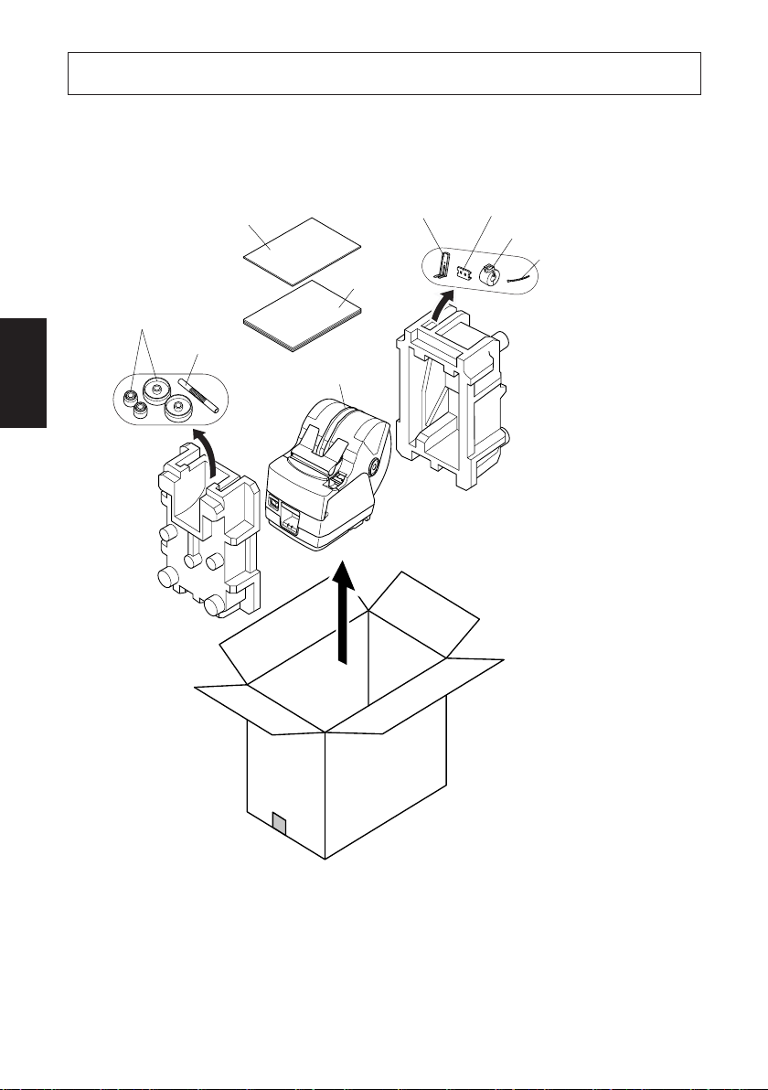
1. Auspacken und Aufstellen
1-1. Überprüfen
Sie den Kartoninhalt, und vergewissern Sie sich, daß alle unten abgebildeten
Teile vorhanden sind.
Rollenpapier-
DEUTSCH
halter *3
Installationsblatt
Papieranschlag
Bedienungsanleitung
Rollenpapierwelle *3
Drucker
Schalterabdeckung
Ferritkern *1
Befestigungsband *2
*1: Nicht mit RS-232C mitgeliefert
*2: Nicht mit RS-232C- und USB
Modellen mitgeliefert
*3: Nur Modell TSP1043
Abb. 1-1 Auspacken
Falls Teile fehlen, wenden Sie sich zwecks Nachlieferung bitte an den Fachhandel, bei dem das Gerät gekauft wurde. Im Hinblick auf einen eventuellen
zukünftigen Transport des Druckers empfiehlt es sich, den Lieferkarton und das
gesamte Verpackungsmaterial aufzubewahren.
– 65 –– 65 –
Page 69
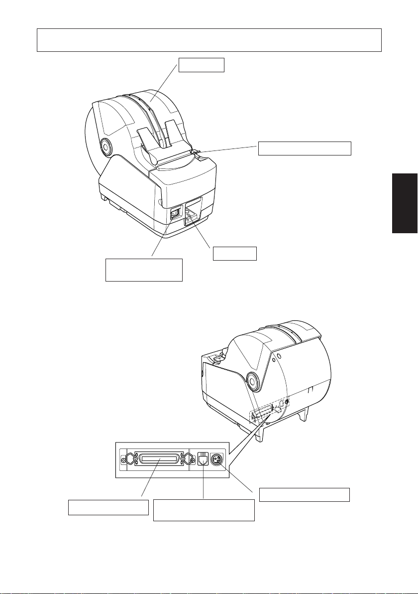
2. Beschreibung und Bezeichnung der Geräteteile
Abdeckung
Diese Abdeckung öffnen, um Papier
einzusetzen oder zu entnehmen.
Abdeckung-öffnen-Hebel
Diesen Hebel in Pfeilrichtung drücken, um die
Druckerabdeckung zu
öffnen.
DEUTSCH
Bedienfeld
Nur Parallel-Schnittschnelle-Modell
Zum Ein- oder Ausschalten des Druckers.
Mit LED-Anzeigen
zur Anzeige des
Druckerstatus und
Schalter zur
Druckerbedienung.
Schnittstellenbuchse
Zum Anschließen an
den Hostcomputer.
Signaltongebereinheit-
Anschluß
Zum Anschluß an eine
Signaltongebereinheit. Nicht
zum Anschluß an ein
Telefon!
– 66 –
Betriebsstromanschluß
Zum Anschließen des
Betriebsstromkabels vom
Netzteil. Den Stecker
nicht bei eingeschaltetem
Drucker abziehen.
Page 70

Wahl eines Aufstellungsorts für den Drucker
Bevor Sie den Drucker auspacken, sollten Sie einige Minuten damit
verbringen, einen geeigneten Aufstellungsort auszusuchen. Denken Sie
dabei an die folgenden Punkte:
✓ Den Drucker auf einem flachen, aber festen Untergrund aufstellen,
wo keine Vibrationen vorhanden sind.
✓ Die verwendete Steckdose soll in der Nähe und frei zugänglich sein.
✓ Sicherstellen, daß der Drucker nahe genug am Computer ist, um die
Geräte mit dem Druckerkabel verbinden zu können.
✓ Sicherstellen, daß der Drucker vor direktem Sonnenlicht geschützt ist.
DEUTSCH
✓ Sicherstellen, daß der Drucker ausreichend weit von Heizkörpern
entfernt steht.
✓ Dafür sorgen, daß die Umgebung des Druckers sauber, trocken und
staubfrei ist.
✓ Sicherstellen, daß der Drucker an eine einwandfreie Stromzufuhr
angeschlossen ist. Er sollte nicht an Steckdosen angeschlossen werden, an denen bereits Geräte mit möglichen Netzstörungen wie
Kopierer, Kühlschränke u.a. angeschlossen sind.
✓ Den Drucker nicht an Orten mit hoher Luftfeuchtigkeit aufstellen.
WARNUNG
✓ Das Gerät sofort ausschalten, wenn es Rauch, ungewöhnliche Gerü-
che und merkwürdige Geräusche abgibt. Sofort das Gerät vom Netz
trennen und den Fachhändler benachrichtigen.
✓ Niemals versuchen, dieses Produkt selber zu reparieren. Unsachge-
mäße Reparaturen können gefährlich sein.
✓ Niemals dieses Produkt zerlegen oder modifizieren. Eingriffe an
diesem Produkt können zu Verletzungen, Bränden oder elektrischen
Schlägen führen.
– 67 –– 67 –
Page 71

3. Verbrauchsteile und Netzteil
Wenn die Verbrauchsteile verbraucht sind, besorgen Sie Ersatz entsprechend der
unten gezeigten Tabelle.
Verwendung von Verbrauchsteilen oder Netzteilen, die nicht den unten aufgeführten Beschreibungen entsprechend, kann zu Schäden am Drucker, Bränden
oder elektrischen Schlägen führen.
(1) Rollenpapierbeschreibung
Thermopapier
µ
Dicke: 65 bis 150
Breite: 44,5±0,5 bis 82,5±0,5 mm
Rollen-Außendurchmesser
: Max. ø180 mm
(Bei Gebrauch von Drop-In-Rollenpapierwechsel)
: Max. ø170 mm
(Bei Gebrauch der Rollenpapierwelle)
Breite der Aufnehmerpapierrolle: 45 bis 83 mm
Kern Außen/Innen-Durchmesser
Papierstärke Kern außen Kern innen
65 – 100 µm Max. ø40±1 mm Max. ø25,4±1 mm
100 – 150 µm Max. ø58±1 mm Max. ø50,8±1 mm
Druckfläche: Äußere Papierkante
Behandlung der Papierendkante:Nicht Paste oder Kleber zum Befesti-
(2) Empfohlenes Papier
Mitsubishi Paper Mills Ltd.
T8037 (tickets), 85 µm (Dicke)
TF8067 (tickets), 84 µm (Dicke)
TF8075 (tickets), 85 µm (Dicke)
KANZAN
KLS46 (tickets)
KPO460 (tickets)
Kanzaki Specialty Papers Inc. (KSP)
Lotto482 (tickets), 84 µm (Dicke)
Je nach Typ und Stärke des Papiers kann es erforderlich sein, die Einstellungen
für die Druckintensität zu ändern. Zum Ändern der Intensitätseinstellung den
Druckintensität-Befehle <ESC><RS>‘d’n oder Speichesschalter-Einstellungen
verwenden. Einzelheiten siehe getrennte Spezifikationsanleitung.
m
+0,5
-1
+0,5
-1
gen von Papierrolle oder Kern verwenden.
Nicht die Papierendkante falten.
– 68 –
DEUTSCH
Page 72

(3) Netzteil (Option)
ACHTUNG
DEUTSCH
Modelbezeichnung: PS60
Eingang: 100 bis 240 V WS, 50/60 Hz
Ausgang:
24 V GS±5%, max. 2,0 A (max. 10 s bei 5,0 A Last)
Empfehlungen zu den zu verwendenden Papiersorten sind im Internet
bei der folgenden URL erhältlich:
http://www.star-m.jp/eng/dl/dl02.htm
– 69 –– 69 –
Page 73
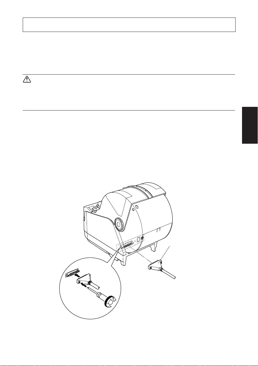
4. Anschlußkabel und Netzteil
4-1. Schnittstellenkabel
Beachten Sie, daß das Schnittstellenkabel nicht mitgeliefert ist. Bitte verwenden
Sie ein Kabel, das den Spezifikationen entspricht.
ACHTUNG
Vor dem Anschließen/Abtrennen des Schnittstellenkabels stellen Sie
sicher, daß der Drucker und alle angeschlossenen Gerät ausgeschaltet
sind. Außerdem sollte der Netzstecker abgezogen sein.
4-1-1. Serielles Schnittstellenkabel (RS-232C)
(1)Stellen Sie sicher, daß der Drucker ausgeschaltet ist.
(2)Schließen Sie das Schnittstellenkabel an die Buchse an der Rückseite des
Druckers an.
(3)Befestigen Sie die Steckerk-Schrauben.
Serielles Schnittstellenkabel
DEUTSCH
– 70 –
Page 74

4-1-2. Parallele Schnittstelle
Ferritkern
DEUTSCH
Kable
(1)Stellen Sie sicher, daß der Drucker
ausgeschaltet ist.
(2)Nur beim Parallel-Schnittschnelle-
Modell, Befestigen Sie den großen
Ferritkern am Kabel, wie das in der
folgenden Abbildung gezeigt wird.
Maximum 5 cm
Kabelbinder
Ziehen und
abschneiden
(3)Führen Sie den Kabelbinder durch
den Ferritkern.
(4)Führen Sie den Kabelbinder um das
Kabel und sperren Sie ihn.
Schneiden Sie überschüssiges Band
mit einer Schere ab.
– 71 –– 71 –
Page 75

(5)Schließen Sie das Schnittstellenkabel an die Buchse an der Rückseite des
Druckers an.
(6)Befestigen Sie die Steckerklammern.
Paralleles Schnittstellenkabel
4-1-3. Anschließen des USB-Kabels
(1)Stellen Sie sicher, daß der Drucker ausgeschaltet ist.
(2)Bringen Sie den Ferritkern am USB-Kabel an, wie in der Abbildung unten
gezeigt und stellen Sie sicher, das Kabel durch die Kabelhalterung zu führen,
wie in der Abbildung gezeigt.
DEUTSCH
– 72 –
Page 76
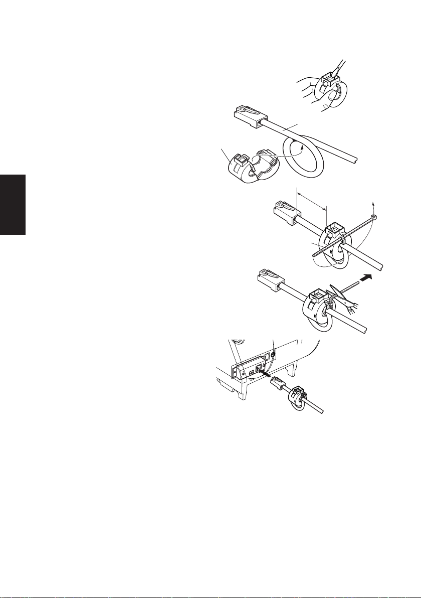
4-1-4. Anschließen des Ethernet-Kabels
(1)Stellen Sie sicher, daß der Drucker
ausgeschaltet ist.
(2)Bringen Sie den Ferritkern auf dem
Ethernet-Kabel an, wie in der Abbildung unten gezeigt.
DEUTSCH
(3)Führen Sie die Befestigung durch
den Ferritkern.
(4)Führen Sie das Befestigungsteil um
das Kabel und sperren es. Schneiden Sie überstehende Teile ab.
(5)Schließen Sie das Ethernet-Kabel
am Stecker an der Schnittstellenkarte an.
Dann verbinden Sie das andere Ende
des Kabels mit Ihrem Computer.
Ethernet-Kabel
Ferritkern
10 cm
(Maximum)
Befestigungsteil
– 73 –– 73 –
Page 77

4-2. Anschließen an eine Signaltongebereinheit
Sie können eine Signaltongebereinheit mit einem Modularstecker an den Drukker anschließen. Im folgenden wird die Herstellung der Verbindung beschrieben.
Siehe “Modularstecker” auf Seite 149 für den Typ von Modularstecker, der dazu
erforderlich ist. Beachten Sie, daß der Drucker nicht mit einem Modularstecker
oder Kabel ausgestattet ist. Diese Teile müssen vom Anwender besorgt werden.
ACHTUNG
Vor dem Anschließen der Kabel sicherstellen, daß der Drucker ausgeschaltet und vom Netz getrennt ist.
Schließen Sie das Signaltongebereinheit-Kabel am Stecker an der Rückseite des
Druckers an.
ACHTUNG
Schließen Sie keine Telefonleitung am Signaltongebereinheit-Anschluß
an. Wenn dies nicht beachtet wird, kann der Drucker beschädigt werden.
Aus Sicherheitsgründen dürfen Sie auch nicht die Verdrahtung am
Signaltongebereinheit-Anschluß anschließen, falls sie zu hohe Spannung führt.
DEUTSCH
– 74 –
Page 78

4-3. Anschließen des optionalen Netzteils
Hinweis:Vor dem Anschließen/Abtrennen des Netzteils stellen Sie sicher,
daß der Drucker und alle angeschlossenen Gerät ausgeschaltet sind.
Außerdem sollte der Netzstecker abgezogen sein.
(1)Schließen Sie das Netzteil an das Netzkabel an.
Hinweis:Verwenden Sie nur das vorgesehene Netzteil und Netzkabel.
(2)Das Netzteil am Stecker des Druckers anschließen.
(3)Stecken Sie den Netzstecker des Netzteils in eine Steckdose ein.
DEUTSCH
ACHTUNG
Beim Abziehen des Kabels immer am Stecker ziehen
und nicht am Kabel. Durch das Lösen der Verriegelung wird das Abziehen des Steckers leicht möglich.
Wenn stark am Kabel selber gezogen wird, kann der
Stecker beschädigt werden.
– 75 –– 75 –
Page 79

4-4. Einschalten
Stellen Sie sicher, daß das Netzteil angeschlossen ist, wie in 4-3 beschrieben.
(1)Den Netzschalter vorne am Gerät auf Ein (ON) stellen. Das POWER-
Lämpchen am Bedienfeld leuchtet auf.
Netzschalter
ACHTUNG
Wir empfehlen, den Netzstecker aus der Steckdose zu ziehen, wenn der
Drucker längere Zeit lang nicht benutzt werden soll. Der Drucker sollte
vorzugsweise an einem Platz aufgestellt werden, der leichten Zugang zur
Netzsteckdose gewährt.
DEUTSCH
– 76 –
Page 80
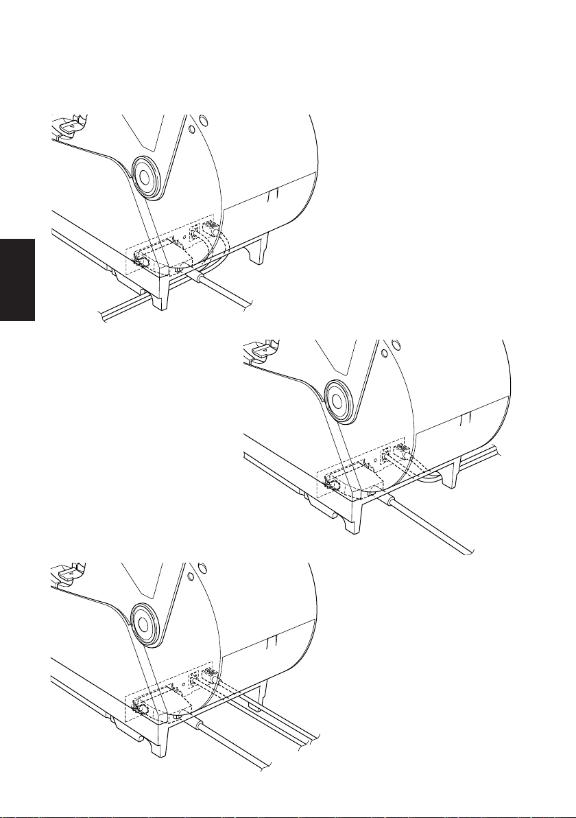
4-5. Installieren der Kabel
Installieren Sie die Kabel wie in den nachfolgenden Abbildungen dargestellt.
DEUTSCH
– 77 –– 77 –
Page 81

4-6. Einsetzen der Schalterabdeckung
Es ist nicht notwendig, die Schalterabdeckung zu verwenden. Setzen Sie diese
nur ein, wenn für Sie erforderlich ist, daß
• der Netzschalter nicht versehentlich betätigt werden kann,
• der Netzschalter nicht mehr so einfach von anderen Personen betätigt
werden kann.
Setzen Sie die Schalterabdeckung wie in den nachfolgenden Abbildungen
dargestellt ein.
DEUTSCH
Der Netzschalter kann durch Einführen eines spitzigen Gegenstandes (Kugelschreiber usw.) in die Aussparungen der Schalterabdeckung ein- (!) und
ausgeschaltet (O) werden.
ACHTUNG
Wir empfehlen, den Netzstecker aus der Steckdose zu ziehen, wenn der
Drucker längere Zeit lang nicht benutzt werden soll. Der Drucker sollte
vorzugsweise an einem Platz aufgestellt werden, der leichten Zugang zur
Netzsteckdose gewährt.
– 78 –
Page 82
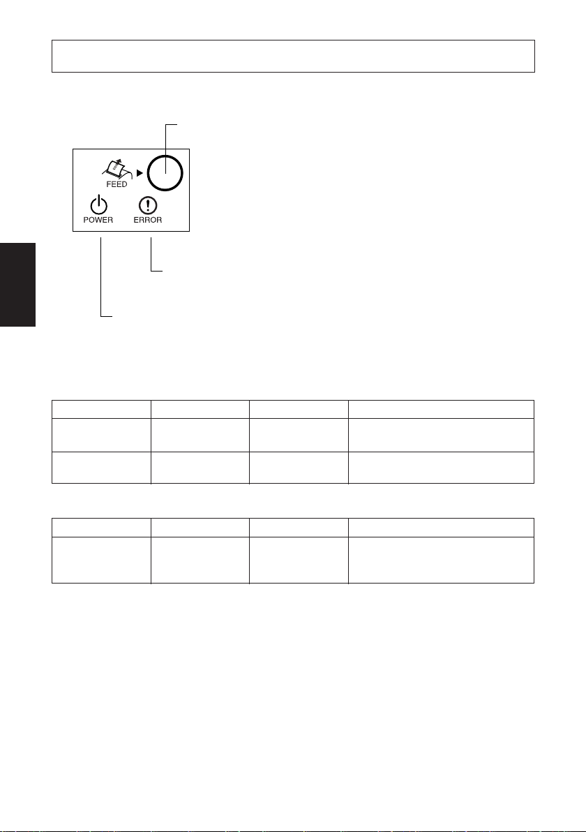
5. Bedienfeld und andere Funktionen
5-1. Bedienfeld
DEUTSCH
3 ERROR-Lämpchen
1 POWER-Lämpchen
(grüne LED)
5-2. Fehler
1) Automatisch behebbare Fehler
Fehlerbeschreibung
Erkennung hoher
Kopftemperatur
Abdeckung-Offen-
Fehler
2) Behebbare Fehler
Fehlerbeschreibung
Papierschnitt-Feh-
ler
Hinweis:
1) Wenn das Schneidwerk nicht in Grundstellung zurückkehrt oder nicht die
Anfangsbewegung ausführt, ist Behebung nicht möglich.
2) Wenn Papierstau vorliegt, ausschalten, den Papierstau beheben, und dann
wieder einschalten.
POWER-Lämpchen
Blinkt in Abstän-
den von 0,5 s
Ein
POWER-Lämpchen
Aus
2 FEED-Taste
(rote LED)
1 POWER-Lämpchen (grüne LED)
Leuchtet in eingeschaltetem Zustand
2 FEED-Taste
Die FEED-Taste drücken, um das
Rollenpapier vorzutransportieren.
3 ERROR-Lämpchen (rote LED)
Zeigt in Kombination mit dem POWER-Lämpchen verschiedene
Fehlerzustände an.
ERROR-Lämpchen
Aus
Ein
ERROR-Lämpchen
Blinkt im Abstand
von 0,125 s
Behebungsbedingungen
Automatische Behebung nach Ab-
kühlen es Druckkopfes.
Automatische Behebung nach Schlie-
ßen der Druckerabdeckung.
Behebungsbedingungen
Behoben, wenn des Schneidwerk nach
dem Ein- und Ausschalten in Grundstellung zurückkehrt.
– 79 –– 79 –
Page 83

(3) Nicht behebbare Fehler
Fehlerbeschreibung
Papierschnitt-Feh-
ler
EERROM-Fehler
Flash-ROMFehler
Thermistor-Fehler
StromversorgungFehler
POWER-Lämpchen
Aus
Aus
Aus
Aus
Aus
ERROR-Lämpchen
Blinkt im Abstand
von 1,0 s
Blinkt im Abstand
von 0,75 s
Blinkt im Abstand
von 0,5 s
Blinkt im Abstand
von 1,5 s
Blinkt im Abstand
von 2 s
Behebungsbedingungen
Dies ist ein nicht behebbarer Fehler.
Der Kundendienst muß bezüglich
Reparatur kontaktiert werden.
Dies ist ein nicht behebbarer Fehler.
Der Kundendienst muß bezüglich
Reparatur kontaktiert werden.
Dies ist ein nicht behebbarer Fehler.
Der Kundendienst muß bezüglich
Reparatur kontaktiert werden.
Dies ist ein nicht behebbarer Fehler.
Der Kundendienst muß bezüglich
Reparatur kontaktiert werden.
Dies ist ein nicht behebbarer Fehler.
Der Kundendienst muß bezüglich
Reparatur kontaktiert werden.
Hinweis:
1) Wenn ein nicht behebbarer Fehler auftritt, das Gerät sofort ausschalten.
2) Wenn ein Stromversorgung-Fehler auftritt, besteht die Möglichkeit, daß
die Netzversorgung nicht richtig ist.
Bei anderen nicht behebbaren Fehlern muß der Kundendienst bezüglich
Reparatur kontaktiert werden.
DEUTSCH
(4) Papiererkennung-Fehler
Fehlerbeschreibung
Papierschnitt-Feh-
ler
Papierrollenende
fast erreicht
POWER-Lämpchen
Ein
Ein
ERROR-Lämpchen
Blinkt im Abstand
von 0,5 s
Blinkt im Abstand
von 2 s
– 80 –
Behebungsbedingungen
Automatische Behebung durch Ein-
legen einer neuen Papierrolle und
Schließen der Druckerabdeckung.
Die Anzeigen zeigen, daß das Ende
der Papierrolle sich nähert, aber der
Drucker druckt weiter.
Page 84
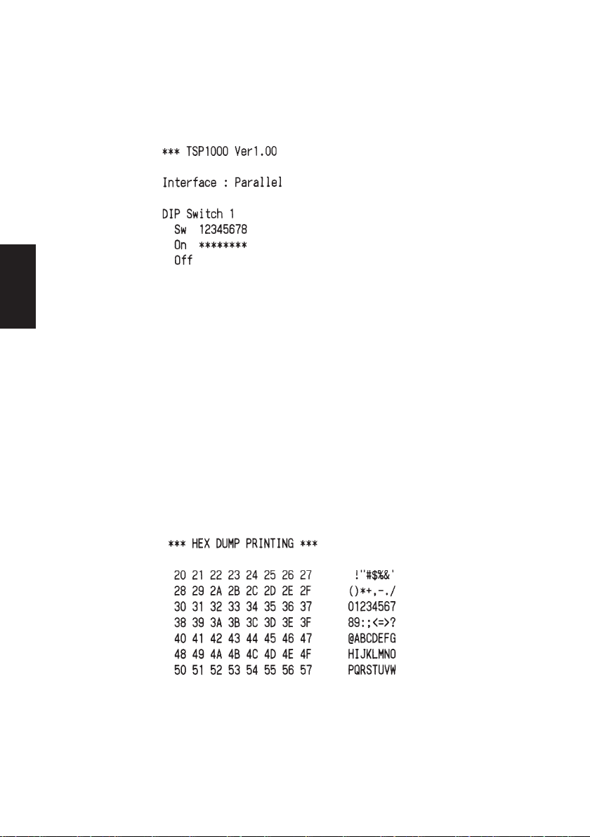
5-3. Selbstdruck
(1)Testdruck
Das Gerät einschalten, während die FEED-Taste gedrückt gehalten wird.
Der Testdruck wird entsprechend der Ver. Nr., den DIP-Schalter-Einstellungen und den Speicherschalter-Einstellungen ausgeführt.
DEUTSCH
(2) Sedezimaler Datenausdruck
Die Druckerabdeckung öffnen, und dann einschalten, während die FEEDTaste gedrückt gehalten wird. Wenn die Abdeckung geschlossen wird, wird
“***HEX DUMP PRINTING***” ausgedruckt, und der Drucker schaltet auf
die Betriebsart sedezimaler Datenausdruck um.
Jedes der vom Computer zum Drucker gesandten Signale wird nun als
sedezimaler Code ausgedruckt.
Diese Funktion erlaubt es, zu prüfen, ob ein von der Sowa zum Drucker
gesandter Steuercode korrekt ist oder nicht. Die letzte Zeile wird nicht
ausgedruckt, wenn Daten für weniger als eine ganze Zeile vorhanden sind.
Wenn die FEED-Taste gedrückt wird, wird aber auch die letzte Zeile ausgedruckt. Zum Ausschalten dieser Betriebsart ist es erforderlich, den Drucker
vollständig auszuschalten.
– 81 –– 81 –
Page 85
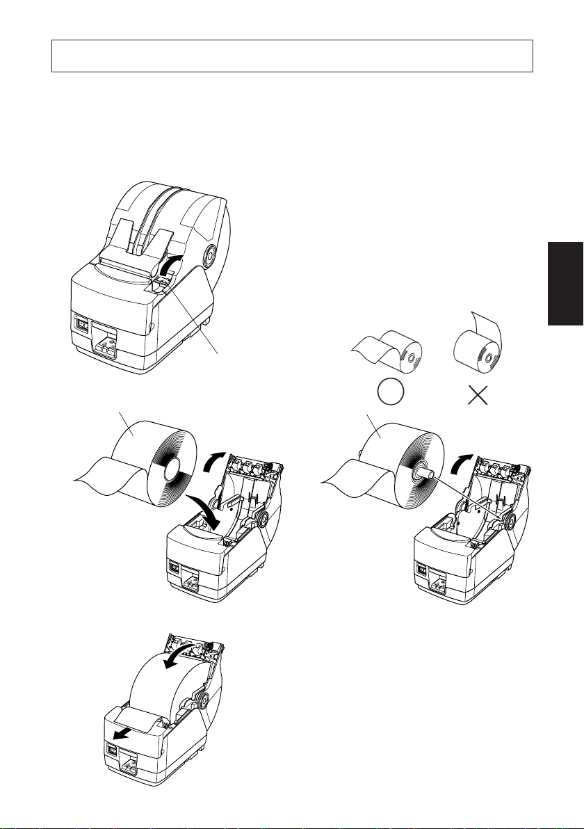
6. Einlegen der Papierrolle
6-1. Einlegen des Rollenpapiers
Das Einlegen des Rollenpapiers erfolgt je nach benutztem Papier (Drop-InRollenpapier oder Rollenpapier, für das die Welle erforderlich ist) unterschiedlich.
Legen Sie das Rollenpapier gemäß den Verfahren in Abschnitt 6-2 ein.
(1)Den Abdeckung-Öffnen-Hebel
drücken, und die Druckerabdeckung
öffnen.
(2)Unter Beachtung der richtigen Ein-
setzrichtung der Rolle die Papierrolle in die Vertiefung legen und die
Vorderkante des Papiers nach vorne ziehen.
AbdeckungÖffnen-Hebel
DEUTSCH
Rollenpapier
[Drop-In-Papierwechsel]
Rollenpapier
[Mit Welle]
– 82 –
Page 86

DEUTSCH
Position 1
Position 2
Position 3
Position 4
Position 5
Position 6
(3)Ziehen Sie an der Papierkante, um
Durchhang zu beseitign und drük-
ken Sie dann beide Seiten der
Druckerabdeckung zum Schließen
nach unten.
Hinweis: Sicherstellen, daß die
Druckerabdeckung fest geschlossen ist.
(4)Wenn die Druckerabdeckung nach
dem Einschalten geschlossen wird,
arbeitet das Schneidwerk automatisch, und das vordere Papierende
wird abgeschnitten.
Hinweis: Wenn das Schneidwerk
nach dem Schließen der Druckerabdeckung nicht arbeitet, öffnen Sie die
Abdeckung und schließen sie wieder.
(5) Wenn erforderlich bringen Sie den
Papieranschlag an der Papierabdeckung wie gezeigt an. Das Ausgabefach kan bis zu 30 Blatt fassen
(Breite: 80–82,5 mm, Dicke: 80–
120 mm, Länge: 50–150 mm). Bei
Papier mit anderer Stärke oder anderen Blattlängen höchstens 10
Blatt.
Hinweis: Beim Anbringen des
Papieranschlags an der Papierabdeckung positionieren Sie den Anschlag entsprechend der Länge des
abzuschneidenden Papiers. (Siehe
folgende Tabelle.)
Papierlänge (mm)
Position 1 50 – 100
Position 2 100 – 120
Position 3 120 – 140
Position 4 140 – 160
Position 5 160 – 180
Position 6 180 – 200
– 83 –– 83 –
Page 87

WARNUNG
• Nicht die Schneidwerkklinge berühren.
- Im Papierauslaßschlitz befindet sich ein Schneidwerk. Niemals die
Hände in den Auslaßschlitz stecken, nicht nur während des Druckbetriebs sondern auch wenn der Drucker nicht arbeitet.
- Die Druckerabdeckung kann geöffnet werden, wenn das Papier
ausgetauscht wird. Da das Schneidwerk im Inneren der Druckerabdeckung ist, darauf achten, nicht das Gesicht oder die Hände zu
nahe an das Schneidwerkmesser zu bringen.
• Während des Druckens und kurz nach dem Drucken kann der Bereich
um den Thermalkopf sehr heiß werden. Nicht das Heizelement mit der
Hand berühren.
ACHTUNG
• Nicht den Lösehebel der Abdeckung betätigen, während mit der Hand
auf die Druckerabdeckung gedrückt wird.
• Nicht das Papier bei geschlossener Druckerabdeckung herausziehen.
• Das Heizelement und der Treiber-Chip des Thermalkopfes werden
leicht beschädigt. Diese Teile nicht mit Metallgegenständen, Sandpapier usw. berühren.
• Die Druckqualität kann nachlassen, wenn das ThermalkopfHeizelement durch Berührung mit der Hand verschmutzt wird. Nicht
das Thermalkopf-Heizelement berühren.
• Es besteht die Gefahr von Schäden am Treiber-Chip durch statische
Elektrizität. Niemals den Chip direkt berühren.
• Die Druckqualität und die Lebensdauer des Thermalkopfes kann
nicht garantiert werden, wenn anderes als Papier der vorgeschriebenen Sorte verwendete wird. Insbesondere Papier mit [Na+, K+, C1-]
kann die Lebensdauer des Thermalkopfes drastisch verkürzen. Bitte
vorsichtig arbeiten.
• Nicht den Drucker betreiben, wenn Feuchtigkeit durch Beschlag usw.
an der Vorderseite des Druckkopfes vorhanden ist.
DEUTSCH
– 84 –
Page 88

6-2. Verfahren zum Papiereinlegen
Bei diesem Drucker gibt es zwei Verfahren zum Papiereinlegen: eins mit
Rollenpapierwelle und eins ohne Welle. Die Rollenpapierwelle wird bei DropIn-Papierwechsel nicht benutzt. Wählen Sie das Papiereinlegeverfahren aus
folgender Tabelle je nach benutztem Papier.
Papierstärke (µm)
DEUTSCH
Hinweis:
*1: Maximaler Rollen-Außendurchmesser: 150 mm
*2: Maximaler Rollen-Außendurchmesser: 170 mm
*3: Maximaler Rollen-Außendurchmesser: 180 mm
*4: Die Druckgeschwindigkeit muß von hoher Geschwindigkeit (Werksein-
Papierbreite (mm)
65 Stärke < 80
Stärke 120
80
120 < Stärke
150
44,5 Breite < 79,5 79,5 Breite 82,5
Rollenpapierwelle benutzen
(*1, *4)
Rollenpapierwelle benutzen
(*1, *4)
Rollenpapierwelle benutzen
(*1)
Rollenpapierwelle benutzen
(*2)
Drop-In-Papierwechsel benutzen (*3)
Rollenpapierwelle benutzen
(*1)
stellung) auf mittlere Geschwindigkeit (140 mm/s) herabgesetzt werden.
Zum Ändern der Druckgeschwindigkeit den DruckgeschwindigkeitsBefehl <ESC><RS> Rn verwenden. Einzelheiten siehe getrennte
Spezifikationsanleitung.
– 85 –– 85 –
Page 89

6-3. Einstellen des Rollenpapierhalters
Es gibt Rollenpapierhalter in zwei unterschiedlichen Größen: Rollenpapierhalter
1 für Papier mit einem Kern-Innendurchmesser von 1 Zoll und Rollenpapierhalter 2 für Papier mit einem Kern-Innendurchmesser von 2 Zoll. Wählen Sie die
Papierhalter je nach Größe der verwendeten Papierrolle.
(1) Die Papierrollenhalter auf beide Enden der Rollenpapierwelle aufsetzen.
(2) Die Positionen der Rollenpapierhalter je nach Breite des benutzten Rollen-
papiers einstellen.
(3) Die Rollenpapierhalter und -welle in das Rollenpapier einsetzen.
Rollenpapierwelle
Rollenpapierhalter 2
Rollenpapierwelle
DEUTSCH
– 86 –
Rollenpapierhalter 1
Page 90

6-4. Einstellen der Papierführung
Bei Lieferung sind die Papierführungen und oberen Führungen für Rollenpapier
mit folgender Breite eingestellt.
Papierbreite: 79,5 ± 0,5 mm (TSP1043)
Papierbreite: 82,5 ± 0,5 mm (TSP1045)
Wenn Sie Rollenpapier mit einer anderen Breite als oben angegeben verwenden,
führen Sie folgendes Verfahren aus, um die Papierführungen einzustellen. Zum
Einstellen der oberen Führungen, siehe “6-5 Einstellen der oberen Führungen”.
(1) Die vier Schrauben lösen.
DEUTSCH
(2) Die linke und rechte Papierführung je nach Breite des Rollenpapiers einstel-
len. Achten Sie dabei darauf, 0,5 mm Abstand zwischen den Führungen und
der Papierkante zu lassen.
Die Skalen auf der Metallplatte im Drucker sind in 1 mm-Abschnitte zwischen
Markierungen unterteilt. Die beiden Markierungen oberhalb der
den
Skalen werden für 57,5 mm breites Papier und die beiden
79,5 mm breites Papier verwendet. Setzen Sie bei 79,5 mm breitem Rollenpapier jede Papierführung daher 0,5 mm von der entsprechenden
rung entfernt nach außen. Die Schrauben 2 und 3 können gegebenenfalls
gelöst und in die daneben liegenden Schraubenlöcher eingesetzt werden.
(3) Die vier Schrauben festziehen.
Markierungen für
Markie-
Linke Papierführung
Schraube 1
Rechte Papierführung
Schraube 2
Schraube 4Schraube 3
– 87 –– 87 –
Page 91

6-5. Einstellen der oberen Führung
Bei Lieferung sind die oberen Führungen für Rollenpapier mit einer Breite von
79,5–82,5 mm eingestellt. Wenn Sie Rollenpapier mit einer anderen Breite
verwenden möchten, führen Sie folgendes Verfahren aus, um die oberen Führun-
gen einzustellen.
(1)Die beiden Schrauben für die linke und rechte obere Führung lösen.
(2)Die linke und rechte obere Führung je nach Breite des Rollenpapiers einstel-
len. Achten Sie dabei darauf, daß jede Führung die Papierkante um etwa 2 mm
überlappt.
Die Skalen auf der Metallplatte an der Abdeckung sind in 1 mm-Abschnitte
unterteilt. Die beiden
57,5 mm breites Papier und die beiden
Papier (auch bei 82,5 mm breitem Papier) verwendet.
Die Schrauben für die linke und rechte obere Führung können gegebenenfalls
gelöst und in die daneben liegenden Schraubenlöcher eingesetzt werden.
Wenn die Rollenpapierbreite 50 mm oder weniger beträgt, die mittlere obere
Führung ausbauen, indem Sie die Schraube lösen, und dann die linke und
rechte obere Führung einstellen.
Hinweis:
Vermeiden Sie beim Einstellen der oberen Führungen, die Kabel einzuklemmen oder zu quetschen.
(3)Die zwei Schrauben festziehen.
Markierungen unterhalb der Skalen werden für
Markierungen für 79,5 mm breites
DEUTSCH
Schrauben
– 88 –
2mm
2mm
Page 92
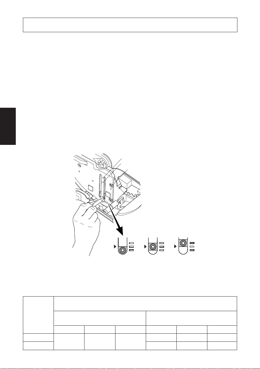
7. Einstellung des Endanäherungs-Sensors
Den Endanäherungs-Sensor auf folgende Weise justieren, damit er der Größe der
verwendeten Papierrolle entspricht.
1 Die Druckerabdeckung öffnen.
2 Bestimmen Sie die korrekte Position des Einstellers unter den folgenden drei
Positionen je nach Papiereinlegeverfahren und Kern-Innendurchmesser des
Rollenpapiers.
Position 1: Bei Drop-In-Papierwechsel
DEUTSCH
Position 2: Bei Rollenpapierhalter 2 (ø50,8 mm Kern innen)
Position 3: Bei Rollenpapierhalter 1 (ø25,4 mm Kern innen)
3 Die Spitze eines Kugelschreibers o.ä. Gegenstands in das Loch des Einstellers
stecken, und dann eindrücken und den Einsteller auf die gewünschte Einstellung schieben.
Position 3
Position 2
Position 1
(Stufe 1) (Stufe 3)(Stufe 2)
Die Restmenge von Papier, das erkannt wird, ist in nachfolgender Tabelle
aufgeführt.
(1) Position 1
Bei Gebrauch von Rollenpapier mit einem Kern-Innendurchmesser (A): ø25,4 und
Papierdicke
µ
m)
(
80
105
Kern-Außendurchmesser (B): ø40
Erkannter Durchmesser (C)
(Etwa mm)
Stufe 1 Stufe 2 Stufe 3 Stufe 1 Stufe 2 Stufe 3
ø44 ø48 ø52
– 89 –– 89 –
Restpapierlänge
(Etwa m)
3,5 7,5 12,5
1,5 4,5 7,5
Page 93

(2)Position 2
Papierdicke
(
µ
m)
65
80
105
(3)Position 3
Papierdicke
µ
m)
(
150
Bei Gebrauch von Rollenpapier mit einem Kern-Innendurchmesser (A): ø25,4 und
Kern-Außendurchmesser (B): ø40
Erkannter Durchmesser (C)
(Etwa mm)
Stufe 1 Stufe 2 Stufe 3 Stufe 1 Stufe 2 Stufe 3
—ø45 ——4,4 —
Bei Gebrauch von Rollenpapier mit einem Kern-Innendurchmesser (A): ø50,8 und
Kern-Außendurchmesser (B): ø58
Erkannter Durchmesser (C)
(Etwa mm)
Stufe 1 Stufe 2 Stufe 3 Stufe 1 Stufe 2 Stufe 3
—ø69 ——6,5 —
Restpapierlänge
(Etwa m)
5,6
3,2
Restpapierlänge
(Etwa m)
DEUTSCH
B
A
Kern der
Papierrolle
C
Hinweis:
1) Vor der Lieferung wird der Einsteller auf Position 1, Level 2 eingestellt.
2) Die Abmessung C und die restliche
Papierlänge sind berechnete Werte.
Es können leichte Abweichungen
zum tatsächlichen Wert auftreten.
3) Die restlichen in der Tabelle oben
gezeigten Papierlängen dienen nur
zur Orientierung. Stellen Sie den
Papierende-Sensor entsprechend
den aktuellen Verwendungsbedingungen ein.
C
4) Wird starkes Papier (100 µm oder
stärker) verwendet, wenn der Einsteller auf position 1 gesetzt ist, sitzt
das Rollenpapier lose und es kann
leichter zu Erkennungsfehlern kommen. Auf Stufe 3 stellen.
– 90 –
Page 94

8. Verhindern und Beheben von Papierstau
8-1. Verhindern von Papierstau
Das Papier soll beim Ausgeben und vor dem Schneiden nicht berührt werden.
Wenn das Papier beim Ausgeben gedrückt oder gezogen wird, kann ein Papierstau, ein Abschneidfehler oder ein Zeilenvorschubfehler verursacht werden.
8-2. Beheben von Papierstau
Wenn ein Papierstau auftritt, beheben Sie ihn wie folgt.
DEUTSCH
(1)Stellen Sie den Netzschalter auf Aus, um den Drucker auszuschalten.
(2)Drücken Sie den Abdeckung-Öffnen-Hebel, und öffnen Sie die Druckerab-
deckung.
Wenn die Druckerabdeckung sich bei Modellen mit automatischer Abschneideinheit nicht öffnet, bedeutet dies, daß die automatische Abschneideinheit nicht in Grundstellung ist. In diesem Fall die automatische Abschneideinheit entsprechend den in Abschnitt 8-3 gegebenen Anweisungen auf
Grundstellung zurückstellen. Dann die Druckerabdeckung öffnen, nachdem
der Papierstau behoben ist.
(3)Entfernen Sie das gestaute Papier.
ACHTUNG
Achten Sie darauf, den Drucker beim Entfernen des gestauten Papiers
nicht zu beschädigen. Insbesondere der Thermaldruckkopf läßt sich
leicht beschädigen; achten Sie darauf, ihn nicht zu berühren.
(4) Stellen Sie sicher, daß das Papier gerade ausgerichtet ist, und schließen Sie die
Druckerabdeckung vorsichtig.
Hinweis:
1) Stellen Sie sicher, daß das Papier gerade ausgerichtet ist. Wenn die
Druckerabdeckung bei schief liegendem Papier geschlossen wird, kann
ein Papierstau auftreten.
2) Sperren Sie die Druckerabdeckung durch Drücken auf beide Seiten.
Sicherstellen, daß die Abdeckung richtig geschlossen ist.
(5)Stellen Sie den Netzschalter in Ein-Stellung, um den Drucker einzuschalten.
Stellen Sie sicher, daß die ERROR-LED nicht leuchtet.
Hinweis:Während die ERROR-LED leuchtet, akzeptiert der Drucker keine
Befehle wie Druckbefehl; stellen Sie deshalb sicher, daß die Abdeckung richtig geschlossen ist.
– 91 –– 91 –
Page 95

8-3. Freigeben eines gesperrten Schneidmessers
Wenn das automatische Schneidmesser sperrt oder das Papier nicht schneidet,
wie folgt verfahren.
WARNUNG
Da Arbeiten am Schneidmesser gefährlich sein können, immer zuerst
den Drucker ausschalten.
(1)Den Netzschalter auf Aus (OFF) stellen, um den Drucker auszuschalten.
(2)Die Frontabdeckung abschieben, um das Schneidmesser freizulegen.
(3)Gestautes Papier entfernen.
ACHTUNG
Darauf achten, nicht den Drucker nicht beim Entfernen von gestautem
Papier zu beschädigen.
Da der Thermalkopf besonders empfindlich ist, darauf achten, ihn nicht
zu berühren.
Frontabdeckung
DEUTSCH
– 92 –
Page 96
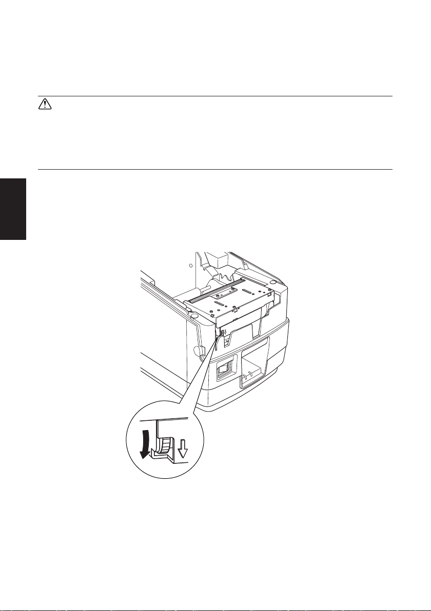
(4)Wenn die bewegliche Klinge des Schneidmessers hervorsteht, den knopf in
Pfeilrichtung drehen, und die bewegliche Klinge in Grundstellung zurückstel-
len. Wenn das Prüffenster vollständig weiß ist, ist die bewegliche Klinge in
Grundstellung.
ACHTUNG
1) Nicht starken Druck auf die bewegliche Klinge ausüben.
2) Wenn die bewegliche Klinge zu sehr hervorsteht, kann die Druckerabdeckung nicht geöffnet werden. Wenn versucht wird, die Abdekkung zu öffnen, kann das Schneidmesser beschädigt werden.
DEUTSCH
(5)Die Druckerabdeckung öffnen, gestautes Papier entfernen, und dann die
Papierrolle wieder einsetzen.
(6)Die Frontabdeckung wieder einsetzen, und den Netzschalter auch Ein (ON)
stellen.
– 93 –– 93 –
Page 97

9. Regelmäßige Reinigung
Die Druckzeichen können durch Ansammlung von Papierstaub und anderem
Schmutz unscharf werden. Um das zu verhindern, muß im Papierhalter und in der
Papiertransportstufe angesammelter Staub von Zeit zu Zeit entfernt werden.
Diese Reinigung sollte einmal alle sechs Monate oder einmal nach jeder Million
Zeilen ausgeführt werden.
9-1. Reinigen des Thermalkopfes
Zum Entfernen von schwärzlichem Staub auf der Oberfläche des Thermalkopfes
diesen mit Isopropylalkohol (IPA) abwischen.
Hinweis:Der Thermalkopf läßt sich leicht beschädigen. Zum Abwischen
immer einen sehr weichen Lappen verwenden und sicherstellen,
daß er nicht zerkratzt wird.
9-2. Reinigen des Papierhalters
Verwenden Sie einen weichen Lappen zur Entfernung von Papierstaub vom
Papierhalter und aus der Papiertransportstufe.
DEUTSCH
– 94 –
Page 98

DEUTSCH
– 95 –– 95 –
Page 99

INDICE
1. Disimballaggio e installazione ......................................................................97
1-1. Disimballaggio .....................................................................................97
2. Identificazione delle parti e nomenclatura .................................................. 98
3. Parti soggette a consumo e trasformatore CA ..........................................100
4. Cavi di collegamento e trasformatore CA .................................................102
4-1. Cavo interfaccia ................................................................................. 102
4-2. Collegamento ad un’unità cicalino ....................................................106
4-3. Collegamento del trasformatore CA opzionale..................................107
4-4. Accensione .........................................................................................108
4-5. Installazione del cavo .........................................................................109
4-6. Installazione mascherina dell’interruttore..........................................110
5. Pannello di controllo e altre funzioni .........................................................111
5-1. Pannello di controllo ..........................................................................111
5-2. Errori ..................................................................................................111
5-3. Stampa automatica .............................................................................113
6. Inserimento del rotolo di carta ...................................................................114
6-1. Inserimento del rotolo di carta ...........................................................114
6-2. Metodi di inserimento carta ............................................................... 117
6-3. Regolazione dei fermi del rotolo di carta ...........................................118
6-4. Regolazione delle guide della carta ...................................................119
6-5. Regolazione delle guide superiori ......................................................120
7. Regolazione del sensore di esaurimento prossimo ....................................121
8. Prevenzione e soluzione degli inceppamenti della carta ..........................123
8-1. Prevenzione degli inceppamenti della carta .......................................123
8-2. Eliminazione degli inceppamenti della carta .....................................123
8-3. Rilascio della taglierina bloccata .......................................................124
9. Pulizia periodica .......................................................................................... 126
9-1. Pulizia della testina termica ...............................................................126
9-2. Pulizia del comparto carta ..................................................................126
APPENDICE ....................................................................................................128
ITALIANO
L’Appendice appare solo nella sezione in inglese di questo manuale.
Visitare il seguente indirizzo URL
http://www.star-m.jp/eng/dl/dl02.htm
per accedere alla versione più recente del manuale.
– 96 –
Page 100

1. Disimballaggio e installazione
1-1. Disimballaggio
Dopo aver disimballato l’unità, controllare che tutti gli accessori necessari siano
inclusi nella confezione.
Fermi del rotolo
di carta *3
ITALIANO
Foglio di installazione
Asse del rotolo
di carta *3
Manuale di
istruzioni
Stampante
Fermacartar
Mascherina interruttore
Anello di ferrite *1
Fascetta di fissaggio *2
*1: Non incluso con il modello RS-232C
*2: Non incluso con i modelli RS-232C e USB
*3: Solo modello TSP1043
Fig. 1-1 Disimballaggio
Se dovesse mancare qualcosa, contattare il concessionario da cui si è acquistata
la stampante e richiedere la parte mancante. Notare che è consigliabile conservare
lo scatolone originale e tutti i materiali di imballaggio in caso si debba reimballare
e spedire la stampante in futuro.
– 97 –
 Loading...