

Page 1

SLIP PRINTER
SP298 SERIES
Programmer’s Manual
Page 2

Trademark acknowledgments
SP298 : Star Micronics Co. Ltd.
ESC/POS, TM-295, TM-290 : Seiko Epson Corporation
Notice
• All rights reserved. Reproduction of any part of this manual in any form whatsoever, without STAR’s express permission, is strictly forbidden.
• The contents of this manual are subject to change without notice.
• All efforts have been made to ensure the accuracy of the contents of this manual at the time of printing. However,
should any errors be found, STAR would greatly appreciate being informed of them.
• The above notwithstanding, STAR can assume no responsibility for any errors in this manual.
Copyright 1998 Star Micronics Co., Ltd.
Page 3

TABLE OF CONTENTS
Chapter 1: DIP Switch Settings ................................................................. 1
Accessing the DIP switches ....................................................... 1
Available DIP switch settings (Serial Interface) ........................ 3
Available DIP switch settings (Parallel Interface) ..................... 4
Chapter 2: Memory Switch Settings.......................................................... 5
Chapter 3: Control Panel Operations ....................................................... 6
Indicator lights ........................................................................... 6
Buttons ....................................................................................... 7
Producing a test print ................................................................. 7
Adjusting the dot alignment ....................................................... 7
Hexadecimal dump .................................................................... 9
Errors ....................................................................................... 10
Chapter 4: Interface .................................................................................. 11
Serial Interface ......................................................................... 11
Serial interface pins and signal names ..................................... 12
Pins and Signal Names ............................................................ 12
Interface connections ............................................................... 13
Data protocol ............................................................................ 14
Parallel Interface ...................................................................... 17
Connectors and Signals ............................................................ 17
Chapter 5: Peripheral Unit Driver Circuit ............................................. 19
Modular plug ............................................................................ 19
Drive circuit ............................................................................. 20
Chapter 6: Control Codes ......................................................................... 21
Star Mode Commands ............................................................. 21
ESC/POS Mode Commands (TM-295 emulation) .................. 26
ESC/POS Mode Commands (TM-290 emulation) .................. 28
TM-295 mode emulation cautionary items .............................. 60
Appendix: Character Code Tables ............................................................ 62
Please access the following URL
http://www.star-micronics.co.jp/service/sp_sup_e.htm
for the lastest revision of the manual.
Page 4
Chapter 1: DIP Switch Settings
The printer’s DIP switches let you change communications parameters, input
buffer size, and emulation. This chapter explains the settings you can make and
tells you how to actually change DIP switch settings.
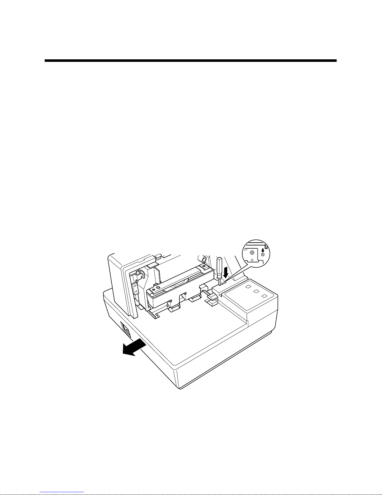
Accessing the DIP switches
The DIP switches are located inside the printer, underneath the document table.
Use the following procedure to remove the document table so you can operate
the DIP switches.
❏
Make sure that the printer is turned off and unplugged from its wall outlet.
❏
Remove the printer cover.
❏
While using a screwdriver or other similar instrument to press down at the
location marked (a) in the illustration below, carefully slide the document
table in the direction indicated by the arrow until it is out of the way.
a
Page 5
2
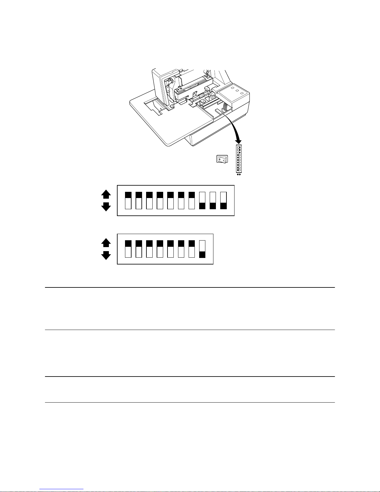
It is not necessary to remove the document table completely, just move it
enough so you can get at the DIP switches inside.
Note:
If the document table seems to be getting caught on the rollers, it means that
you are not pressing down at point (a) enough. Pressing at point (a) should
separate the rollers to the document table can slide freely.
❏
After the document table is opened sufficiently, use a thin flat-blade
screwdriver or some other similar object to change DIP switch settings.
Note:
See the following section for details on available DIP switch settings.
❏
After making the settings you want, slide the document table back into
place while pressing down at point (a). Make sure that the document table
is correctly seated in place before releasing point (a).
❏
Replace the printer cover.
ON
OFF
ON
OFF
12345678
(For Serial Interface)
(For Parallel Interface)
ON
OFF
12345678910
Page 6
3
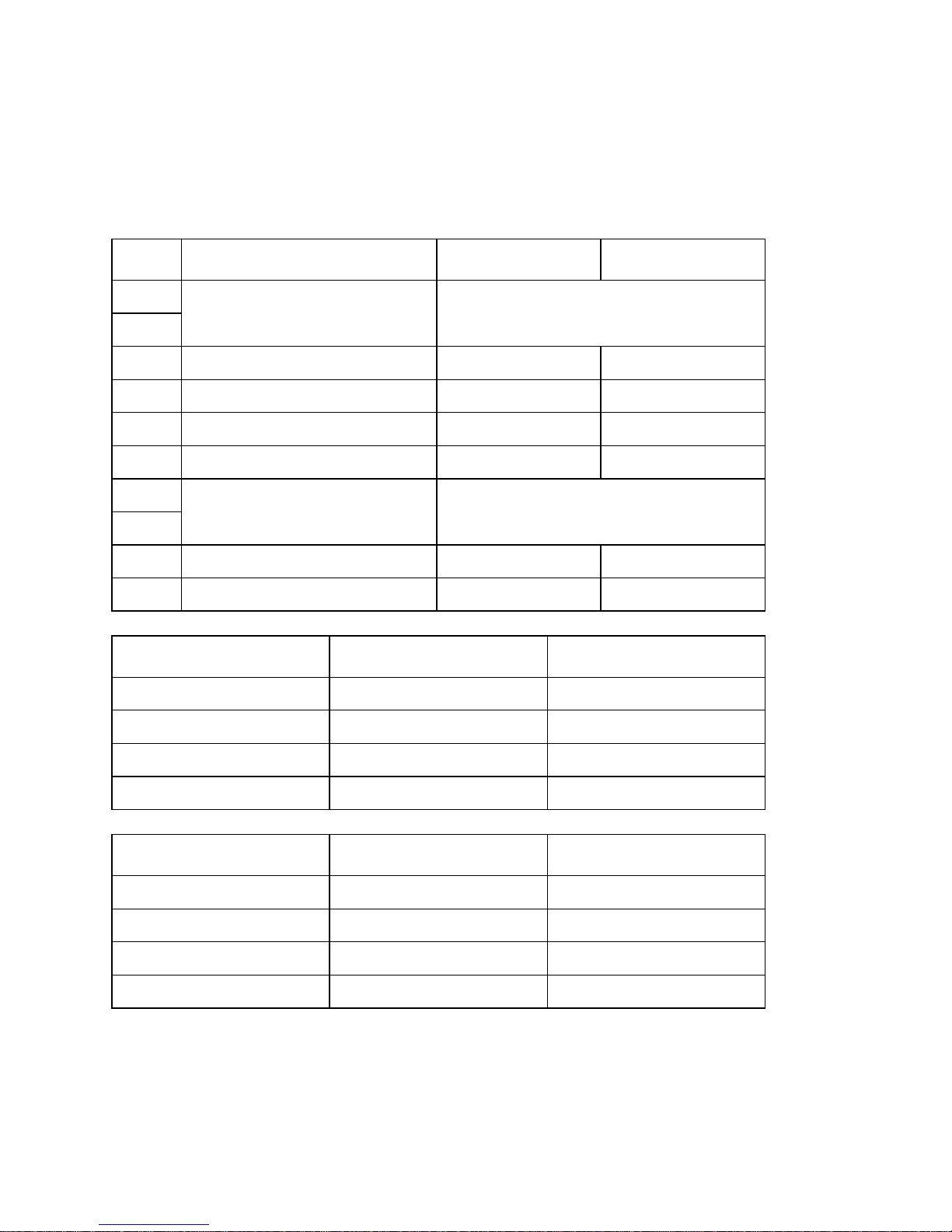
Available DIP switch settings (Serial Interface)
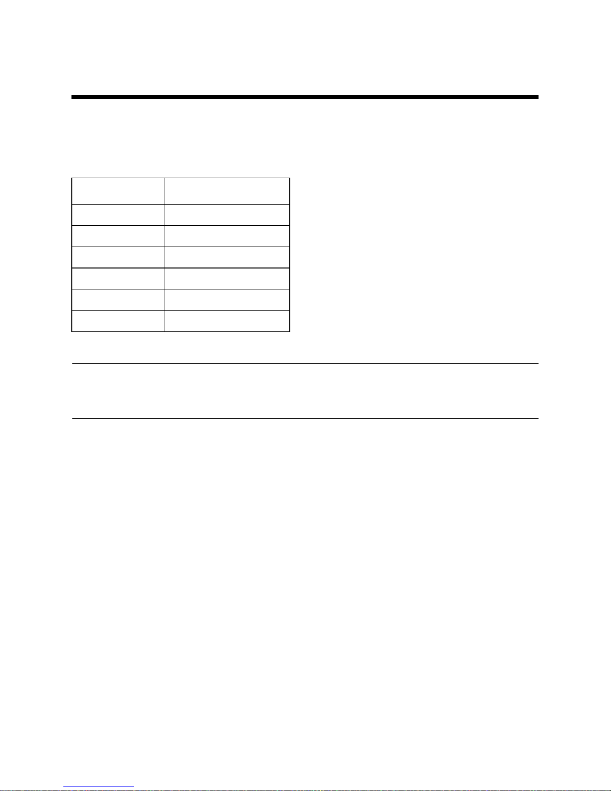
The following table shows all the possible settings for the DIP switch. The
factory default settings are ON for switches 1 through 7 and OFF for switches
8 through 10.
*1: Never set switch 7 to OFF at the same time that switch 8 is set to ON.
Switch Parameter ON OFF
1
Baud Rate See table below.
2
3 Data Length 8 bits 7 bits
4 Parity Check Disabled Enabled
5 Parity Odd Even
6 Handshake DTR/DSR XON/XOFF
7
Command Emulation See table below.
8
9 Pin 6 (DSR) Reset Signal Enabled Disabled
10 Pin 25 (INIT) Reset Signal Enabled Disabled
Baud Rate Switch 1 Switch 2
1200BPS OFF OFF
2400BPS ON OFF
4800BPS OFF ON
9600BPS ON ON
Command Emulation Switch 7 Switch 8
Star mode ON ON
ESC/POS (TM-295) ON OFF
ESC/POS (TM-290) OFF OFF
Not used (*1) OFF ON
Page 7
4
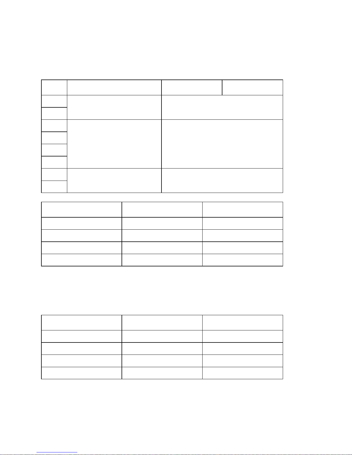
Available DIP switch settings (Parallel Interface)
The following table shows all the possible settings for the DIP switch. The
factory default settings are ON for switches 1 through 7 and OFF for switch 8.
A reset can be performed with pin 31 on the interface by setting DIP switch 1 to
ON (the factory default setting).
In addition, when a reset can be performed with pin 31, setting DIP switch 2 to
OFF sets up the unit to perform a reset when pin 31 and pin 36 are “LOW”.
*1: Never set switch 7 to OFF at the same time that switch 8 is set to ON.
Switch Parameter ON OFF
1
Pin 31 / Pin 36 Reset Signal See table below.
2
3
Not used (Always ON)
4
5
6
7
Command Emulation See table below.
8
Reset Signal Switch 1 Switch 2
Pin 31 is enabled. ON ON
Pin 31/Pin 36 are enabled. ON OFF
Disabled OFF ON
Disabled OFF OFF
Command Emulation Switch 7 Switch 8
Star mode ON ON
ESC/POS (TM-295) ON OFF
ESC/POS (TM-290) OFF OFF
Not used (*1) OFF ON
Page 8
5
Chapter 2: Memory Switch Settings
Each memory switch is a 16-bit word store in EEPROM. For details on the
functions and settings of memory switches, refer to “Chapter 6”.
The table below shows the factory settings for the memory switches.
Warning!
Changing the memory switch settings can cause the printer to fail to operate
correctly.
Memory Switch Hexadecimal Code
0 0000
1 0000
2 0000
3 0000
4 0000
5 0000
Page 9
6
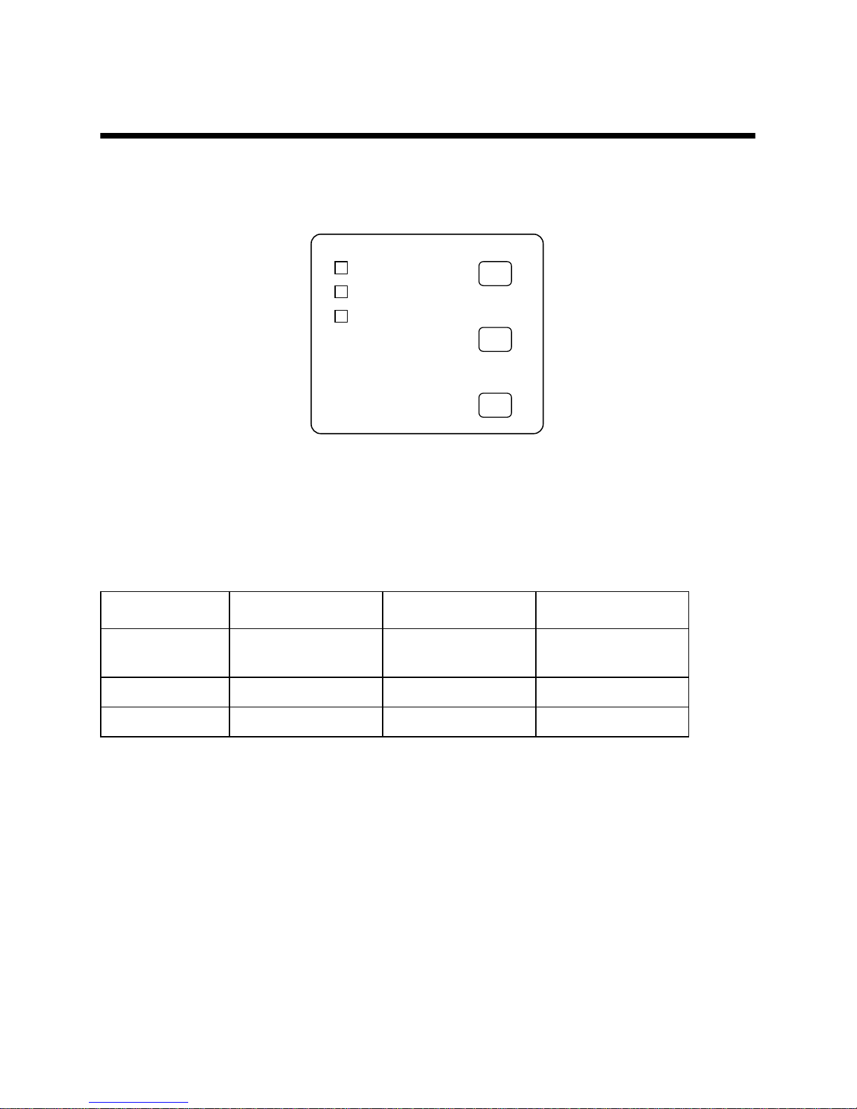
Chapter 3: Control Panel Operations
The control panel gives you some push-button control over the slip printer
operation. It also includes indicator lights, which tell you the current status of
the printer at a glance.
Indicator lights
The following table describes the meaning of indicator lights when it is on, off,
or flashing.
Indicator Light Off On Flashing
POWER
Power off Power on
Dot Alignment Adjust
Mode
PAPER OUT
Paper inserted No paper Insert paper prompt
RELEASE
Slip paper engaged Slip paper released Mechanical error
FORWARD
POWER
RELEASE
PAPER
OUT
REVERSE
RELEASE
Page 10
7
Buttons
The following table describes the function of the three control buttons of the
control panel.
Producing a test print
The following procedure can be used at any time to test the printer.
❏
Turn on the printer and insert a piece of paper (page 6, 11).
❏
Turn off printer power.
❏
While holding down RELEASE , turn printer back on. Keep RELEASE
depressed for a few moments until the printer beeps and the printer test
print starts.
The printer test will continue until it reaches the end of the paper.
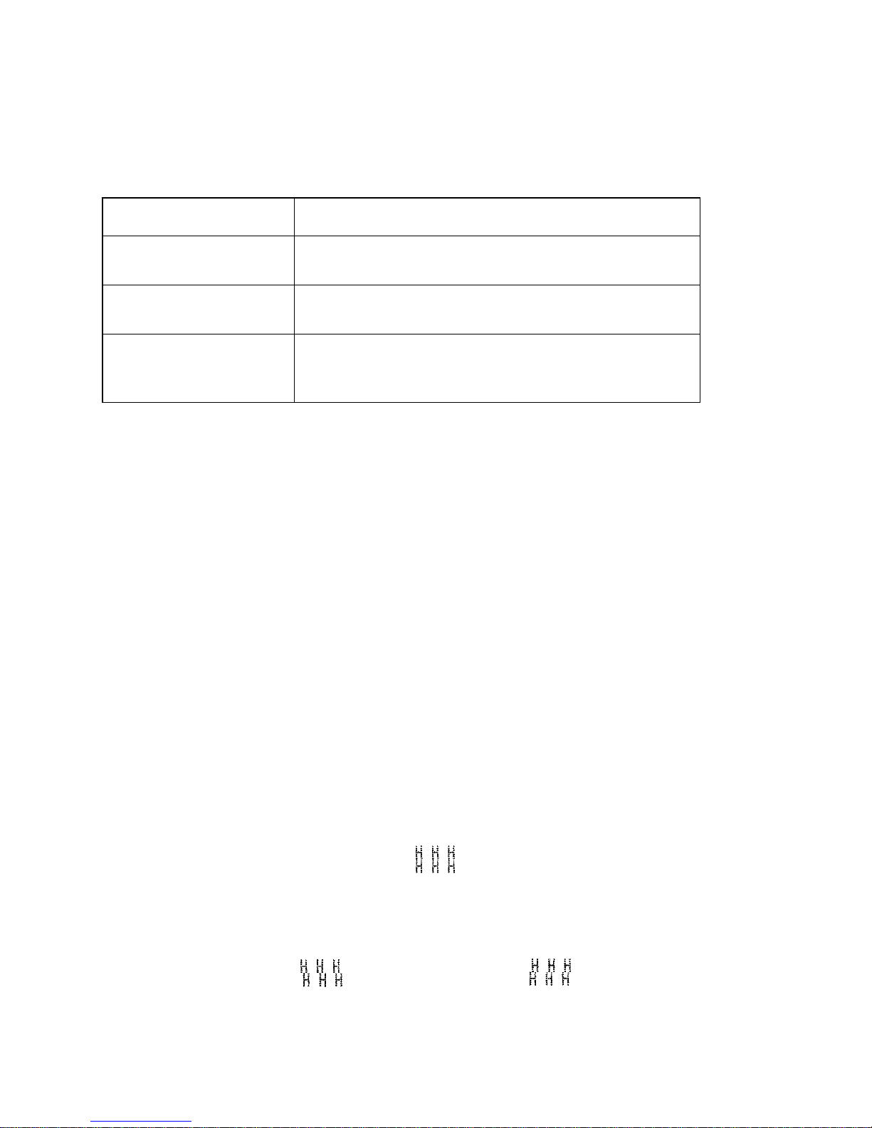
Adjusting the dot alignment
You may never have to use the procedure described in this section, but after you
have been using your printer for some time you may find that the dots of some
graphics do not align correctly. For example, what should look like:
may come out looking like one of the following:
Button Description
FORWARD
Feeds the slip paper forward, toward the back of the printer. One press
feeds one line, holding down performs continuous feed.
REVERSE
Feeds the slip paper back, toward the front of the printer. One press
feeds one line, holding down performs continuous feed.
RELEASE
Activates the printer's paper release (the paper is not held in place by
the paper feed roller).
Clears recoverable errors.
or like this
Page 11
8
This is caused when mechanical parts of the printer get out of alignment. This
happens only rarely and you may never experience it at all throughout the life
of the printer. If you do have problems, use the following procedure to correct it.
❏
Turn on the printer and insert a piece of paper.
❏
Turn off printer power.
❏
While holding down the control panel’s FORWARD and REVERSE
buttons, turn the printer back on to enter the Dot Alignment Adjust Mode,
which is indicator by a flashing POWER indicator flashes.
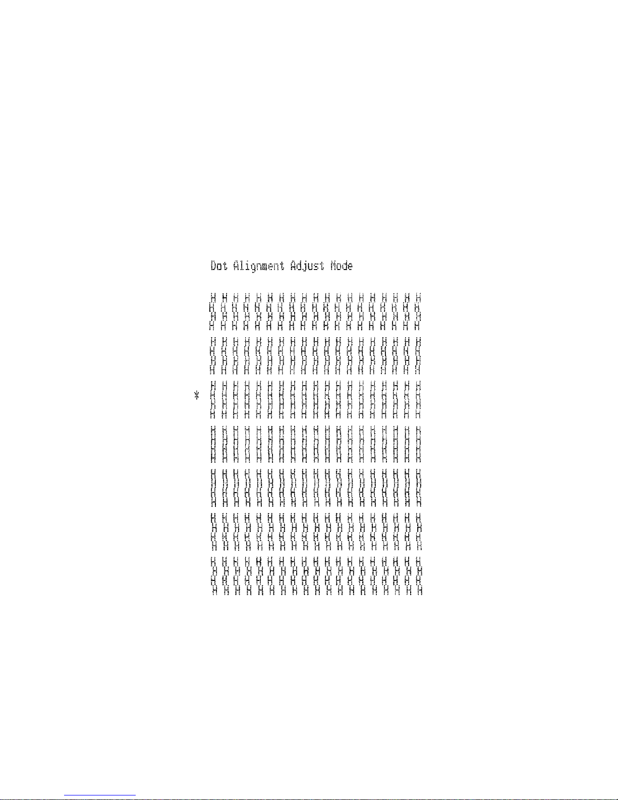
Entering the Dot Alignment Adjust Mode causes seven blocks to be printed,
each of which indicates a dot alignment setting, as shown below. An asterisk
to the left of the blocks indicates which block is currently selected.
❏
Use FORWARD to specify the block that appears to have the best aligned
characters. Press FORWARD once to specify the first block, twice to
specify the second block, and so on up to seven times to specify the se v enth
block.
Warning beep will sound if you press FORWARD more than seven times.
❏
After specifying a block, press REVERSE to register your selection and
exit the Dot Alignment Adjust Mode.
Page 12
9
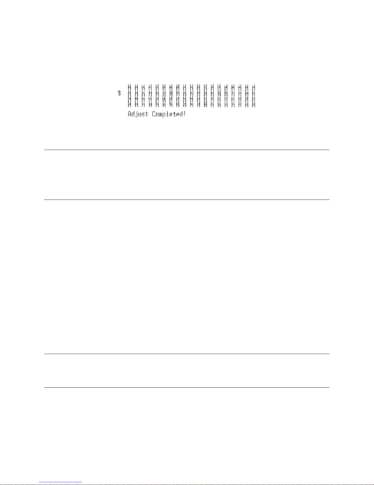
The dots alignment adjustment setting you selected is stored in printer memory
and a pattern is printed using the selected setting followed by the message
“Adjust Complete!” The printer ejects the paper after printing is complete.
Note:
You setting is not registered if you turn off printer power before pressing
REVERSE to exit the Dot Alignment Adjust Mode.
If a paper feed error occurs during this mode, the printer ejects the paper and
this mode is cancelled.
Hexadecimal dump
This procedure prints in hexadecimal format all codes (character codes and
control codes) that are sent to the printer by the computer. The printer does not
execute any control codes (such as 0A - linefeed), it just prints them out. The
hexadecimal dump is useful when you are writing programs for printer control.
❏
Turn on the printer and insert a piece of paper.
❏
Turn off printer power.
❏
While holding down the control panel’s FORWARD buttons, turn the
printer back on to enter the Hex Dump Mode.
❏
To exit the Hex Dump Mode, turn the printer off.
Note:
The printer will not responde to any commands you send it while it is in the
Hex Dump Mode.
Page 13
10
Errors
There are three types of errors: recoverable errors that require some action by
you before they clear, non-recoverable errors that require servicing by an
authorized service provider, and a data receive error. Errors are indicated by and
audible buzzer and the indicators.
Recoverable Errors
Non-recoverable Errors
Data Receive Error
This type of error is caused whenever a problem is encountered during data
receipt. The method used by the printer to recover from a data receive error
depends on the current command mode.
Error Type
Indicators
Recovery
POWER RELEASE PAPER OUT
Paper jam
Flashing
Correct the cause of the problem and
then press RELEASE.
Carriage motor lockup
Abnormal home position signal
Abnormal timing signal
Error Type
Indicators
Recovery
POWER RELEASE PAPER OUT
RAM read/write
Off On On
Turn off the printer, then after waiting a
few minutes, turn the printer back on. If
the printer does not recover, contact
your nearest service provider.
CPU lockup
Command mode Data Receive Error Recover Procedure
Star mode The printer prints a question mark.
ESC/POS mode
Memory switch 4-0=0 : The printer prints a question mark.
Memory switch 4-0=1 : The printer discards the received data.
Page 14
11
Chapter 4: Interface0
Serial Interface
❏
This chapter provides detailed specifications for the printer’ s standard serial
interface (Connector Type: D-sub 25-pin).
Set the transmission parameters with DIP Switch.
Transmission type............Asynchronous serial interface
Baud rate (bps).................1200, 2400, 4800 or 9600
(Selected by DIP switch)
Word format
Start bit:................1
Data bits: ..............7 or 8 (Selected by DIP switch)
Parity:...................Odd, Even, or None
(Selected by DIP switch)
Stop bit:................1
Signal polarities
RS-232C...............Mark = Logic “1” (–3V to –15V)
Space = Logic “0” (+3V to +15V)
Handshaking ....................DTR/DSR or XON/XOFF mode (Selected by DIP
switch)
Input (RXD, DSR, INIT)
Output (DTR, TXD, RTS)
b0 b1 b2 b3 b4 b5 b6 (b7)
ABCD
Mark [1]
Space [0]
A: Start bit
B: Data bits
C: Vertical parity bit
D: Stop bit
Printer Host computer
75188 or equivalent
Printer Host computer
Page 15
12
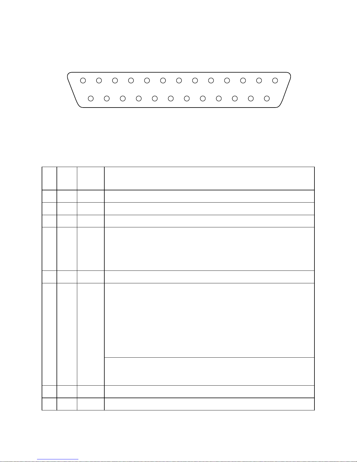
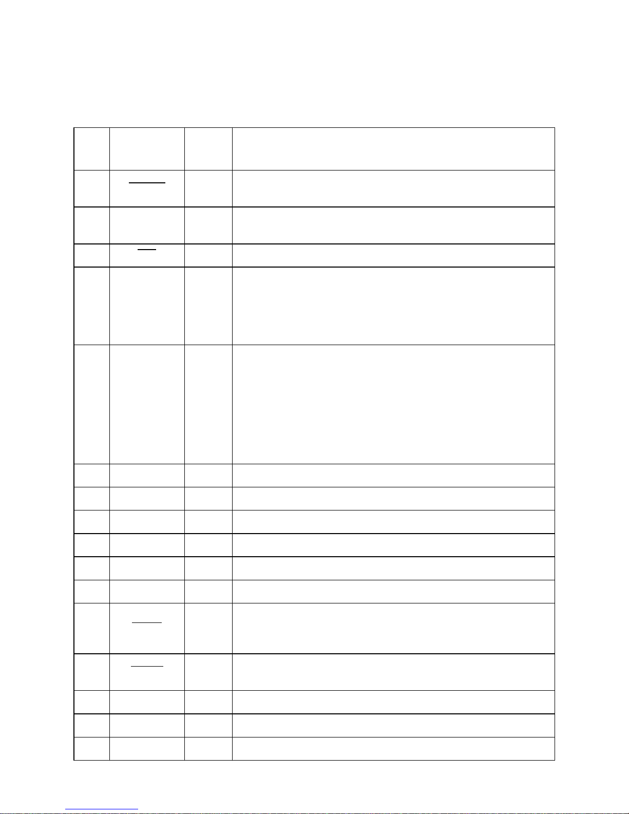
Serial interface pins and signal names
Pins and Signal Names
Pin
No.
Signal
Name
Direction Function
1 FG — Frame ground
2 TXD OUT Transmission data
3 RXD IN Receive data
4 RTS OUT
STAR Mode
When Memory Switch 4-D = 0: Same as DTR signal
When Memory Switch 4-D = 1: Always SPACE
ESC/POS Mode
Same as DTR signal
5 N.C. Not connected
6 DSR IN • DIP Switch 9 = OFF
STAR Mode
Status of this signal is not checked.
ESC/POS Mode
In DTR/DSR communication mode when Memory Switch4-5 = 0, indicates whether data
receive from host is enabled or disabled.
Space: Receive enabled
Mark: Receive disabled
This signal is not checked in the X-ON/X-OFF communication mode.
• DIP Switch 9 = ON
This signal used for external reset. Printer is reset whenever signal is in mark state with
pulse width of 1mS or more.
7 SG Signal ground
8 - 1 9 N.C. Not connected
13
25
1
14
Page 16
13
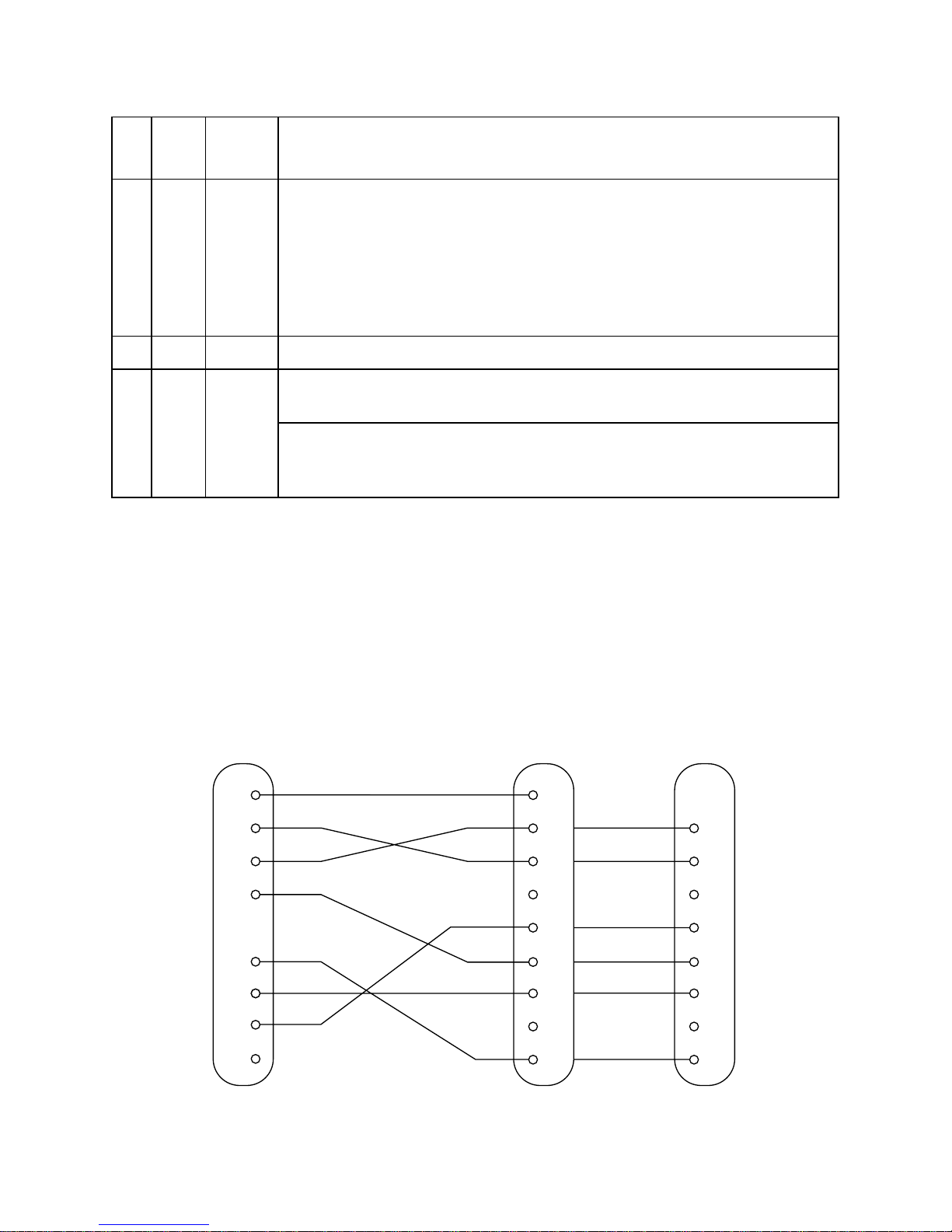
Interface connections
❏
Refer to the interface specifications for the host computer for details on
connecting to its interface connector. The following illustration shows a
typical connection configuration.
20 DTR OUT Indicates whether data receive from host is enabled or disabled.
DTR/DSR Communication Mode
Space when receive is enabled.
X-On/X-Off Communication Mode
Always space, except during following conditions:
• Period between reset and communication enabled
• During self-test printing and dot alignment adjustment
2 1 - 2 4 N.C. Not connected
25 INIT IN • DIP Switch 10 = OFF
This signal not used.
• DIP Switch 10 = ON
This signal becomes reset signal. Printer is reset whenever signal is in mark state with pulse
width of 1mS or more.
Pin
No.
Signal
Name
Direction Function
1
2
3
4
6
1
2
3
4
5
6
7
8
20
F-GND
TXD
RXD
RTS
DSR
20
25
7
S-GND
DTR
INIT
Printer side
(D-sub 25 pin)
IBM PC side
3
2
7
8
6
5
1
4
F-GND
TXD
RXD
RTS
CTS
DSR
S-GND
DCD
DTR
9 pin25 pin
Page 17
14
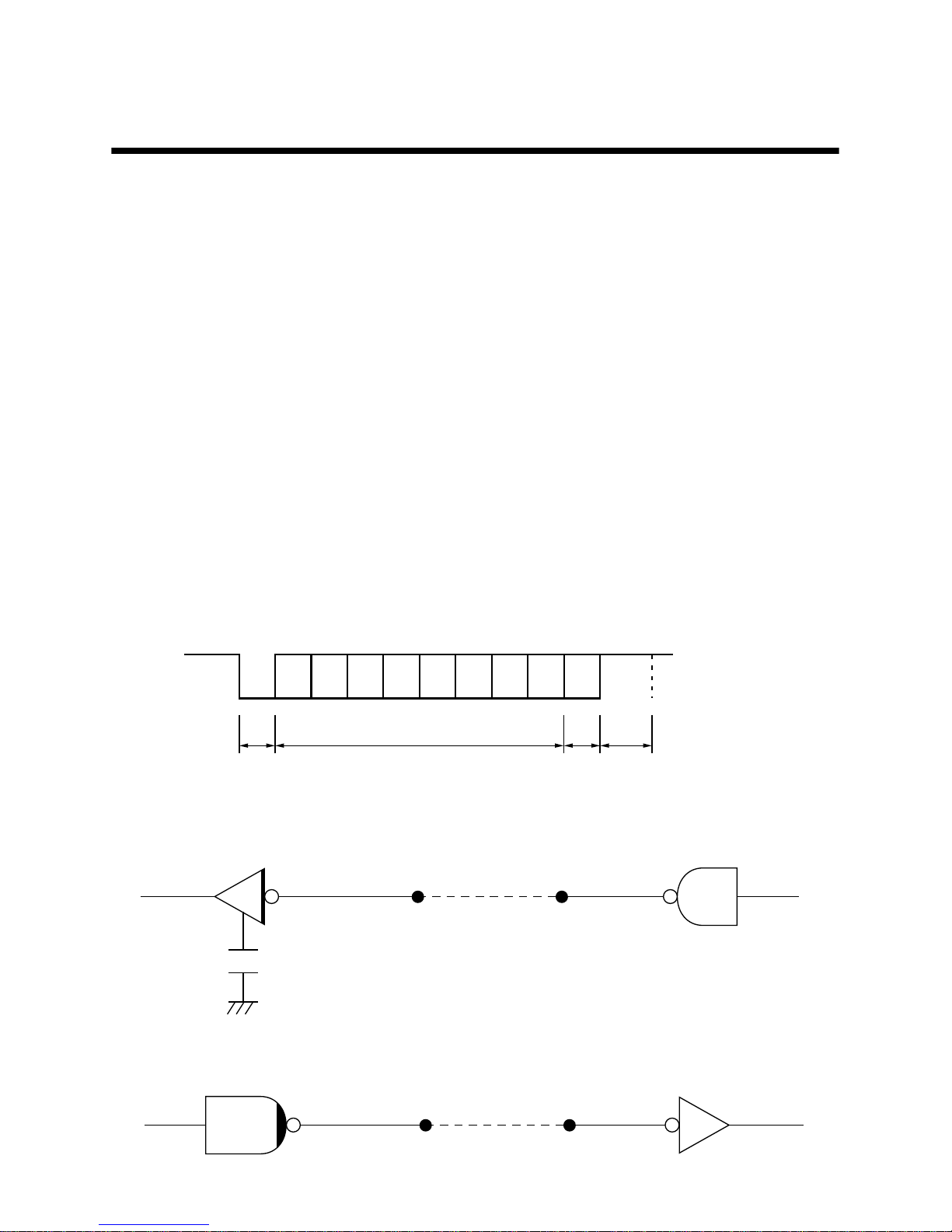
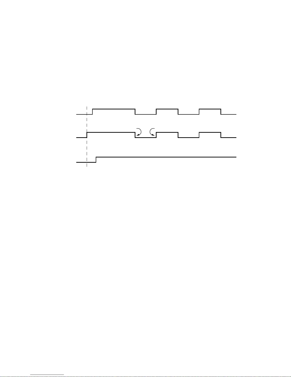
Data protocol
❏
Outline of DTR/DSR mode operations
This communication mode is set when dip switches 1 to 6 are set at ON.
The DTR signal shakes hands with the DSR signal (DSR signal: ESC/POS
mode only) and performs communications. The DTR signal is assumed as the
BUSY signal and then the control for the printer’s data receiving operations
are carreied out, and a “space” means that the printer is to receive the data, and
a “mark” means that the printer is not to receive the data.
The DTR signal line is set a “space” when the power supply is switched on and
no error occurs with the printer. The host confirms that the DTR signal line is
set at “space”, and then transmits the text data to the RXD signal line.
The printer sets the DTR signal line at “mark” when the empty area in the data
buffer is less that the prescribed number of bytes (*1: nearly full buffer
condition.) The host confirms that the DTR signal line is set at “mark” and
suspends text data transmission, but it is possible for the printer to continue
receiving data for the amount of space remaining in the data buffer’s empty area
at this point. If the DTR signal is ignored and data transmitted, the data that
exceeds the amount of space available in the empty area will be discarded. The
empty area in the data buffer will increase as printing is carried out, and the
DTR signal line will be set at “space” if the amount of empty space in the data
buffer is more than the prescribed number of bytes (*2: near empty condition.)
In addition to this, the host will confirm that receiving is possible (DSR signal
= “space”) and transmit the data only when memory switches 4 and 5 are set
at 0 during printer status transmission in the ESC/POS mode’s DTR/DSR
communication mode. (With the exception of certain status transmission
commands. Also, dip switches 1 to 9 must be at OFF when the DSR signal is
confirmed.)
*1 Refer to the nearly full buffer conditions for details on nearly full buffer conditions.
*2 Refer to the nearly empty buffer conditions for details on nearly empty buffer
conditions.
RXD
DTR
Data Data Data
Buffer full Buffer empty
Printing
Power ON
Page 18
15
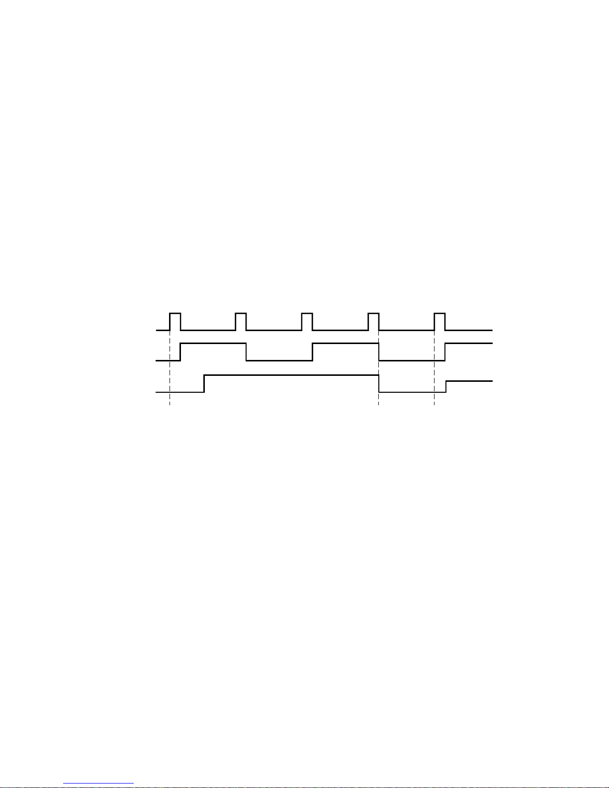
❏ Outline of X-ON/X-OFF mode operations
This communication mode is set when dip switches 1 to 6 are set at OFF.
This mode notifies the host of X-0N (DC1) data when receiving is possible
and X-OFF (DC3) data when printing is not possible with the TXD signal.
The timing conditions for the output of X-ON and X-ON in the STAR mode
are set with the 4-C memory switch. When memory switch 4-C = 0 (set when
the unit is shipped from the factory,) only one byte is output by X-ON during
fluctuations from on-line (printer BUSY) to on-line (printer READY), and
only one byte is output by X-OFF during fluctuations from on-line (printer
READY) to on-line (printer BUSY). The same functions as above occur when
in the ESC/POS mode regardless of the 4-C memory switch setting.
When memory switch 4-C = 1, X-ON is output at regular three-second
intervals.
X-ON (DC1 with the control code name and 11H with hexadecimal display)
is output by the TXD signal line when the power supply is switched on and no
error occurs with the printer. The text data is transmitted to the RSD signal line
after the host has received X-ON.
X-OFF (DC3, 13H) is output when the empty area in the data buffer is less that
the prescribed number of bytes (*1: nearly full buffer condition.) Also, if
memory switch 4-C = 1, X-OFF is output for every byte of data received. The
host that receives X-OFF suspends text data transmission, but it is possible for
the printer to continue receiving data for the amount of space remaining in the
data buffer’s empty area at this point. If data that exceeds the amount of space
available in the empty area is transmitted, it will be discarded.
The empty area in the data buffer will increase as printing is carried out, and X-
ON is output if the amount of empty space in the data buffer is more than the
prescribed number of bytes (*2: near empty condition.)
*1 Refer to the nearly full buffer conditions for details on nearly full buffer conditions.
*2 Refer to the nearly empty buffer conditions for details on nearly empty buffer
conditions.
TXD
RXD
X–ON X–OFF X–ON X–OFF X–ON
Printing
Data Data Data
Page 19
16
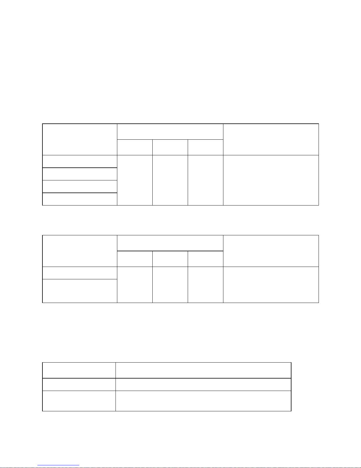
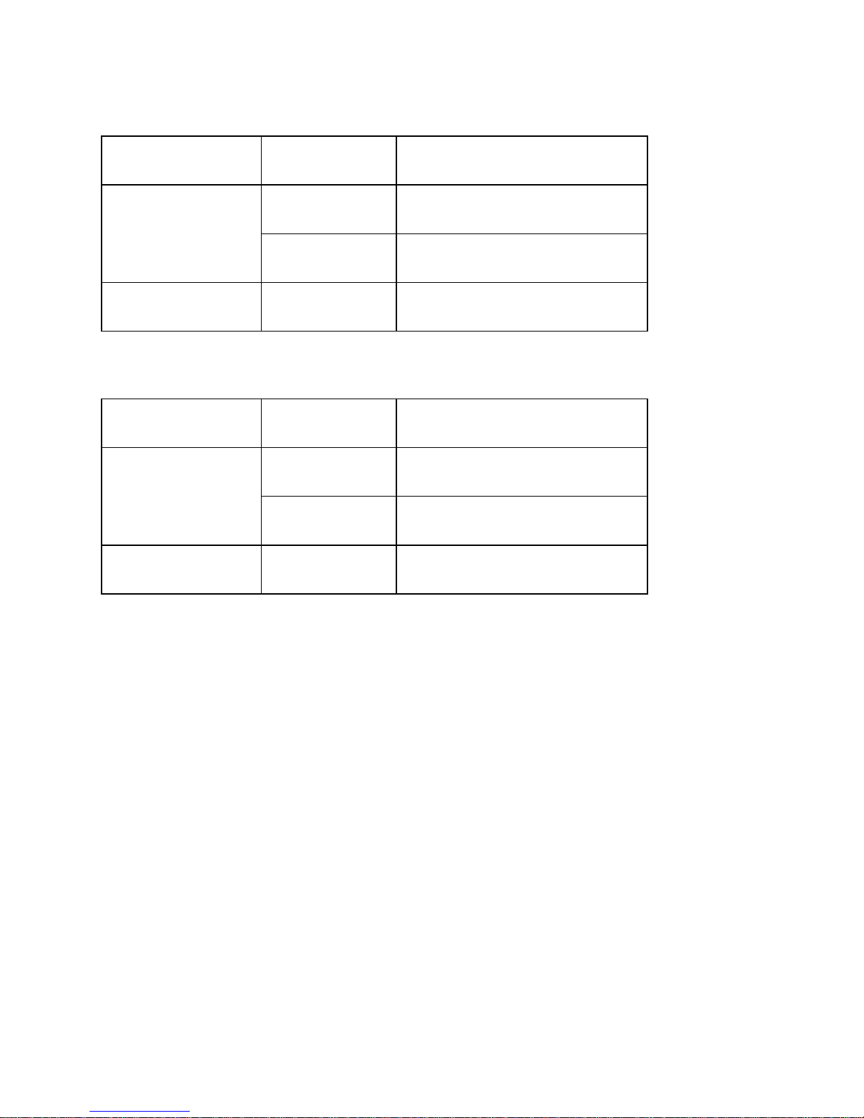
Nearly full buffer conditions
Nearly empty buffer conditions
Emulation
(DSW8)
Buffer size
(DSW7)
Available area
(during fluctuations)
STAR mode
2K byte
When 256 bytes or less are
available
35 byte
When 16 bytes or less are
available
ESC/POS mode 512/35 bytes
When 10 bytes or more are
available
Emulation
(DSW8)
Buffer size
(DSW7)
Available area
(during fluctuations)
STAR mode
2K byte
When 1792 bytes or less are
available
35 byte
When 20 bytes or less are
available
ESC/POS mode 512/35 bytes
When 20 bytes or more are
available
Page 20
17
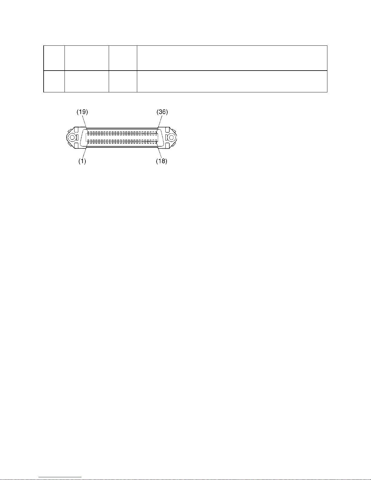
Parallel Interface
Connectors and Signals
Pin
No.
Signal Name IN/OUT Function
1 STROBE IN
Signals when data is ready to be read. Signal goes from HIGH to LOW (for at
least 0.5 microsec.) when the data is available.
2-9 DATA1-8 IN
These signals provide the information of the first to eighth bits of parallel data.
Each signal is at HIGH level for a logical 1 and at a LOW level for a logical 0.
10 ACK OUT A 9 microsecond LOW pulse acknowledges receipt of the data.
11 BUSY OUT
When this signal goes to LOW, the printer is ready to accept data. When the
printer is in one of the conditions below, “HIGH” is set.
1. Data is being entered
2. Off line
3. Error condition
12 PAPER OUT OUT
This signal indicates the status of the paper sensor.
[In Star mode]
This signal goes to HIGH when either the TOF or the BOF sensor detects that
there is no paper. The signal will go to LOW when both the TOF and BOF
sensor detect that there is paper installed.
[In the ESC/POS mode]
This signal outputs the status of the sensor selected using the <ESC> “c3”
command.
13 SELECTED OUT This signal is HIGH when the printer is online.
14-15 N/C Unused
16 SIGNAL GND Signal ground
17 CHASSIS GND Chassis ground, isolated from logic ground
18 LOGIC HIGH 3.9 k
Ω
pull-up
19-30 GND Twisted pair return the signal to ground level.
31 RESET IN
This becomes a reset signal when DIP switch 1 is set to ON. (See page 4 for
details.) When this signal goes to LOW (for at least 0.5 microsec.), the printer is
reset to its power-on condition.
32 ERROR OUT
This signal is normally HIGH. This signal goes to LOW to signal that the printer
cannot print due to an error condition.
33 EXT GND External ground
34 COMPULSION OUT Compulsion signal (See page 20.)
35 +5VDC 2.2 kΩ pull-up
Page 21
18
36 SELECT IN IN
Unused (However, this becomes a reset signal when DIP switch 1 is set to ON
and DIP switch 2 is set to OFF. See page 4 for details.)
Pin
No.
Signal Name IN/OUT Function
This connector mates with an Amphenol
57-30360 connector
Parallel interface connector (printer side)
Page 22
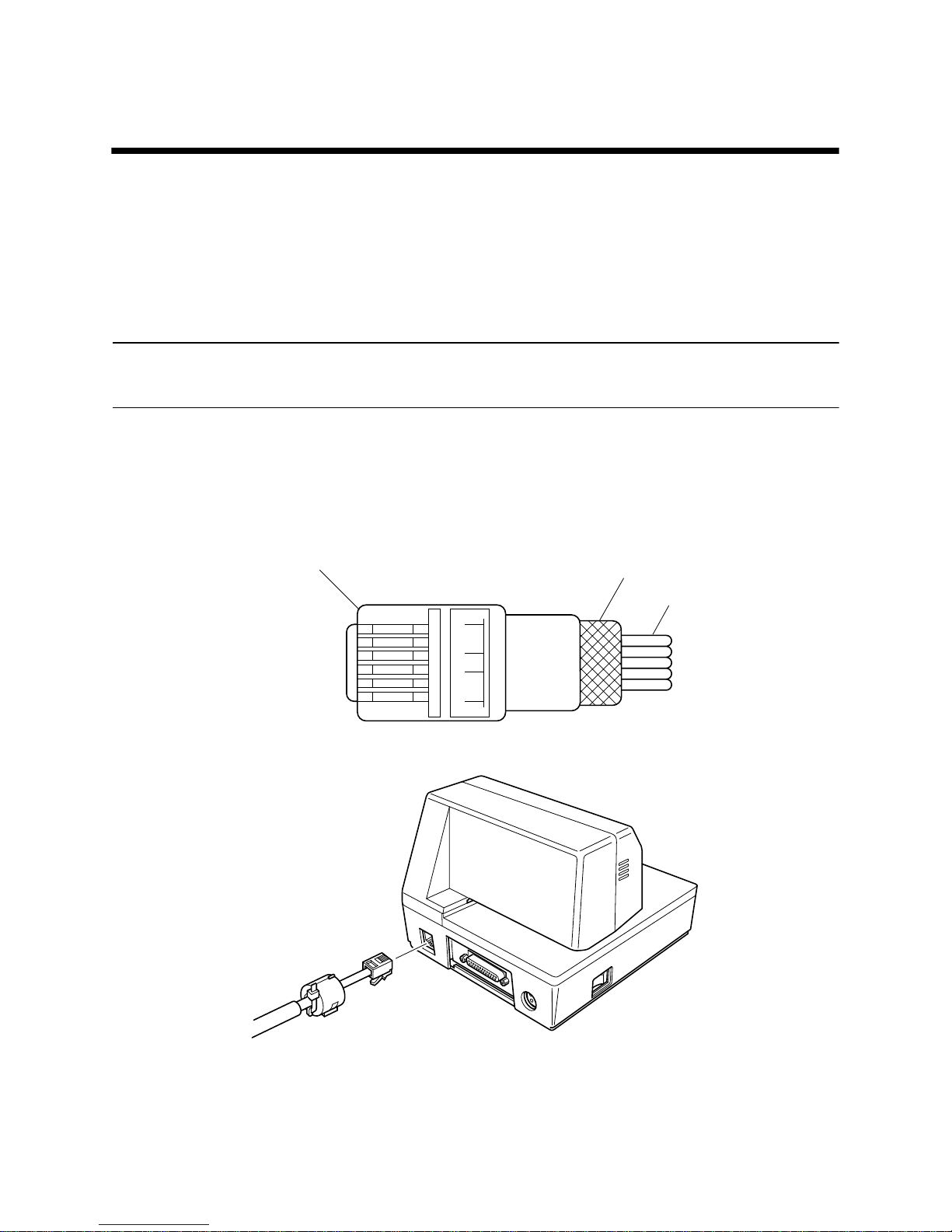
19
Chapter 5: Peripheral Unit Driver Circuit
This printer is equipped with a circuit for driving peripheral units, such as cash
drawers. A 6-pin modular connector for connection of the peripheral unit is
located on the back of the printer. To connect to the drive circuit, connect the
peripheral unit to the modular connector using a cable supplied by you like that
one shown in the figure below.
Important!
Never connect any other type of plug to the peripheral unit connector.
Modular plug
16
Modular plug: MOLEX 90075-0007,
AMP641337, or JAPAN BURNDY B-66-4
Shield
Wire lead
Page 23
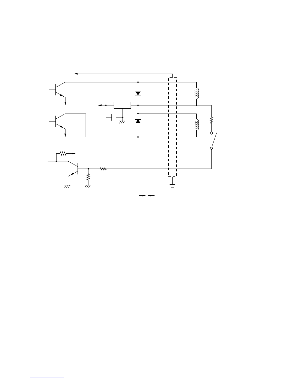
20
Drive circuit
The recommended drive unit is shown below.
Notes
• Peripheral Units 1 and 2 cannot be driven simultaneously.
• For continuous driving, do not use drive duty greater than 20%.
• When using a serial interface, the compulsion switch status is available
as status data. When using a parallel interface, the compulsion switch
status can be worked out from the position of the number 34 pin of the
interface connector . The switch status is ON when the number 34 pin is at
LOW level.
• Minimum resistance for coils L1 and L2 is 24Ω.
• Absolute maximum ratings for diodes D1 and D2 (Ta = 25°C) are:
Average Rectified Current Io = 1A
Maximum forward surge current (60Hz, 1-cycle sine wave) I
FSM
= 40A
• Absolute maximum rating for transistors TR1 and TR2 (Ta = 25°C) are:
Collector current Ic = 2A
Collector loss Pc = 1.2W
7824
F.G
TR1
M-GND
TR2
M-GND
TR3
+5V
+24V
R1
R2
6
5
4
3
2
1
L1
L2
R3
4.7kΩ
1/4W
Frame
ground
Printer side User side
D1
D2
Peripheral
unit 1
With shield
Peripheral
unit 2
Compulsion
switch
Drive output: 24V, 1.0A max.
Page 24
21
Chapter 6: Control Codes
This printer supports two different command modes: the Star mode and the
ESC/POS mode.
The Star mode emulates previous Star printers. The ESC/POS mode emulates
the Epson TM-295 or TM-290 slip printer.
This chapter provides you with all of the commands supported by this printer.
Important!
Access the following URL for the latest version of this manual and for updates
on supported commands: http://www.star-micronics.co.jp/service/
sp_sup_e.htm
Star Mode Commands
The following tables show the Star mode commands that are supported by this
printer.
Character Selection
Control Codes
Hexadecimal
Codes
Function Page
<ESC> “R”
n
1B 52
n
Selects the international character set 30
<ESC> “/” “1”
<ESC> “/” <1>
1B 2F 31
1B 2F 01
Selects slash zero 30
<ESC> “/” “0”
<ESC> “/” <0>
1B 2F 30
1B 2F 00
Selects normal zero 30
<ESC> <GS> “t”
n
1B 1D 74
n
Selects the character code table 30
<ESC> “M” 1B 4D Selects the 7 × 9 (half dot) font 31
<ESC> “P” 1B 50 Selects the 5 × 9 (2 pulses per dot) font 31
<ESC> “:” 1B 3A Selects the 5 × 9 (3 pulses per dot) font 31
<ESC> <SP>
n
1B 20
n
Sets character spacing 31
<SO> 0E Sets the printing magnified double in character width 31
<DC4> 14 Resets the printing magnified in character width 31
Page 25

22
<ESC> “W”
n
1B 57
n
Sets the magnification rate in character width 32
<ESC> “h”
n
1B 68
n
Sets the magnification rate in character height 32
<ESC> “–” “1”
<ESC> “–” <1>
1B 2D 31
1B 2D 01
Selects underlining 32
<ESC> “–” “0”
<ESC> “–” <0>
1B 2D 30
1B 2D 00
Cancels underlining 32
<ESC> “_” “1”
<ESC> “_” <1>
1B 5F 31
1B 5F 01
Selects upperlining 32
<ESC> “_” “0”
<ESC> “_” <0>
1B 5F 30
1B 5F 00
Cancels upperlining 32
<ESC> “4” 1B 34 Selects highlight printing 33
<ESC> “5” 1B 35 Cancels unhighlight printing 33
<SI> 0F Inverted printing 33
<DC2> 12 Cancels inverted printing 33
<ESC> <RS> “i” “0”
<ESC> <RS> “i” <0>
1B 1E 96 30
1B 1E 96 00
Cancels rotated print mode for text (Default) 33
<ESC> <RS> “i” “1”
<ESC> <RS> “i” <1>
1B 1E 96 31
1B 1E 96 01
Specifies rotated print mode for text with a 270˚ rotation. 33
<ESC> <RS> “i” “2”
<ESC> <RS> “i” <2>
1B 1E 96 32
1B 1E 96 02
Specifies rotated print mode for text with a 90˚ rotation. 33
<ESC> “E” 1B 45 Selects emphasized printing 34
<ESC> “F” 1B 46 Cancels emphasized printing 34
<ESC> “U”
n
1B 55
n
Selects print direction 34
Control Codes
Hexadecimal
Codes
Function Page
Page 26

23
Print Position Control
Control Codes
Hexadecimal
Codes
Function Page
<LF> 0A Line feed 35
<CR> 0D Carriage Return 35
<ESC> “a”
n
1B 61 n
Feeds paper n lines 35
<HT> 09 Horizontal tab 35
<ESC> “A”
n
1B 41
n
Defines n/72-inch line spacing 35
<ESC> “2” 1B 32 Sets n/72-inch line spacing 36
<ESC> “z” “0”
<ESC> “z” <0>
1B 7A 30
1B 7A 00
Sets line spacing to 1/12-inch 36
<ESC> “z” “1”
<ESC> “z” <1>
1B 7A 31
1B 7A 01
Sets line spacing to 1/6-inch 36
<ESC> “0” 1B 30 Sets line spacing to 1/8-inch 36
<ESC> “1” 1B 31 Sets line spacing to 7/72-inch 36
<ESC> “J”
n
1B 4A
n
One time n/72-inch feed 37
<ESC> “j”
n
1B 6A
n
One time n/72-inch backfeed 37
<ESC> “3”
n
1B 33
n
Sets line spacing to n/216-inch approximately 37
<ESC> “y” 1B 79
n
Sets line spacing to n/144-inch 37
<ESC> “D”
n1 n
2 ...
<0>
1B 44
n1 n
2 ...
00 Sets horizontal tab stops 38
<ESC> “l”
n
1B 6C
n
Sets left margin 38
<ESC> “Q”
n
1B 51
n
Sets right margin 38
<ESC> <GS> “a” “0”
<ESC> <GS> “a” <0>
1B 1D 61 30
1B 1D 61 00
Left justification (Default) 39
<ESC> <GS> “a” “1”
<ESC> <GS> “a” <1>
1B 1D 61 31
1B 1D 61 01
Centering 39
<ESC> <GS> “a” “2”
<ESC> <GS> “a” <2>
1B 1D 61 32
1B 1D 61 02
Right justification 39
Page 27

24
Dot Graphics Control
Download Graphics Printing
Peripheral Device Control
Control Codes
Hexadecimal
Codes
Function Page
<ESC> “K”
n <0>
m1 m2 ...
1B 4B
n 00 m1 m
2
...
Prints normal density graphics 40
<ESC> “L”
n1 n
2
m1 m2 ...
1B 4C
n1 n2
m
1
m
2 ...
Prints high density graphics 42
Control Codes
Hexadecimal
Codes
Function Page
<ESC> “&” <0>
n1 n2
.. 1B 26 00
n1 n2
.. Defines download characters 43
<ESC> “%” “1”
<ESC> “%” <1>
1B 25 31
1B 25 01
Enables download character set 44
<ESC> “%” “0”
<ESC> “%” <0>
1B 25 30
1B 25 00
Disables download character set 44
Control Codes
Hexadecimal
Codes
Function Page
<ESC> <BEL>
n1 n2 1B 07 n1 n2
Defines drive pulse width for peripheral device #1 45
<BEL> 07 Controls peripheral device #1 45
<FS> 1C Controls peripheral device #1 immediately 45
<EM> 19 Controls peripheral device #2 immediately 45
<SUB> 1A Controls peripheral device #2 immediately 45
Page 28

25
Slip Control
Page mode
Other Commands
Control Codes
Hexadecimal
Codes
Function Page
<ESC> <SI>
n
1B 0F
n
Setting slip sensor 46
<ESC> <FF>
n
1B 0C
n
Slip function 46
<ESC> <VT>
m n
1B 0B
m n
Sets the paper eject direction/length 47
<EOT> 04 Slip status enquiry 47
<ESC> <EM>
m n
<LF> <NUL>
1B 19
n m
0A 00 Sets the wait time until the automatic clamp is activated 48
Control Codes
Hexadecimal
Codes
Function Page
<ESC> “n” 1B 6E Selects page mode 48
<ESC> “!” 1B 21 Selects line mode 50
<ESC> “*” ... 1B 2A ... Setting print area in page mode 50
<ESC> “T”
n
1B 54
n
Setting print direction in page mode 51
<FF> 0C Prints in page mode 53
Control Codes
Hexadecimal
Codes
Function Page
<CAN> 18 Cancels printer buffer & Initialize printer (imimediately) 54
<DC3> 13 Deselects printer 54
<DC1> 11 Sets select mode 54
<RS> 1E Beeps the buzzer 54
<ESC> “#N,
n1 n2 n
3
n4”
<LF> <NUL>
1B 23 N 2C
n1 n
2
n3 n
4
0A 00
Sets memory switch 55
<ESC> “@” 1B 40 Initialize printer 58
<ENQ> 05 Enquiry 58
<ESC> “?” <LF>
<NUL>
1B 3F 0A 00 Resets printer hardware and produces a test print 59
Page 29

26
ESC/POS Mode Commands (TM-295 emulation)
The following table lists the TM-295 mode commands that are supported by this
printer.
*1: n/60-inch line spacing and paper feed commands:
Since the minimum paper feed pitch for this printer is 1/144 inch, n/60 inch can
considered an approximate value. However, the actual value is INT ((6n/5) +
0.5)/72 inch.
Control Codes
Hexadecimal
Codes
Function
<HT> 09 Horizontal tab
<LF> 0A Line feed
<FF> 0C
Paper eject in single sheet mode
Paper mode print and return
<DLE> <EOT> 10 04 Enables real-time status send (Serial I/F only)
<CAN> 18 Cancels print data in page mode
<ESC> SP 1B 20 Sets size of space to right of character
<ESC> ! 1B 21 Enables batch print mode
<ESC># 1B 23 Sets memory switch
<ESC> % 1B 25 Enables/disables download character set
<ESC> & 1B 26 Defines download character
<ESC> * 1B 2A Selects bit image mode
<ESC> 2 1B 32 Selects 1/6-inch line spacing
<ESC> 3 1B 33 Selects approximate
n
/60-inch line spacing *1
<ESC> = 1B 3D Selects peripheral device
<ESC> @ 1B 40 Initializes the printer
<ESC> C 1B 43 Sets the eject length for single-sheet printing
<ESC> D 1B 44 Sets horizontal tab position
<ESC> F 1B 46 Enables/disables reverse feed for single-sheet mode
<ESC> J 1B 4A Prints and n/60-inch (approximate value) paper feed *1
<ESC> K 1B 4B
Prints and n/60-inch (approximate value) reverse paper feed
*1
Page 30

27
Control Codes
Hexadecimal
Codes
Function
<ESC> L 1B 4C Selects page mode
<ESC> R 1B 52 Selects international character set
<ESC> T 1B 54 Selects direction for page mode character printing
<ESC> U 1B 55 Selects print direction
<ESC> V 1B 56 Designates/cancels 90˚ character rotation
<ESC> W 1B 57 Sets print area for page mode printing
<ESC> a 1B 61 Aligns position
<ESC> c3 1B 63 33
Selects the paper-end sensor for sending the no-paper
signal
<ESC> c4 1B 63 34 Selects the paper-end sensor for stopping printing
<ESC> c5 1B 63 35 Enables/disables control panel switches
<ESC> d 1B 64 Prints or feeds
n
lines
<ESC> e 1B 65 Prints or reverse feeds n lines
<ESC> f 1B 66 Sets single-sheet wait time
<ESC> p 1B 70 Generates specified pulse
<ESC> q 1B 71 Release
<ESC> t 1B 74 Selects character code table
<ESC> u 1B 75 Sends peripheral status (Serial I/F only)
<ESC> v 1B 76 Sends paper sensor status (Serial I/F only)
<ESC> { 1B 7B Enables/disables inverted printing
<GS> I 1D 49 Sends printer ID (Serial I/F only)
<GS> a 1D 61
Enables/disables automatic send of printer status
(Serial I/F only)
<GS> r 1D 72 Sends printer status (Serial I/F only)
Page 31

28
ESC/POS Mode Commands (TM-290 emulation)
The following table lists the TM-290 emulation commands that are supported
by this printer.
*1: n/60-inch line spacing and paper feed commands:
Since the minimum paper feed pitch for this printer is 1/144 inch, n/60 inch can
considered an approximate value. However, the actual value is INT ((6n/5) +
0.5)/72 inch.
Control Codes
Hexadecimal
Codes
Function
<HT> 09 Horizontal tab
<LF> 0A Line feed
<FF> 0C Paper eject in single sheet mode
<ESC> SP 1B 20 Sets size of space to right of character
<ESC> ! 1B 21 Enables batch print mode
<ESC># 1B 23 Sets memory switch
<ESC> * 1B 2A Selects bit image mode
<ESC> 2 1B 32 Selects 1/6-inch line spacing
<ESC> 3 1B 33 Selects approximate n/60-inch line spacing *1
<ESC> @ 1B 40 Initializes the printer
<ESC> D 1B 44 Sets horizontal tab position
<ESC> M 1B 4D Selects the 7
×
9 font
<ESC> P 1B 50 Selects the 5 × 9 font
Page 32

29
Control Codes
Hexadecimal
Codes
Function
<ESC> R 1B 52 Selects international character set
<ESC> c3 1B 63 33
Selects the paper-end sensor for sending the no-paper
signal
<ESC> c4 1B 63 34 Selects the paper-end sensor for stopping printing
<ESC> c5 1B 63 35 Enables/disables control panel switches
<ESC> d 1B 64 Prints or feeds n lines
<ESC> h 1B 68 Sets/Cancels reverse line feed
<ESC> j 1B 6A Selects character width in vertical printing mode
<ESC> q 1B 71 Release
<ESC> t 1B 74 Selects character code table
<ESC> v
n
1B 76
n
Requests paper sensor status (Serial I/F only)
<ESC> { 1B 7B Enables/disables inverted printing
<FS> J 1C 4A Sets vertical printing mode
<FS> K 1C 4B Cancels vertical printing mode
<FS> W 1C 57 Sets/Cancels double-height, double-width printing
Page 33

30
Character Selection
<ESC> “R” n
1B 52 n
Selects international character set
Selects an international character set according to the value of n, as
shown below:
0 n 12, “0” n “9”, “A” n “C”
n = 0, “0” : U.S.A. 1, “1” : France 2, “2” : Germany
3, “3” : England 4, “4” : Denmark Ι 5, “5” : Sweden
6, “6” : Italy 7, “7” : Spain Ι 8, “8” : Japan
9, “9” : Norway 10, “A” : Denmark 2 11, “B” : Spain 2
12, “C” : Latin America
Although the international character set can also be selected using a
memory switch, the control code setting is given priority.
<ESC> “/” n
1B 2F n
Selects zero style
Causes subsequent zero characters to be printed with a slash when n
is 1, and without a slash when n is 0.
The valve of n can be set to 0(00H) or “0”(30H), or 1(0H) or
“1”(31H).
The default may differ depending on the memory switch setting.
<ESC> <GS> “t” n
1B 1D 74 n
Selects the character code table
This function selects a character code table (as shown below).
The default settings follow the settings of the memory switch.
The range of n is: 0 n 10
n = (00)H : Normal (01)H : code page 437
(02)H : katakana (03)H : code page 437
(04)H : code page 858 (05)H : code page 852
(06)H : code page 860 (07)H : code page 861
(08)H : code page 863 (09)H : code page 865
(0A)H : code page 866
CODE
HEX
FUNCTION
≤ ≤ ≤ ≤ ≤ ≤
CODE
HEX
FUNCTION
CODE
HEX
FUNCTION
≤ ≤
Page 34

31
<ESC> “M”
1B 4D
Selects 7 × 9 (half dot) font
<ESC> “P”
1B 50
Selects 5 × 9 (2 pulses = 1 dot) font
<ESC> “:”
1B 3A
Selects 5 × 9 (3 pulses = 1 dot) font
<ESC> <SP> n
1B 20 n
Sets character spacing
Sets the spacing between characters according to the value of n.
The value of n can be set from 0 through 15, or from “0” through “9”
and “A” through “F”.
The default value of n is 0.
<SO>
0E
Sets the printing magnified double in character width.
Prints the subsequent data including a character spacing set by
<ESC><SP> n, magnified double in character width.
<DC4>
14
Resets the printing magnified in character width.
Resets the printing magnified in character width set by <SO>, and
<ESC> “W”n.
CODE
HEX
FUNCTION
CODE
HEX
FUNCTION
CODE
HEX
FUNCTION
CODE
HEX
FUNCTION
CODE
HEX
FUNCTION
CODE
HEX
FUNCTION
Page 35

32
<ESC> “W” n
1B 57 n
Sets the magnification rate in character width
Prints the subsequent data with a character width magnified by a rate
specified by the value of n.
n= 0, “0”: Reset magnification (same as <DC4>)
1, “1”: Double magnification (same as <SO>)
<ESC> “h” n
1B 68 n
Sets the magnification rate in character height
Prints the subsequent data with a character height magnified by a rate
specified by the value of n.
n= 0, “0”: Reset magnification
1, “1”: Double magnification
<ESC> “–” n
1B 2D n
Underlining
When the value of n is 1, underlines the subsequent data including a
character spacing set by <ESC><SP> n.
The part to be skipped by the horizontal tab setting and the block
graphic characters are not underlined.
Resets the underline mode when the value of n is 0.
The value of n can be set to 0(00H) or “0”(30H), or 1(01H) or
“1”(31H).
<ESC> “_” n
1B 5F n
Upperlining
When the value of n is 1, over lines the subsequent data including a
character spacing set by <ESC><SP> n.
The part to be skipped by the horizontal tab setting and the block
graphic characters are not upper lined.
Resets the upper line mode when the value of n is 0.
The value of n can be set to 0(00H) or “0”(30H), or 1(01H) or
“1”(31H).
CODE
HEX
FUNCTION
CODE
HEX
FUNCTION
CODE
HEX
FUNCTION
CODE
HEX
FUNCTION
Page 36

33
<ESC> “4”
1B 34
Selects highlight printing
Prints the subsequent data including a character spacing set by
<ESC><SP> n reversed.
The part to be skipped by the horizontal tab setting is not reversed.
<ESC> “5”
1B 35
Cancels highlight printing
<SI>
0F
Inverted printing
Causes subsequent characters to be inverted.
Enter this command at the beginning of the line. If this code is
entered at any other position, it will be invalid. Therefore, it is not
possible to mix correct and inverted printing in one line.
<DC2>
12
Cancels inverted printing
Enter this code at the beginning of the line.
<ESC> <RS> “i” n
1B IE 96 n
This function defines and cancels rotated print mode for text with a
90˚ or 270˚ rotation for the line mode.
This function is for the line mode. It rotates the following data in a
clockwise direction with a 90˚ or 270˚ rotation or cancels the rotation
and then prints the text. The n value determines whether a rotational
direction or a cancellation of the rotation is specified.
Underline or overline cannot be applied for rotated text.
The relationship of the vertical ratio and horizontal ratio for rotated
text is the reverse of when the rotation is cancelled.
n value Rotation specification
00H or “0” Cancel rotation (0˚ rotation, default)
01H or “1” 270˚ rotation
02H or “2” 90˚ rotation
CODE
HEX
FUNCTION
CODE
HEX
FUNCTION
CODE
HEX
FUNCTION
CODE
HEX
FUNCTION
CODE
HEX
FUNCTION
Page 37

34
<ESC> “E”
1B 45
Selects emphasized printing
Causes subsequent characters to be emphasized.
<ESC> “F”
1B 46
Cancels emphasized printing
<ESC> “U” “1” or <ESC> “U” <1>
1B 55 31 1B 55 01
Selects uni-directional printing
After printing the data in the line buffer, the printer enters the unidirectional mode.
The subsequent data is printed when the print head moves from left
to right.
<ESC> “U” “0” or <ESC> “U” <0>
1B 55 30 1B 55 00
Selects bi-directional printing
After printing the data in the line buffer, the printer enters the bidirectional mode.
In this mode, the data is printed faster than the uni-directional mode.
CODE
HEX
FUNCTION
CODE
HEX
FUNCTION
CODE
HEX
FUNCTION
CODE
HEX
FUNCTION
Page 38

35
Print Position Control
<LF>
0A
Line feed
Prints the current line and feeds the paper to the next line.
<CR>
0D
Carriage return
The <CR> code is valid only if memory switch 3-1 is set to 1. (The
factory setting is 0.)
If the <CR> code is valid:
The function of the <CR> code changes according to the setting of
memory switch 5-8.
When memory switch 5-8 is set to 0 (factory setting): Functions in
the same way as an <LF> code (CRLF).
When memory switch 5-8 is set to 1: Executed only when printing.
The paper is not fed (CR).
<ESC> “a” n
1B 61 n
Feed paper n lines
Prints the current line and feeds the paper n lines (where n is between
1 and 127).
<HT>
09
Horizontal tab
Moves the print position to the next horizontal tab stop. Ignored if
there is no next horizontal tab stop on the current line.
<ESC> “A” n
1B 41 n
Defines n/72-inch line spacing
Defines the distance that the paper advances in subsequent line feed.
The line spacing defined here is set by <ESC> “2”.
0 n 85
The default value of n is 12 (1/6-inch feed)
CODE
HEX
FUNCTION
CODE
HEX
FUNCTION
CODE
HEX
FUNCTION
CODE
HEX
FUNCTION
CODE
HEX
FUNCTION
≤ ≤
Page 39

36
<ESC> “2”
1B 32
Sets line spacing to n/72-inch
Sets the line spacing to n/72-inch which is defined by <ESC> “A” n.
<ESC> “z” “0” or <ESC> “z” <0>
1B 7A 30 or 1B 7A 00
Sets line spacing to 1/12 inch
Sets the distance that the paper advances in subsequent line feeds to
1/12 inch.
<ESC> “z” “1” or <ESC> “z” <1>
1B 7A 31 or 1B 7A 01
Sets line spacing to 1/6 inch
Sets the distance that the paper advances in subsequent line feeds to
1/6 inch.
<ESC> “0”
1B 30
Sets line spacing to 1/8 inch
Sets the distance that the paper advances in subsequent line feeds to
1/8 inch.
<ESC> “1”
1B 31
Sets line spacing to 7/72-inch
Sets the subsequent line spacing to 7/72-inch.
CODE
HEX
FUNCTION
CODE
HEX
FUNCTION
CODE
HEX
FUNCTION
CODE
HEX
FUNCTION
CODE
HEX
FUNCTION
Page 40

37
<ESC> “J” n
1B 4A n
One time n/72-inch feed
Performs a line feed of n/72-inch only once after printing the data in
the line buffer. The space setting for lines does not change. The value
of n is between 1 and 255.
<ESC> “j” n
1B 6A n
One time n/72-inch backfeed
Performs a line feed of n/72-inch only once after printing the data in
the line buffer. The space setting for lines do not change. The value
of n is between 1 and 255.
<ESC> “3” n
1B 33 n
Sets line spacing to n/216-inch
Sets the subsequent line spacing to n/216-inch.
The value of n is between 1 and 255.
Since the min. pitch of the slip paper feed mechanism is 1/144-inch,
the set value is approximated by the following formula
INT (n × 2/3 + 0.5)/144 inch
<ESC> “y” n
1B 79 n
Sets line spacing to n/144-inch
Sets the subsequent line spacing to n/144-inch.
The value of n is between 1 and 255.
CODE
HEX
FUNCTION
CODE
HEX
FUNCTION
CODE
HEX
FUNCTION
CODE
HEX
FUNCTION
Page 41

38
<ESC> “D” n1 n2 ... <0>
1B 44 n1 n2 ... 00
Sets horizontal tab stops
Cancels all current horizontal tab stops and sets new tab stops at
columns n1, n2, etc. at the current character pitch, where n1, n2, etc.
are numbers between 1 and 255. A maximum of 16 horizontal tab
stops can be set.
The tab stops must be specified in ascending order; any violation of
ascending order terminates the tab stop list. Standard termination is
by the <0> control code.
With <ESC> “D” <0>, all horizontal tab stops are cancelled. The left
edge of the paper is always the reference point for the horizontal tab
positions, regardless of the left margin setting. When the power is
turned on, no horizontal tabs are set.
<ESC> “1” n
1B 6C n
Sets left margin at column n at the current character pitch.
The left margin does not move if the character pitch is changed later.
If this function is set in the middle of a line, it will become valid
starting with the following line. When the power is turned on, the left
edge is set as the left margin.
The left margin must be at least 18 dots to the left of the right margin
and within the limits below. If the size of one character and its
spacing is larger than the print area defined by the margins, printing
is not possible and “?” is printed, instead of the character.
The value of n is between 0 and the value of the right margin - 2.
<ESC> “Q” n
1B 51 n
Sets right margin
Sets right margin at column n at the current character pitch.
The right margin does not move if the character pitch is changed
later.
If this function is set in the middle of a line, it will become valid
starting with the following line. When the power is turned on, the
right edge is set as the right margin.
The right margin must be within the limits below and set so that the
allowable print area is more than 18 dots. If the size of one character
and its spacing is larger than the print area defined by the margins,
printing is not possible and “?” is printed, instead of the character.
The value of n is between 2 and the value of the maximum number
of print columns.
CODE
HEX
FUNCTION
CODE
HEX
FUNCTION
CODE
HEX
FUNCTION
Page 42

39
<ESC> <GS> “a” n
1B 1D 61 n
This function specifies a position alignment.
This function aligns the specified position of all print data of 1 line.
The position is aligned as shown below.
n = (00)H, “0”: Left align (default)
= (01)H, “1”: Center
= (02)H, “2”: Right align
ABC
ABCD <ESC><GS> “a”0
ABCDE
ABC
<ESC><GS> “a”1 ABCD
ABCDE
ABC
<ESC><GS> “a”2 ABCD
ABCDE
Note:
• This is only valid when it is input at the start of the line.
• The position alignment is executed on the width of the specified
print area.
• The parts that are skipped because of horizontal tabs are also
included in the data for position alignment.
CODE
HEX
FUNCTION
Page 43

40
Dot Graphics Printing
<ESC> “K” n <0> m1 m2 ...
1B 4B n 00 m1 m2 ...
Prints normal density graphics
Prints a bit image of the number of dots specified by n. After printing
the bit image, the printer automatically returns to the character mode.
The relationship between the pins on the print head and the data is
shown below.
The value of n is between 1 and 210.
A maximum of 210 data bytes can printed in one line. Any data exceeding
210 bytes is ignored. Only uni-directional printing is possible.
CODE
HEX
FUNCTION
MSB LSB
Image data
D
8 D7 D6 D5 D4 D3 D2 D1
1
2
3
4
5
6
7
8
9
Dot Position
(Not Used)
Page 44

41
We will create the design below using a bit image.
First, since the volume of data is 30, n1 = (1E)
H. If the data m1 ~ m30
is converted to hexadecimal, it appears as shown below.
Data Binary
Hexa-
decimal
Data Binary
Hexa-
decimal
Data Binary
Hexa-
decimal
m1 00000001 01 m11 00111110 3E m21 00111110 3E
m2 00011110 1E m12 00000010 02 m22 00101110 2E
m3 00111110 3E m13 00000010 02 m23 00101110 2E
m4 01011111 5F m14 00111110 3E m24 00111110 3E
m5 00011111 1F m15 00111110 3E m25 00101111 2F
m6 01011110 5E m16 00101111 2F m26 00101111 2F
m7 00011110 1E m17 00101111 2F m27 00111110 3E
m8 00111111 3F m18 00111110 3E m28 00111110 3E
m9 00101111 2F m19 00101110 2E m29 00000010 02
m10 00111110 3E m20 00101110 2E m30 00000010 02
EXAMPLE
Printing Sample
Page 45

42
<ESC> “L” n1 n2 m1 m2 ...
1B 4C n1 n2 m1 m2 ...
Prints high density graphics
Prints a high density bit image of the number of dots specified by n1
and n2. The value of n1 + 256 × n2 is between 1 and 420.
A maximum of 420 data bytes can printed in one line. Any data
exceeding 420 bytes is ignored.
After printing the bit image, the printer automatically returns to the
character mode. The relationship between the pins on the print head
and the data is the same as those shown for the previous bit image
code <ESC> “K”.
While printing a high density bit image, the horizontally adjacent
dots cannot be printed.
We will create the design below using a bit image.
First, since the volume of data is 30, n1 = (1E)
H. If the data m1 ~ m30
is converted to hexadecimal, it appears as shown below.
Horizontal density is three times that of the bit image for <ESC>“k”.
(Compare the print samples.)
Data Binary
Hexa-
decimal
Data Binary
Hexa-
decimal
Data Binary
Hexa-
decimal
m1 00000001 01 m11 00111110 3E m21 00111110 3E
m2 00011110 1E m12 00000010 02 m22 00101110 2E
m3 00111110 3E m13 00000010 02 m23 00101110 2E
m4 01011111 5F m14 00111110 3E m24 00111110 3E
m5 00011111 1F m15 00111110 3E m25 00101111 2F
m6 01011110 5E m16 00101111 2F m26 00101111 2F
m7 00011110 1E m17 00101111 2F m27 00111110 3E
m8 00111111 3F m18 00111110 3E m28 00111110 3E
m9 00101111 2F m19 00101110 2E m29 00000010 02
m10 00111110 3E m20 00101110 2E m30 00000010 02
CODE
HEX
FUNCTION
EXAMPLE
Printing Sample
Page 46

43
Download Graphics Printing
When the 7 × 9 (half dot) character size (default setting) is set:
<ESC> “&” <0> n1 n2 [m0 m1 m2 m3 m4 m5 m6 m7]
n2 – n1 + 1
1B 26 00 n1 n2 [m0 m1 m2 m3 m4 m5 m6 m7] n2 – n1 + 1
When the 5 × 9 dot character size is set:
<ESC> “&” <0> n1 n2 [m0 m1 m2 m3 m4 m5] n2 – n1 + 1
1B 26 00 n1 n2 [m0 m1 m2 m3 m4 m5] n2 – n1 + 1
Defines download character (7 × 9 (half dot) font or 5 × 9 dot font)
Defines download characters
Up to 10 download characters can be defined and the defined
character patterns can be stored in the printer’s RAM.
The values of n1 and n2 are between (21)H and (7F)H with n1 less
than or equal to n2 and the value of m0 is either (00)H or (80)H.
Defining of download characters begins with character code n1 and
completes with n2. When only one character is defined, n1 = n2.
m0 indicates the relationship between the character pattern and print
head.
m1 m2.... Indicate the character pattern
CODE
HEX
CODE
HEX
FUNCTION
MSB
When m0=(00)H
LSB
D8 D7 D6 D5 D4 D3 D2 D1
1
2
3
4
5
6
7
8
9
Pin No.
(Not used)
MSB
When m0=(80)H
LSB
D
8 D7 D6 D5 D4 D3 D2 D1
1
2
3
4
5
6
7
8
9
Pin No.
(Not used)
Page 47

44
When the 7 × 9 (half dot) character size (default setting) is set, the
horizontally adjacent dots cannot be printed.
<ESC> “%” “1” or <ESC> “%” <1>
1B 25 31 or 1B 25 01
Enables download character set
Enables the download character set.
<ESC> “%” “0” or <ESC> “%” <0>
1B 25 30 or 1B 25 00
Disables download character set
Disables the selected download character set and returns to the builtin ROM character set.
EXAMPLE
m2 m4 m6
m1
D8
D7
D6
D5
D4
D3
D2
D1
m3 m5 m7
Printing possible Printing not possible
m2 m4 m6
m1
D8
D7
D6
D5
D4
D3
D2
D1
m3 m5 m7
Over lapping
horizontally
Over lapping
horizontally
CODE
HEX
FUNCTION
CODE
HEX
FUNCTION
Page 48

45
Peripheral Device Control
<ESC> <BEL> n1 n2
1B 07 n1 n2
Defines drive pulse width for peripheral device #1
Defines the drive pulse width for peripheral devices requiring other
than standard 200 ms pulse time and delay time.
n1 indicates the energizing time and n2 indicates the delay time,
using 10ms units.
<BEL>
07
Controls peripheral device #1
Executes drive pulse for peripheral device #1.
<FS>
1C
Controls peripheral device #1 immediately
Executes drive pulse for peripheral device #1 immediately.
<EM>
19
Controls peripheral device #2 immediately
Drives peripheral device #2. The drive pulse width and delay time
are fixed at 200 ms.
<SUB>
1A
Controls peripheral device #2 immediately
Drives peripheral device #2. The drive pulse width and delay time
are fixed at 200 ms.
CODE
HEX
FUNCTION
CODE
HEX
FUNCTION
CODE
HEX
FUNCTION
CODE
HEX
FUNCTION
CODE
HEX
FUNCTION
Page 49

46
Slip Control
<ESC> <SI> n
1B 0F n
Setting slip sensor
Sets the slip printer TOF/BOF sensor according to the value of n.
TOF Sensor BOF Sensor
n = 00, “0” : Valid Valid
01, “1” : Valid Invalid
02, “2” : Invalid Valid
03, “3” : Invalid Invalid
The default value is n="0" when memory switch 5-2 = 0 (set when
the unit is shipped from the factory,) and n="3" when memory switch
5-2 = 1.
<ESC> <FF> n
1B 0C n
Slip function
After printing the data in the line buffer, operates the slip printer
according to the value of n.
n = 00, “0” : Operates the clamp
01, “1” : Releases the paper
02, “2” : Releases the paper and waits until it is removed
03, “3” : Feeds the paper backward (backfeed) until it
moves past the TOF sensor, then releases the
paper. (See NOTE below.)
04, “4” : Feeds the paper into the printer (operational feed)
until it moves past the BOF sensor, then releases
the paper.
05, “5” : Feeds the paper according to the direction and
length set by <ESC> <VT> m n (the paper is not
released)
(NOTE) When the slip paper is attached to duplicates, a paper jam
may occur if the paper is always fed backward. Therefore,
the paper should not be ejected with n=3. To feed slip paper
attached to duplicates backward, use <ESC> <VT> to set
the eject length to about half of the paper length, then eject
the paper using <ESC> <FF> 5.
CODE
HEX
FUNCTION
CODE
HEX
FUNCTION
Page 50

47
<ESC> <VT> mn
1B 0B mn
Sets the paper eject direction/length
Sets the length of the ejection operation performed using <ESC>
<FF> 5 in line mode.
The value of m determines the ejection direction.
When m= “+”: the ejection direction is into the printer (operational
feed), and the ejection length is n lines (at the current
carriage return)
When m= “-”: the ejection direction is backward (backfeed), and
the ejection length is n lines (at the current carriage
return)
When m= 0 : the ejection direction is backward (backfeed), and
the ejection length is n inches
The default value of n is 0.
<EOT>
04
Slip status enquiry
Sends slip printer status information to the host computer.
Status b1 and b5 is variable.
CODE
HEX
FUNCTION
CODE
HEX
FUNCTION
Status b7 b6 b5 b4 b3 b2 b1 b0
10
TOF sensor 1: No paper
BOF sensor 1: No paper
Slip printer mechanical error 1: Error
Slip release/clamp 1: Clamp
0: Release
Constantly
set at “1”
Constantly
set at “0”
Page 51

48
<ESC> <EM> nm<LF> <NUL>
1B 19 nm0A 00
Sets the wait time until the automatic clamp is activated
Sets the wait time between paper insertion (TOF/BOF sensor senses
the paper) and automatic clamp activation by n × 0.1 sec.
The default value of n is 7 (wait time is 0.7 sec.)
The value of m is fixed to 0.
Page Mode
<ESC> “n”
1B 6E
Selects page mode
Switches from line mode (default) to page mode.
This code is only valid when it is entered at the beginning of the line.
The page mode is suitable even though data is printed in the
rotational direction specified by <ESC> “T” n and in the page
coordinate range specified by <ESC> “*” •••, and though paper with
a horizontal length of a check, etc. is rotated 90 or 270 and printing
is carried out in all modes.
In page mode, since OR is applied to the data in the print area,
characters and bit images can be printed overlapping each other and
each character can be rotated and oriented independently.
In page mode, if printing data and a command such as <CR> or
<LF> are sent in the same way as in line mode, there is an automatic
rotation to the printer side.
All printing of data in the print area is performed according to <LF>.
After printing according to <FF>, the printer returns to line mode. In
addition, if <ESC> “!”, <ESC> “@” or <CAN> are specified,
printing is not performed and the printer leaves page mode and
returns to line mode.
While returning to line mode, the data in the printer buffer, the area
coordinates and the rotation directions are all cleared.
The following restrictions exist in page mode.
1) In page mode, half-dot characters cannot be printed since
printing is carried out in normal dot units.
When entering page mode, the ANK font is automatically set to
a 5 × 9 (2 pulses = 1 dot) font.
Since the 7 × 9 font and 5 × 9 (3 pulses = 1 dot) font commands
cannot be executed in page mode, they are executed after the
printer returns to line mode.
When the spacing between characters is an odd value, one halfdot is truncated.
CODE
HEX
FUNCTION
CODE
HEX
FUNCTION
Page 52

49
Also, when characters are enlarged vertically, the top of the
characters may not be printed on the first line of the page and
the characters on the second line or lower lines may overlap the
characters above them. This is because the characters are
enlarged from their baseline.
Because of this, when vertically enlarged characters are
contained in a line the print area must be secured so that the
vertically extended characters can fit. This is done by adding an
additional <LF> at the beginning of the print data line.
2) Paper feed command
In paper mode, the paper feed command and carriage return are
executed in units of dots. A 1/72-inch (0.353-mm) paper feed is
considered 1 dot. Since a 1-dot pitch in the horizontal direction
is 0.30 mm and a 1-dot pitch in the vertical direction is 0.353
mm, the paper amount that is fed while printing using a 90 or
270 rotation is less when compared with a 0 or 150 rotation.
As a result, when printing using a 90 or 270 rotation, execute a
test print, check the horizontal and vertical dot alignment, then
adjust the alignment as necessary.
3) The following commands are not executed in page mode, but
are stored and executed when the printer returns to line mode.
4) The following commands are ignored in page mode.
Select 7 × 9 (half dot) font <ESC> “M”
Select 5 × 9 (3 pulses = 1 dot) font <ESC> “:”
Inverted printing/Cancel inverted
printing
<SI>/<DC2>
Select highlight printing/Cancel
highlight printing
<ESC> “4”/<ESC> “5”
Underlining <ESC> “-” n
Upperlining <ESC> “_” n
Select print direction <ESC> “U” n
Select emphasized printing/Cancel
emphasized printing
<ESC> “E”/<ESC> “F”
Select left margin <ESC> “1” n
Select right margn <ESC> “Q” n
Specifies rotated print mode for text
with a 90˚/270˚ rotation
<ESC> <RS> “i” n
One time backfeed <ESC> “j” n
Print high density graphics <ESC> “L” •••
Slip function <ESC> <FF> n
Page 53

50
<ESC> “!”
1B 21
Select line mode (default)
If this command is specified while in page mode, printing is not
carried out and the printer returns to line mode.
<ESC> “*” X
L XH YL YH dXL dXH dYL dYH
1B 2A XL XH YL YH dXL dXH dYL dYH
Setting print area in page mode
The coordinates of the current position at the moment that page
mode is entered are (0,0). The starting point of the print area is
defined by XL, XH, YL and YH. In addition, the length DX in the X
direction is specified by dXL and dXH, and the length DY in the Y
direction is specified by dYL and dYH.
Starting point X
0 = XL + (XH × 256) dots
Starting point Y0 = YL + (YH × 256) dots
Length in horizontal direction DX = dXL + (dXH × 256) dots
Length in vertical direction DY = dYL + (dYH × 256) dots
The values of XL, YL, dXL and dYL are between 0 and 255, and the
values of XH, YH, dXH and dYH are between 0 and 1.
However, dXL = dXH = 0 and dYL = dYH = 0 are not included.
In addition, since the maximum range in the X direction (XO + DX)
is 210 dots and the maximum range in the Y direction (YO + DY) is
720 dots, each parameter should be specified to satisfy these ranges.
When the power is turned on, XL = XH = YL = YH = 0 (XO,YO =
0,0)
dXL = 210, dXH = 0 (DX = 210) and
dYL = 64, dYH = 2 (DY = 576).
CODE
HEX
FUNCTION
CODE
HEX
FUNCTION
Paper feed direction
Current position (0,0)
Print areaDY
DX
(X0,Y0)
Page 54

51
This command is stored, even in line mode, and the position at the
time that page mode is entered is used as the standard point (0,0).
Since the bottom of the character is used as the baseline, a minimum
print area of 8 dots are necessary in the character height direction to
print data in the page. (When printing a magnified character height,
the paper must be fed before printing.)
<ESC> “T” n
1B 54 n
Setting print direction in page mode
Sets the direction in which the printing will be executed in page
mode according to the value of n.
This command is only valid in line mode.
The default value of n is 0.
<Rotation direction examples>
n = 0 n = 1 or 4 n = 2 n = 3
0° rotation 270° rotation 180° rotation 90° rotation
<N=4,“4”: Check high-speed printing mode>
This parameter is only valid when no character data is expanded
into the page area, and this command is added immediately after
<ESC>“n”.
Also, once the check high-speed printing mode has been entered
with <ESC>“T”4, it is not possible to move across to a different
rotation mode (<ESC>“T”0-3) until the page mode has been exited.
Value of n Mode
0 or “0” 0 rotation mode (uni-directional printing)
1 or “1” 270 rotation mode (uni-directional printing)
2 or “2” 180 rotation mode (uni-directional printing)
3 or “3” 90 rotation mode (uni-directional printing)
4 or “4” 270 rotation mode (bi-directional printing)
CODE
HEX
FUNCTION
12345•••
ABCDE•••
12345•••
ABCDE•••
12345•••
ABCDE•••
12345•••
ABCDE•••
Page 55

52
The check high-speed printing mode provides high-speed printing
with the check at a 270 degree rotation angle and bi-directional
printing, and a wide range of limitations have been included to
enable bi-directional printing.
This mode can only be used with printing data that uses a 5 X 9 (2P-
1) font without decorations.
The limitations are listed below. The quality of the printed product
cannot be guaranteed if these limitations are removed and the unit
used.
[Limitations on the check high-speed printing mode]
• The only characters that can be printed are the 5 X 9 (2P-1) font
ANK characters.
• The double-sized width command cannot be used (the doublesized height command may be used.)
• The bit image command cannot be used.
• Horizontal tabs cannot be used.
• The space setting command for the space between characters
cannot be used.
• The following limitations apply for the Y direction in the printing
area (value set with <ESC>“*”...)
1 As To=0 has been fixed as the starting point for the printing
area, the printing area command set with <ESC>“*”....
Must be specified with Yo=YL=YH=0. (It will forcibly set
at 0 if it is at any other setting.)
2 The value of Dy must be a six-fold value.
As bi-directional printing in 6-pin units will be performed in
this mode, there are cases where the characters that have
been entered in a misaligned state will be printed in a wavelike style and will not be able to be distinguished when the
value of Dy is anything other than a six-fold value as a
joint will be established within a single character for return
printing.
Consequently, setting anything other than the six-fold value
must not be carried out. However, the printer will discard
any remainders from dividing by six and automatically
correct it into six-fold when any value other than six -fold has
been set.
Page 56

53
<FF>
0C
Print in page mode (only valid when in page mode)
In page mode, all page data in the page area is printed, then the
printer returns to line mode. After all the page data is printed, the data
in the page, the page print area and the print direction are all
initialized.
In addition, this command has no function in line mode.
CODE
HEX
FUNCTION
Page 57

54
Other Commands
<CAN>
18
Cancels printer buffer & Initialize printer
Clears the line buffer, and initializes the commands set already.
Does not affect the external equipment drive conditions set by the
code <ESC> <BEL> n1 n2. (This is the same during a mechanical
error.)
(Line buffer means the print data expansion area.)
If <CAN> is specified in page mode while printing using the slip
printer, printing is not carried out and the printer returns to line mode
from page mode.
In addition, <CAN> initializes the print station selection. If the slip
printer was selected, the receipt printer will be re-selected.
This command cannot recover from errors or return to the on-line
status from off-line.
<DC3>
13
Deselects printer
Deselects the printer. The printer disregards all subsequent
characters and commands except <DC1>, which activates the
printer.
<DC1>
11
Sets select mode
When the printer receives a <DC1> code, the deselect mode is
canceled and data following this code is input to the buffer.
<RS>
1E
Beeps the buzzer
Sounds a brief beep tone.
CODE
HEX
FUNCTION
CODE
HEX
FUNCTION
CODE
HEX
FUNCTION
CODE
HEX
FUNCTION
Page 58

55
<ESC> “# N , n1n2n3n4” <LF> <NUL>
1B 23 N 2C n1n2n3n4 0A 00
Sets the memory switch. In order to enable changed memory switch
setting, turn the printer OFF and ON again or send printer reset
command (<ESC> “?”<LF><NUL>”) to the printer. Changed
memory switch settings are stored in EEPROM and these setting will
be stored as long as the time when they are changed again.
N :Memory switch number (“0”, “1”, “2”, “3”, “4”, “5”)
n1n2n3n4 :Mode settings (For details see below)
1) N=0
n1 :Always “0”
n2 :Always “0”
n3 :Always “0”
n4 :Always “0”
2) N=1 (Star mode only)
n1 :Always “0”
n2 :Always “0”
(Default)
Parameter Setting “0” “1”
n3 Zero style Normal zero Slashed zero
n4 International character
set
See below
n4 Country n4 Country n4 Country n4 Country
“0” USA “3” UK “6” Italy “9” Norway
“1” France “4” Denmark #1 “7” Spain #1 “A” Denmark #2
“2” Germany “5” Sweden “8” Japan “B” Spain #2
n4 Country
“C” Latin America
CODE
HEX
FUNCTION
Page 59

56
3) N=2
n1 :Always “0”
n2 :Always “0”
n3 :Always “0”
n4 :Always “0”
4) N=3 (Star mode only)
n1 :Always “0”
n3 :Always “0”
(Default)
5) N=4 (Star mode)
n3 :Always “0”
n4 :Always “0”
(Default)
N=4 (ESC/POS mode)
n1 :Always “0”
(Default)
Parameter Setting
“0”“1”“2”“3”
n2 Character table See below
n4 CR code Invalid Invalid Valid Valid
n2 Character table n2 Character table n2 Character table
“0” Normal “4” Code page 858 “8” Code page 863
“1” Katakana “5” Code page 852 “9” Code page 865
“2” IBM (Code page 437) “6” Code page 860 “A” Code page 866
“3” IBM (Code page 437) “7” Code page 861
Parameter Setting
“0”“1”“2”“3”
n1 X on/X off Timing When
Toggled
every 3
sec
When
Toggled
every 3
sec
RTS Signal Condition Save as
DTR
Save as
DTR
always
SPACE
always
SPACE
n2 Receive buffer size 2k bytes 2k bytes 35 bytes 35 bytes
Parameter Setting “0”“1”“2”“3”
n2 Receive buffer size 512 bytes
(TM-295)
2k bytes
(TM-290)
512 bytes
(TM-295)
2k bytes
(TM-290)
35 bytes 35 bytes
n3 DSR signal check
during setting status
transmission
Checked Checked
Not
checked
Not
checked
n4 Data receipt error "?"
printed
Ignored "?"
printed
Ignored
Page 60

57
6) N=5 (Star mode)
n1 :Always “0”
n3 :Always “0”
(Default)
N=5 (ESC/POS mode)
n2 :Always “0”
n3 :Always “0”
Parameter Setting “0”“1”“2”“3”
n2 When slip printer <CR>
code is valid
Print +
line feed
(CRLF)
print
(CR)
Print +
line feed
(CRLF)
print
(CR)
n4 Initial status of the TOF/
BOF sensor
Valid Valid Valid Valid
Slip printer automatic
clamp
Valid Valid Invalid Invalid
Slip printer automatic
starting print positioning
Valid Invalid Valid Invalid
Parameter Setting
“4”“5”“6”“7”
n2 When slip printer <CR>
code is valid
Print +
line feed
(CRLF)
print
(CR)
Print +
line feed
(CRLF)
print
(CR)
n4 Initial status of the TOF/
BOF sensor
Invalid Invalid Invalid Invalid
Slip printer automatic
clamp
Valid Valid Invalid Invalid
Slip printer automatic
starting print positioning
Valid Invalid Valid Invalid
Parameter Setting “0”“1”“2”“3”
n1 <ESC> “q” command See below
n4 Initial status of the TOF/
BOF sensor
Invalid Invalid Invalid Invalid
Slip printer automatic
clamp
Valid Valid Invalid Invalid
Slip printer automatic
starting print positioning
Valid Invalid Valid Invalid
Parameter Setting “4”“5”“6”“7”
n1 <ESC> “q” command See below
n4 Initial status of the TOF/
BOF sensor
Valid Valid Valid Valid
Slip printer automatic
clamp
Valid Valid Invalid Invalid
Slip printer automatic
starting print positioning
Valid Invalid Valid Invalid
Page 61

58
<ESC> “@”
1B 40
Initializes printer
Reinitializes the printer. Clears the print buffer and returns settings
to their power-up values.
Does not clear the input buffer, downloaded characters, or conditions
for peripheral devices.
If this command is specified in page mode while printing using the
slip printer, printing is not carried out and the printer returns to line
mode from page mode.
This command cannot recover from errors or return to the on-line
status from off-line.
<ENQ>
05
Enquiry
Causes the printer to transmit a status byte.
n1
<ESC>"q" command function
“0”
Executes release
“1”
Executes release
“2”
Executes release after the paper has been completely released in
the forward direction
“3”
Executes release after the paper has been completely released in
the reverse direction
CODE
HEX
FUNCTION
CODE
HEX
FUNCTION
Page 62

59
Status byte
Status b3 is variable.
<ESC> “?” <LF> <NUL>
1B 3F 0A 00
Resets the printer hardware.
Resets the printer hardware and produces a test print
0
Printer mechanical error
1: Error
Vertical parity error
1: Error
Framing error
1: Error
Buffer empty
1: Empty
Buffer overflow
1: Overflow
Compulsion switch
1: High level (Switch is set to ON.)
b7 b6 b5 b4 b3 b2 b1 b0
Constantly
set at “0”
Status
CODE
HEX
FUNCTION
Page 63

60
TM-295 mode emulation cautionary items
Since, as shown below, the paper feed pitch, dot pitch and the installation
distances between the TOF/BOF sensors and the print head differ depending on
the mechanism of the SP298 and TM-295, the printing results may not be the
same because of the differences in the mechanism. Also, even though, since the
TM-295 is a shuttle printer, the paper feed set values and actual paper feed
amount are different.
<Influence and command differences due to differences in paper feed motor
pitch and horizontal/vertical dot pitch>
Since the pitches are different, the printing results are reduced in the vertical/
horizontal direction compared to the TM-295. Especially in the page mode,
since the coordinates are controlled in dots, the printing results are reduced.
(There is a difference of n/60” dots - n/72” dots in the Y direction.)
In the case of the line mode, since the difference in the paper feed pitch is
absorbed as much as possible, the commands which are connected with the n/
60 inch unit paper feed (<ESC> “3” n, <ESC> “J” n, <ESC> “K” n) use
INT((6n/5)+0.5).
However, since even in this case, depending on the value of n, the paper feed
amount may not be exactly the same, the vertical direction printing position may
be different.
Difference SP298 TM-295
Difference in the paper feed motor
pitch
1/144 inch units 1/60 inch units
Difference in the vertical direction
dot pitch
0.353mm 0.423mm
Difference in the horizontal
direction dot pitch
0.30mm 0.315mm
Difference in the distance from the
top of the paper to the top of the
print head
26.5mm
(When automatically feeding)
26.5mm ~ 36.5mm
Variable with mechanical
stopper
Difference in the distance from the
TOF sensor to the top of the print
head
26.0mm
3.0mm ~ 13.0mm
Variable with mechanical
stopper
Difference in the distance from the
BOF sensor to the bottom of the
print head
38.1mm 27.3mm
Page 64

61
<Influence due to the difference in the TOF and BOF sensor positions>
The paper position when the condition of the TOF or BOF sensor changes due
to the status is different to that of the TM-295.
Since the position of the BOF sensor is especially different, whereas the BOF
sensor reports “no paper” at 27.3mm from the bottom of the paper with the TM295, the BOF sensor reports “no paper” at approximately 38mm from the
bottom of the paper with the SP298. Therefore, when the BOF “no paper”
sensor is effective, the BOF sensor “no paper” is reported quicker than with the
TM-295 and it may not be possible to print in the same position at the bottom
of the same form.
For this reason, by controlling the printing so that it does not stop until
approximately 27.3mm from the bottom of the paper even if the paper has
passed the BOF sensor at the 38.1mm position, this difference is compensated.
However, due to the differences in the paper feed pitch (star = n/72”, TM-295 =
n/60”), the emulation is not perfect.
<Influence due to mechanical stopper position>
With the TM-295, by adjusting the mechanical stopper position, the paper top
position can be changed between 0 to 10mm. However, since the mechanical
stopper position is fixed with the SP298, if the TM-295 mechanical stopper
position is changed and the printing results are compared, they may be different.
Page 65

62
Appendix : Character Code Tables
Star Mode
(Character table: Normal)
Note: The (7F)H code is a space when neither normal nor katakana.
Page 66

63
Star Mode
(Character table: Normal)
Page 67

64
Star Mode
(Character table: katakana)
Note: Other characters are the same as those for Character table: Normal.
Page 68

65
Star Mode
(Character table: IBM (Code page 437))
Note: Other characters are the same as those for Character table: Normal
Page 69

66
Star Mode
Note: Other characters are the same as those for Character table: Normal
Code Page #858
Multi-lingual
Code Page #852
Latin-2
Code Page #860
Portuguese
Code Page #861
Icelandic
Page 70

67
Note: Other characters are the same as those for Character table: Normal
Code Page #863
Canadian French
Code Page #865
Nordic
Code Page #866
Russian
Page 71

68
Star Mode
International Character Set
Page 72

69
ESC/POS Mode
Page 0 (PC437)
Page 73

70
ESC/POS Mode
Page 0 (PC437)
Page 74

71
ESC/POS Mode
Page 1 (Katakana)
Note: Other characters are the same as those for Page 0.
Page 75

72
ESC/POS Mode
Page 2 (PC858: Multilingual)
Note: Other characters are the same as those for Page 0.
Page 76

73
ESC/POS Mode
International Character Set
Page 77

Page 78

(Blank Page)
Page 79

OVERSEAS SUBSIDIARY COMPANIES
STAR MICRONICS AMERICA, INC.
70-D Ethel Road West, Piscataway, NJ 08854 U.S.A
Tel: 732-572-9512, Fax: 732-572-5095
STAR MICRONICS U.K. LTD.
Star House, Peregrine Business Park, Gomm Road,
High Wycombe, Bucks, HP 13 7DL, U.K.
Tel: 01494-471111, Fax: 01494-473333
HEAD OFFICE
STAR MICRONICS CO., LTD.
536 Nanatsushinnya, Shimizu, Shizuoka
424-0066 Japan
Tel: 0543-47-0112, Fax: 0543-48-5271
Please access the following URL
http://www.star-micronics.co.jp/service/sp_sup_e.htm
for the lastest revision of the manual.
1999. 06. 01
Printed in Japan, 80872046
 Loading...