

Star Manufacturing 8024CBB Installation Manual

Star
Manufacturing
International Inc.
10 Sunnen Drive
St. Louis, MO 63143
Phone: (314) 678-6303
Fax: (314) 781-2714
2M-Z20327 Rev. B 11/30/15
Installation
and
Operating
Instructions
ULTRA-MAX GAS RADIANT CHARBROILER
MODELS
8124RCBB, 8136RCBB,
8148RCBB, 8160RCBB, and 8172RCBB
ULTRA-MAX GAS LAVA ROCK CHARBROILER
MODELS
8024CBB, 8036CBB,
8048CBB, 8060CBB, and 8072CBB
WARNING: Improper installation, adjustment,
alteration, service or maintenance can cause
property damage, injury or death. Read
the installation, operating and maintenance
instructions thoroughly before installing or
servicing this equipment.
FOR YOUR SAFETY: Do not store or use
gasoline or other ammable vapors or liquids
in the vicinity of this or any other appliance.
WARNING: This appliance shall be installed
in accordance with current regulations and
used only in well-ventilated space. Refer to
instructions before installing and using this
appliance.
In addition, there should be posted, in a
prominent location, detailed instructions to
be followed in the event the operator smells
gas. Obtain the instructions from the local
gas supplier.
SAFETY SYMBOL
Using any part other than genuine Star factory supplied parts relieves the
manufacturer of all liability.
Star reserves the right to change specications and product design without
notice. Such revisions do not entitle the buyer to corresponding changes,
improvements, additions or replacements for previously purchased
equipment.
Due to periodic changes in designs, methods, procedures, policies and
regulations, the specications contained in this sheet are subject to change
without notice. While Star International Holdings Inc., Company exercises
good faith efforts to provide information that is accurate, we are not
responsible for errors or omissions in information provided or conclusions
reached as a result of using the specications. By using the information
provided, the user assumes all risks in connection with such use.
These symbols are intended to alert the user to the presence of
important operating and maintenance instructions in the manual
accompanying the appliance.
RETAIN THIS MANUAL FOR FUTURE REFERENCE
NOTICE
MAINTENANCE AND REPAIRS
Contact your local authorized service agent for service or required maintenance.
Please record the model number, serial number, voltage and purchase date in the area below and have it
ready when you call to ensure a faster service.
Authorized Service Agent Listing
Model No.
Serial No.
Voltage
Purchase Date
Reference the listing provided with the unit
or
for an updated listing go to:
Website: www.star-mfg.com
E-mail customerservice@star-mfg.com
Service Help Desk
Business 8:00 am to 4:30 p.m. Central Standard Time
Hours:
Telephone: (314) 678-6303
Fax: (314) 781-2714
E-mail customerservice@star-mfg.com
Website: www.star-mfg.com
Mailing Address: Star International Holdings Inc., Company
10 Sunnen Drive
St. Louis, MO 63143
U.S.A
2

HEIGHT
Ultra-Max Gas Charbroiler
DEPTHWIDTH
Gas Inlet
3/4” NPT
4”
Model
Manual
Controls
8124RCBB 4 80,000
8136RCBB 6 120,000
8148RCBB 8 160,000
8160RCBB 10 200,000
8172RCBB 12 240,000
8024CBB 4 80,000
8036CBB 6 120,000
8048CBB 8 160,000
8060CBB 10 200,000
8072CBB 12 240,000
2M-Z20327, Ultra-Max Gas Char-broiler
BTUH Grid Area
603 sq in
(3,890 sq cm)
906 sq in
(5,845 sq cm)
1,209 sq in
(7,800 sq cm)
1,512 sq in
(9,754 sq cm)
1,815 sq in
(11,710 sq cm)
603 sq in
(3,890 sq cm)
906 sq in
(5,845 sq cm)
1,209 sq in
(7,800 sq cm)
1,512 sq in
(9,754 sq cm)
1,815 sq in
(11,710 sq cm)
Waterpan
Specications
Installed Shipped Width Depth Height
RADIANT
196 lbs
(88.9 kg)
273 lbs
(123.8 kg)
358 lbs
(162.3 kg)
441 lbs
(200 kg)
596 lbs
(269.9 kg)
LAVA ROCK
196 lbs
(88.9 kg)
273 lbs
(123.8 kg)
358 lbs
(162.3 kg)
441 lbs
(200 kg)
596 lbs
(269.9 kg)
19.78”
22.26”
24.72”
Approx Weight Dimensions
262 lbs
(118.9 kg)
349 lbs
(158.2 kg)
442 lbs
(200.4 kg)
541 lbs
(245.3 kg)
731 lbs
(330.9 kg)
262 lbs
(118.9 kg)
349 lbs
(158.2 kg)
442 lbs
(200.4 kg)
541 lbs
(245.3 kg)
731 lbs
(330.9 kg)
24”
(61 cm)
36”
(91.4 cm)
48”
(122 cm)
60”
(152.4 cm)
72”
(182.9 cm)
24”
(61 cm)
36”
(91.4 cm)
48”
(122 cm)
60”
(152.4 cm)
72”
(182.9 cm)
30 5/8”
(77.8 cm)
30 5/8”
(77.8 cm)
5 7/16”
IL2511
18”
(45.7 cm)
18”
(45.7 cm)
3

CAUTION
GENERAL INSTALLATION DATA
This equipment is designed and sold for commercial use only by personnel trained and experienced
in its operation and is not sold for consumer use in and around the home nor for use directly by the
general public in food service locations.
The Ultra-Max™ series gas charbroiler is equipped for the type of gas indicated on the nameplate
mounted on the front panel. All units are shipped from the factory for use with natural gas. The unit can
easily be converted for use with propane gas: see propane gas.
-IMPORTANTBe sure to remove all paper protection and packing material from unit prior to
lighting.
INSTALL IN NON-COMBUSTIBLE LOCATIONS ONLY! Clearance from noncombustible construction must be 3" minimum from back and sides. For servicing,
6" is recommended from back of unit.
The installation of the Appliance must conform to the NATIONAL FUEL GAS
CODE "ANSI Z223.1 - LATEST EDITION" AND ALL LOCAL GAS COMPANY
RULES AND REGULATIONS.
IN CANADA INSTALLATION SHALL BE IN ACCORDANCE WITH THE
CURRENT CAN/CGA-B149.1 NATURAL GAS INSTALLATION CODE OR CAN/
CGA-B149.2 PROPANE INSTALLATION CODE AND LOCAL CODES WHERE
APPLICABLE.
NOTICE
When this appliance is installed with casters, it must be installed with the casters supplied, a connector
complying with either ANSI Z21.69 or CAN/CGA-6.16 and a quick-disconnect device complying with
either ANSI Z21.41 or CAN1-6.9. It must also be installed with restraining means to guard against
transmission of strain to the connector, as specied in the appliance manufacturer's instructions.
For your protection, we recommend a qualied installing agency install this
appliance. They should be familiar with gas installations and your local gas
requirements. In any case, your gas company should be called to approve the
nal installation.
This appliance, its pressure regulator and its individual shutoff valve must be disconnected from the
gas supply piping system during any pressure testing of that system at test pressures in excess of 1/2
PSIG. This appliance and its pressure regulator must be isolated from the gas supply piping system by
closing its individual manual shutoff valve during any pressure testing of the gas supply piping system
at test pressures equal to or less than 1/2 PSIG.
EXHAUST CANOPY
Open hearth broilers inherently create a good deal of heat and smoke and should be installed under an
efcient exhaust hood with ame proof lters. A vertical distance of not less than 48" shall be provided
between the top of the appliance and lters or any other combustible material. Exhaust installation
must conform to local codes.
AIR SUPPLY
Provisions for adequate air supply must be provided.
2M-Z20327, Ultra-Max Gas Char-broiler
CAUTION
Air for combustion enters from the bottom of the unit. Do not obstruct this area.
4
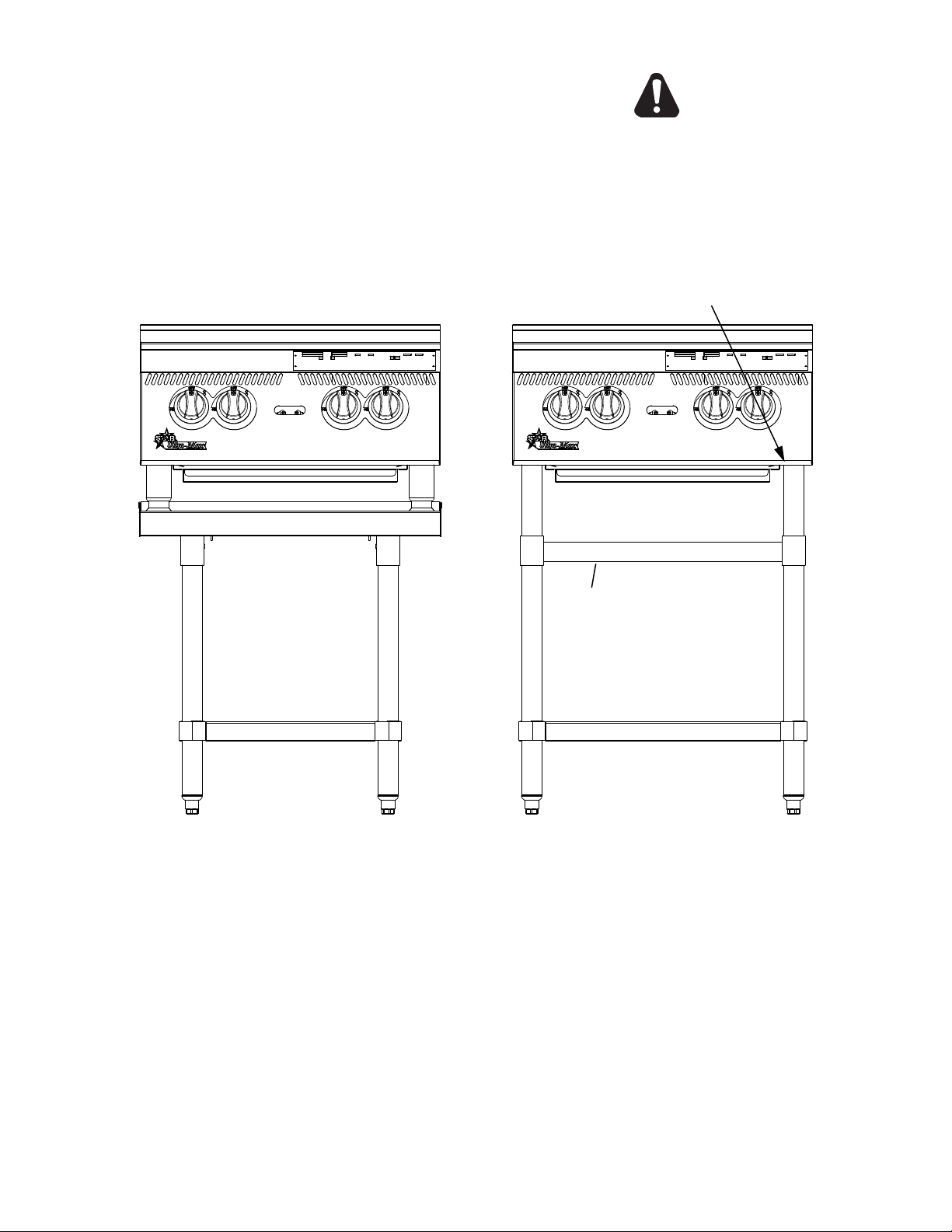
LEVELING UNIT
This charbroiler is supplied with 4 feet or oor stand
legs which must be screwed into the body. Unit must be
level. Level unit by adjusting the (4) feet which have an
adjustment of 1-3/4" for accurate and perfect line-up with
other units.
CAUTION
DO NOT INSTALL WITHOUT ATTACHING FEET
OR SUPPLIED STAND LEGS AND SHELF -
DO NOT REMOVE FEET.
SCREW LEGS INTO
MOUNTING NUTS ON BOTTOM
STIFFENING SUPPORTS FOR
8148, 8160 & 8172 MODELS ONLY
FLOOR STAND SHELF
FLOOR STAND MODELCOUNTER TOP MODEL
ON OPTIONAL EQUIPMENT STAND
Caster Kits: Casters can be used with oor stand models or optional equipment stand. For installation, carefully
mark and cut off from the bottom of each leg using a straight cutting saw and de-burr the inside tube wall prior
to installing the caster. Cut leg should measure 19" tube length, not overall length. Casters add about 6-1/4" of
2M-Z20327, Ultra-Max Gas Char-broiler
height to the unit. Be sure to use approved strain relief means for protecting gas line connection. If an appliance
is equipped with casters and is gas connected with a quick connect coupling, all personnel must be aware that
there is a restraint on the appliance and if disconnected for service or cleaning it must be reconnected as originally
installed prior to use.
IL2505
5

GENERAL INSTALLATION DATA (continued)
PLACING RADIANTS - RCBB SERIES
After the unit is unpacked and installed, place 1 radiant above each burner. Install each radiant on 2
slots of the rear wall and on 1 pin of the front wall of the liner weld assembly. Refer to the exploded view
in this manual for orientation of the radiants.
PLACING LAVA ROCKS- CBB SERIES
Open the lava rock bags and place rock evenly on the lower internal grates - not the top cooking grates.
Spread the lava rock evenly on the grates approximately 1 layer thick. Do not cover the grates with
more than two layers of lava rock. Do not put more than 5 pounds of rock per foot, or for every two
burners. NOTE: To much rock will deect the heat downward.
GAS PIPING
Gas piping shall be of such size and so installed as to provide a supply of gas sufcient to meet the
full gas input of the appliance. If the appliance is to be connected to existing piping, it shall be checked
to determine if it has adequate capacity. Joint compound shall be used sparingly and only on the male
threads of the pipe joints. Such compounds shall be resistant to the action of L.P. gases. WARNING:
Any loose dirt or metal particles which are allowed to enter the gas lines on this appliance will damage
the valve and affect its operation. When installing this appliance, all pipe and ttings must be free from
all internal loose dirt.
GAS PRESSURE REGULATOR
A convertible pressure regulator is provided with each charbroiler. It should be connected to the inlet pipe
at the rear of the unit. The gas supply is then connected to it. The supply pressure to the regulator is not to
exceed 1/2 PSIG. It is shipped set for 5" water column manifold pressure for use with natural gas.
CAUTION
MANUAL SHUT OFF VALVE
A manual shut off valve should be installed upstream from the manifold and within six feet of the
charbroiler.
CONNECTING GAS SUPPLY LINE
The gas inlet of the charbroiler is sealed at the factory to prevent entry of dirt. Do not remove this seal
until the actual connection is made to the gas supply line.
PROPANE GAS - CONVERSION
This charbroiler is equipped with xed orice hoods and is shipped from the factory for use with natural
gas. To convert to propane gas, install the burner orice hoods, located in the water pan, as follows:
1. Remove grates, radiants and burners.
2. Remove the burner orice hoods (NAT #47) and install the orice hoods (LP #55) supplied.
3. Replace the burners, radiants, and grates.
4. Set manifold pressure to (10) inch water column. A 1/8" pipe plug on the burner manifold can
be removed for attaching a pressure gauge. Remove the slotted, or hex-threaded plug from the
pressure regulator. Invert the plug and re-install. The letters "LP" should now be visible on the
plug. The regulator is now set for 10" (25.4 cm) water column. Attach the conversion label, supplied
with the unit, close to the nameplate.
CHECKING FOR GAS LEAKS
Check entire piping system for leaks. Soap and water solution or other material acceptable for the
purpose, shall be used in locating gas leakage.
2M-Z20327, Ultra-Max Gas Char-broiler
Matches, candle ame or other sources of ignition shall not be used for locating
gas leaks.
PILOT LIGHTING INSTRUCTIONS
The charbroiler is equipped with standing pilots, and should be lit immediately after the gas is turned on.
1. Turn off main valve to unit.
2. Turn off all knobs and pilot valves and wait 5 minutes to clear gas.
3. The pilot lights on this broiler have been pre-set at the factory. Turn the adjustable screw
counterclockwise to open and clockwise to close.
6
 Loading...