

Star Manufacturing 175 Installation Manual

FOR YOUR SAFETY
Modular
In-Direct Fired
Heater
s and Inserts
Installation, Operation, and Maintenance Manual
Modular
In-
Direct
Fired
Heater
In-Direct Fired Module
Save the
se instructions
RECEIVING AND INSPECTION
WARNING!!
FOR YOUR SAFETY
If you smell gas:
1. Open windows.
2. Don’t touch electrical switches.
3. Extinguish any open flames.
In-Direct Fired Furnace
4. Immediately call your gas supplier.
The use and storage of gasoline or other flammable vapors and liquids in open containers in the
vicinity of this appliance is hazardous.
Upon receiving unit, check for any interior and exterior damage, and if found, report it
immediately to the carrier. Also check that all accessory items are accounted for and are
damage free. Turn the blower wheel by hand to verify free rotation and check the damper (if
supplied) for free operation.
Improper installation, adjustment, alteration, service or maintenance can cause property
damage, injury or death. Read the installation, operating and maintenance instructions
thoroughly before installing or servicing this equipment. ALWAYS disconnect power and gas
prior to working on heater.
. This document is the property of the owner of this equipment and is
required for future maintenance. Leave this document with the owner when installation or
service is complete.
August 2009 Rev. 15

TABLE OF CONTENTS
WARRANTY ............................................................................................................................................ 3
INSTALLATION ....................................................................................................................................... 4
Mechanical .......................................................................................................................................... 4
Site Preparation .............................................................................................................................. 4
Assembly ........................................................................................................................................ 4
Curb and Ductwork ......................................................................................................................... 4
Roof Mount Installation .................................................................................................................... 5
Installation with Exhaust Fan ........................................................................................................... 5
In-Direct Fired Module Installation ................................................................................................... 6
Indoor (INLINE) Installation ............................................................................................................. 6
Indoor Flue Venting ......................................................................................................................... 7
Gas ..................................................................................................................................................... 8
Electrical ............................................................................................................................................. 9
Motorized Intake Damper ................................................................................................................ 9
Remote Control Panel ................................................................................................................... 10
Fan to Building Wiring Connection ................................................................................................. 10
OPERATION ......................................................................................................................................... 11
Start Up ............................................................................................................................................. 11
Special Tools Required ................................................................................................................. 11
Start Up Procedure ....................................................................................................................... 11
Pilot Adjustment ............................................................................................................................ 11
Main Burner Adjustment ................................................................................................................ 12
Furnace Start Up Summary ........................................................................................................... 13
Final Start Up Procedure ............................................................................................................... 14
Pulley Adjustment ......................................................................................................................... 15
Pulley Alignment ........................................................................................................................... 15
Proper Belt Tension ...................................................................................................................... 15
Pulley Combination Chart .............................................................................................................. 16
Sequence of Operation ...................................................................................................................... 16
Modulating Gas System ................................................................................................................ 16
Flame Safety Control ..................................................................................................................... 17
Operation Summary ...................................................................................................................... 17
Optional Remote Panel Circuit ...................................................................................................... 18
Components ...................................................................................................................................... 19
Remote Panel Option .................................................................................................................... 20
Troubleshooting ................................................................................................................................ 21
Airflow Troubleshooting Chart ....................................................................................................... 21
Furnace Troubleshooting Chart ..................................................................................................... 22
Remote Panel Troubleshooting Chart ............................................................................................ 23
Troubleshooting Flowcharts........................................................................................................... 24
MAINTENANCE .................................................................................................................................... 25
General Maintenance ........................................................................................................................ 25
2 weeks after startup ......................................................................................................................... 26
Every 3 months ................................................................................................................................. 26
Filter Quantity Chart ...................................................................................................................... 26
Yearly................................................................................................................................................ 26
Orifice and Gas Consumption Chart .............................................................................................. 27
Start-Up and Maintenance Documentation ........................................................................................ 28
Job Information ............................................................................................................................. 28
Heater Information ........................................................................................................................ 28
Maintenance Record ..................................................................................................................... 28
Factory Service Department .......................................................................................................... 28

3
WARRANTY
This equipment is warranted to be free from defects in materials and workmanship, under normal use and
service, for a period of 12 months from date of shipment. This warranty shall not apply if:
1. The equipment is not installed by a qualified installer per the MANUFACTURER’S installation
instructions shipped with the product,
2. The equipment is not installed in accordance with federal, state and local codes and regulations,
3. The equipment is misused or neglected,
4. The equipment is not operated within its published capacity,
5. The invoice is not paid within the terms of the sales agreement.
The MANUFACTURER shall not be liable for incidental and consequential losses and damages
potentially attributable to malfunctioning equipment. Should any part of the equipment prove to be
defective in material or workmanship within the 12-month warranty period, upon examination by the
MANUFACTURER, such part will be repaired or replaced by MANUFACTURER at no charge. The
BUYER shall pay all labor costs incurred in connection with such repair or replacement. Equipment shall
not be returned without MANUFACTURER’S prior authorization and all returned equipment shall be
shipped by the BUYER, freight prepaid to a destination determined by the MANUFACTURER.

4
INSTALLATION
CLEARANCES
IMPORTANT
It is imperative that this unit is installed and operated with the designed airflow, gas, and electrical supply
in accordance with this manual. If there are any questions about any items, please call the service
department at 1-866-784-6900 for warranty and technical support issues.
Mechanical
WARNING: DO NOT RAISE VENTILATOR BY THE INTAKE HOOD, BLOWER OR
MOTOR SHAFT, OR BEARINGS – USE LIFTING LUGS PROVIDED OR A SLING
Site Preparation
1. Provide clearance around installation site to safely rig and
lift equipment into its final position. Supports must
adequately support equipment. Refer to manufacturer’s
estimated weights.
2. Consider general service and installation space when
locating unit.
3. Locate unit close to the space it will serve to reduce long,
twisted duct runs.
4. Do not allow air intake to face prevailing winds. Support
unit above ground or at roof level high enough to prevent
precipitation from being drawn into its inlet. The inlet must
also be located at least 10 feet away from any exhaust
vents. The heater inlet shall be located in accordance
with the applicable building code provisions for ventilation
air.
Assembly
Intakes, curbs and downturn plenums are shipped unassembled.
Upon unit arrival, follow the following procedure to assemble the
intake and downturn plenum (if down discharge) to the heater.
1. Apply silicone or weather-proof gasket on the back side of
the flanges of the intake hood or v-bank intake.
2. Screw the flanges of the intake hood or v-bank to the unit with the supplied sheet metal screws.
If the unit is a modular unit with a v-bank or evaporative cooler section, the v-bank or evaporative
cooler will bolt to the heater with the bolts provided. Place caulk on the outside of the screws to
prevent water leaks.
3. If the unit is a down discharge unit, bolt
the downturn plenum to the indirect
fired module with the provided bolts.
The doors of the indirect fired module
provide access to install the bolts into
the downturn plenum. Ensure that seal
closes properly.
The top, back, and front
surfaces of this heater may not
be installed less than 6” from
combustible materials. The
heater base may be installed
on combustible surfaces.
Allow 24” minimum service
clearance on both sides of this
heater.
To prevent premature heat
exchanger failure, do not
locate any gas fired unit in
areas where chlorinated,
halogenated, or acid vapors
are present in the atmosphere.
Curb and Ductwork
This fan was specified for a specific CFM and
static pressure. The ductwork attached to this
unit will significantly affect the airflow performance. Flexible ductwork and square elbows should not be
used. Also, transitions and turns in ductwork near the fan outlet will cause system effect and will

5
Blower Size
Straight Duct Length
15 72 in.
18 86 in.
drastically increase the static pressure and
reduce airflow. The chart below shows the
minimum fan outlet duct sizes and straight
lengths recommended for optimal fan
performance. Follow SMACNA guides and
recommendations for the remaining duct
run. Fans designed for rooftop installation
should be installed on a prefabricated or factory built roof curb. Follow curb manufacturer’s instructions
for proper curb installation. The unit should be installed on a curb and/or rail elevated not less than 20”
above any surface. Be sure duct connection and fan outlet are properly aligned and sealed. Secure fan
to curb through vertical portion of the ventilator base assembly flange using a minimum of eight (8) lug
screws, anchor bolts, or other suitable fasteners (not furnished). Shims may be required depending upon
curb installation and roofing material. Check all fasteners for tightness. The diagrams below show
different mechanical installation configurations.
Recommended Supply Ductwork Sizes
10 48 in.
Roof Mount Installation
Installation with Exhaust Fan

6
In-Direct Fired Module Installation
Indoor (INLINE) Installation
Indoor Flue Venting
Indoor gas fired heating equipment must be vented. Do not operate un-vented. Gas fired heating
equipment which has been improperly vented, or which experiences a blocked vent condition may emit
flue gases into heated spaces.
1. Installation of venting must conform with local building codes, or in the absence of local codes,
with the National Fuel Gas Code.
2. Do not use a vent pipe smaller than the size of the outlet on the heater.
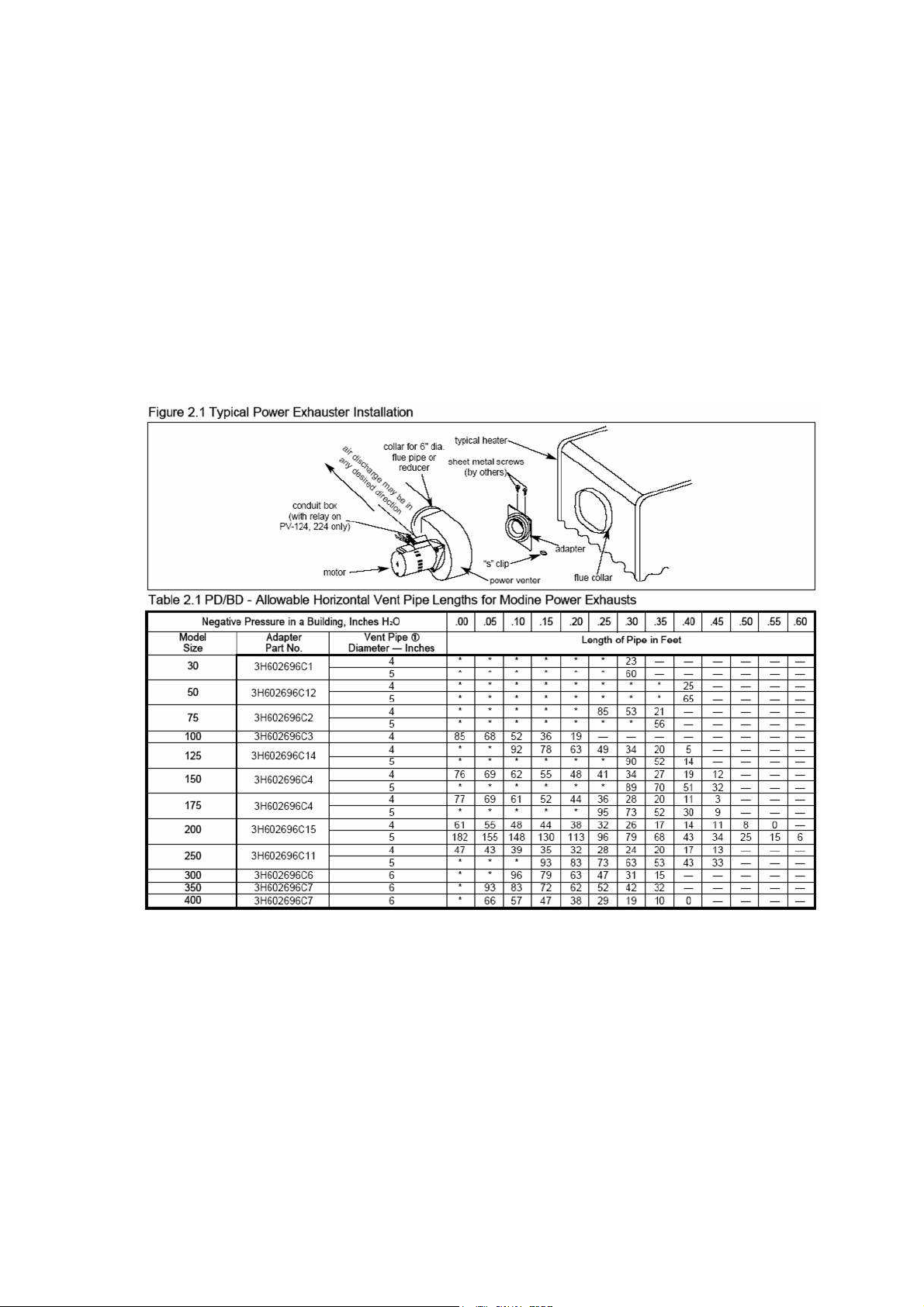
3. Reference Table 2.1. Length of horizontal vent pipe should not exceed the values given in this
chart based on Model size. Install with a minimum upward slope from unit of ¼ inch per foot and
suspend from overhead structure at points no greater than 3 feet apart. For best venting, put as
much vertical vent as close to the unit as possible.
4. Fasten individual lengths of vent together with at least three corrosion resistant sheet metal
screws.
5. Vent pipes should be fitted with a tee with a drip leg and clean out tap at the low point in the vent
run. This should be inspected and cleaned out periodically during the heating season.
6. Do NOT use dampers or other devices in the vent or combustion air pipes.
7. Use a vent terminal to reduce downdrafts and moisture in the vent line.
8. When venting into a common vent, the individual vents should enter at different levels. The area
of the common vent should be equal to or greater than the area of the largest vent plus 50% of
the area of all additional vents.
August 2009 Rev. 15

8
Gas
NOTICE
Installation of gas piping must conform with local building codes, or in the absence of local codes, with the
National Fuel Gas Code, ANSI Z223.1 (NFPA 54) – latest edition. In Canada, installation must be in
accordance with CAN/CGA-B149.1 for natural gas units and CAN/CGA-B149.2 for propane units.
WARNING: INLET GAS PRESSURE MUST NOT EXCEED 14 IN. W.C. SEE UNIT
RATING PLATE FOR PROPER GAS SUPPLY PRESSURE AND GAS TYPE.
1. Always disconnect power before working on or near a heater. Lock and tag the disconnect
switch or breaker to prevent accidental power up.
2. Piping to the unit should conform with local and national requirements for type and volume of gas
handled, and pressure drop allowed in the line. Refer to the Gas Engineer’s Handbook for gas
line capacities.
3. The incoming pipe near the heater should be sized to
match the connection on the outside of the unit. Unit
inlet sizes are shown in the table to the right. Avoid
multiple taps in the gas supply so the unit has a steady
supply of gas at all times.
4. Install a ground joint union with brass seat and a
manual shut-off valve external to the unit casing, as
shown below, adjacent to the unit for emergency shut-off and easy servicing of controls.
5. Provide a sediment trap, as shown below, before each unit and where low spots in the pipe line
cannot be avoided.
6. Blow out the gas line to remove debris before making connections. Purge line to remove air
before attempting to start unit. Purging of air from gas lines should be performed as described in
ANSI Z223.1-latest edition “National Fuel Gas Code”, or in Canada in CAN/CGA-B149.
7. All field gas piping must be pressure/leak tested prior to unit operation. Use a non-corrosive
bubble forming solution or equivalent
for leak testing. The heater and its
individual shut-off valve must be
disconnected from the gas supply
piping system during any pressure
testing of that system at test
pressures in excess of ½ psi. The
heater must be isolated from the gas
supply piping system by closing its
individual manual shutoff valve
during any pressure testing of the
gas supply piping system at test pressures equal to or less than ½ psi. This must be performed
on an annual basis.
8. This unit requires a constant 7 in. w.c. minimum natural gas supply, (LP should be 11 in. w.c.
minimum) when the unit is operating at maximum gas flow. If the gas supply exceeds 14 in.
w.c. it will damage the internal valve components, and if it is below 7 in. w.c., the heater may not
perform to specifications.
Refer to the heater rating
plate for determining the
minimum gas supply
pressure for obtaining the
maximum gas capacity for
which this heater is specified.
Max. Manifold Pressure - Natural Gas 3.5 in. w.c. maximum
Max. Manifold Pressure - Propane 10 in. w.c. maximum
Min. Manifold Pressure - Natural Gas 0.56 in. w.c. maximum
Min. Manifold Pressure - Propane 1.6 in. w.c. maximum
Gas Pressure Type Gas Pressure
Inlet Pressure - Natural Gas 7 in. w.c. – 14 in. w.c.
Inlet Pressure - Propane 11 in. w.c. – 14 in. w.c.
Gas Connection Sizes
Unit Size Gas Pipe Size (NPT)
Size 1 ¾”
Size 2 1”
Size 3 1”
Gas Pressure Table
Gas Connection Diagram

9
Wire Size AWG
Maximum Amps
14 15
10 30
8 50
Electrical
WARNING!!
Before connecting power to the heater, read and understand this
entire section of this document. As-built wiring diagrams are
furnished with each fan by the factory, and are attached to the
door of the unit.
Electrical wiring and connections should be done in accordance
with local ordnances and the National Electric Code,
ANSI/NFPA70. Be sure the voltage and phase of the power
supply and the wire amperage capacity is in accordance with the
motor nameplate. For additional safety information refer to AMCA publication 410-96, Recommended
Safety Practices for Users and Installers of Industrial and Commercial Fans.
Disconnect power before
installing or servicing fan. High
voltage electrical input is
needed for this equipment. This
work should be performed by a
qualified electrician.
1. Always disconnect power before working on or near a
heater. Lock and tag the disconnect switch or breaker
to prevent accidental power up.
2. An electrical drop containing the motor power wiring is
shipped with every fan. The electrical drop should be
brought through one of the conduit openings located in
the base of the unit, run through the curb, and
connected to a junction box inside the building.
3. A dedicated branch circuit should supply the motor
circuit with short circuit protection according to the National Electric Code. This dedicated branch
should be run to the junction box mentioned above and connected as shown in a following
illustration labeled “Fan to Building Wiring Connection”.
4. Make certain that the power source is compatible with the requirements of your equipment. The
heater nameplate identifies the proper phase and voltage of the motor.
5. Units shipped with an optional remote
panel have two electrical circuit drops.
It is important to run the motor wires in
a separate conduit from the remote
control wiring. The DC wires from the
unit temperature controller, located in
the control drop, should either be
shielded cable or be run in a separate
conduit.
6. Before connecting heater to the
building power source, verify power
line wiring is de-energized.
7. Secure the power cables to prevent
contact with sharp objects.
8. Do not kink power cable and never allow the cable to come in contact with oil, grease, hot
surfaces or chemicals.
9. Before powering up the heater, check fan wheel for free rotation and make sure that the interior of
the heater is free of loose debris or shipping materials.
10. If any of the original wire supplied with the heater must be replaced, it must be replaced with type
THHN wire or equivalent.
Copper Wire Ampacity
12 20
6 65
Motorized Intake Damper
On units shipped with the optional motorized intake damper, a power transformer is supplied with the unit
if the main incoming voltage is greater than 120V. The damper motor is automatically energized when
the main disconnect switch is in the ON position. No external wiring to the damper motor is required.
 Loading...