

Page 1
1
ENGLISH
FRANCAIS 42
ESPANGOL 82
DEUTSCH 22
NEDERLANDS 62
ITALIANO 102
STA-RITE
®
VS2
VARIABLE SPEED PUMPS - SECOND GENERATION
SUPERMAX™-VS2 & S5P2R®-VS2
INSTALLATION GUIDE / INSTALLATIEHANDLEIDING
BEDIENUNGSANLEITUNG / GUIDE DE L’INSTALLATION
GUIA DE INSTALACION / GUIDE ALL’INSTALLAZIONE
IMPORTANT SAFETY INSTRUCTIONS READ AND FOLLOW ALL INSTRUCTIONS SAVE THESE INSTRUCTIONS
WATER SOLUTIONS P-INSB-STVS2 (Rev. 10/2016)
ENGLISH 2
Page 2
2
ENGLISH
This unit must be connected only to a supply circuit
that is protected by a ground-fault circuit-interrupter
(GFCI). Such a GFCI should be provided by the installer and should be tested on a routine basis. To test the GFCI, push the
test button. The GFCI should interrupt power. Push the reset button. Power
should be restored. If the GFCI fails to operate in this manner, the GFCI
is defective. If the GFCI interrupts power to the pump without the test button being pushed, a ground current is owing, indicating the possibility of
an electric shock. Do not use this pump. Disconnect the pump and have
the problem corrected by a qualied service representative before using.
IMPORTANT PUMP WARNING AND SAFETY INSTRUCTIONS
When installing and using this electrical equipment, basic safety
precautions should always be followed, include the following:
Do not permit children to use this product.
RISK OF ELECTRICAL SHOCK. Connect
only to a branch circuit protected by a groundfault circuit-interrupter (GFCI). Contact a qualied electrician if you
cannot verify that the circuit is protected by a GFCI.
This pump is for use with permanent swimming pools
and may also be used with hot tubs and spas if so
marked. Do not use with storable pools. A permanent-
ly-installed pool is constructed in or on the ground or in
a building such that it cannot be readily disassembled for storage. A storable
pool is constructed so that it is capable of being readily disassembled for
storage and reassembled to its original integrity.
General Warnings
• Never open the inside of the drive motor enclosure. There is a capacitor
bank that holds a 230 VAC charge even when there is no power to the
unit.
• The pump is not submersible.
• The pump is capable of high flow rates; use caution when installing
and programming to limit pumps performance potential with old or
questionable equipment.
• Code requirements for the electrical connection dier from state to state.
Install equipment in accordance with the current National Electrical
Code and all applicable local codes and ordinances.
• Before servicing the pump; switch OFF power to the pump by
disconnecting the main circuit to the pump.
• This appliance is not intended for use by persons (including children) of
reduced physical, sensory or mental capabilities, or lack of experience
and knowledge, unless they have been given supervision or instruction
concerning the use of the appliance by a person responsible for their safety.
• Sucient equipotential bonding (min. 4.5mm2 recommended), in
accordance with local regulation, is required on all metal components
of the pool including the pool pump. It is required for electrical safety
as well as to reduce the risk of corrosion.
FAILURE TO FOLLOW ALL INSTRUCTIONS AND
WARNINGS CAN RESULT IN SERIOUS BODILY INJURY OR DEATH. THIS PUMP SHOULD BE INSTALLED
AND SERVICED ONLY BY A QUALIFIED POOL SERVICE PROFESSIONAL.
INSTALLERS, POOL OPERATORS AND OWNERS MUST READ THESE
WARNINGS AND ALL INSTRUCTIONS IN THE OWNER’S MANUAL BEFORE
USING THIS PUMP. THESE WARNINGS AND THE OWNER’S MANUAL
MUST BE LEFT WITH THE POOL OWNER.
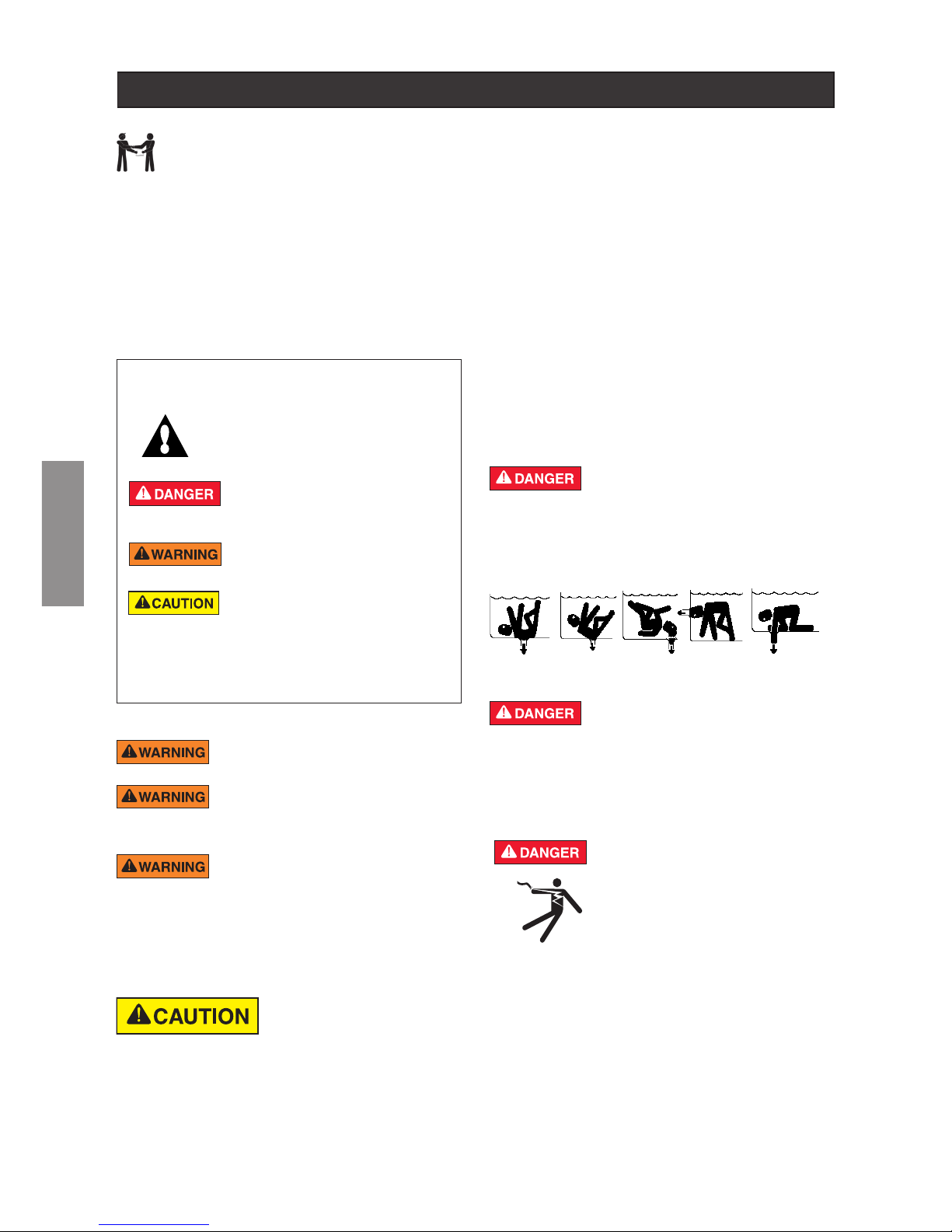
SUCTION ENTRAPMENT HAZARD: STAY
OFF THE MAIN DRAIN AND AWAY FROM ALL
SUCTION OUTLETS!
F
THIS PUMP PRODUCES HIGH LEVELS OF SUCTION AND CREATES A
STRONG VACUUM AT THE MAIN DRAIN AT THE BOTTOM OF THE BODY
OF WATER. THIS SUCTION IS SO STRONG THAT IT CAN TRAP ADULTS
OR CHILDREN UNDER WATER IF THEY COME IN CLOSE PROXIMITY
TO A DRAIN OR A LOOSE OR BROKEN DRAIN COVER OR GRATE.
This is the safety alert symbol. When you see this
symbol on your system or in this manual, look for
one of the following signal words and be alert to
the potential for personal injury.
Warns about hazards that can cause death,
serious personal injury, or major property damage
if ignored.
Warns about hazards that may cause death,
serious personal injury, or major property damage
if ignored.
Warns about hazards that may or can cause minor
personal injury or property damage
if ignored.
NOTE indicates special instructions not related to hazards.
Carefully read and follow all safety instructions in this manual and on
equipment. Keep safety labels in good condition; replace if missing
or damaged.
READ AND FOLLOW ALL INSTRUCTIONS
SAVE THESE INSTRUCTIONS
IMPORTANT NOTICE
This guide provides installation and operation instructions
for the VS2 Variable Speed Pump. Consult Pentair with any
questions regarding this equipment.
Attention Installer: This guide contains important information about the
installation, operation and safe use of this product. This information should
be given to the owner and/or operator of this equipment after installation
or left on or near the pump.
Attention User: This manual contains important information that will help
you in operating and maintaining this product. Please retain it for future
reference. Warnings and safety instructions for Pentair Aquatic Systems.
Pumps and other related products are available at:
http://www.pentairpool.com/pool-owner/safety-warnings/ for additional
free copies of these instructions.
RISK OF ELECTRICAL SHOCK OR ELECTROCUTION: PUMPS REQUIRE HIGH VOLTAGE WHICH
CAN SHOCK, BURN, OR CAUSE DEATH. BEFORE
WORKING ON PUMP! Always disconnect power to
the pool pump at the circuit breaker from the pump
before servicing the pump. Failure to do so could result
in death or serious injury to service person, pool users
or others due to electric shock.
THE USE OF UNAPPROVED COVERS OR ALLOWING USE OF THE
POOL OR SPA WHEN COVERS ARE MISSING, CRACKED OR BROKEN
CAN RESULT IN BODY OR LIMB ENTRAPMENT, HAIR ENTANGLEMENT,
BODY ENTRAPMENT, EVISCERATION AND/OR DEATH.
The suction at a drain or outlet can cause:
Limb Entrapment: When a limb is sucked or inserted into an opening
resulting in a mechanical bind or swelling. This hazard is present when
a drain cover is missing, broken, loose, cracked or not properly secured.
Hair Entanglement: When the hair tangles or knots in the drain cover, trapping the swimmer underwater. This hazard is present when the ow rating
of the cover is too small for the pump or pumps.
Page 3
3
ENGLISH
The pump can produce high levels of suction within
the suction side of the plumbing system. These high
levels of suction can pose a risk if a person comes
within the close
proximity of the suction openings. A person can be seriously injured by this
high level of vacuum or may become trapped and drown. It is
absolutely critical that the suction plumbing be installed in accordance with
the latest national and local codes for swimming pools.
For Installation of Electrical Controls at Equipment Pad (ON/OFF
Switches, Timers and Automation Load Center)
Install all electrical controls at equipment pad, such
as on/o switches, timers, and control systems, etc. to
allow the operation (startup, shut-down, or servicing)
of any pump or filter so the user does not place any
portion of his/her body over or near the pump strainer
lid, lter lid or valve closures. This installation should
allow the user enough space to stand clear of the
lter and pump during system start-up, shut down or
servicing of the system lter.
Pentair Water Pool and Spa
®
IMPORTANT SAFETY INSTRUCTIONS
For Installation of Electrical Controls at Equipment Pad
(ON/OFF Switches, Timers and Aut omation Load Center)
Install all electrical controls at equipment pad, such as on/off
switches, timers, and control systems, etc. to allow the
operation (startup, shut-down, or servicing) of any pump or
filter so the user does not place any portion of his/her body
over or near the pump strainer lid, filter lid or valve closures.
This installation should allow the user enough space to stand
clear of the filter and pump during system start-up, shut down
or servicing of the system filter.
SAVE THESE INSTRUCTIONS
IMPORTANT PUMP WARNING AND SAFETY INSTRUCTIONS
Before servicing equipment, make note of the filter pressure.
Be sure that all controls are set to ensure the system cannot
inadvertently start during service. Turn o all power to the pump.
IMPORTANT: Place filter manual air relief valve in the open
position and wait for all pressure in the system to be relieved.
Before starting the system, fully open the manual air relief valve
and place all system valves in the “open” position to allow water
to ow freely from the tank and back to the tank. Stand clear of
all equipment and start the pump.
IMPORTANT: Do not close filter manual air relief valve until all
pressure has been discharged from the valve and a steady stream
of water appears. Observe lter pressure gauge and be sure it is
not higher than the pre-service condition.
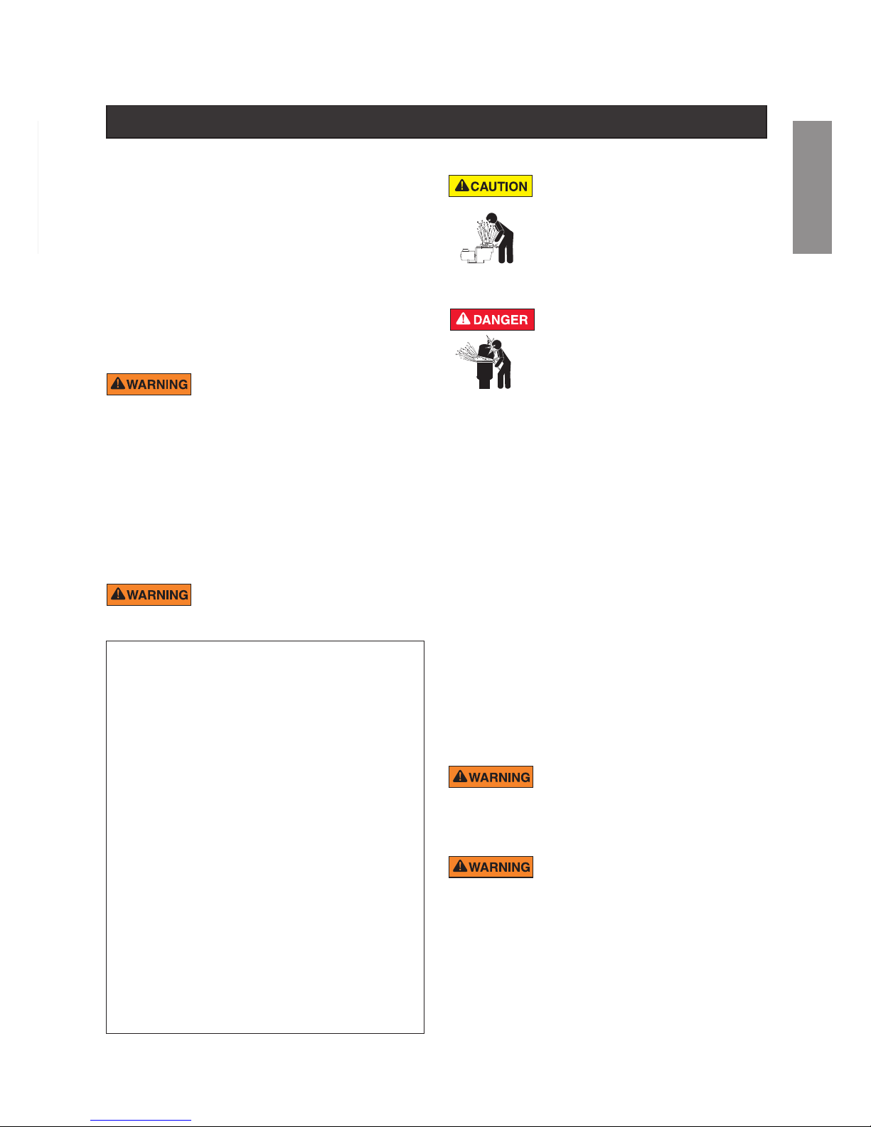
HAZARDOUS PRESSURE: STAND CLEAR
OF PUMP AND FILTER DURING START UP
Circulation systems operate under high pressure. When
any part of the circulating system (i.e. locking ring,
pump, filter, valves, etc.) is serviced, air can enter the
system and become pressurized. Pressurized air can
cause the pump housing cover, filter lid, and valves to
violently separate which can result in severe personal
injury or death. Filter tank lid and strainer cover must be
properly secured to prevent violent separation. Stand
clear of all circulation system equipment when turning on or starting up pump.
®
General Installation Information
• All work must be performed by a qualied service professional, and must
conform to all national, state, and local codes.
• Install to provide drainage of compartment for electrical components.
• These instructions contain information for a variety of pump models and therefore
some instructions may not apply to a specic model. All models are intended for
use in swimming pool applications. The pump will function correctly only if it is
properly sized to the specic application and properly installed.
• Fitting a non-return valve after the pump on the installation will prevent the
impeller from unwinding and is strongly recommended.
Pumps improperly sized or installed or used in applications other than for which the pump was intended
can result in severe personal injury or death. These
risks may include but not be limited to electric shock,
re, ooding, suction entrapment or severe injury or property damage
caused by a structural failure of the pump or other system component.
The Virginia Graeme Baker (VGB) Pool and Spa Safety
Act creates new requirements for owners and operators of
commercial swimming pools and spas.
Commercial pools or spas constructed on or after December
19, 2008, shall utilize:
(A) A multiple main drain system without isolation capability
with suction outlet covers that meet ASME/ANSI A112.19.8a
Suction Fittings for Use in Swimming Pools, Wading Pools,
Spas, and Hot Tubs and either:
(i) A safety vacuum release system (SVRS) meeting ASME/
ANSI A112.19.17 Manufactured Safety Vacuum Release
systems (SVRS) for Residential and Commercial Swimming
Pool, Spa, Hot Tub, and Wading Pool Suction Systems and/
or ASTM F2387 Standard Specification for Manufactured
Safety Vacuum Release Systems (SVRS) for Swimming
pools, Spas and Hot Tubs or
(ii) A properly designed and tested suction-limiting vent
system or
(iii) An automatic pump shut-o system.
Commercial pools and spas constructed prior to December 19,
2008, with a single submerged suction outlet shall use a suction
outlet cover that meets ASME/ANSI A112.19.8a and either:
(A) A SVRS meeting ASME/ANSI A112.19.17 and/or ASTM
F2387, or
(B) A properly designed and tested suction-limiting vent
system, or
(C) An automatic pump shut-o system, or
(D) Disabled submerged outlets, or
(E) Suction outlets shall be re-congured into return inlets.
TO MINIMIZE THE RISK OF INJURY DUE TO
SUCTION ENTRAPMENT HAZARD:
• Each suction cover must be installed at least 1 m apart,
as measured from the nearest point to nearest point.
• Regularly inspect all covers for cracks, damage and
advanced weathering.
• If a cover becomes loose, cracked, damaged, broken or
is missing, replace with an appropriate certied cover.
• Replace drain covers as necessary. Drain covers deteriorate
over time due to exposure to sunlight and weather.
• Avoid getting hair, limbs or body in close proximity to any
suction cover, pool drain or outlet.
• Disable suction outlets or recongure into return inlets.
A clearly labeled emergency shut-off switch
for the pump must be in an easily accessible,
obvious place. Make sure users know where it
is and how to use it in case of emergency.
Body Entrapment: When a portion of the body is held against
the drain cover trapping the swimmer underwater. This hazard is
present when the drain cover is missing, broken or the cover ow
rating is not high enough for the pump or pumps.
Evisceration/Disembowelment: When a person sits on an open
pool (particularly a child wading pool) or spa outlet and suction
is applied directly to the intestines, causing severe intestinal
damage. This hazard is present when the drain cover is missing,
loose, cracked, or not properly secured.
Mechanical Entrapment: When jewelry, swimsuit, hair decorations, nger, toe or knuckle is caught in an opening of an outlet
or drain cover. This hazard is present when the drain cover is
missing, broken, loose, cracked, or not properly secured.
NOTE: ALL SUCTION PLUMBING MUST BE INSTALLED IN
ACCORDANCE WITH THE LATEST NATIONAL AND LOCAL
CODES, STANDARDS AND GUIDELINES.
ENGLISH
Page 4
4
ENGLISH
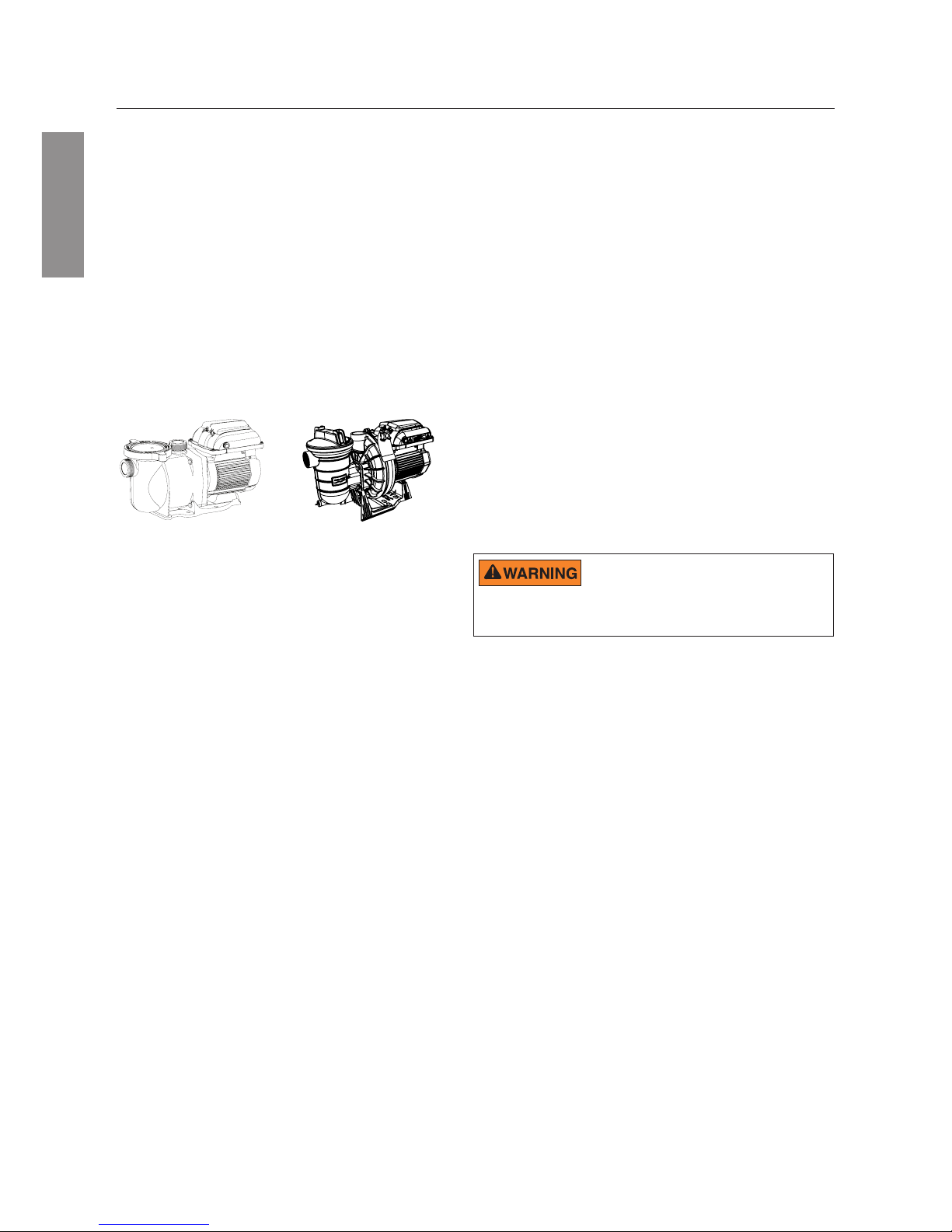
Pump Overview
The perfect choice for all types of pools, the VS2 Variable
Speed Pump was specically designed to be your best
choice for a variety of in-ground pools.
Thick walled body parts, a heavy duty TEFC motor,
and highly engineered hydraulics make this rugged and
tested design perfect for any pool, spa, water feature,
or fountain.
All pumps from Pentair Aquatic Systems incorporate
innovative hydraulic engineering that has been rened for
over 40 years. Compact, rugged, and easy to maintain,
the VS2 pump will deliver years of reliable service.
SuperMax® VS2 Pump
P/N: S5P1R-VS2
S5P2R™-VS2 Pump
P/N: S5P2R-VS2
PUMP OVERVIEW
Controller Features
• Simple user interface
• IPX6 certied UV and rain-proof enclosure
• Onboard time of day schedule
• Adjustable priming mode
• Programmable quick clean mode
• Diagnostic alarm display and retention
• Active power factor correction
General Features
• Extremely quiet operation
• Unionized ttings (1.5” and 2”) for simple
replacement
• Cam and Ramp™ Lid for easy cleaning and
maintenance
• Super-duty totally enclosed fan cooled (TEFC)
motor for long life
• Integral volute and pot reduce hydraulic noise
• See-through lid permits easy inspection of
strainer basket
• Self-priming for quick, easy start-up
• CE/REACH certied
• IPX6 rated
Controller Overview
The VS2 Variable Speed Pump uses a premium efciency
variable speed motor that provides tremendous program
flexibility in terms of motor speed and duration settings.
The pump is intended to run at the lowest speeds needed
to maintain a sanitary environment, which in turn minimizes
energy consumption. Pool size, the presence of additional water
features, chemicals used to maintain sanitary conditions, and
local environmental factors will impact optimal programming
necessary to maximize energy conservation.
The integrated electronics interface controls the speed settings
as well as the run durations. The pump can operate at speeds
ranging between 300 and 3450 RPM and will operate within
the voltage range of 99-253 Vrms at either 50 or 60Hz input
frequency.
Program customization may require some trial-anderror to determine the most satisfactory settings as dictated by
the conditions. In most cases, setting the pump at the lowest
speed for the longest duration is the best strategy to minimize
energy consumption. However, conditions may require running
the
pump
at a higher speed for some duration of time each day
to maintain proper ltration to achieve satisfactory sanitation.
Note: Optimize the pump to suit individual pool conditions.
Specic conditions including pool size, other devices, features
and environmental factors can all impact the optimal settings.
This pump is for use with 115/208-230 Vrms
nominal, and in pool pump applications ONLY.
Connection to the wrong voltage, or use in other application may cause
damage to equipment or personal injury.
• Accepts 99-253V, 50/60Hz input power
• Auto power limiting protection circuit
• 24hr. clock retention for power outages
• Keypad lockout mode
• Accepts low voltage digital inputs from external
controls
Page 5
5
ENGLISH
If power is connected to the VS2 Variable Speed Pump motor, pressing any of the following buttons
referred to in this section could result in the motor starting. Failure to recognize this could result in
personal injury or damage to equipment.
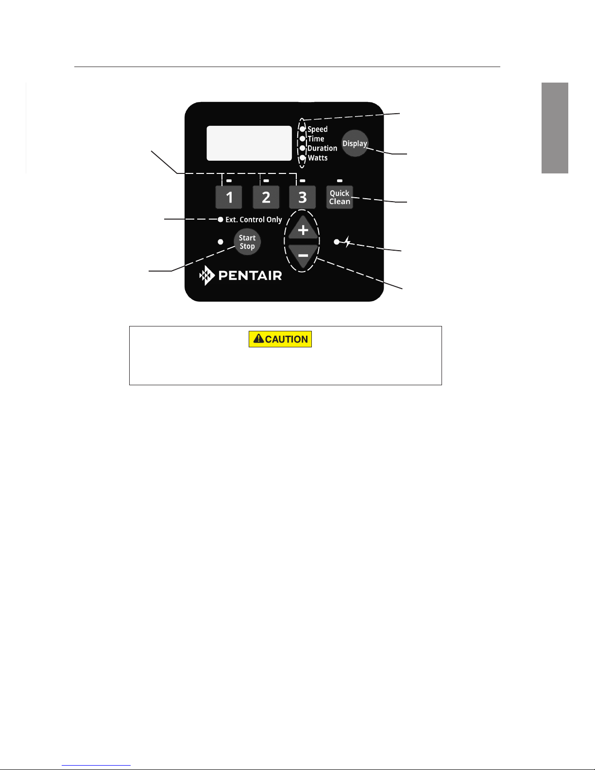
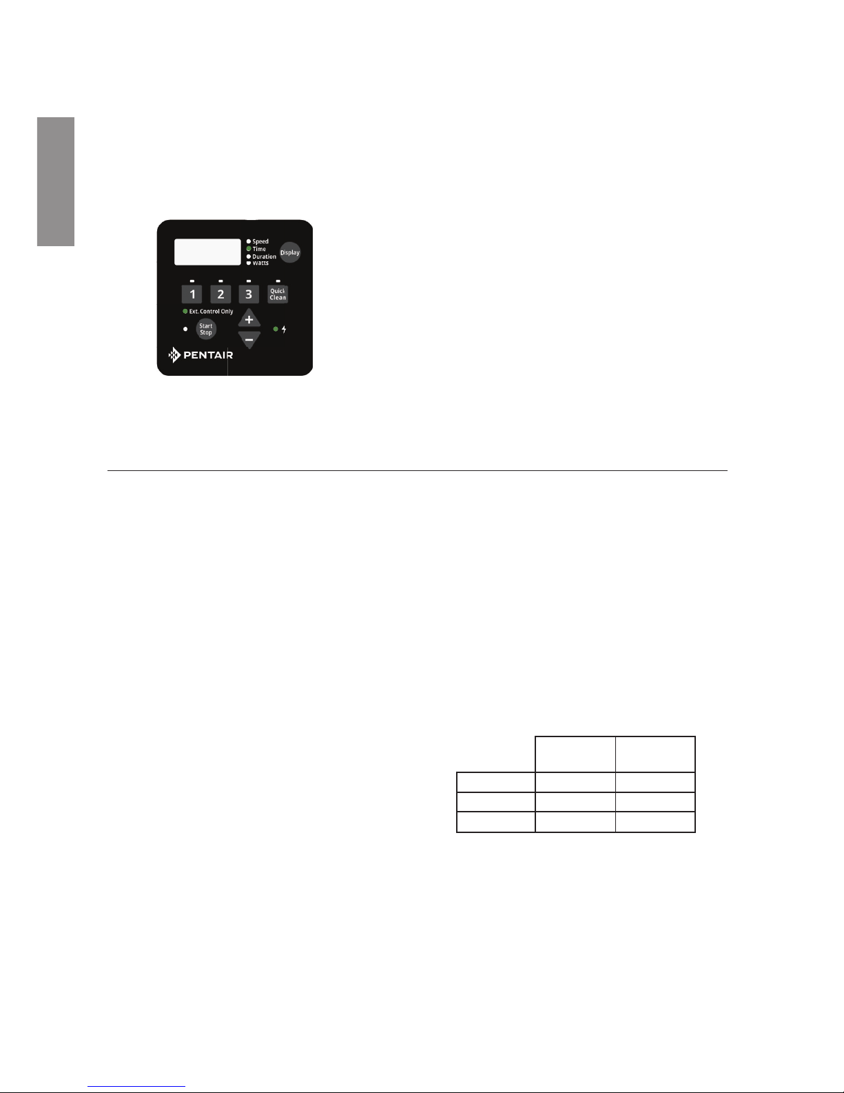
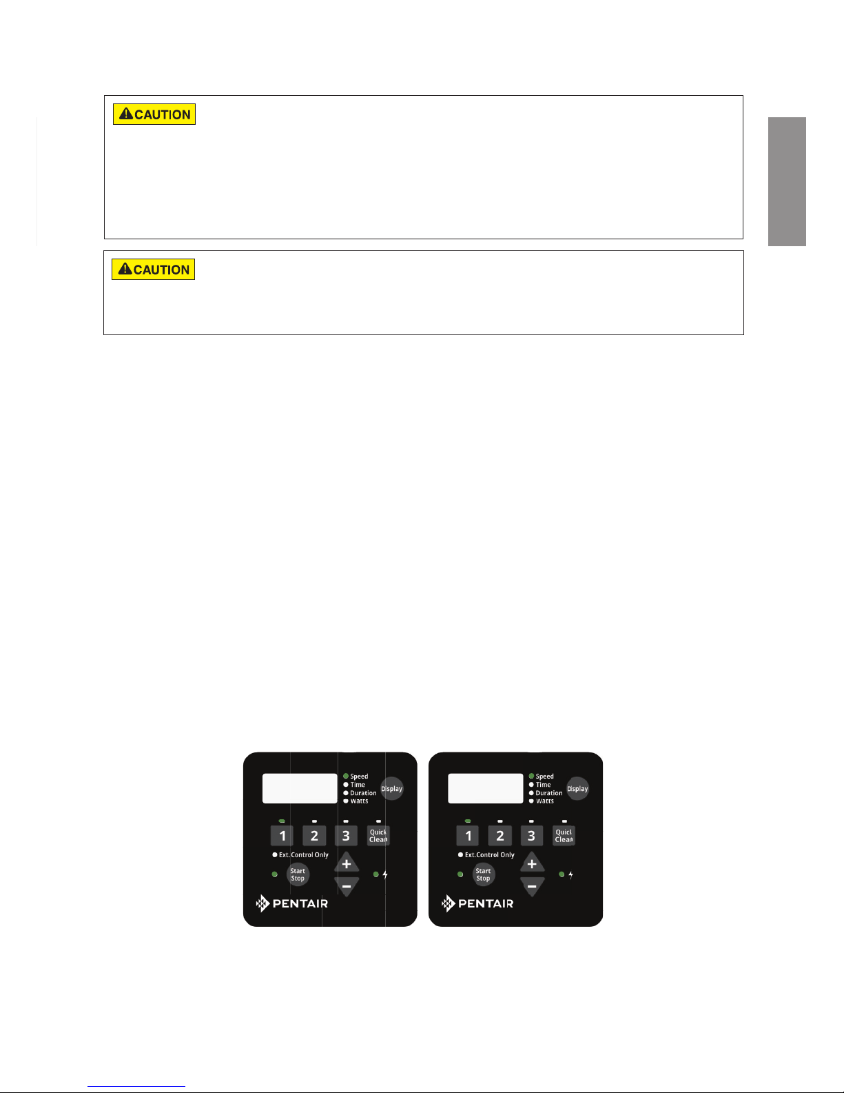
CONTROL PANEL OVERVIEW
(1) Speed Buttons
(2) External
Control Only
LED Indicator
(3) Start/Stop
Button
(7) Power LED
Indicator
(4) Display Mode
LED Indicators
(5) Display Button
(6) Quick Clean
Button
(8) “+” and “-”
Arrows
Keypad Navigation
1. Speed Buttons - Used to select the run speed desired. The LED above the Speed Buttons will
illuminate when that speed is selected or is currently running. A ashing LED indicates that an
External Control is active on that speeds channel.
2. External Control Only LED Indicator - Indicates that the pump is operating in External Control Only
mode. When LED is illuminated the schedule is disabled and the only input is from the low voltage
external controls.
3. Start/Stop Button - Used to Start and Stop the pump. When the pump is stopped and the LED is not
illuminated, the pump is unable to run from any type of input.
4. Display Mode LED Indicators - An illuminated LED indicates the information being displayed on the
screen at any specic point. A ashing LED indicates that the parameter is currently being edited.
5. Display Button - Used to toggle between the dierent available display modes. This button is also
used to set the 24-hour clock and screen resolution.
6. Quick Clean Button - Used to run a selected speed and duration programmed for Quick Clean.
When the LED is illuminated the Quick Clean schedule is active.
7. Power LED Indicator - An illuminated LED indicates that there is live power being supplied to the
pump.
8. “+” and “-” Arrows - Used to make on screen adjustments to the pump settings. The “+” arrow
increases the value of a given setting, while “-” decreases the value of a given setting. Pressing and
holding down either arrow button will increase or decrease the incremental changes faster.
ENGLISH
Page 6
6
INSTALLATION
ENGLISH
Fittings and Valves
1. Do not install 90° elbows directly into pump inlet.
2. Flooded suction systems should have gate
valves installed on suction and discharge pipes
for maintenance, however, the suction gate valve
should be no closer than ve times the suction pipe
diameter as described in this section.
3. Use a check valve in the discharge line when
using this pump for any application where there is
signicant height to the plumbing after the pump.
4. Be sure to install check valves when plumbing in
parallel with another pump. This helps prevent
reverse rotation of the impeller and motor.
Electrical Requirements
• Install all equipment in accordance with the your
national electrical code and all applicable local
codes and ordinances.
• A means for disconnection must be incorporated in
the xed wiring in accordance with the wiring rules.
Only a qualied plumbing professional should install the VS2 Variable Speed Pump. Refer to “Pump Warning
And Safety Instructions” on pages ii-iii for additional installation and safety information.
5 x SUCTION PIPE DIAMETER
ELBOW
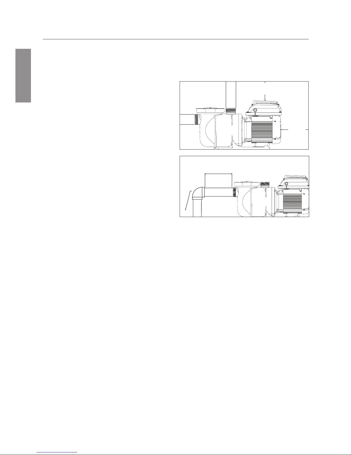
Figure 2.
Location
Note: Do not install this pump within an outer enclosure
or beneath the skirt of a hot tub or spa unless marked
accordingly.
Note: Ensure that the pump is mechanically secured to
the equipment pad.
Be sure the pump location meets the following
requirements:
1. Install the pump as close to the pool or spa as
possible. To reduce friction loss and improve
eciency, use short, direct suction and return piping.
2. Install a minimum of 1.5 meters from the inside wall
of the pool and spa.
3. Install the pump a minimum of 1 meter from the
heater outlet.
4. Do not install the pump more than 3 meters above
the water level.
5. Install the pump in a well ventilated location protected
from excess moisture (i.e. rain gutter downspouts,
sprinklers, etc.).
6. Install the pump with a rear clearance of at least
10 cm so that the motor can be removed easily for
maintenance and repair. See Figure 1.
Piping
1. For improved pool plumbing, it is recommended to
use a larger pipe size.
2. Piping on the suction side of the pump should be
the same or larger than the return line diameter.
3. Plumbing on the suction side of the pump should
be as short as possible.
4. For most installations Pentair recommends installing
a valve on both the pump suction and return lines
so that the pump can be isolated during routine
maintenance. However, we also recommend that
a valve, elbow or tee installed in the suction line
should be no closer to the front of the pump than
ve (5) times the suction line diameter. See Figure 2.
Example: A 2.5 inch pipe requires a 12.5 inch
(31.8 cm) straight run in front of the suction inlet
of the pump. This will help the pump prime faster
and last longer.
Note: DO NOT install 90° elbows directly into the
pump inlet or outlet.
10 CM
MINIMUM
Figure 1.
15.2 CM
MINIMUM
Page 7
7
ENGLISH
Note: For Canada, a 6 AWG or larger solid copper
bonding conductor is required.
7. The pump should be permanently connected to either a
circuit breaker, 2-pole timer or 2-pole relay. If AC power
is supplied by a GFCI circuit breaker, use a dedicated
circuit breaker that has no other electrical loads.
8.
Connect the pump permanently to a circuit. Make sure
no other lights or appliances are on the same circuit.
The pump must be wired according to the local electrical
codes and standards. Always refer to the National Electrical
Code. This pump should be installed by a licensed
electrician.
The pump accepts 99-253V, 50 or 60Hz single phase input
power. The terminal block connections are capable of
handling up to 10AWG solid or stranded wire. There are
also fast-on type quick connectors, however, check the local
electrical codes for the desired connection method. The
connections must be permanently made to the grounding
terminal (see Figure 3) in the eld wiring compartment
according to the local electrical code. The motor controller
will automatically regulate the pump’s speed when running
on lower voltage to keep the current below 13.2A. There is
no wiring change required to run the pump on 110V nominal
power, the same terminals are used as with high voltage
wiring.
The drive will operate on 2-phase Line-Line-Ground
electrical systems as well as Line-Neutral-Ground systems.
This pump must be permanently connected by a circuit
breaker as specied in the local electrical code.
1. Be sure all electrical breakers and switches are turned
o before wiring motor. Always wait ve (5) minutes after
disconnecting the power from the pump before opening
or servicing the drive.
2. Choose a wire size for the pump in accordance with the
current National Electrical Code and all applicable local
codes and ordinances. When in doubt use a heavier
gauge (larger diameter) wire. Be sure the wiring voltage
is within the operating range.
3. Be sure all electrical connections are clean and tight.
4. Cut wires to the appropriate length so they do not overlap
or touch when connected to the terminal board.
5. Permanently ground the motor using the ground screw
located on the inside rear of the controller interface (see
Figure 3). Use the correct wire size and type specied by
the current National Electrical Code. Be sure the ground
wire is connected to an electrical service ground.
6. Bond the motor to all metal parts of the pool structure
and to all electrical equipment, metal conduit and metal
pipping within 5 feet (1.5 M) of the inside walls of the
swimming pool, spa or hot tub in accordance with the
current National Electrical Code. UL requires use of a
solid copper bonding conductor not smaller than 8 AWG.
See Figure 3.
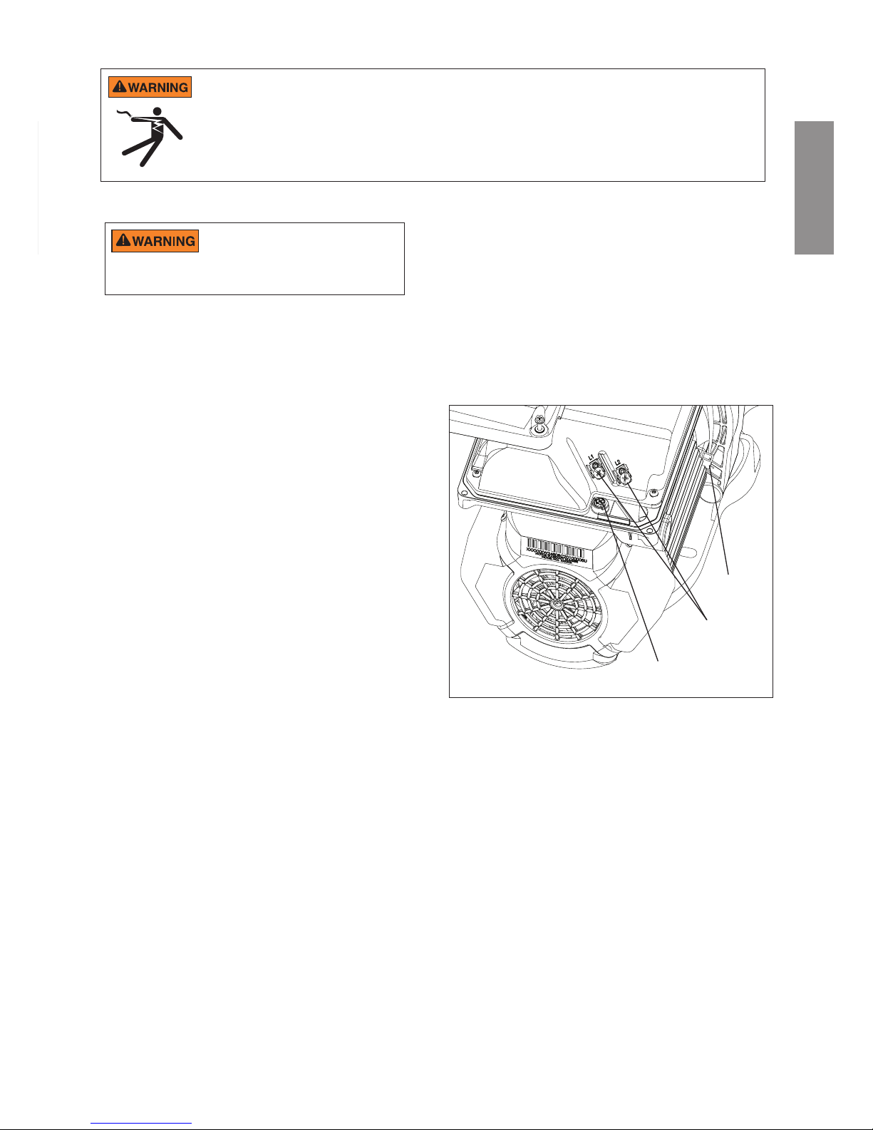
Wiring Overview and Installation
Figure 3.
Bonding
Lug
AC Power
Connections
Grounding
Terminal
The eld wiring compartment has a 1/2” NPT threaded
conduit port for the liquid tight tting.
The bonding lug should be used to bond the motor
frame to the equipment pad.
Power should be turned o when installing,
servicing, or repairing electrical components.
Observe all warning notices posted on the existing equipment, pump,
and in these installation instructions.
RISK OF ELECTRICAL SHOCK OR ELECTROCUTION. The Variable Speed Pump must be installed by a licensed or certied
electrician or a qualied service professional in accordance with the National Electrical Code and all applicable local codes and
ordinances. Improper installation will create an electrical hazard which could result in death or serious injury to users, installers, or
others due to electrical shock, and may also cause damage to property.
Always disconnect power to the pump at the circuit breaker before servicing the pump. Failure to do so could result in death
or serious injury to service people, pool users or others due to electric shock and/or property damage.
Read all servicing instructions before working on the pump.
ENGLISH
Page 8
8
ENGLISH
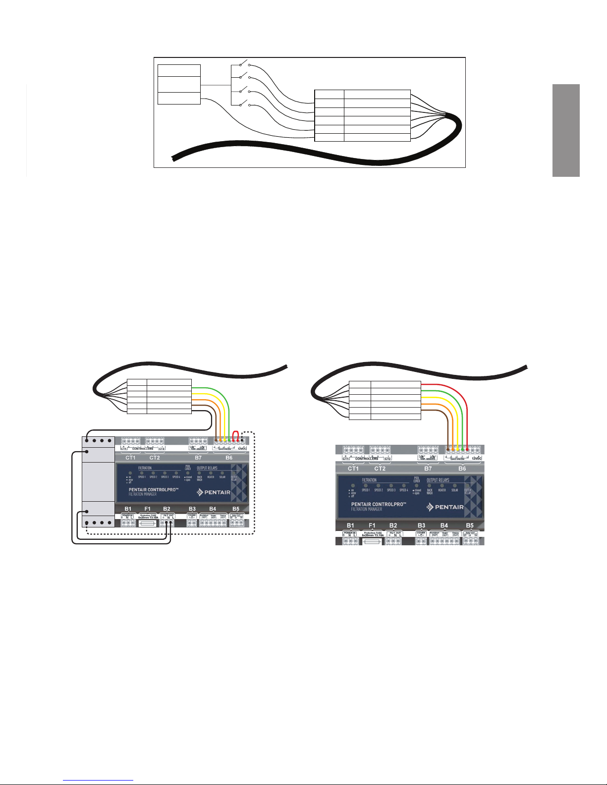
Control with External Control and Digital Inputs
The user can run the VS2 Variable Speed Pump with automation external controls or Pentair® ControlPro™, allowing all
four programmed Speeds to be controlled remotely. The pump has a sealed connector that can be used with Pentair
Data Cable (optional, P/N 353129Z) to run the Speeds using digital input signals. When there is an external low voltage
signal present on the Speed Digital Input line, the pump will run the speed programmed for that Digital Input. The
supplied +5V signal is the recommended input used for external control and Speed Digital Inputs.
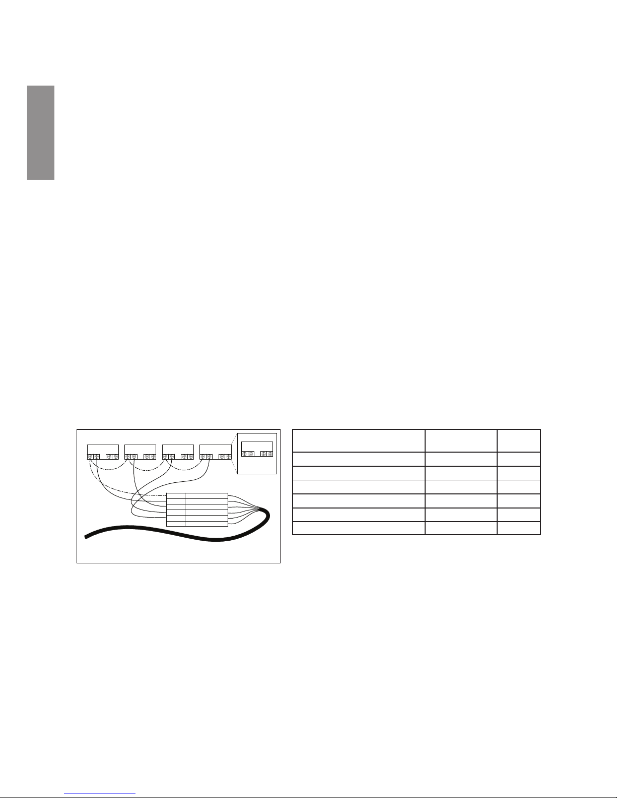
Connecting to External Controls
Using the Supplied Low Voltage Signal for Digital Control
The VS2 provides a low voltage output signal that can be used to trigger its own Digital Inputs. This signal will need to
be switched via the External Control system to engage the speed that it is connected to as in Figure 4. This could be
an automation relay or switch in another piece of equipment. This feature could be useful for ensuring that the pump is
running a certain program when a specic speed is needed to perform a task.
The wire included with the Pentair Data Cable (optional, P/N 353129Z) will need to be cut to length for the installation.
Do not leave excess wire around the installation, and the wire should be supported by something rigid if conduit is not
used. At one end of the cable is a custom molded, watertight connection that plugs into the panel connection on the side
of the drive. The opposite end has 6 wires that are dened by Table 1 below. When using the +5V signal supplied by the
drive, the speeds should be wired as shown in Figure 4.
When there is a low voltage signal present on the Speed Digital Input line the pump will run the speed that is programmed
for the speed that is being triggered. The +5V signal supplied via the (red) wire is the suggested input for the Speed
Digital Inputs. See Figure 4.
Note: Any relay can be associated to any Digital Input. Figure 4 shows one of many potential wiring options available to
the installer, allowing you to install External Controls in the way that best suits your needs.
Note: This +5V Signal (red wire) is output from the drive only, and should never be wired to another power
supply!
When a Speed Digital Input is triggered, the LED above the Speed button will begin to blink and the display will toggle
between the display parameter and “EC” indicating an External Control is running. The pump will run this speed as long
as the Digital Input trigger is present. This will override the schedule or any user inputs for Speed selections via the
keypad. The Display button is still functional along with the Start/Stop button. Once the Digital Input trigger is removed
from all of the Speed Digital Input wires, the pump will resume the programmed schedule.
RELAY 1 RELAY 2 RELAY 3 RELAY 4
RELAY
LINE 1
LOAD 1
LOAD 2
LINE 2
POWER RELAY (DPST)
RED
+5V OUTPUT FOR D.I. TRIGGERS
GREEN
SPEED 1 DIGITAL INPUT
YELLOW
SPEED 2 DIGITAL INPUT
ORANGE
SPEED 3 DIGITAL INPUT
BROWN
SPEED 4 DIGITAL INPUT
BLACK
GROUND
Figure 4:
External Control Kit Wiring Diagram
Denition Signal Range
Wire
Color
+5V Output for Digital Inputs 0 - 20mA Red
Speed 1 Digital Input 0, 5 - 30V AC/DC Green
Speed 2 Digital Input 0, 5 - 30V AC/DC Yellow
Speed 3 Digital Input 0, 5 - 30V AC/DC Orange
Quick Clean Digital Input 0, 5 - 30V AC/DC Brown
Common Ground 0V Black
Table 1:
Automation Control System Input Wiring Chart
Using an Externally Supplied Low Voltage Signal for External Control
When using an externally supplied low voltage signal as the Digital Input trigger, the wire should be connected as
shown in Figure 5. The low voltage input needs to be within the range of 5-30V AC or DC. In this case the red
+5V supply from the motor control will not be used.
Note: This +5V signal (red wire) is output from the drive only and should never be wired to a voltage supply!
The external low voltage signal can be regulated by switches or relays to activate the desired Digital Input. If
more than one Digital Input is active at one time then they will be resolved by priority.
Page 9
9
ENGLISH
RED
+5V OUTPUT FOR D.I. TRIGGER
GREEN
SPEED 1 DIGITAL INPUT
YELLOW
SPEED 2 DIGITAL INPUT
ORANGE
SPEED 3 DIGITAL INPUT
BROWN
SPEED 4 DIGITAL INPUT
BLACK
GROUND
EXTERNAL LOW
VOLTAGE SUPPLY
5-30 V AC/DC
GROUND
Note: If the pump has been stopped via the Start/Stop button, the pump will not run until the pump is turned back on
by pressing the Start/Stop button. If the Start/Stop LED is illuminated, that indicates the pump is on and will run via
Digital Inputs.
Note: If multiple low voltage triggers are present it will be resolved by this priority: Quick Clean, Speed 3, Speed 2, and
then Speed 1.
Connecting to Pentair® ControlPro™
When looking for external controlled installation, Pentair® ControlPro™ can oer an easy solution for the whole pool set
up. Speed selection will be switched by ControlPro™, via the interface. For more info, check www.pentairpooleurope.
com. The connection should be made as shown in Figure 6. The correct low voltage input comes from ControlPro™,
therefore the ground must be connected to the contactor. When connecting the VS2 pump to the ControlPro™, always
check the ControlPro manual on www.pentairpooleurope.com.
External Control Only Mode
External Control Only mode will only allow the pump to run from external controls/inputs. When this mode is active the
programmed pump schedule is deactivated, and user speed requests from the keypad will not be accepted. If the pump
is stopped a user can still program the speeds for all four Speed buttons.
ENGLISH
1
A1
A2
3 5 7
2 4 6 8
RED
+5V OUTPUT FOR D.I. TRIGGER
GREEN
SPEED 1 DIGITAL INPUT
YELLOW
SPEED 2 DIGITAL INPUT
ORANGE
SPEED 3 DIGITAL INPUT
BROWN
SPEED 4 DIGITAL INPUT
BLACK
GROUND
RED
+5V OUTPUT FOR D.I. TRIGGER
GREEN
SPEED 1 DIGITAL INPUT
YELLOW
SPEED 2 DIGITAL INPUT
ORANGE
SPEED 3 DIGITAL INPUT
BROWN
SPEED 4 DIGITAL INPUT
BLACK
GROUND
Figure 6: ControlPro Wiring Diagram Figure 6: ControlPro+ Wiring Diagram
Figure 5: Low Voltage Power Supply Wiring Diagram
Page 10
10
ENGLISH
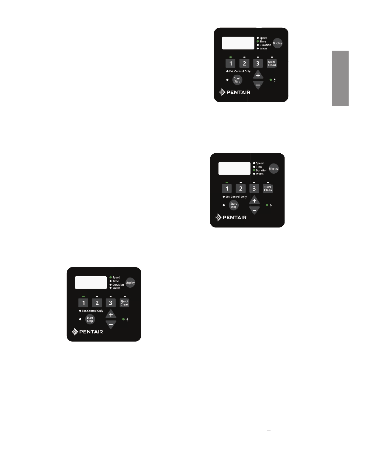
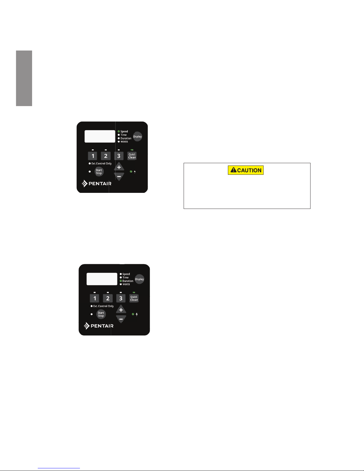
9:00Pm
Figure 7: Activating External Control Only
To activate External Control Only mode:
1. Stop the pump by pressing the Start/Stop button.
2. Activate External Control Only mode by pressing
and holding the Start/Stop button for 3 seconds.
3. If successful the LED next to Ext. Control Only will
illuminate. See Figure 7.
4. The Start/Stop button must be pressed again to
allow the pump to run.
To deactivate External Control Only mode:
1. Stop the pump by pressing the Start/Stop button.
2. Deactivate External Control Only mode by pressing
and holding the Start/Stop button for 3 seconds.
3. If successful the LED next to Ext. Control Only will
turn o. See Figure 7.
4. The Start/Stop button must be pressed again to
allow the pump to run.
OPERATING THE PUMP
Setting the Clock
When the pump is rst plugged in, the clock will blink to
indicate that is has not been set. Any daily schedule set
by the user will be based on this clock setting, so it will
be necessary to set the clock rst.
To Set the Clock:
1. Press and hold the Display button for 3 seconds.
2. Use the “+” and “-” arrows to choose between a 12
or 24 hour time format.
3. Press Display to advance in the Clock Setup menu
4. Use the “+” and “-” arrows to change the time to the
correct time of day. In the 12 hour time format AM/
PM will display in the bottom right corner.
5. Press Display to advance.
6. Use the “+” and “-” arrows to adjust the screen
backlight brightness.
7. Press Display to exit the Clock Setup menu. The
clock is now set.
During a power outage, the drive will retain the clock
setting in memory for as long as 24 hours. If the power
is out longer than 24 hours the clock will have to be set
again. If the drive has lost the user set time, the clock
will continuously blink until the time is reset.
Once the time is reset the clock will stop blinking.
Note: When power is returned to the pump after
a prolonged outage (24+ hours) the clock will
automatically set itself to the Speed 1 start time, blink
and advance. The pump will also run the associated
schedule from that start time.
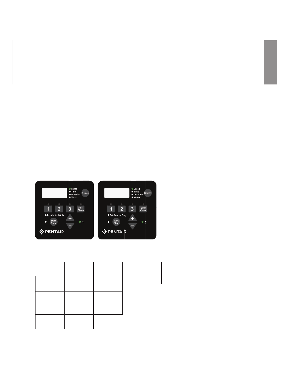
Using the Default Schedule
The default schedule is designed to provide enough
daily turnover to service a typical pool. See Table 2
for default schedule.
Duration
(Hours)
Speed
(RPM)
SPEED 1 2 3000
SPEED 2 10 1400
SPEED 3 2 2200
Table 2: Default Schedule.
Page 11
11
ENGLISH
5. Use the “+” and “-” arrows to adjust the daily start
time for SPEED 1.
6. Press the “1” button again and the display will change
to SPEED 1 duration. The “Duration” parameter LED
will begin to blink. See Figure 10.
7. Use the “+” and “-” arrows to adjust the duration for
SPEED 1 in hours and minutes.
Note: The duration parameter is adjusted in 15 minute
increments.
8. Pressing the “1” button will continue to cycle through
these parameters, but the changes are immediately
saved as they are adjusted.
9. Press the “2” button. The LED above SPEED 2 will
begin to ash and the corresponding parameter LED
will ash while editing.
10. Use the “+” and “-” arrows to adjust the speed in
RPM for SPEED 2.
11. Press the “2” button again and the display will change
to SPEED 2 duration.
Note: SPEEDs 2 and 3 do not have a start time,
as they begin their duration immediately after the
previous SPEED nishes.
12. Use the “+” and “-” arrows to adjust the duration for
SPEED 2 in hours and minutes.
13. Repeat steps 9-12 to program SPEED 3 and QUICK
CLEAN.
Note: Remember that the duration allowed for SPEED
3 will be limited to the remaining time in a 24 hour
day. Any time in the 24 hour day not programmed
into SPEEDs 1-3, the pump will remain in a stationary
state.
[ SPEED 1 + SPEED 2 + SPEED 3 < 24 Hours ]
Custom Schedules
To customize the run schedule for your VS2 Variable
Speed Pump, the pump must be stopped. Be sure that
the Start/Stop button LED is not illuminated.
Programming a Custom Schedule:
Note: When programming, the LED light next to the
parameter (“Speed”, “Time” and “Duration”) you are
setting will blink.
1. Stop the pump if it is running by pressing the Start/
Stop button.
2. Press the “1” button. The LED above the selected
SPEED will begin to blink and the “Speed”
parameter LED will blink while editing. See
Figure 8.
3. Use the “+” and “-” arrows to adjust the speed in
RPM for SPEED 1.
Note: Speed is adjusted up or down by increments
of 10 RPM.
4. Press the “1” button again and the display will
change to SPEED 1 start time. The “Time”
parameter LED will begin to blink. See Figure 9.
3000
Figure 8: Setting Speed
8:00AM
Figure 9: Setting Start Time
2:00
Figure 10: Setting Duration
SPEED 1 is set to begin at 8:00am and run at 3000
RPM for a duration of 2 hours. When SPEED 1 is
complete the pump immediately begins running the
default SPEED 2. SPEED 2 is factory default to 1400
RPM and will last for 10 hours. When SPEED 2 has
completed its run the pump will run SPEED 3 at 2200
RPM for a duration of two hours.
After 14 hours of run time and completing its run of
SPEED 3, the pump will enter a stationary/paused
state for the next 10 hours. The pump will restart at
8:00am the next morning and cycle through the default
schedule again. The pump will continue to run in this
in this manner until a custom schedule is programmed
into the drive by the user.
Note: The Start/Stop button must be pressed, and the
LED lit, for the pump to run.
ENGLISH
Page 12
12
ENGLISH
Note: If the pump has been stopped via the Start/Stop
button, the pump will not run until the pump is turned
back on by the Start/Stop button. If the Start/Stop
LED is illuminated then the pump is on and will run the
programmed schedule.
Operating the Pump While Running
Pressing the Display button will cycle through the current
parameters.
• Speed — current run speed
• Time — current time of day
• Duration — amount of time remaining at
the current run speed
If power is connected to the pump motor, pressing any of the
following buttons referred to in this section could result in the motor starting.
Failure to recognize this could result in personal injury or damage to
equipment.
Speed Priorities (Non-External Control)
For schedule duration settings, SPEEDs are prioritized as
follows: SPEED 1 -> SPEED 2 -> SPEED 3. SPEED 1 is
the highest priority, while SPEED 3 is the lowest.
The drive will not allow a user to program a schedule
of more than 24 hours. When the 24th hour of duration
is programmed it will take time from the lower priority
speeds in order to add them to the SPEED currently
being adjusted.
Example:
Starting Schedule (Before Adjustment)
SPEED 1 duration = 20 hours
SPEED 2 duration = 2 hours
SPEED 3 duration = 2 hours
If the user reprograms SPEED 1 to run for 23 hours,
SPEED 2 (lower priority speed) will automatically
adjust to a 1 hour duration and SPEED 3 (lowest
priority speed) will adjust to a 0 hour duration.
End Schedule (After Adjustment)
SPEED 1 duration = 23 hours
SPEED 2 duration = 1 hour
SPEED 3 duration = 0 hours
Note: If a user wants to have a period of time during the
day when the pump is not running, any of the SPEEDs
can be programmed to 0 RPM. This will cause the pump
to remain stationary/paused throughout the duration of
that SPEED.
14. Press the Start/Stop button and ensure the LED is
lit. The pump is now on and will run the custom userprogrammed schedule.
• Watts — amount of watts currently
being consumed
Pressing any of the Speed Buttons (“1”, “2”, “3”, “Quick
Clean”) while the pump is running will act as temporary
override. It will run the speed and duration that is
programmed for that button. Once completed it will
default back to the appropriate point in the programmed
schedule.
Note: If you adjust the speeds of the schedule while the
pump is running, it will run the adjusted speed for the rest
of the current duration, but will not save the adjustments.
Exception: Speed and Duration adjustments to
QUICK CLEAN will always be immediately saved.
Quick Clean
If running Quick Clean, pressing the “+” or “-” arrows
will change the speed accordingly. Pressing the Quick
Clean button again within 10 seconds of pressing the “+”
or “-” arrows will allow you to adjust the duration of Quick
Clean via the “+” and “-” arrows. These changes will be
saved immediately and are the new defaults for Quick
clean. Pressing the Quick Clean button again will cycle
through the two Quick Clean settings. The pump will exit
out of editing mode if no additional buttons are pressed
within 10 seconds.
If Quick Clean is running and you wish to stop the Quick
Clean prior to the duration being completed you can
press and hold the Quick Clean button for 3 seconds
and the pump will return to the appropriate point in the
programmed schedule.
Some speeds might cause resonance and noise coming
from the pump in specic installations.
This can be solved by slightly modifying the speed.
Page 13
13
ENGLISH
This pump is shipped with Priming mode ENABLED. Unless the Priming settings are changed in the menu, be aware
that the pump will speed up to the priming speed when the pump is powered on for the rst time, and the
start/stop button is pressed.
Before turning the pump ON, be sure the following conditions are met:
1. Open lter air relief valve.
2. Open valves.
3. Pool return is completely open and clear of any blockages.
4. Water in the pump basket.
5. Stand clear of the lter or other pressurized vessels.
DO NOT run the pump dry. If the pump is run dry, the mechanical seal will be damaged and the pump will start leaking.
If this occurs, the damaged seal must be replaced. ALWAYS maintain proper water level in your pool (half way up
skimmer opening). If the water level falls below the skimmer opening, the pump will draw air through the skimmer, losing the prime and
causing the pump to run dry, resulting in a damaged seal. Continued operation in this manner could cause a loss of pressure, resulting
in damage to the pump case, impeller and seal and may cause property and personal injury.
Priming will automatically run when the VS2 Variable
Speed Pump is started from a stopped state, except
when running in Quick Clean mode. Priming will run
at 2850 RPM by default, and will last for 5 minutes.
The drive’s screen will display and cycle through
the following things “PrI - Priming Speed, PrI --
Remaining Time”.
Once priming has begun, the speed can be adjusted
between 3450 and 1700 RPM using the “+” and “-”
arrows. If it is adjusted below 1700 RPM, Priming
mode will be disabled and the pump will immediately
begin to run the scheduled speed.
When priming is disabled and the pump is started
from a stopped state, the screen will display, “PrI
- OFF” for 10 seconds while running the scheduled
speed (See Figure 11). This allows the user time to
enable priming mode by pressing the “+” arrow. If the
user chooses to re-enable priming mode, the pump
will then transition from the scheduled speed to 1700
RPM. The user can increase the priming speed from
1700 RPM by pressing the “+” arrow. The 5 minute
priming countdown timer starts when priming is rst
engaged.
The installer should set the priming speed to be
sucient for priming the pump from a fresh install,
but not so fast that there is a substantial waste of
energy during the 5 minute priming window. The time
the pump needs to achieve prime can change based
on local environmental conditions such as water
temperature, atmospheric pressure, and your pool’s
water level. All of these things should be taken into
consideration when setting the priming speed, however
in most cases the pump will not need to run at 2850
RPM to successfully prime itself.
Please test and verify chosen priming speeds more
than once, letting the water drain from the system in
between each test.
Note: The pump strainer basket should always remain
full to the bottom of the inlet in order to prevent air from
entering the system.
Figure 11: Priming Deactivation
PrI
OFF
Priming
ENGLISH
Page 14
14
ENGLISH
Quick Clean
The VS2 Variable Speed Pump is equipped with a Quick Clean
feature, which can be engaged to temporarily run at higher or
lower speeds ranging between 300 to 3450 RPM. Once the
Quick Clean duration has elapsed, the pump will automatically
return to the programmed schedule.
Programming Quick Clean:
1. Stop the pump if it is running by pressing the
Start/Stop button.
2. Press the Quick Clean button. The LED
above the Quick Clean button and the “Speed”
parameter LED will ash while editing. See
Figure 12.
3. Use the “+” and “-” arrows to adjust the speed in
RPM for Quick Clean.
4. Press the Quick Clean button again and the
display will change to Quick Clean duration. The
“Duration” parameter LED will ash while editing.
See Figure 13.
Note: The Quick Clean feature does not have a
start time.
5. Use the “+” and “-” arrows to adjust the duration
in hours and minutes for Quick Clean.
6. Press the Start/Stop button and ensure the LED
is illuminated. The pump is now on and will run
the speed and duration set for Quick Clean.
Note: When the Quick Clean duration ends, the pump resumes
the 24 hour schedule at the point where it normally would be
running at that time. The Quick Clean duration will not affect
the start or stop times of the 24 hour schedule. For example, if
Quick Clean runs during a period overlapping with a later part of
SPEED 1 and an early part of SPEED 2, the start time of SPEED
3 is not affected.
Note: Pressing/Holding Quick Clean key for more than three (3)
seconds will cancel Quick Clean mode.
Note: During the Quick Clean mode, the pump will not start with
the priming sequence.
Note: It is recommended that you do not set the Quick Clean
duration to 0 HRS. Setting the Quick Clean duration to 0 HRS
will not allow you to change the duration setting while the motor
is running. The motor will have to be stopped in order to change
the Quick Clean settings if the duration is set to 0 HRS.
Keypad Lockout
The VS2 Variable Speed Pump user interface has a Keypad Lockout
feature to prevent unwanted changes to the settings. When locked,
the keypad will only accept input from pressing the Display button
to cycle the displayed information on the screen and input to stop
the motor from a press of Start/Stop button.
The keypad can be locked by pressing and holding the “1” button
and the Quick Clean button at the same time for at least three
seconds. “Loc On” will be displayed if successful.
To unlock the keypad press and hold the “1” button and the Quick
Clean button at the same time for at least three seconds. “Loc OFF”
will be displayed if successful.
Note: While operating in Keypad Lockout mode the motor can still
be stopped by pressing the Start/Stop button. However, the motor
can not be started again until the user unlocks the keypad.
Key lockout will not prevent the motor from being stopped by pressing
the Start/Stop button. It will then be unable to be restarted until the
keypad has been unlocked. If the motor is operating in Keypad Lockout
mode, and being controlled through external controls, it can only run
when the Start/Stop LED is illuminated.
3450
Figure 12: Setting Speed for Quick Clean
2:00
Figure 13: Setting Duration for Quick Clean
Page 15
15
ENGLISH
Factory Reset
The drive can be reset to factory settings if necessary. A
Factory Reset will wipe out all of the saved user settings
that have been programmed, except for the time of day.
Be sure that it is necessary before performing a Factory
Reset, as the results are immediate.
To perform a Factory Reset:
1. Stop the pump if necessary by pressing the Start/
Stop button.
2. Record all of the custom schedule settings using
Table 3. You can find these setting by pressing
the “1”, “ 2”, “ 3”, and “Quick Clean” buttons and
cycling through all the screens. Also write down
the Priming Speed.
3. Press and hold the “1”, “ 2”, “ 3”, and “Quick Clean”
buttons for 3 seconds.
4. The screen will display “FACt rSt” if factory reset
is successful. See Figure 14.
5. Be sure to reprogram the schedule and priming
speed after the factory reset. The pump must be
turned back on with the Start/Stop button before it
will run again. The pump will run the programmed
schedule upon initial start-up.
Note: Factory Reset can not be performed from a
Keypad Lockout state.
Speed
(RPM)
Duration
(Hours)
Start Time
(Time Clock)
SPEED 1
SPEED 2
SPEED 3
QUICK
CLEAN
Priming
Speed
Table 3: User Programmed Schedules
Figure 14: Drive Factory Reset
FACt
rSt
ENGLISH
Page 16
16
ENGLISH
MAINTENANCE
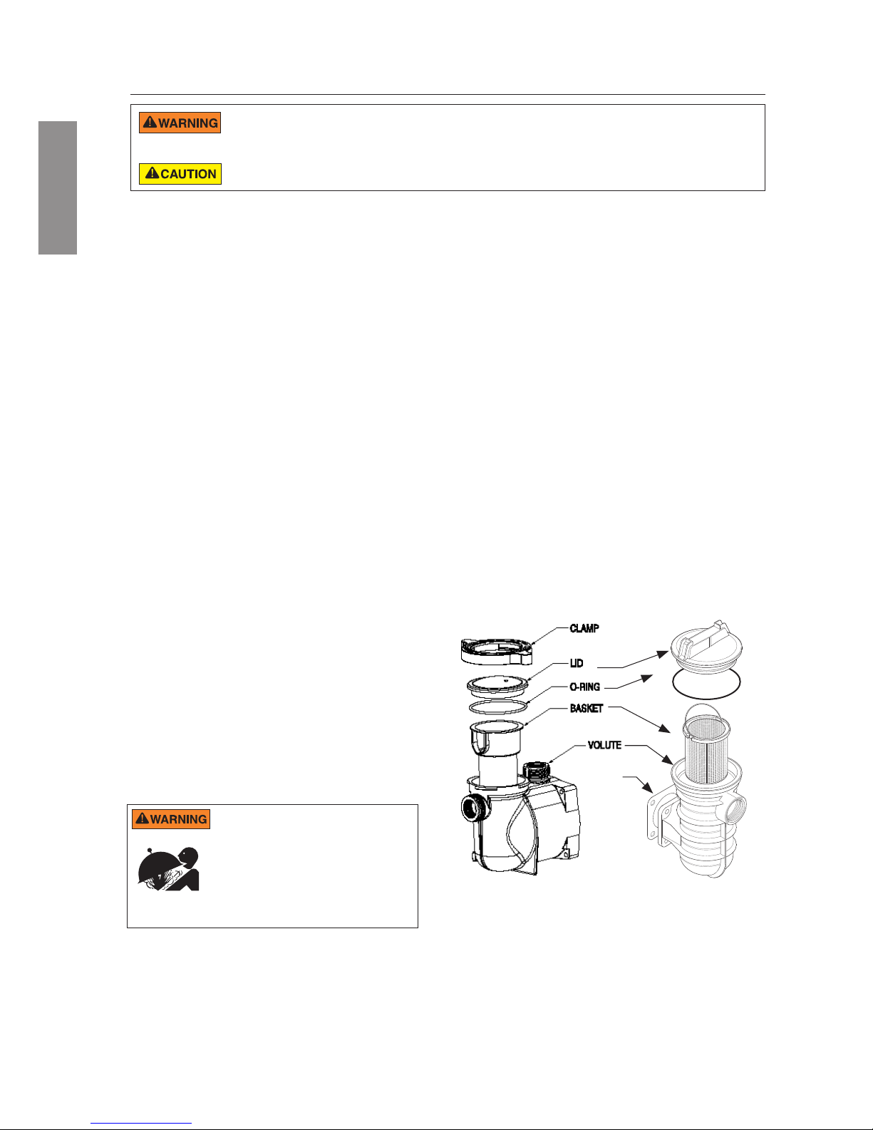
Pump Strainer Basket
The pump strainer basket (or ‘strainer pot’, ‘hair and lint
pot’), is located in front of the volute. Inside the chamber
is the basket which must be kept clean of leaves and
debris at all times. View basket through the ‘See Through
Lid’ to inspect for leaves and debris.
Regardless of the length of time between lter cleaning,
it is most important to visually inspect the basket at
least once a week.
DO NOT open the strainer pot if VS2 Variable Speed Pump fails to prime or if pump has been operating without water in the strainer
pot. Pumps operated in these circumstances may experience a build up of vapor pressure and may contain scalding hot water.
Opening the pump may cause serious personal injury. In order to avoid the possibility of personal injury, make sure the suction and
discharge valves are open and strainer pot temperature is cool to touch, then open with extreme caution.
To prevent damage to the pump and for proper operation of the system, clean pump strainer and skimmer baskets regularly.
Cleaning the Pump Strainer Basket
1. Press the Start/Stop button to stop the pump and
turn o the pump at the circuit breaker.
2. Relieve pressure in the system by allowing the water
to cool.
3. Gently tap the clamp in a counter-clockwise direction
to remove the clamp and lid.
4. Remove debris and rinse out the basket. Replace
the basket if it is cracked.
5. Put the basket back into the housing. Be sure to align
the notch in the bottom of the basket with the rib in
the bottom of the volute.
6. Fill the pump pot and volute up to the inlet port with
water.
7. Clean the cover, O-ring, and sealing surface of the
pump pot. Note: It is important to keep the lid O-ring
clean and well lubricated.
8. Reinstall the lid by placing the lid on the pot. Be sure
the lid O-ring is properly placed. Seat the clamp and
lid on the pump then turn clockwise until the handles
are horizontal.
9. Turn the power on at the house circuit breaker. Reset
the pool time clock to the correct time, if applicable.
10. Open the manual air relief valve on top of the lter.
11. Stand clear of the lter. Start the pump.
12. Bleed air from the lter until a steady stream of water
comes out. Close the manual air relief valve.
THIS SYSTEM OPERATES UNDER HIGH
PRESSURE. When any part of the circulating
system (e.g., Lock Ring, Pump, Filter, Valves, etc.)
is serviced, air can enter the system and become
pressurized. Pressurized air can cause the lid to
separate which can result in serious injury, death,
or property damage. To avoid this potential hazard,
follow above instructions.
Winterizing
You are responsible for determining when freezing
conditions may occur. If freezing conditions are
expected, take the following steps to reduce the risk of
freeze damage. Freeze damage is not covered under
warranty.
To prevent freeze damage, follow the procedures below:
1. Press the Start/Stop button to stop the pump and
shut o electrical power for the pump at the circuit
breaker.
2. Drain the water out of the pump housing by
removing the two thumb-twist drain plugs from the
housing. Store the plugs in the pump basket.
3. Cover the motor to protect it from severe rain, snow
and ice.
Note: Do not wrap motor with plastic or other air tight
materials during winter storage. The motor may be
covered during a storm, winter storage, etc., but never
when operating or expecting operation.
Note: In mild climate areas, when temporary freezing
conditions may occur, run your ltering equipment all
night to prevent freezing.
Strainer Pot Assembly
GASKET
Page 17
17
Electric Motor Care
Protect from heat
1. Shade the motor from the sun.
2. Any enclosure must be well ventilated to prevent
overheating.
3. Provide ample cross ventilation.
Protect against dirt
1. Protect from any foreign matter.
2. Do not store (or spill) chemicals on or near the motor.
3. Avoid sweeping or stirring up dust near the motor
while it is operating.
4. If a motor has been damaged by dirt it may void the
motor warranty.
5. Clean the lid and clamp, O-ring, and sealing surface
of the pump pot.
Protect against moisture
1. Protect from splashing or sprayed water.
2. Protect from extreme weather such as ooding.
3. If motor internals have become wet - let them dry
before operating. Do not allow the pump to operate if
it has been ooded.
4. If a motor has been damaged by water it may void
the motor warranty.
SERVICING
DO NOT run the pump dry. If the pump is run dry, the mechanical seal will be damaged and the pump will start leaking. If this occurs,
the damaged seal must be replaced. ALWAYS maintain proper water level. If the water level falls below the suction port, the pump will
draw air through the suction port, losing the prime and causing the pump to run dry, resulting in a damaged seal. Continued operation in this manner could
cause a loss of pressure, resulting in damage to the pump case, impeller and seal and may cause property damage and personal injury.
Always disconnect power to the VS2 Variable Speed Pump at the circuit breaker and disconnect the
communication cable before servicing the pump. Failure to do so could result in death or serious injury to
service people, users or others due to electric shock. Read all servicing instructions before working on the pump.
DO NOT open the strainer pot if pump fails to prime or if pump has been operating without water in the strainer pot. Pumps operated
in these circumstances may experience a build up of vapor pressure and may contain scalding hot water. Opening the pump may
cause serious personal injury. In order to avoid the possibility of personal injury, make sure the suction and discharge valves are open and strainer pot
temperature is cool to touch, then open with extreme caution.
Be sure not to scratch or mar the polished shaft seal faces; seal will leak if faces are damaged. The polished and lapped faces
of the seal could be damaged if not handled with care.
ENGLISH
Pump Disassembly
All moving parts are located in the rear sub-assembly
of this pump.
Tools required:
• 1/4 inch socket or open end wrench.
• 3/8 inch socket or open end wrench.
• 9/16 inch open end wrench.
• 1/4 inch Allen Key
• Flat blade screwdriver.
To remove and repair the motor subassembly, follow
the steps below:
1. Press the Start/Stop button to stop the pump and
turn o the pump circuit breaker at the main panel.
2. Drain the pump by removing the drain plugs.
3. Remove the 4 bolts that hold the main pump body
(strainer pot/volute) to the rear sub-assembly.
4. GENTLY pull the two pump halves apart, removing
the rear sub-assembly.
5. Remove the three hex head screws holding the
diuser in position.
6. Hold the impeller securely in place and remove the
impeller lock screw by using a at blade screwdriver
or wrench. The screw is a left-handed thread and
loosens in a clockwise direction.
7. To unscrew the impeller from the shaft, insert a 1/4
inch Allen key into the center of the motor fan cover
and twist the impeller counter-clockwise.
8. Remove the four bolts from the seal plate to the
motor using a 9/16 inch wrench.
9. Place the seal plate face down on a at surface
and tap out the ceramic seal.
10. Clean the seal plate, seal housing, and the motor
shaft.
Shaft Seal Replacement
The Shaft Seal consists primarily of two parts, a
rotating member and a ceramic seal.
The pump requires little or no service other than
reasonable care, however, a Shaft Seal may
occasionally become damaged and must be replaced.
Note: The polished and lapped faces of the seal could be
damaged if not handled with care.
ENGLISH
Page 18
18
Restart Instructions
If VS2 Variable Speed Pump is installed below the
water level of the pool, close return and suction lines
prior to opening hair and lint pot on pump. Make sure
to re-open valves prior to operating.
Priming the Pump
The pump strainer pot must be lled with water
before the pump is initially started.
Follow these steps to prime the pump:
1. Remove the pump lid plastic clamp. Remove the
pump lid.
2. Fill the pump strainer pot with water.
3. Reassemble the pump cover and plastic clamp
onto the strainer pot. The pump is now ready to
prime.
4. Open the air release valve on the lter, and stand
clear of the lter.
5. Turn on the power to the pump.
6. Press the Start/Stop button on the drive keypad.
If the pump is currently scheduled to run it will
start.
Note: If the pump is not schedule to start, press
a Speed button to begin a manual override that
will start the pump.
7. When water comes out of the air release valve,
close the valve. The system should now be free
of air and recirculating water to and from the pool.
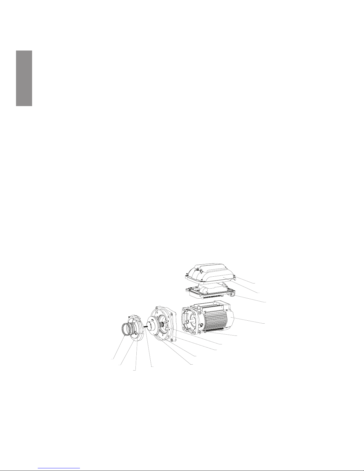
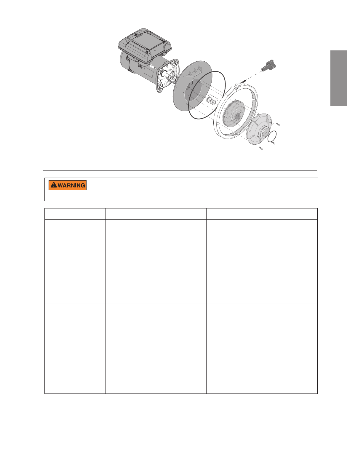
DIFFUSER
DIFFUSER SCREWS (3X)
DIFFUSER SEAL
IMPELLER
IMPELLER SET SCREW
(REVERSE THREAD)
SEAL PLATE O-RING
SEAL PLATE
MECHANICAL SEAL
MOTOR TO SEALPLATE
HARDWARE (4X)
MOTOR
DRIVE
DRIVE COVER
DRIVE COVER TO
DRIVE SCREWS (4X)
Pump Reassembly
1. When installing the replacement seal into the seal
plate, use soapy water to wet the rubber boot
before pressing it into the seal plate.
2. Remount the seal plate to the motor.
3. Before installing the rotating portion of the seal on
the motor shaft, wet the motor shaft with soapy
water and slide the seal onto the motor shaft.
Ensure that the carbon face contacts the ceramic
face of the stationary seat. Press the seal into
the seal plate with your thumbs and wipe o the
ceramic with a clean cloth.
4. Screw impeller onto the motor shaft (clockwise to
tighten).
5. Screw in the impeller lock screw (counterclockwise to tighten).
Note: Insert a 1/4” hex Allen wrench into the
motor shaft through the hole in the rear motor
fan cover. This will prevent the motor shaft from
rotating and you screw in the impeller lock screw.
6. Remount the diuser onto the seal plate. Make
sure the plastic pins and holding screw inserts
are aligned.
7. Grease the diuser quad ring and seal plate
O-ring prior to reassembly.
8. Assemble the motor sub-assembly to the strainer
pot-pump body. Tighten the bolts until all 4 bolts
are in place and nger tightened.
9. Fill the pump with water.
10. Reinstall the pump lid and plastic clamp; see the
next section, ‘Restart Instructions’.
11. Re-prime the system.
ENGLISH
SuperMax® VS2 Motor Assembly
Page 19
19
TROUBLESHOOTING
Problem Possible Cause Corrective Action
Pump failure.
Pump will not prime - Air leak, too much air.
Pump will not prime - Not enough water.
Pump stainer gasket is clogged.
Pump strainer gasket is defective.
Check suction piping and valve glands on any suction
gate valves. Secure lid on pump strainer pot and be
sure lid gasket is in place. Check water level to be
sure skimmer is not drawing air.
Be sure the suction lines, pump, strainer, and pump
volute are full of water. Be sure valve on suction line
is working and open (some systems do not have
valves). Check water level to make sure water is
available through skimmer.
Clean pump strainer pot.
Replace gasket.
Reduced capacity and/
or head.
Air pockets or leaks in suction line.
Clogged impeller.
Pump strainer clogged.
Check suction piping and valve glands on any suction
gate valves. Secure lid on pump strainer pot and be
sure lid gasket is in place. Check water level to be
sure skimmer is not drawing air.
Turn o electrical power to the pump.
Disassemble (see page 14, ‘Pump Disassembly’)
Clean debris from impeller. If debris cannot be
removed, complete the following steps:
1. Remove left hand thread anti-spin bolt and o-ring.
2. Remove, clean, and reinstall impeller.
Reassemble (see page 15, ‘Pump Reassembly’)
Clean suction trap.
Diagnosing certain symptoms may require close interaction with, or in close proximity to, components that are energized with
electricity. Contact with electricity can cause death, personal injury, or property damage. When trouble shooting the pump,
diagnostics involving electricity should be cared for by a licensed professional.
ENGLISH
S5P2R™-VS2 Motor Assembly
ENGLISH
Page 20

20
Troubleshooting (Cont.)
Pump fails to start.
Mains Voltage is not present
Pump shaft is locked
Pump shaft is damaged
1. Replace fuse, reset breaker/GFCI.
2. Tighten mains wire connections.
Check if the pump can be rotated by hand and
remove any blockage.
Replace pump.
Pump runs then stops.
Over temperature FAULT
Over current FAULT
Check that back of pump is free from dirt and debris.
Use compressed air to clean.
Pump will automatically restart after one (1) minute.
Pump is noisy.
Debris in contact with fan
Debris in strainer basket
Loose mounting
Check that back of pump is free from dirt and debris.
Use compressed air to clean.
Clean strainer basket.
Check that mounting bolts of pump and pump are
tight.
Problem Possible Cause
Corrective Action
Pump runs without ow.
Impeller is loose
Air leak
Clogged or restricted plumbing
Check that pump is spinning by looking at fan on back
of SuperMax VS2 Variable Speed Pump. If so, check
that pump impeller is correctly installed.
Check plumbing connections and verify they are tight.
Check for blockage in strainer or suction side piping.
Checked for blockage in discharge piping including
partially closed valve or dirty pool lter.
ENGLISH
Page 21

21
Errors and Alarms
If an alarm is triggered the drive’s LCD screen will display the fault code text and the VS2 Variable Speed Pump
will stop running. Disconnect power to the pump and wait until the keypad LEDs have all turned o. At this point,
reconnect power to the pump. If the error has not cleared then proper troubleshooting will be required. Use the
error description table below to begin troubleshooting.
21 – Communication Link between the HMI and Motor control has been lost: Check the jacketed wire on the
back side of the keypad inside the drive top cover. Ensure that the 5 pin connector is properly plugged into the
socket and that there is no damage to the cable.
1A – Power Module over current detected: If this error displays multiple times, then there may be a problem
with the pump’s rotating assembly. Please disassemble the pump and investigate to see if there is a problem with
the impeller or mechanical seal. See page 14 “Pump Disassembly” for instructions for disassembling the pump.
OF – Absolute AC Under Voltage Detected: This indicates that the supply voltage has dropped below the
operating range of 99v. This could be caused by normal voltage variation and will clear itself. Otherwise there
could be excess voltage sag caused by improper installation or improper supply voltage.
17, 1b, 02, 08, 04, 06, 09, 0A – Internal Errors: These errors can occur based on operating conditions and
the UL 60730 required self-diagnostic safety software. If they do not clear after multiple restart attempts the
drive should undergo a hard power cycle. Disconnect main power by turning o the breaker long enough for the
keypad LEDs to turn o. After power is reconnected if one of these errors continues to reappear, the drive may
need service.
Fault Code Description
Communication link between HMI and motor control has been lost
Power Module over current detected
Phase Current Offset out of range
Phase Current Imbalance detected
Absolute AC under voltage detected
Absolute Phase current limit exceeded
Absolute Diode Bridge temperature limit exceeded
Absolute Power Module temperature limit exceeded
Absolute Power Factor Correction (PFC) temperature limit exceeded
DC bus over voltage detected
DC bus under voltage detected
ENGLISH
Overall Ratings
Input Voltage 115-230 Vrms nominal
Input Current 13.2/12.0-11.5 A
Input Frequency Single phase, 50 or 60 Hz
Control Terminals 18-30V AC (24V AC+/- 20%) or
9-30V DC (12/24V DC +/- 20%)
Maximum Continuous Load 2.0 THP (Total Horse Power)
Speed Range 300 - 3450 RPM
Environmental Rating NEMA Type 3
Ambient Conditions
Storage -40ºC to +85ºC (-40ºF to +185°)
Operating 0ºC to +50ºC (+32°F to +122°F)
Humidity Relative 0 to 95 % non-condensing
Pump Specications
ENGLISH
Page 22
22
FRANCAIS
REMARQUE IMPORTANTE
Ce guide procure des instructions relatives à l'installation et au
fonctionnement de la pompe à vitesse variable. Consultez Pentair
si vous avez des questions concernant cet équipement.
A l'attention de l'installateur: ce guide présente une série
d'instructions importantes concernant l'installation, le fonctionnement et
l’utilisation sans risque de ce produit. Ces informations doivent être transmises
au propriétaire et/ou à l'opérateur de cet équipement après l'installation ou
laissées sur ou près de la pompe.
A l'attention de l'utilisateur: ce manuel contient d'importantes informations
qui vous aideront à utiliser et entretenir ce produit. Veuillez le conserver pour
pouvoir vous y reporter ultérieurement. Avertissements et instructions de
sécurité pour Pentair Aquatic Systems. Pompes et autres produits connexes
disponibles sur :
http://www.pentairpool.com/pool-owner/safety-warnings/ pour des copies
supplémentaires gratuites des présentes instructions.
LISEZ ET SUIVEZ TOUTES LES INSTRUCTIONS
SAUVEGARDEZ CES INSTRUCTIONS
Voici le symbole d'alerte de sécurité. Lorsque
vous apercevez ce symbole dans votre système
ou sur ce manuel, recherchez un des mots clés
suivants et soyez vigilant au risque de dommages
corporels.
Avertissements relatifs à des risques pouvant
potentiellement provoquer la mort, des
dommages corporels ou matériels graves s'ils
sont ignorés.
Avertissements relatifs à des risques susceptibles
de provoquer la mort, des dommages corporels
ou matériels graves s'ils sont ignorés.
Avertissements relatifs à des risques pouvant
potentiellement ou susceptibles de provoquer
des dommages ou matériels mineurs s'ils
sont ignorés.
NOTE indique des instructions spéciales non liées à des risques.
Lisez attentivement et respectez toutes les instructions de sécurité gurant
dans ce manuel et sur l'équipement. Gardez les étiquettes de sécurité en
bon état et remplacez-les si elles manquent ou sont abimées.
Lors de l'installation et de l'utilisation de cet équipement électrique, prenez
toujours des précautions de sécurité élémentaires, notamment :
N'autorisez pas les enfants à utiliser ce produit.
RISQUE DE DÉCHARGE ÉLECTRIQUE. Raccordez seulement à un circuit
dérivé protégé par un disjoncteur-détecteur de fuites
à la terre (GFCI). Contactez un électricien qualié si
vous ne pouvez pas vérier que le circuit est protégé
par un GFCI.
L'unité doit seulement être reliée à un circuit d'alimentation
protégé par un disjoncteur-détecteur de fuites à la terre
(GFCI). Ce GFCI doit être fourni par l'installateur et testé
régulièrement. Pour tester le GFCI, appuyez sur le bouton de test. Le GFCI doit
interrompre l'alimentation de courant. Appuyez sur le bouton de RAZ. L'alimentation
électrique doit être rétablie. Si le GFCI ne fonctionne pas comme cela, il est
défectueux. Si le GFCI interrompt l'alimentation de la pompe sans devoir appuyer
sur le bouton de test, un courant à la terre circule, indiquant la possibilité d'un choc
électrique. N'utilisez pas cette pompe. Débranchez la pompe et faites-la réparer
par un représentant de service qualié avant de l'utiliser à nouveau.
Cette pompe est destinée à être utilisée
avec des piscines à installation permanente
et peut également être utilisée avec des
bains à remous et des spas le cas échéant. Ne pas utiliser avec des piscines
démontables. Une piscine installée de manière permanente est construite
dans le sol, sur le sol ou dans un bâtiment, et ne peut pas être démontée pour
être rangée. Une piscine démontable est conçue de manière à pouvoir être
démontée rapidement en vue de son rangement et remontée dans son état
d'intégrité initial.
Avertissements généraux
• N'ouvrez jamais l'intérieur de l'enceinte du moteur d'entraînement. Même
lorsque l'unité n'est pas alimentée, une batterie de condensateurs contient
du courant 230 V CA.
• La pompe n'est pas submersible.
• La pompe autorise des débits élevés ; procéder avec précaution lors
de l'installation et de la programmation pour limiter le potentiel de
performances des pompes avec de l'équipement ancien ou douteux.
• Les exigences du code de connexion électrique diffèrent d'un État à
l'autre. Installez l'équipement conformément au Code National Électrique
en vigueur et à tous les codes et règlements locaux d'application.
• Avant une intervention sur la pompe, mettez la pompe HORS tension
en débranchant la pompe du secteur.
• L'appareil n'est pas conçu pour être utilisé par des personnes (y compris
des enfants) ayant des aptitudes physiques, sensorielles ou mentales
réduites ou manquant d'expérience et de connaissance, sauf si elles
sont supervisées ou ont reçu des instructions concernant l'utilisation
de l'appareil par une personne responsable de leur sécurité.
• Une liaison équipotentielle sufsante (min. 4.5mm2 recommandé),
conformément à la réglementation locale, est obligatoire sur tous
les composants métalliques de la piscine, y compris la pompe de
piscine. Ceci est nécessaire pour la sécurité électrique, ainsi qu’à
la réduction du risque de corrosion.
NE PAS SUIVRE TOUTES LES CONSIGNES ET TOUS
LES AVERTISSEMENTS PEUT CAUSER DES
BLESSURES CORPORELLES GRAVES, VOIRE LA
MORT. SEUL UN PROFESSIONNEL D’ENTRETIEN DE PISCINE QUALIFIE
PEUT INSTALLER ET ENTRETENIR CETTE POMPE. LES INSTALLATEURS,
OPÉRATEURS ET PROPRIÉTAIRES DE PISCINE DOIVENT LIRE CES
AVERTISSEMENTS ET TOUTES LES CONSIGNES DU MANUEL DU
PROPRIÉTAIRE AVANT D’UTILISER LA POMPE. CES AVERTISSEMENTS
ET LE MANUEL DU PROPRIÉTAIRE DOIVENT ÊTRE LAISSES AU
PROPRIÉTAIRE DE LA PISCINE.
RISQUE D'ASPIRATION : RESTEZ ÉLOIGNÉ(E) DE
L’ÉVACUATION PRINCIPALE ET DE TOUTES LES
SORTIES D'ASPIRATION !
CETTE POMPE PRODUIT DES NIVEAUX ÉLEVÉS D'ASPIRATION ET
CRÉE UNE DÉPRESSION PUISSANTE AU NIVEAU DE L’ÉVACUATION
PRINCIPALE AU FOND DE L'EAU. CETTE ASPIRATION EST SI FORTE
QU'ELLE PEUT PIÉGER LES ADULTES OU LES ENFANTS SOUS L'EAU
S’ILS S’APPROCHENT D'UNE ÉVACUATION OU D'UN COUVERCLE OU
D'UNE GRILLE D’ÉVACUATION CASSE(E) OU DESSERRE(E).
RISQUE DE CHOC ÉLECTRIQUE OU
D’ÉLECTROCUTION : LES POMPES NÉCESSITENT
UNE HAUTE TENSION QUI PEUT PROVOQUER
DES CHOCS, DES BRULURES, VOIRE LA MORT.
AVANT DE TRAVAILLER SUR UNE POMPE ! Toujours
débrancher le courant de la pompe de piscine au
niveau du disjoncteur de la pompe avant d'intervenir
sur la pompe. Tout manquement à cette obligation est
susceptible d'entraîner la mort ou d'occasionner des
lésions corporelles graves aux utilisateurs de la piscine,
aux installateurs ou à d'autres personnes en raison du
risque d'électrocution.
L'UTILISATION DE COUVERCLES NON AUTORISES OU LA PERMISSION
D'UTILISER LA PISCINE OU LE SPA LORSQUE LES COUVERCLES SONT
FISSURES OU CASSES PEUT PIÉGER LE CORPS OU UN MEMBRE, ENTRAINER UN ENCHEVÊTREMENT DES CHEVEUX, UNE EVISCERATION ET/OU
PROVOQUER LA MORT.
L'aspiration d'une évacuation ou d'une sortie peut provoquer :
Coincement d'un membre : si un membre est aspiré ou coincé dans une
ouverture, entrainant un piège mécanique ou un gonement. Ce risque est
présent si un couvercle d'évacuation est manquant, cassé, desserré, ssuré
ou sécurisé de manière incorrecte.
AVERTISSEMENTS ET CONSIGNES DE SECURITE IMPORTANTS DE LA POMPE
Page 23
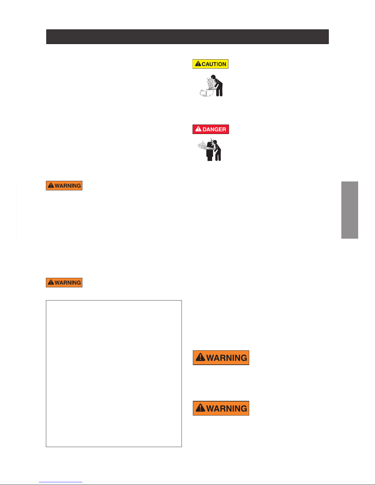
23
FRANCAIS
Coincement de cheveux : si les cheveux sont enchevêtrés ou coincés
dans le couvercle d'évacuation, piégeant par conséquent le nageur sous
l'eau. Ce risque est présent si le débit du couvercle est trop faible pour la
ou les pompe(s).
Coincement du corps : si une partie du corps est maintenue contre le couvercle
d'évacuation piégeant par conséquent le nageur sous l'eau. Ce risque est
présent si le couvercle d'évacuation est manquant, cassé ou si le débit n'est
pas assez élevé pour la ou les pompe(s).
Evisceration/éventrement : quand une personne s'assoit sur une piscine
ouverte (particulièrement les pataugeoires pour enfant) ou sur la sortie du spa
et si l'aspiration est appliquée directement sur les zones intestinales, causant
des blessures graves. Ce risque est présent si un couvercle d'évacuation est
manquant, desserré, ssuré ou sécurisé de manière incorrecte.
Coincement mécanique : quand des bijoux, un maillot de bain, des décorations pour cheveux, des doigts, des orteils ou des articulations sont pris dans
l'ouverture d'une sortie ou d'un couvercle d'évacuation. Ce risque est présent
si un couvercle d'évacuation est manquant, cassé, desserré, ssuré ou sécurisé
de manière incorrecte.
TOUTES LES TUYAUTERIES D'ASPIRATION DOIVENT ÊTRE INSTALLÉES
CONFORMÉMENT AUX DERNIERS CODES, NORMES ET DIRECTIVES
NATIONAUX ET LOCAUX EN VIGUEUR POUR LES PISCINES, LES SPAS
ET LES JACUZZIS.
POUR MINIMISER LES RISQUES DE BLESSURES
PAR PIÈGE D'ASPIRATION :
• Les couvercles d'aspiration doivent être installés à au moins 1 mètre
l'un de l'autre, du point le plus proche au point le plus proche.
• Inspectez régulièrement tous les couvercles pour vérier la présence
de ssures, de dommages ou d'effritements avancés.
• Si un couvercle est détaché, ssuré, endommagé, cassé ou manquant,
remplacez-le par un couvercle certié correspondant.
• Remplacez les couvercles d’évacuation si nécessaire. Les couvercles
d'évacuation se détériorent avec le temps en raison de l'exposition à
la lumière du soleil et des conditions météorologiques.
• Ne mettez pas les cheveux, les membres ou le corps à proximité
d’un couvercle d’aspiration, de l'évacuation ou la sortie d'une piscine.
• Désactivez les sorties d'aspiration et recongurez-les en entrées
de retour.
Un commutateur de coupure d'urgence clairement
étiqueté pour la pompe doit être placé dans un endroit
évident, facilement accessible. Assurez-vous que les
utilisateurs savent où il se trouve et comment l'utiliser en cas d'urgence.
La "Virginia Graeme Baker (VGB) Pool and Spa Safety Act" instaure de
nouvelles exigences pour les propriétaires et opérateurs de piscines et
de spas à vocation commerciale.
Les piscines ou spas à vocation commerciale construits à partir du 19
décembre 2008 utiliseront :
(A) un système d'évacuation principale multiple sans capacité d'isolation
avec des couvercles pour ouvertures d'aspiration, conformes à l'"ASME/
ANSI A112.19.8a Suction Fittings for Use in Swimming Pools, Wading Pools,
Spas, and Hot Tubs" et :
(i) un système d'anti-attrapement de sécurité (SVRS) conforme à "ASME/
ANSI A112.19.17 Manufactured Safety Vacuum Release systems
(SVRS) for Residential and Commercial Swimming Pool, Spa, Hot
Tub, and Wading Pool Suction Systems" et/ou "ASTM F2387 Standard
Specication for Manufactured Safety Vacuum Release Systems (SVRS)
for Swimming pools, Spas and Hot Tubs" ou
(ii) un système de limite d'aspiration correctement conçu et testé ou
(iii) un système d'arrêt automatique de la pompe.
Les piscines et spas à vocation commerciale, construits avant le 19
décembre 2008, avec une sortie d'aspiration immergée utiliseront un
couvercle pour sortie d'aspiration conforme à ASME/ANSI A112.19.8a
et au choix :
(A) un SVRS conforme à ASME/ANSI A112.19.17 et/ou ASTM F2387, ou
(B) un système de limite d'aspiration correctement conçu et testé ou
(C) un système d'arrêt automatique de la pompe ou
(D) des sorties immergées désactivées ou
(E) des sorties d'aspiration seront recongurées en entrées de retour.
Pour l'installation de commandes électriques sur le coussin d'équipements
(commutateurs ON/OFF, temporisateurs et centre de charge d'automatisation)
Les commandes électriques comme les interrupteurs
marche/arrêt, les timers et les systèmes de commande,
devraient être installées pour permettre à la pompe ou au
ltre de fonctionner (démarrage, arrêt ou entretien) sans
devoir mettre une partie du corps sur ou à proximité du
couvercle du pré-ltre de la pompe, du couvercle du ltre
ou de la fermeture de la vanne. Une telle installation devrait
offrir à l'utilisateur assez de place pour rester éloigné du ltre
et de la pompe pendant le démarrage, l'arrêt ou l'entretien
du ltre système.
Pentair Water Pool and Spa
®
IMPORTANT SAFETY INSTRUCTIONS
For Installation of Electrical Controls at Equipment Pad
(ON/OFF Switches, Timers and Aut omation Load Center)
Install all electrical controls at equipment pad, such as on/off
switches, timers, and control systems, etc. to allow the
operation (startup, shut-down, or servicing) of any pump or
filter so the user does not place any portion of his/her body
over or near the pump strainer lid, filter lid or valve closures.
This installation should allow the user enough space to stand
clear of the filter and pump during system start-up, shut down
or servicing of the system filter.
®
PRESSION DANGEREUSE : ÉLOIGNEZ-VOUS DE
LA POMPE ET DU FILTRE PENDANT LE DÉMARRAGE.
Les systèmes de circulation fonctionnent sous haute
pression. En cas d’entretien de n’importe quelle pièce
du système de circulation (par exemple, bague de
retenue, pompe, ltre, vanne etc.), l'air peut entrer dans
le système et être pressurisé. L’air sous pression peut
séparer violemment le couvercle du boîtier de la pompe, le couvercle du ltre et les vannes, causant des blessures graves voire la
mort. Le couvercle de la bouteille du ltre et le couvercle du pré-ltre doivent être
sécurisés pour empêcher toute séparation violente. Restez éloigné du système
de circulation lors de la mise en marche ou du démarrage de la pompe.
Avant l'entretien de l'équipement, notez la pression du ltre. Vériez que toutes
commandes sont positionnées pour garantir que le système ne se mette pas
par inadvertance en marche pendant l'entretien. Coupez le courant de la
pompe. IMPORTANT : mettez la vanne de purge d'air manuelle du ltre en
position ouverte et attendez que la pression du système s'évacue.
Avant le démarrage du système, ouvrez entièrement la vanne de purge d'air
manuelle et mettez toutes les vannes du système en position "ouverte" pour
permettre à l'eau de circuler librement à partir et en direction du réservoir.
Restez éloigné de l'équipement et démarrez la pompe.
IMPORTANT : ne fermez pas la vanne de purge d'air manuelle avant que toute
la pression soit évacuée et qu'un ux constant d'eau apparaisse. Observez la
jauge de pression du ltre et vériez qu’elle n’est pas supérieure aux conditions
préalables à l’entretien.
Informations d'installation générales
• Tous les travaux doivent être effectués par un électricien qualié, et
doivent être conformes à tous les codes nationaux, régionaux et locaux.
• Prévoir un drainage du compartiment des composants électriques.
• Ces instructions contiennent des informations valables pour une variété de
modèles de pompes. Par conséquent, certaines instructions peuvent ne
pas s'appliquer à un modèle spécique. Tous les modèles sont destinés à
être utilisés dans des applications pour piscines. La pompe ne fonctionnera
correctement que si elle est justement dimensionnée pour l'application
spécique et correctement installée.
• Pour empêcher la circulation d‘eau dans le mauvais sens et le desserement
de la turbine, l‘installation d‘une vanne anti-retour après la pompe est
vivement conseillée.
Les pompes mal dimensionnées ou
installées, ou utilisées dans des
applications autres que celles pour
lesquelles la pompe a été conçue,
peuvent entraîner des blessures graves, voire la mort. De façon non
exhaustive, ces risques peuvent inclure un choc électrique, un incendie, une
inondation, une prise au piège dans les sorties d'aspiration, des blessures
graves ou des dégâts aux biens provoqués par une défaillance structurelle de
la pompe ou d'autres composants du système.
La pompe peut produire une aspiration
élevée côté aspiration du système de
tuyauterie. Ces aspirations élevées
peuvent représenter un risque si une personne s'approche trop près des
ouvertures d'aspiration. Une personne peut être sérieusement blessée par
cette aspiration élevée ou être prise au piège et se noyer. Il est absolument
indispensable que la tuyauterie d'aspiration soit installée conformément aux
derniers codes nationaux et locaux pour piscines.
CONSERVEZ CES INSTRUCTIONS
AVERTISSEMENTS ET INSTRUCTIONS DE SÉCURITÉ IMPORTANTS POUR LES POMPES
FRANCAIS
Page 24
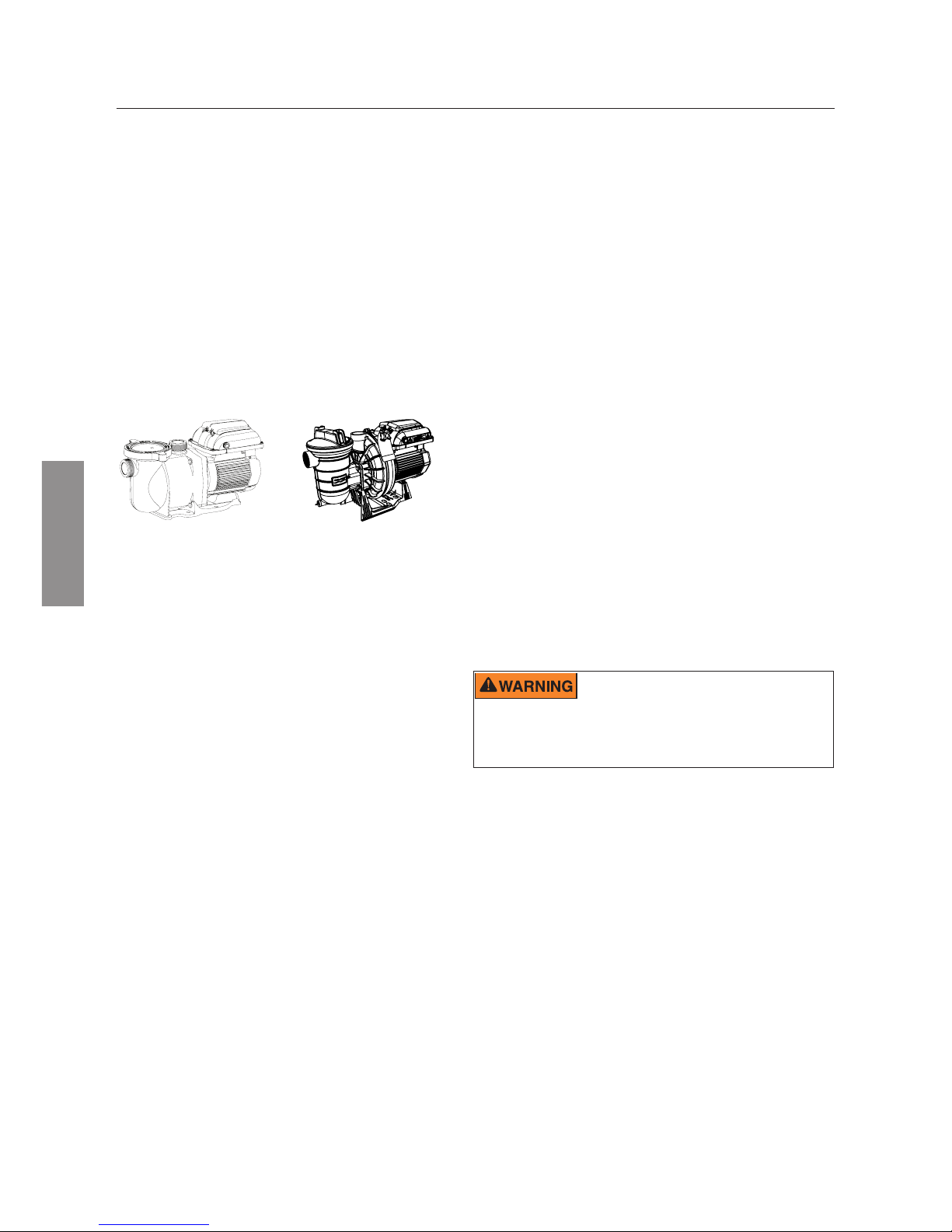
24
FRANCAIS
Description de la pompe
Choix parfait pour tous les types de piscines, la pompe
à vitesse variable VS2 a été spécialement conçue pour
représenter le meilleur choix pour une multitude de
piscines enterrées.
Ses éléments de carrosserie aux parois épaisses, son
moteur TEFC pour usage intensif et son hydraulique
de très haute technologie font de ce concept robuste et
éprouvé la solution parfaite pour tout type de piscine, de
spa, d'animation d'eau ou de fontaine.
Toutes les pompes de Pentair Aquatic Systems intègrent
une technologie hydraulique novatrice qui est peaunée
depuis plus de 40 ans. Compacte, robuste et facile à
entretenir, la pompe VS2 offre des années de service
able.
Pompe SuperMax® VS2
P/N: S5P1R-VS2
Pompe S5P2R™-VS2
P/N: S5P2R-VS2
DESCRIPTION DE LA POMPE
Caractéristiques du contrôleur
• Interface utilisateur simple
• Boîtier IPX6 certié résistant UV et à la pluie
• Heure de bord du programme journalier
• Mode d'amorçage réglable
• Mode Quick Clean programmable
Caractéristiques générales
• Fonctionnement extrêmement silencieux
• Raccords unions (1,5” et 2”) pour un
remplacement aisé
• Couvercle Cam and Ramp™ pour un nettoyage
et une maintenance aisés
• Moteur haute résistance refroidi par ventilateur
entièrement intégré (TEFC) pour une longue
durée de vie.
• La volute et le panier intégrés réduisent le bruit
hydraulique
• Ce couvercle permet une inspection aisée du
panier-tamis
• Auto-amorçante pour un démarrage rapide et
aisé.
• Certié CE/REACH
• Classement IPX6
Description du contrôleur
La pompe à vitesse variable VS2 fait appel à un moteur à vitesse
variable à efcacité supérieure qui offre une grande exibilité
de programmation sur le plan des paramètres de vitesse du
moteur et de durée. La pompe est conçue pour fonctionner
aux vitesses de rotation minimales requises pour maintenir un
environnement sain minimisant, à son tour, la consommation
d'énergie. Les dimensions de la piscine, la présence
d'animations d'eau supplémentaires, les produits chimiques
utilisés pour maintenir des conditions sanitaires et les facteurs
environnementaux locaux inuenceront la programmation
optimale requise pour maximiser les économies d'énergie.
L'interface intégrée de l'électronique commande les réglages
de vitesse et les durées des cycles. La pompe peut fonctionner
selon une plage de vitesses de 300 à 3450 tr/min et selon une
plage de tension allant de 99 à 253 Vrms avec une fréquence
d'entrée de 50 ou 60 Hz.
La personnalisation des programmes
peut impliquer certains tâtonnements an de déterminer les
réglages les plus satisfaisants en fonction des conditions.
Dans la plupart des cas, le réglage de la pompe sur la vitesse
de rotation minimale pendant la durée la plus longue constitue
la meilleure stratégie en vue de minimiser la consommation
d'énergie. Néanmoins, certaines conditions peuvent imposer
de faire fonctionner la
pompe
à des vitesses de rotation plus
élevées pendant un certain temps chaque jour an de maintenir
une filtration correcte permettant d'atteindre une hygiène
satisfaisante.
Remarque : optimisez la pompe en fonction des conditions
individuelles de la piscine. Des conditions spéciques incluant
les dimensions de la piscine, d'autres appareils, des animations
et des facteurs environnementaux peuvent toutes inuer sur les
réglages optimaux.
Cette pompe est conçue pour fonctionner à une
tension nominale de 115/208-230Vrms et dans des
applications de pompe pour piscine UNIQUEMENT. Une connexion à une
tension incorrecte ou toute utilisation dans le cadre d'une autre application
peut endommager l'équipement ou provoquer des dommages corporels.
• Achage et mémorisation des alarmes de
diagnostic
• Correction active du facteur de puissance
• Accepte une puissance d'entrée de 99-253V,
50/60Hz
• Circuit de protection à limitation automatique de
puissance
• Horloge à mémoire 24h pour les coupures de
courant
• Mode verrouillage de clavier
• Accepte les entrées numériques basse tension
d'appareils de commandes externes
Page 25
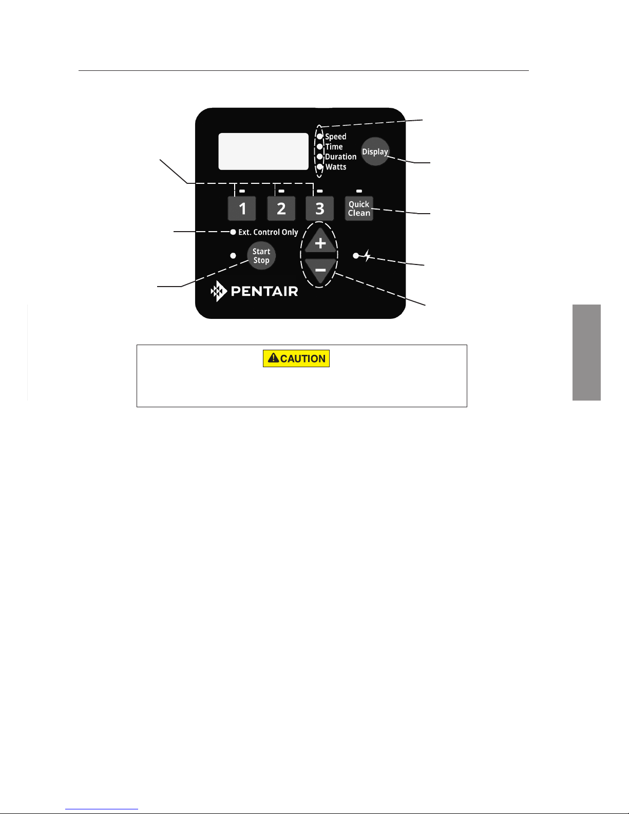
25
FRANCAIS
Si le moteur de la pompe à vitesse variable VS2 est sous tension, il peut être démarré en appuyant
sur n'importe lequel des boutons auxquels il est fait référence dans cette section. Tout non-respect
de cette instruction peut entraîner une blessure corporelle ou endommager l'équipement.
DESCRIPTION DU PANNEAU DE COMMANDE
(1) Boutons de vitesse
(2) Témoin LED Ex-
ternal Control Only
(3) Bouton Start/
Stop
(7) Témoin LED
d'alimentation
(4) Témoins LED du
mode Display
(5) Bouton Display
(6) Bouton Quick
Clean
(8) Flèches « + »
et « - »
Navigation du clavier
1. Boutons de vitesse - Utilisés pour sélectionner la vitesse de marche désirée. Les LED situées
au-dessus des boutons de vitesse s'allument quand cette vitesse est sélectionnée ou est en cours
d'utilisation. Une LED qui clignote indique qu'une commande externe est active sur ce canal de
vitesse.
2. Témoin LED External Control Only - Indique que la pompe fonctionne en mode Commande
externe uniquement. Lorsque la LED est allumée, le programme est désactivé et la seule entrée
provient des commandes externes à basse tension.
3. Bouton Start/Stop - Utilisé pour démarrer/arrêter la pompe. Lorsque la pompe est arrêtée et la LED
éteinte, la pompe ne peut pas tourner, quel que soit le type d'action.
4. Témoins LED du mode Display - Une LED allumée indique la nature des informations achées
à l'écran à un moment donné. Une LED qui clignote indique que le paramètre est actuellement en
cours de modication.
5. Bouton Display - Utilisé pour basculer entre les diérents modes d'achage disponibles. Ce
bouton sert également à régler l'horloge 24h et la résolution de l'écran.
6. Bouton Quick Clean - Utilisé pour lancer une vitesse et une durée programmées du Quick Clean.
Lorsque la LED est allumée, le programme Quick Clean est actif.
7. Témoin LED d'alimentation - La LED allumée signie que la pompe est sous tension.
8. Flèches « + » et « - » - Servent à eectuer les réglages à l'écran des paramètres de la pompe. La
èche « + » permet d'augmenter la valeur d'un paramètre donné alors que la èche « - » la diminue.
Le fait de maintenir appuyé un des deux boutons permet d'augmenter ou diminuer plus rapidement
les modications par incrément.
FRANCAIS
Page 26
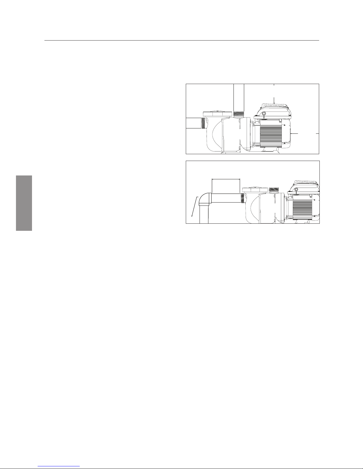
26
INSTALLATION
FRANCAIS
Raccords et vannes
1. Ne pas installer de coudes à 90° directement à
l'entrée de la pompe.
2. Les systèmes d'aspiration immergés doivent avoir
des robinets-vannes intégrés dans les tuyaux
d'aspiration et de décharge pour la maintenance.
Toutefois, le robinet-vanne d'aspiration ne doit pas
être plus près que cinq fois le diamètre du tuyau
d'aspiration, comme décrit ci-dessus.
3. Utilisez un clapet anti-retour dans la conduite de
décharge lorsque vous utilisez cette pompe pour une
application où la hauteur est importante par rapport
à la tuyauterie placée après la pompe.
4. Installez des clapets anti-retour lorsque la tuyauterie
est en parallèle avec une autre pompe. Cela évite les
rotations en sens inverse de la turbine et du moteur.
Alimentation électrique requise
• Installez tout l'équipement conformément à votre
code national électrique et à tous les codes et
règlements locaux en vigueur.
• Il est nécessaire d'intégrer un moyen de
déconnexion au câblage xe conformément aux
règles de câblage.
La pompe à vitesse variable VS2 doit être obligatoirement installée par un plombier qualié. Se référer à
«Avertissements et consignes de sécurité de la pompe» en pages ii-iii au sujet des consignes d'installation
supplémentaires et des informations de sécurité.
5 X LE DIAMÈTRE DU
TUYAU D'ASPIRATION
COUDE
Figure 2.
Emplacement
Remarque : ne pas installer cette pompe dans une
enceinte extérieure ou sous la jupe d'un bain à remous
ou d'un spa sauf mention dans ce sens.
Remarque : assurez-vous que la pompe est
mécaniquement xée au plateau de l'équipement.
Vériez que l'emplacement de la pompe répond
aux exigences suivantes:
1. Installez la pompe le plus près possible de la piscine
ou du spa. Pour réduire les pertes de charge par
frottement et améliorer l'ecacité, utilisez des tuyaux
d'aspiration et de retour courts et directs.
2. Installez la pompe au minimum à 1,50 m de la paroi
intérieure de la piscine et du spa.
3. Installez la pompe au minimum à 1 mètre de la
sortie du radiateur.
4. N'installez pas la pompe à plus de 3 mètres audessus du niveau d'eau.
5. Installez la pompe dans un endroit bien ventilé et
protégé d'une humidité excessive (c.-à-d. tuyaux de
descente d'eaux pluviales, arroseurs, etc.).
6. Installez la pompe avec un écart arrière d'au moins
10cm de sorte que le moteur puisse être démonté
facilement pour la maintenance et la réparation.
Voir Figure 1.
Tuyauterie
1. Pour une tuyauterie de piscine optimisée, il est
recommandé d'utiliser une taille de tuyaux plus
importante.
2. Le diamètre de la tuyauterie du côté aspiration de
la pompe doit être identique ou plus important que
celui de la conduite de retour.
3. La tuyauterie du côté aspiration de la pompe doit
être la plus courte possible.
4. Pour la plupart des installations, Pentair recommande
d'installer une vanne sur les conduites d'aspiration
et de retour an de pouvoir isoler la pompe pendant
les travaux d'entretien courants. Cependant, nous
recommandons également qu'une vanne, un coude
ou un té installés sur la conduite d'aspiration ne soit
pas placé à une distance de l'avant de la pompe
inférieure à cinq (5) fois le diamètre de la conduite
d'aspiration. Voir Figure 2.
Exemple : un tuyau de 2,5 pouces (6,35 cm) requiert une ligne droite de 31,8 cm (12,5 pouces)
avant l'entrée d'aspiration de la pompe. Cela permettra d'amorcer la pompe plus rapidement et elle
fonctionnera plus longtemps.
Remarque : NE PAS installer de coudes à 90° directement à l'entrée ou à la sortie de la pompe.
10 CM
MINIMUM
Figure 1.
15,2 CM MINIMUM
Page 27
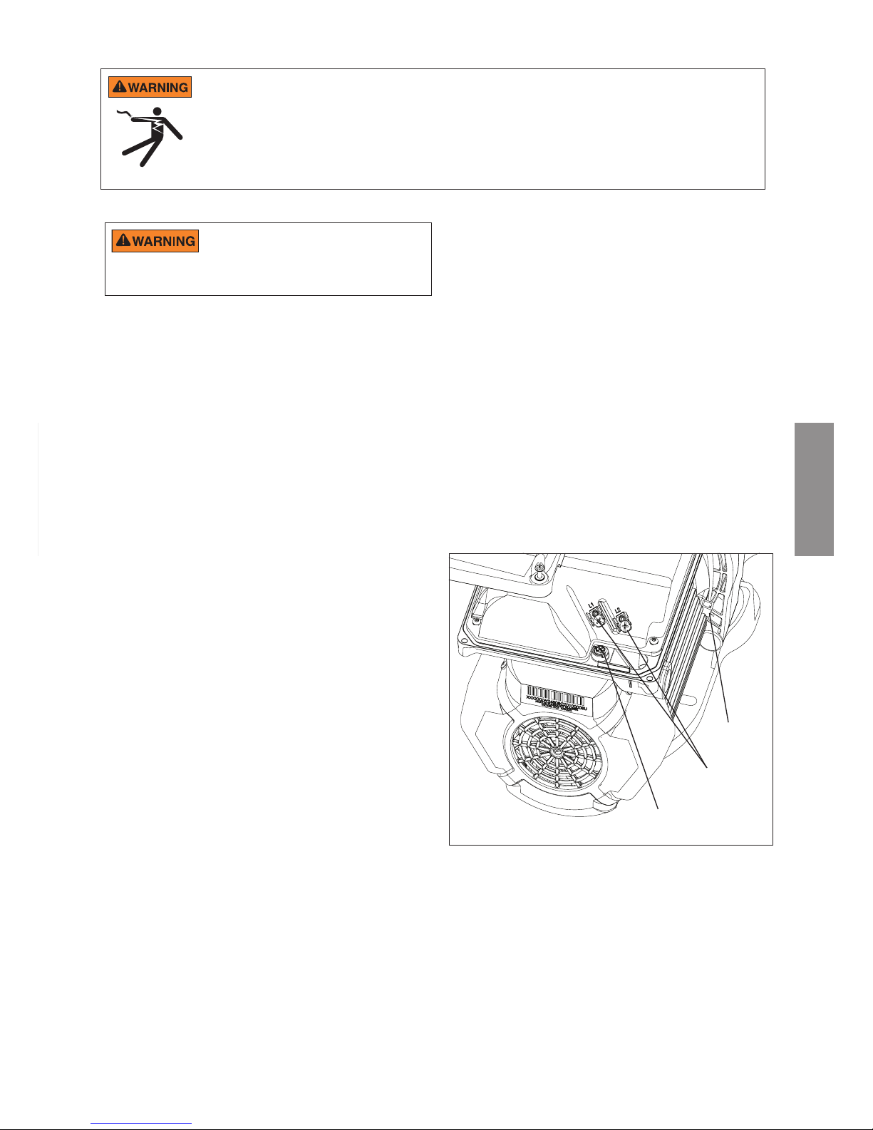
27
FRANCAIS
6. Raccordez le moteur à toutes les pièces métalliques
de la structure de la piscine et à l'ensemble des
équipements électriques, conduites ou tuyauteries
métalliques se trouvant à moins de 1,5 m des parois
intérieures de la piscine, du spa ou du bain à remous
conformément au Code National Électrique en vigueur.
UL requiert l'utilisation d'un conducteur de raccordement
en cuivre massif qui ne soit pas inférieur à 8 AWG.
Voir Figure 3.
Remarque: au Canada, un conducteur de raccordement
en cuivre massif de 6 AWG ou plus est obligatoire.
7. La pompe doit être reliée en permanence à un
disjoncteur, un minuteur 2 pôles ou un relais 2 pôles. Si
le courant CA est fourni par un disjoncteur diérentiel de
fuite à la terre (GFCI), utilisez un disjoncteur spécique
qui n'a pas d'autres charges électriques.
8. Connectez en permanence la pompe à un circuit.
Veillez à ce qu'aucune autre lumière ni aucun appareil
ne soient sur le même circuit.
La pompe doit être câblée conformément aux codes et
normes électriques locales. Reportez-vous toujours au
Code National Électrique. Cette pompe doit être installée
par un électricien agréé.
La pompe accepte une alimentation électrique monophasée
de 99-253 V, 50 ou 60 Hz. Les raccordements du bornier
peuvent accueillir du câble massif ou torsadé de 10 AWG
au maximum. Il existe également des raccords rapides
de type Faston. Cependant, vériez les codes électriques
locaux au sujet de la méthode de raccordement voulue.
Les raccordements doivent être eectués de manière
xe à la borne de mise à la terre (voir Figure 3) dans le
compartiment du câblage d'excitation conformément au
code électrique local. Le boîtier de commande du moteur va
automatiquement réguler la vitesse de la pompe lorsqu'elle
tourne à basse tension an de maintenir le courant en
dessous de 13,2 A. Aucun changement de câblage n'est
nécessaire pour faire fonctionner la pompe avec un courant
nominal de 110V, on utilise les mêmes bornes que pour un
câblage haute tension.
La commande fonctionne sur les systèmes électriques
biphasés Ligne-Ligne-Terre ainsi que sur les systèmes
Ligne-Neutre-Terre. Cette pompe doit être raccordée en
permanence à un disjoncteur selon les spécications du
code électrique local.
1. Vérifiez que tous les interrupteurs et disjoncteurs
électriques sont coupés avant de raccorder le moteur.
Attendez toujours cinq (5) minutes après avoir coupé
l'alimentation électrique de la pompe avant d'ouvrir ou
entretenir le système d'entrainement.
2. Choisissez une taille de câble adaptée à la pompe,
conformément au Code National Électrique et à tous les
codes et règlements locaux en vigueur. En cas de doute,
utilisez un l de plus gros diamètre. Vériez que la tension
du câblage correspond à la plage de fonctionnement.
3. Vérifiez que toutes les connexions électriques sont
propres et étanches.
4. Coupez les ls à la longueur appropriée de sorte qu'ils
ne se chevauchent ou ne se touchent pas quand ils sont
connectés au bornier.
5. Mettez à demeure le moteur à la terre à l'aide de la vis de
terre située sur la face arrière intérieure de l'interface du
contrôleur (voir Figure 3). Utiliser la taille de l correcte et
le type spécié par le Code National Électrique. Vériez
que le l de terre est relié à une terre électrique adéquate.
Description et installation du câblage
Figure 3.
Cosse de
connexion
Branchements électriques CA
Borne de mise à
la terre
Le compartiment du câblage d'excitation comporte un
port leté 1/2” NPT pour le raccordement étanche.
La cosse de connexion doit être utilisée pour relier le
châssis du moteur au plateau de l'équipement.
Le courant doit être coupé lors de l'installation,
de l'entretien ou de la réparation de composants
électriques. Observez tous les avertissements apposés sur l'équipement
existant, la pompe ainsi que dans les présentes instructions d'installation.
RISQUE DE CHOC ÉLECTRIQUE OU D'ÉLECTROCUTION. La pompe à vitesse variable doit être installée par un électricien agréé
ou certié ou un technicien de service qualié conformément au Code National Électrique et à tous les codes et règlements locaux en
vigueur. Une installation incorrecte risque de présenter un danger électrique pouvant entrainer la mort ou des blessures graves aux
utilisateurs, aux installateurs ou à d'autres personnes en raison du choc électrique; elle peut également endommager les biens.
Débranchez toujours le courant de la pompe de piscine au niveau du disjoncteur avant d'intervenir sur la pompe. Tout
manquement à cette obligation est susceptible d'entraîner la mort ou d'occasionner des dommages corporels graves aux
techniciens de service, aux utilisateurs de la piscine ou à d'autres personnes en raison du risque de choc électrique et/ou de
dommage matériel. Lisez toutes les instructions d'entretien avant d'intervenir sur la pompe.
FRANCAIS
Page 28
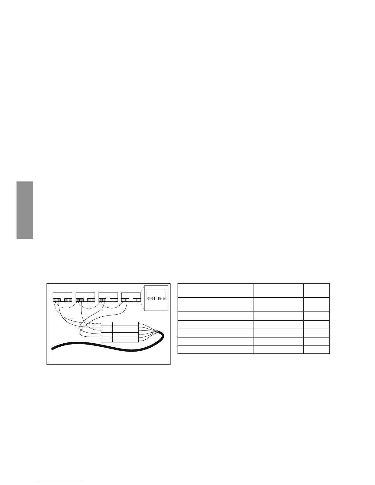
28
FRANCAIS
Contrôle par commande externe et entrées numériques
L'utilisateur peut faire tourner la pompe à vitesse variable VS2 avec des commandes externes d'automatisation ou
Pentair® ControlPro™, ce qui permet de commander à distance les quatre vitesses programmées. La pompe comporte
un connecteur étanche qui peut être utilisé avec le câble de données Pentair (option, Réf. 353129Z) pour exécuter les
vitesses à l'aide de signaux d'entrée numériques. Lorsqu'il y a un signal externe basse tension sur la ligne d'entrée
numérique des vitesses, la pompe tourne à la vitesse programmée pour cette entrée numérique. Le signal +5 V fourni
est l'entrée recommandée utilisée pour la commande externe et les entrées numériques des vitesses.
Connexion aux commandes externes
Utilisation du signal basse tension fourni pour la commande numérique
La pompe VS2 fournit un signal de sortie basse tension qui peut être utilisé pour déclencher ses propres entrées
numériques. Ce signal devra être commuté via le système de commande externe pour engager la vitesse qui y est
connectée comme sur la Figure 4. Ce peut être un relais ou un interrupteur d'automatisation d'un autre équipement.
Cette fonctionnalité peut être utile pour s'assurer que la pompe exécute un certain programme lorsqu'une vitesse
spécique est nécessaire pour eectuer une tâche.
Le l inclus dans le câble de données Pentair (option, Réf. 353129Z) devra être coupé à la bonne longueur pour
l'installation. Ne laissez pas de longueur excessive de câble autour de l'installation. Le l doit avoir un support rigide si
vous n'utilisez pas de conduite. À une extrémité du câble, il y a un raccordement personnalisé moulé et étanche, qui se
branche dans le panneau de connexion du côté du périphérique. L'extrémité opposée comporte 6 ls qui sont dénis
par le Tableau 1 ci-dessous. Si vous utilisez le signal +5 V fourni par le périphérique, les vitesses doivent être câblées
selon les indications de la Figure 4.
Lorsqu'il y a un signal basse tension sur la ligne d'entrée numérique des vitesses, la pompe tourne à la vitesse
programmée pour la vitesse qui est déclenchée. Le signal +5 V fourni via le l (rouge) est l'entrée suggérée pour les
entrées numériques des vitesses. Voir Figure 4.
Remarque : n'importe quel relais peut être associé à n'importe quelle entrée numérique. La Figure 4 illustre une des
options de câblage possibles à disposition de l'installateur, ce qui vous permet d'installer les commandes externes de la
manière la mieux adaptée à vos besoins.
Remarque : ce signal +5 V (l rouge) est émis par le périphérique uniquement, il ne doit jamais être raccordé à
une autre alimentation électrique!
Lorsqu'une entrée numérique de vitesse est déclenchée, la LED placée au-dessus du bouton de vitesse commence
à clignoter et l'achage bascule entre le paramètre d'achage et « EC » pour indiquer qu'une commande externe
est exécutée. La pompe exécute cette vitesse tant que le déclencheur d'entrée numérique est présent. Cette action
neutralise le programme ou toute entrée utilisateur de sélection des vitesses via le clavier. Le bouton Display reste
fonctionnel, ainsi que le bouton Start/Stop. Une fois que le déclencheur d'entrée numérique est enlevé de tous les ls
d'entrée numérique de vitesse, la pompe reprend le programme planié.
RELAY 1 RELAY 2 RELAY 3 RELAY 4
RELAY
LINE 1
LOAD 1
LOAD 2
LINE 2
POWER RELAY (DPST)
RED
+5V OUTPUT FOR D.I. TRIGGERS
GREEN
SPEED 1 DIGITAL INPUT
YELLOW
SPEED 2 DIGITAL INPUT
ORANGE
SPEED 3 DIGITAL INPUT
BROWN
SPEED 4 DIGITAL INPUT
BLACK
GROUND
Figure 4 :
Schéma de câblage du kit de commande externe
Dénition Plage du signal
Couleur
du l
Sortie +5 V pour entrées
numériques
0 - 20 mA Rouge
Entrée numérique vitesse 1 0, 5 - 30 V CA/CC Vert
Entrée numérique vitesse 2 0, 5 - 30 V CA/CC Jaune
Entrée numérique vitesse 3 0, 5 - 30 V CA/CC Orange
Entrée numérique Quick Clean 0, 5 - 30 V CA/CC Marron
Terre commune 0 V Noir
Tableau 1 :
Schéma de câblage d'entrée du système de commande
d'automatisation
Utilisation d'un signal basse tension fourni en externe pour la commande externe
Lors de l'utilisation d'un signal basse tension fourni en externe comme déclencheur d'entrée numérique, le l doit
être connecté selon les illustrations de la Figure 5. L'entrée basse tension doit être dans la plage 5-30 V CA ou
CC. Dans ce cas, l'alimentation rouge +5V provenant de la commande du moteur n'est pas utilisée.
Remarque : ce signal +5 V (l rouge) est émis par le périphérique uniquement, il ne doit jamais être raccordé à
une autre alimentation électrique!
Le signal externe basse tension peut être régulé par des commutateurs ou des relais permettant d'activer l'entrée
numérique voulue. Si plusieurs entrées numériques sont actives à un moment donné, elles sont résolues par
ordre de priorité.
Page 29
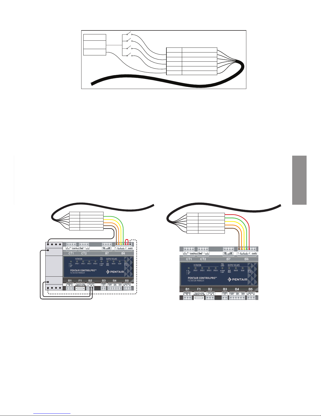
29
FRANCAIS
RED
+5V OUTPUT FOR D.I. TRIGGER
GREEN
SPEED 1 DIGITAL INPUT
YELLOW
SPEED 2 DIGITAL INPUT
ORANGE
SPEED 3 DIGITAL INPUT
BROWN
SPEED 4 DIGITAL INPUT
BLACK
GROUND
EXTERNAL LOW
VOLTAGE SUPPLY
5-30 V AC/DC
GROUND
Remarque : si la pompe a été arrêtée via le bouton Start/Stop, elle ne fonctionne pas tant qu'elle n'a pas été remise en
marche en appuyant sur le bouton Start/Stop. Si la LED Start/Stop est allumée, cela indique que la pompe est sous
tension et fonctionnera via les entrées numériques.
Remarque : s'il y a plusieurs déclencheurs basse tension, ils sont résolus selon cet ordre de priorité : Quick Clean,
vitesse 3, vitesse 2, puis vitesse 1.
Connexion à Pentair® ControlPro™
Si vous recherchez une installation commandée en externe, Pentair® ControlPro™ peut proposer une solution simple
pour la conguration globale de la piscine. La sélection de vitesse est eectuée par ControlPro™, via l'interface. Pour
en savoir plus, visitez le site www.pentairpooleurope.com. La connexion doit être réalisée selon les illustrations de la
Figure 6. La bonne entrée basse tension provient de ControlPro™, la terre doit donc être raccordée au contacteur.
Lorsque vous raccordez la pompe VS2 à ControlPro™, consultez toujours le manuel ControlPro sur le site www.
pentairpooleurope.com.
Mode Commande externe uniquement
Le mode Commande externe uniquement permet à la pompe de fonctionner uniquement à partir de commandes/entrées
externes. Lorsque ce mode est actif, le programme déni pour la pompe est désactivé et les demandes de vitesse eectuées
sur le clavier par l'utilisateur ne sont pas acceptées. Si la pompe est arrêtée, un utilisateur peut toujours programmer les
vitesses pour les quatre boutons de vitesse.
FRANCAIS
Figure 5: Schéma de câblage d'alimentation électrique basse tension
1
A1
A2
3 5 7
2 4 6 8
RED
+5V OUTPUT FOR D.I. TRIGGER
GREEN
SPEED 1 DIGITAL INPUT
YELLOW
SPEED 2 DIGITAL INPUT
ORANGE
SPEED 3 DIGITAL INPUT
BROWN
SPEED 4 DIGITAL INPUT
BLACK
GROUND
RED
+5V OUTPUT FOR D.I. TRIGGER
GREEN
SPEED 1 DIGITAL INPUT
YELLOW
SPEED 2 DIGITAL INPUT
ORANGE
SPEED 3 DIGITAL INPUT
BROWN
SPEED 4 DIGITAL INPUT
BLACK
GROUND
Figure 6: Schéma de câblage ControlPro Figure 6: Schéma de câblage ControlPro+
Page 30
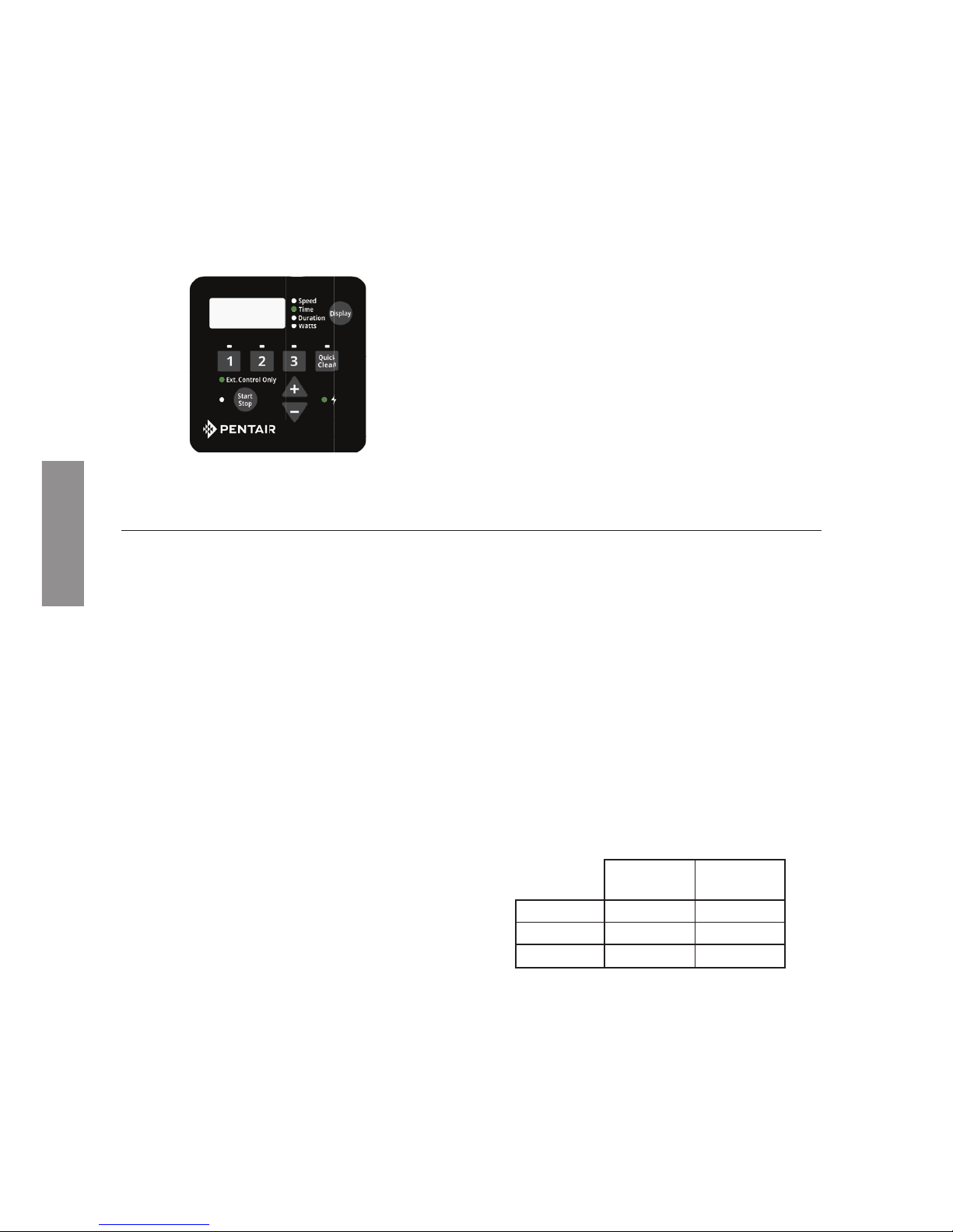
30
FRANCAIS
9:00Pm
Figure 7: Activation du mode
Commande externe uniquement
Pour activer le mode Commande externe
uniquement:
1. Arrêtez la pompe en appuyant sur le bouton Start/
Stop.
2. Activez le mode Commande externe uniquement
en appuyant sur le bouton Start/Stop et en le
maintenant enfoncé pendant 3 secondes.
3. Si la commande fonctionne, la LED située près de
Ext. Control Only s'allume. Voir Figure 7.
4. Il faut appuyer à nouveau sur le bouton Start/Stop
pour que la pompe puisse fonctionner.
Pour désactiver le mode Commande externe
uniquement:
1. Arrêtez la pompe en appuyant sur le bouton Start/
Stop.
2. Désactivez le mode Commande externe
uniquement en appuyant sur le bouton Start/Stop
et en le maintenant enfoncé pendant 3 secondes.
3. Si la commande fonctionne, la LED située près de
Ext. Control Only s'éteint. Voir Figure 7.
4. Il faut appuyer à nouveau sur le bouton Start/Stop
pour que la pompe puisse fonctionner.
FONCTIONNEMENT DE LA POMPE
Réglage de l’horloge
Lorsque la pompe est branchée pour la première fois,
l'horloge clignote pour indiquer qu'elle n'est pas réglée.
Tous les programmes quotidiens définis par l'utilisateur
sont basés sur cette horloge, il faut donc la régler d'abord.
Pour régler l'horloge:
1. Appuyez sur le bouton Display et maintenez-le
enfoncé pendant 3 secondes.
2. Utilisez les èches « + » et « - » pour choisir le format
d'achage 12 ou 24 heures.
3. Appuyez sur Display pour continuer dans le menu
de réglage de l’horloge
4. Utilisez les èches « + » et « -» pour ajuster l'heure
du jour. En format d'affichage 12 heures, AM/PM
s'ache dans le coin inférieur droit.
5. Appuyez sur Display pour continuer.
6. Utilisez les flèches « + » et « - » pour régler la
luminosité du rétro-éclairage de l'écran.
7. Appuyez sur Display pour sortir du menu de réglage
de l’horloge. L'horloge est maintenant réglée.
En cas de coupure de courant, le périphérique conserve
le réglage de l'horloge en mémoire pendant 24 heures.
Si le courant est coupé plus de 24 heures, l'horloge doit
être réglée à nouveau. Si le périphérique a perdu l'heure
réglée par l'utilisateur, l'horloge clignote en permanence
jusqu'au réglage de l'heure.
Une fois que l'heure est réglée, l'horloge cesse de
clignoter.
Remarque: quand la pompe est remise sous tension
après une coupure prolongée (plus de 24 heures),
l'horloge va automatiquement se régler d'elle-même sur
l'heure de début de la vitesse 1, clignoter et avancer. La
pompe va également exécuter le programme associé
à partir de cette heure de début.
Utilisation du programme par défaut
Le programme par défaut est conçu pour fournir
suffisamment de débit journalier pour entretenir une
piscine classique. Voir le Tableau 2 au sujet du
programme par défaut.
Durée
(Heures)
Vitesse
(tr/min)
VITESSE 1 2 3000
VITESSE 2 10 1400
VITESSE 3 2 2200
Tableau 2 : Programme par défaut.
Le programme VITESSE 1 est réglé pour commencer
à 8h00 et fonctionner à 3000 tr/min pendant une
durée de 2 heures. Lorsque le programme VITESSE
1 est terminé, la pompe commence immédiatement
à exécuter le programme par défaut VITESSE 2.
Le programme VITESSE 2 est réglé par défaut en
usine sur 1400tr/min et dure 10 heures. Lorsque le
Page 31

31
FRANCAIS
Remarque: le paramètre de durée est réglé par
incréments de 15 minutes.
8. En appuyant sur le bouton « 1 », vous continuez à
naviguer dans ces paramètres, mais les modications
sont immédiatement enregistrées dès qu'elles sont
réglées.
9. Appuyez sur le bouton « 2». La LED placée audessus de VITESSE 2 commence à clignoter et la
LED du paramètre correspondant clignote pendant
la modication.
10. Utilisez les èches « +» et «- » pour régler la vitesse
en tr/min de VITESSE 2.
11. Appuyez à nouveau sur le bouton « 2 » et l'achage
passe à la durée de VITESSE 2.
Remarque: Les programmes VITESSE 2 et 3 n'ont
pas d'heure de début, parce qu'ils commencent
immédiatement dès que le programme VITESSE
précédent se termine.
12. Utilisez les èches « +» et «-» pour régler la durée
de VITESSE 2 en heures et minutes.
13. Répétez les étapes de 9 à 12 pour programmer
VITESSE 3 et QUICK CLEAN.
Remarque: souvenez-vous que la durée possible
pour VITESSE 3 est limitée au temps restant sur une
journée de 24 heures. Pour toute heure d'une journée
de 24 heures non programmée pour les programmes
VITESSE 1-3, la pompe reste en état stationnaire.
[ VITESSE 1 + VITESSE 2 + VITESSE 3 < 24 heures ]
14. Appuyez sur le bouton Start/Stop et vérifiez que
la LED est allumée. La pompe est désormais sous
tension et va exécuter le programme personnalisé
défini par l'utilisateur.
Programmes personnalisés
Pour personnaliser le programme de fonctionnement
de votre pompe à vitesse variable VS2, elle doit être
arrêtée. Vérifiez que la LED du bouton Start/Stop
n'est pas allumée.
Programmation d'un programme personnalisé:
Remarque: Pendant la programmation, la LED située
près du paramètre que vous réglez («Speed », «Time»
et «Duration») clignote.
1. Si elle fonctionne, arrêtez la pompe en appuyant
sur le bouton Start/Stop.
2. Appuyez sur le bouton « 1». La LED placée audessus de la VITESSE sélectionnée commence à
clignoter et la LED du paramètre «Speed » clignote
pendant la modication. Voir Figure 8.
3. Utilisez les flèches « +» et « -» pour régler la
vitesse en tr/min de VITESSE 1.
Remarque: la vitesse est augmentée ou diminuée
par incréments de 10tr/min.
4. Appuyez à nouveau sur le bouton «1» et l'achage
passe à l'heure de début de VITESSE 1. La LED
du paramètre «Time » commence à clignoter.
Voir Figure 9.
5. Utilisez les èches « + » et «-» pour régler l'heure
de début quotidienne de VITESSE 1.
6. Appuyez à nouveau sur le bouton «1» et l'achage
passe à la durée de VITESSE 1. La LED du
paramètre «Duration» commence à clignoter.
Voir Figure 10.
7. Utilisez les èches « +» et «-» pour régler la durée
de VITESSE 1 en heures et minutes.
3000
Figure 8 : Réglage de la vitesse
8:00AM
Figure 9 : Réglage de l'heure de début
2:00
Figure 10 : Réglage de la durée
programme VITESSE 2 a terminé son cycle, la pompe
exécute VITESSE 3 à 2200tr/min pendant une durée
de deux heures.
Après 14 heures de fonctionnement, à la n du cycle
de VITESSE 3, la pompe se met en pause pendant les
10 heures suivantes. La pompe redémarre à 8h 00
le matin suivant et exécute à nouveau le programme
par défaut. La pompe fonctionne de cette manière tant
qu'un programme personnalisé n'est pas défini dans
le périphérique par l'utilisateur.
Remarque: il faut appuyer sur le bouton Start/Stop et
que la LED soit allumée pour que la pompe fonctionne.
FRANCAIS
Page 32

32
FRANCAIS
Remarque: si la pompe a été arrêtée via le bouton
Start/Stop, elle ne fonctionne pas tant qu'elle n'a pas
été remise sous tension en appuyant sur le bouton
Start/Stop. Si la LED Start/Stop est allumée, la pompe
est sous tension et exécutera le programme déni.
Utilisation de la pompe pendant qu'elle
fonctionne
Des pressions sur le bouton Display permettent de
parcourir les diérents paramètres en cours.
• Speed — Vitesse d'exécution actuelle
• Time — Heure de la journée actuelle
• Duration — Temps restant à la vitesse
actuelle
• Watts — Nombre de watts actuellement
consommés
Si le moteur de la pompe est sous tension, le moteur peut être démarré
en appuyant sur n'importe lequel des boutons auxquels il est fait référence
dans cette section. Tout non-respect de cette instruction peut entraîner une
blessure corporelle ou endommager l'équipement.
Priorités des vitesses (commande non
externe)
Pour les paramètres de durée, les programmes VITESSE
ont la priorité suivante: VITESSE 1 -> VITESSE 2 ->
VITESSE 3 VITESSE 1 est la priorité la plus élevée alors
que VITESSE 3 est la plus basse.
Le périphérique ne permet pas à un utilisateur de dénir
un programme qui dure plus de 24 heures. Lorsque la
24e heure de durée est programmée, il prélève du temps
sur les vitesses à basse priorité afin de les ajouter au
programme VITESSE en cours de réglage.
Exemple:
Programme de départ (avant réglage)
Durée de VITESSE 1 = 20 heures
Durée de VITESSE 2 = 2 heures
Durée de VITESSE 3 = 2 heures
Si l'utilisateur reprogramme VITESSE 1 pour une
exécution pendant 23 heures, VITESSE 2 (vitesse à
priorité inférieure) sera automatiquement réglé sur
une durée d'1 heure et VITESSE 3 (vitesse à priorité
la plus faible) sera réglé sur une durée de 0 heure.
Programme nal (après réglage)
Durée de VITESSE 1 = 23 heures
Durée de VITESSE 2 = 1 heure
Durée de VITESSE 3 = 0 heure
Remarque: Si un utilisateur veut que la pompe ne
fonctionne pas pendant une période de la journée, un
des programmes VITESSE peut être réglé sur 0tr/min.
Cela aura pour eet de maintenir la pompe en pause
pendant la durée de ce programme VITESSE.
Un appui sur n'importe quel bouton de vitesse (1, 2, 3,
Quick Clean) pendant que la pompe fonctionne sert de
forçage temporaire. La vitesse et la durée programmées
pour ce bouton sont exécutées. Une fois terminé, le
programme défini reprend par défaut au point approprié.
Remarque: si vous réglez les vitesses du programme
pendant que la pompe fonctionne, la vitesse réglée est
appliquée pendant le reste de la durée en cours, mais
les réglages ne sont pas enregistrés. Exception: les
réglages de vitesse et de durée de QUICK CLEAN
sont toujours enregistrés immédiatement.
Quick Clean
Si Quick Clean est en cours d'exécution, une pression
sur les flèches « + » ou « - » change la vitesse en
conséquence. En appuyant à nouveau sur le bouton
Quick Clean dans les 10 secondes suivant la pression
sur les flèches « + » ou « - », vous pourrez régler la
durée de Quick Clean avec les flèches « + » et « - ».
Ces modifications sont enregistrées immédiatement et
deviennent les nouvelles valeurs par défaut de Quick
Clean. Une nouvelle pression sur le bouton Quick
Clean permet de parcourir les deux paramètres de Quick
Clean. La pompe quitte le mode modification si vous
n'appuyez sur aucun autre bouton dans les 10 secondes.
Si Quick Clean est en cours d'exécution et que vous
désirez l'arrêter avant que la durée soit terminée,
vous pouvez appuyer sur le bouton Quick Clean et
le maintenir enfoncé pendant 3 secondes : la pompe
reviendra au point approprié du programme défini.
Dans de rares conditions, certaines vitesses du moteur
peuvent causer des bruits de résonnance dans la
pompe, ceci peut être résolu simplement en modiant
légèrement la vitesse.
Page 33

33
FRANCAIS
Cette pompe est expédiée avec le mode d'amorçage ACTIVÉ. À moins que les paramètres d'amorçage ne soient
changés dans le menu, sachez que la pompe va accélérer jusqu'à la vitesse d'amorçage quand elle sera mise
sous tension pour la première fois et que vous appuierez sur le bouton Start/Stop.
Avant de mettre la pompe EN MARCHE, vériez que les conditions suivantes sont remplies:
1. Ouvrez le purgeur d'air du ltre.
2. Ouvrez les vannes.
3. Le retour de la piscine est entièrement ouvert et n'est pas obstrué.
4. Il y a de l'eau dans le panier de la pompe.
5. Tenez-vous à distance du ltre ou des autres réservoirs sous pression.
NE FAITES PAS fonctionner la pompe à sec. Si la pompe fonctionne à sec, la garniture mécanique risque d'être
endommagée et la pompe commencera à fuir. Si cela se produit, le joint endommagé doit être remplacé. Maintenez
TOUJOURS un niveau d’eau approprié dans votre piscine (skimmer semi-ouvert) Si le niveau d’eau chute sous l'ouverture du skimmer,
la pompe aspirera de l'air, perdra son amorce, fonctionnera à sec et endommagera le joint. Un fonctionnement continu avec un niveau
d'eau inadéquat pourrait provoquer une perte de pression susceptible d'entraîner des dégâts au carter de pompe, à la turbine et au joint
et risquerait de provoquer des dommages matériels et corporels.
L'amorçage va automatiquement s'exécuter lorsque la
pompe à vitesse variable VS2 est démarrée en étant à
l'arrêt, sauf en cas d'exécution du mode Quick Clean.
L'amorçage s'eectue par défaut à 2850 tr/min et dure 5
minutes. L'écran du périphérique ache alternativement
les éléments suivants: « PrI - Priming Speed, PrI
-- Remaining Time».
Une fois que l'amorçage a commencé, la vitesse peut
être réglée entre 3450 et 1700 tr/min avec les flèches
«+ » et « -». S'il est réglé à moins de 1700 tr/min, le
mode d'amorçage est désactivé et la pompe commence
immédiatement à exécuter la vitesse programmée.
Lorsque l'amorçage est désactivé et la pompe est
démarrée en étant à l'arrêt, l'écran affiche «PrI OFF » pendant 10 secondes tout en exécutant la
vitesse programmée (Voir Figure 11). Cela donne à
l'utilisateur le temps d'activer le mode d'amorçage en
appuyant sur la flèche «+ ». Si l'utilisateur choisit de
réactiver le mode d'amorçage, la pompe passe alors de
la vitesse programmée à 1700 tr/min. L'utilisateur peut
augmenter la vitesse d'amorçage à partir de 1700 tr/min
en appuyant sur la èche «+». Le minuteur du compte
à rebours de 5 minutes de l'amorçage démarre lorsque
l'amorçage est lancé pour la première fois.
L'installateur doit dénir une vitesse d'amorçage susante
pour amorcer la pompe dans une nouvelle installation,
mais pas trop rapide pour éviter un gaspillage important
d'énergie pendant le créneau d'amorçage de 5 minutes.
La durée pendant laquelle la pompe doit s'amorcer peut
changer selon les conditions environnementales locales,
par exemple température de l'eau, pression atmosphérique
et niveau d'eau de la piscine. L'ensemble de ces facteurs
doit être pris en compte lors du réglage de la vitesse
d'amorçage, mais dans la plupart des cas, la pompe
n'a pas besoin de tourner à 2850 tr/min pour s'amorcer
correctement d'elle-même.
Veuillez tester et vérifier les vitesses d'amorçage
plusieurs fois en laissant l'eau s'évacuer du système
entre chaque test.
Remarque: le panier du pré-ltre de la pompe doit toujours
rester rempli jusqu'au bas de l'orifice d'admission afin
d'empêcher l'air d'entrer dans le système.
Figure 11 : Désactivation de l'amorçage
PrI
OFF
Amorçage
FRANCAIS
Page 34

34
FRANCAIS
Quick Clean
La pompe à vitesse variable est équipée d'une fonction Quick
Clean qui peut être activée pour faire tourner temporairement la
pompe à des vitesses supérieures ou inférieures allant de 300 à
3450 tr/min. Une fois la durée de Quick Clean écoulée, la pompe
revient automatiquement au programme paramétré.
Programmation de Quick Clean:
1. Si elle fonctionne, arrêtez la pompe en appuyant
sur le bouton Start/Stop.
2. Appuyez sur le bouton Quick Clean . La LED
placée au-dessus de Quick Clean et la LED
du paramètre «Speed» clignotent pendant la
modication. Voir Figure 12.
3. Utilisez les èches «+» et «-» pour régler la
vitesse en tr/min de Quick Clean.
4. Appuyez à nouveau sur le bouton «Quick
Clean» et l'achage passe à la durée de Quick
Clean. La LED du paramètre «Duration»
clignote pendant la modication. Voir Figure 13.
Remarque: la fonction Quick Clean ne
comporte pas d'heure de début.
5. Utilisez les èches «+» et «-» pour régler la
durée en heures et minutes de Quick Clean.
6. Appuyez sur le bouton Start/Stop et vériez que
la LED est allumée. La pompe est maintenant
sous tension et va appliquer la vitesse et la
durée dénies pour Quick Clean.
Remarque : à la n de la durée du Quick Clean, la pompe reprend
le programme de 24 heures au point où il devait normalement se
dérouler à cette heure-là. La durée du Quick Clean n'affecte pas
les heures de début ou de n du programme de 24 heures. Par
exemple, si Quick Clean s'exécute durant une période chevauchant
la n de VITESSE 1 et le début de VITESSE 2, l'heure de début de
VITESSE 3 n'est pas affectée.
Remarque : pour annuler le mode Quick Clean, appuyez sur la
touche Quick Clean et maintenez-la enfoncée pendant plus de
trois (3) secondes.
Remarque : durant le mode Quick Clean, la pompe ne démarre
pas avec la séquence d'amorçage.
Remarque : il est conseillé de ne pas régler la durée de Quick
Clean sur 0 HRS. Si vous réglez la durée de Quick Clean sur 0
HRS, vous ne pouvez pas modier le paramètre de durée quand le
moteur fonctionne. Si la durée est réglée sur 0 HRS, le moteur doit
être arrêté pour pouvoir modier les paramètres de Quick Clean.
Verrouillage du clavier
L'interface utilisateur de la pompe à vitesse variable VS2 possède
une fonction de verrouillage du clavier an d'empêcher toute
modication indésirable des paramètres. Lorsqu'il est verrouillé,
le clavier accepte uniquement l'appui sur le bouton Display pour
parcourir les informations afchées à l'écran et l'appui sur le bouton
Start/Stop pour arrêter le moteur.
Le clavier peut être verrouillé en appuyant simultanément sur
le bouton « 1 » et le bouton Quick Clean et en les maintenant
enfoncés pendant au moins trois secondes. « Loc On » s'afche si
la commande est acceptée.
Le clavier peut être déverrouillé en appuyant simultanément sur
le bouton « 1 » et le bouton Quick Clean et en les maintenant
enfoncés pendant au moins trois secondes. « Loc O » s'afche
si la commande est acceptée.
Remarque : pendant le fonctionnement en mode verrouillage du
clavier, le moteur peut toujours être arrêté en appuyant sur le bouton
Start/Stop. Cependant, le moteur ne peut pas être redémarré tant
que l'utilisateur n'a pas déverrouillé le clavier.
Le verrouillage du clavier n’empêche pas l’arrêt du moteur en appuyant
sur le bouton Start/Stop. Ensuite, il ne peut pas être redémarré tant
que le clavier n'a pas été déverrouillé. Si le moteur fonctionne en mode
verrouillage du clavier et est actionné par des commandes externes, il
peut fonctionner uniquement lorsque la LED Start/Stop est allumée.
3450
Figure 12 : Réglage de la vitesse de Quick Clean
2:00
Figure 13 : Réglage de la durée de Quick Clean
Page 35

35
FRANCAIS
Réinitialisation aux paramètres
d'usine
Si nécessaire, le périphérique peut être réinitialisé
aux paramètres d'usine. La réinitialisation eace
l'ensemble des paramètres utilisateur enregistrés
ayant été programmés, sauf l'heure du jour. Avant
d'eectuer une réinitialisation, assurez-vous qu'elle
est nécessaire, parce que ses eets sont immédiats.
Pour eectuer une réinitialisation:
1. Si nécessaire, arrêtez la pompe en appuyant sur
le bouton Start/Stop.
2. Relevez l'ensemble des paramètres du
programme personnalisé à l'aide du Tableau
3. Vous trouverez ces paramètres en appuyant
sur les boutons «1», «2», «3» et «Quick
Clean», puis en faisant déler tous les écrans.
Notez également la vitesse d'amorçage.
3. Appuyez sur les boutons «1», «2», «3» et
«Quick Clean», puis maintenez-les enfoncés
pendant 3 secondes.
4. L'écran ache «FACt rSt» si la réinitialisation
est réussie. Voir Figure 14.
5. Redénissez le programme et la vitesse
d'amorçage après la réinitialisation. La pompe
doit être remise sous tension avec le bouton
Start/Stop pour pouvoir fonctionner à nouveau.
La pompe va exécuter le programme déni à
partir de l'heure de début initiale.
Remarque: la réinitialisation ne peut pas être
eectuée si le clavier est verrouillé.
Vitesse
(tr/min)
Durée
(Heures)
Heure de début
(Horloge)
VITESSE 1
VITESSE 2
VITESSE 3
QUICK
CLEAN
Vitesse
d'amorçage
Tableau 3 : Programmes dénis par l'utilisateur
Figure 14 : Réinitialisation du périphérique
FACt
rSt
FRANCAIS
Page 36

36
FRANCAIS
Nettoyage du panier de pré-ltre de la pompe
1. Appuyez sur le bouton Start/Stop pour arrêter la
pompe et éteignez la pompe avec le disjoncteur.
2. Purgez la pression dans le système en refroidissant
l'eau.
3. Tapotez doucement le collier dans un sens antihoraire
pour déposer le collier et le couvercle.
4. Éliminez les débris et rincez le panier. Remplacez
le panier s'il est ssuré.
5. Replacez le panier dans le boitier. Veillez à aligner
l'encoche dans le fond du panier sur la nervure dans
le fond de la volute.
6. Remplissez le panier de pré-ltre de la pompe et la
volute avec de l'eau jusqu'à l'orice d'entrée.
7. Nettoyez le couvercle, le joint torique et la surface
d'étanchéité du panier de la pompe. Remarque : il
est important de garder le joint torique du couvercle
propre et bien lubrié.
8. Remettez en place le couvercle en mettant le
couvercle sur le panier. Assurez-vous que le joint
torique du couvercle est bien en place. Placez le
collier et le couvercle sur la pompe, puis tournez
dans le sens horaire jusqu'à ce que les poignées
soient horizontales.
9. Mettez sous tension au disjoncteur du boîtier. Le
cas échéant, réinitialisez l'horloge de la piscine à
l'heure correcte.
10. Ouvrez la purge d'air manuelle au-dessus du ltre.
11. Tenez-vous éloigné du ltre. Démarrez la pompe.
12. Purgez l'air du ltre jusqu'à ce qu'un jet d'eau constant
sorte. Fermez la vanne de décharge d'air manuelle.
MAINTENANCE
Panier de pré-ltre de la pompe
Le panier de pré-filtre de la pompe (ou «passoire »,
«récipient à cheveux et peluches») se trouve devant la
volute. La chambre contient le panier qui doit rester propre
et exempt de feuilles et de débris à tout moment. Pour vérier
s'il y a des feuilles et des débris, observez le panier par le
«couvercle transparent».
Quel que soit l'intervalle entre les nettoyages de ltre, il est
très important d'inspecter visuellement le panier au moins
une fois par semaine.
N'OUVREZ PAS le panier de pré-ltre si la pompe à vitesse variable VS2 ne s'amorce pas ou si elle a fonctionné sans eau dans
le panier de pré-ltre. Les pompes actionnées dans ces circonstances peuvent connaître une accumulation de pression de vapeur
et contenir de l'eau chaude. L'ouver ture de la pompe peut provoquer de graves blessures. An d'éviter le risque de blessures,
assurez-vous que les vannes d'aspiration et de décharge sont ouvertes et que la température du panier de pré-ltre est froide au
toucher, puis ouvrez la pompe avec une extrême précaution.
Pour éviter des dégâts à la pompe et au ltre et pour un fonctionnement correct du système, nettoyez régulièrement le panier de
pré-ltre et les paniers du skimmer.
CE SYSTÈME FONCTIONNE SOUS HAUTE
PRESSION. Lorsqu'une partie du système de
circulation (p. ex., bague de retenue, pompe, ltre,
vannes, etc.) est en cours d'entretien, l'air peut
pénétrer dans le système, qui se dépressurise. De
l'air sous pression peut entraîner une séparation
du couvercle, ce qui peut engendrer des blessures
graves, la mort ou des dommages matériels. Pour
éviter ce risque potentiel, suivez les instructions
ci-dessus.
Ensemble de panier de pré-ltre
Hivernage
Il vous incombe de déterminer le moment où des
conditions de gel peuvent survenir. Si des conditions de
gel sont attendues, prenez les mesures suivantes pour
réduire les risques de dégâts dus au gel. Les dégâts
dus au gel ne sont pas couverts par la garantie.
Pour éviter des dégâts par le gel, suivez les procédures
reprises ci-dessous:
1. Appuyez sur le bouton Start/Stop pour arrêter la
pompe et coupez le courant de la pompe avec le
disjoncteur.
2. Purgez l'eau du boitier de la pompe en déposant
les deux bouchons de purge s'ouvrant avec le
pouce du boitier. Rangez les bouchons dans le
panier de pompe.
3. Recouvrez le moteur pour le protéger de la pluie,
de la neige ou du gel.
Note : ne couvrez pas le moteur de plastique ou d'un
autre matériau étanche à l'air pendant l'hivérisation. Le
moteur peut être couvert pendant un orage, pour l'hiver,
etc., mais jamais quand il fonctionne ou quand il est prévu
de le faire fonctionner.
Remarque : dans les zones tempérées, en cas de gel
temporaire, faites tourner la ltration toute la nuit pour
éviter le gel.
GASKET
Page 37

37
Entretien du moteur électrique
Protection contre la chaleur
1. Mettez le moteur à l'abri du soleil.
2. Tout local clos doit être bien ventilé pour éviter une
surchaue.
3. Prévoyez une ventilation transversale susante.
Protection contre la saleté
1. Protégez de toute matière étrangère.
2. Ne stockez (ou déversez) pas de produits chimiques
sur le moteur ou près de celui-ci.
3. Évitez de balayer ou de remuer la poussière près du
moteur quand il fonctionne.
4. Si un moteur a été endommagé par la saleté, la
garantie sera annulée.
5. Nettoyez le couvercle et le collier, le joint torique et la
surface d'étanchéité du panier de la pompe.
Protection contre l'humidité
1. Protégez des projections d'eau.
2. Protégez des intempéries, telles que des inondations.
3. Si l'intérieur d'un moteur est mouillé, laissez-le sécher
avant de l'utiliser. Ne pas laisser la pompe fonctionner
si elle a été inondée.
4. Si un moteur a été endommagé par l'eau, la garantie
peut être annulée.
ENTRETIEN COURANT
NE FAITES PAS fonctionner la pompe à sec. Si la pompe fonctionne à sec, le joint mécanique risque de s'abîmer et la pompe
commencera à couler. Si cela se produit, le joint endommagé doit être remplacé. Gardez TOUJOURS le niveau d'eau adéquat. Si le
niveau d’eau chute sous l'orice d'aspiration, la pompe aspirera de l'air par l'orice d'aspiration, perdra son amorce, fonctionnera à sec et endommagera
le joint. Un fonctionnement continu avec un niveau d'eau inadéquat pourrait provoquer une perte de pression susceptible d'entraîner des dégâts au carter
de pompe, à la turbine et au joint et risquerait de provoquer des dommages matériels et corporels.
Débranchez toujours le courant de la pompe à vitesse variable VS2 au niveau du disjoncteur et déconnectez le câble de
communication avant d'intervenir sur la pompe. Tout manquement à cette obligation est susceptible d'entraîner la mort ou
d'occasionner des dommages corporels graves aux techniciens de service, aux utilisateurs de la piscine ou à d'autres personnes en raison du risque
d'électrocution. Lisez toutes les instructions d'entretien avant d'intervenir sur la pompe.
NE PAS ouvrir le panier de pré-ltre si la pompe ne s'amorce pas ou si elle a fonctionné sans eau dans le panier de pré-ltre.
Les pompes actionnées dans ces circonstances peuvent connaître une accumulation de pression de vapeur et contenir de l'eau
chaude. L'ouverture de la pompe peut provoquer de graves blessures. An d'éviter le risque de blessures, assurez-vous que les vannes d'aspiration
et de décharge sont ouvertes et que la température du panier de pré-ltre est froide au toucher, puis ouvrez la pompe avec une extrême précaution.
Veillez à ne pas grier ou marquer les surfaces d'étanchéité polies de l'arbre; le joint fuira si les surfaces sont endommagées.
Les surfaces polies du joint risquent de s'abîmer si elles ne sont pas manipulées avec soin.
FRANCAIS
Démontage de la pompe
Toutes les pièces en mouvement se situent à l’arrière
de cette pompe.
Outils nécessaires:
• Clé plate ou à douille 1/4".
• Clé plate ou à douille 3/8".
• Clé plate ou à douille 9/16".
• Clé Allen 1/4".
• Tournevis plat.
Pour déposer et réparer le sous-ensemble du moteur,
suivez les étapes ci-dessous:
1. Appuyez sur le bouton Start/Stop pour arrêter la
pompe et coupez le disjoncteur de la pompe au
niveau du tableau principal.
2. Purgez la pompe en retirant les bouchons de
purge.
3. Retirez les 4 boulons qui maintiennent le corps
de pompe (panier de pré-ltre/volute) au sousensemble arrière.
4. Détachez DÉLICATEMENT les deux moitiés de
pompe en enlevant le sous-ensemble arrière.
5. Retirez les trois vis à tête hexagonale maintenant
le diuseur en position.
6. Tenez la turbine en place et retirez la vis de
blocage de turbine à l'aide d'un tournevis plat ou
d'une clé. La vis présente un letage à gauche et
se desserre dans le sens horaire.
7. Pour dévisser la turbine de l'arbre, introduisez
une clé Allen de 1/4" dans le centre du cache du
ventilateur du moteur et tournez la turbine dans le
sens antihoraire.
8. Enlevez les quatre boulons assujettissant la plaque
de joint au moteur à l'aide d'une clé de 9/16".
9. Placez la plaque de joint face vers le bas sur une
surface plane et extrayez le joint céramique.
10. Nettoyez la plaque de joint, le logement de joint et
l'arbre du moteur.
Remplacement des joints d'arbre
Le joint d'arbre comprend essentiellement deux
parties: un organe rotatif et un joint en céramique.
La pompe exige peu ou pas d'entretien autre qu'un
soin raisonnable; toutefois, un joint d'arbre peut
occasionnellement s'abîmer et doit être remplacé.
Remarque : les faces polies du joint risquent de s'abîmer si elles
ne sont pas manipulées avec soin.
FRANCAIS
Page 38

38
Instructions de redémarrage
Si la pompe à vitesse variable VS2 est installée sous
le niveau d'eau de la piscine, fermez les conduites de
retour et d'aspiration avant d'ouvrir le panier de préltre de la pompe. Veillez à rouvrir les vannes avant
utilisation.
Amorcez la pompe
Le panier de pré-ltre de la pompe doit être rempli
d’eau avant de mettre la pompe en marche.
Veuillez suivre ces étapes pour amorcer la pompe:
1. Déposez le collier en plastique du couvercle de la
pompe. Déposez le couvercle de la pompe.
2. Remplissez le panier de pré-ltre de la pompe
d'eau.
3. Remontez le couvercle de la pompe et le collier en
plastique sur le panier de pré-ltre. La pompe est à
présent prête à l'emploi.
4. Ouvrez la vanne de purge d'air sur le ltre et
éloignez-vous du ltre.
5. Mettez la pompe sous tension.
6. Appuyez sur le bouton Start/Stop du clavier
du périphérique. Si la pompe est actuellement
programmée pour fonctionner, elle démarrera.
Remarque: si la pompe n'est pas programmée
pour fonctionner, appuyez sur un bouton Speed
pour lancer une annulation manuelle qui va
démarrer la pompe.
7. Lorsque l'eau sort de la vanne de purge d'air,
fermez la vanne. Le système devrait maintenant
être purgé et l’eau circuler à nouveau de et vers
la piscine.
DIFFUSER
DIFFUSER SCREWS (3X)
DIFFUSER SEAL
IMPELLER
IMPELLER SET SCREW
(REVERSE THREAD)
SEAL PLATE O-RING
SEAL PLATE
MECHANICAL SEAL
MOTOR TO SEALPLATE
HARDWARE (4X)
MOTOR
DRIVE
DRIVE COVER
DRIVE COVER TO
DRIVE SCREWS (4X)
Remontage de la pompe
1. Lors de la pose du joint de remplacement dans
la plaque de joint, utilisez une eau savonneuse
pour humidier la gaine en caoutchouc avant de
la comprimer dans la plaque de joint.
2. Remonter la plaque d'étanchéité sur le moteur.
3. Avant d'installer la partie rotative du joint sur
l'arbre du moteur, humidiez l'arbre du moteur
avec de l'eau savonneuse et faites glisser le
joint sur l'arbre du moteur. Assurez-vous que la
face en carbone touche la face céramique du
logement xe. Comprimez le joint dans la plaque
de joint avec les pouces et essuyez la céramique
avec un tissu propre.
4. Vissez la turbine sur l'arbre du moteur (dans le
sens horaire pour serrer).
5. Vissez la vis de blocage de la turbine (dans le
sens antihoraire pour serrer).
Remarque: insérez une clé Allen hexagonale
1/4” dans l'arbre du moteur à travers l'orice du
cache du ventilateur à l'arrière du moteur. Cela
empêche l'arbre du moteur de tourner et permet
de visser la vis de blocage de la turbine.
6. Remontez le diuseur sur la plaque de joint.
Assurez-vous que les axes en plastique et les
inserts de vis de maintien sont alignés.
7. Graissez l'anneau quadruple du diuseur et
le joint torique de la plaque de joint avant le
remontage.
8. Assemblez le sous-ensemble du moteur au
corps de la pompe-panier de pré-ltre. Serrez les
4 boulons à la main jusqu'à ce qu'ils soient en
place.
9. Remplissez la pompe d'eau.
10. Réinstallez le couvercle de la pompe et le
collier en plastique; voir la section suivante
«Instructions de redémarrage».
11. Réamorcez le système.
FRANCAIS
Assemblage du moteur SuperMax
®
VS2
Page 39

39
DÉPANNAGE
Problème Cause probable Solution
Défaillance de la pompe
La pompe ne s'amorce pas - Fuite d'air, trop
d'air.
La pompe ne s'amorce pas - Pas assez d'eau.
Le joint du panier de pré-ltre est bouché.
Le joint de panier de pré-ltre est défectueux.
Vériez les tuyaux et les vannes d'aspiration. Fixez
le couvercle sur le panier de pré-ltre de la pompe et
vériez que le joint de couvercle est en place. Vériez
le niveau d'eau pour vous assurer que le skimmer
n'aspire pas d'air.
Assurez-vous que les conduites d'aspiration, la
pompe, le pré-ltre et la volute de la pompe sont
remplis d'eau. Assurez-vous que la vanne sur la ligne
d'aspiration fonctionne et est ouverte (certains systèmes n'ont pas de vannes). Vériez le niveau d'eau
pour que de l'eau soit présente dans le skimmer.
Nettoyez le panier de pré-ltre de pompe.
Remplacez le joint.
Capacité et / ou débit
réduits.
Poches d'air ou fuite dans la conduite
d'aspiration.
Turbine obstruée.
Panier de pré-ltre obstrué.
Vériez les tuyaux et les vannes d'aspiration. Fixez
le couvercle sur le panier de pré-ltre de la pompe et
vériez que le joint de couvercle est en place. Vériez
le niveau d'eau pour vous assurer que le skimmer
n'aspire pas d'air.
Coupez le courant vers la pompe.
Démontage (voir la page 14, «Démontage de la
pompe»)
Retirez les saletés de la turbine. Si les saletés ne
s’enlèvent pas toutes, suivez la procédure cidessous:
1. Enlevez le boulon d'anti-rotation avec letage à
gauche et le joint torique.
2. Démontez, nettoyez et remontez la turbine.
Remontage (voir la page 15, «Remontage de la
pompe»)
Nettoyez le siphon d'aspiration.
Le diagnostic de certains symptômes peut imposer une interaction étroite avec des composants sous tension ou à proximité
immédiate de ceux-ci. Un contact avec l'électricité peut provoquer la mort, des dommages corporels ou matériels. Lors d'un
dépannage de la pompe, le diagnostic portant sur la partie électrique doit être réalisé par un professionnel qualié.
FRANCAIS
Assemblage du moteur S5P2R™-VS2
FRANCAIS
Page 40

40
Dépannage (suite)
La pompe ne démarre
pas.
Pas de tension secteur présente.
Arbre de la pompe bloqué.
Arbre de la pompe endommagé.
1. Remplacez le fusible, réinitialisez le disjoncteur/
GFCI.
2. Serrez les connexions du câble secteur.
Vériez si la pompe peut être tournée à la main et
éliminez les colmatages éventuels.
Remplacez la pompe.
La pompe fonctionne,
puis s’arrête.
DÉFAUT de température excessive
DÉFAUT de surintensité de courant
Vériez que l'arrière de la pompe est exempt de
saletés et de débris. Utilisez de l'air comprimé pour
le nettoyage.
La pompe redémarre automatiquement après une
(1) minute.
La pompe est bruyante.
Débris en contact avec le ventilateur
Débris dans le panier de pré-ltre
Fixation desserrée
Vériez que l'arrière de la pompe est exempt de
saletés et de débris. Utilisez de l'air comprimé pour
le nettoyage.
Nettoyez le panier de pré-ltre.
Vériez que les boulons de xation de la pompe et la
pompe sont bien serrés.
Problème Cause probable
Solution
La pompe fonctionne
sans écoulement.
Turbine desserrée.
Fuite d'air
Tuyauterie colmatée ou réduite
Vériez que la pompe tourne en observant le ventilateur à l'arrière de la pompe à vitesse variable VS2.
Si c'est le cas, vériez que la turbine de la pompe est
installée correctement.
Contrôlez les raccords et vériez qu'ils sont bien
serrés.
Vériez que le panier ou la tuyauterie coté aspiration
n'est pas colmaté.
Vériez un colmatage éventuel dans la tuyauterie
d'évacuation, y compris une vanne partiellement
fermée ou un ltre de piscine encrassé.
FRANCAIS
Page 41

41
Erreurs et alarmes
Si une alarme est déclenchée, l'écran LCD du périphérique ache le texte du code d'erreur et la pompe à
vitesse variable VS2 s'arrête. Débranchez l'alimentation électrique de la pompe et attendez que les LED du
clavier soient toutes éteintes. À ce moment, remettez la pompe sous tension. Si l'erreur n'est pas supprimée, un
dépannage adapté sera nécessaire. Utilisez le tableau de description des erreurs ci-dessous pour commencer le
dépannage.
21 – La liaison de communication entre l'IHM et la commande du moteur est perdue: vériez le l gainé
à l'arrière du clavier dans le couvercle supérieur du périphérique. Vériez que le connecteur à 5 broches est
correctement branché dans la prise et que le câble n'est pas endommagé.
1A – Surintensité détectée dans le module électrique: si cette erreur s'ache plusieurs fois, il peut y avoir un
problème sur l'assemblage rotatif de la pompe. Démontez la pompe et faites des recherches pour voir s'il y a un
problème au niveau de la turbine ou du joint mécanique. Voir en page 14 le chapitre «Démontage de la pompe»
pour suivre les instructions de démontage de la pompe.
OF – Sous-tension absolue du CA détectée: cela indique que la tension d'alimentation a chuté en dessous
de la plage de fonctionnement de 99v. Cette erreur peut être provoquée par une variation de tension normale
et disparaîtra naturellement. Sinon, il peut y avoir une baisse soudaine de tension excessive provoquée par une
installation inadaptée ou une tension d'alimentation incorrecte.
17, 1b, 02, 08, 04, 06, 09, 0A – Erreurs internes: Ces erreurs peuvent se produire selon les conditions de
fonctionnement et le logiciel obligatoire d'auto-diagnostic de sécurité UL 60730. Si elles ne disparaissent pas
après plusieurs tentatives de redémarrage, le périphérique doit être soumis à un cycle de mise sous tension.
Déconnectez l'alimentation principale en coupant le disjoncteur susamment longtemps pour que les LED du
clavier s'éteignent. Après remise sous tension, si l'une de ces erreurs continue d'apparaître, le périphérique peut
éventuellement nécessiter un entretien.
Fault Code Description
Communication link between HMI and motor control has been lost
Power Module over current detected
Phase Current Offset out of range
Phase Current Imbalance detected
Absolute AC under voltage detected
Absolute Phase current limit exceeded
Absolute Diode Bridge temperature limit exceeded
Absolute Power Module temperature limit exceeded
Absolute Power Factor Correction (PFC) temperature limit exceeded
DC bus over voltage detected
DC bus under voltage detected
FRANCAIS
Valeurs globales
Tension d'alimentation 115-230 Vrms nominaux
Courant d'entrée 13,2/12,0-11,5 A
Fréquence d'entrée Monophasée, 50 ou 60 Hz
Bornes de contrôle 18-30 V CA (24V CA+/- 20 %) ou
9-30 V CC (12/24 V CC +/- 20 %)
Charge continue maximale 2,0 THP (puissance totale en HP)
Plage de vitesses 300 à 3450 tr/min
Classement environnemental NEMA Type 3
Conditions ambiantes
Stockage -40 ºC à +85 ºC (-40 ºF à +185 °F)
Fonctionnement 0 ºC à +50 ºC (+32 °F à +122 °F)
Humidité relative 0 à 95 % sans condensation
Spécications de la pompe
FRANCAIS
Page 42

42
NEDERLANDS
BELANGRIJKE OPMERKING
Deze gids bevat belangrijke instructies voor de installatie en
bediening van de VS2 Variable Speed pomp. Raadpleeg Pentair
als u vragen hebt over deze uitrusting.
Opgelet - installateur: deze gids bevat belangrijke informatie
over de installatie, de bediening en het veilige gebruik van dit product. Deze
informatie moet na de installatie aan de eigenaar en/of exploitant van deze
uitrusting gegeven worden of in de buurt van de pomp achtergelaten worden.
Opgelet - gebruiker: deze handleiding bevat belangrijke informatie om u te
helpen dit product te bedienen en te onderhouden. Bewaar ze zodat u ze later
kunt raadplegen. Waarschuwingen en veiligheidsinstructies voor pompen en
andere verwante producten van Pentair Aquatic Systems zijn beschikbaar op:
http://www.pentairpool.com/pool-owner/safety-warnings/ voor bijkomende
gratis exemplaren van deze instructies.
LEES EN RESPECTEER ALLE INSTRUCTIES
BEWAAR DEZE INSTRUCTIES
Dit is het veiligheidssymbool. Wanneer u dit
symbool op uw systeem of in deze handleiding
ziet, kijk dan uit naar een van de volgende
termen. Wees voorzichtig om te vermijden dat
u zich verwondt.
Waarschuwt voor gevaren die, als u er geen
rekening mee houdt, tot de dood, ernstige
lichamelijke letsels of grote materiële schade
kunnen leiden.
Waarschuwt voor gevaren die, als u er geen
rekening mee houdt, tot de dood, ernstige
lichamelijke letsels of grote materiële schade
kunnen leiden.
Waarschuwt voor gevaren die, als u er geen
rekening mee houdt, tot lichte lichamelijke
letsels of
beperkte materiële schade kunnen leiden.
OPMERKING wijst op speciale instructies zonder dat er sprake is van
gevaar. Lees zorgvuldig alle veiligheidsinstructies in deze handleiding en
op de uitrusting en respecteer ze. Hou de veiligheidslabels in goede staat;
vervang ze indien ze ontbreken of beschadigd zijn.
Wanneer u deze elektrische uitrusting installeert en gebruikt, moet u altijd de
elementaire veiligheidsmaatregelen volgen, waaronder:
Sta niet toe dat kinderen dit product gebruiken.
RISICO OP ELEKTRISCHE SCHOK. Sluit het systeem
alleen maar aan op een elektrisch circuit dat met
een stroomonderbreker op de aardleiding (GFCI)
beschermd is. Neem contact op met een gekwaliceerd elektricien als u niet
kunt controleren of het circuit door een GFCI beschermd is.
Deze eenheid moet aangesloten worden op een voedingscircuit dat door een stroomonderbreker op de
aardleiding (GFCI) beschermd is. Zulk een GFCI moet
door de installateur geleverd worden en moet regelmatig getest worden. Om
de GFCI te testen, drukt u de testtoets in. De GFCI moet de stroomtoevoer
onderbreken. Druk de toets 'reset' in. De stroomtoevoer moet hervat worden.
Als de GFCI niet op die manier werkt, is hij defect. Als de GFCI de stroomvoeding naar de pomp onderbreekt zonder dat de testtoets ingedrukt is, is er
een aardstroom aanwezig. Dat wijst op de mogelijkheid van een elektrische
schok. Gebruik deze pomp niet. Koppel de pomp los en laat het probleem
door een gekwaliceerd onderhoudstechnicus oplossen voor u de pomp weer
gebruikt.
Deze pomp is bedoeld voor permanente zwembaden
en kan, indien dat zo vermeld is, ook in jacuzzi's en
spa’s gebruikt worden. Niet gebruiken met opbergbare
zwembaden. Een permanent zwembad is vast in de grond of in een gebouw
aangelegd zodat het niet gedemonteerd en opgeborgen kan worden. Een
opbergbaar zwembad is zo gebouwd dat het snel gedemonteerd en opgeborgen kan worden en nadien ook weer gemonteerd kan worden.
Algemene waarschuwingen
• Open nooit de binnenkant van de behuizing van de aandrijfmotor. Daar
bevindt zich een condensatorbatterij die onder een spanning van 230
VAC staat, zelfs als de eenheid niet gevoed wordt.
• De pomp mag niet ondergedompeld worden.
• De pomp kan een hoog debiet opwekken; bij een oude of twijfelachtige
uitrusting moet u voorzichtig zijn en programmeert u de pomp zodat ze
niet op haar maximumvermogen werkt.
• De reglementering voor de elektrische aansluiting verschilt van land
tot land. Installeer de uitrusting in overeenstemming met de nationale
elektrische voorschriften en met alle lokale voorschriften en bepalingen
die van kracht zijn.
• Vooraleer u de pomp onderhoudt, schakelt u de voeding van de pomp
UIT door het voedingscircuit van de pomp los te koppelen.
• Dit toestel is niet bedoeld om gebruikt te worden door mensen (met
inbegrip van kinderen) met een fysieke, zintuiglijke of mentale beperking,
of door mensen met onvoldoende kennis en ervaring, tenzij ze onder
supervisie staan en instructies over het gebruik van het toestel gekregen
hebben van een persoon die voor hun veiligheid verantwoordelijk is.
• Afdoende equipotentiaalverbinding (min 4.5mm2 is aanbevolen),
in overeenstemming met lokale regelgeving, is vereist tussen alle
metalen componenten van het zwembad inclusief de pomp. Zowel
voor de electrische veiligheid als voor het terugdringen van elk
risico op corrosie is dit noodzakelijk.
WANNEER DE INSTRUCTIES EN WAARSCHUWINGEN NIET NAGELEEFD WORDEN, KAN DAT
ERNSTIGE OF DODELIJKE VERWONDINGEN TOT
GEVOLG HEBBEN. DEZE POMP MAG ALLEEN DOOR EEN HIERTOE
OPGELEIDE ZWEMBADTECHNICUS WORDEN GEÏNSTALLEERD EN
ONDERHOUDEN. DE INSTALLATEURS, ZWEMBADUITBATERS EN EIGENAARS MOETEN DEZE WAARSCHUWINGEN EN ALLE INSTRUCTIES
IN DE GEBRUIKERSHANDLEIDING LEZEN VOOR ZIJ DE POMP GEBRUIKEN. DEZE WAARSCHUWINGEN EN DE GEBRUIKERSHANDLEIDING MOETEN BIJ DE EIGENAAR VAN HET ZWEMBAD WORDEN
BEWAARD.
GEVAAR OM VASTGEZOGEN TE WORDEN: BLIJF
WEG VAN DE HOOFDAFVOER EN VAN ALLE ZUIG-
MONDEN!
DEZE POMP KAN EEN HOGE ZUIGKRACHT ONTWIKKELEN EN CREËERT
EEN KRACHTIG VACUÜM TER HOOGTE VAN DE HOOFDAFVOER OP DE
BODEM VAN HET ZWEMBAD. DIE ZUIGKRACHT IS ZO STERK DAT ZE
VOLWASSENEN OF KINDEREN ONDER WATER KAN HOUDEN WANNEER
DIE IN DE BUURT KOMEN VAN EEN AFVOER, OF VAN EEN LOS OF STUK
DEKSEL OF ROOSTER VAN DE AFVOER.
RISICO VAN ELEKTRISCHE SCHOK OF ELEKTROCUTIE: POMPEN VERGEN EEN HOOGSPANNING
DIE TOT SCHOKKEN, BRANDWONDEN OF DE
DOOD KAN LEIDEN. VOORALEER U AAN DE POMP
WERKT! Vooraleer u de pomp onderhoudt, sluit u altijd
de stroomtoevoer naar de zwembadpomp met de stroomonderbreker af. Als u dat niet doet, kan een elektrische
schok de onderhoudstechnicus, de zwembadgebruikers
of andere mensen ernstig verwonden of doden.
WANNEER NIET-GOEDGEKEURDE DEKSELS GEBRUIKT WORDEN, OF
WANNEER HET ZWEMBAD OF HET SPA GEBRUIKT MOGEN WORDEN,
HOEWEL DEKSELS ONTBREKEN, GEBARSTEN OF GEBROKEN ZIJN, IS
HET MOGELIJK DAT LICHAMEN, LEDEMATEN OF HAREN GEKNELD OF
VERSTRIKT RAKEN. MOGELIJKE GEVOLGEN ZIJN HET VERLIES VAN
INGEWANDEN EN/OF DE DOOD.
De zuigkracht ter hoogte van een afvoer houdt de volgende gevaren in:
Geknelde ledematen: wanneer een ledemaat in een opening gestoken of
gezogen wordt, zodat het mechanisch vast komt te zitten of er een zwelling
ontstaat. Dit gevaar doet zich voor wanneer een afvoerdeksel ontbreekt, loszit,
gebroken of gebarsten is, of niet correct bevestigd is.
BELANGRIJKE WAARSCHUWINGEN EN VEILIGHEIDSINSTRUCTIES VOOR DE POMP
F
Page 43

43
NEDERLANDS
Verstrikt haar: wanneer het haar in het deksel van de afvoer verward raakt
zodat de zwemmer onder water komt vast te zitten. Dit gevaar bestaat wanneer
het debiet van het deksel te klein is in verhouding tot de pomp of pompen.
Gekneld lichaam: wanneer een deel van het lichaam tegen het deksel van
de afvoer gezogen wordt zodat de zwemmer onder water komt vast te zitten.
Dit gevaar bestaat wanneer het afvoerdeksel ontbreekt of gebroken is, of
het debiet van het deksel niet hoog genoeg is in verhouding tot de pomp
of pompen.
Verlies van ingewanden: wanneer een persoon op een open mond van een
zwembad (vooral een plonsbadje) of een spa zit en er een directe zuigkracht op
de ingewanden uitgeoefend wordt, wat tot ernstige letsels aan de ingewanden
kan leiden. Dit gevaar doet zich voor wanneer een afvoerdeksel ontbreekt,
loszit, gebarsten is of niet correct werd bevestigd.
Mechanische inklemming: wanneer juwelen, zwempakken, haarbanden,
vingers, tenen of knokkels in een opening van een afvoerdeksel gekneld
raken. Dit gevaar doet zich voor wanneer een afvoerdeksel ontbreekt, loszit,
gebroken of gebarsten is, of niet correct bevestigd is.
OPMERKING: ALLE LEIDINGEN DIE WATER AANZUIGEN, MOETEN IN
OVEREENSTEMMING MET DE RECENTSTE NATIONALE EN LOKALE
VOORSCHRIFTEN, NORMEN EN RICHTLIJNEN GEÏNSTALLEERD
WORDEN.
OM DE RISICO'S VAN KWETSUREN ALS GEVOLG
VAN BEKNELLING TOT EEN MINIMUM TE
BEPERKEN:
• Zuigdeksels moeten minstens 1 m van elkaar geïnstalleerd worden,
gemeten van het dichtste punt tot het dichtste punt.
• Controleer alle deksels geregeld op barsten, beschadiging en
verregaande verwering.
• Als een deksel losgekomen, beschadigd of gebroken is, of als het
ontbreekt, vervang het dan door een aangepast en goedgekeurd deksel.
• Vervang indien nodig de afvoerdeksels. Na verloop van tijd gaan
afvoerdeksels onder invloed van het zonlicht en het weer verweren.
• Kom met de haren, de ledematen en het lichaam niet te dicht bij een
zuigdeksel, zwembadafvoer of uitgang.
• Schakel de aanzuiguitgangen uit of bouw ze om tot retouringangen.
In een gemakkelijk toegankelijke, voor de hand liggende
ruimte moet een duidelijk gesignaleerde noodschakelaar
voor de pomp gemonteerd worden. Zorg ervoor dat de
gebruikers weten waar die schakelaar zich bevindt en dat ze die in geval van
nood kunnen gebruiken.
De Virginia Graeme Baker (VGB) Pool and Spa Safety Act (wet betreffende
de veiligheid in zwembaden en spa’s) legt eigenaars en exploitanten van
commerciële zwembaden en spa’s nieuwe vereisten op.
Commerciële zwembaden of spa’s die na 19 december 2008 gebouwd zijn,
moeten over de volgende voorzieningen beschikken:
(A) Een meervoudig afvoersysteem dat niet afgesloten kan worden, met
deksels van de zuigmonden die aan de norm 'ASME/ANSI A112.19.8a
Suction Fittings for Use in Swimming Pools, Wading Pools, Spas, and Hot
Tubs' voldoen en:
(i) Een veiligheidssysteem voor de eliminatie van de zuigkracht (SVRS) dat
aan de norm 'ASME/ANSI A112.19.17 Manufactured Safety Vacuum Release
systems (SVRS) for Residential and Commercial Swimming Pool, Spa,
Hot Tub, and Wading Pool Suction Systems' en/of de norm 'ASTM F2387
Standard Specication for Manufactured Safety Vacuum Release Systems
(SVRS) for Swimming pools, Spas and Hot Tubs' voldoet of
(ii) Een terdege ontworpen en getest ontluchtingssysteem om de zuigkracht
te beperken, of
(iii) Een systeem om de pomp automatisch uit te schakelen.
Commerciële zwembaden en spa’s die voor 19 december 2008 gebouwd
zijn, met één enkele zuigmond onder water, moeten die zuigmond voorzien
van een deksel dat aan de norm ASME/ANSI A112.19.8a voldoet en met:
(A) een SVRS die aan de norm ASME/ANSI A112.19.17 en/of ASTM
F2387 voldoet, of
(B) een terdege ontworpen en getest ontluchtingssysteem om de zuigkracht
te beperken, of
(C) een systeem om de pomp automatisch uit te schakelen, of
(C) afgesloten monden onder water, of
(E) zuigmonden die tot retourinlaten omgebouwd zijn.
Installatie van elektrische bedieningselementen op het uitrustingsbord (ON/
OFF-schakelaars, timers en Automation Load Center)
Installeer alle elektrische bedieningselementen - zoals
aan-/uit-schakelaars, timers, regelsystemen, enz. van
de pomp of de lter - op zulk een manier op het paneel
dat de gebruiker geen deel van zijn/haar lichaam boven
of in de buurt van het deksel van de pompzeef, de lter
of de klepafsluitingen moet brengen om ze te bedienen.
Die installatie moet de gebruiker genoeg ruimte laten
zodat hij bij het opstarten, stilleggen of onderhouden
van de systeemlter op voldoende afstand van de lter
en de pomp kan blijven.
Pentair Water Pool and Spa
®
IMPORTANT SAFETY INSTRUCTIONS
For Installation of Electrical Controls at Equipment Pad
(ON/OFF Switches, Timers and Aut omation Load Center)
Install all electrical controls at equipment pad, such as on/off
switches, timers, and control systems, etc. to allow the
operation (startup, shut-down, or servicing) of any pump or
filter so the user does not place any portion of his/her body
over or near the pump strainer lid, filter lid or valve closures.
This installation should allow the user enough space to stand
clear of the filter and pump during system start-up, shut down
or servicing of the system filter.
®
GEVAARLIJK DRUKNIVEAU: BLIJF BIJ DE
START OP EEN VEILIGE AFSTAND VAN DE
POMP EN DE FILTER
Pompsystemen werken onder een hoge druk.
Wanneer een onderdeel van het pompsysteem
(bijv. afsluitring, pomp, lter, kleppen) onderhouden wordt, kan er lucht in het systeem dringen
en daar onder druk gezet worden. Door lucht
onder druk kunnen het deksel van de pompbehuizing, het deksel van de lter en de kleppen met grote kracht loskomen
wat tot ernstige lichamelijke letsels of de dood kan leiden. De deksels van
lter en voorlter moeten stevig worden bevestigd om te voorkomen dat
ze losschieten. Blijf op voldoende grote afstand van alle pompuitrusting
wanneer u de pomp inschakelt of start.
Voor u de uitrusting onderhoudt, noteert u de lterdruk. Vergewis u ervan dat
alle elementen zo zijn ingesteld dat het systeem tijdens het onderhoud niet
onbedoeld in werking kan treden. Schakel de stroomtoevoer naar de pomp
volledig uit. BELANGRIJK: open de manuele ontlastklep van de lter en wacht
tot alle druk in het systeem ontsnapt is.
Voor u het systeem start, opent u de manuele ontlastklep helemaal en zet u
alle systeemkleppen in de positie 'open' zodat het water vrij uit de tank en weer
naar de tank kan stromen. Blijf uit de buurt van alle uitrusting en start de pomp.
BELANGRIJK: sluit de manuele ontlastklep van de lter niet voor alle druk uit
de klep ontsnapt is en er een gelijkmatige stroom water te zien is. Controleer
de drukmeter van de lter en vergewis u ervan dat de druk niet hoger is dan
vóór het begin van de werkzaamheden.
Algemene informatie over de installatie
• Alle werkzaamheden moeten door een gekwaliceerd onderhoudstechnicus
uitgevoerd worden en moeten aan alle nationale, gewestelijke en lokale
voorschriften voldoen.
• Zorg ervoor dat eventueel vocht uit het compartiment met de elektrische
onderdelen kan weglopen.
• Deze instructies bevatten informatie voor een groot aantal pompmodellen.
Daardoor kan het dat sommige instructies bij bepaalde modellen
niet van toepassing zijn. Alle modellen zijn bedoeld voor gebruik in
zwembadtoepassingen. De pomp zal alleen goed werken als ze de juiste
grootte voor de specieke toepassing heeft en als ze goed geïnstalleerd is.
• Om te voorkomen dat de impeller loskomt, wordt sterk aanbevolen om
achter de pomp een terugslagklep te installeren.
Pompen met een verkeerd formaat, pompen die verkeerd geïnstalleerd zijn of
pompen die voor andere toepassingen
gebruikt worden dan die waarvoor ze bedoeld zijn, kunnen tot ernstige lichamelijke letsels of de dood leiden. Deze risico's kunnen de volgende zijn maar
zijn niet beperkt tot: elektrische schok, brand, overstroming, vastraken in de
aanzuigopening, ernstige verwondingen of materiële schade als gevolg van
een structureel defect van de pomp of van een ander deel van het systeem.
De pomp kan een sterke onderdruk opwek-
ken aan de aanzuigkant van de leidingen.
Die hoge onderdruk kan een risico vormen
als iemand in de onmiddellijke nabijheid van de aanzuigopening komt. Door die
hoge onderdruk kan iemand ernstig gewond raken of vastgegrepen worden en
verdrinken. Het is onontbeerlijk om bij de installatie van de aanzuigleidingen de
recentste nationale en plaatselijke voorschriften voor zwembaden te respecteren.
BEWAAR DEZE INSTRUCTIES
BELANGRIJKE WAARSCHUWINGEN EN VEILIGHEIDSINSTRUCTIES VOOR DE POMP
NEDERLANDS
Page 44

44
NEDERLANDS
Overzicht van de pomp
De VS2 Variable Speed pomp is de perfecte keuze
voor zwembaden van gelijk welk type. De pomp is
speciek ontwikkeld zodat ze uw beste keuze is voor
uiteenlopende, vast in de grond ingebouwde zwembaden.
Een dikwandig pomplichaam, een krachtige motor en
spitstechnologische hydraulische componenten maken
dit robuuste en beproefde model ideaal voor zwembaden,
bubbelbaden, waterornamenten of fonteinen.
Alle pompen van Pentair Aquatic Systems beschikken
over innovatieve hydraulische technologie die gedurende
meer dan 40 jaar werd verjnd. De VS2 is een compacte,
robuuste en gemakkelijk te onderhouden pomp die
jarenlang betrouwbaar zal werken.
SuperMax® VS2-pomp
P/N: S5P1R-VS2
S5P2R™-VS2-pomp
P/N: S5P2R-VS2
OVERZICHT POMP
Kenmerken van de controller
• Eenvoudige gebruikersinterface
• Uv- en regenbestendige behuizing klasse IPX6
• Geïntegreerd dagtijdschema
• Verstelbare vulmodus
• Programmeerbare Quick Clean-functie
• Weergave en opslag diagnosealarm
• Actieve vermogensfactorcorrectie
Algemene kenmerken
• Buitengewoon geluidsarme werking
• Wartelkoppelingen (1,5" en 2") voor een
eenvoudige vervanging.
• Fuzzy Source:
• Op zeer zwaar werk berekende, volledig
ingekapselde TEFC-motor met koeling door een
ventilator voor een lange levensduur.
• Geïntegreerde combinatie spiraalhuis en pot
voor een laag hydraulisch geluidsniveau
• Doorkijkdeksel voor een eenvoudige inspectie
van de zeefmand
• Pomp zuigt zelf water aan met het oog op een
snelle, eenvoudige start
• CE/REACH-gecerticeerd
• Klasse IPX6
Overzicht van de controller
De VS2-pomp met variabele snelheid is uitgerust met een
bijzonder efciënte motor die met een variabel toerental werkt
en die een enorme exibiliteit biedt bij het programmeren van
het motortoerental en de cyclustijd. De pomp is bedoeld om
met de laagst mogelijke snelheid te werken die nodig is om
de hygiëne van het zwembad in stand te houden, wat op zijn
beurt weer het energieverbruik beperkt. De omvang van het
zwembad, de aanwezigheid van bijkomende waterornamenten,
de chemicaliën die gebruikt worden om de hygiëne in stand
te houden, en lokale omgevingsfactoren hebben een invloed
op het optimale programma om het energieverbruik tot een
minimum te beperken.
De geïntegreerde elektronische interface stuurt de
snelheidsinstellingen en de cyclustijden aan. De pomp kan
werken bij snelheden tussen 300 en 3.450 rpm en in een
spanningsbereik van 99-253 Vrms met een ingangsfrequentie
van 50 of 60 Hz.
Wanneer een programmering op maat nodig
is, kunnen enkele pogingen nodig zijn om de instellingen te
vinden die het best aan de omstandigheden aangepast zijn. In
de meeste gevallen kan de pomp op de laagste snelheid en de
langste cyclustijd worden ingesteld om het energieverbruik te
beperken. De omstandigheden kunnen het echter noodzakelijk
maken om de
pomp
elke dag een tijdje met een hogere snelheid
te laten draaien, zodat het water degelijk gelterd wordt en de
hygiëne behouden blijft.
Opmerking: pas de pomp zo goed mogelijk aan de individuele
omstandigheden van het zwembad aan. Specifieke
omstandigheden met betrekking tot de grootte van het zwembad,
andere systemen, kenmerken en omgevingsfactoren kunnen de
optimale instellingen beïnvloeden.
Deze pomp is bestemd voor gebruik bij een
nominale spanning van 115/208-230 Vrms, en
ALLEEN als zwembadpomp. Wanneer de pomp op een verkeerde
spanning aangesloten wordt of in een andere toepassing gebruikt wordt,
dan kan dat tot schade aan de uitrusting of tot lichamelijke letsels leiden.
• Geschikt voor ingangsvermogen van 99-253 V,
50/60 Hz
• Automatisch beveiligingscircuit met
vermogensbegrenzing
• 24-uurs klokgeheugen bij stroomuitval
• Modus toetsvergrendeling
• Geschikt voor digitale laagspanningsingangen
vanaf externe bedieningselementen
Page 45

45
NEDERLANDS
Als de motor van de VS2-pomp met variabele snelheid op het stroomnet aangesloten is, dan kan
hij starten wanneer u een van de volgende toetsen, die in deze paragraaf vermeld worden, indrukt.
Bijzonder eciënt ontwerp van de elektromechanische motor en de bediening
OVERZICHT BEDIENINGSPANEEL
(1) Snelheidstoetsen
(2) Ledlampje Alleen
externe bediening
(3) Start/Stop-
toets
(7) Ledlampje
aan/uit
(4) Ledlampjes weerge-
geven informatie
(5) Toets display
(6) Toets Quick
Clean
(8) Pijlen + en -
Navigatie met het toetsenbord
1. Snelheidstoetsen - Gebruikt om de gewenste pompsnelheid in te stellen. De led boven een van
de snelheidstoetsen licht op om aan te geven welke snelheid geselecteerd werd of ingeschakeld is.
Een knipperende led geeft aan dat een externe bediening actief is op het kanaal voor die snelheid.
2. Ledlampje Alleen externe bediening - Geeft aan dat de pomp in de modus "Alleen externe
bediening" werkt. Wanneer de led brandt, is het programma uitgeschakeld en is het enige
ingangssignaal dat van de externe laagspanningsbedieningen.
3. Start/Stop-toets - Gebruikt om de pomp in en uit te schakelen. Wanneer de pomp uitgeschakeld is
en de led niet brandt, kan de pomp door geen enkel signaal worden aangestuurd.
4. Ledlampjes weergegeven informatie - Een oplichtende led geeft aan welke informatie op het
scherm wordt weergegeven. Een knipperende led geeft aan dat deze parameter op dat ogenblik
wordt gewijzigd.
5. Toets display - Gebruikt om te schakelen tussen de diverse parameters die kunnen worden
weergegeven op het scherm. Deze toets wordt ook gebruikt om de 24-uursklok en de schermresolutie
in te stellen.
6. Toets Quick Clean - Gebruikt om een geselecteerde, voor Quick Clean geprogrammeerde snelheid
en cyclustijd in te schakelen. Wanneer de led brandt, is het Quick Clean-programma actief.
7. Ledlampje aan/uit - Een brandende led geeft aan dat de pomp stroom ontvangt.
8. Pijlen "+" en "-" - Gebruikt om de pompinstellingen te wijzigen op het scherm. De pijl "+" en de pijl
"-" dienen om de waarde van een parameter respectievelijk te verhogen en te verlagen. Door een
pijltoets ingedrukt te houden, worden de waarden sneller verhoogd of verlaagd.
NEDERLANDS
Page 46

46
INSTALLATIE
NEDERLANDS
Accessoires en kleppen
1. Installeer geen haakse ellebogen rechtstreeks in
de pompinlaat.
2. Aanzuigsystemen die zich in het water bevinden,
dienen schuifafsluiters te hebben in de aanzuig- en
stuwleiding om het onderhoud te kunnen uitvoeren;
de afstand van de schuifafsluiter in de aanzuigleiding
tot de pomp moet minimaal vijf keer de diameter
van de aanzuigleiding bedragen, zoals in dit deel
beschreven.
3. Plaats een terugslagklep in de persleiding wanneer
u deze pomp gebruikt voor een toepassing waarbij
de leiding voorbij de pomp een grote hoogte bereikt.
4. Installeer altijd terugslagkleppen wanneer leidingen
parallel met een andere pomp worden geplaatst.
Dit voorkomt dat het schoepenrad en de motor in
de ongewenste richting draaien.
Elektrische vereisten
• Installeer alle uitrusting in overeenstemming met
de nationale elektrische voorschriften en met alle
lokale voorschriften en bepalingen die van kracht
zijn.
• De vaste bedrading moet voorzien zijn van een
middel om ze af te sluiten, in overeenstemming
met de voorschriften.
Alleen een hiertoe opgeleide loodgieter mag de VS2-pomp met variabele snelheid installeren. Raadpleeg
"Waarschuwingen en veiligheidsinstructies" op p. ii-iii voor bijkomende informatie over de installatie en de
veiligheid.
5x DIAMETER AANZUIGLEIDING
ELLEBOOG
Figuur 2.
Plaats
Opmerking: installeer deze pomp niet binnen de
buitenmantel of onder de zijmantel van een hot tub of
bubbelbad tenzij anders aangegeven.
Opmerking: controleer of de pomp mechanisch
bevestigd is aan de installatieplaat.
Controleer of de installatieplaats van de pomp aan
de volgende eisen voldoet.
1. Installeer de pomp zo dicht mogelijk bij het zwembad
of bubbelbad. Om wrijvingsverliezen te verminderen
en het rendement te verbeteren, dient u korte en
rechte aanzuig- en retourleidingen te gebruiken.
2. Installeer op minstens 1,5 m van de binnenwand
van het zwembad of bubbelbad.
3. Installeer de pomp op minstens 1 meter van de
uitlaat van het verwarmingselement.
4. Installeer de pomp niet hoger dan 3 meter boven
het waterpeil.
5. Installeer de pomp op een goed geventileerde plaats,
beschermd tegen overdreven vocht (d.w.z. tegen
regenafvoerpijpen, tuinsproeiers enz.).
6. Installeer de pomp met achteraan een speling
van ten minste 10 cm zodat de motor gemakkelijk
verwijderd kan worden voor reparatie en onderhoud.
Zie Afbeelding 1.
Leidingwerk
1. Hoe groter de diameter van de leiding, hoe beter.
2. De diameter van de leiding aan de aanzuigzijde van
de pomp moet gelijk zijn aan of groter zijn dan die
van de retourleiding.
3. De leiding aan de aanzuigzijde van de pomp moet
zo kort mogelijk zijn.
4. Voor de meeste installaties beveelt Pentair aan
zowel de aanzuig- als de retourleidingen van de
pomp van een klep te voorzien om ze te kunnen
isoleren voor periodiek onderhoud. Wij raden echter
ook aan een klep, elleboogverbinding of T-stuk in
de aanzuigleiding niet dichter bij de voorzijde van
de pomp te plaatsen dan vijf (5) keer de diameter
van de aanzuigleiding. Zie Figuur 2.
Voorbeeld: voor een leiding van 2,5" moet een
rechte buis van 31,8 cm vóór de aanzuigingang
van de pomp worden geplaatst. Dit zal helpen om
de pomp sneller te vullen waardoor ze langer zal
meegaan.
Opmerking: installeer haakse ellebogen NIET
rechtstreeks in de pompingang of -uitgang.
MINIMAAL
10 CM
Figuur 1.
MINIMAAL 15,2 CM
Page 47

47
NEDERLANDS
Elektrische Installaties. Controleer of de aardingsdraad
met een elektrische aarding is verbonden.
6. Verbind de motor met alle metalen onderdelen van de
zwembadstructuur en met alle elektrische apparatuur,
metalen leidingen en metalen pijpen die zich op minder
dan 1,5 m van de binnenwanden van het zwembad,
het bubbelbad of de hot tub bevinden. Volg hierbij
het huidige Reglement op Elektrische Installaties. UL
vereist het gebruik van een massief koperen geleider
nr. 8 AWG of groter. Zie Figuur 3.
Opmerking: Voor Canada is een massief koperen
geleider nr. 6 AWG of groter vereist.
7. Als een gebruiker een schema probeert te
programmeren waarvan de gecombineerde duur
van de drie stappen groter is dan 24 uur, behoudt de
software van de pomp alleen de duur van de STEP
die op dat moment geprogrammeerd wordt, en zet ze
de tijdinstelllingen van de twee andere STEP's op nul.
Als een wisselstroomvoeding gevoed wordt door een
verliesstroomschakelaar, gebruik dan een specifieke
automatische uitschakelaar waarop geen andere
elektrische belastingen zijn aangesloten.
8. Sluit de pomp permanent op een circuit aan. Controleer
of geen andere lichten of toestellen op hetzelfde
circuitgeschakeld zijn.
De pomp moet bedraad worden overeenkomstig de lokale
elektrische voorschriften en normen. Raadpleeg altijd
de nationale elektrische voorschriften. Deze pomp moet
geïnstalleerd worden door een gediplomeerde elektricien.
De pomp is geschikt voor een eenfasige ingangsspanning
van 99-253 V, 50 of 60 Hz. De aansluitingen van het
klemmenblok zijn geschikt voor massieve draad of
strengkabel tot 10 AWG. Er zijn ook snelkoppelingen.
Controleer echter de lokale elektrische voorschriften
voor de gewenste aansluitmethode. De aansluitingen
moeten permanent op de aardklem (zie Figuur 3) in
het veldbedradingscompartiment worden uitgevoerd
overeenkomstig de lokale elektrische voorschriften. De
controller van de motor zal tijdens de werking op een
lagere spanning automatisch de pompsnelheid regelen om
de stroomsterkte onder 13,2 A te houden. De bedrading
hoeft niet te worden gewijzigd om de pomp op een nominale
spanning van 110 V te laten draaien. In die omstandigheden
worden dezelfde klemmen gebruikt als bij bedrading voor
hoge spanning.
De aandrijving werkt op tweefasige elektrische systemen
met leiding, leiding en aarding of met leiding, nulleider en
aarding. Deze pomp moet permanent aangesloten worden
op een stroomonderbreker zoals voorgeschreven door de
lokale elektrische voorschriften.
1. Schakel alle automatische uitschakelaars en schakelaars
uit alvorens de motor te bedraden. Wacht na het
onderbreken van de stroomtoevoer naar de pomp altijd
vijf (5) minuten alvorens de aandrijving te openen of
eraan te werken.
2. Kies een kabeldikte in overeenstemming met de nationale
elektrische voorschriften en alle toepasselijke lokale
voorschriften en normen. Om de pomp stil te leggen, drukt
u de toets STOP in. Controleer of de bedradingsspanning
zich in het werkingsbereik bevindt.
3. Controleer of alle elektrische aansluitingen schoon zijn
en vastgedraaid zijn.
4. Snij de kabels op de juiste lengte af zodat ze elkaar niet
overlappen of raken wanneer ze op de terminalplaat
aangesloten zijn.
5. Zorg voor een permanente aarding van de motor.
Gebruik daarvoor de aardingschroef op de achterzijde
(binnenkant) van de controllerinterface, (zie Figuur
3). Gebruik de juiste kabeldikte en het juiste type in
overeenstemming met het huidige Reglement op
Overzicht bedrading en installatie
Figuur 3.
Aansluit-
klem
Wisselstroomaansluitingen
Aardklem
Het veldbedradingscompartiment heeft een 1/2"
leidingpoort met 1/2" draad voor een vloeistofdichte
bevestiging.
De aansluitklem moet gebruikt worden om het
motorframe te verbinden met de installatieplaat van de
uitrusting.
Voor de installatie, het onderhoud of de herstelling
van elektrische componenten moet de stroom
worden uitgeschakeld. Neem alle waarschuwingen op de bestaande
apparatuur en de pomp en in deze installatie-instructies in acht.
GEVAAR VOOR ELEKTRISCHE SCHOKKEN OF ELEKTROCUTIE. De pomp met variabele snelheid moet door een erkende of
gecerticeerde elektricien of onderhoudstechnicus geïnstalleerd worden, in overeenstemming met de nationale elektrische voorschriften
en met alle lokale normen en voorschriften die van kracht zijn. Een verkeerde installatie houdt een elektrisch risico in dat, bijvoorbeeld
als gevolg van een elektrische schok, tot de dood of ernstige letsels van de gebruikers, installateurs of andere mensen kan leiden.
Tegelijk kan er ook schade aan het eigendom toegebracht worden. Koppel de pomp altijd af van het elektriciteitsnet d.m.v. de
stroomonderbreker alvorens ze te onderhouden. Houdt u zich daar niet aan, dan kan dat als gevolg van een elektrische schok
tot de dood of tot ernstige letsels voor onderhoudspersoneel, zwembadgebruikers of andere personen en/of tot schade aan
het eigendom leiden. Lees alle onderhoudsinstructies vooraleer u aan de pomp gaat werken.
NEDERLANDS
Page 48

48
NEDERLANDS
Bediening met externe bedieningen en digitale ingangen
De gebruiker kan de VS2-pomp met variabele snelheid gebruiken met automatische externe bedieningen of Pentair®
ControlPro™, waarmee de vier geprogrammeerde snelheden op afstand kunnen worden aangestuurd. De pomp heeft
een afgesloten aansluiting die met Pentair Data Cable (optie, A/N 353129Z) kan worden gebruikt om de snelheden
te regelen met behulp van digitale ingangssignalen. Wanneer een extern laagspanningssignaal aanwezig is op de
digitale ingangsleiding voor de snelheid, zal de pomp draaien met de snelheid die geprogrammeerd is voor de betrokken
digitale ingang. Het geleverde +5V-signaal is de aanbevolen ingangsspanning voor externe bediening en digitale
snelheidssignalen.
Aansluiting op externe bedieningen
Met het geleverde laagspanningssignaal voor digitale sturing
De VS2-pomp levert een laagspanningsuitgangssignaal dat gebruikt kan worden om zijn eigen digitale ingangssignalen
te activeren. Het signaal moet via het externe bedieningssysteem worden geschakeld om de snelheid in te stellen
waarop het aangesloten is, zoals weergegeven in Figuur 4. Dit kan een automatiseringsrelais of schakelaar in een
ander toestel zijn. Deze functie kan nuttig zijn om de pomp een bepaald programma te laten uitvoeren wanneer voor
een taak een specieke snelheid nodig is.
De draad die bij de Pentair Data Cable (optie, A/N 353129Z) hoort, moet op de juiste lengte worden gesneden voor
de installatie. Laat geen overtollige draad rond de installatie over. De kabel moet door een stijf voorwerp ondersteund
worden als geen leidingbuis wordt gebruikt. Aan één eind van de kabel bevindt zich een op maat gegoten, waterdichte
stekker die in de aansluiting op het paneel aan de zijkant van de aandrijving wordt gestoken. Het andere eind heeft
6 draden die beschreven worden in Tabel 1 hieronder. Wanneer het door de aandrijving geleverde +5V-signaal wordt
gebruikt, moeten de snelheden worden aangesloten zoals aangegeven in Afbeelding 4.
Wanneer een extern laagspanningssignaal aanwezig is op de digitale ingangsleiding voor de snelheid, zal de pomp
draaien met de snelheid die geprogrammeerd is voor de geactiveerde snelheid. Het +5V-signaal dat via de (rode) draad
wordt geleverd, is het voorgestelde ingangssignaal voor de digitale snelheidsingangen. Zie Figuur 4.
Opmerking: om het even welk relais kan aan om het even welke digitale ingang worden gekoppeld. Afbeelding 4 toont
een van de vele bedradingsopties die beschikbaar zijn voor de installateur. Door die keuzemogelijkheden kunt u externe
bedieningen installeren op de manier die het best op uw behoeften is afgestemd.
Opmerking: dit +5V-signaal (rode draad) kan alleen een uitgangssignaal van de aandrijving zijn, en mag nooit op
een andere voeding worden aangesloten!
Wanneer een digitale ingang voor de snelheid wordt geactiveerd, gaat de led boven de snelheidstoets knipperen en
schakelt het scherm tussen de schermparameter en "EC" om aan te geven dat een externe bediening geactiveerd is.
De pomp draait dan met deze snelheid zolang de trigger van het digitale ingangssignaal aanwezig is. Deze modus
heeft voorrang op de geprogrammeerde waarden of de snelheidsselecties die de gebruiker heeft ingevoerd met het
toetsenbord. De toets display is nog operationeel, net als de Start/Stop-toets . Wanneer de digitale ingangstrigger uit
alle digitale ingangsdraden voor de snelheid is gehaald, hervat de pomp het ingestelde programma.
RELAY 1 RELAY 2 RELAY 3 RELAY 4
RELAY
LINE 1
LOAD 1
LOAD 2
LINE 2
POWER RELAY (DPST)
RED
+5V OUTPUT FOR D.I. TRIGGERS
GREEN
SPEED 1 DIGITAL INPUT
YELLOW
SPEED 2 DIGITAL INPUT
ORANGE
SPEED 3 DIGITAL INPUT
BROWN
SPEED 4 DIGITAL INPUT
BLACK
GROUND
Illustratie4:
Aansluitschema externe bedieningskit
Denitie Signaalbereik
Draad-
kleur
+5V-uitgang voor digitale ingangen 0 - 20 mA Rood
Digitale ingang Snelheid 1 0, 5 - 30 V AC/DC Groen
Digitale ingang Snelheid 2 0, 5 - 30 V AC/DC Geel
Digitale ingang Snelheid 3 0, 5 - 30 V AC/DC Oranje
Digitale ingang Quick Clean 0, 5 - 30 V AC/DC Bruin
Gemeenschappelijke aarding 0 V Zwart
Tabel 1:
Aansluitschema ingangen automatische controller
Met het extern geleverde laagspanningssignaal voor digitale sturing
Wanneer een extern laagspanningssignaal wordt gebruikt om de digitale ingang te activeren, moet de draad
worden aangesloten zoals weergegeven in Afbeelding 5. Het ingangssignaal van de laagspanning moet zich in
het bereik van 5-30V AC of DC bevinden. In dit geval wordt de rode +5V-voeding vanaf de motorcontroller niet
gebruikt.
Opmerking: dit +5V-signaal (rode draad) kan alleen een uitgangssignaal van de aandrijving zijn, en mag nooit op
een andere voeding worden aangesloten!
Page 49

49
NEDERLANDS
RED
+5V OUTPUT FOR D.I. TRIGGER
GREEN
SPEED 1 DIGITAL INPUT
YELLOW
SPEED 2 DIGITAL INPUT
ORANGE
SPEED 3 DIGITAL INPUT
BROWN
SPEED 4 DIGITAL INPUT
BLACK
GROUND
EXTERNAL LOW
VOLTAGE SUPPLY
5-30 V AC/DC
GROUND
Het externe laagspanningssignaal kan door schakelaars of relais geregeld worden om de gewenste digitale ingang te
activeren. Indien meer dan een digitale ingang tegelijk actief is, zal één hiervan voorrang moeten krijgen.
Opmerking: als de pomp met de Start/Stop-toets werd uitgeschakeld, zal ze niet meer draaien tot ze opnieuw wordt
ingeschakeld met de Start/Stop-toets. Als de Start/Stop-led brandt, betekent dit dat de pomp ingeschakeld is en dat
ze via digitale ingangen zal draaien.
Opmerking: als meer dan een laagspanningstrigger aanwezig is, gelden de volgende voorrangsregels: Quick Clean,
Snelheid 3, Snelheid 2, en Snelheid 1.
Aansluiten op Pentair® ControlPro™
Wanneer u een installatie met externe bediening voor ogen hebt, biedt Pentair® ControlPro™ een gemakkelijke oplossing voor de volledige sturing van het zwembad. De snelheidsinstelling wordt door ControlPro™ geschakeld via de
interface. Ga naar www.pentairpooleurope.com voor meer informatie. De aansluiting moet worden uitgevoerd zoals
aangegeven in Figuur 6. Het correcte laagspanningssignaal komt van ControlPro™. Daarom moet de aarde verbonden
worden met de schakelaar. Wanneer de VS2-pomp wordt aangesloten op de ControlPro™, controleer dan altijd de
ControlPro-handleiding op www.pentairpooleurope.com.
Modus Alleen externe bediening
In de modus Alleen externe bediening kan de pomp alleen bediend worden met externe commando's/signalen. Het
pompprogramma is dan niet actief en ook snelheidscommando's die de gebruiker op het toetsenbord invoert, worden
genegeerd. Wanneer de pomp wordt uitgeschakeld, kan de gebruiker de snelheden nog programmeren voor de vier
snelheidstoetsen.
NEDERLANDS
1
A1
A2
3 5 7
2 4 6 8
RED
+5V OUTPUT FOR D.I. TRIGGER
GREEN
SPEED 1 DIGITAL INPUT
YELLOW
SPEED 2 DIGITAL INPUT
ORANGE
SPEED 3 DIGITAL INPUT
BROWN
SPEED 4 DIGITAL INPUT
BLACK
GROUND
RED
+5V OUTPUT FOR D.I. TRIGGER
GREEN
SPEED 1 DIGITAL INPUT
YELLOW
SPEED 2 DIGITAL INPUT
ORANGE
SPEED 3 DIGITAL INPUT
BROWN
SPEED 4 DIGITAL INPUT
BLACK
GROUND
Figuur 6: aansluitschema ControlPro Figuur 6: aansluitschema ControlPro+
Figuur 5: Aansluitschema laagspanningsvoeding
Page 50

50
NEDERLANDS
9:00Pm
Figuur 7: Modus Alleen externe bediening inschakelen
Om de modus Alleen externe bediening in te
schakelen:
1. Schakel de pomp uit door de Start/Stop-toets in
te drukken.
2. Activeer de modus Alleen externe bediening
door de Start/Stop-toets gedurende 3 seconden
ingedrukt te houden.
3. Als dit gelukt is, licht de led naast Alleen externe
bediening op. Zie Figuur 7.
4. De Start/Stop-toets moet opnieuw worden
ingedrukt om de pomp te laten draaien.
Om de modus Alleen externe bediening uit te
schakelen:
1. Schakel de pomp uit door de Start/Stop-toets in
te drukken.
2. Schakel de modus Alleen externe bediening uit
door de Start/Stop-toets gedurende 3 seconden
ingedrukt te houden.
3. Als dit gelukt is, dooft de led naast Alleen externe
bediening . Zie Figuur 7.
4. De Start/Stop-toets moet opnieuw worden
ingedrukt om de pomp te laten draaien.
DE POMP BEDIENEN
De klok instellen
Wanneer de pomp de eerste keer wordt aangesloten,
knippert de klok om aan te geven dat de tijd nog
niet is ingesteld. Alle door de gebruiker in te stellen
dagprogramma's zijn gebaseerd op de instelling van
deze klok. Daarom moet de klok eerst ingesteld worden.
Om de klok in te stellen:
1. Druk de toets Display drie seconden in.
2. Gebruik de pijltoetsen "+" en "-" om te kiezen tussen
12- of 24-uursnotering.
3. Druk op Display om verder te gaan in het menu
Instelling klok.
4. Gebruik de pijltoetsen "+" en "-" om de klok op de
correcte tijd in te stellen. In de 12-uursnotering wordt
AM/PM weergegeven in de rechterbenedenhoek.
5. Druk op Display om verder te gaan.
6. Gebruik de pijltoetsen "+" en "-" om de helderheid
van het scherm aan te passen.
7. Druk op Display om het menu Instelling klok te
verlaten. De klok is nu ingesteld.
Tijdens een stroomuitval bewaart de aandrijving de
instelling van de klok tot 24 uur in het geheugen. Als
de stroom voor meer dan 24 uur uitvalt, moet de klok
opnieuw worden ingesteld. Indien de aandrijving de door
de gebruiker ingestelde tijd verliest, knippert de klok tot
de tijd opnieuw wordt ingesteld.
Wanneer de tijd opnieuw is ingesteld, stopt het
knipperen van de klok.
Opmerking: wanneer de pomp na een langdurige
onderbreking (meer dan 24 uur) opnieuw stroom
ontvangt, wordt de klok automatisch opnieuw ingesteld
op de starttijd voor Snelheid 1. Vervolgens knippert
ze en gaat ze verder naar de volgende stap. Vanaf
die starttijd draait de pomp volgens het bijbehorende
programma.
Gebruik van het standaardprogramma
Het standaardprogramma is ontworpen om voldoende
omkeringen per dag uit te voeren voor het onderhoud
van een gemiddeld zwembad. Zie Tabel 2 voor het
standaardprogramma.
Duur
(Uren)
Snelheid
(rpm)
SNELHEID 1 2 3.000
SNELHEID 2 10 1400
SNELHEID 3 2 2200
Tabel 2: Standaardprogramma
SNELHEID 1 is geprogrammeerd om ingeschakeld te
worden om 8.00 uur en 2 uur lang 3.000 rpm aan te
houden. Wanneer SNELHEID 1 afgelopen is, begint
de pomp onmiddellijk tegen SNELHEID 2 te draaien.
SNELHEID 2 is standaard op 1.400 rpm ingesteld en
zal 10 uur aangehouden worden. Wanneer SNELHEID
2 afgelopen is, draait de pomp gedurende twee uur met
2.200 rpm tegen SNELHEID 3.
Page 51

51
NEDERLANDS
5. Gebruik de pijltoetsen "+" en "-" om de dagelijkse
starttijd voor SNELHEID 1 aan te passen.
6. Druk opnieuw op de toets "1". De display schakelt
dan om naar de cyclustijd voor SNELHEID 1. De led
van de parameter "Cyclustijd" begint te knipperen.
Zie Figuur 10.
7. Gebruik de pijltoetsen "+" en "-" om de cyclustijd
voor SNELHEID 1 in uren en minuten aan te passen.
Opmerking: De parameter "cyclustijd" wordt
ingesteld in trappen van 15 minuten.
8. Door op de toets "1" te drukken, worden deze
parameters doorlopen. De veranderingen worden
echter meteen bij het aanpassen opgeslagen.
9. Druk op de toets "2". De led boven SNELHEID 2
begint te knipperen en de led van de overeenkomstige
parameter knippert tijdens het aanpassen.
10. Gebruik de pijltoetsen "+" en "-" om de snelheid aan
te passen in rpm voor SNELHEID 2.
11. Druk opnieuw op de toets "2". De display schakelt
dan om naar de duur van SNELHEID 2.
Opmerking: SNELHEDEN 2 en 3 hebben geen
starttijd aangezien hun cyclustijd meteen na het einde
van de vorige snelheidscyclus begint.
12. Gebruik de pijltoetsen "+" en "-" om de cyclustijd
voor SNELHEID 2 in uren en minuten aan te passen.
13. Herhaal stappen 9-12 om SNELHEID 3 en QUICK
CLEAN te programmeren.
Opmerking: onthoud dat de toegestane cyclustijd
voor SNELHEID 3 beperkt is tot de resterende tijd in
een dag van 24 uur. De pomp blijft in een stationaire
toestand gedurende de eventuele resterende
tijd van de 24 uur die niet in SNELHEDEN 1-3
geprogrammeerd is.
[SNELHEID 1 + SNELHEID 2 + SNELHEID 3
<
24 uur]
14. Druk op de Start/Stop-toets en controleer of de led
oplicht. De pomp is nu ingeschakeld en draait het
aangepaste programma van de klant.
Aangepaste programma's
Om het programma voor uw VS2-pomp met variabele
snelheid aan te passen, moet de pomp worden
uitgeschakeld. Controleer of de led van de Start/
Stop-toets niet brandt.
Een aangepast programma instellen:
Opmerking: Tijdens het programmeren knippert de led
naast de parameter (snelheid, tijd en cyclustijd) die u
aan het instellen bent.
1. Als de pomp draait, schakel ze dan uit door de
Start/Stop-toets in te drukken.
2. Druk op de toets "1". De led boven de geselecteerde
SNELHEID begint te knipperen en de led van de
parameter "Snelheid" knippert tijdens de instelling
van de wijziging. Zie Figuur 8.
3. Gebruik de pijltoetsen "+" en "-" om de snelheid in
rpm aan te passen voor SNELHEID 1.
Opmerking: de snelheid wordt verhoogd of
verlaagd in trappen van 10 rpm
4. Druk opnieuw op de toets "1". De display schakelt
dan om naar de starttijd van SNELHEID 1. De
led van de parameter "Tijd" begint te knipperen.
Zie Figuur 9.
3000
Figuur 8: snelheid instellen.
8:00AM
Figuur 9: starttijd instellen
2:00
Figuur 10: cyclustijd instellen
Na 14 uur cyclustijd en aan het einde van de cyclus
tegen SNELHEID 3 schakelt de pomp in een stationaire/
pauzestand voor de volgende 10 uur. De pomp start
opnieuw om 8.00 uur de volgende ochtend en doorloopt
dan opnieuw het standaardprogramma. De pomp blijft
op die manier draaien tot de gebruiker een aangepaste
cyclus in de aandrijving heeft geprogrammeerd.
Opmerking: de Start/Stop-toets moet opnieuw worden
ingedrukt en de led moet branden om de pomp te
laten draaien.
NEDERLANDS
Page 52

52
NEDERLANDS
Opmerking: als de pomp met de Start/Stop-toets
werd uitgeschakeld, zal ze niet meer draaien tot ze
opnieuw wordt ingeschakeld met de Start/Stop-toets.
Als de Start/Stop-led brandt, betekent dit dat de pomp
ingeschakeld is en dat ze het ingestelde programma
zal draaien.
De pomp bedienen tijdens het draaien
Door op de toets Display te drukken, worden de huidige
parameters doorlopen.
• Snelheid — huidige pompsnelheid
• Tijd — huidige tijd van de dag
• Cyclustijd — resterende tijd voor de
huidige pompsnelheid
• Watt — hoeveelheid watt die momenteel
wordt verbruikt
Als de motor van de pomp op het elektrische net aangesloten is, dan
kan hij starten wanneer u een van de volgende toetsen, die in deze
paragraaf vermeld worden, indrukt. Bijzonder eciënt ontwerp van de
elektromechanische motor en de bediening
Snelheidsprioriteiten (niet-externe bediening)
Voor de instelling van de cyclustijden worden de volgende
prioriteiten ingesteld voor de SNELHEDEN: SNELHEID
1 + SNELHEID 2 + SNELHEID 3 SNELHEID 1 heeft de
hoogste prioriteit, SNELHEID 3 de laagste.
De gebruiker kan geen programma voor meer dan 24
uur instellen. Wanneer het 24e uur van de cyclustijd
geprogrammeerd wordt, zal tijd van de snelheden met de
laagste prioriteit worden afgetrokken om die toe te voegen
aan de SNELHEID die op dat ogenblik wordt ingesteld.
Voorbeeld:
Startschema (vóór aanpassing)
Cyclustijd SNELHEID 1 = 20 uur
Cyclustijd SNELHEID 2 = 2 uur
Cyclustijd SNELHEID 3 = 2 uur
Als de gebruiker SNELHEID 1 herprogrammeert
om 23 uur te draaien, worden SNELHEID 2 (lagere
prioriteit) en SNELHEID 3 (laagste prioriteit)
automatisch ingesteld op een cyclustijd van
respectievelijk 1 en 0 uur.
Einde programma (na aanpassing)
Cyclustijd SNELHEID 1 = 23 uur
Cyclustijd SNELHEID 2 = 1 uur
Cyclustijd SNELHEID 3 = 0 uur
Opmerking: als een gebruiker wil dat de pomp
gedurende een bepaalde periode van de dag niet draait,
kan hij een van de SNELHEDEN instellen op 0 rpm.
De pomp blijft in een stationaire/pauzestand tijdens de
ingestelde periode voor die SNELHEID.
Door een van de snelheidstoetsen ("1", "2", "3", "Quick
Clean") in te drukken terwijl de pomp draait, worden de
actuele instellingen tijdelijk opgeheven. De pomp draait
met de snelheid en voor de cyclustijd die voor deze toets
geprogrammeerd zijn. Wanneer deze cyclus afgewerkt
is, keert de pomp automatisch terug naar het punt waar
het ingestelde programma werd onderbroken.
Opmerking: als u de snelheden van het programma
aanpast tijdens de werking van de pomp, zal de pomp
voor de rest van de lopende cyclustijd met de aangepaste
snelheid draaien, maar worden de aanpassingen niet
opgeslagen. Uitzondering: aanpassingen van
snelheid en cyclustijd voor QUICK CLEAN worden
altijd onmiddellijk opgeslagen.
QuickClean
Door tijdens een Quick Clean de pijltoets "+" of "-" in
te drukken, wordt de snelheid verhoogd of verlaagd.
Door de toets Quick Clean opnieuw in te drukken
binnen 10 seconden na het indrukken van de pijltoets
"+" of "-", kunt u de cyclustijd van de Quick Cleanfunctie aanpassen met de pijltoetsen "+" en "-". Deze
aanpassingen worden onmiddellijk opgeslagen en zijn
de nieuwe standaardwaarden voor Quick Clean. Door
de toets Quick Clean opnieuw in te drukken, worden de
twee Quick Clean-instellingen overlopen. Als binnen 10
seconden geen andere toetsen meer worden ingedrukt,
wordt de bewerkingsmodus afgesloten.
Wanneer Quick Clean draait en u het Quick Cleanproces wilt stopzetten vóór de cyclustijd verstreken is,
kunt u de toets Quick Clean gedurende 3 seconden
ingedrukt houden om terug te keren naar het punt waar
het ingestelde programma onderbroken werd.²
Sommige snelheden kunnen in specieke opstellingen
resonantie en extra geluid met zich meebrengen.
Dit kan verholpen worden door simpelweg de snelheid
licht te wijzigen.
Page 53

53
NEDERLANDS
Deze pomp wordt verzonden met de vulmodus INGESCHAKELD. Tenzij de instellingen voor het vullen veranderd
worden in het menu, dient u er rekening mee te houden dat de pomp tot de vulsnelheid zal versnellen wanneer
ze de eerste keer wordt ingeschakeld met de toets Start/Stop.
Controleer vóórhet inschakelen van de pomp of de volgende voorwaarden vervuld zijn.
1. Ontluchtingsklep lter geopend.
2. Kleppen geopend.
3. Retourleiding zwembad volledig geopend en niet verstopt.
4. Water in pompmand.
5. Houd voldoende afstand van de lter of andere drukvaten.
Laat de pomp NIET droog draaien. Als de pomp droog draait, zal de mechanische afdichting beschadigd worden,
waardoor de pomp gaat lekken. In dat geval moet de beschadigde afdichting vervangen worden. Houd het water in uw
zwembad ALTIJD op het correcte peil (tot halverwege de skimmeropening). Als het waterpeil onder de skimmeropening zakt, zal de pomp
lucht aanzuigen via de skimmer waardoor geen water meer wordt aangezogen en de pomp droog gaat draaien. Dit heeft beschadiging
van de afdichting tot gevolg. Als de pomp zo blijft draaien, kan dat tot drukverlies leiden. Dat kan de pompbehuizing, het schoepenrad en
de dichting beschadigen en tot materiële schade en lichamelijke letsels leiden.
Het vullen gebeurt automatisch wanneer de VS2pomp met variabele snelheid vanuit stilstand wordt
gestart, uitgezonderd in de Quick Clean-modus.
Het vullen begint standaard bij 2.850rpm en duurt
5 minuten. Het scherm van de aandrijving geeft
achtereenvolgens de volgende informatie weer: "PrI
- Vulsnelheid, PrI -- Resterende tijd".
Zodra het vullen begonnen is, kan de snelheid op een
waarde tussen 3.450 en 1.700rpm worden ingesteld
met de pijltoetsen "+" en "-". Als de snelheid op
een waarde lager dan 1.700rpm wordt ingesteld,
is de vulmodus niet beschikbaar en zal de pomp
onmiddellijk met de ingestelde snelheid beginnen te
draaien.
Wanneer de vulmodus niet beschikbaar is en de
pomp vanuit stilstand wordt gestart, toont het scherm
gedurende 10 seconden de informatie "PrI - UIT"
terwijl de pomp met de geprogrammeerde snelheid
draait (Zie Figuur 11). Dit geeft de gebruiker de tijd
om de vulmodus te activeren met de pijltoets "+". Als
de gebruiker de vulmodus opnieuw activeert, daalt
de pompsnelheid van de geprogrammeerde waarde
tot 1.700 rpm. De gebruiker kan de vulsnelheid
vanaf 1.700 rpm verhogen door op de pijltoets "+" te
drukken. De afteltimer van 5 minuten begint te lopen
wanneer de vulmodus wordt ingeschakeld.
De installateur moet de vulsnelheid voldoende
hoog instellen om de pomp te vullen na een nieuwe
installatie, maar niet zo hoog dat veel energie wordt
verspild tijdens de eerste vulperiode van 5 minuten.
De tijd die de pomp nodig heeft voor het vullen, kan
veranderen afhankelijk van lokale omgevingsfactoren
zoals de temperatuur van het water, de luchtdruk en
het waterpeil van uw zwembad. Houd rekening met
al die elementen wanneer u de vulsnelheid instelt. In
de meeste gevallen hoeft de pomp echter niet met
2.850rpm te draaien voor het vullen.
Test en controleer de gekozen vulsnelheden meer dan
een keer en laat het water steeds uit het systeem lopen
tussen de tests.
Opmerking: de pompzeefmand moet altijd tot de
onderzijde van de ingang gevuld blijven om te
voorkomen dat er lucht in het systeem komt.
Figuur 11: deactivering vulmodus.
PrI
OFF
Priming (Aanzuiging)
NEDERLANDS
Page 54

54
NEDERLANDS
QuickClean
De VS2-pomp met variabele snelheid is uitgerust met een functie
Quick Clean die tijdelijk ingeschakeld kan worden om de pomp
sneller of trager te doen draaien, altijd binnen het toerentalgebied
van 300 tot 3.450 rpm. Wanneer de Quick Clean-tijd verstreken
is, schakelt de pomp automatisch weer over op het ingestelde
programma.
QuickClean programmeren:
1. Alsde pomp draait, schakel ze danuit door de
Start/Stop-toets in te drukken.
2. Druk de toets Quick Clean in. De led boven de
toets Quick Clean begint te knipperen en de led
van de snelheidsparameter knippert tijdens het
aanpassen. Zie Figuur 12.
3. Gebruik de pijltoetsen "+" en "-" om de snelheid
in rpm aan te passen voor Quick Clean.
4. Druk opnieuw op de toets "Quick Clean". De
display schakelt dan om naar de cyclustijd
van de Quick Clean. De led van de parameter
"Cyclustijd" knippert tijdens het aanpassen. Zie
Figuur 13.
Opmerking: de Quick Clean-functie heeft geen
starttijd.
5. Gebruik de pijltoetsen "+" en "-" om de cyclustijd
in uren en minuten voor Quick Clean aan te
passen.
6. Druk op de Start/Stop-toets en controleer of
de led oplicht. De pomp is nu ingeschakeld
en draait met de snelheid en de cyclustijd voor
Quick Clean.
Opmerking: wanneer de ingestelde duur voor de Quick Clean
verstreken is, hervat de pomp het dagschema (24 uur) op het
punt in het dagschema waar de pomp op dat moment normaal
zou zijn. De duur van de Quick Clean heeft geen invloed op de
start- of stoptijden van het 24-uursprogramma. Als bijvoorbeeld
een Quick Clean wordt uitgevoerd tijdens een periode die het
laatste deel van SNELHEID 1 en het eerste deel van SNELHEID
2 overlapt, blijft de starttijd voor SNELHEID 3 ongewijzigd.
Opmerking: de toets Quick Clean gedurende meer dan drie
(3) seconden indrukken/ingedrukt houden, annuleert de modus
Quick Clean.
Opmerking: tijdens de modus Quick Clean start de pomp niet
met de vulsequentie.
Opmerking: het is raadzaam de duur van de functie Quick Clean
niet op 0 uur in te stellen. Als u de duur van de Quick Clean op
0 uur instelt, kunt u deze instelling niet wijzigen terwijl de motor
draait. De motor moet dan uitgeschakeld worden om de Quick
Clean-instellingen te wijzigen.
Toetsvergrendeling
De gebruikersinterface van de VS2-pomp met variabele
snelheid heeft een functie "Toetsvergrendeling" om ongewenste
veranderingen van de instellingen te voorkomen. Wanneer de
toetsen vergrendeld zijn, reageert het scherm alleen op het
indrukken van de toets Display om de weergegeven informatie
te overlopen en op het indrukken van de toets Start/Stop om
de motor te stoppen.
De toetsen worden vergrendeld door de toets "1" en de toets
Quick Clean gelijktijdig in te drukken gedurende ten minste drie
seconden. "Loc On" wordt weergegeven wanneer dat gelukt is.
De toetsen worden ontgrendeld door de toets "1" en de toets
Quick Clean gelijktijdig in te drukken gedurende ten minste drie
seconden. "Loc O" wordt weergegeven wanneer dat gelukt is.
Opmerking: wanneer het systeem werkt en de toetsen
vergrendeld zijn, kan de motor nog altijd gestopt worden door
de Start/Stop-toets in te drukken. De motor kan echter pas
opnieuw gestart worden wanneer de gebruiker de toetsen
ontgrendelt.
Ook met vergrendelde toetsen zal de motor uitgeschakeld worden
wanneer men de Start/Stop-toets indrukt. Hij kan dan pas opnieuw
worden gestart wanneer men de toetsen ontgrendeld heeft. Indien de
motor met vergrendelde toetsen werkt en door externe bedieningen wordt
aangestuurd, kan hij alleen draaien wanneer de Start/Stop-led brandt.
3450
Figuur 12: snelheid instellen voor Quick Clean
2:00
Figuur 13: cyclustijd instellen voor Quick Clean
Page 55

55
NEDERLANDS
Opnieuw instellen op
fabriekswaarden
De aandrijving kan indien nodig opnieuw worden
ingesteld op de fabriekswaarden. Door de
pomp opnieuw op de fabriekswaarden in stellen,
worden alle door de gebruiker geprogrammeerde
instellingen gewist met uitzondering van de tijd
van de dag. Onderzoek vóór u de pomp opnieuw
op de fabriekswaarden instelt, of dit wel nodig
is. De wijzigingen worden namelijk onmiddellijk
doorgevoerd.
Om de pomp in te stellen op de fabriekswaarden:
1. Schakel de pomp indien nodig uit door de Start/
Stop-toets in te drukken.
2. Noteer alle zelf ingevoerde instellingen met
behulp van Tabel 3. U vindt deze instellingen
door op de toetsen "1", "2", " 3" en "Quick Clean"
te drukken en alle schermen te overlopen.
Noteer ook de snelheid voor het vullen.
3. Druk de toetsen "1", "2", " 3", en "Quick Clean"
gedurende 3 seconden in.
4. Als de instelling op de fabriekswaarden gelukt is,
geeft het scherm het bericht “FACt rSt” weer.
Zie Figuur 14.
5. Vergeet na het opnieuw instellen op de
fabriekswaarden niet het programma en de
vulsnelheid opnieuw in te stellen. De pomp
kan pas opnieuw draaien wanneer ze met de
Start/Stop-toets wordt ingeschakeld. Bij de
eerste inschakeling draait de pomp volgens het
ingestelde programma.
Opmerking: de fabriekswaarden kunnen niet
opnieuw worden ingesteld wanneer de toetsen
vergrendeld zijn.
Snelheid
(rpm)
Duur
(Uren)
Starttijd
(Tijdsturing)
SNELHEID 1
SNELHEID 2
SNELHEID 3
QUICK
CLEAN
Vulsnelheid
Tabel 3: Door de gebruiker ingestelde programma's
Figuur 14: Opnieuw instellen op fabriekswaarden
FACt
rSt
NEDERLANDS
Page 56

56
NEDERLANDS
ONDERHOUD
Pompzeefmand
De pompzeefmand (of "zeefpot", "haar- en pluispot")
bevindt zich vooraan het pomphuis. In de kamer is er een
zeefmand die altijd vrij gehouden moet worden van bladeren
en afval. Via het "doorkijkdeksel" controleert u de mand op
bladeren en vuil.
Ongeacht de tijdsduur tussen de reinigingsbeurten van de
lter is het onontbeerlijk om de mand minstens een keer per
week visueel te controleren.
Open de voorlter NIET als de VS2-pomp met variabele snelheid geen water aanzuigt of als de pomp gewerkt heeft zonder water
in de voorlter. Pompen die in deze omstandigheden draaien, kunnen stoomdruk opbouwen en kokend heet water bevatten. Toets
STOP Om lichamelijke letsels te vermijden, moet u er zich van vergewissen dat de aanzuig- en afvoerkleppen geopend zijn en de
voorlter koud aanvoelt. Als dat het geval is, kunt u uiterst voorzichtig de pomp openen.
Om schade aan de pomp te voorkomen en voor de goede werking van het systeem, dient u de pompzeef en de manden van de
skimmer regelmatig te reinigen.
Reiniging van de pompzeefmand
1. Druk op de Start/Stop-toets om de pomp te stoppen en
schakel de pomp uit met de automatische uitschakelaar.
2. Verlaag de druk in het systeem door het water te laten
afkoelen.
3. Tik voorzichtig in tegenwijzerzin op de klem om de klem
en het deksel te verwijderen.
Wanneer een programmering op maat nodig is, kunnen enkele
pogingen nodig zijnom om de instellingen te vinden die
het best aan de omstandigheden aangepast zijn.
Verwijder het vuil en spoel de mand. Vervang de mand
als hij barsten vertoont.
In de meeste gevallen bestaat de beste strategie om het
energieverbruik tot een minimum te beperken, erin om
de langste werkingsduur met het laagste toerental te
kiezen. Plaats de mand terug in het huis. Zorg ervoor
dat de inkeping in de bodem van de mand uitgelijnd is
met de nok op de bodem van het pomphuis.
6. Vul de pomppot en het pomphuis met water tot de
inlaatpoort.
Als een gebruiker een schema probeert te programmeren
waarvan de gecombineerde duur van de drie stappen
groter is dan 24 uur, behoudt de software van de
pomp alleen de duur van de STEP die op dat moment
geprogrammeerd wordt, en zet ze de tijdinstelllingen van
de twee andere STEP's op nul. Reinig het deksel, de
O-ring en het afdichtingsoppervlak van de pompbeker.
Opmerking: het is belangrijk de O-ring van het deksel
zuiver en goed gesmeerd te houden.
Een
voorbeeld: als STEP 1 gelijk is aan acht (8) uur, STEP 2 aan
negen (9) uur en STEP 3 aan acht (8) uur – gecombineerd
is dat 25 uur - dan behoudt de pomp de instelling voor
de STEP die op dat moment geprogrammeerd wordt en
worden de twee andere op nul gezet. P l aa t s
het deksel terug op de pot. Controleer of de O-ring van
het deksel goed geplaatst is. Breng de klem en het deksel
op de pomp aan en draai ze rechtsom tot de hendels
horizontaal staan zoals getoond.
DIT SYSTEEM WERKT ONDER HOGE DRUK.
Wanneer een onderdeel van het pompsysteem (bv.
sluitring, pomp, lter, kleppen, enz.) onderhouden
wordt, kan er lucht in het systeem komen en daar
onder druk gezet worden. Lucht onder druk kan er
toe leiden dat het deksel loskomt wat op zijn beurt
ernstige letsels, dood of materiële schade kan
veroorzaken. Om gevaar te vermijden, volgt u de
instructies hierboven.
Voorltergroep
9. Schakel met de stroomonderbreker op het huis de
stroomvoeding in. Stel indien nodig de zwembadklok juist in.
10. Open de handbediende drukontlastklep boven op de lter.
11. Blijf van de lter weg. Start de pomp.
12. Ontlucht de lter tot er een constante waterstroom uit
komt. Sluit de handbediende drukontlastklep.
Overwintering
U dient te bepalen wanneer het zou kunnen vriezen.
Als vriesweer verwacht wordt, neem dan de volgende
maatregelen om vorstschade te voorkomen. Vorstschade
wordt niet door de garantie gedekt.
Om vorstschade te voorkomen, volgt u de onderstaande
procedures:
1. Druk op de Start/Stop-toets om de pomp
te stoppen en schakel de pomp uit met de
automatische uitschakelaar.
2. Laat het water uit het pomphuis af door de twee
aaatstoppen met kartelschijf aan de onderkant
van het huis te verwijderen. Bewaar de stoppen in
de pompmand.
3. Bedek de motor om hem tegen regen, sneeuw en
ijs te beschermen.
Opmerking: wikkel de motor niet in plastic of in ander
luchtdicht materiaal om hem voor de winter klaar te maken.
De motor mag tijdens een storm, de winteropslag, enz.
bedekt worden, maar niet tijdens de werking ervan of
wanneer ze moeten gaan werken.
Opmerking: in streken met een gematigd klimaat, waar
het af en toe kan vriezen, laat u uw lteruitrusting de hele
nacht draaien om te voorkomen dat ze bevriest.
GASKET
Page 57

57
Zorg dragen voor de elektrische motor
Tegen warmte beschermen
1. Zorg ervoor dat de motor zich in de schaduw bevindt.
2. Alle behuizingen moeten goed geventileerd zijn om
oververhitting te voorkomen.
3. Zorg voor voldoende dwarse ventilatie.
Bescherm tegen vuil.
1. Bescherm tegen vreemde materialen.
2. Bewaar (of mors) geen chemicaliën op of in de buurt
van de motor.
3. Vermijd te vegen of stof te doen opwarrelen in de
buurt van de draaiende motor.
4. Als een motor beschadigd werd door vuil, kan de
motorgarantie vervallen.
5. Reinig het deksel en de klem, de O-ring en het
afdichtingsoppervlak van de pomppot.
Bescherm tegen vocht
1. Bescherm tegen spat- of sproeiwater.
2. Bescherm tegen extreme weersomstandigheden,
bv. overstroming.
3. Als de inwendige onderdelen van de motor nat
geworden zijn, laat ze dan drogen alvorens de motor
opnieuw in gebruik te nemen. Laat een pomp niet
werken die onder water heeft gestaan.
4. Als een motor beschadigd werd door water, kan de
motorgarantie vervallen.
ONDERHOUD
Laat de pomp NIET droog draaien. Als de pomp droog draait, zal de mechanische afdichting beschadigd worden, waardoor de
pomp gaat lekken. In dat geval moet de beschadigde afdichting vervangen worden. Zorg ervoor dat het water ALTIJD het juiste peil
heeft. Als het waterpeil onder de aanzuigpoort zakt, zal de pomp lucht aanzuigen via de aanzuigpoort, waardoor geen water meer wordt aangezogen en
de pomp droog gaat draaien. Dit heeft beschadiging van de afdichting tot gevolg. Als de pomp zo blijft draaien, kan dat tot drukverlies leiden. Dat kan de
pompbehuizing, het schoepenwiel en de dichting beschadigen en tot materiële schade en lichamelijke letsels leiden.
Vóór u de VS2-pomp met variabele snelheid onderhoudt, moet u altijd de stroomvoeding van de pomp
onderbreken met de stroomonderbreker en de communicatiekabel loskoppelen. Houdt u zich niet aan die
regel, dan kan dat tot een elektrische schok leiden die onderhoudspersoneel, gebruikers of andere personen kan doden of
ernstig verwonden. Lees alle onderhoudsinstructies vooraleer u aan de pomp gaat werken.
Open de voorlter NIET als het voeden van de pomp niet gelukt is of als de pomp gewerkt heeft zonder water in de voorlter.
Pompen die in deze omstandigheden draaien, kunnen stoomdruk opbouwen en kokend heet water bevatten. Toets STOP Om
lichamelijke letsels te vermijden, moet u er zich van vergewissen dat de aanzuig- en afvoerkleppen geopend zijn en de voorlter koud aanvoelt. Als dat
het geval is, kunt u uiterst voorzichtig de pomp openen.
Zorg ervoor geen krassen of putjes te maken op de gepolijste afdichtingsvlakken van de as; de afdichting zal lekken als de vlakken
beschadigd worden. De gepolijste oppervlakken van de afdichting kunnen schade oplopen als ze niet voorzichtig behandeld worden.
NEDERLANDS
De pomp demonteren
Alle bewegende onderdelen bevinden zich in de
achterste module van deze pomp.
Benodigde gereedschappen:
• 1/4" dop- of steeksleutel.
• 3/4" dop- of steeksleutel.
• 9/16" steeksleutel.
• 1/4" Allen-sleutel
• Platte schroevendraaier.
Volg de hierna beschreven stappen om de
subsamenstelling van de motor te verwijderen voor
herstelling.
1. Druk op de Start/Stop-toets om de pomp
te stoppen en schakel de pomp uit met de
automatische uitschakelaar op het hoofdpaneel.
2. Laat de pomp leeglopen door de aftappluggen te
verwijderen.
3. Verwijder de 4 bouten waarmee het
hoofdpomplichaam (voorlter en pomphuis) op de
achterste subsamenstelling is bevestigd.
4. Trek de twee pomphelften ZACHTJES uit elkaar,
door de achterste subsamenstelling te verwijderen.
5. Verwijder de drie zeskantschroeven die de diusor
op zijn plaats houden.
6. Houd het schoepenrad stevig op zijn plaats en
verwijder de borgbout van het schoepenrad met
behulp van een platte schroevendraaier of sleutel.
De schroef heeft linkse draad en wordt in wijzerzin
losgedraaid.
7. Om het schoepenrad van de as los te draaien,
steekt u een 1/4" Allen-sleutel in het midden van
het ventilatordeksel van de motor en draait u het
schoepenrad linksom.
8. Verwijder de vier bouten van de dichtingsplaat van
de motor met behulp van een 9/16" moersleutel.
9. Schema's
10. Reinig de afdichtplaat, het huis van de afdichting
en de motoras.
M
De asafdichting bestaat hoofdzakelijk uit twee
onderdelen: een draaiend element en een keramische
dichting.
De pomp vergt weinig of geen onderhoud, maar een
asafdichting kan soms beschadigd raken en dient dan
vervangen te worden.
Opmerking: de gepolijste oppervlakken van de afdichting
kunnen schade oplopen als ze niet voorzichtig behandeld
worden.
NEDERLANDS
Page 58

58
Instructies om de pomp opnieuw te starten
Als de VS2-pomp met variabele snelheid onder het
waterniveau van het zwembad geïnstalleerd is, sluit
u de retour- en zuigleidingen voor u de haar- en
pluiszeef op de pomp opent. Het is altijd een goed
idee om uw geprogrammeerde instellingen nog eens
na te kijken nadat u het programmeren beëindigd hebt.
De pomp vullen
Tabel 2: schema op maat
Volg de hierna beschreven stappen om de pomp te
vullen.
1. Verwijder de plastic klem van het pompdeksel.
Verwijder het pompdeksel.
2. Vul de voorlter van de pomp met water.
3. Plaats het pompdeksel en de plastic klem terug
op de voorlter. De pomp is nu klaar om gevuld te
worden.
4. Open het ontluchtingsventiel op de lter en ga
voldoende ver van de lter staan.
5. Zet de pomp onder spanning.
6. Druk op de Start/Stop-toets op het
bedieningspaneel van de aandrijving. Als de
pomp geprogrammeerd staat om te draaien, zal ze
starten.
Opmerking: als de pomp niet geprogrammeerd
staat om de starten, druk dan op een Snelheidstoets voor een manuele overname die de
pomp zal inschakelen.
7. Sluit het ontluchtingsventiel wanneer er water uit
komt. Het systeem moet nu luchtvrij zijn en water
laten circuleren naar en van het zwembad.
DIFFUSER
DIFFUSER SCREWS (3X)
DIFFUSER SEAL
IMPELLER
IMPELLER SET SCREW
(REVERSE THREAD)
SEAL PLATE O-RING
SEAL PLATE
MECHANICAL SEAL
MOTOR TO SEALPLATE
HARDWARE (4X)
MOTOR
DRIVE
DRIVE COVER
DRIVE COVER TO
DRIVE SCREWS (4X)
De pomp weer in elkaar zetten
1. Wanneer u de nieuwe afdichting in de
dichtingsplaat plaatst, gebruik dan zeepwater
om de rubberhoes nat te maken vóór u ze in de
dichtingsplaat drukt.
2. Breng de dichtingsplaat weer op de motor aan.
3. Maak de motoras nat met zeepwater vóór u
het draaiende gedeelte van de afdichting op de
motoras installeert en schuif dan de afdichting
op de motoras. Zorg ervoor dat de koolstof zijde
contact maakt met de keramische zijde van de
vaste zitting. Druk de afdichting met uw duimen in
de dichtingsplaat en veeg de keramische vlakken
af met een schone doek.
4. Schroef het schoepenrad op de motoras
(rechtsom om vast te draaien).
5. Breng de blokkeerschroef van het schoepenwiel
aan (vastdraaien tegen de wijzers in).
Opmerking: steek een 1/4” zeskantige Allensleutel in de motoras via de opening in het
achterste ventilatordeksel. Dit voorkomt dat de
motoras gaat draaien. Draai de borgschroef van
het schoepenrad erin.
6. Plaats de diusor terug op de dichtingsplaat.
Vergewis u ervan dat de kunststof pennen en
de inzetstukken van de bevestigingsschroeven
uitgelijnd zijn.
7. Smeer de pakking van de diusor en de O-ring
van de dichtingsplaat eerst in alvorens ze weer
te assembleren.
8. Bevestig de subgroep van de motor op de
behuizing van de voorlter en pomp. Draai de
bouten handvast tot ze alle 4 op hun plaats zitten.
9. Vul de pomp met water.
10. Plaats het pompdeksel en de plastic klem
terug; zie volgende deel "Instructies voor het
herstarten."
11. Vul het systeem opnieuw met water.
NEDERLANDS
Motorgroep SuperMax® VS2
Page 59

59
PROBLEMEN OPLOSSEN
Probleem Mogelijke oorzaak Maatregel
Pomp uitgevallen.
Pomp zuigt niet aan - Luchtlek, te veel lucht
Pomp wordt niet volledig met water gevuld Onvoldoende water.
De pakking van de pompzeef is verstopt.
De pakking van pompzeef is beschadigd.
Controleer de aanzuigleidingen en de pakkingbussen
van elke schuifafsluiter op de aanzuigzijde. Bevestig
het deksel op de voorlter en vergewis u ervan dat
de pakking van het deksel correct is aangebracht.
Controleer het waterpeil om u ervan te vergewissen
dat de afschuimer geen lucht aanzuigt.
Vergewis u ervan dat aanzuigleidingen, pomp,
zeef en pompslakkenhuis met water gevuld zijn.
Controleer of de klep op de aanzuigleiding werkt en
open is (sommige systemen hebben geen kleppen)
Controleer het waterpeil om u ervan te vergewissen
dat water via de skimmer aangevoerd kan worden.
Reinig voorlter
Breng de pakking weer aan.
Bij bepaalde symptomen moet een diagnose gesteld worden in nauwe interactie met of in de onmiddellijke nabijheid van
componenten die onder spanning staan. Contact met elektriciteit kan de dood, lichamelijke letsels of materiële schade
veroorzaken. Bij het oplossen van problemen moet de diagnose van elektrische storingen gesteld worden door een gediplomeerde professional.
NEDERLANDS
Motorgroep S5P2R™-VS2
NEDERLANDS
Page 60

60
Problemen oplossen (vervolg.)
Verminderde capaciteit
en/of opvoerhoogte
(stuwdruk).
Luchtbellen of lekken in de aanzuigleiding.
Verstopt schoepenrad.
Pompzeef verstopt.
Controleer de aanzuigleidingen en de pakkingbussen
van elke schuifafsluiter op de aanzuigzijde. Bevestig
het deksel op de voorlter en vergewis u ervan dat
de pakking van het deksel correct is aangebracht.
Controleer het waterpeil om u ervan te vergewissen
dat de afschuimer geen lucht aanzuigt.
Zet de pomp onder spanning.
Demontage (zie pagina 14 "De pomp demonteren").
Verwijder vuil van het schoepenrad. Als het vuil niet
kan worden verwijderd, volg dan de hierna beschreven stappen:
1. Neem de bout met linkse draad en de O-ring weg.
2. Neem het schoepenwiel weg, maak het schoon en
breng het opnieuw aan.
Montage (zie pagina 15 "De pomp
opnieuwmonteren").
Reinig de vuilafscheider in de aanzuiging.
{1}Opmerking{1}: als er
een stroomonderbreking
is terwijl de pomp een
schema van 24 uur volgt,
dan hervat de pomp,
zodra er weer stroom is,
het schema vanaf STEP 1.
Geen netspanning.
Pompas geblokkeerd
Pompas beschadigd
1. Vervang de zekering, reset de GFCI-stroomonderbreker.
2. Draai de kabelaansluitingen vast.
Controleer of u de pomp manueel kunt laten draaien,
en verwijder de elementen die de pompas blokkeren.
Vervang de pomp.
Pomp draait en valt dan
stil.
STORING te hoge temperatuur
STORING te hoge stroom
Controleer achterzijde van pomp op vuil en brokstukken. Gebruik perslucht om te reinigen.
Pomp zal na één (1) minuut automatisch herstarten.
Pomp maakt lawaai.
Vuil in contact met ventilator.
Vuil in zeefmand.
Bevestigingen losgekomen.
Controleer achterzijde van pomp op vuil en brokstukken. Gebruik perslucht om te reinigen.
Reinig zeefmand.
Controleer of bevestigingsbouten van pomp en pomp
zelf goed vastgedraaid zijn.
Probleem Mogelijke oorzaak
Maatregel
Pomp draait zonder
debiet.
Schoepenrad zit los.
Luchtlek.
Leidingen verstopt of vernauwd.
Controleer of pomp ronddraait door naar ventilator aan achterzijde van VS2-pomp met variabele
snelheid te kijken. Zo ja, controleer of schoepenrad
van pomp correct geïnstalleerd is.
Controleer of leidingkoppelingen goed vastzitten.
Controleer op verstopping in zeef of aanzuigleidingen.
Controleer op verstopping in persleidingen, ook door
gedeeltelijk gesloten klep of vuil in zwembadlter.
NEDERLANDS
Page 61

61
Fouten en alarmen
Wanneer een alarm geactiveerd wordt, geeft het lcd-scherm van de aandrijving de foutcode weer en stopt de
VS2-pomp met variabele snelheid met draaien. Schakel de stroomtoevoer naar de pomp uit en wacht tot alle leds
op het bedieningspaneel gedoofd zijn. Sluit de stroom daarna opnieuw aan. Als de fout hiermee niet verholpen
is, zal een volledige foutopsporing noodzakelijk zijn. Gebruik de tabel met de beschrijving van de foutcodes om
de foutopsporing aan te vatten.
21 – Geen communicatie meer tussen HMI en motorsturing: controleer de beklede kabel aan de achterzijde
van het bedieningspaneel in het deksel aan de bovenzijde van de aandrijving. Controleer of de 5-pensstekker
correct op het stopcontact is aangesloten en of de kabel niet beschadigd is.
1A – Te hoge stroom gedetecteerd in vermogensmodule: als deze fout meermaals wordt aangegeven, is er
mogelijk een probleem met de draaiende onderdelen van de pomp. Demonteer de pomp en onderzoek of er
een probleem is met het schoepenrad of de mechanische afdichting. Zie pagina 14 "De pomp demonteren" voor
instructies over het demonteren van de pomp.
OF – Te lage absolute AC-spanning gedetecteerd: dit wijst erop dat de voedingsspanning onder het
werkingsbereik van 99 V is gedaald. Dit kan te wijten zijn aan normale spanningsschommelingen. In dat geval
zal het probleem zichzelf oplossen. Anders doet zich misschien een spanningsval voor ten gevolge van een
verkeerde installatie of omdat de voedingsspanning niet correct is.
17, 1b, 02, 08, 04, 06, 09, 0A – Interne fouten: deze fouten kunnen zich voordoen afhankelijk van de
werkingsomstandigheden en de door UL 60730 opgelegde veiligheidssoftware met zelfdiagnose. Als zij
na meerdere herstarts nog gemeld worden, dient de aandrijving volledig te worden losgekoppeld en weer
aangesloten. Sluit met de uitschakelaar de netvoeding af tot de leds op het bedieningspaneel uitdoven. Als een
of meer van die fouten na het aansluiten van de stroom nog altijd weergegeven worden, moet de aandrijving
mogelijk gecontroleerd worden.
Fault Code Description
Communication link between HMI and motor control has been lost
Power Module over current detected
Phase Current Offset out of range
Phase Current Imbalance detected
Absolute AC under voltage detected
Absolute Phase current limit exceeded
Absolute Diode Bridge temperature limit exceeded
Absolute Power Module temperature limit exceeded
Absolute Power Factor Correction (PFC) temperature limit exceeded
DC bus over voltage detected
DC bus under voltage detected
NEDERLANDS
Nominale waarden
Ingangsspanning 115-230 Vrms
Ingangsstroom 13,2/12,0-11,5 A
Ingangsfrequentie Eenfasig, 50 of 60 Hz
Stuurklemmen 18-30 V AC (24 V AC+/- 20%) of
9-30 V DC (12/24 V DC +/- 20%)
Maximale continue belasting 2,0 THP (Total Horse Power)
Toerentalbereik 300 - 3.450 rpm
Omgeving NEMA Type 3
Omgevingsomstandigheden
Temperatuur opslagruimte -40 ºC tot +85 ºC
Temperatuur gebruiksomgeving 0 ºC tot +50 ºC
Relatieve vochtigheid 0 tot 95 % zonder condensatie
Pompspecicaties
NEDERLANDS
Page 62

62
DEUTSCH
Allgemeine Warnhinweise
• Öffnen Sie auf keinen Fall das Gehäuse des Antriebsmotors. Es gibt
eine Kondensatorbatterie, die mit 230 VAC aufgeladen ist, auch wenn
keine Spannung anliegt.
• Die Pumpe ist keine Tauchpumpe.
• Die Pumpe ist für hohe Durchussraten geeignet. Aus diesem Grund ist
bei der Installation bzw. Programmierung Vorsicht geboten, wenn alte
oder zweifelhafte Ausrüstungen zur Begrenzung des Leistungspotenzials
der Pumpe verwendet werden.
• Die Vorschriften für den elektrischen Anschluss sind von Land zu Land
unterschiedlich. Installieren Sie die Ausrüstung nach Maßgabe des
aktuellen National Electrical Code und allen vor Ort geltenden Vorschriften
und Verordnungen.
• Schalten Sie vor der Wartung der Pumpe die Stromversorgung AB, indem
Sie die Hauptstromversorgung der Pumpe unterbrechen.
• Dieses Gerät ist nicht für Personen (einschl. Kinder) mit eingeschränkten
physischen, sensorischen oder mentalen Fähigkeiten, mangelnder
Erfahrung und Kenntnis gedacht, es sei denn, sie werden beaufsichtigt
oder haben durch eine für ihre Sicherheit verantwortliche Person eine
Einweisung im Gebrauch des Geräts erhalten.
• Ausreichenden Potentialausgleich (empfohlen mind. 4.5mm2),
in Übereinstimmung mit örtlichen Vorschriften, ist zwischen alle
Metallteile des Beckens einschließlich der Schwimmbadpumpe
erforderlich. Dies ist notwendig für die elektrische Sicherheit, als
auch hinsichtlich der Verringerung des Risikos von Korrosion.
DIE NICHTBEACHTUNG DIESER ANWEISUNGEN
UND WARNUNGEN KANN ZU SCHWEREN
KÖRPERLICHEN VERLETZUNGEN ODER ZUM TOD
FÜHREN. DIESE PUMPE DARF NUR VON EINEM QUALIFIZIERTEN
POOL-SERVICETECHNIKER MONTIERT UND GEWARTET WERDEN.
MONTEURE, POOL-BETREIBER UND -BESITZER MÜSSEN DIESE
WARNHINWEISE UND ALLE ANWEISUNGEN IM HANDBUCH LESEN,
BEVOR SIE DIESE PUMPE BENUTZEN. DIESE WARNHINWEISE UND
DAS HANDBUCH MÜSSEN BEIM POOL-BESITZER VERBLEIBEN.
ANSAUGGEFAHR: HALTEN SIE SICH VOM
HAUPTAUSLAUF UND VON ALLEN
ANSAUGÖFFNUNGEN FERN!
DIESE PUMPE HAT EINE HOHE SAUGKRAFT UND ERZEUGT EIN
STARKES VAKUUM AM HAUPTABFLUSS UNTEN IM WASSER. DIESE
SAUGWIRKUNG IST SO GROSS, DASS ERWACHSENE ODER KINDER
UNTER WASSER GEZOGEN WERDEN KÖNNEN, WENN SIE IN DIE
NÄHE EINES ABFLUSSES ODER EINER LOSEN ODER GEBROCHENEN
ABFLUSSABDECKUNG ODER EINES LOSEN ODER BESCHÄDIGTEN
GITTERS KOMMEN.
GEFAHR EINES STROMSCHLAGS ODER ELEKTROSCHOCKS: PUMPEN BENÖTIGEN EINE HOHE
SPANNUNG, DIE ZU SCHOCK, VERBRENNUNGEN ODER ZUM TOD FÜHREN KANN. VOR DER
DURCHFÜHRUNG VON ARBEITEN AN DER PUMPE!
Schalten Sie die Poolpumpe vor Durchführung von
Wartungsarbeiten immer am Leistungsschalter der
Pumpe aus. Die Nichtbeachtung dieser Anweisung
kann einen Stromschlag bewirken und zum Tod oder
zu schweren Verletzungen von Servicetechnikern,
Poolbenutzern oder anderen Personen führen.
DIE VERWENDUNG NICHT ZUGELASSENER ABFLÜSSE ODER DIE
GESTATTUNG DER BENUTZUNG DES POOLS ODER SPAS OHNE ABDECKUNG ODER MIT GERISSENEN ODER GEBROCHENEN ABDECKUNGEN
KANN ZUM ANSAUGEN DES KÖRPERS ODER VON KÖRPERTEILEN, ZUM
VERFANGEN VON HAAREN, HERAUSREISSEN VON GEDÄRMEN UND/
ODER ZUM TOD FÜHREN.
Der Sog am Auslauf oder Auslass kann Folgendes bewirken:
Ansaugen von Körperteilen: Wenn ein Körperteil in eine Öffnung gesaugt
oder gesteckt wird, bleibt es mechanisch stecken oder schwillt an. Diese
WICHTIGER HINWEIS
Diese Anleitung enthält Installations- und Bedienungsanweisungen
für die VS2 Pumpe mit drehzahlvariablem Antrieb. Wenden Sie
sich an Pentair, wenn Sie Fragen zu diesem Gerät haben.
Achtung Installateur: Diese Anleitung enthält wichtige Informationen
zur Montage, zum Betrieb und zur sicheren Benutzung dieses Produkts. Diese
Unterlagen müssen nach der Installation der Wärmepumpe an den Besitzer
und/oder den Betreiber dieses Geräts weitergegeben oder in der Nähe der
Pumpe aufbewahrt werden.
Achtung Benutzer: Dieses Handbuch enthält wichtige Informationen für den
Betrieb und die Wartung dieses Produkts. Bitte bewahren Sie es für zukünftige
Einsichtnahme auf. Warnhinweise und Sicherheitsanweisungen für Pumpen
und weiteres Zubehör von Pentair Aquatic Systems sind erhältlich unter:
Auf http://www.pentairpool.com/pool-owner/safety-warnings/ können Sie
kostenlos weitere Exemplare dieser Anweisungen anfordern.
LESEN UND BEFOLGEN SIE ALLE ANWEISUNGEN
BEWAHREN SIE DIESE ANWEISUNGEN AUF
Dies ist das Sicherheitswarnsymbol. Wenn
Sie dieses Symbol in Ihrem System oder im
Handbuch sehen, achten Sie auf eines der
folgenden Signalwörter und berücksichtigen Sie
die Möglichkeit einer Verletzung.
Warnt vor Gefahren, die zum Tod, schweren
Verletzungen oder erheblichen Sachschäden
führen können, wenn sie ignoriert werden.
Warnt vor Gefahren, die zum Tod, schweren
Verletzungen oder erheblichen Sachschäden
führen könnten, wenn sie ignoriert werden.
Warnt vor Gefahren, die zu leichten Verletzungen
oder kleineren Sachschäden führen können
oder könnten,
wenn sie ignoriert werden.
HINWEIS Weist auf besondere Anweisungen hin, die keine Gefahr
darstellen.
Lesen Sie alle Sicherheitsanweisungen in diesem Handbuch und auf dem
Gerät sorgfältig durch und befolgen Sie sie. Achten Sie auf einen guten
Zustand der Sicherheitsaufkleber und ersetzen Sie diese, wenn sie fehlen
oder beschädigt sind.
Bei der Installation und der Verwendung dieses Elektrogeräts müssen stets
grundlegende Sicherheitsvorkehrungen getroffen werden. Dazu gehören
unter anderem:
Kinder dürfen dieses Produkt nicht benutzen!
GEFAHR EINES STROMSCHLAG. Nur an einen
durch einen Fehlerstromschutzschalter (FI) abgesicherten Nebenstromkreis
anschließen. Wenden Sie sich an einen qualizierten
Elektriker, wenn Sie nicht sicher sind, ob der Stromkreis
durch einen FI geschützt ist.
Das Gerät darf nur an einen Stromkreis angeschlossen
werden, der durch einen Fehlerstromschutzschalter (FI)
abgesichert ist. Ein solcher FI-Schalter muss vom
Installateur beigestellt und regelmäßig getestet werden. Drücken Sie zum
Testen des FIs die Prüftaste. Der FI muss die Stromversorgung unterbrechen.
Drücken Sie die Rückstelltaste. Die Stromzufuhr muss wiederherstellt werden.
Wenn der FI nicht auf diese Weise funktioniert, ist er defekt. Unterbricht der
FI die Stromzufuhr zur Pumpe, ohne dass die Prüftaste gedrückt wurde, ießt
ein Erdstrom, was auf die Möglichkeit eines Stromschlags hinweist. Verwenden
Sie die Pumpe nicht. Trennen Sie die Pumpe vom Stromkreis und lassen Sie
das Problem durch einen qualizierten Wartungstechniker beheben, bevor
Sie die Pumpe verwenden.
Diese Pumpe ist für den Einsatz von
ganzjährigen Pools vorgesehen und kann
auch bei Warmwannen und Schwimmbädern
verwendet werden, insofern dies angegeben ist. Benutzen Sie sie nicht für
lagerbare Pools. Ein fest installierter Pool wird in den Boden eingelassen, auf
den Boden aufgestellt oder in ein Gebäude eingebaut, so dass er nicht ohne
Weiteres zerlegt werden kann, um gelagert zu werden. Ein lagerbarer Pool
ist so konstruiert, dass er zur Lagerung zerlegt und wieder vollständig
zusammengebaut werden kann.
WICHTIGE WARNHINWEISE UND SICHERHEITSANWEISUNGEN FÜR DIE PUMPE
Page 63

63
DEUTSCH
Gefahr besteht, wenn eine Abussabdeckung fehlt, gebrochen, lose, gerissen oder
nicht ordnungsgemäß gesichert ist.
Verfangen von Haaren: Wenn sich das Haar in der Abussabdeckung verfängt oder
verknotet, wird der Schwimmer unter Wasser festgehalten. Diese Gefahr besteht,
wenn der Durchsatz für die Pumpe oder Pumpen zu klein ist.
Ansaugen des Körpers: Wenn ein Teil des Körpers an der Abussabdeckung
angesaugt wird, wird der Schwimmer unter Wasser festgehalten. Diese Gefahr
besteht, wenn die Abussabdeckung fehlt oder gebrochen ist oder der Durchsatz
für die Pumpe oder Pumpen zu klein ist.
Herausreißen von Gedärmen: Wenn eine Person auf einem Auslass in einem
offenen Pool (vor allem in einem Planschbecken für Kinder) oder einem Spa sitzt
und die Saugkraft unmittelbar auf die Eingeweide wirkt, können schwere Schäden
an den Gedärmen auftreten. Diese Gefahr besteht, wenn eine Abussabdeckung
fehlt, gebrochen, lose, gerissen oder nicht ordnungsgemäß gesichert ist.
Mechanisches Ansaugen: Wenn Schmuckstücke, Badekleidung, Haarschmuck,
Finger, Zehen oder Knöchel sich in einer Öffnung eines Auslasses oder einer
Abussabdeckung verfangen. Diese Gefahr besteht, wenn die Abussabdeckung
fehlt, gebrochen, lose, gerissen oder nicht ordnungsgemäß gesichert ist.
HINWEIS: ALLE SAUGROHRE MÜSSEN IN ÜBEREINSTIMMUNG MIT DEN
GELTENDEN NATIONALEN UND LOKALEN VORSCHRIFTEN UND BESTIMMUNGEN INSTALLIERT WERDEN.
SO VERRINGERN SIE DAS RISIKO EINER VERLETZUNG
DURCH ANSAUGEN:
• Alle Ansaugöffnungsabdeckungen müssen in einem Abstand von mindestens
1 Meter voneinander, gemessen zwischen den beiden am nächsten
zueinander liegenden Punkten, angeordnet werden.
• Kontrollieren Sie alle Abdeckungen in regelmäßigen Abständen auf Risse,
Beschädigungen und fortgeschrittenen Verschleiß.
• Wenn eine Abdeckung lose wird, Risse oder Beschädigungen aufweist oder
fehlt, muss sie durch eine passende zertizierte Abdeckung ersetzt werden.
• Abussabdeckungen falls nötig ersetzen. Pool-Abussabdeckungen altern mit
der Zeit, da sie der Sonneneinstrahlung und der Witterung ausgesetzt sind.
• Haare, Gliedmaßen oder der Körper dürfen nicht zu nahe an
Ansaugöffnungsabdeckungen, Poolabläufe oder Auslässe kommen.
• Deaktivieren Sie Auslässe mit Sog oder wandeln Sie sie in Rückeinlässe um.
Ein entsprechend gekennzeichneter Not-Aus-Schalter für
die Pumpe muss klar erkennbar an einer leicht zugängli-
chen und sinnvollen Stelle vorgesehen werden. Stellen
Sie sicher, dass die Benutzer wissen, wo er ist und wie sie ihn in einem Notfall
bedienen müssen.
Der Virginia Graeme Baker (VGB) Pool and Spa Safety Act stellt neue
Anforderungen an Besitzer und Betreiber von kommerziellen Schwimmbädern
und Spas.
Kommerzielle Schwimmbäder bzw. Spas, die nach dem 19. Dezember 2008
errichtet wurden, müssen Folgendes verwenden:
(A) Ein mehrfaches Hauptabusssystem ohne Ansaugung mit Saugöffnungsabdeckungen gemäß ASME/ANSI A112.19.8a Suction Fittings for Use in Swimming
Pools, Wading Pools, Spas, and Hot Tubs sowie entweder:
(i) Einen Ansaugschutz (SVRS) gemäß ASME/ANSI A112.19.17 Manufactured
Safety Vacuum Release systems (SVRS) for Residential and Commercial
Swimming Pool, Spa, Hot Tub, and Wading Pool Suction Systems und/oder
ASTM F2387 Standard Specication for Manufactured Safety Vacuum Release
Systems (SVRS) for Swimming pools, Spas and Hot Tubs oder
(ii) Ein ordnungsgemäß dimensioniertes und getestetes sogverminderndes
Belüftungssystem oder
(iii) Ein automatisches Pumpenabschaltsystem.
Kommerzielle Schwimmbäder und Spas, die vor dem 19. Dezember 2008 errichtet
wurden und über einen einzelnen Unterwasserabuss verfügen, müssen eine
Abussabdeckung gemäß ASME/ANSI A112.19.8a verwenden und entweder:
(A) Ein SVRS gemäß ASME/ANSI A112.19.17 und/oder ASTM F2387, oder
(B) Ein ordnungsgemäß dimensioniertes und getestetes sogverminderndes
Belüftungssystem oder
(C) Ein automatisches Pumpenabschaltsystem, oder
(D) Deaktivierte Unterwasserabüsse, oder
(E) Auslässe mit Sog müssen in Rücklaufeinführungen umgewandelt werden.
Für die Installation von elektrischen Steuerungen auf der Geräteplatte (EIN/AUSSchalter, Timer und Automatisierungs-Center)
WICHTIGE WARNHINWEISE UND SICHERHEITSANWEISUNGEN FÜR DIE PUMPE
Installieren Sie alle elektrischen Bedienelemente wie
Ein-/Ausschalter, Zeitschaltuhren, Regelungssysteme
usw. so auf der Geräteplatte, dass der Betrieb (Start,
Abschalten oder Wartung) der Pumpen oder Filter
erfolgen kann, ohne dass der Benutzer mit einem Teil
seines Körpers über die Pumpensiebabdeckung, den
Filterdeckel oder die Ventilverschlüsse reichen muss
oder in ihre Nähe kommt. Diese Montage muss es dem
Benutzer ermöglichen, beim Starten, Abschalten oder
Warten des Systemlters genug Abstand zum Filter und
zur Pumpe zu halten.
GEFÄHRLICHER DRUCK: HALTEN SIE
WÄHREND DES STARTS ABSTAND ZU PUMPE
UND FILTER
Umwälzanlagen arbeiten unter hohem Druck.
Wenn ein Teil der Umwälzanlage (d. h. Sicherungsring, Pumpe, Filter, Ventile usw.) gewartet
wird, kann Luft in das System gelangen und zu
einem Druckaufbau führen. Durch den Druck
können das Pumpengehäuse, die Abdeckung,
der Filterdeckel und die Ventile abgerissen werden, was zu schweren
Verletzungen oder sogar zum Tod führen kann. Der Deckel des Filterbehälters und die Siebabdeckung müssen ordnungsgemäß gesichert
werden, um zu verhindern, dass sie abgerissen werden. Halten Sie beim
Einschalten oder Starten der Pumpe einen sicheren Abstand zu allen
Teilen der Umwälzanlage.
Notieren Sie vor der Wartung des Geräts den Filterdruck. Stellen Sie sicher,
dass alle Bedienelemente so eingestellt sind, dass ein unbeabsichtigter Start
des Systems während der Wartungsarbeiten nicht möglich ist. Schalten Sie die
komplette Stromzufuhr zur Pumpe ab. WICHTIG: Positionieren Sie das manuelle
Entlüftungsventil des Filters in geöffneter Stellung und warten Sie, bis der gesamte
Druck aus dem System entwichen ist.
Öffnen Sie das manuelle Entlüftungsventil vollständig, bevor Sie das System
starten, und stellen Sie alle Systemventile auf "Offen", damit das Wasser
ungehindert aus dem Tank und wieder zurück ießen kann. Halten Sie einen
sicheren Abstand zu allen Geräten ein und starten Sie die Pumpe.
WICHTIG: Schließen Sie das manuelle Filterentlüftungsventil erst, wenn der
Druck aus dem Ventil abgelassen worden ist und das Wasser gleichmäßig ießt.
Beobachten Sie das Filtermanometer und stellen Sie sicher, dass der Druck nicht
höher ist als vor der Wartung.
Allgemeine Informationen zur Montage
• Alle Arbeiten sind von einem qualizierten Service-Techniker auszuführen
und müssen sämtlichen nationalen, regionalen und lokalen Vorschriften
entsprechen.
• Bei der Installation muss ein Ablauf für die Elektrik vorgesehen werden.
• Diese Anweisungen enthalten Informationen für verschiedene Pumpenmodelle.
Daher kann es sein, dass einige Anweisungen für ein spezielles Modell nicht
zutreffen. Alle Modelle sind für Schwimmbad-Anwendungen vorgesehen. Die
Pumpe arbeitet nur korrekt, wenn sie für die spezielle Anwendung ausgelegt
und ordnungsgemäß montiert ist.
• Um das lösen des Laufrades zu vermeiden wird dringend empfohlen ein
Rückschlagventil hinter der pumpe zu verbauen.
Eine nicht vorschriftsmäßige Auslegung,
Montage oder Verwendung der Pumpe für
einen anderen als den vorgesehenen
Zweck kann zu schweren Verletzungen oder sogar zum Tod führen. Diese
Gefahren umfassen unter anderem Stromschlag, Brand, Überschwemmung,
Ansaugen oder schwere Verletzungen oder Sachschäden durch einen
strukturellen Fehler an der Pumpe oder anderen Systemkomponenten.
Die Pumpe kann eine starke Saugwirkung
auf der Ansaugseite der Rohranlage
erzeugen. Diese hohen Saugkräfte können
eine Gefahr darstellen, wenn Personen in die Nähe der Saugöffnungen
kommen. Dieses hohe Vakuum kann dazu führen, dass Personen schwer
verletzt oder fest gehalten werden und ertrinken. Es ist äußerst wichtig, dass die
Saugleitungen in Übereinstimmung mit den geltenden nationalen und lokalen
Vorschriften für Schwimmbäder installiert werden.
BEWAHREN SIE DIESE HINWEISE AUF.
DEUTSCH
Page 64

64
DEUTSCH
Pumpe Überblick
Die VS2 Pumpe mit drehzahlvariablem Antrieb ist die
ideale Wahl für alle Poolarten und wurde speziell als
erste Wahl für eine Vielzahl von eingelassenen Pools
konzipiert.
Dickwandige Gehäuseteile, ein Hochleistungs-TEFCMotor und eine hochentwickelte Hydraulik machen diese
robuste und geprüfte Konstruktion perfekt für jede Art
von Pool, Spa, Wasserattraktion oder Springbrunnen.
Alle Pumpen von Pentair Aquatic Systems verfügen über
eine innovative Hydraulik, die seit über 40 Jahren immer
wieder verfeinert wird. Die VS2 Pumpe ist kompakt,
stabil und wartungsfreundlich und bietet jahrelangen
zuverlässigen Betrieb.
SuperMax® VS2 Pumpe
P/N: S5P1R-VS2
S5P2R™-VS2 Pumpe
P/N: S5P2R-VS2
PUMPE ÜBERBLICK
Funktionen der Pumpensteuerung
• Einfache Benutzeroberäche
• UV- und regenbeständiges Gehäuse mit IPX6Einstufung
• Integriertes Uhrzeitprogramm
• Einstellbarer Ansaugmodus
• Programmierbarer Schnellreinigungsmodus
• Diagnosealarmanzeige und Speichererhalt
Allgemeine Funktionen
• Besonders ruhiger Lauf
• Nicht ionisierte Anschlüsse (1,5" und 2") für
einfachen Austausch
• Cam and Ramp™-Deckel für einfache
Reinigung und Wartung
• Extrem leistungsfähiger, komplett gekapselter,
lüftergekühlter TEFC-Motor für lange
Lebensdauer
• Integrierter Siebtopf und Spiralgehäuse
verringern den hydraulischen Lärm
• Durchsichtiger Deckel ermöglicht einfache
Überprüfung des Siebkorbs.
• Selbstansaugung für schnellen und einfachen
Start.
• CE/REACH-zertiziert
• IPX6-Einstufung
Überblick Steuerung
Die VS2 Pumpe mit drehzahlvariablem Antrieb verwendet einen
Hochleistungsmotor mit variabler Drehzahl, der in Bezug auf
Motordrehzahl und Einstellungen für die Dauer eine enorme
Programmexibilität bietet. Die Pumpe ist für den Betrieb bei
niedrigster Geschwindigkeit konzipiert, um ein hygienisches
Umfeld bei minimalem Energieverbrauch zu gewährleisten.
Die Größe des Pools, etwaige zusätzliche Wasserattraktionen,
die für die Aufrechterhaltung der Pool-Hygiene eingesetzten
Chemikalien und die lokalen Umweltbedingungen beeinussen
die für maximales Energiesparen erforderliche optimale
Programmierung.
Die integrierte elektronische Benutzeroberäche steuert die
Drehzahleinstellung sowie die Betriebsdauer. Die Pumpe kann
mit Drehzahlen zwischen 300 und 3450 U/min betrieben werden
und funktioniert in einem Spannungsbereich von 99–253 V eff
bei wahlweise 50 oder 60 Hz Eingangsfrequenz.
Für die
Anpassung des Programms ist möglicherweise eine Phase von
Versuch und Irrtum erforderlich, um die für die vorherrschenden
Bedingungen am besten passendsten Einstellungen zu nden.
In den meisten Fällen ist ein Betrieb der Pumpe bei niedrigster
Drehzahl und längster Dauer die beste Strategie zur Minimierung
des Energieverbrauchs. Die herrschenden Bedingungen können
jedoch während einer bestimmten täglichen Dauer einen
Betrieb der
Pumpe
bei höherer Drehzahl erfordern, um eine
ordnungsgemäße Filtration zum Erreichen einer befriedigenden
Sauberkeit zu gewährleisten.
Hinweis: Optimieren Sie die Pumpe, um sie an die individuellen
Pool-Bedingungen anzupassen. Besondere Bedingungen
wie etwa Größe des Pools, andere Geräte, Funktionen und
Umweltfaktoren können sich alle auf die optimale Einstellung
auswirken.
Diese Pumpe ist für den Betrieb unter
115/208–230Ve und AUSSCHLIESSLICH für
Pool-Anwendungen ausgelegt. Ein Anschluss an die falsche Spannung
oder eine andere Anwendung kann zu Beschädigungen der Geräte und
Verletzungen führen.
• Aktive Korrektur des Leistungsfaktors
• Akzeptiert 99–253V, 50/60Hz
Eingangsversorgung
• Automatischer
Strombegrenzungsschutzschaltkreis
• 24-Stunden Uhrzeitspeicherung bei Stromausfall
• Verriegelungsmodus für Tastenfeld
• Akzeptiert digitale Niederspannungseingänge
aus externen Steuerungen
Page 65

65
DEUTSCH
Wenn der Motor der VS2 Pumpe mit drehzahlvariablem Antrieb an die Stromversorgung angeschlossen ist,
kann ein Drücken einer der in diesem Abschnitt erwähnten Tasten zum Starten des Motors führen. Wenn Sie
dies nicht beachten, kann das zur Verletzungen oder Beschädigungen an Geräten führen.
ÜBERBLICK BEDIENFELD
(1) Drehzahltasten
(2) LED-Anzeige
für Ausschließlich
externe Steuerung
(3) Start/Stopp-
Taste
(7) LED-Anzeige für
Stromversorgung
(4) LED-Anzeigen
des Anzeigemodus
(5) Anzeigetaste
(6) Schnellreinigung-
staste
(8) "+" und "-"
Pfeile
Navigation über das Tastenfeld
1. Drehzahltasten – Zur Auswahl der gewünschten Drehzahl. Die LED oberhalb der Drehzahltasten
leuchtet, wenn die Drehzahl ausgewählt wird oder in Betrieb ist. Eine blinkende LED zeigt an, dass
auf diesem Drehzahlkanal eine externe Steuerung aktiv ist.
2. LED-Anzeige für Ausschließlich externe Steuerung – Zeigt an, dass die Pumpe im Modus
"Ausschließlich externe Steuerung" betrieben wird. Wenn die LED leuchtet, ist das Programm
deaktiviert und die einzige Einspeisung erfolgt über die externen Niederspannungssteuerungen.
3. Start/Stopp-Taste – Zum Starten und Stoppen der Pumpe. Wenn die Pumpe gestoppt wird und die
LED nicht leuchtet, kann die Pumpe über keine Eingangsart gestartet werden.
4. LED-Anzeigen des Anzeigemodus – Eine leuchtende LED zeigt, welche Information zu einem
bestimmten Zeitpunkt angezeigt wird. Eine blinkende LED weist darauf hin, dass der Parameter
gerade bearbeitet wird.
5. Anzeigetaste - Zum Umschalten zwischen den verschiedenen verfügbaren Anzeigemodi. Diese
Taste dient auch zum Einstellen der 24-Stunden-Uhr und der Bildschirmauösung.
6. Schnellreinigungstaste – Zum Starten einer ausgewählten, für die Schnellreinigung programmierten
Drehzahl und Dauer. Wenn die LED leuchtet, ist das Schnellreinigungsprogramm aktiv.
7. LED-Anzeige für Stromversorgung – Eine leuchtende LED zeigt an, dass die Stromversorgung
der Pumpe aktiv ist.
8. "+" und "-" Pfeile – Zum Anpassen der Pumpeneinstellungen auf dem Bildschirm. Mit dem "+"
Pfeil wird der Wert einer bestimmten Einstellung erhöht, während mit "-" der Wert einer bestimmten
Einstellung verringert wird. Wenn einer der Pfeile gedrückt gehalten wird, verläuft die Erhöhung bzw.
Verringerung der schrittweisen Änderung schneller.
DEUTSCH
Page 66

66
DEUTSCH
INSTALLATION
Fittings und Ventile
1. Keine 90°-Winkel direkt in den Pumpeneinlass
einbauen.
2. Bei Zulaufsystemen sind für Wartungszwecke in den
Saug- und Druckleitungen Schieber vorzusehen,
wobei der Schieber in der Saugleitung in einem
Abstand angebracht werden muss, der mindestens
dem fünachen Diameter der Saugleitung entspricht,
wie in diesem Abschnitt beschrieben.
3. Verwenden Sie ein Rückschlagventil in der
Abflussleitung, wenn Sie diese Pumpe für
Anwendungen einsetzen, in denen zur Verrohrung
nach der Pumpe eine spürbare Höhe zu überwinden
ist.
4. Wenn die Verrohrung parallel zu einer anderen
Pumpe verläuft, müssen Rückschlagventile installiert
werden. Dadurch wird ein Anlaufen des Laufrads
und Motors in der falschen Richtung vermieden.
Elektrische Anforderungen
• Montieren Sie die Ausrüstung in Übereinstimmung
mit Ihren nationalen elektrischen Vorschriften
und allen lokal geltenden Vorschriften und
Bestimmungen.
• In der festen Verdrahtung muss gemäß den
Verdrahtungsvorschriften eine Trennvorrichtung
vorgesehen werden.
Die VS2 Pumpe mit drehzahlvariablem Antrieb darf nur durch einen qualizierten Installationsfachmann
eingebaut werden. Weitere Montageanweisungen und Sicherheitsinformationen nden Sie auf den Seiten ii–iii
unter "Warnungen und Sicherheitsanweisungen für die Pumpe".
5 x DIAMETER DES ANSAUGROHRS
WINKEL
Abbildung 2.
Montageort
Hinweis: Diese Pumpe darf nur in einer Außenverkleidung
oder unter der Einfassung eines Whirlpools oder Spas
montiert werden, wenn es entsprechend vorgesehen ist.
Hinweis: Die Pumpe muss mechanisch auf der
Geräteplatte gesichert sein.
Die Montagestelle der Pumpe muss folgenden Anforderungen entsprechen:
1. Pumpe so nahe wie möglich am Pool oder
Spa installieren. Kurze, direkte Saug- und
Rückführleitungen verwenden, um Reibungsverluste
zu verringern und den Wirkungsgrad zu erhöhen.
2. Pumpe mindestens 1,5 m von der Innenseite der
Pool- oder Spa-Wand installieren.
3. Pumpe mindestens 1 m vom Heizungsauslass
entfernt installieren.
4. Pumpe nicht höher als 3m über dem Wasserspiegel
installieren.
5. Pumpe an einem gut belüfteten Ort, geschützt
vor übermäßiger Feuchtigkeit (d. h. Regen,
Dachrinnenablauf, Sprinkler, usw.) installieren.
6. Pumpe hinten mit einem Abstand von mindestens
10 cm installieren, so dass der Motor für Wartungsund Reparaturzwecke leicht ausgebaut werden kann.
Siehe Abbildung 1.
Verrohrung
1. Wir empfehlen, Rohre mit einem größeren Diameter
zu verwenden.
2. Die Verrohrung auf der Ansaugseite der Pumpe muss
einen gleich großen oder größeren Diameter haben
als die Rücklaueitung.
3. Die Rohrleitungen auf der Ansaugseite müssen so
kurz wie möglich sein.
4. Pentair empfiehlt für die meisten Installationen
den Einbau eines Ventils sowohl auf der
Pumpenansaugseite als auch in der Rücklaueitung,
damit die Pumpe während einer vorgesehenen
Wartung isoliert werden kann. Wir empfehlen jedoch
auch, ein Ventil, einen Winkel oder ein T-Stück in der
Ansaugleitung nicht näher an der Vorderseite der
Pumpe zu montieren, als in einem Abstand, der dem
fünachen (5) Diameter der Ansaugleitung entspricht.
Siehe Abbildung 2.
Beispiel: Ein Rohr mit 2,5 Zoll benötigt einen
geraden Rohrverlauf von 12,5 Zoll (31,8 cm) vor
der Ansaugönung der Pumpe. Dadurch kann die
Pumpe schneller ansaugen und hat eine längere
Lebensdauer.
Hinweis: KEINE 90°-Winkel direkt in den Pumpenein- oder -auslass einbauen.
MINDESTENS
10CM
Abbildung1.
MINDESTENS
15,2CM
Page 67

67
DEUTSCH
Code. Der Erdungsdraht muss an das Erdungssystem
angeschlossen sein.
6. Verbinden Sie den Motor gemäß dem aktuellen National
Electric Code mit sämtlichen Metallteilen der PoolStruktur und allen elektrischen Geräten, metallischen
Leitern und metallischen Rohren im Abstand von
1,5 m von den Innenwänden des Swimming Pools,
Spas oder Whirlpools. Für UL ist die Verwendung von
Verbindungsleitungen aus Kupferdraht von mindestens
8AWG erforderlich. Siehe Abbildung 3.
Hinweis: Für Kanada sind Verbindungsleitungen aus
Kupferdraht mit mindestens 6AWG erforderlich.
7. Die Pumpe muss fest mit einem Leistungsschalter,
einem 2-poligen Timer oder einem 2-poligen Relais
verbunden werden. Wird der Wechselstrom über
einen GFCI-Schalter (FI-Schutzschalter) zugeführt,
verwenden Sie einen speziellen Hauptschalter, an dem
keine anderen elektrischen Lasten anliegen.
8. Schließen Sie die Pumpe fest an einen Stromkreis an.
Stellen Sie sicher, dass keine Lampen oder andere
Geräte an diesen Stromkreis angeschlossen sind.
Die Pumpe muss entsprechend den lokalen elektrischen
Vorschriften und Bestimmungen verdrahtet werden. Halten
Sie sich immer an den National Electrical Code. Die Pumpe
muss von einem zugelassenen Elektriker installiert werden.
Die Pumpe akzeptiert 99–253 V, 50 oder 60 Hz einphasige
Versorgungsspannung. Die Anschlussblöcke können
Drähte oder Litzen bis zu 10 AWG aufnehmen. Es gibt
auch Schnellverschlüsse zur raschen Verdrahtung, prüfen
Sie jedoch die lokalen elektrischen Vorschriften hinsichtlich
der gewünschten Anschlussmethode. Die Verbindung zum
Erdungsanschluss im Feld-Kabelfach muss permanent
sein (siehe Abbildung 3) und den lokalen elektrischen
Vorschriften entsprechen. Wenn die Pumpe mit niedrigerer
Spannung betrieben wird, regelt die Motorsteuerung die
Pumpendrehzahl automatisch ab, um den Strom unter
13,2 A zu halten. Um die Pumpe mit einer Nennspannung
von 110 V zu betreiben, muss die Verdrahtung nicht
verändert werden. Es werden dieselben Anschlüsse
verwendet wie bei einer höheren Spannung.
Der Antrieb funktioniert sowohl in 2-phasigen Phase-PhaseErdung-Elektrosystemen als auch in Phase-NullleiterErdung-Systemen. Diese Pumpe muss permanent an
einem Trennschalter gemäß den Anforderungen der lokalen
elektrischen Vorschriften angeschlossen sein.
1. Vor dem Verdrahten des Motors sicherstellen,
dass alle elektrischen Unterbrecher und Schalter
ausgeschaltet sind. Warten Sie nach dem Abtrennen der
Stromversorgung von der Pumpe immer fünf (5) Minuten,
bevor Sie den Antrieb önen oder warten.
2. Wählen Sie den Leitungsquerschnitt für die Pumpe nach
Maßgabe des aktuellen National Electrical Code und
allen vor Ort geltenden Vorschriften und Verordnungen.
Verwenden Sie im Zweifelsfall einen dickeren Draht
(mit einen größeren Diameter). Die Nennspannung der
Verdrahtung muss innerhalb des Betriebsbereichs liegen.
3. Sicherstellen, dass alle elektrischen Anschlüsse sauber
und dicht sind.
4. Kürzen Sie die Leitungen auf die richtige Länge, damit
sie nach dem Anschließen auf der Klemmenplatine nicht
überstehen oder sich berühren.
5. Erden Sie den Motor dauerhaft und verwenden Sie
dazu die Erdungsschraube im Inneren der hinteren
Steuerungsschnittstelle (siehe Abbildung 3). Verwenden
Sie die richtige Kabelgröße und den richtigen Kabeltyp
gemäß den Vorgaben im aktuellen National Electrical
Verdrahtungsübersicht und Installation
Abbildung 3.
Anschlussöse
Wechselstromanschlüsse
Erdungsklemme
Das Feldverdrahtungsfach verfügt über einen Anschluss
mit 1/2" NPT-Gewinde für das üssigkeitsdichte Fitting.
Zur Verbindung des Motors mit der Geräteplatte muss
die Anschlussöse verwendet werden.
Bei der Installation, Wartung oder Reparatur von
elektrischen Bauteilen muss die Stromversorgung
abgeschaltet werden. Beachte Sie alle Warnhinweise auf den bestehenden
Geräten, der Pumpe und in diesen Installationsanweisungen.
GEFAHR EINES STROMSCHLAGS ODER ELEKTROSCHOCKS. Die Pumpe mit drehzahlvariablem Antrieb ist von einem
zugelassenen bzw. zertizierten Elektrofachmann bzw. einem Wartungstechniker gemäß dem National Electrical Code und allen
geltenden örtlichen Vorschriften und Verordnungen zu installieren. Eine nicht fachgerechte Installation verursacht elektrische Gefahren,
die zum Tod oder zu schweren Verletzungen bei Benutzern, Installateuren oder anderen Personen durch einen Stromschlag führen und
Sachschäden verursachen können.
Vor Durchführung von Wartungsarbeiten an der Pumpe immer am Leistungsschalter ausschalten. Die Nichtbeachtung
dieser Anweisung kann einen Stromschlag bewirken und zum Tod oder zu schweren Verletzungen von Servicetechnikern,
Poolbenutzern oder anderen Personen und/oder zu Sachschäden führen. Lesen Sie alle Wartungsanweisungen, bevor Sie
Arbeiten an der Pumpe ausführen.
DEUTSCH
Page 68

68
DEUTSCH
Steuerung mit externer Steuerung und digitalen Eingängen
Der Benutzer kann die VS2 Pumpe mit drehzahlvariablem Antrieb mit automatisierten externen Steuerungen oder Pentair
®
ControlPro™ betreiben und so alle vier programmierten Drehzahlen ferngesteuert kontrollieren. Die Pumpe verfügt
über einen abgedichteten Anschluss, der für ein Pentair Datenkabel (optional, Bestell-Nr. 353129Z) zur Ansteuerung der
Drehzahlen mithilfe von digitalen Eingangssignalen verwendet werden kann. Wenn am digitalen Drehzahleingang ein
externes Niederspannungssignal anliegt, wird die Pumpe mit der für diesen digitalen Eingang programmierten Drehzahl
betrieben. Das bereitgestellte +5 V-Signal ist der empfohlene Eingangswert für die externen digitalen Steuerungs- und
Drehzahleingänge.
Anschluss an externe Steuerungen
Verwendung des bereitgestellten Niederspannungssignals für digitale Steuerung
Die VS2 stellt ein Niederspannungsausgangssignal zur Verfügung, das zum Auslösen der eigenen digitalen Eingänge
verwendet werden kann. Dieses Signal muss über das externe Steuerungssystem geschaltet werden, um die Drehzahl
zu aktivieren, mit der es wie in Abbildung 4 verbunden ist. Das kann ein Automatisierungsrelais oder ein Schalter in
einem anderen Gerät sein. Diese Funktion kann sich als nützlich erweisen, wenn gewährleistet werden soll, dass die
Pumpe ein bestimmtes Programm ausführt falls für eine Aufgabe eine bestimmte Drehzahl erforderlich ist.
Der mit dem Pentair Datenkabel (optional, Bestell-Nr. 353129Z) mitgelieferte Draht muss für die Installation auf die
passende Länge gekürzt werden. Überschüssiger Draht darf nicht in der Installation verbleiben und muss durch einen
festen Gegenstand gestützt werden, wenn kein Kabelkanal verwendet wird. An einem Ende des Kabels bendet sich
eine speziell angefertigte wasserdichte Gussverbindung, die auf der Antriebsseite in den Anschluss der Platte gesteckt
wird. Das andere Ende hat 6 Drähte, die in der nachfolgenden Tabelle 1 deniert werden. Bei Verwendung des vom
Antrieb zur Verfügung gestellten +5V-Signals, müssen die Drehzahlen gemäß Abbildung 4 verdrahtet werden.
Wenn am digitalen Drehzahleingang ein externes Niederspannungssignal anliegt, wird die Pumpe mit der für diesen
digitalen Eingang programmierten Drehzahl betrieben. Das +5 V-Signal, das über den (roten) Draht bereitgestellt wird,
stellt das für die digitalen Drehzahleingänge empfohlene Signal dar. Siehe Abbildung 4.
Hinweis: Jedem digitalen Eingang kann ein beliebiges Relais zugewiesen werden. Abbildung 4 zeigt eine von vielen
möglichen Verdrahtungsoptionen, die dem Installateur zur Verfügung stehen, um externe Steuerungen so zu installieren,
dass Sie Ihren Anforderungen am besten entsprechen.
Hinweis: Dieses +5 V-Signal (roter Draht) ist nur ein Ausgangssignal des Antriebs und darf niemals an eine
andere Stromversorgung angeschlossen werden!
Wenn ein digitaler Drehzahleingang ausgelöst wird, beginnt die LED über der Drehzahl-Taste zu blinken und das Display
wechselt zwischen der Anzeige des Parameters und "EC", um anzuzeigen, dass eine externe Steuerung in Betrieb ist.
Die Pumpe wird solange mit dieser Drehzahl betrieben, wie der Trigger am digitalen Eingang anliegt. Dadurch wird das
Programm oder etwaige benutzerdenierte Eingangssignale für die Drehzahlauswahl über das Tastenfeld übersteuert.
Die Display-Taste sowie die Start/Stopp-Taste sind in Funktion. Sobald die Auslösung des digitalen Eingangs von
allen Drähten des digitalen Drehzahleingangs entfernt wird, setzt die Pumpe wieder das programmierte Programm fort.
Abbildung 4:
Verdrahtungsdiagramm der externen Steuerung
Denition Signalbereich
Draht-
farbe
+5 V-Ausgang für digitale
Eingänge
0 - 20mA Rot
Digitaler Eingang für Drehzahl 1 0,5–30 V AC/DC Grün
Digitaler Eingang für Drehzahl 2 0,5–30 V AC/DC Gelb
Digitaler Eingang für Drehzahl 3 0,5–30 V AC/DC Orange
Digitaler Eingang für Schnell-
reinigung
0,5–30 V AC/DC Braun
Gemeinsame Erde 0V Schwarz
Tabelle 1:
Verdrahtungsdiagramm für Eingänge des
Automatisierungssteuerungssystem
Verwendung eines extern bereitgestellten Niederspannungssignals für externe Steuerung
Wenn als Auslösung des digitalen Eingangs ein extern bereitgestelltes Niederspannungssignal verwendet wird, muss
der Draht gemäß Abbildung 5 angeschlossen werden. Das Niederspannungseingangssignal muss im Bereich von
5–30V AC oder DC liegen. In diesem Fall wird die rote +5V-Versorgung aus der Motorsteuerung nicht verwendet.
Hinweis: Dieses +5 V-Signal (roter Draht) ist nur ein Ausgangssignal des Antriebs und darf niemals an eine
Spannungsversorgung angeschlossen werden!
RELAY 1 RELAY 2 RELAY 3 RELAY 4
RELAY
LINE 1
LOAD 1
LOAD 2
LINE 2
POWER RELAY (DPST)
RED
+5V OUTPUT FOR D.I. TRIGGERS
GREEN
SPEED 1 DIGITAL INPUT
YELLOW
SPEED 2 DIGITAL INPUT
ORANGE
SPEED 3 DIGITAL INPUT
BROWN
SPEED 4 DIGITAL INPUT
BLACK
GROUND
Page 69

69
DEUTSCH
Das externe Niederspannungssignal kann mithilfe von Schaltern oder Relais geregelt werden, um den gewünschten
digitalen Eingang zu aktivieren. Wenn gleichzeitig mehr als ein digitaler Eingang aktiv ist, erfolgt die Verarbeitung nach
Priorität.
Hinweis: Wenn die Pumpe mithilfe der Start/Stopp-Taste gestoppt wurde, läuft sie solange nicht, bis sie durch Drücken
der Start/Stopp-Taste wieder gestartet wird. Wenn die Start/Stopp-LED leuchtet, weist das darauf hin, dass die Pumpe
läuft und über die digitalen Eingänge betrieben wird.
Hinweis: Wenn mehrere Niederspannungs-Trigger anliegen, werden diese nach folgender Priorität verarbeitet: Schnellreinigung, Drehzahl3, Drehzahl2 und dann Drehzahl1.
Verbindung mit Pentair® ControlPro™
Wenn Sie eine extern gesteuerte Installation benötigen, bietet Pentair® ControlPro™ eine einfache Lösung für den
gesamten Pool-Setup. Die Drehzahlauswahl wird durch ControlPro™ über die Schnittstelle geschaltet. Weitere Informationen nden Sie auf www.pentairpooleurope.com. Die Verbindung muss gemäß Abbildung 6 durchgeführt werden.
Das korrekte Niederspannungseingangssignal stammt aus ControlPro™, daher muss die Erde an den Schaltschütz
angeschlossen werden. Beachten Sie stets das ControlPro-Handbuch auf www.pentairpooleurope.com, wenn Sie die
VS2-Pumpe an ControlPro™ anschließen.
Modus Ausschließlich externe Steuerung
Der Modus Ausschließlich externe Steuerung erlaubt eine Steuerung der Pumpe über externe Steuerungen/
Eingänge. Wenn dieser Modus aktiv ist, wird der programmierte Pumpenzeitplan deaktiviert und es werden keine
Drehzahleingaben des Benutzers über das Tastenfeld akzeptiert. Wird die Pumpe gestoppt, kann ein Benutzer
trotzdem die Drehzahlen für alle vier Drehzahltasten programmieren.
Abbildung 5:
Verdrahtungsdiagramm für die
Niederspannungsstromversorgung
RED
+5V OUTPUT FOR D.I. TRIGGER
GREEN
SPEED 1 DIGITAL INPUT
YELLOW
SPEED 2 DIGITAL INPUT
ORANGE
SPEED 3 DIGITAL INPUT
BROWN
SPEED 4 DIGITAL INPUT
BLACK
GROUND
EXTERNAL LOW
VOLTAGE SUPPLY
5-30 V AC/DC
GROUND
DEUTSCH
Abbildung 6:
ControlPro Verdrahtungsdiagramm
1
A1
A2
3 5 7
2 4 6 8
RED
+5V OUTPUT FOR D.I. TRIGGER
GREEN
SPEED 1 DIGITAL INPUT
YELLOW
SPEED 2 DIGITAL INPUT
ORANGE
SPEED 3 DIGITAL INPUT
BROWN
SPEED 4 DIGITAL INPUT
BLACK
GROUND
RED
+5V OUTPUT FOR D.I. TRIGGER
GREEN
SPEED 1 DIGITAL INPUT
YELLOW
SPEED 2 DIGITAL INPUT
ORANGE
SPEED 3 DIGITAL INPUT
BROWN
SPEED 4 DIGITAL INPUT
BLACK
GROUND
Abbildung 6:
ControlPro+ Verdrahtungsdiagramm
Page 70

70
DEUTSCH
Abbildung 7:
Ausschließlich externe
Steuerung aktivieren
So aktivieren Sie den Modus Ausschließlich externe
Steuerung:
1. Stoppen Sie die Pumpe durch Drücken der Start/
Stopp-Taste.
2. Aktivieren Sie den Modus Ausschließlich externe
Steuerung, indem Sie die Start/Stopp-Taste 3
Sekunden gedrückt halten.
3. Im Erfolgsfall wird die LED neben Ausschließlich
externe Steuerung aueuchten. Siehe Abbildung
7.
4. Drücken Sie nochmals die Start/Stopp-Taste, um
die Pumpe zu starten.
So deaktivieren Sie den Modus Ausschließlich
externe Steuerung:
1. Stoppen Sie die Pumpe durch Drücken der Start/
Stopp-Taste.
2. Deaktivieren Sie den Modus Ausschließlich externe
Steuerung, indem Sie die Start/Stopp-Taste 3
Sekunden gedrückt halten.
3. Im Erfolgsfall wird die LED neben Ausschließlich
externe Steuerung erlöschen. Siehe Abbildung 7.
4. Drücken Sie nochmals die Start/Stopp-Taste, um
die Pumpe zu starten.
BETRIEB DER PUMPE
Einstellen der Uhr
Wenn die Pumpe zum ersten Mal angeschlossen wird,
blinkt die Uhrzeitanzeige, um darauf hinzuweisen,
dass die Uhr noch nicht eingestellt wurde. Sämtliche
Tagesprogramme, die vom Benutzer programmiert
werden, basieren auf dieser Uhrzeiteinstellung; es ist
daher notwendig, zuerst die Uhr einzustellen.
So stellen Sie die Uhr ein:
1. Halten Sie die Display-Taste 3 Sekunden gedrückt.
2. Verwenden Sie die "+" und "-" Pfeile, um zwischen
12-Stunden- und 24-Stunden-Zeitformat zu wählen.
3. Drücken Sie auf Display, um zum nächsten Schritt
des Uhreneinstellungsmenüs zu wechseln.
4. Verwenden Sie die "+" und "-" Pfeile, um die Zeit auf
die korrekte Uhrzeit einzustellen. Im 12-StundenZeitformat wird in der rechten unteren Ecke AM/
PM angezeigt.
5. Drücken Sie auf Display, um fortzufahren.
6. Verwenden Sie die "+" und "-" Pfeile, um die Helligkeit
des Bildschirmhintergrunds anzupassen.
7. Drücken Sie auf Display, um das
Uhreneinstellungsmenü zu verlassen. Die Uhr ist
jetzt eingestellt.
Während eines Stromausfalls bleibt die Uhrzeiteinstellung
24 Stunden gespeichert. Dauert der Stromausfall länger
als 24 Stunden, muss die Uhr erneut eingestellt werden.
Sollte der Antrieb die vom Benutzer eingestellte Zeit
verloren haben, blinkt die Uhrzeitanzeige dauerhaft, bis
die Zeit wieder eingestellt ist.
Sobald die Zeit wieder eingestellt ist, blinkt die
Uhrzeitanzeige nicht mehr.
Hinweis: Wenn die Stromversorgung nach einem
längeren Stromausfall (mehr als 24 Stunden)
wiederhergestellt ist, stellt sich die Uhr automatisch
auf die Startzeit von Drehzahl1, blinkt und beginnt
zu laufen. Die Pumpe führt das mit dieser Startzeit
verknüpfte Programm ebenfalls aus.
Verwendung des Standardprogramms
Das Standardprogramm wurde so eingestellt, dass
genügend Wasser umgewälzt wird, um einen typischen
Pool zu warten. Das Standardprogramm finden Sie
in Tabelle 2.
Dauer
(Stunden)
Drehzahl
(U/min)
DREHZAHL 1 2 3000
DREHZAHL 2 10 1400
DREHZAHL 3 2 2200
Tabelle 2: Standardprogramm
9:00Pm
Page 71

71
DEUTSCH
5. Verwenden Sie die "+" und "-" Pfeile um die tägliche
Startzeit für DREHZAHL1 anzupassen.
6. Drücken Sie nochmals die "1"-Taste; das Display
wechselt zur Dauer von DREHZAHL1. Die LED
des Parameters "Dauer" beginnt zu blinken. Siehe
Abbildung 10.
7. Verwenden Sie die "+" und "-" Pfeile, um die Dauer für
DREHZAHL1 in Stunden und Minuten anzupassen.
Hinweis: Der Parameter für die Dauer wird in
Schritten von 15 Minuten eingestellt.
8. Durch Drücken der Taste "1" können Sie zwischen
diesen Parametern hin und her wechseln; die
Änderungen werden jedoch sofort bei der Anpassung
gespeichert.
9. Drücken Sie die Taste "2". Die LED über DREHZAHL2
beginnt zu blinken und die LED des entsprechenden
Parameters blinkt während der Programmierung.
10. Verwenden Sie die "+" und "-" Pfeile um die Drehzahl
in U/min für DREHZAHL2 anzupassen.
11. Drücken Sie nochmals die "2"-Taste; das Display
wechselt zur Dauer von DREHZAHL2.
Hinweis: Die DREHZAHLen 2 und 3 haben
keine Startzeit, da sie sofort nach Abschluss der
vorhergehenden DREHZAHL beginnen.
12. Verwenden Sie die "+" und "-" Pfeile, um die Dauer für
DREHZAHL2 in Stunden und Minuten anzupassen.
13. Wiederholen Sie die Schritte 9–12, um DREHZAHL 3
und SCHNELLREINIGUNG zu programmieren.
Hinweis: Vergessen Sie nicht, dass die Dauer
von DREHZAHL3 auf die verbleibende Zeit in
einem 24-Stunden-Tag beschränkt ist. Während
der Zeit eines 24-Stunden-Tages, die nicht in
Benutzerdenierte Programme
Damit das Betriebsprogramm Ihrer VS2 Pumpe mit
drehzahlvariablem Antrieb angepasst werden kann,
muss die Pumpe gestoppt werden. Vergewissern
Sie sich, dass die LED der Start/Stopp -Taste nicht
leuchtet.
So denieren Sie ein benutzerdeniertes Programm:
Hinweis: Während der Programmierung blinkt die
LED neben dem Parameter ("Drehzahl", "Uhrzeit" und
"Dauer"), den Sie gerade denieren.
1. Falls die Pumpe läuft, stoppen Sie sie durch
Drücken der Start/Stopp-Taste.
2. Drücken Sie die Taste "1". Die LED über der
ausgewählten DREHZAHL beginnt zu blinken und
die LED des Parameters "Drehzahl" blinkt während
der Programmierung. Siehe Abbildung 8.
3. Verwenden Sie die "+" und "-" Pfeile um die
Drehzahl in U/min für DREHZAHL1 anzupassen.
Hinweis: Die Drehzahl wird aufwärts oder abwärts
in Schritten von 10U/min eingestellt.
4. Drücken Sie nochmals die "1"-Taste; das Display
wechselt zur Startzeit von DREHZAHL1. Die LED
des Parameters "Uhrzeit" beginnt zu blinken. Siehe
Abbildung9.
Abbildung 8: Festlegen der Drehzahl
Abbildung 9: Festlegen der Startzeit
Abbildung 10: Festlegen der Dauer
DREHZAHL 1 beginnt um 8:00 Uhr und läuft 2
Stunden lang mit 3000U/min. Sobald DREHZAHL1
abgeschlossen ist, wird die Pumpe sofort auf die
Standard-DREHZAHL2 umgeschaltet. DREHZAHL2
ist werksseitig auf 1400U/min eingestellt und dauert
10 Stunden. Nachdem DREHZAHL2 abgeschlossen
ist, läuft die Pumpe in DREHZAHL3 zwei Stunden
lang mit 2200U/min.
Nach einer Laufzeit von 14 Stunden und nach
Abschluss von DREHZAHL3 wechselt die Pumpe
für die nächsten 10 Stunden in einen stationären/
Pausezustand. Die Pumpe wird am nächsten Morgen
um 8:00 Uhr wieder gestartet und durchläuft das
Standardprogramm erneut. Die Pumpe läuft solange
auf diese Weise, bis im Antrieb ein benutzerdeniertes
Programm festgelegt wird.
Hinweis: Damit die Pumpe läuft, muss die Start/
Stopp-Taste gedrückt werden und die LED leuchten.
3000
8:00AM
2:00
DEUTSCH
Page 72

72
DEUTSCH
Hinweis: Wenn die Pumpe mithilfe der Start/Stopp-Taste
gestoppt wurde, läuft sie solange nicht, bis sie mithilfe der
Start/Stopp-Taste wieder gestartet wird. Wenn die Start/
Stopp-Taste leuchtet, dann ist die Pumpe eingeschaltet
und durchläuft sie das festgelegte Programm.
Wenn der Motor der Pumpe an die Stromversorgung angeschlossen ist,
kann ein Drücken einer der in diesem Abschnitt erwähnten Tasten zum
Starten des Motors führen. Wenn Sie dies nicht beachten, kann das zur
Verletzungen oder Beschädigungen an Geräten führen.
Manche Geschwindigkeiten erzeugen, bei speziellen
Installationen, möglicherweise einen (Nach-)Hall oder
Geräusche an der Pumpe.
Diese können durch eine kleine Anpassung der
Geschwindigkeit beseitigt werden.
Hinweis: Wenn der Benutzer während des Tages eine
Zeitspanne benötigt, in der die Pumpe nicht läuft, kann
jede der DREHZAHLen auf 0U/min eingestellt werden.
Dadurch bleibt die Pumpe während der Dauer dieser
DREHZAHL im stationären/Pausezustand.
Priorität der Drehzahlen (nicht externe
Steuerung)
Für die Einstellungen der Programmdauer gilt folgende
Priorität der DREHZAHLen: DREHZAHL1 -> DREHZAHL2
-> DREHZAHL3. DREHZAHL1 hat die höchste Priorität
und DREHZAHL3 die niedrigste.
Der Antrieb erlaubt dem Benutzer nicht, ein Programm
festzulegen, das länger als 24 Stunden dauert. Wenn die
24. Stunde programmiert wird, nimmt die Steuerung Zeit
von den Drehzahlen mit niedrigerer Priorität und fügt sie
zur derzeit angepassten DREHZAHL hinzu.
Beispiel:
Ausgangsprogramm (Vor der Anpassung)
DREHZAHL1 Dauer = 20 Stunden
DREHZAHL2 Dauer = 2 Stunden
DREHZAHL3 Dauer = 2 Stunden
Wenn der Benutzer DREHZAHL1 neu auf eine Dauer
von 23 Stunden programmiert, wird DREHZAHL2
(niedrigere Priorität) automatisch auf eine Dauer von
1Stunde und DREHZAHL3 (niedrigste Priorität) auf
eine Dauer von 0 Stunden angepasst.
Endgültiges Programm (nach der Anpassung)
DREHZAHL1 Dauer = 23 Stunden
DREHZAHL2 Dauer = 1 Stunde
DREHZAHL3 Dauer = 0 Stunden
DREHZAHLen1–3 programmiert wurde, bleibt die
Pumpe in einem stationären Zustand.
[ DREHZAHL1 + DREHZAHL 2 + DREHZAHL 3
<
24 Stunden ]
14. Drücken Sie die Start/Stopp-Taste und vergewissern
Sie sich, dass die LED leuchtet. Die Pumpe ist jetzt
eingeschaltet und durchläuft das benutzerdefinierte
Programm.
Bedienung der Pumpe während der
Laufzeit
Durch Drücken der Taste Display können Sie durch die
aktuellen Parameter blättern.
• Drehzahl — derzeit ausgeführte rehzahl
• Uhrzeit — aktuelle Uhrzeit
• Dauer — verbleibende Zeit für die
derzeit ausgeführte Drehzahl
• Watt — derzeit verbrauchte Wattanzahl
Wird bei laufender Pumpe eine der Drehzahltasten
("1", "2", "3", "Schnellreinigung") gedrückt, gilt das
als vorübergehende Übersteuerung. Die Pumpe wird
dann mit der für diese Taste programmierten Drehzahl
und Dauer betrieben. Nach Abschluss kehrt sie zum
entsprechenden Punkt des festgelegten Programms
zurück.
Hinweis: Wenn Sie die Drehzahlen des Programms
anpassen während die Pumpe in Betrieb ist, wird sie
für den Rest der aktuellen Dauer mit der angepassten
Drehzahl betrieben, die Änderungen werden jedoch
nicht gespeichert. Ausnahme: Anpassungen von
Drehzahl und Dauer der SCHNELLREINIGUNG
werden immer sofort gespeichert.
QuickClean
Wenn die Schnellreinigung ausgeführt wird, kann
durch Drücken der "+" oder "-" Pfeile die Drehzahl
entsprechend geändert werden. Wird die Taste
Schnellreinigung innerhalb von 10 Sekunden nach
Drücken der "+" oder "-" Pfeile nochmals gedrückt,
kann die Dauer der Schnellreinigung mithilfe der "+"
und "-" Pfeile angepasst werden. Diese Änderungen
werden sofort gespeichert und gelten als neue
Standardeinstellung für die Schnellreinigung. Durch
erneutes Drücken der Taste Schnellreinigung kann
durch die beiden Einstellungen für die Schnellreinigung
geblättert werden. Wenn innerhalb von 10 Sekunden
keine weiteren Tasten gedrückt werden, verlässt die
Pumpe den Bearbeitungsmodus.
Wenn die Schnellreinigung läuft und Sie die
Schnellreinigung beenden möchten, bevor die Dauer
abgelaufen ist, können Sie die Taste Schnellreinigung
3 Sekunden gedrückt halten, woraufhin die Pumpe
zum entsprechenden Punkt im definierten Programm
zurückkehrt.
Page 73

73
DEUTSCH
Pumpe NICHT trocken laufen lassen. Wenn die Pumpe trocken läuft, wird die mechanische Dichtung beschädigt und
die Pumpe wird undicht. Wenn dies der Fall ist, muss die beschädigte Dichtung ersetzt werden. Achten Sie IMMER
auf einen ausreichenden Wasserstand in Ihrem Pool (bis zur Hälfte der Skimmer-Önung). Wenn der Wasserstand unter die SkimmerÖnung fällt, saugt die Pumpe Luft durch den Skimmer an, wodurch nicht mehr angesaugt wird und die Pumpe trocken läuft, was zu einer
Beschädigung der Dichtung führt. Wenn die Pumpe so weiter betrieben wird, könnte es zu einem Druckverlust kommen, der zu Schäden
am Pumpengehäuse, am Laufrad und an der Dichtung sowie zu Sachschäden und Verletzungen führen könnte.
Diese Pumpe wird mit AKTIVIERTEM Ansaugmodus ausgeliefert. Sofern die Ansaugeinstellungen nicht im Menü
geändert werden, beachten Sie bitte, dass die Pumpe auf die Ansaugdrehzahl beschleunigt, wenn sie zum
ersten Mal in Betrieb genommen wird und die Start/Stopp-Taste gedrückt wird.
Vergewissern Sie sich, dass die folgenden Anforderungen erfüllt sind, bevor Sie die Pumpe EINSCHALTEN.
1. Önen Sie das Filterentlüftungsventil.
2. Önen Sie die Ventile.
3. Die Pool-Rücklaueitung ist vollständig geönet und frei von Blockierungen.
4. Der Pumpenkorb ist mit Wasser gefüllt.
5. Halten Sie Abstand zum Filter und anderen unter Druck gesetzten Behältern.
Wenn die VS2 Pumpe mit drehzahlvariablem Antrieb aus
dem gestoppten Zustand gestartet wird, wird automatisch
angesaugt, außer es wird der Schnellreinigungsmodus
ausgeführt. Das Ansaugen geht mit 2850U/min vor sich
und dauert 5Minuten. Der Bildschirm des Antriebs zeigt
und durchläuft folgenden Zyklus "PrI– Ansaugdrehzahl,
PrI – Restzeit".
Sobald das Ansaugen begonnen hat, kann die Drehzahl
mithilfe der "+" und "-" Pfeile zwischen 3450 und 1700U/
min eingestellt werden. Wenn Sie auf unter 1700U/min
eingestellt wird, wird der Ansaugmodus deaktiviert und
die Pumpe beginnt unmittelbar in der programmierten
Drehzahl zu laufen.
Wenn der Ansaugmodus deaktiviert ist und die Pumpe
aus dem gestoppten Zustand gestartet wird, zeigt der
Bildschirm 10 Sekunden lang "PrI - AUS" an, während
die Pumpe mit der programmierten Drehzahl läuft (siehe
Abbildung11). Dadurch hat der Benutzer die Möglichkeit,
den Ansaugmodus durch Drücken des "+" Pfeils zu
aktivieren. Wenn sich der Benutzer für eine Reaktivierung
des Ansaugmodus entscheidet, wechselt die Pumpe
von der programmierten Drehzahl auf 1700U/min. Der
Benutzer kann die Ansaugdrehzahl von 1700U/min
durch Drücken des "+" Pfeils erhöhen. Der fünfminütige
Countdown für das Ansaugen wird gestartet, wenn das
Ansaugen zum ersten Mal aktiviert wird. Der Installateur
muss die Ansaugdrehzahl so einstellen, dass sie für ein
Ansaugen der Pumpe in einer Neuinstallation ausreicht,
aber nicht zu schnell ist, um während des fünfminütigen
Zeitfensters der Ansaugung Energie zu vergeuden. Die
Zeit, die die Pumpe zum Erreichen der Ansaugung benötigt,
kann sich aufgrund der lokalen Umweltbedingungen wie
etwa Wassertemperatur, Luftdruck oder Wasserstand
im Pool ändern. All dies sollte bei der Festlegung der
Ansaugdrehzahl berücksichtigt werden, in den meisten
Fällen ist es jedoch nicht erforderlich, dass die Pumpe für
ein erfolgreiches Ansaugen mit 2850U/min läuft.
Bitte testen und überprüfen Sie die gewählte Ansaugdrehzahl
mehr als einmal und lassen Sie das Wasser zwischen den
Tests aus dem System auslaufen.
Hinweis: Der Pumpensiebkorb muss immer voll bis zum
Boden des Einlasses sein, damit keine Luft in das System
eindringen kann.
Abbildung 11: Deaktivierung der Ansaugung
Ansaugen
PrI
OFF
DEUTSCH
Page 74

74
DEUTSCH
QuickClean
Die VS2 Pumpe mit drehzahlvariablem Antrieb ist mit einer
Schnellreinigungsfunktion ausgestattet, die aktiviert werden kann,
um die Pumpe vorübergehend mit einer höheren bzw. niedrigeren
Drehzahl als 300 bis 3450 U/min zu betreiben. Sobald die
Dauer für die Schnellreinigung abgelaufen ist, kehrt die Pumpe
automatisch zum festgelegten Programm zurück.
Programmierung der Schnellreinigung:
1. Falls die Pumpe läuft, stoppen Sie sie durch
Drücken der Start/Stopp-Taste.
2. Drücken Sie die Taste Schnellreinigung. Die
LED über der Taste Schnellreinigung und die
LED des Parameters "Drehzahl" blinken während
der Bearbeitung. Siehe Abbildung12.
3. Verwenden Sie die "+" und "-" Pfeile um die
Drehzahl in U/min für die Schnellreinigung
anzupassen.
4. Drücken Sie nochmals die Schnellreinigung;
das Display wechselt zur Dauer der
Schnellreinigung. Die LED des Parameters
"Dauer" blinkt während der Bearbeitung. Siehe
Abbildung13.
Hinweis: Die Schnellreinigungsfunktion hat
keine Startzeit.
5. Verwenden Sie die "+" und "-" Pfeile, um die
Dauer für die Schnellreinigung in Stunden und
Minuten anzupassen.
6. Drücken Sie die Start/Stopp-Taste und
vergewissern Sie sich, dass die LED leuchtet.
Die Pumpe ist jetzt eingeschaltet und läuft
mit der für die Schnellreinigung festgelegten
Drehzahl und Dauer.
Hinweis: Wenn die Dauer für die Schnellreinigung endet,
nimmt die Pumpe das 24-Stunden-Programm an jenem
Punkt wieder auf, an dem sie sich normalerweise zu diesem
Zeitpunkt benden würde. Die Dauer der Schnellreinigung
hat keinen Einfluss auf die Start- bzw. Stopp-Zeiten des
24-Stunden-Programms. Wenn die Schnellreinigung
beispielsweise während einer Zeitspanne abläuft, in
der sich der letzte Teil von DREHZAHL 1 und der erste
Teil von DREHZAHL2 überlappen, ist die Startzeit von
DREHZAHL3 davon nicht betroen.
Hinweis: Wenn die Taste Schnellreinigung länger als
drei (3) Sekunden gedrückt gehalten wird, wird der
Schnellreinigungsmodus abgebrochen.
Hinweis: Während des Schnellreinigungsmodus startet die
Pumpe keine Ansaugen-Sequenz.
Hinweis: Es wird empfohlen, die Schnellreinigungsdauer nicht
auf 0 Std. zu setzen. Wenn Sie die Schnellreinigungsdauer
auf 0 Std. setzten, können Sie die Einstellung der Dauer
nicht ändern während der Motor läuft. Der Motor muss
gestoppt werden, um die Schnellreinigungseinstellungen
zu ändern, wenn die Dauer auf 0 Std. gesetzt ist.
Verriegelung des Tastenfelds
Die Benutzeroberfläche der VS2 Pumpe mit
drehzahlvariablem Antrieb verfügt über eine Funktion
zur Verriegelung des Tastenfelds, um unerwünschte
Änderungen der Einstellungen zu vermeiden. Wenn das
Tastenfeld verriegelt ist, werden Eingaben des Benutzers
nur akzeptiert, wenn die Display-Taste gedrückt wird, um
durch die auf dem Bildschirm angezeigten Informationen
zu blättern, oder wenn die Start/Stopp-Taste gedrückt wird,
um den Motor zu stoppen.
Das Tastenfeld wird verriegelt, wenn die "1"-Taste und
die Taste Schnellreinigung gleichzeitig mindestens drei
Sekunden lang gedrückt gehalten werden. Wenn die
Verriegelung erfolgreich war, wird "Loc ON" angezeigt.
Das Tastenfeld wird entriegelt, wenn die "1"-Taste und
die Taste Schnellreinigung gleichzeitig mindestens drei
Sekunden lang gedrückt gehalten werden. Wenn die
Entriegelung erfolgreich war, wird "Loc OFF" angezeigt.
Hinweis: Wenn das Tastenfeld verriegelt ist, kann der
Motor trotzdem gestoppt werden; drücken Sie dazu die
Start/Stopp-Taste. Der Motor kann allerdings erst wieder
gestartet werden, nachdem der Benutzer das Tastenfeld
entriegelt hat.
Durch die Tastensperre wird nicht verhindert, dass der Motor durch
Drücken der Start/Stopp-Taste gestoppt wird. Es ist dann nicht möglich,
den Motor wieder zu starten, solange das Tastenfeld verriegelt ist.
Wenn der Motor im Modus Tastensperre betrieben und über externe
Steuerungen gesteuert wird, kann er nur dann laufen, wenn die Start/
Stopp-LED leuchtet.
Abbildung 12: Festlegen der Drehzahl für die Schnellreinigung
Abbildung 13: Festlegen der Dauer für die Schnellreinigung
3450
2:00
Page 75

75
DEUTSCH
Werkseinstellung
Der Antrieb kann erforderlichenfalls auf die Werkseinstellung zurückgesetzt werden. Durch eine
Wiederherstellung der Werkseinstellung werden alle gespeicherten programmierten Benutzereinstellungen
mit Ausnahme der Uhrzeit gelöscht. Bevor Sie die Werkseinstellungen wiederherstellen, überzeugen Sie sich
davon, dass dies wirklich notwendig ist, da die Ergebnisse unwiderruich sind.
So stellen Sie die Werkseinstellungen wieder her:
1. Stoppen Sie die Pumpe erforderlichenfalls durch Drücken der Start/Stopp-Taste.
2. Notieren Sie alle benutzerdenierten Programmeinstellungen mithilfe von Tabelle3. Sie nden sämtliche
Einstellungen, indem Sie die Tasten "1", "2", " 3"und "Schnellreinigung" drücken und durch alle
Bildschirme blättern. Notieren Sie auch die Ansaugdrehzahl.
3. Halten Sie die Tasten "1", "2", " 3" und "Schnellreinigung" 3 Sekunden gedrückt.
4. Auf dem Bildschirm wird "FACt rSt" angezeigt, wenn die Werkseinstellungen erfolgreich wiederhergestellt
wurden. Siehe Abbildung14.
5. Nach der Wiederherstellung der Werkseinstellungen müssen das Programm und die Ansaugdrehzahl neu
programmiert werden. Die Pumpe muss mithilfe der Start/Stopp-Taste wieder eingeschaltet werden, bevor
sie wieder läuft. Bei der ersten Inbetriebnahme durchläuft die Pumpe das festgelegte Programm.
Hinweis: Die Werkseinstellungen können nicht wiederhergestellt werden, wenn das Tastenfeld verriegelt ist.
Drehzahl
(U/min)
Dauer
(Stunden)
Startzeit
(Zeitsteuerung)
DREHZAHL 1
DREHZAHL 2
DREHZAHL 3
SCHNELL- REINI-
GUNG
Ansaugdrehzahl
Tabelle 3: Benutzerdenierte Programmierung
Abbildung 14: Werkseinstellung des Antriebs
FACt
rSt
DEUTSCH
Page 76

76
DEUTSCH
WARTUNG
Pumpensiebkorb
Der Pumpensiebkorb (oder Siebtopf, Haar- und
Flusentopf) befindet sich an der Vorderseite des
Spiralgehäuses. In der Kammer befindet sich der Korb.
Er muss jederzeit frei von Blättern und Schmutzpartikeln
gehalten werden. Schauen Sie durch den durchsichtigen
Deckel in den Korb, um ihn auf Vorhandensein von
Blättern und Schmutzpartikeln zu überprüfen.
Der Korb muss unabhängig von der Häufigkeit der
Filterreinigung mindestens einmal wöchentlich einer
Sichtprüfung unterzogen werden.
Siebkorb NICHT önen, wenn die VS2 Pumpe mit drehzahlvariablem Antrieb nicht ansaugt oder die Pumpe ohne Wasser im Siebkorb
betrieben worden ist. Wenn eine Pumpe unter diesen Bedingungen betrieben wird, kann es zum Aufbau eines Dampfdrucks kommen
und die Pumpe kann siedend heißes Wasser enthalten. Wenn die Pumpe geönet wird, kann es zu schweren Verletzungen kommen.
Stellen Sie sicher, dass die Saug- und Druckventile geönet sind und der Siebtopf sich kühl anfühlt, um mögliche Verletzungen zu
vermeiden. Dann sehr vorsichtig önen.
Zur Vermeidung von Schäden an der Pumpe und zur Gewährleistung eines einwandfreien Betriebs der Anlage müssen die
Pumpensieb- und Skimmerkörbe regelmäßig gereinigt werden.
Reinigung des Pumpensiebkorbs
1. Drücken Sie die Start/Stopp-Taste, um die Pumpe
anzuhalten, und schalten Sie die Pumpe am
Hauptschalter ab.
2. Lassen Sie Druck aus dem System ab, indem Sie
das Wasser auskühlen lassen.
3. Drücken Sie den Klemmring sanft im
Gegenuhrzeigersinn um Klemmring und Deckel zu
entfernen.
4. Entfernen Sie Fremdkörper und spülen Sie den Korb
aus. Tauschen Sie den Korb aus, wenn er Sprünge
aufweist.
5. Montieren Sie den Korb wieder im Gehäuse. Richten
Sie die Aussparungsnocke am Boden des Korbs mit
dem Zapfen am Boden des Spiralgehäuses aus.
6. Füllen Sie den Pumpentopf und das Gehäuse bis
zur Einlassönung mit Wasser.
7. Reinigen Sie die Abdeckung, den O-Ring und die
Dichtfläche des Pumpentopfs. Hinweis: Es ist
wichtig, dass der O-Ring des Deckels sauber und
gut geschmiert bleibt.
8. Montieren Sie dem Deckel wieder, indem Sie den
Deckel auf den Topf setzen. Stellen Sie sicher, dass
der O-Ring richtig eingelegt ist. Positionieren Sie den
Klemmring und den Deckel wieder auf der Pumpe
und drehen Sie sie im Uhrzeigersinn, bis die Grie
horizontal sind.
9. Schalten Sie die Spannungsversorgung am
Leistungsschalter im Haus ein. Stellen Sie die
Zeitschaltuhr für den Pool erforderlichenfalls wieder
auf die richtige Zeit.
10. Önen Sie das manuelle Filterentlüftungsventil oben
auf dem Filter.
Siebtopfbaugruppe
11. Einen sicheren Abstand zum Filter halten. Starten Sie
die Pumpe.
12. Entlüften Sie den Filter, bis ein gleichmäßiger
Wasserstrahl austritt. Schließen Sie das manuelle
Entlüftungsventil.
Überwinterung
Sie sind dafür verantwortlich, auf den Eintritt von
Frost zu achten. Wenn Frost zu erwarten ist, gehen
Sie wie folgt vor, um das Risiko von Frostschäden
zu verringern. Frostschäden fallen nicht unter die
Garantie.
Um Frostschäden zu vermeiden, gehen Sie wie folgt
vor:
1. Drücken Sie die Start/Stopp-Taste, um die Pumpe
anzuhalten, und schalten Sie die Stromversorgung
der Pumpe am Hauptschalter ab.
2. Lassen Sie das Wasser aus dem Pumpengehäuse
ab, indem Sie die beiden Ablassschrauben am
Pumpengehäuse herausdrehen. Die Stopfen in den
Pumpenkorb legen und darin aufbewahren.
3. Decken Sie den Motor ab, um ihn vor starkem
Regen, Schnee und Eis zu schützen.
Hinweis: Wickeln Sie den Motor während der Überwinterung
nicht in Kunststomaterial oder anderes luftdichtes Material ein.
Der Motor kann bei einem Sturm, während der Überwinterung
usw. abgedeckt werden. Er darf aber nie abgedeckt werden,
wenn er in Betrieb ist oder wenn davon auszugehen ist, dass
er in Betrieb genommen wird.
Hinweis: In milden Regionen, in denen vorübergehend Frost
möglich ist, muss die Filteranlage die ganze Nacht laufen, um
ein Gefrieren zu vermeiden.
DIESES SYSTEM ARBEITET UNTER HOHEM
DRUCK. Wenn ein Teil der Umwälzanlage (d.h.
Sicherungsring, Pumpe, Filter, Ven tile usw.) gewartet
wird, kann Luft in das System gelangen und zu
einem Druckaufbau führen. Der Druck kann dazu
führen, dass der Deckel abgerissen wird, was zu
schweren Verletzungen, Tod oder Sachschäden
führen kann. Beachten Sie die obigen Anweisungen,
um diese potentielle Gefahr zu vermeiden.
GASKET
Page 77

77
DEUTSCH
Pege des Elektromotors
Vor Hitze schützen
1. Schützen Sie den Motor vor Sonneneinstrahlung.
2. Alle Gehäuse müssen gut belüftet werden, um ein
Überhitzen zu vermeiden.
3. Sorgen Sie für ausreichende Querbelüftung.
Vor Schmutz schützen
1. Vor Fremdkörpern schützen.
2. Lagern (oder verschütten) Sie keine Pool-Chemikalien
auf dem Motor oder in der Nähe des Motors.
3. In der Nähe des Motors möglichst nicht kehren oder
keinen Staub aufwirbeln, wenn der Motor in Betrieb ist.
4. Wenn ein Motor durch Staub beschädigt wird, kann
die Garantie für den Motor erlöschen.
5. Reinigen Sie Deckel und Klemmring, O-Ring und die
Dichtäche des Pumpentopfs.
Vor Feuchtigkeit schützen
1. Gegen Spritz- oder Sprühwasser aus dem Pool
schützen.
2. Vor extremen Wetterbedingungen wie Überutung
schützen.
3. Wenn der Innenraum des Motors nass geworden ist,
muss er zuerst trocknen, bevor er wieder in Betrieb
genommen wird. Pumpe nicht betreiben, wenn sie
überschwemmt wurde.
4. Wenn ein Motor durch Wasser beschädigt wird, kann
die Garantie für den Motor erlöschen.
SERVICE
Vor Wartungsarbeiten an der VS2 Pumpe mit drehzahlvariablem Antrieb immer die Netzspannung zur Pool-Pumpe am
Leistungsschalter ausschalten und das Kommunikationskabel abtrennen. Die Nichtbeachtung dieser Anweisung kann einen
Stromschlag bewirken und zum Tod oder zu schweren Verletzungen von Servicetechnikern, Benutzern oder anderen Personen führen. Lesen Sie alle
Wartungsanweisungen, bevor Sie Arbeiten an der Pumpe ausführen.
Siebtopf NICHT önen, wenn die Pumpe nicht ansaugt oder ohne Wasser im Siebtopf betrieben worden ist. Wenn eine Pumpe
unter diesen Bedingungen betrieben wird, kann es zum Aufbau eines Dampfdrucks kommen und die Pumpe kann siedend heißes
Wasser enthalten. Wenn die Pumpe geönet wird, kann es zu schweren Verletzungen kommen. Stellen Sie sicher, dass die Saug- und Druckventile
geönet sind und der Siebtopf sich kühl anfühlt, um mögliche Verletzungen zu vermeiden. Dann sehr vorsichtig önen.
Achten Sie darauf, die polierten Flächen der Wellendichtung nicht zu zerkratzen bzw. zu beschädigen, da anderenfalls die Dichtung
bei Beschädigung dieser Flächen undicht wird. Die polierten und geläppten Dichtungsächen können beschädigt werden, wenn
sie nicht mit der entsprechenden Sorgfalt behandelt werden.
• 1/4 Zoll Inbusschlüssel
• Schlitzschraubendreher
Gehen Sie wie folgt vor, um die Motor-Unterbaugruppe
zu entfernen oder zu reparieren:
1. Drücken Sie die Start/Stopp-Taste, um die Pumpe
anzuhalten, und schalten Sie den Trennschalter
der Pumpe an der Haupttafel ab.
2. Ablassstopfen entfernen, um die Pumpe zu
entleeren.
3. Entfernen Sie die vier Schrauben, mit denen der
Hauptpumpenkörper (Siebkorb/Gehäuse) an der
hinteren Unterbaugruppe befestigt ist.
4. Ziehen Sie die beiden Pumpenhälften
VORSICHTIG auseinander und entnehmen Sie
die hintere Unterbaugruppe.
5. Entfernen Sie die drei Sechskantschrauben, mit
denen der Diusor in Position gehalten wird.
6. Halten Sie das Laufrad sicher in seiner Position
fest und entfernen Sie die Befestigungsschraube
des Laufrads mit einem Schlitzschraubendreher
oder einem Schraubenschlüssel. Die Schraube
hat ein Linksgewinde und wird zum Lösen im
Uhrzeigersinn gedreht.
7. Um das Laufrad von der Welle zu schrauben,
führen Sie einen 1/4" Inbusschlüssel in der Mitte
der Abdeckung des Motorventilators ein und
drehen Sie das Laufrad im Gegenuhrzeigersinn.
8. Entfernen Sie die vier Schrauben von der
Dichtungsplatte am Motor mit einem 9/16"
Schraubenschlüssel.
9. Legen Sie die Dichtungsplatte mit der Oberseite
nach unten auf eine ebene Fläche und drücken
Sie die keramische Dichtung heraus.
10. Reinigen Sie die Dichtungsplatte, das
Dichtungsgehäuse und die Motorwelle.
Auswechseln der Wellendichtung
Die Wellendichtung besteht hauptsächlich aus
zwei Teilen, einem drehenden Teil und einer
Keramikdichtung.
Die Pumpe erfordert wenig oder überhaupt keine
Wartung außer angemessener Pege, wobei jedoch
möglicherweise eine Wellendichtung gelegentlich
beschädigt wird und ausgetauscht werden muss.
Hinweis: Die polierten und geläppten Flächen der Dichtung
können bei nicht sorgsamer Behandlung beschädigt werden.
Zerlegung der Pumpe
Alle beweglichen Teile benden sich in der hinteren
Unterbaugruppe dieser Pumpe.
Erforderliche Werkzeuge
• 1/4 Zoll Steckschlüssel oder oener
Schraubenschlüssel
• 3/8 Zoll Steckschlüssel oder oener
Schraubenschlüssel
• 9/16" Maulschlüssel
DEUTSCH
Page 78

78
DIFFUSER
DIFFUSER SCREWS (3X)
DIFFUSER SEAL
IMPELLER
IMPELLER SET SCREW
(REVERSE THREAD)
SEAL PLATE O-RING
SEAL PLATE
MECHANICAL SEAL
MOTOR TO SEALPLATE
HARDWARE (4X)
MOTOR
DRIVE
DRIVE COVER
DRIVE COVER TO
DRIVE SCREWS (4X)
DEUTSCH
Pumpe NICHT trocken laufen lassen. Wenn die Pumpe trocken läuft, wird die mechanische Dichtung beschädigt und die Pumpe
wird undicht. Wenn dies der Fall ist, muss die beschädigte Dichtung ersetzt werden. Achten Sie IMMER auf einen ausreichenden
Wasserstand. Wenn der Wasserstand unter den Sauganschluss fällt, saugt die Pumpe Luft durch den Sauganschluss an, wodurch nicht mehr angesaugt
wird und die Pumpe trocken läuft, was zu einer Beschädigung der Dichtung führt. Wenn die Pumpe so weiter betrieben wird, könnte es zu einem
Druckverlust kommen, der zu Schäden am Pumpengehäuse, am Laufrad und an der Dichtung sowie zu Sachschäden und Verletzungen führen könnte.
10. Montieren Sie den Pumpendeckel und den
Kunststo-Klemmring, siehe nächsten Abschnitt
"Anweisungen für den Neustart".
11. Lassen Sie das System neu ansaugen.
Anweisungen für den Neustart
Wenn die VS2 Pumpe mit drehzahlvariablem Antrieb
im Pool unterhalb des Wasserspiegels montiert ist,
müssen die Rücklauf- und Saugleitungen geschlossen
werden, bevor der Haar- und Flusentopf an der Pumpe
geönet wird. Vor dem Betrieb müssen die Ventile
wieder geönet werden.
Vorfüllen der Pumpe
Der Pumpensiebtopf muss mit Wasser gefüllt werden,
bevor die Pumpe erstmals gestartet wird.
Gehen Sie wie folgt vor, um ein Ansaugen der Pumpe
durchzuführen:
12. Entfernen Sie den Kunststoklemmring des
Pumpendeckels. Entfernen Sie den Pumpendeckel.
13. Pumpensiebtopf mit Wasser füllen.
14. Montieren Sie die Pumpenabdeckung und den
Kunststoklemmring wieder auf dem Siebtopf. Die
Pumpe ist jetzt bereit zum Ansaugen.
15. Entlüftungsventil am Filter önen und sicheren
Abstand zum Filter halten.
16. Schalten Sie die Stromzufuhr zur Pumpe ein.
17. Drücken Sie die Start/Stopp-Taste am Tastenfeld
des Antriebs. Wenn die Pumpe korrekt
programmiert wurde, startet sie.
Hinweis: Wenn die Pumpe nicht laut Programm
startet, drücken Sie die Drehzahl-Taste, um eine
manuelle Übersteuerung zu starten, mit der die
Pumpe gestartet wird.
18. Das Ventil schließen, sobald Wasser aus dem
Entlüftungsventil austritt. Das System sollte nun
frei von Luft sein und Wasser zum und vom Pool
pumpen.
Wiederzusammenbau der Pumpe
1. Verwenden Sie beim Einbauen der Ersatzdichtung
in die Dichtungsplatte Seifenwasser, um den
Gummischuh anzufeuchten, bevor Sie die
Dichtung in die Dichtungsplatte drücken.
2. Die Dichtungsplatte wieder am Motor montieren.
3. Bevor Sie den drehbaren Teil der Dichtung auf
der Motorwelle montieren, befeuchten Sie die
Motorwelle mit Seifenwasser und schieben Sie
die Dichtung auf die Motorwelle. Überzeugen Sie
sich, dass die Kohlenstoäche Kontakt mit der
keramischen Fläche des stationären Sitzes hat.
Drücken Sie die Dichtung mit den Daumen in die
Dichtungsplatte und wischen Sie die Keramikund Kohlenstoächen mit einem sauberen Tuch
ab.
4. Schrauben Sie das Laufrad auf die Motorwelle
(im Uhrzeigersinn festdrehen)
5. Schrauben Sie die Laufradsicherungsschraube
fest (gegen den Uhrzeigersinn anziehen).
Hinweis: Führen Sie einen 1/4" SechskantInbusschlüssel durch die Önung in der
Abdeckung des hinteren Motorlüfters in die
Motorwelle ein. Dadurch wird verhindert,
dass sich die Motorwelle dreht und Sie in die
Laufradsicherungsschraube schrauben.
6. Diusor auf die Dichtungsplatte montieren.
Gewährleisten Sie die korrekte Ausrichtung
der Kunststostifte und Bohrungen für die
Befestigungsschrauben.
7. Fetten Sie vor dem Zusammenbau die
Diusordichtung und den O-Ring ein.
8. Montieren Sie die Motorunterbaugruppe
auf das Siebtopf-/Pumpengehäuse. Ziehen
Sie die Durchgangsschrauben fest, bis alle
vier Schrauben eingesetzt und von Hand
festgeschraubt sind.
9. Die Pumpe mit Wasser füllen.
SuperMax® VS2
Motorbaugruppe
Page 79

79
DEUTSCH
TROUBLESHOOTING
Problem Mögliche Ursache Korrekturmaßnahme
Pumpenstörung.
Pumpe saugt nicht an - Luft ritt aus, zu viel Luft.
Pumpe saugt nicht an - Nicht genug Wasser.
Pumpensiebkorb ist verstopft.
Pumpensiebkorb ist beschädigt.
Saugleitung und Stopfbuchsen an allen Saugschiebern kontrollieren. Deckel auf dem Pumpensiebtopf
festdrehen und sicherstellen, dass die Deckeldichtung
eingelegt ist. Wasserstand prüfen, um sicherzustellen,
dass der Skimmer keine Luft ansaugt.
Sicherstellen, dass Saugleitungen, Pumpe, Sieb und
Pumpengehäuse mit Wasser gefüllt sind. Überprüfen
Sie, ob das Ventil an der Saugleitung arbeitet und
geönet ist (einige Systeme haben keine Ventile).
Wasserstand prüfen, um sicherzustellen, dass Wasser über den Skimmer angesaugt wird.
Pumpensiebtopf reinigen.
Korb auswechseln.
Verringerte Leistung und/
oder Förderhöhe.
Luftblasen oder Lecks in der Saugleitung.
Laufrad ist verstopft.
Pumpensieb verstopft.
Saugleitung und Stopfbuchsen an allen Saugschiebern kontrollieren. Deckel auf dem Pumpensiebtopf
festdrehen und sicherstellen, dass die Deckeldichtung
eingelegt ist. Wasserstand prüfen, um sicherzustellen,
dass der Skimmer keine Luft ansaugt.
Stromversorgung für die Pumpe ausschalten.
Zerlegen Sie die Pumpe (siehe Seite 14, "Zerlegung
der Pumpe")
Schmutz vom Laufrad entfernen. Wenn sich der
Schmutz nicht entfernen lässt, wie folgt vorgehen:
1. Entfernen Sie die Sicherungsschraube mit Linksgewinde und den O-Ring.
2. Nehmen Sie das Laufrad ab, reinigen sie es und
montieren Sie es wieder.
Bauen Sie die Pumpe wieder zusammen (siehe Seite
15, "Erneuter Zusammenbau der Pumpe")
Reinigen Sie den Ansaugabscheider.
Für die Diagnose bestimmter Symptome ist eventuell eine enge Interaktion mit, bzw. ein Arbeiten in der Nähe von Bauteilen
erforderlich, die unter Elektrizität stehen. Kontakt mit Elektrizität kann zum Tod, zu Verletzungen und Sachschäden führen. Wenn Sie bei der
Problembehebung Probleme haben, lassen Sie eine Diagnose, bei der Elektrizität im Spiel ist, von einem zugelassenen Experten durchführen.
S5P2R™-VS2 Motorbaugruppe
DEUTSCH
Page 80

80
DEUTSCH
Troubleshooting (Fortsetzung)
Pumpe startet nicht.
Netzspannung fehlt
Pumpenwelle ist arretiert
Pumpenwelle ist beschädigt
1. Tauschen Sie die Sicherung aus, setzen Sie den
Netztrennschalter/FI zurück.
2. Ziehen Sie die Anschlüsse der Netzkabel fest.
Prüfen Sie, ob die Pumpe von Hand gedreht werden
kann und entfernen Sie etwaige Blockaden.
Tauschen Sie die Pumpe aus.
Die Pumpe läuft und
stoppt dann.
FEHLER Überhitzung
FEHLER Überstrom
Prüfen Sie, ob die Pumpenrückseite frei von Schmutz
und Fremdkörpern ist. Reinigen Sie mit Druckluft.
Die Pumpe wird nach einer (1) Minute automatisch
neu gestartet.
Die Pumpe ist laut.
Fremdkörper in Kontakt mit dem Ventilator
Fremdkörper im Siebkorb
Lockere Montage
Prüfen Sie, ob die Pumpenrückseite frei von Schmutz
und Fremdkörpern ist. Reinigen Sie mit Druckluft.
Reinigen Sie den Siebkorb.
Prüfen Sie, ob die Montageschrauben der Pumpe fest
angezogen sind.
Problem Mögliche Ursache
Korrekturmaßnahme
Pumpe läuft ohne
Durchuss.
Der Ventilator ist locker
Luftaustritt
Verstopfte oder beeinträchtigte Rohre
Prüfen Sie, ob die sich die Pumpe dreht, indem Sie
den Ventilator auf der Rückseite der VS2 Pumpe mit
drehzahlvariablem Antrieb beobachten. Wenn das der
Fall ist, prüfen Sie, ob das Laufrad der Pumpe korrekt
installiert ist.
Prüfen Sie die Rohranschlüsse und stellen Sie sicher,
dass sie dicht sind.
Prüfen Sie auf Blockaden auf der Sieb- bzw. Ansaugseite der Verrohrung.
Prüfen Sie auf blockierte Abussleitungen inklusive
teilweise geschlossene Ventile oder schmutzige
Poollter.
Page 81

81
Fault Code Description
Communication link between HMI and motor control has been lost
Power Module over current detected
Phase Current Offset out of range
Phase Current Imbalance detected
Absolute AC under voltage detected
Absolute Phase current limit exceeded
Absolute Diode Bridge temperature limit exceeded
Absolute Power Module temperature limit exceeded
Absolute Power Factor Correction (PFC) temperature limit exceeded
DC bus over voltage detected
DC bus under voltage detected
DEUTSCH
Fehler und Alarme
Wenn ein Alarm ausgelöst wird, zeigt der LCD-Bildschirm des Antriebs den Text des Fehlercodes an und die VS2
Pumpe mit drehzahlvariablem Antrieb wird gestoppt. Trennen Sie die Stromversorgung zur Pumpe ab und warten
Sie, bis alle LEDs am Tastenfeld erloschen sind. Stellen Sie dann die Stromversorgung der Pumpe wieder her.
Falls der Fehler dann nicht behoben ist, ist ein entsprechendes Troubleshooting erforderlich. Verwenden Sie die
nachfolgende Fehlerbeschreibungstabelle, um mit dem Troubleshooting zu beginnen.
21 – Keine Kommunikation zwischen HMI und Motorsteuerung: Überprüfen Sie den ummantelten Draht auf
der Rückseite des Tastenfelds im Inneren der oberen Abdeckung des Antriebs. Vergewissern Sie sich, dass der
5-polige Stecker richtig in die Buchse eingesteckt ist und dass das Kabel unbeschädigt ist.
1A – Überstrom im Leistungsmodul entdeckt: Wenn dieser Fehler mehrfach angezeigt wird, kann ein Problem
mit den rotierenden Pumpenteilen vorliegen. Bitte zerlegen Sie die Pumpe und überprüfen Sie, ob es ein Problem
mit dem Laufrad oder der mechanischen Dichtung gibt. Anweisungen zum Zerlegen der Pumpe nden Sie auf
Seite14 "Zerlegung der Pumpe".
OF – Absolute Wechselspannungsunterversorgung: Deutet darauf hin, dass die Versorgungsspannung unter
den Betriebsbereich von 99 V gefallen ist. Das kann durch eine normale Spannungsschwankung hervorgerufen
werden und löst sich von selbst. Anderenfalls könnte es durch eine übermäßige Spannungsabsenkung aufgrund
einer inkorrekten Installation oder falschen Versorgungsspannung hervorgerufen werden.
17, 1b, 02, 08, 04, 06, 09, 0A – Interne Fehler: Diese Fehler können aufgrund der Betriebsbedingungen
und der gemäß UL 60730 erforderlichen Selbstdiagnosesicherheitssoftware hervorgerufen werden. Wenn sie
nach mehreren Neustartversuchen nicht beseitigt sind, muss der Antrieb einer Komplettabschaltung unterzogen
werden. Trennen Sie die Hauptstromversorgung, indem Sie den Trennschalter solange abschalten, bis die LEDs
des Tastenfelds erlöschen. Wenn nach Wiederherstellung der Stromversorgung einer dieser Fehler immer noch
auftritt, benötigt der Antrieb eine Wartung.
Allgemeine Nenndaten
Eingangsspannung 115–230 V eff Nennspannung
Eingangsstrom 13,2/12,0–11,5 A
Eingangsfrequenz Einphasig, 50 oder 60 Hz
Steuerungsanschlüsse 18–30 V AC (24 V AC+/- 20 %) oder
9–30 V DC (12/24 V DC +/- 20 %)
Maximale Dauerlast 2,0 THP (Gesamt-PS)
Drehzahlbereich 300–3450 U/min
Umweltkennzeichen NEMA Typ 3
Umgebungsbedingungen
Lagerung -40 ºC bis +85 ºC
Betrieb 0º C bis +50 ºC
Feuchtigkeit Relativ 0 bis 95 % nicht kondensierend
Technische Daten der Pumpe
DEUTSCH
Page 82

82
ESPANGOL
AVISO IMPORTANTE
Esta guía proporciona instrucciones de instalación y
funcionamiento para la bomba de velocidad variable VS2. Si
tiene alguna duda relacionada con este equipo, consulte a Pentair.
Atención instalador. Esta guía contiene información importante
sobre la instalación, el funcionamiento y el uso seguro de este producto. Esta
información debe entregarse al propietario u operario de este equipo después
de su instalación o guardarse en un lugar cerca de la bomba.
Atención usuario. Este manual contiene información importante que le ayudará
a utilizar y mantener este producto. Consérvelo para futuras consultas.
Advertencias e instrucciones de seguridad para los sistemas Pentair Aquatic.
Las bombas y otros productos relacionados están disponibles en:
http://www.pentairpool.com/pool-owner/safety-warnings/ para obtener copias gratuitas de estas instrucciones.
LEA Y CUMPLA TODAS LAS INSTRUCCIONES
GUARDE ESTAS INSTRUCCIONES
Este es el símbolo de alerta de seguridad.
Cuando usted vea este símbolo en su sistema
o en este manual, busque una de las siguientes
palabras de señalización y esté alerta a las
lesiones personales potenciales que puedan
producirse.
Advierte sobre peligros que, si se ignoran,
pueden provocar importantes daños en la
propiedad, lesiones personales graves e incluso
la muerte.
Advierte sobre peligros que, si se ignoran,
pueden provocar importantes daños en la
propiedad, lesiones personales graves e incluso
la muerte.
Advierte sobre peligros que, si se ignoran,
pueden provocar daños en la propiedad o
lesiones personales
leves.
NOTA Indica instrucciones especiales no relacionadas con peligros
potenciales.
Lea atentamente y respete todas las instrucciones de seguridad
especicadas en este manual y en los equipos. Mantenga en buen estado
las etiquetas de seguridad y sustitúyalas si se pierden o resultan dañadas.
Durante la instalación y el uso de este equipo eléctrico, se deben respetar en
todo momento las precauciones de seguridad básicas, incluidas las siguientes:
No permita que los niños usen este producto.
RIESGO DE DESCARGA ELÉCTRICA. Conectar
únicamente a un circuito protegido por un interruptor
de pérdida a tierra (GFCI). Contacte con un electricista
cualicado si no está seguro de que el circuito esté
protegido por un interruptor GFCI.
Esta unidad solo se debe conectar a un circuito
protegido por un interruptor de pérdida a tierra (GFCI).
El instalador deberá proporcionarle dicho interruptor
GFCI, el cual deberá comprobarse regularmente. Para comprobar el GFCI
pulse el botón de prueba. El GFCI deberá interrumpir la corriente. Pulse el
botón de reinicio. Se deberá restaurar la corriente. Si el GFCI falla al ser
utilizado de esta forma, el GFCI es defectuoso. Si el GFCI interrumpe la
corriente de la bomba sin haber pulsado el botón, se está produciendo una
pérdida a tierra, lo que indica la posibilidad de una descarga eléctrica. No
utilice esta bomba. Desconecte la bomba y haga que la repare un técnico de
servicio cualicado antes de volver a utilizarla.
Esta bomba está prevista para ser utilizada en piscinas
fijas, y también se puede utilizar en bañeras de
hidromasaje y spas si así está especicado. No se debe utilizar en piscinas
portátiles. Una piscina ja es aquella que está construida en o sobre el suelo,
o dentro de un edicio, de manera que no se puede desmontar inmediatamente
para su almacenamiento. Una piscina portátil es aquella que se puede
desmontar para su almacenaje, siendo posible volver a montarla
posteriormente.
Advertencias generales
• No abra nunca el interior de la carcasa del motor del pistón. Contiene
una batería de condensadores con una carga de 230 V CA, incluso
cuando la unidad no está conectada a la corriente.
• La bomba no es sumergible.
• La bomba tiene capacidad para caudales altos; tenga cuidado cuando
vaya a instalarla y programarla limitando la potencia de la bomba con
equipos antiguos o poco ables.
• Las normativas para la conexión eléctrica son diferentes entre un estado
y otro. Instale el equipo respetando el National Electrical Code actual y
todas las normativas y ordenanzas locales aplicables.
• Antes de realizar las labores de mantenimiento de la bomba, DESACTIVE
la bomba desconectando el circuito de corriente principal de la bomba.
• Este dispositivo no deberá ser utilizado por personas (incluidos niños)
con discapacidad física, sensorial o mental, o falta de experiencia y
conocimiento, a menos que estén siendo supervisados o hayan recibido
instrucciones relativas al uso del dispositivo por parte de una persona
responsable de su seguridad.
• Conforme a la normativa local, se requiere un cable de conexión
adicional (mínimo recomendado de 4,5 mm2) en todos los
componentes metálicos de la piscina, incluyendo la bomba para
piscinas. Se requiere para la seguridad eléctrica, así como para
reducir el riesgo de corrosión.
SI NO SE OBSERVAN TODAS LAS INSTRUCCIONES
Y ADVERTENCIAS PODRÍAN PRODUCIRSE
LESIONES CORPORALES GRAVES E INCLUSO LA
MUERTE. ESTA BOMBA DEBE SER INSTALADA Y MANIPULADA
ÚNICAMENTE POR UN PROFESIONAL DE SERVICIOS DE PISCINAS
CUALIFICADO. LOS INSTALADORES, OPERADORES Y PROPIETARIOS
DE PISCINAS DEBEN LEER ESTAS ADVERTENCIAS Y LAS INSTRUCCIONES
DEL MANUAL DEL PROPIETARIO ANTES DE USAR ESTA BOMBA. ESTAS
ADVERTENCIAS Y EL MANUAL DEL PROPIETARIO OBRARÁN SIEMPRE
EN PODER DEL PROPIETARIO DE LA PISCINA.
PELIGRO DE ATRAPAMIENTO POR SUCCIÓN:
MANTÉNGASE ALEJADO DEL DESAGÜE PRINCIPAL
Y DE TODAS LAS TOMAS DE SUCCIÓN.
ESTA BOMBA PRODUCE GRANDES NIVELES DE SUCCIÓN Y CREA UN
FUERTE VACÍO EN EL DESAGÜE PRINCIPAL SITUADO EN EL FONDO
DEL CUERPO DE AGUA. DICHA SUCCIÓN ES TAN FUERTE QUE PUEDE
ATRAPAR A ADULTOS O NIÑOS BAJO EL AGUA SI SE ACERCAN DEMASIADO AL DESAGÜE O A UNA CUBIERTA O REJILLA ROTA O SUELTA.
RIESGO DE DESCARGA ELÉCTRICA O ELECTROCUCIÓN: LAS BOMBAS NECESITAN ALTA TENSIÓN
LO CUAL PUEDE PROVOCAR DESCARGAS ELÉCTRICAS, QUEMADURAS E INCLUSO LA MUERTE.
¡ANTES DE MANIPULAR LA BOMBA! Desconecte
siempre la electricidad de la bomba de la piscina
mediante el interruptor de circuito antes de acometer
cualquier tarea de mantenimiento en la bomba. De no
hacerlo podría causar la muerte o heridas graves al
personal de mantenimiento, a los usuarios de la piscina
o a otros, debido a una descarga eléctrica.
EL USO DE CUBIERTAS NO APROBADAS, O PERMITIR EL USO DE LA
PISCINA CUANDO LAS CUBIERTAS ESTÁN AGRIETADAS O ROTAS,
PUEDE PROVOCAR ATRAPAMIENTO DEL CUERPO, LAS EXTREMIDADES
O EL CABELLO, DESTRIPAMIENTO O MUERTE.
La succión de un desagüe o salida puede provocar:
Atrapamiento de extremidades: cuando una extremidad es succionada o
introducida en una abertura dando como resultado el atrapamiento mecánico
o la tumefacción. Esto puede suceder cuando la cubierta del desagüe no está
presente o está rota, suelta, agrietada o mal asegurada.
Atrapamiento del pelo: cuando el cabello se enreda en la cubierta de un
desagüe, atrapando bajo el agua al bañista. Esto puede suceder cuando
el caudal de la cubierta es demasiado pequeño para la bomba o bombas.
ADVERTENCIAS E INSTRUCCIONES DE SEGURIDAD IMPORTANTES
Page 83

83
ESPANGOL
Instale todos los controles eléctricos en la base del
equipo, como interruptores de encendido/apagado,
temporizadores, sistemas de control, etc. para permitir
la manipulación (puesta en marcha, desconexión o
mantenimiento) de cualquier bomba o ltro sin necesidad
de que el usuario tenga que situar alguna parte de su
cuerpo cerca o sobre la tapa del preltro, la tapa del ltro
de la bomba o las tapas de las válvulas. Esta instalación permitirá al usuario
mantenerse alejado del ltro y de la bomba durante la puesta en marcha, la
desconexión o el mantenimiento del ltro del sistema.
PRESIÓN PELIGROSA: MANTÉNGASE ALEJADO DE LA BOMBA Y DEL FILTRO DURANTE LA
PUESTA EN MARCHA
Los sistemas de circulación operan bajo alta presión. Cuando se realizan labores de mantenimiento
en una pieza del sistema circulante (es decir, anillo de bloqueo, bomba, ltro, válvulas, etc.) puede
entrar aire en el sistema y presurizarlo. El aire
presurizado puede provocar que la cubierta de la
carcasa de la bomba, la tapa del ltro y las válvulas se separen violentamente provocando lesiones personales graves e incluso la muerte. La tapa
del depósito del ltro y la cubierta del preltro deben asegurarse correctamente para impedir que se separen violentamente. Manténgase alejado
de todos los equipos del sistema de distribución al encender o poner en
marcha la bomba.
Antes de realizar las labores de mantenimiento de los equipos, anote la presión
del ltro. Compruebe que los controles se encuentren colocados de tal forma
que el sistema no pueda ponerse en marcha de forma involuntaria durante
el mantenimiento. Desconecte la alimentación de la bomba. IMPORTANTE:
coloque la válvula manual de despresurización de aire del ltro en posición
abierta y espere a que se descargue toda la presión del sistema.
Antes de poner el sistema en marcha, abra completamente la válvula manual
de despresurización de aire y coloque todas las válvulas del sistema en la
posición "abierta" para que el agua uya libremente desde el depósito y de
retorno al mismo. Manténgase alejado de todos los equipos y ponga en
marcha la bomba.
IMPORTANTE: no cierre la válvula manual de despresurización de aire del ltro
hasta que no se haya descargado toda la presión de la válvula y aparezca un
vapor de agua continuo. Observe el manómetro del ltro y compruebe que la
presión no es superior a la que tenía antes del mantenimiento.
Información general de instalación
• Todos los trabajos deben ser ejecutados por el personal de servicio
cualicado y cumplir todas las normativas nacionales, estatales y locales.
• La instalación debe proporcionar un buen drenaje del compartimento de
los componentes eléctricos.
• Estas instrucciones contienen información para diferentes modelos de
bomba, por lo que algunas instrucciones pueden no ser aplicables a un
modelo especíco. Todos los modelos están destinados a ser utilizados
en aplicaciones para piscina. La bomba funcionará correctamente solo
si está dimensionada adecuadamente para la aplicación especíca e
instalada adecuadamente.
• En la instalación de la piscina, se recomienda el montaje de una válvula
de retención tras la bomba para evitar que el rodete se dañe.
Las bombas dimensionadas, instaladas
inadecuadamente o utilizadas en aplicaci-
ones no previstas para las mismas, pueden causar graves daños personales o la muerte. Estos riesgos pueden incluir, entre otros, descargas eléctricas, incendio, inundación, atrapamiento
por succión, lesiones físicas graves o daños a la propiedad causados por un
fallo estructural de la bomba o por otros componentes del sistema.
La bomba puede producir elevados niveles
de succión en el interior del sistema de tu-
berías de succión. Estos elevados niveles
de succión pueden generar una situación de riesgo si una persona se acerca
a las aberturas de succión. Una persona puede sufrir lesiones físicas graves
debidas a este elevado nivel de vacío, o puede quedar atrapada y ahogarse.
Es absolutamente imprescindible que las tuberías de aspiración sean instaladas siguiendo las normativas nacionales y locales más recientes para piscinas.
GUARDE ESTAS INSTRUCCIONES
Atrapamiento del cuerpo: cuando una parte del cuerpo queda sujeta a la
cubierta del desagüe atrapando bajo el agua al bañista. Esto puede suceder
cuando la cubierta del desagüe no está presente o está rota, o si el caudal
de la cubierta no es lo sucientemente grande para la bomba o bombas.
Evisceración/destripamiento: cuando una persona se coloca sobre el desagüe de una piscina (especialmente una piscina infantil) y la succión afecta
directamente a los intestinos, provocando un daño intestinal grave. Esto
puede suceder cuando la cubierta del desagüe no está presente, está suelta,
agrietada o mal asegurada.
Atrapamiento mecánico: cuando alguna joya, bañador, adornos del cabello,
dedo de la mano o del pie o nudillo queda atrapado en la abertura de un
desagüe o de una cubierta del desagüe. Esto puede suceder cuando la cubierta del desagüe no está presente o está suelta, agrietada o mal asegurada.
NOTA: TODOS LOS ELEMENTOS DE FONTANERÍA RELACIONADOS
CON LA FUNCIÓN DE SUCCIÓN DEBEN INSTALARSE CONFORME A LAS
NORMATIVAS NACIONALES O LOCALES VIGENTES.
PARA MINIMIZAR EL RIESGO DE LESIONES DEBIDO
AL RIESGO DE ATRAPAMIENTO POR SUCCIÓN:
• Cada cubierta de succión debe instalarse a una distancia mínima de
un metro (1 m) la una de otra, medido desde el punto más cercano
al punto más cercano.
• Inspeccione con regularidad todas las cubiertas por si tuvieran grietas,
daños o desgaste avanzado.
• Si una cubierta está oja, agrietada, dañada, rota o se ha perdido,
sustitúyala por una cubierta homologada adecuada.
• Sustituya las cubiertas del desagüe siempre que sea necesario.
Las cubiertas del desagüe se deterioran con el tiempo debido a la
exposición a la luz solar y a las inclemencias del tiempo.
• Evite acercar el cabello, las extremidades o el cuerpo a las proximidades
de una cubierta de aspiración o al desagüe de la piscina.
• Desactive las tomas de aspiración o recongúrelas como tomas
de retorno.
La bomba requiere la instalación de un interruptor de
parada de emergencia claramente etiquetado y situa-
do en un lugar accesible y visible. Asegúrese de que
los usuarios sepan dónde se encuentra y cómo utilizarlo en caso de emergencia.
La ley estadounidense de seguridad en piscinas y spas (The Virginia
Graeme Baker (VGB) Pool and Spa Safety Act) establece nuevos requisitos
para los propietarios y operarios de piscinas y spas de uso público.
Las piscinas o spas de uso público construidas a partir del 19 de diciembre
de 2008 deberán utilizar:
(A) Un sistema de desagüe principal múltiple sin capacidad de aislamiento
que disponga de cubiertas de salida de succión homologadas según las
exigencias de la ASME/ANSI A112.19.8a Accesorios de succión para uso
en piscinas, piscinas infantiles, spas y bañeras de hidromasaje; y además
uno de los siguientes sistemas:
(i) Un sistema de seguridad de liberación de presión de vacío (SVRS)
que cumpla con la norma ASME/ANSI A112.19.17 Sistemas de seguridad
de liberación de presión de vacío (SVRS) fabricados para piscinas
residenciales y de uso público, spas, bañeras de hidromasaje y sistemas
de succión para piscinas infantiles, y/o con la Especicación ASTM F2387
para sistemas de seguridad de liberación de vacío (SVRS) para piscinas,
spas y bañeras de hidromasaje.
(ii) Un sistema de ventilación limitador de la succión debidamente
diseñado y vericado.
(iii) Un sistema de desconexión automático.
Las piscinas y spas de uso público construidos antes del 19 de diciembre
de 2008 con una salida de succión sumergida única utilizarán una cubierta
de salida de succión conforme a las exigencias de la norma ASME/ANSI
A112.19.8a y, además, uno de los siguientes sistemas:
(A) Un SVRS conforme a las exigencias de la norma ASME/ANSI
A112.19.17 y/o ASTM F2387.
(B) Un sistema de ventilación limitador de la succión debidamente
diseñado y vericado.
(C) Un sistema de desconexión automático de la bomba.
(D) Salidas sumergidas deshabilitadas.
(E) Salidas de succión reconguradas en entradas de retorno.
Instalación de controles eléctricos en la base del equipo (interruptores ON/
OFF, temporizadores y centro de carga automatizada)
ADVERTENCIAS E INSTRUCCIONES DE SEGURIDAD IMPORTANTES
Pentair Water Pool and Spa
®
IMPORTANT SAFETY INSTRUCTIONS
For Installation of Electrical Controls at Equipment Pad
(ON/OFF Switches, Timers and Automation Load Center)
Install all electrical controls at equipment pad, such as on/off
switches, timers, and control systems, etc. to allow the
operation (startup, shut-down, or servicing) of any pump or
filter so the user does not place any portion of his/her body
over or near the pump strainer lid, filter lid or valve closures.
This installation should allow the user enough space to stand
clear of the filter and pump during system start-up, shut down
or servicing of the system filter.
ESPANGOL
Page 84

84
ESPANGOL
Descripción general de la bomba
La bomba de velocidad variable VS2 es la elección
perfecta para cualquier tipo de piscina y está
especícamente diseñada para adaptarse a una amplia
variedad de piscinas enterradas.
Sus piezas estructurales de grosor extra, un motor
TEFC de alta resistencia y un sistema hidráulico de alto
rendimiento, hacen que este diseño robusto y de ecacia
demostrada sea perfecto para cualquier piscina, spa,
juego de agua o fuente.
Todas las bombas de Pentair Aquatic Systems incorporan
una innovadora ingeniería hidráulica que se ha ido
mejorando a lo largo de 40 años. La bomba VS2
es compacta, resistente y fácil de mantener y le
proporcionará años y años de servicio able.
Bomba SuperMax® VS2
P/N: S5P1R-VS2
Bomba S5P2R™-VS2
P/N: S5P2R-VS2
DESCRIPCIÓN GENERAL DE LA BOMBA
Características del programador
• Interfaz de usuario sencilla
• Carcasa a prueba de lluvia y UV con certicado
IPX6
• Hora integrada del programa de día
• Modo de cebado ajustable
• Modo de limpieza rápida programable
• Pantalla de alarma de diagnóstico y retención
• Corrección del factor de potencia activa
Características generales
• Funcionamiento extremadamente silencioso
• Accesorios estandarizados (1,5” y 2”) para
facilitar la sustitución
• Tapa Cam and Ramp™ para facilitar las labores
de limpieza y mantenimiento.
• Motor del sistema de enfriado totalmente
cerrado (TEFC) de alto rendimiento para ofrecer
una larga vida
• Cámara y voluta integral que reducen el ruido.
• Tapa transparente que permite una inspección
sencilla del colador del preltro.
• Cebado automático para lograr un arranque
rápido y sencillo.
• Con certicado de la CE/REACH
• Clasicación IPX6
Descripción general del
programador
La bomba de velocidad variableVS2 utiliza un motor de
velocidad variable de gran calidad que proporciona una
excelente exibilidad de programación en cuanto a los ajustes
de duración y velocidad del motor. La bomba está diseñada
para funcionar a las revoluciones más bajas necesarias para
mantener un entorno desinfectado, lo que a la larga minimiza
el consumo de energía. El tamaño de la piscina, la presencia
de recreación acuática adicional, los elementos químicos
utilizados para mantener las condiciones sanitarias y los
factores medioambientales locales afectarán a la programación
necesaria para maximizar la conservación de energía.
La interfaz electrónica integrada controla los ajustes de
velocidad así como la duración del funcionamiento. La bomba
puede funcionar dentro de un rango de velocidades de entre
300 y 3450 rpm operando en una tensión comprendida entre
99-253 Vrms y 50 o 60 Hz de frecuencia de entrada.
La
personalización del programa puede requerir varios procesos
de "ensayo y error" para determinar la mejor conguración
según las condiciones. En la mayoría de los casos, el ajuste
de la bomba a la velocidad más baja y la duración más larga es
la mejor estrategia para minimizar el consumo de energía. Sin
embargo, las condiciones pueden requerir el funcionamiento
de la
bomba
a una velocidad mayor durante cierto tiempo
cada día para mantener una ltración óptima y conseguir una
desinfección correcta.
Nota: optimice la bomba para adaptarla a las condiciones
particulares de la piscina. Las condiciones específicas,
incluyendo el tamaño de la piscina, otros dispositivos, las
funciones y los factores medioambientales, pueden afectar a la
conguración de ajustes óptima.
Esta bomba funciona con una tensión nominal de
115/208-230 V rms y SOLO debe utilizarse como
bomba para piscinas. Conectar la bomba con una tensión incorrecta o
usarla para cualquier otra aplicación podría causar daños en el equipo o
lesiones personales.
• Acepta un suministro de entrada de 99-253 V,
50/60 Hz
• Circuito de protección de limitación de
alimentación automática
• Memoria 24 h con reloj para cortes eléctricos
• Modo de bloqueo del teclado
• Acepta entradas digitales de baja tensión desde
controles externos
Page 85

85
ESPANGOL
Si la bomba de velocidad variable VS2 está conectada a la corriente eléctrica, pulsar cualquiera de
los botones especicados en la siguiente sección puede poner en marcha el motor. No seguir estas
instrucciones puede provocar daños al personal o al equipo.
DESCRIPCIÓN GENERAL DEL PANEL DE CONTROL
(1) Botones de
velocidad
(2) Indicador LED
de control externo
exclusivo
(3) Botón Start/
Stop
(7) Indicador LED
de alimentación
(4) Indicadores LED de
modo de visualización
(5) Botón de visuali-
zación
(6) Botón de limpieza
rápida
(8) Flechas “+”
y “-”
Navegación con el teclado
1. Botones de velocidad: se emplean para seleccionar la velocidad de funcionamiento deseada. El
LED situado sobre los botones de velocidad se iluminará al seleccionar dicha velocidad o cuando
se encuentre en funcionamiento. Un LED parpadeando indica que está activo un control externo
en dicho canal de velocidad.
2. Indicador LED de control externo exclusivo: indica que la bomba está funcionando en modo de
control externo exclusivo. Cuando se ilumine el LED, el programa se desactiva y la única entrada
procede de los controles externos de baja tensión.
3. Botón Start/Stop: se utiliza para poner en funcionamiento y detener la bomba. Cuando la bomba
esté parada y el LED no esté iluminado, la bomba no puede ponerse en funcionamiento desde
ningún tipo de entrada.
4. Indicadores LED de modo de visualización: un LED iluminado indica la información mostrada
en la pantalla en cualquier punto especíco. Un LED parpadeando indica que el parámetro se
encuentra en edición.
5. Botón de visualización: empleado para alternar entre los distintos modos de visualización
disponibles. Este botón también se utiliza para ajustar el reloj 24 h y la resolución de la pantalla.
6. Botón de limpieza rápida: empleado para ejecutar una limpieza rápida con una duración
programada y velocidad seleccionada. Al iluminarse el LED, el programa de limpieza rápida está
activo.
7. Indicador LED de alimentación: un LED iluminado indica la presencia de suministro activo a la
bomba.
8. Flechas “+” y “-”: sirven para realizar ajustes en pantalla de los valores de la bomba. La echa “+”
aumenta el valor de un ajuste determinado; la echa “-” lo reduce. Manteniendo presionada cada
una de las echas, aumentará o reducirá el valor con mayor rapidez.
ESPANGOL
Page 86

86
INSTALACIÓN
ESPANGOL
Accesorios y válvulas
1. No instale codos de 90° directamente a la entrada
de la bomba.
2. Los sistemas de succión sumergida, deben
equiparse, por mantenimiento, con válvulas de
compuerta en las tuberías de succión y descarga,
pero la válvula de compuerta de succión no debe
estar más cerca de cinco veces el diámetro del
tubo de succión, como se ha descrito antes en
esta sección.
3. Emplee una válvula de retención en la línea de
descarga al utilizar esta bomba para cualquier
aplicación que deba superar una altura signicativa
de bombeo tras la bomba.
4. Asegúrese de instalar válvulas de retención cuando
la bomba esté instalada en paralelo con otra bomba.
Esto ayudará a evitar la rotación inversa del rotor
y el motor.
Requisitos eléctricos
• Instale el equipo respetando el código eléctrico
nacional en vigor y todas las normativas y
ordenanzas locales aplicables.
• En el cableado jo debe incluirse un medio de
desconexión conforme a la normativa sobre
cableado.
La instalación de la bomba de velocidad variable VS2 debe realizarla un fontanero profesional. Consulte
la sección "Advertencias e instrucciones de seguridad de la bomba" en las página ii-iii para obtener más
información sobre la instalación y la seguridad.
5 VECES EL DIÁMETRO DEL
CONDUCTO DE SUCCIÓN
CODO
Figura 2.
Ubicación
Nota: no instale esta bomba en un recinto exterior o
bajo el borde de un jacuzzi o spa, a menos que se
indique de ese modo.
Nota: asegúrese de que la bomba queda fijada
mecánicamente a los apoyos del equipo.
Asegúrese de que la ubicación de la bomba
cumple los siguientes requisitos:
1. Instale la bomba lo más cerca posible de la piscina
o spa. Para reducir la pérdida por fricción y mejorar
la eficacia, use tuberías de succión y de retorno
cortas y directas.
2. Respete una distancia mínima de montaje de 1,5 m
desde la pared interior de la piscina y spa.
3. Monte la bomba a una distancia mínima de 1 metro
de la salida del calentador.
4. No instale la bomba a una altura superior a 3 metros
por encima del nivel del agua.
5. Instale la bomba en una ubicación bien ventilada
y protegida de humedad excesiva (por ejemplo,
bajantes pluviales, aspersores, etc.).
6. Instale la bomba dejando un espacio mínimo de 10
cm en su parte trasera para facilitar la extracción del
motor para someterlo a labores de mantenimiento
y reparación. Consulte la Figura 1.
Tuberías
1. Para optimizar la instalación de fontanería de
la piscina, recomendamos conductos de mayor
tamaño.
2. El dimensionamiento del diámetro de los conductos
del lado de succión de la bomba debe ser igual o
superior al de retorno.
3. Las tuberías del lado de succión de la bomba deben
ser lo más cortas que sea posible.
4. Para optimizar la instalación, Pentair recomienda
montar una válvula en las líneas de succión y
retorno de la bomba de forma que esta puede
aislarse durante los trabajos de mantenimiento. Sin
embargo, también recomendamos que cualquier
válvula, codo o T instalada en la línea de succión
no se encuentre a una distancia inferior a la parte
frontal de la bomba a cinco (5) veces el diámetro de
la línea de succión. Consulte la Figura 2.
Por ejemplo: un conducto de 2,5" requiere una
distancia de 12,5" (31,8 cm) en línea recta frente
a la entrada de succión de la bomba. Esta medida
ayudará a la bomba a cebar más rápido y prolongar su vida útil.
Nota: NO instale codos de 90° directamente a la
entrada o salida de la bomba.
10 CM
MÍNIMO
Figura 1.
15,2 CM MÍNIMO
Page 87

87
ESPANGOL
vigor. Asegúrese que el cable de masa esté conectado
a una instalación eléctrica adecuada para masa.
6. Una el motor a todas las piezas metálicas de la
estructura de la piscina y a todo el equipo eléctrico,
conductos y tuberías de metal en un radio de 1,5 m
del interior de las paredes de la piscina, spa o jacuzzi
respetando del código eléctrico nacional en vigor. UL
requiere el uso de un conductor de puesta a tierra de
cobre sólido no inferior a 8 AWG. Consulte la Figura 3.
Nota: En Canadá, es obligatorio el uso de un conductor
de puesta a tierra de cobre sólido de 6 AWG o superior.
7. La bomba debe estar conectada permanentemente
a un interruptor de circuito, a un temporizador bipolar
o a un relé bipolar. Si la corriente CA la proporciona
un interruptor de circuito GFCI, use un interruptor de
circuito dedicado que no tenga ninguna otra carga
eléctrica.
8. Conecte la bomba de forma permanente al circuito.
Asegúrese de que no haya otras luces o aparatos
conectados al mismo circuito.
El cableado eléctrico de la bomba debe cumplir con los
estándares y códigos eléctricos locales. Consulte siempre
el código eléctrico nacional en vigor. La instalación de la
bomba debe realizarla un electricista profesional.
La bomba acepta un suministro eléctrico de entrada
monofásico de 99-253 V y 50 o 60Hz. Las conexiones
del bloque de terminales tienen capacidad para gestionar
cableado trenzado o sólido de hasta 10 AWG. También
existen conectores rápidos de encendido rápido, sin
embargo, compruebe los códigos eléctricos locales para
obtener el método de conexión adecuado. Las conexiones
deben unirse permanentemente al terminal de puesta
a tierra (consulte la Figura 3) en el compartimento del
cableado eléctrico de campo cumpliendo el código eléctrico
local. El programador del motor regulará automáticamente
la velocidad de la bomba cuando funcione con tensión más
baja para mantener la corriente por debajo de 13,2 A. No
es preciso cambio de cableado eléctrico para utilizar la
bomba con una alimentación nominal de 110 V; se emplean
los mismos terminales que con el cableado de alta tensión.
La unidad funcionará en sistemas eléctricos de dos fases
línea-línea-tierra así como en sistema línea-neutro-tierra.
Esta bomba debe estar permanentemente conectada a un
disyuntor según las especicaciones del código eléctrico
local.
1. Asegúrese de que todos los interruptores y conectores
eléctricos estén desconectados antes de instalar los
cables para el motor. Espere siempre cinco (5) minutos
tras desconectar el suministro de la bomba antes de abrir
o realizar trabajos de servicio en el motor.
2. Dimensione el cableado eléctrico de la bomba respetando
el código eléctrico nacional en vigor y todas las normativas
y ordenanzas locales aplicables. En caso de duda,
dimensione por encima (empleando un cable de diámetro
mayor). Asegúrese de que la tensión del cableado se
encuentre dentro del rango operativo.
3. Asegúrese de que todas las conexiones eléctricas estén
limpias y rmes.
4. Corte los cables con la longitud adecuada para que no
se superpongan ni se toquen cuando estén conectados
a la placa de terminales.
5. Conecte a tierra el motor de forma permanente utilizando
el tornillo de puesta a tierra que se encuentra en la parte
trasera interior de la interfaz del programador (consulte
la gura 3). Use el tamaño y el tipo de cable correcto,
según especicado en el código eléctrico nacional en
Descripción general del cableado eléctrico e instalación
Figura 3.
Perno de
puesta a
tierra
Conexiones
de corriente
alterna (CA)
Terminal de
puesta a tierra
Al compartimento del cableado eléctrico de campo
dispone de un puerto de conducto roscado de 1/2” NPT
para accesorios rmes de líquido.
El perno de puesta a tierra debe emplearse para
conectar el bastidor del motor al apoyo del equipo.
Para realizar tareas de instalación, mantenimiento
o reparación de componentes eléctricos, se debe
desconectar la alimentación eléctrica. Respete todos
los avisos de advertencia del equipo, la bomba y todo lo especicado en estas
instrucciones de instalación.
RIESGO DE DESCARGA ELÉCTRICA O ELECTROCUCIÓN. La bomba de velocidad variable debe instalarla un electricista o por el
personal de servicio cualicado según lo especicado en el código eléctrico nacional en vigor y en todas las normativas y ordenanzas
locales aplicables. Una instalación inadecuada crearía un riesgo eléctrico que podría causar la muerte o lesiones físicas graves a
usuarios, instaladores o a otros debido a una descarga eléctrica, y también podría causar daños a la propiedad.
Desconecte siempre la electricidad de la bomba de la piscina mediante el interruptor de circuito antes de acometer cualquier
tarea de mantenimiento en la bomba. De no hacerlo podría causar la muerte o heridas graves al personal de mantenimiento,
a los usuarios de la piscina o a otros debido a una descarga eléctrica, además de daños en la propiedad. Lea todas las
instrucciones de mantenimiento antes de intervenir en la bomba.
ESPANGOL
Page 88

88
ESPANGOL
Control con entradas digitales y control externo
El usuario puede utilizar la bomba de velocidad variable VS2 con controles externos de automatización o Pentair®
ControlPro™, permitiendo el control de las cuatro velocidades programadas de forma remota. La bomba debe contar
con un conector sellado que pueda emplearse con el cable de datos Pentair (opcional, ref. 353129Z) para utilizar las
velocidades mediante señales de entrada digital. Cuando exista presencia de señal con tensión baja externa en la línea
de entrada digital de velocidad, la bomba funcionará a la velocidad programada para la entrada digital. La señal de +5 V
suministrada es la entrada recomendada empleada para entradas digitales de velocidad y control externo.
Conexión a controles externos
Uso de la señal de baja tensión suministrada para control digital
La VS2 ofrece una señal de salida de baja tensión que puede emplearse para activar sus propias entradas digitales. Esta
señal debe conmutarse a través del sistema del control externo para utilizar la velocidad a la que está conectada según
la Figura 4. Podría tratarse de un interruptor o relé de automatización en otra pieza del equipo. Esta característica
podría resultar útil para asegurarse de que la bomba está ejecutando cierto programa cuando es precisa una velocidad
especíca para realizar una tarea.
El cable incluido con el cable de datos Pentair (opcional, ref. 353129Z) deberá cortarse a una longitud determinada por
la instalación. No deje un exceso de cable alrededor de la instalación; debiendo sujetarse con algún medio rígido si no
se emplean conductos. En uno de los extremos del cable hay una conexión moldeada impermeable personalizada que
se enchufa en la conexión del panel en el lado del motor. El extremo opuesto cuenta con 6 cables denidos en la Tabla
1 que aparece a continuación. Al utilizar la señal de +5 V suministrada por el motor, las velocidades deben cablearse
según describe la Figura 4.
Cuando exista presencia de señal con tensión baja en la línea de entrada digital de velocidad, la bomba funcionará a
la velocidad programada para dicha activación. La señal de +5 V suministrada a través del cable (rojo) es la entrada
recomendada para las entradas digitales de velocidad. Consulte la Figura 4.
Nota: cualquier relé puede asociarse a cualquier entrada digital. La Figura 4 muestra una de las opciones de cableado
potencial disponibles para el instalador, que permite instalar controles externos del modo que mejor se adapte a sus
necesidades.
Nota: ¡esta señal de +5 V (cable rojo) es de salida de la unidad solo y nunca debe cablearse a otra fuente de
alimentación!
Al activarse una entrada digital de velocidad, el LED situado sobre el botón Speed comenzará a parpadear y la pantalla
alternará entre el parámetro de visualización y “EC” indicando que el control externo se encuentra en funcionamiento.
La bomba funcionará a esta velocidad mientras esté presente el activador de la entrada digital. Esta situación anulará
el programa o cualquier otra entrada de usuario en materia de selección de velocidad a través del teclado. El botón
Display continuará siendo funcional junto con el botón Start/Stop. Una vez retirado el activador de la entrada digital de
todo el cableado de entrada digital de velocidad, la bomba volverá su programa.
RELAY 1 RELAY 2 RELAY 3 RELAY 4
RELAY
LINE 1
LOAD 1
LOAD 2
LINE 2
POWER RELAY (DPST)
RED
+5V OUTPUT FOR D.I. TRIGGERS
GREEN
SPEED 1 DIGITAL INPUT
YELLOW
SPEED 2 DIGITAL INPUT
ORANGE
SPEED 3 DIGITAL INPUT
BROWN
SPEED 4 DIGITAL INPUT
BLACK
GROUND
Figura 4:
Diagrama de cableado eléctrico del kit de control
externo
Denición Rango de señal
Color
del cable
Salida de +5 V para entradas
digitales
0 - 20 mA Rojo
Velocidad 1, entrada digital 0, 5 - 30 V CA/CC Verde
Velocidad 2, entrada digital 0, 5 - 30 V CA/CC Amarillo
Velocidad 3, entrada digital 0, 5 - 30 V CA/CC Naranja
Limpieza rápida, entrada digital 0, 5 - 30 V CA/CC Marrón
Conexión a tierra común 0V Negro
Tabla 1:
Gráco de cableado de entrada del sistema de control
de automatización
Uso de una señal de baja tensión suministrada de forma externa para control externo
Al emplear una señal de tensión baja suministrada de forma externa como el activador de entrada digital, el
cable debe conectarse del modo que ilustra la Figura 5. La entrada de tensión baja debe encontrarse dentro
del rango de 5-30 V de CA o CC. En tal caso, no se utilizará el suministro de +5 V rojo procedente del control
del motor.
Nota: ¡esta señal de +5 V (cable rojo) es de salida de la unidad solo y nunca debe cablearse a otra fuente tensión!
La señal de tensión baja externa puede regularse mediante interruptores o relés para activar la entrada digital
deseada. Si hay activa más de una entrada digital al mismo tiempo, se resolverá según prioridad.
Page 89

89
ESPANGOL
RED
+5V OUTPUT FOR D.I. TRIGGER
GREEN
SPEED 1 DIGITAL INPUT
YELLOW
SPEED 2 DIGITAL INPUT
ORANGE
SPEED 3 DIGITAL INPUT
BROWN
SPEED 4 DIGITAL INPUT
BLACK
GROUND
EXTERNAL LOW
VOLTAGE SUPPLY
5-30 V AC/DC
GROUND
Nota: si la bomba se ha detenido mediante el botón Start/Stop, solo volverá a funcionar presionando el mismo botón.
Si el LED de Start/Stop está iluminado, indica que la bomba está encendida y que ejecutará las entradas digitales.
Nota: si hay varios activadores de tensión baja presentes, se resolverán por prioridad: Limpieza rápida, Velocidad 3,
Velocidad 2 y, a continuación, Velocidad 1.
Conectando al Pentair® ControlPro™
Si buscamos una instalación controlada externamente, Pentair® ControlPro™ puede ofrecer una solución fácil para
congurar la piscina completa. La selección de velocidad la conmutará el sistema ControlPro™, a través de la interfaz.
Para obtener más información, visite www.pentairpooleurope.com. La conexión debe realizarse como muestra la Figura 6. La entrada de tensión baja correcta procede del sistema ControlPro™, por lo tanto, debe conectarse al contactor.
A conectar la bomba VS2 al ControlPro™, compruebe siempre el manual ControlPro en www.pentairpooleurope.com.
Modo control externo exclusivo
El modo control externo exclusivo solo permitirá que la bomba funcione a partir de controles/entradas externas. Con
este modo activo, el programa de bombeo programado no se desactiva y no se aceptarán las solicitudes de velocidad
del usuario desde el teclado. Si la bomba se detiene, un usuario puede seguir programando la velocidad para los
cuatro botones de velocidad.
ESPANGOL
Figura 5: Diagrama de cableado del suministro eléctrico de baja tensión
1
A1
A2
3 5 7
2 4 6 8
RED
+5V OUTPUT FOR D.I. TRIGGER
GREEN
SPEED 1 DIGITAL INPUT
YELLOW
SPEED 2 DIGITAL INPUT
ORANGE
SPEED 3 DIGITAL INPUT
BROWN
SPEED 4 DIGITAL INPUT
BLACK
GROUND
RED
+5V OUTPUT FOR D.I. TRIGGER
GREEN
SPEED 1 DIGITAL INPUT
YELLOW
SPEED 2 DIGITAL INPUT
ORANGE
SPEED 3 DIGITAL INPUT
BROWN
SPEED 4 DIGITAL INPUT
BLACK
GROUND
Figura 6: Diagrama de cableado ControlPro Figura 6: Diagrama de cableado ControlPro+
Page 90

90
ESPANGOL
9:00Pm
Figura 7: Activación del modo de control externo exclusivo
Para activar el modo de control externo exclusivo:
1. Detenga la bomba presionando el botón Start/
Stop.
2. Active el modo de control externo exclusivo
manteniendo presionado el botón Start/Stop
durante 3 segundos.
3. Si todo es correcto, se iluminará el LED situado
junto al control externo exclusivo. Consulte la
Figura 7.
4. El botón Start/Stop debe presionarse de
nuevo para poder volver a poner la bomba en
funcionamiento.
Para desactivar el modo de control externo
exclusivo:
1. Detenga la bomba presionando el botón Start/
Stop.
2. Desactive el modo de control externo exclusivo
manteniendo presionado el botón Start/Stop
durante 3 segundos.
3. Si todo es correcto, se iluminará el LED de control
externo exclusivo. Consulte la Figura 7.
4. El botón Start/Stop debe presionarse de
nuevo para poder volver a poner la bomba en
funcionamiento.
FUNCIONAMIENTO DE LA BOMBA
Ajuste del reloj
Al conectar la bomba por primera vez, el reloj parpadeará
indicando que aún no se ha puesto en hora. Cualquier
ajuste de programación diario realizado por el usuario se
basará en este ajuste de hora, por lo que será preciso
poner el reloj en hora primero.
Para poner el reloj en hora:
1. Mantenga presionado el botón Display durante 3
segundos.
2. Utilice las echas “+” y “-” para escoger entre formato
de 12 o 24 horas.
3. Presione Display para avanzar en el menú de
ajuste horario
4. Utilice las echas “+” y “-” para cambiar la hora. En el
formato horario de 12 horas, aparecerá en la esquina
inferior derecha el indicativo AM/PM.
5. Presione Display para avanzar.
6. Utilice las flechas “+” y “-” para ajustar la intensidad
de la retroiluminación de la pantalla.
7. Presione Display para salir del menú de ajuste
horario. El reloj ya estará congurado.
Durante un corte eléctrico, la unidad retendrá el ajuste
horario en memoria durante 24 horas. Si el corte de
suministro dura más de 24 horas, el sistema deberá
ponerse de nuevo en hora. Si la unidad ha perdido
la hora establecida por el usuario, el reloj parpadeará
continuamente hasta que vuelva a ponerse en hora.
Una vez puesto en hora, el reloj dejará de parpadear.
Nota: al restablecerse la alimentación a la bomba tras
un corte eléctrico prolongado (+ de 24 horas), el reloj
se ajustará automáticamente a la hora de encendido
Speed 1, parpadeará y avanzará. La bomba también
ejecutará el programa asociado desde dicha hora
de inicio.
Uso del programa predeterminado
El programa predeterminado está diseñado para
proporcionar suficiente producción diaria para dar
servicio a una piscina estándar. Consulte la Tabla 2
para obtener el programa predeterminado.
Duración
(Horas)
Velocidad
(rpm)
VELOCIDAD 1 2 3000
VELOCIDAD 2 10 1400
VELOCIDAD 3 2 2200
Tabla 2: Programa predeterminado.
Page 91

91
ESPANGOL
5. Utilice las echas “+” y “-” para ajustar la hora de inicio
diaria para la VELOCIDAD 1.
6. Presione de nuevo el botón “1” y la pantalla cambiará
a la duración de la VELOCIDAD 1. El LED del
parámetro “Duration” comenzará a parpadear.
Consulte la Figura 10.
7. Emplee las flechas “+” y “ -” para ajustar la duración
de la VELOCIDAD 1 en horas y minutos.
Nota: el parámetro de duración se ajusta en
incrementos de 15 minutos.
8. Presionando el botón “1” continuará el ciclo
pasando por estos parámetros, pero los cambios se
almacenarán de inmediato a medida que se ajustan.
9. Presione el botón “2”. El LED situado sobre la
VELOCIDAD 2 comenzará a parpadear y el LED
del parámetro correspondiente parpadeará durante
el proceso de edición.
10. Utilice las flechas “+” y “ -” para ajustar la velocidad
en rpm o VELOCIDAD 2.
11. Presione de nuevo el botón “2” y la pantalla cambiará
a la duración de la VELOCIDAD 2.
Nota: las VELOCIDADES 2 y 3 no cuentan con una
hora de inicio, ya que comienzan inmediatamente
después de nalizar la VELOCIDAD anterior.
12. Emplee las flechas “+” y “ -” para ajustar la duración
de la VELOCIDAD 2 en horas y minutos.
13. Repita los pasos 9-12 para programar la VELOCIDAD
3 y la LIMPIEZA RÁPIDA.
Nota: recuerde que la duración permitida para la
VELOCIDAD 3 estará limitada al tiempo restante en
un día de 24 horas. Cualquier hora del día de 24
horas no programada en las VELOCIDADES 1-3, la
bomba permanecerá parada.
Programas personalizados
Para personalizar el programa de funcionamiento de su
bomba de velocidad variable VS2, debe estar parada.
Asegúrese de que el LED del botón Start/Stop no
esté iluminado.
Introducción de un programa personalizado:
Nota: al programar, parpadeará el LED situado junto
al parámetro ("Speed", "Time" y "Duration") que esté
ajustando.
1. Detenga la bomba (si se encuentra en
funcionamiento), presionando el botón Start/Stop.
2. Presione el botón “1”. El LED situado sobre la
VELOCIDAD seleccionada comenzará a parpadear
y el LED del parámetro "Speed" parpadeará
durante el proceso de edición. Consulte la Figura 8.
3. Utilice las echas “+” y “ -” para ajustar la velocidad
en rpm o VELOCIDAD 1.
Nota: la velocidad se sube o baja en incrementos
de 10 rpm.
4. Presione de nuevo el botón “1” y la pantalla
cambiará a la hora de inicio de VELOCIDAD 1. El
LED del parámetro “Time” comenzará a parpadear.
Consulte la Figura 9.
3000
Figura 8: Ajuste de velocidad
8:00AM
Figura 9: Ajuste de la hora de inicio
2:00
Figura 10: Ajuste de la duración
La VELOCIDAD 1 se ajusta para comenzar a las
8:00 am y hacer funcionar la bomba a 3000 rpm
durante 2 horas. Al finalizar la VELOCIDAD 1, la
bomba comienza a funcionar de inmediato en la
VELOCIDAD 2 predeterminada. La VELOCIDAD 2
viene predeterminada de fábrica en 1400 rpm y durará
10 horas. Al completarse la VELOCIDAD 2, el sistema
pondrá la bomba a funcionar en VELOCIDAD 3 a 2200
rpm durante dos horas.
Tras 14 horas de funcionamiento y tras completar
la VELOCIDAD 3, la bomba pasará a un estado
estacionario/pausado durante las siguientes 10 horas.
La bomba volverá a arrancar a las 8:00 am a la mañana
siguiente y realizará de nuevo el ciclo del programa
predeterminado. La bomba continuará funcionando
de esta forma hasta que el usuario introduzca un
programa personalizado en la unidad.
Nota: debe presionarse de nuevo el botón Start/Stop
y encenderse el LED para que la bomba se vuelva a
poner en funcionamiento.
ESPANGOL
Page 92

92
ESPANGOL
Nota: si la bomba se ha detenido mediante el botón
Start/Stop, solo volverá a funcionar presionando el
mismo botón. Si el LED de Start/Stop está iluminado,
la bomba está encendida y ejecutará el programa
introducido.
Si el motor de la bomba está conectado a la alimentación eléctrica,
pulsar cualquiera de los botones especicados en la siguiente sección
puede producir la puesta en marcha del motor. No seguir estas
instrucciones puede provocar daños al personal o al equipo.
Prioridades de velocidad (sin control externo)
En los ajustes de duración, las VELOCIDADES están
priorizadas del siguiente modo: VELOCIDAD 1 ->
VELOCIDAD 2 -> VELOCIDAD 3. La VELOCIDAD 1 tiene
la mayor prioridad; la VELOCIDAD 3 la menor.
La unidad no permitirá que un usuario introduzca un
programa de más de 24 horas. Al programarse la 24ª
hora de duración, cogerá tiempo de las velocidades con
menor prioridad para añadirlas a la VELOCIDAD que está
en proceso de ajuste.
Por ejemplo:
Programa de inicio (antes del ajuste)
Duración de la VELOCIDAD 1 = 20 horas
Duración de la VELOCIDAD 2 = 2 horas
Duración de la VELOCIDAD 3 = 2 horas
Si el usuario programa la VELOCIDAD 1 para que se
ejecute 23 horas, la VELOCIDAD 2 (velocidad con
menor prioridad) se ajustará automáticamente a 1
hora de duración y la VELOCIDAD 3 (la velocidad
con menor prioridad) se ajustará con una duración
de 0 horas.
Programa de nalización
Duración de la VELOCIDAD 1 = 23 horas
Duración de la VELOCIDAD 2 = 1 hora
Duración de la VELOCIDAD 3 = 0 horas
Nota: si un usuario desea que durante un periodo
de tiempo del día, la bomba esté apagada, puede
programar cualquier VELOCIDAD en 0 rpm. Esto hará
que la bomba permanezca parada/pausada durante la
duración de dicha VELOCIDAD.
[ VELOCIDAD 1 + VELOCIDAD 2 + VELOCIDAD 3
<
24 horas ]
14. Presione el botón Start/Stop y asegúrese de que el
LED esté encendido. La bomba se encuentra ahora en
funcionamiento y ejecutará el programa personalizado
introducido por el usuario.
Operando la bomba mientras se
encuentra en funcionamiento
Presionar el botón Display realizará un ciclo a través
de los parámetros actuales.
• Velocidad — velocidad de
funcionamiento actual
• Hora — hora actual del día
• Duración — cantidad de tiempo
restante a la velocidad de
funcionamiento actual
• Vatios — cantidad de vatios que
se están consumiendo
actualmente
Presionar cualquiera de los botones de velocidad
(“1”, “2”, “3”, “Quick Clean”) con la bomba en
funcionamiento, actuará como cancelación temporal.
Ejecutará la velocidad y duración programadas para
dicho botón. Una vez completado, el sistema regresará
de forma predeterminado al punto adecuado del
programa introducido.
Nota: si ajusta las velocidades del programa con la
bomba en funcionamiento, se ejecutará la velocidad
ajustada para el resto de la duración actual, pero no
se guardarán los ajustes. Excepción: Los ajustes
de velocidad y duración para la limpieza rápida se
guardarán siempre de forma inmediatal
Limpieza rápida
Con la limpieza rápida en proceso, presionar las
flechas “+” o “-” cambiará la velocidad en consecuencia.
Presionar el botón Quick Clean de nuevo en un plazo
de 10 segundos tras presionar las fechas “+” o “ -”, le
permitirá ajustar la duración del proceso de limpieza
rápida mediante las flechas “+” y “-”. Estos cambios
se guardarán de inmediato, pasando a ser los valores
predeterminados para el proceso de limpieza rápida.
Presionando de nuevo el botón Quick Clean realizará el
ciclo a través de los dos ajustes del proceso. La bomba
saldrá del modo de edición si el usuario no presiona más
botones en un plazo de 10 segundos.
Si el proceso de Limpieza rápida está ejecutándose
y desea detenerlo antes de que finalice la duración
especificada, puede mantener presionado el botón
Quick Clean durante 3 segundos y la bomba regresará
al punto adecuado del programa.
Algunas velocidades pueden causar ruido o
resonancias en el motor según el tipo de instalación.
Esto puede resolverse modicando levemente la
velocidad de la bomba.
Page 93

93
ESPANGOL
La bomba se envía con el modo de Cebado ACTIVADO. A menos que el usuario modique los ajustes de cebado en
el menú, tenga presente que la bomba acelerará hasta velocidad de cebado al encenderla por primera vez y
presionar el botón Start/Stop.
Antes de ENCENDER la bomba, asegúrese de que se cumplen las siguientes condiciones:
1. Abra la válvula de alivio de aire del ltro.
2. Abra las válvulas.
3. El retorno de la piscina está completamente abierto y libre de cualquier obstrucción.
4. Agua en el colador de la bomba.
5. Manténgase alejado del ltro o de otros vasos presurizados.
NO ponga en marcha la bomba en seco. Si la bomba funciona en seco, la junta mecánica de estanqueidad quedará
dañada y la bomba tendrá pérdidas de agua. Si esto ocurre, debe sustituirse la junta de estanqueidad dañada.
Mantenga SIEMPRE el nivel de agua adecuado en su piscina (hacia la mitad de la abertura del desespumador). Si el nivel de agua cae
por debajo de la abertura del desespumador, la bomba atraerá agua hacia el desespumador, perdiéndose el cebado y provocando el
funcionamiento de la bomba en seco, lo que dañará la junta de estanqueidad. Un funcionamiento continuado en estas condiciones podría
provocar pérdida de presión y causar daños a la caja, al rotor y a la junta de la bomba, además de lesiones personales.
El proceso de cebado se ejecutará automáticamente al
encender la bomba de velocidad variable VS2 desde su
parada, excepto cuando esté funcionando en modo de
limpieza rápida. El cebado se realizará a 2850 rpm de
forma predeterminada y durará 5 minutos. La pantalla
de la unidad mostrará y realizará el ciclo pasando por
los siguientes elementos “PrI - Priming Speed, PrI -Remaining Time” (Velocidad de cebado,Tiempo restante).
Una vez comience el cebado, la velocidad puede
ajustarse entre 3450 y 1700 rpm mediante las flechas
“+” y “-. Si se ajusta por debajo de las 1700 rpm, el
modo de cebado se desactivará y la bomba comenzará
inmediatamente a funcionar a la velocidad programada.
Al desactivar el cebado y arrancar la bomba desde su
parada, la pantalla mostrará, “PrI - OFF” durante 10
segundos mientras funciona a la velocidad programada
(consulte la Figura 11). Esto dará tiempo al usuario
para activar el modo de cebado presionando la flecha
“+”. Si el usuario decide volver a activar el modo de
cebado, la bomba pasará de la velocidad programada a
1700 rpm. El usuario puede aumentar la velocidad de
cebado a 1700 rpm presionando la echa “+”. Comenzará
la cuenta atrás de cebado de 5 minutos cuando dicho
proceso se active por primera vez.
El instalador debe ajustar la velocidad de cebado a un
nivel suciente que permita el cebado de la bomba desde
una instalación nueva, pero que no sea tan rápido que
desperdicie mucha energía durante la ventana de cebado de
5 minutos. El tiempo que la bomba necesita para conseguir
el cebado puede variar en base a condiciones externas
como la temperatura del agua, la presión atmosférica y
el nivel de agua de la piscina. Todo esto debe tenerse
presente a la hora de ajustar la velocidad de cebado, sin
embargo, en la mayoría de los casos, la bomba no tendrá
que funcionar a 2850 rpm para realizar correctamente el
proceso de autocebado.
Pruebe y verifique las velocidades de cebado escogidas
más de una vez, permitiendo que el agua salga del sistema
entre cada prueba.
Nota: el colador del prefiltro de la bomba siempre debe
permanecer llena hasta la base de la entrada con el fin
de evitar la entrada de aire en el sistema.
Figura 11: Desactivación del cebado
PrI
OFF
Cebado
ESPANGOL
Page 94

94
ESPANGOL
Limpieza rápida
La bomba de velocidad variable VS2 está provista de una función de
limpieza rápida que se puede activar temporalmente para aumentar
o reducir las velocidades en un intervalo entre 300 y 3450 rpm. Una
vez transcurrida la duración del modo de limpieza rápida, la bomba
vuelve automáticamente al programa establecido.
Programación de la limpieza rápida:
1. Detenga la bomba (si se encuentra en
funcionamiento), presionando el botón Start/Stop.
2. Presione el botón Quick Clean. El LED situado
sobre el botón Quick Clean y el LED del parámetro
"Speed" parpadeará durante el proceso de edición.
Consulte la Figura 12.
3. Utilice las echas “+” y “-” para ajustar la velocidad
en rpm o Limpieza rápida.
4. Presione de nuevo el botón Quick Clean y la
pantalla cambiará a la duración de la función de
limpieza rápida. El LED del parámetro “Duración”
parpadeará durante la edición. Consulte la Figura 13.
Nota: la función de limpieza rápida no cuenta con
una hora de inicio.
5. Utilice las flechas “+” y “-” para ajustar la duración
en horas y minutos de la limpieza rápida.
6. Presione el botón Start/Stop y asegúrese de que el
LED esté encendido. La bomba se encuentra ahora
encendida y funcionará con la velocidad y duración
establecidas para el proceso de limpieza rápida.
Nota: al acabar el proceso de limpieza rápida, la bomba reanuda
el programa de 24 horas en el punto en el que se encontraría en
ese momento. La duración de la limpieza rápida no afectará a las
horas de inicio y parada del programa de 24 horas. Por ejemplo,
si el modo de limpieza rápida se ejecuta durante un periodo de
solapamiento con la última parte de la VELOCIDAD 1 y con el
principio de la VELOCIDAD 2, la hora de inicio de la VELOCIDAD
3 no se verá afectada.
Nota: al mantener pulsada la tecla de limpieza rápida durante más
de tres (3) segundos se cancelará dicho modo.
Nota: durante el modo de limpieza rápida, la bomba no se
encenderá con la secuencia de cebado.
Nota: se recomienda no ajustar la duración de la limpieza rápida en
0 horas. Si lo hace, no podrá cambiar el ajuste de duración cuando
el motor esté en funcionamiento. El motor deberá detenerse para
cambiar los ajustes del modo de limpieza rápida si su duración se
establece en 0 horas.
Bloqueo del teclado
La interfaz de usuario de la bomba de velocidad variable VS2
dispone de una función de bloqueo del teclado para evitar
cambios involuntarios en los ajustes. Bloqueado, el teclado solo
aceptará entradas presionando el botón Display para realizar
el ciclo de la información mostrada en pantalla y entrada para
parar el motor presionando el botón Start/Stop.
El teclado puede bloquearse manteniendo presionados
simultáneamente el botón “1” y el de Quick Clean durante al
menos tres segundos. La pantalla mostrará “Loc On” (Bloqueo
activado) si se hace correctamente.
Para desbloquear el teclado mantenga presionados
simultáneamente el botón “1” y el de Quick Clean durante al
menos tres segundos. La pantalla mostrará “Loc OFF” (Bloqueo
desactivado) si se hace correctamente.
Nota: aunque el modo de bloqueo del teclado se encuentre
activado, es posible detener el motor pulsando el botón Start/
Stop. Sin embargo, el motor no puede volver a ponerse en
funcionamiento hasta que el usuario desbloquee el teclado.
El bloqueo del teclado no evitará que el motor se detenga al pulsar el botón
Start/Stop. Por lo tanto, no será posible volver a encender el sistema hasta
desbloquear el teclado. Si el motor está operando en modo de bloqueo del
teclado y se está manejando desde controles externos, solo puede ponerse en
funcionamiento cuando el LED de Start/Stop esté iluminado.
3450
Figura 12: Ajuste de velocidad para la limpieza rápida
2:00
Figura 13: Ajuste de duración para la limpieza rápida
Page 95

95
ESPANGOL
Restablecimiento a valores de fábrica
La unidad puede restablecerse a sus valores de
fábrica, en caso necesario. Un restablecimiento a
valores de fábrica borrará todos los ajustes de usuario
guardados que se hayan programado, excepto la hora.
Asegúrese de que sea realmente necesario ejecutar
un restablecimiento a valores de fábrica, ya que los
resultados son inmediatos.
Para ejecutar un restablecimiento a valores de
fábrica:
1. Detenga la bomba (en caso necesario), presionando
el botón Start/Stop.
2. Registre todos los ajustes de programa
personalizados empleando la Tabla 3. Podrá
encontrar estos ajustes presionando los botones
“1”, “ 2”, “ 3” y “Quick Clean” y realizando el ciclo
que pasa por todas las pantallas. Anote también
la velocidad de cebado.
3. Mantenga presionados los botones “1”, “ 2”, “ 3” y
“Quick Clean” durante 3 segundos.
4. La pantalla mostrará “FACt rSt” si el restablecimiento
a valores de fábrica se ha realizado correctamente.
Consulte la Figura 14.
5. Asegúrese de volver a introducir el programa y la
velocidad de cebado tras ejecutar el restablecimiento
a valores de fábrica. La bomba debe volverse a
encender mediante el botón Start/Stop antes de
volver a ponerla en funcionamiento. La bomba
también ejecutará el programa introducido en la
puesta en marcha inicial.
Nota: el restablecimiento a valores de fábrica no
puede ejecutarse con el teclado bloqueado.
Veloci-
dad
(rpm)
Duración
(Horas)
Hora de
inicio
(Reloj)
VELOCIDAD 1
VELOCIDAD 2
VELOCIDAD 3
LIMPIEZA
RÁPIDA
Velocidad de
cebado
Tabla 3: Programas introducidos por el usuario
Figura 14: Restablecimiento de la
unidad a sus valores de fábrica
FACt
rSt
ESPANGOL
Page 96

96
ESPANGOL
MANTENIMIENTO
Colador del preltro de la bomba
El colador del prefiltro de la bomba (o "cámara del
prefiltro", "cámara de residuos") se encuentra en la
parte delantera de la voluta. Dentro de la cámara está
el colador que debe permanecer siempre libre de hojas
y residuos. Visualice el colador a través de la tapa
transparente para ver si hay hojas y suciedad.
Aunque es importante respetar el intervalo de limpieza
del filtro, es más importante inspeccionar visualmente
el colador al menos una vez por semana.
NO abra la cámara del preltro si la bomba de velocidad variable VS2 no ceba o si la bomba ha estado funcionando sin agua
en la cámara del preltro. Las bombas que han funcionado en estas condiciones pueden acumular presión de vapor y contener
agua muy caliente. Abrir la bomba puede provocar lesiones graves. Para evitar el riesgo de daños personales, compruebe que
las válvulas de succión y de despresurización estén abiertas y que la cámara del preltro no esté caliente al tacto, después ábralo
con extremo cuidado.
Para evitar daños en la bomba y para que el sistema funcione correctamente, limpie regularmente los coladores del preltro y del
desespumador de la bomba.
Limpieza del colador del preltro de la
bomba
1. Pulse el botón Start/Stop para parar la bomba y
desconectar la bomba en el disyuntor eléctrico.
2. Libere la presión del sistema permitiendo la
refrigeración del agua.
3. Golpee suavemente la abrazadera en sentido
antihorario para retirarla junto con la tapa.
4. Retire la suciedad y enjuague el colador. Sustituya
el colador si está agrietado.
5. Coloque el colador de nuevo en su alojamiento.
Asegúrese de alinear la muesca de la parte posterior
del colador con el nervio de la parte inferior de la
voluta.
6. Llene de agua la cámara de la bomba y la voluta
hasta el oricio de entrada.
7. Limpie la tapa, la junta tórica, y la supercie sellante
de la cámara de la bomba. Nota: es importante
mantener limpia y bien lubricada la junta tórica de
la tapa.
8. Reinstale la tapa colocándola sobre la cámara.
Asegúrese de que la junta tórica de la tapa esté
colocada correctamente. Ajuste la abrazadera y la
tapa, luego gírela en sentido horario hasta que las
asas queden horizontales.
9. Conecte la alimentación del circuito eléctrico de la
casa. Restablezca la hora en el reloj de la piscina
si es necesario.
10. Abra la válvula manual de evacuación de aire que
se encuentra encima del ltro.
11. Manténgase apartado del ltro. Ponga en marcha la
bomba.
12. Purgue el aire del ltro hasta que salga un ujo de
agua continuo. Cierre la válvula manual de evacuación
de aire.
ESTE SISTEMA FUNCIONA A ALTA PRESIÓN.
Cuando se realizan labores de mantenimiento en
una pieza del sistema circulante (por ejemplo, anillo
de bloqueo, bomba, ltro, válvulas, etc.) puede
entrar aire en el sistema y presurizarlo. El aire a
presión puede proyectar la tapa de forma violenta,
lo que puede causar daños en la propiedad, lesiones
graves e incluso la muerte. Para evitar este peligro
potencial, siga las instrucciones anteriores.
Conjunto de la cámara del preltro
Acondicionamiento para el invierno
Usted es el responsable de determinar cuándo se
pueden producir condiciones de congelación. Si
se esperan condiciones de congelación, tome las
siguientes medidas para reducir el riesgo de daños por
congelación. Los daños por congelación no están
cubiertos por la garantía.
Para evitar daños por congelación siga los pasos que
se citan a continuación:
1. Pulse el botón Start/Stop para detener la bomba
y cortar el suministro eléctrico en el disyuntor del
circuito.
2. Vacíe el agua de la carcasa de la bomba retirando
los dos tapones de drenaje de rosca de la carcasa.
Guarde los tapones dentro del colador de la
bomba.
3. Cubra el motor para protegerlo de lluvia, nieve y
hielo intensos.
Nota: no envuelva el motor con plástico u otros materiales
estancos durante el almacenamiento invernal. El
motor puede cubrirse durante una tormenta, para su
almacenamiento invernal, etc. pero nunca cuando esté
funcionando, o en espera de iniciar su funcionamiento.
Nota: en áreas de clima suave, si se presentan
condiciones temporales de congelación, haga funcionar
su equipo de filtrado toda la noche, para evitar la
congelación.
GASKET
Page 97

97
Cuidados del motor eléctrico
Protéjalo del calor
1. Mantenga el motor a la sombra.
2. Cualquier recinto cerrado debe estar bien ventilado,
para evitar el sobrecalentamiento.
3. Proporcione una amplia ventilación transversal.
Protéjalo de la suciedad
1. Protéjalo de materiales extraños.
2. No almacene (ni vierta) los productos químicos para
la piscina sobre o cerca del motor.
3. Evite barrer o levantar polvo cerca del motor mientras
esté funcionando.
4. Si un motor ha sido dañado por culpa de la suciedad,
se anula la garantía del motor.
5. Limpie la tapa, la abrazadera, la junta tórica y la
supercie sellante de la cámara de la bomba.
Protéjalo de la humedad
1. Protéjalo de las salpicaduras de agua.
2. Protéjalo de condiciones meteorológicas extremas
como inundaciones.
3. Si un motor se ha humedecido, espere a que esté
seco antes de ponerlo en marcha. No haga funcionar
la bomba si ha sido inundada.
4. Si un motor ha sido dañado por el agua, se anula la
garantía del motor.
MANTENIMIENTO
NO ponga en marcha la bomba en seco. Si la bomba funciona en seco, la junta mecánica de estanqueidad quedará dañada y la
bomba tendrá pérdidas de agua. Si esto ocurre, debe sustituirse la junta de estanqueidad dañada. Mantenga SIEMPRE el nivel de
agua adecuado. Si el nivel de agua cae por debajo de la abertura de succión, la bomba atraerá aire a través de la toma de succión, perdiéndose el cebado
y provocando el funcionamiento de la bomba en seco, lo que dañará la junta de estanqueidad. Un funcionamiento continuado en estas condiciones podría
provocar pérdida de presión y causar daños a la caja, a laturbina y a la junta de la bomba, además de lesiones personales.
Desconecte siempre la alimentación eléctrica de la bomba de velocidad variable VS2 con el disyuntor de
circuito y desconecte el cable de comunicación antes de realizar las labores de mantenimiento de la bomba.
De no hacerlo podría causar la muerte o heridas graves al personal de mantenimiento, a los usuarios o a otros, debido a una
descarga eléctrica. Lea todas las instrucciones de mantenimiento antes de intervenir en la bomba.
NO abra la cámara del preltro si la bomba no ceba, o si la bomba ha estado funcionando sin agua en la cámara del preltro.
Las bombas que han funcionado en estas condiciones pueden acumular presión de vapor y contener agua muy caliente. Abrir la
bomba puede provocar lesiones graves. Para evitar el riesgo de daños personales, compruebe que las válvulas de succión y de despresurización estén
abiertas y que la cámara del preltro no esté caliente al tacto, después ábralo con extremo cuidado.
Asegúrese de no arañar o dañar las supercies de sellado pulidas del eje; el sellado presentaría fugas si se daña. Las caras
pulidas y lapeadas de la junta de estanqueidad podrían dañarse si no se manejan con cuidado.
ESPANGOL
Desensamblaje de la bomba
Todas las piezas móviles están situadas en el
subconjunto trasero de la bomba.
Herramientas necesarias:
• Enchufe o llave con extremo abierto de 1/4".
• Enchufe o llave con extremo abierto de 3/8".
• Llave de 9/16" con extremo abierto.
• Llave Allen de 1/4"
• Destornillador de punta plana.
Para desmontar y reparar el subconjunto del motor, siga
las siguientes instrucciones:
1. Pulse el botón Start/Stop para parar la bomba y
desconectar la bomba del disyuntor eléctrico en el
panel principal.
2. Purgue la bomba extrayendo los tapones de
desagüe.
3. Extraiga los 4 tornillos que sujetan el cuerpo
principal de la bomba (cámara del preltro/voluta)
al subconjunto trasero.
4. Estire SUAVEMENTE para separar las dos mitades
de la bomba, apartando el subgrupo trasero.
5. Extraiga los tres tornillos de cabeza hexagonal que
sujetan el difusor.
6. Sujete rmemente la turbina en su sitio, y extraiga
el tornillo de bloqueo del rotor utilizando un
destornillador plano o una llave inglesa. El tornillo
es de rosca a izquierdas y se aoja en el sentido
horario.
7. Para desatornillarla turbina del eje, introduzca
una llave Allen de 1/4" en el centro del ventilador
del motor y desenrosque la turbina en sentido
antihorario.
8. Extraiga los cuatro tornillos de la placa de
estanqueidad al motor, usando una llave de 9/16".
9. Coloque la cara de la placa de estanqueidad
hacia abajo, sobre una supercie plana, y extraiga
la junta cerámica.
10. Limpie la placa de estanqueidad, su alojamiento,
y el eje del motor.
Sustitución de la junta de estanqueidad
del eje
La junta de estanqueidad del eje se compone
principalmente de dos partes, una pieza rotatoria y
una junta cerámica de estanqueidad.
La bomba requiere poco o ningún mantenimiento,
además de los cuidados razonables, sin embargo,
ocasionalmente puede dañarse la junta de
estanqueidad del eje y debe sustituirse.
Nota: Las caras pulidas y lapeadas de la junta de estanqueidad
podrían dañarse si no se manejan con cuidado.
ESPANGOL
Page 98

98
Instrucciones para volver a poner en marcha
Si la bomba de velocidad variable VS2 está instalada
bajo el nivel del agua de la piscina, cierre los
conductos de retorno y de succión antes de abrir la
cámara de residuos de la bomba. Asegúrese de volver
a abrir las válvulas, antes de ponerla en marcha.
Cebado de la bomba
La cámara del preltro de la bomba debe llenarse de
agua antes de ponerla en marcha.
Siga estos pasos para cebar la bomba:
1. Vuelva a colocar la tapa de la bomba y la
abrazadera de plástico. Retire la tapa de la bomba.
2. Llene de agua la cámara de preltro de la bomba.
3. Vuelva a montar la cubierta de la bomba y la
abrazadera de plástico en la cámara del preltro.
Ahora la bomba está lista para cebarla.
4. Abra la válvula de purga de aire en el ltro, y
manténgase apartado del ltro.
5. Conecte la alimentación eléctrica a la bomba.
6. Presione el botón Start/Stop en el teclado de
la unidad. Si la bomba está programada para
ponerse en funcionamiento, lo hará.
Nota: si la bomba no está programada para
ponerse en marcha, presione un botón de Speed
para comenzar una anulación manual que provocará su puesta en funcionamiento.
7. Cuando salga agua de la válvula de purga de aire,
cierre la válvula. El sistema quedará libre de aire y
distribuirá agua desde y hacia la piscina.
DIFFUSER
DIFFUSER SCREWS (3X)
DIFFUSER SEAL
IMPELLER
IMPELLER SET SCREW
(REVERSE THREAD)
SEAL PLATE O-RING
SEAL PLATE
MECHANICAL SEAL
MOTOR TO SEALPLATE
HARDWARE (4X)
MOTOR
DRIVE
DRIVE COVER
DRIVE COVER TO
DRIVE SCREWS (4X)
Ensamblaje de la bomba
1. Para instalar la junta de repuesto en la placa
de estanqueidad, utilice agua jabonosa para
humedecer el guardapolvo de goma antes de
presionarlo contra la placa de estanqueidad.
2. Monte de nuevo la placa de estanqueidad al
motor.
3. Antes de instalar la parte giratoria de la junta
en el eje del motor, humedezca el eje del motor
con agua jabonosa y deslice la junta por el eje
del motor. Asegúrese de que la cara de carbono
está en contacto con la cara cerámica del asiento
estacionario. Presione la junta de estanqueidad
contra la placa de estanqueidad con los pulgares
y limpie la cerámica con un paño limpio.
4. Enrosque la turbina en el eje del motor (sentido
horario para apretar).
5. Atornille el tornillo de bloqueo de la turbina (en
sentido antihorario para apretarlo).
Nota: introduzca una llave Allen de 1/4” en el eje
del motor a través del oricio situado en la parte
trasera de la cubierta del ventilador del motor.
Esto evitará que el eje del motor gire y enrosque
en la rosca en el tornillo de bloqueo de la turbina.
6. Monte de nuevo el difusor en la placa de
estanqueidad. Asegúrese que los pernos de
plástico y las inserciones del tornillo de sujeción
quedan alineados.
7. Engrase la junta cuadrada del difusor y la junta
tórica de la placa antes de ensamblarlas.
8. Ensamble el subconjunto del motor en el cuerpo
de la bomba-cámara del preltro. Apriete los 4
pernos a mano hasta que se encuentren en su
lugar.
9. Llene la bomba de agua.
10. Vuelva a montar la tapa de la bomba y la
abrazadera de plástico; consulte la sección
siguiente "Instrucciones para volver a poner en
marcha".
11. Vuelva a cebar el sistema.
ESPANGOL
Conjunto de motor SuperMax® VS2
Page 99

99
SOLUCIÓN DE PROBLEMAS
Problema Posible causa Medida correctiva
Fallo en la bomba.
La bomba no se ceba - Fuga de aire, exceso
de aire.
La bomba no se ceba - Falta agua.
La junta de estanqueidad del preltro de la
bomba está obstruida.
La junta de estanqueidad del preltro de la
bomba está defectuosa.
Compruebe las tuberías de succión y espitas de
válvula, en todas las válvulas de succión de compuerta. Ajuste bien la tapa en la cámara del preltro de
la bomba y asegúrese que la junta de estanqueidad
de la tapa está en su lugar. Compruebe el nivel del
agua para asegurarse que el desespumador no esté
tomando aire.
Asegúrese que las líneas de succión, bomba,
preltro y voluta de la bomba estén llenos de agua.
Asegúrese de que la válvula del conducto de succión
esté en funcionamiento y abierta (algunos sistemas
no tienen válvulas). Compruebe el nivel del agua
para asegurarse de que pasa agua a través del
desespumador.
Limpie la cámara del preltro de la bomba.
Sustituya la junta de estanqueidad.
Para diagnosticar ciertos síntomas es posible que requiera utilizar o estar cerca de algunos componentes eléctricos. El
contacto con la electricidad puede causar daños en la propiedad, lesiones personales e incluso la muerte. Al realizar el
procedimiento de solución de problemas de la bomba, un profesional cualicado deberá encargarse de los diagnósticos que impliquen la presencia
de componentes eléctricos.
ESPANGOL
Conjunto de motor S5P2R™-VS2
ESPANGOL
Page 100

100
Solución de problemas (cont.)
Disminución de capacidad y/o caudal.
Bolsas o fugas de aire en la línea de succión.
Propulsor atascado.
Preltro de la bomba atascado.
Compruebe las tuberías de succión y espitas de
válvula, en todas las válvulas de succión de compuerta. Ajuste bien la tapa en la cámara del preltro de
la bomba y asegúrese que la junta de estanqueidad
de la tapa está en su lugar. Compruebe el nivel del
agua para asegurarse que el desespumador no esté
tomando aire.
Desconecte la alimentación eléctrica a la bomba.
Desensamble (véase página 14, "Desensamblaje de
la bomba").
Limpie de residuos el propulsor. Si los residuos no se
pueden eliminar, siga los pasos siguientes:
1. Extraiga el perno anti giro de rosca a izquierda y
la junta tórica.
2. Extraiga, limpie y reinstale el rotor.
Ensamble (véase página 15, "Ensamblaje de la
bomba").
Limpie la rejilla de aspiración.
La bomba falla al ponerse
en marcha.
No existe tensión eléctrica
El eje de la bomba está bloqueado
El eje de la bomba está dañado
1. Sustituya el fusible, reinicie el interruptor de
circuito/GFCI.
2. Apriete las conexiones principales del cableado
eléctrico.
Compruebe si la bomba se puede girar a mano y
retire cualquier obstrucción.
Sustituya la bomba.
La bomba se pone en
marcha y, seguidamente,
se para.
AVERÍA por exceso de temperatura
AVERÍA por exceso de corriente
Compruebe que la parte trasera de la bomba no
tenga suciedad ni residuos. Utilice aire comprimido
para realizar la limpieza.
La bomba volverá a ponerse en marcha automáticamente después de un (1) minuto.
La bomba es ruidosa.
Residuos en contacto con el ventilador
Residuos en el colador del preltro
Montaje ojo
Compruebe que la parte trasera de la bomba no
tenga suciedad ni residuos. Utilice aire comprimido
para realizar la limpieza.
Limpie el colador del preltro.
Compruebe que los pernos de montaje de la bomba y
la bomba estén bien apretados.
Problema Posible causa
Medida correctiva
La bomba funciona sin
caudal.
Rotor ojo
Fuga de aire
Sistema de tuberías obstruido total o parcial-
mente
Compruebe si la bomba gira mirando el ventilador en
la parte posterior de la bomba de velocidad variable VS2. Si es así, compruebe si el propulsor de la
bomba está correctamente instalado.
Compruebe las conexiones de las tuberías y
asegúrese de que estén bien apretadas.
Compruebe la existencia de obstrucciones en el
preltro o en la tubería del lado de succión.
Compruebe la existencia de obstrucciones en la
tubería de descarga incluyendo válvulas parcialmente
cerradas o ltro de la piscina sucio.
ESPANGOL
 Loading...