

PENTAIR POOL PRODUCTS
THS SERIES FILTER
DIAPHRAGM VALVE STYLE
FACE PIPING INSTALLATION
INSTRUCTIONS
This manual covers installation and operating instructions for the optional diaphragm valve style
face piping kits for use with the THS series filter vessels.
WARNING: This manual contains critical safety information that must be furnished to the end
user. Failure to read and follow the instructions could result in serious personal injury and/or
major property damage.
Pentair Pool Products
1620 Hawkins Ave.
Sanford, NC 27330
Phone: 919-774-4151
Fax: 919-774-4841

TABLE OF CONTENTS
PRINCIPALS OF OPERATION 2
1.0
1.1 DIAPHRAGM VALVE OPERATION 2
1.2 SINGLE TANK NORMAL OPERATION 2
1.3 SINGLE TANK DURING BACKWASH 3
1.4 DUAL TANK NORMAL FILTRATION 3
1.5 DUAL TANK DURING BACKWASH 3
2.0 FACE PIPING INSTALLATION 4
2.1 SINGLE TANK FACE PIPING INSTALLATION – THS 3461 (4” GROOVED CONNECTIONS) 4
2.2 SINGLE TANK FACE PIPING INSTALLATION – THS 3484, THS4272, THS 4284 AND THS
4296 (6” FLANGE CONNECTIONS) 9
2.3 DUAL TANK FACE PIPING INSTALLATION – THS 3461 (4” GROOVED TANK
CONNECTIONS) 12
2.4 DUAL TANK FACE PIPING INSTALLATION – THS 3484, THS4272, THS 4284 AND THS
4296 (6” FLANGE CONNECTIONS) 15
3.0 BACKWASH CONTROLLER INSTALLATION 19
3.1 SINGLE TANK SEMI-AUTOMATIC CONTROLLER INSTALLATION 19
3.2 DUAL TANK SEMI-AUTOMATIC CONTROLLER INSTALLATION 23
3.3 SINGLE TANK AUTOMATIC CONTROLLER INSTALLATION 27
3.4 DUAL TANK AUTOMATIC CONTROLLER INSTALLATION 30
4.0 OPERATION 33
4.1 SETTING THE MULTIPORT PRESSURE 33
4.2 WHEN TO BACKWASH 33
4.3 SEMI-AUTOMATIC CONTROLLER OPERATION 33
4.3.1 Controller Overview 33
4.3.2 Switching to Backwash Mode 34
4.4 AUTOMATIC CONTROLLER 36
APPENDIX 37
APPENDIX A 38
APPENDIX B 39
APPENDIX C 40
APPENDIX D 41
Diaphragm Valve Face Piping Kit Installation Manual Pg. 1 of 47
1/16/05 Rev. D
Thank you for purchasing the diaphragm valve style face piping kit for your THS series filter
vessel. They include features such as pneumatically actuated diaphragm valves, semi-automatic or
automatic backwash controller options, and pre-glued construction for ease of assembly.
This manual covers the installation of face piping for both one and two tank filter systems,
as well as installation of the semi-automatic and automatic controllers for the same. This manual
also covers operation of the semi-automatic controller, as well as a trouble-shooting guide to assist
with any problems which may occur during installation and operation. If you should have any
questions pertaining to the filter tank itself, please refer to the separate manual provided for the
tanks.
Please remember to use proper safety equipment and techniques when installing this
filtration system.
1.0 Principals of Operation
This section will familiarize you with how the face piping kit and valves work in order to
provide a means of backwashing the filter. It will cover how the diaphragm valves operate, the flow
of water in a single tank system in normal filtration and backwash modes, and a dual tank system in
normal filtration and backwash modes. Please note that the diagrams are for reference only,
and may not be representative of the actual face piping kit.
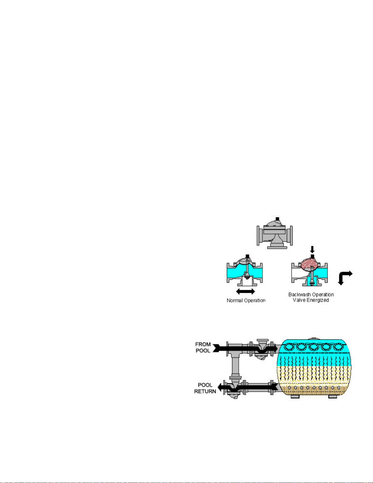
1.1 Diaphragm Valve Operation
During normal operation water enters one side of
the valve and exits the other. A shaft, which is
attached to a diaphragm at one end, and a throttling
cone and seal at the other, prevents water from
flowing out of the sideport. When the valve is
actuated, water is pumped into the top of the valve
from the controller. This water and pressure causes
the diaphragm to collapse onto the sealing surface
of the valve body. This moves the cone portion of
the shaft allowing water to exit out of the sideport,
while sealing off flow from the influent side of the
valve.
1.2 Single Tank Normal Operation
During normal filtration mode, water
is passed through the influent piping
and into the tank. Water is then
passed through the sand, which is
what actually filters the water. It is
then passed through the collection
laterals at the bottom of the tank. It
then passes out of the effluent pipe
and continues on through the rest of
the filtration system.
Diaphragm Valve Face Piping Kit Installation Manual Pg. 2 of 47
1/16/05 Rev. D
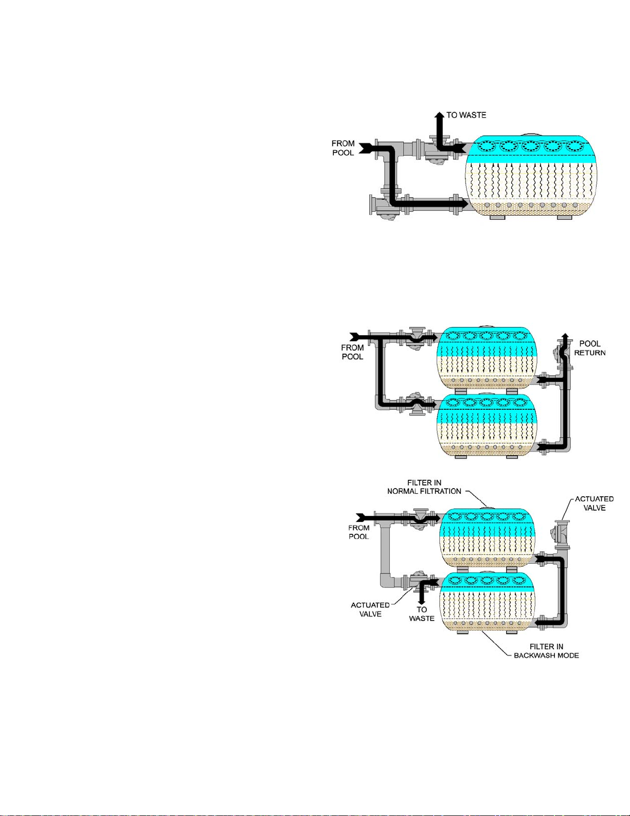
1.3 Single Tank During Backwash
During backwash mode, both of the
diaphragm valves are actuated. Since
water cannot enter the tank through
the influent piping, it enters through the
effluent piping. The water is pushed
up through the sand bed, which is
called “Fluidizing” the sand bed. This
loosens dirt and debris trapped by the
sand. This debris is then passed
through the influent piping and exits
through a waste pipe connected to the
valve.
1.4 Dual Tank Normal Filtration
During normal filtration in a dual tank
system, water is split between the two
tanks. It passes through the influent
piping and then through the sand beds.
It is then passed through the collection
laterals at the bottom of the tanks and
passed out of the effluent piping and
returned to the pool.
1.5 Dual Tank During Backwash
During backwash mode in a dual tank
system, one of the three way valves and
the two-way valve are actuated
simultaneously. This allows water to pass
through one of the filters as if it were
filtering normally. When the water exits
that tank, it is forced to enter the second
tank through the effluent pipe. This water
then backwashes the second tank. The
dirt and debris is then passed through the
influent pipe of tank two and out of a waste
pipe connected to the valve.
Diaphragm Valve Face Piping Kit Installation Manual Pg. 3 of 47
1/16/05 Rev. D
2.0 Face piping installation
IMPORTANT: Installation of the face piping should occur after the filter vessels have been
positioned in their permanent location. Please refer to the Tank Owner’s/Operator’s Manual
section on locating the filter vessels. For dual tank systems, it is very important that the “CC” dimension listed in Figure 1 on page 5 of that manual is followed. Please refer to the
Tank Owner/Operators Manual for more information.
Diaphra gm valve style face piping kits come in either one or two tank kits. All piping is pre-
glued, which means the only connections that need to be made are flanged connections between
mating sections. Please refer to the appropriate drawings in the Appendix section at the end of this
manual for aid in assembly.
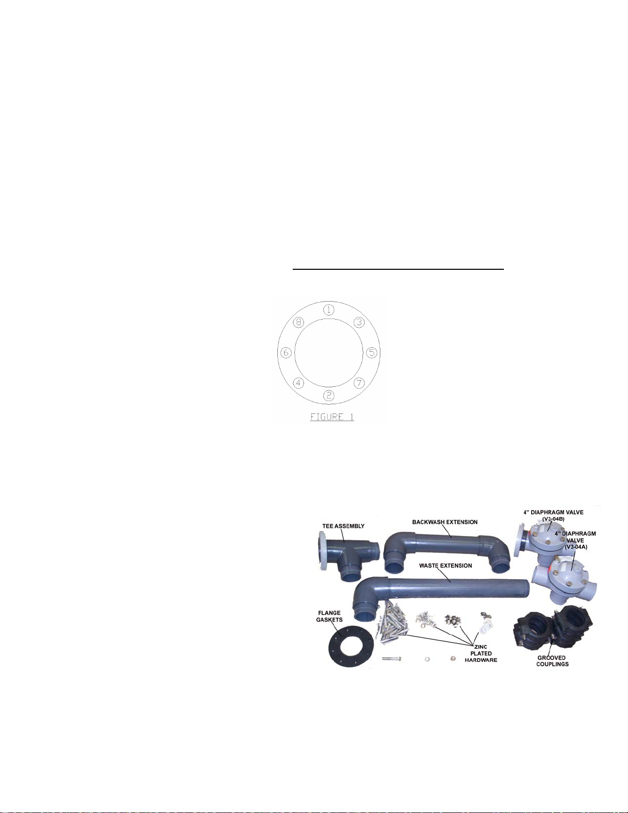
IMPORTANT: When tightening flange bolts, it is important to follow a diametrically opposed
pattern. This will ensure that a proper seal between the flanges is obtained. Refer to Figure
1 below for proper tightening sequence. Torque all bolts to a maximum of 25 ft-lbs.
may be beneficial to apply a teflon based lubricant to each bolt or nut to help relieve stress
due to friction.
Prior to Installation see “Grooved Coupling Assembly Instruction” found on page 6.
Also, it
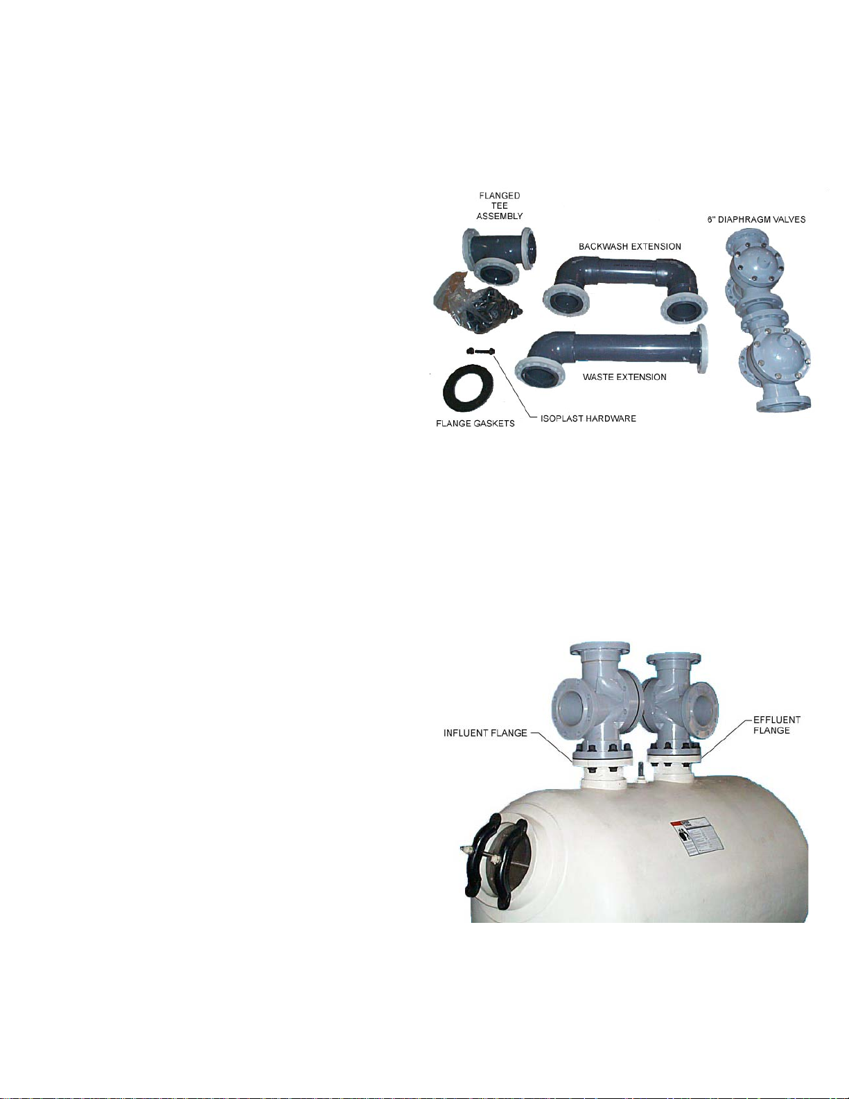
2.1 Single Tank Face Piping Installation – THS 3461 (4” Grooved
Connections)
The single tank face piping kit consists of:
(1) V3-04A, 4” 3-way diaphragm valve
without Flanges
(1) V3-04B, 4” 3-way diaphragm valve
with Flange, Thru port only.
(1) Tee Assembly
(1) Waste pipe extension
(1) Backwash extension
(1) Sightglass assembly (not shown)
(7) 4” Grooved Coupling Assembly
(3) 4” Flange gaskets
(24) 4” ¾-10 x 3 1/2” Zinc Plated Bolts
(48) Flat Washer, Zinc Plated
(24) Lock Washer, Zinc Plated
(24) Hex Nut, ¾-10, Zinc Plated
(1) Semi-automatic backwash controller
(See Controller Installation Section)
Verify that all parts listed above were supplied before beginning installation. Replacement parts
can be ordered through your local distributor.
Diaphragm Valve Face Piping Kit Installation Manual Pg. 4 of 47
1/16/05 Rev. D
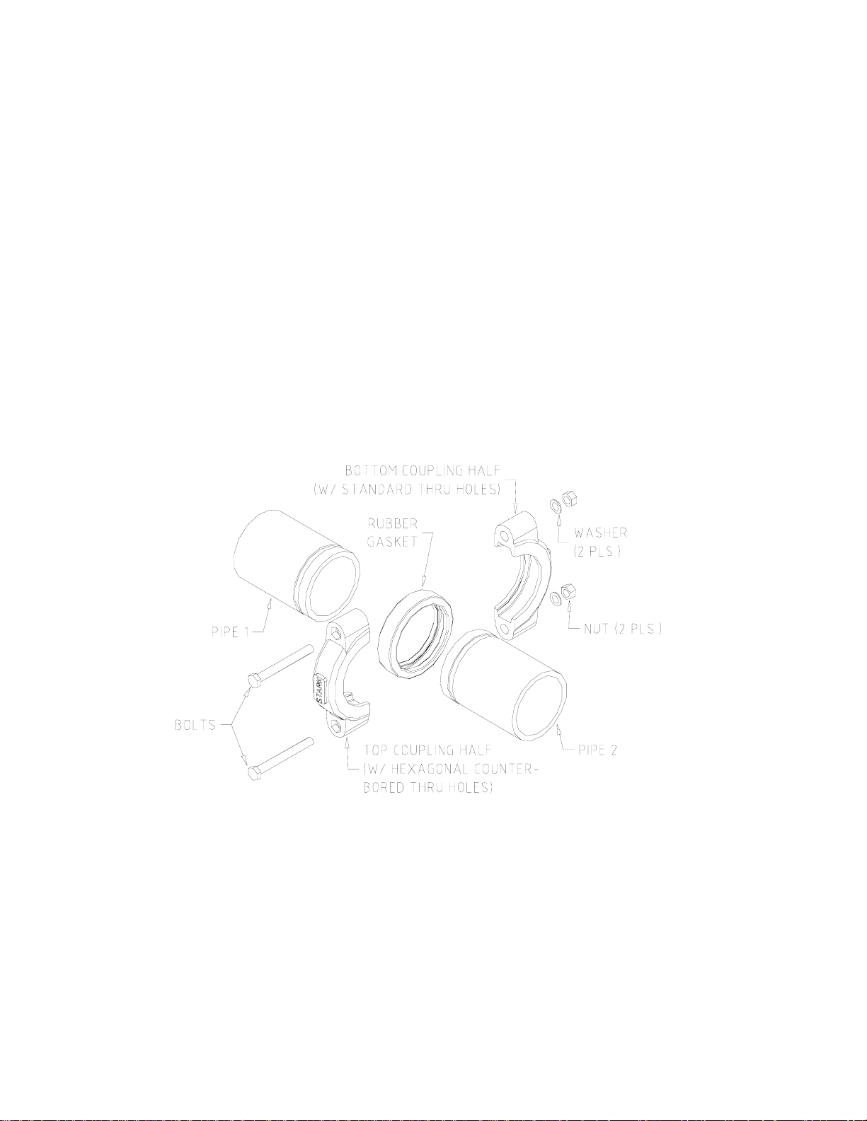
Grooved Coupling Assembly Instruction
1) Seat rubber gasket over end of pipe 1, making sure that the gasket does not cover the groove
cut in the pipe.
2) Insert end of pipe 2 into rubber gasket, again making sure that the gasket does not cover the
groove in the pipe.
3) Fit coupling halves over rubber gasket making sure that coupling halves are seated into the
grooves of the (2) pipes. Make sure one coupling half has standard thru bolt holes and the
other has hexagonal counter-bored thru bolt holes.
Apply an anti-seize lubricant to the threads of the coupling bolts. Insert bolts into the holes in the
coupling, making sure that the bolt heads fit inside the hexagonal counter-bored holes on one side
of the coupling. Place one washer and nut on each bolt and tighten.
Diaphragm Valve Face Piping Kit Installation Manual Pg. 5 of 47
1/16/05 Rev. D
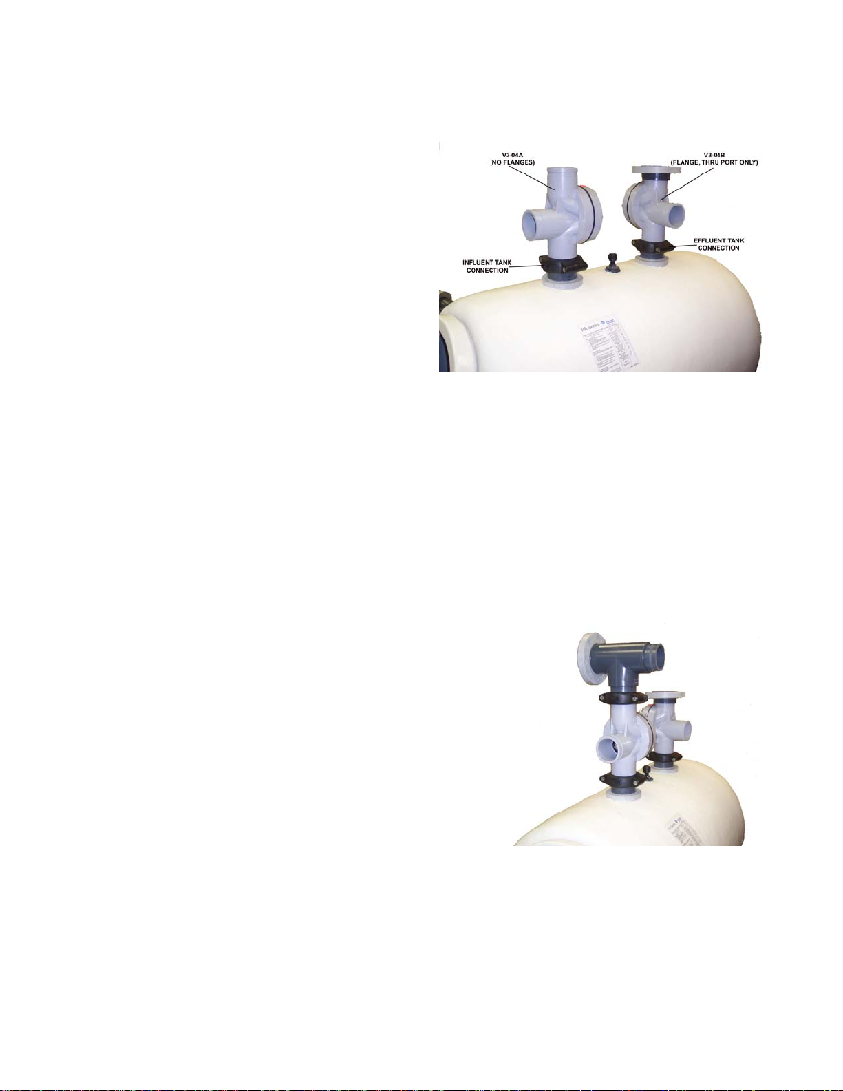
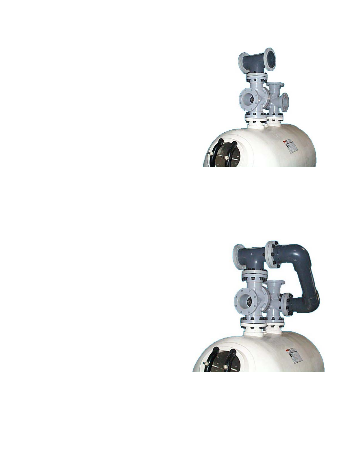
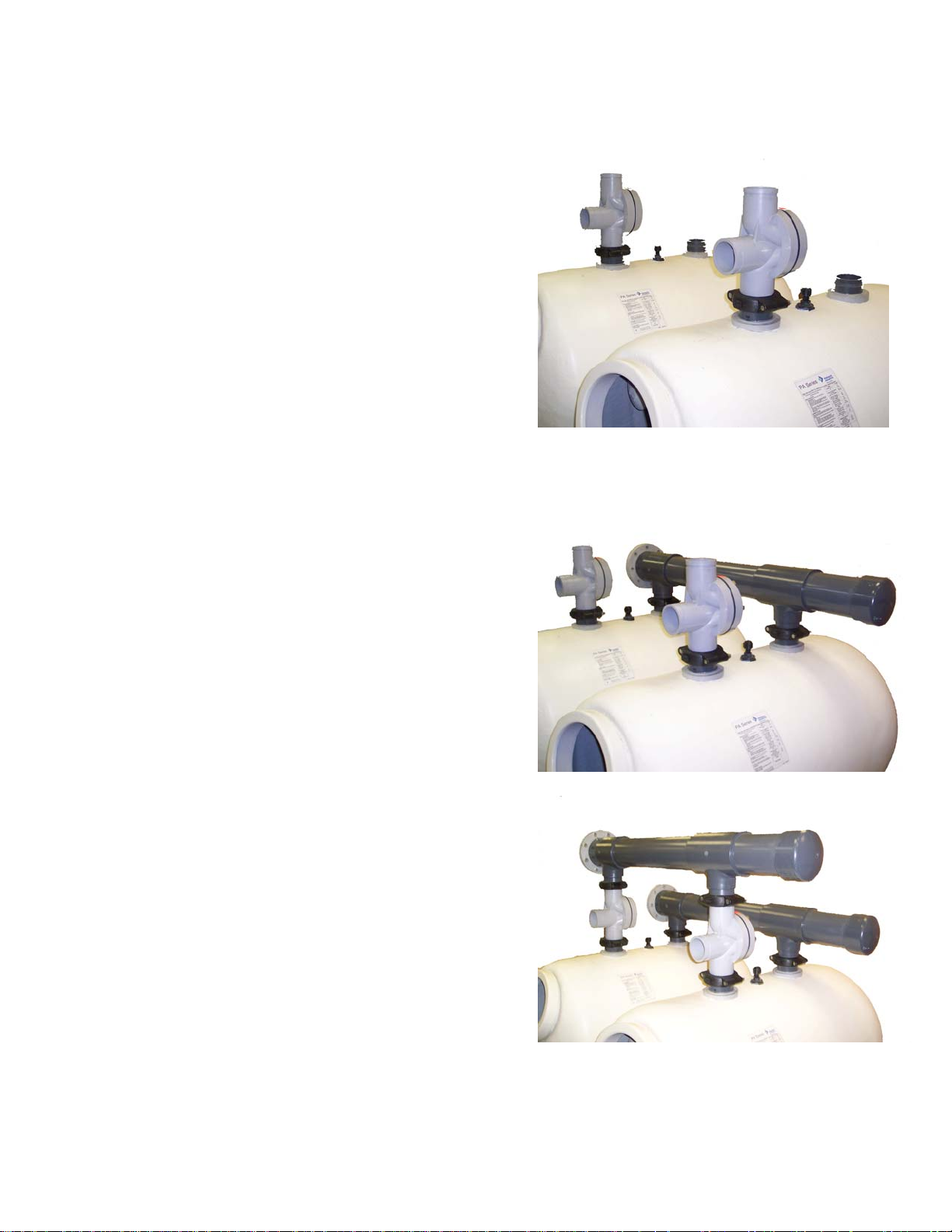
STEP 1: 4” Valve Installation
Place a gasket of grooved coupling
assembly on the influent and effluent tank
grooved pipe connections. Place valve (V3-
04A) with no flanges on influent grooved
pipe connection, install groove coupling
assembly (Refer to page 5). Place valve
(V3-04B) with flange on thru port on effluent
grooved pipe connection, install groove
coupling assembly. See picture at right for
proper orientation. Snug the nuts to “hand
tight”, but do not fully tighten. This will allow
for adjustments during the remainder of the
installation. Please note the orientation of
the valves. The arrows on the valve
covers should be pointing toward the
STEP 2: Tee Assembly Installation
Place gasket of grooved coupling assembly on top
grooved connection of the influent valve. Install the
Tee assembly on the top of the influent valve, and
orient it as shown in picture, install groove coupling
assembly. Snug the nuts to “hand tight”, but do not
fully tighten.
tank.
Diaphragm Valve Face Piping Kit Installation Manual Pg. 6 of 47
1/16/05 Rev. D
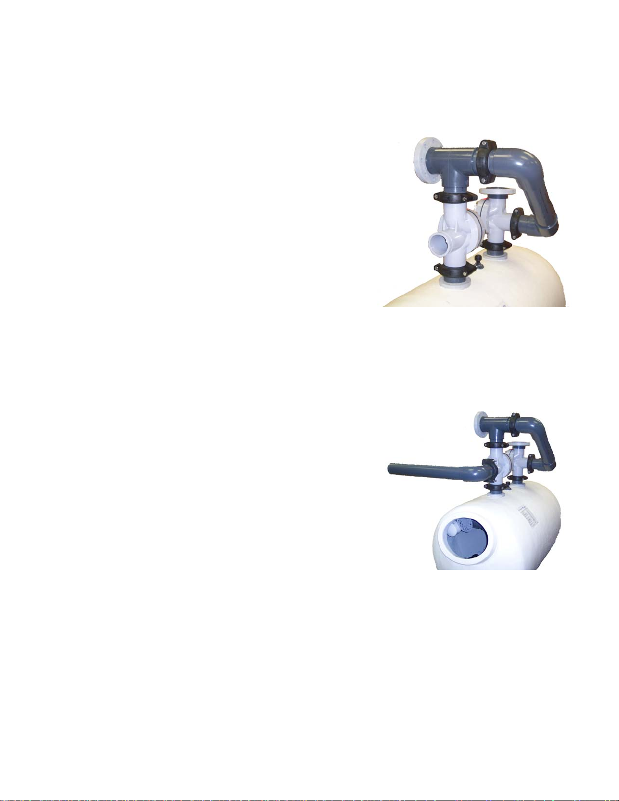
STEP 3: Backwash Extension Installation
Place gasket of grooved coupling assembly on grooved
connection of the Tee assembly along with the effluent
valve. Install the backwash extension on to the system
as shown in picture. It may be necessary to turn the
valves or tee assembly slightly to ensure a proper fit.
Install groove coupling assembly. Snug the nuts to “hand
tight”, but do not fully tighten.
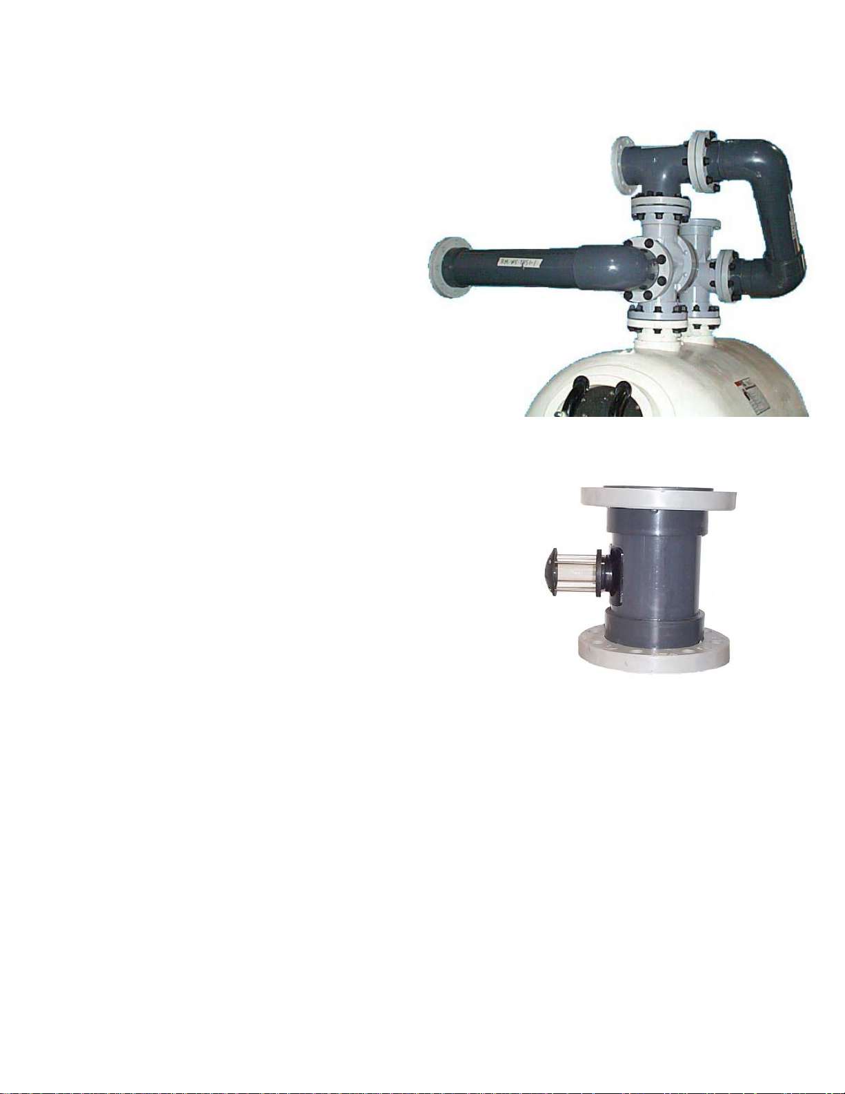
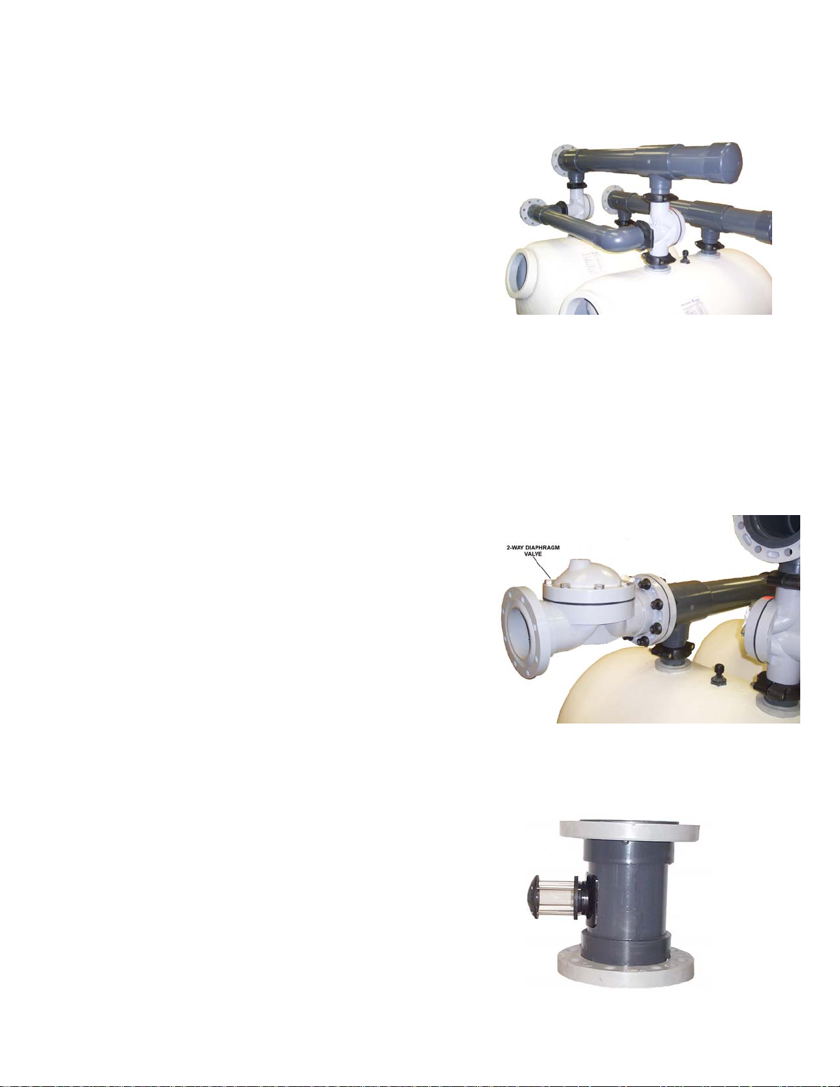
STEP 4: Waste Extension Installation
Place gasket of grooved coupling assembly on grooved
connection of influent valve. Install the waste extension
on to the system as shown in picture. Install groove
coupling assembly. Snug the nuts to “hand tight”, but do
not fully tighten.
Diaphragm Valve Face Piping Kit Installation Manual Pg. 7 of 47
1/16/05 Rev. D
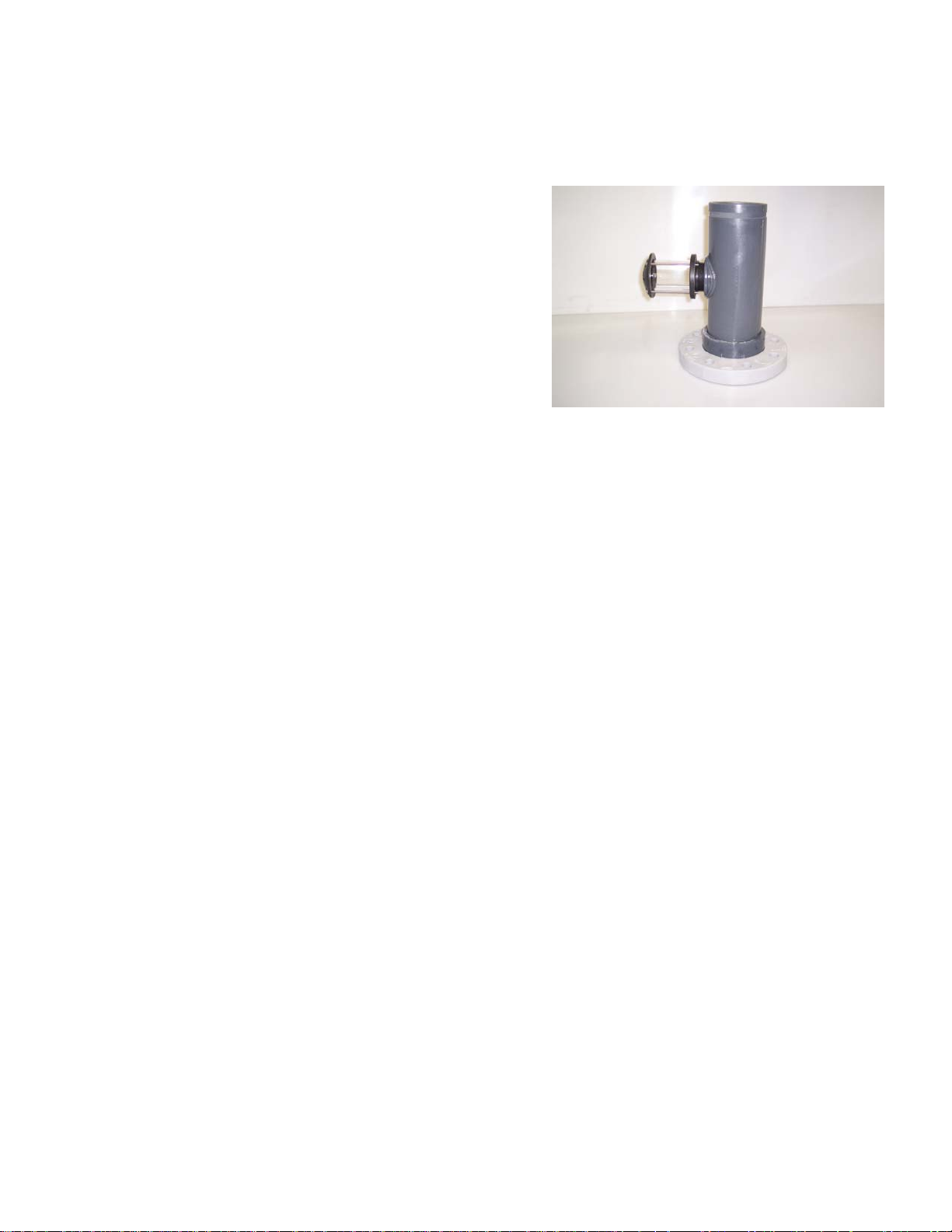
STEP 5: Sightglass Installation
Assemble the sightglass by threading the glass
portion into the threaded saddle on the spool. Be
sure to use pipe thread sealant tape on the threads.
Place gasket of grooved coupling assembly on to the
waste extension Install the sightglass assembly on to
the waste flange. Orient the glass portion so it will be
visible during operation. Install groove coupling
assembly. Snug the nuts to “hand tight”, but do not
fully tighten.
STEP 6: Final Adjustments
Once all piping is in place make any necessary adjustments and fully tighten all flange bolts.
Be sure to follow the bolt tightening pattern explained at the beginning of Section 2.0. Tighten
all bolts to a maximum of 40 ft-lbs.
Note: All piping should be fully supported with adequate bracing and hangers
to prevent damage from weight and vibration.
STEP 7: Backwash Controller Installation
If a semi-automatic backwash controller was purchased, please refer to Section 3.1 of this
manual. If an automatic backwash controller was purchased, please refer to Section 3.3.
NOTE: There will be extra gaskets and isoplast hardware. This is to join the remaining
flanged connections of the filter system to any existing or new plumbing.
Diaphragm Valve Face Piping Kit Installation Manual Pg. 8 of 47
1/16/05 Rev. D
2.2 Single Tank Face Piping Installation – THS 3484, THS4272, THS
4284 and THS 4296 (6” Flange Connections)
The single tank face piping kit consists of:
(2) 6” 3-way diaphragm valves
(1) Waste pipe extension
(2) Backwash extension
(1) Sightglass assembly (not shown)
(3) 6” Flange
gaskets
(80) Isoplast bolts
(80) Isoplast nuts
(2) Semi-automatic backwash controller
(See Controller Installation Section)
Verify that all parts listed above were supplied before beginning installation. Replacement
parts can be ordered through your local distributor.
STEP 1: 6” Valve Installation
Place a flange gasket on the influent and
effluent tank flanges. Align the holes in the
gasket with the holes in the flange ring on
the tank. Place valves on the flanges
aligning the holes on the valve flange with
the tank flange ring. Please note the
orientation of the valves. The arrows on
the valve covers should be pointing
toward the tank. Install isoplast bolts and
nuts on the influent and effluent flanges.
Snug the nuts to “hand tight”, but do not
fully tighten. This will allow for adjustments
during the remainder of the installation.
Diaphragm Valve Face Piping Kit Installation Manual Pg. 9 of 47
1/16/05 Rev. D
STEP 2: Flanged Tee Assembly Installation
Place gasket on top flange of the influent valve.
Install the flanged tee assembly on the top of the
influent valve, and orient it as shown in picture.
Install isoplast bolts and nuts. Snug the nuts to
“hand tight”, but do not fully tighten.
STEP 3: Backwash Extension Installation
Place isoplast bolts through the bolt holes on
the backwash extension flanges, then place
flange gaskets on to the flanges with the bolts.
Install the backwash extension on to the
system as shown in picture. It may be
necessary to turn the valves or flanged tee
assembly slightly to ensure a proper fit. Install
isoplast nuts. Snug the nuts to “hand tight”,
but do not fully tighten.
Diaphragm Valve Face Piping Kit Installation Manual Pg. 10 of 47
1/16/05 Rev. D
STEP 4: Waste Extension Installation
Place isoplast bolts through bolt holes
on the waste extension flange (elbow
side), then place a flange gasket onto
the flange. Install waste extension onto
valve making sure it is oriented properly
with the flange on the elbow connecting
to the valve (see picture). Install
isoplast nuts. Snug the nuts to “hand
tight”, but do not fully tighten.
STEP 5: Sightglass Installation
Assemble the sightglass by threading the glass portion into
the threaded saddle on the spool. Be sure to use pipe
thread sealant tape on the threads. Place isoplast bolts
through flange on the waste header, then place a flange
gasket on to the flange. Install the sightglass assembly on to
the waste flange. Orient the glass portion so it will be visible
during operation. Install isoplast nuts and snug them to
“hand tight”, but do not fully tighten.
STEP 6: Final Adjustments
Once all piping is in place make any necessary adjustments and fully tighten all flange bolts.
Be sure to follow the bolt tightening pattern explained at the beginning of Section 2.0. Tighten
all bolts to a maximum of 40 ft-lbs.
Note: All piping should be fully supported with adequate bracing and hangers
to prevent damage from weight and vibration.
STEP 7: Backwash Controller Installation
If a semi-automatic backwash controller was purchased, please refer to Section 3.1 of this
manual. If an automatic backwash controller was purchased, please refer to Section 3.3.
NOTE: There will be extra gaskets and isoplast hardware. This is to join the remaining
flanged connections of the filter system to any existing or new plumbing.
Diaphragm Valve Face Piping Kit Installation Manual Pg. 11 of 47
1/16/05 Rev. D
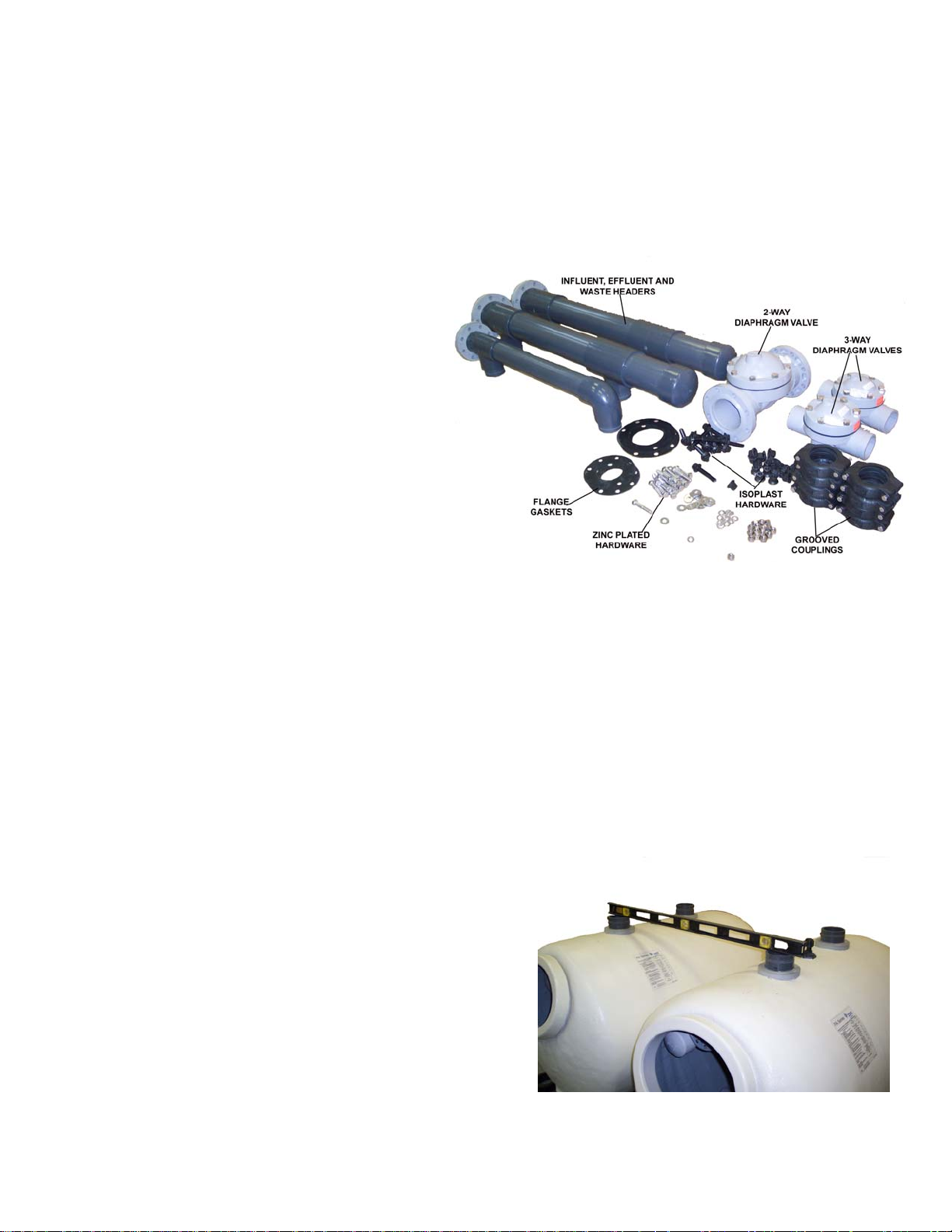
2.3 Dual Tank Face Piping Installation – THS 3461 (4” Grooved Tank
Connections)
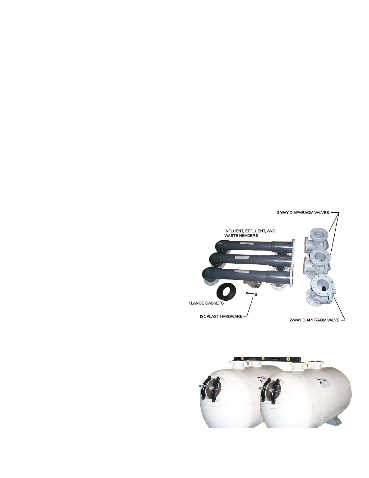
The two tank face piping kit consists of:
(2) 4” 3-way diaphragm valves
(1) 6” 2-way diaphragm valve
(2) Influent/effluent headers
(1) Waste header
(1) Sightglass assembly (not shown)
(4) 4” Grooved Coupling Assembly
(2) 4” Flange gaskets
(2) 6” Flange gaskets
(24) Isoplast bolts
(24) Isoplast nuts
(16) 4” ¾-10 x 3 1/2” Zinc Plated Bolts
(32) Flat Washer, Zinc Plated
(16) Lock Washer, Zinc Plated
(16) Hex Nut, ¾-10, Zinc Plated
(1) Semi-automatic backwash
controller (See Controller
Installation Section)
Verify that all parts listed above were supplied before beginning installation. Replacement
parts can be ordered through your local distributor.
Prior to Installation see “Grooved Coupling Assembly Instruction” found on page 5.
IMPORTANT: Verify that the center to center dimension between the two tanks is correct.
Refer to Figure 1 on page 5 of the Tank Owner’s/Operator’s Manual for more information.
STEP 1: Level the tanks
Make sure influent and effluent flanges on each
tank are level. Shimming may be required to bring
the tanks to level with each other. Use a noncompressible material placed under the tank
saddles. Further leveling may require the saddles
to be adjusted. Please refer to page 5 of the Tank
Owner’s/Operator’s Manual for more information.
Diaphragm Valve Face Piping Kit Installation Manual Pg. 12 of 47
1/16/05 Rev. D
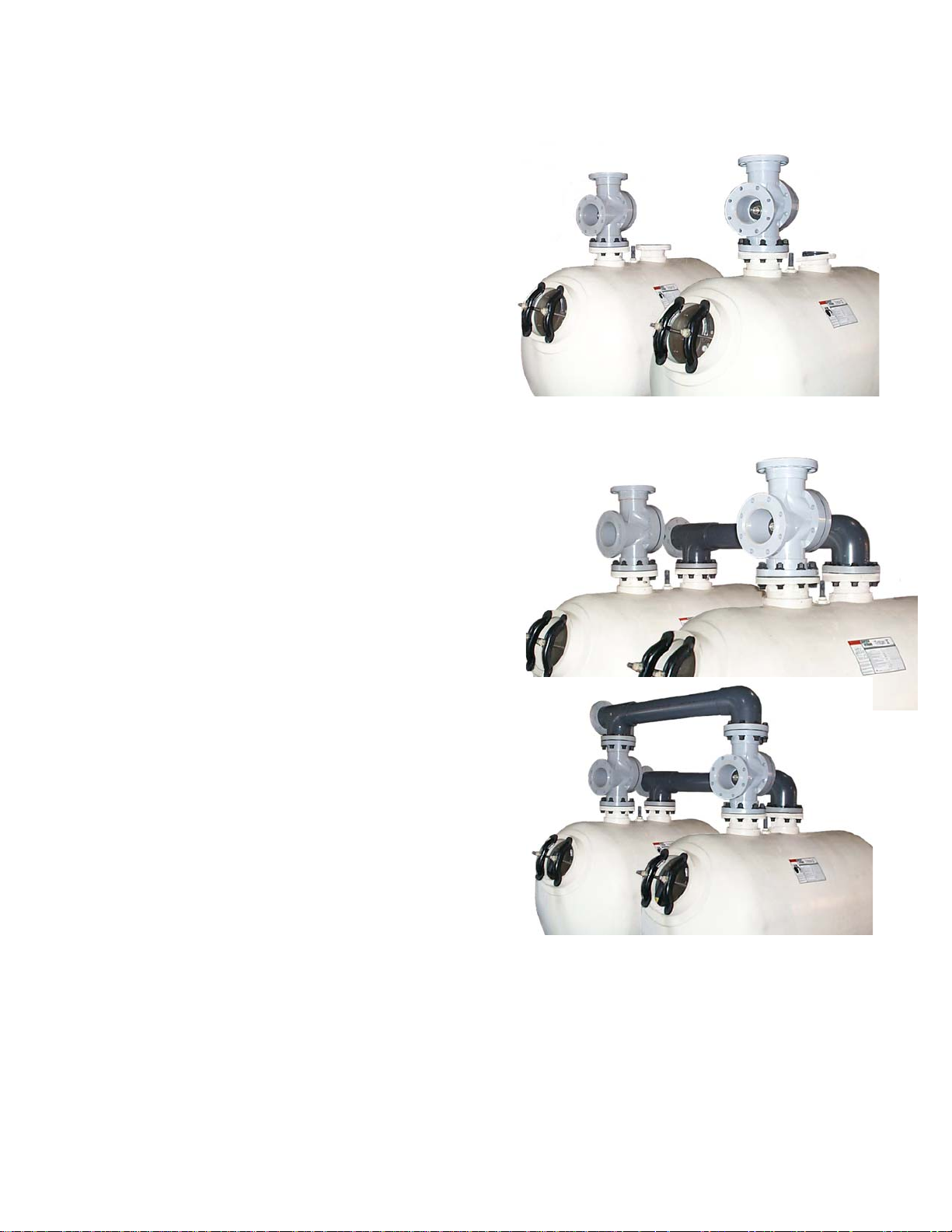
STEP 2: 4” 3-way Valve Installation
Place a gasket of grooved coupling assembly on
the influent grooved pipe connection of each tank.
Place valves on influent grooved pipe
connections, install groove coupling
assembly(Refer to page 5). See picture at right for
proper orientation. Snug the nuts to “hand tight”,
but do not fully tighten. This will allow for
adjustments during the remainder of the
installation. Please note the orientation of the
valves. The arrows on the valve covers should
be pointing toward the tank.
STEP 3: Influent/Effluent Header Installation
Place a gasket of grooved coupling assembly on
top grooved connection of each valve and the
effluent grooved pipe connection of each tank.
Install headers on to the valve/tank connections
(see pictures). Install groove coupling assembly.
The headers can be installed with the terminating
flange facing either left or right depending on what
is needed for the application. Snug the nuts to
“hand tight”, but do not fully tighten. This will allow
for adjustments during the remainder of the
installation.
Diaphragm Valve Face Piping Kit Installation Manual Pg. 13 of 47
1/16/05 Rev. D
STEP 4: Waste Header Installation
Place gasket of grooved coupling assembly on
grooved connection of influent valves. Install the waste
extension on to the system as shown in picture. Install
groove coupling assembly. Snug the nuts to “hand
tight”, but do not fully tighten.
STEP 5: 6” 2-way Valve Installation
Place isoplast bolts through the flange on the
effluent header, then place a flange gasket on to the
flange. Install the valve on to the flanges making
sure to align the flange holes with the bolts. The
arrow on the valve cover should be pointing
away from the tank, in the direction of the
effluent flow. Install isoplast nuts. Snug the nuts to
“hand tight”, but do not fully tighten.
STEP 6: Sightglass Installation
Assemble the sightglass by threading the glass portion into
the threaded saddle on the spool. Be sure to use pipe
thread sealant tape on the threads. Place isoplast bolts
through flange on the waste header, then place a flange
gasket on to the flange. Install the sightglass assembly on
to the waste flange. Orient the glass portion so it will be
visible during operation. Install isoplast nuts and snug
them to “hand tight”, but do not fully tighten.
Diaphragm Valve Face Piping Kit Installation Manual Pg. 14 of 47
1/16/05 Rev. D
STEP 7: Final Adjustments
Once all piping is in place make any necessary adjustments and fully tighten all flange bolts.
Be sure to follow the bolt tightening pattern explained at the beginning of Section 2.0. Tighten
all bolts to a maximum of 25 ft-lbs.
Note: All piping should be fully supported with adequate bracing and hangers
to prevent damage from weight and vibration.
STEP 8: Backwash Controller Installation
If a semi-automatic backwash controller was purchased, please refer to Section 3.2 of this
manual. If an automatic backwash controller was purchased, please refer to Section 3.4.
NOTE: There will be extra gaskets and isoplast hardware. This is to join the remaining
flanged connections of the filter system to any existing or new plumbing.
2.4 Dual Tank Face Piping Installation – THS 3484, THS4272, THS 4284 and
THS 4296 (6” Flange Connections)
The two tank face piping kit consists of:
(2) 6” 3-way diaphragm valves
(1) 6” 2-way diaphragm valve
(2) Influent/effluent headers
(1) Waste header
(1) Sightglass assembly (not shown)
(13) 6” Flange gaskets
(104) Isoplast bolts
(104) Isoplast nuts
(2) Semi-automatic backwash controller
(See Controller Installation Section)
Verify that all parts listed above were
supplied before beginning installation.
Replacement parts can be ordered
through your local distributor.
IMPORTANT: Verify that the center to center dimension between the two tanks is correct.
Refer to Figure 1 on page 5 of the Tank Owner’s/Operator’s Manual for more information.
STEP 1: Level the tanks
Make sure influent and effluent flanges on
each tank are level. Shimming may be
required to bring the tanks to level with each
other. Use a non-compressible material
placed under the tank saddles. Further
leveling may require the saddles to be
adjusted. Please refer to page 5 of the Tank
Owner’s/Operator’s Manual for more
information.
Diaphragm Valve Face Piping Kit Installation Manual Pg. 15 of 47
1/16/05 Rev. D
STEP 2: 6” 3-way Valve Installation
Place a flange gasket on the influent flange
of each tank. Align the holes in the gasket
with the holes in the flange on the tank.
Place valves on the influent flanges aligning
the holes on the valve flange with the tank
flange. Please note the orientation of the
valves. The arrows on the valve covers
should be pointing toward the tank. Install
isoplast bolts and nuts on the influent flanges
of each tank. Snug the nuts to “hand tight”,
but do not fully tighten. This will allow for
adjustments during the remainder of the
installation
STEP 3: Influent/Effluent Header Installation
Place flange gaskets on the top flanges of the
valves and on the effluent flanges of the tanks.
Align the holes in the gaskets with the holes in
the flanges. Install headers on to the valve/tank
flanges (see picture). The headers can be
installed with the terminating flange facing either
left or right depending on what is needed for the
application. Install isoplast bolts and nuts on the
flanges of the headers. Snug the nuts to “hand
tight”, but do not fully tighten.
Diaphragm Valve Face Piping Kit Installation Manual Pg. 16 of 47
1/16/05 Rev. D

STEP 4: Waste Header Installation
Place isoplast bolts through the flanges on the waste
header, then place flange gaskets on to the flanges
with the bolts. Install the waste header on to the
remaining valve flanges making sure to align the
flange holes with the bolts. It may be necessary to
turn the valves slightly to ensure a proper fit. Install
isoplast nuts. Snug the nuts to “hand tight”, but do not
fully tighten.
STEP 5: 6” 2-way Valve Installation
Place isoplast bolts through the flange on the effluent
header, then place a flange gasket on to the flange.
Install the valve on to the flanges making sure to align
the flange holes with the bolts. The arrow on the
valve cover should be pointing away from the tank,
in the direction of the effluent flow. Install isoplast
nuts. Snug the nuts to “hand tight”, but do not fully
tighten.
STEP 6: Sightglass Installation
Assemble the sightglass by threading the glass portion into
the threaded saddle on the spool. Be sure to use pipe
thread sealant tape on the threads. Place isoplast bolts
through flange on the waste header, then place a flange
gasket on to the flange. Install the sightglass assembly on
to the waste flange. Orient the glass portion so it will be
visible during operation. Install isoplast nuts and snug
them to “hand tight”, but do not fully tighten.
STEP 7: Final Adjustments
Once all piping is in place make any necessary adjustments and fully tighten all flange bolts.
Be sure to follow the bolt tightening pattern explained at the beginning of Section 2.0. Tighten
all bolts to a maximum of 25 ft-lbs.
Diaphragm Valve Face Piping Kit Installation Manual Pg. 17 of 47
1/16/05 Rev. D

STEP 8: Backwash Controller Installation
If a semi-automatic backwash controller was purchased, please refer to Section 3.2 of this
manual. If an automatic backwash controller was purchased, please refer to Section 3.4.
NOTE: There will be extra gaskets and isoplast hardware. This is to join the remaining
flanged connections of the filter system to any existing or new plumbing.
Diaphragm Valve Face Piping Kit Installation Manual Pg. 18 of 47
1/16/05 Rev. D

3.0 Backwash Controller Installation
NOTE: This section covers the installation of semi-automatic and automatic backwash
controllers for single and dual tank systems.
3.1 Single Tank Semi-automatic Controller Installation
The single tank semi-automatic backwash
controller consists of:
(1) Controller gauge panel
(2) 3/8” OD tube quick connect tees
(3) 3/8” OD x ¼” MNPT quick connect
fittings
(1) Check valve w/ fittings
(1) Adjustable pressure regulator
(100 ft) 3/8” OD polyethylene tube
(2 pr.) Mounting brackets and hardware
(2) Controller supports
(2) Isoplast bolts
(2) Isoplast nuts
Verify that all parts listed above were supplied
before beginning installation. Replacement parts
can be ordered through the manufacturer.
Diaphragm Valve Face Piping Kit Installation Manual Pg. 19 of 47
1/16/05 Rev. D

STEP 1: Controller Support Assembly
Attach controller supports t o the gauge panel assembly
using the ¾” isoplast nuts and bolts. Attach so the
channel side of the supports is away from the gauge
panel. Tighten bolts, but do not over tighten, this may
crack the face of the gauge panel.
Diaphragm Valve Face Piping Kit Installation Manual Pg. 20 of 47
1/16/05 Rev. D

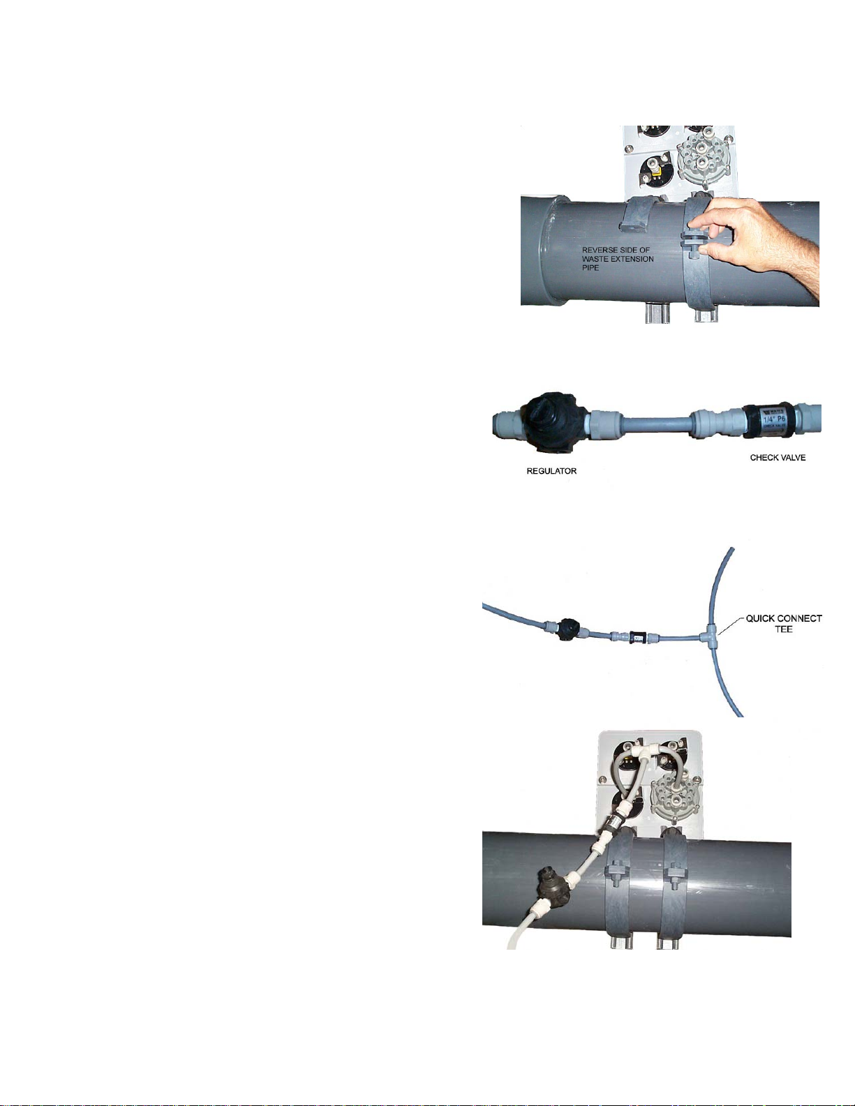
STEP 2: Attach Gauge Panel to System
Insert notched end of pipe clamps into the channel of
the controller supports. Attach the gauge panel
assembly to the waste extension (see picture). Slide
remaining pipe clamps into the channels of the controller
supports. Use the nuts and bolts supplied to tighten the
clamps on to the pipe.
STEP 3: Installation of Controller Tubing
Connect the regulator with the check valve
assembly with a section of 3/8” OD tube. Please
note the direction of the flow arrow on the check
valve. It should be pointing away from the
regulator.
Connect length of tubing to open end of the
check valve. Connect quick connect tee to end
of tube. On both open ends of the quick connect
tee connect tubing as shown in picture.
Connect tubes from the quick connect tee to back
of gauge panel assembly as shown in picture.
One end should be connected to the center fitting
on the multiport valve, the other should be
connected to the multiport pressure gauge.
Connect open end of tubing from the regulator to
your city water supply, or other water source. An
extra 3/8" x 1/4" MNPT fitting has been provided
for connection. Please note, the water source
must be able to supply water at a pressure of
35 psi minimum.
Diaphragm Valve Face Piping Kit Installation Manual Pg. 21 of 47
1/16/05 Rev. D

Drill and tap for ¼” NPT hole on the influent and
effluent pipes from the filter system (see
schematic diagram in Appendix B). Install quick
connect fittings into pipe. Be sure to use pipe
thread sealant tape on threads. Install 3/8” OD
tube from fittings to rear of gauge panel assembly.
Connect tubes into correct gauge on rear of panel
(see picture).
Connect lengths of tubing into the quick connect
fittings on top of the valve cover. Join these two
tubes with a quick connect tee as shown in the
picture.
Connect a length of tube from open end of quick
connect tee from the valves to the fitting on the
back of the gauge panel assembly as shown in
the picture. Connect tube from remaining quick
connect fitting and connect to drain.
Diaphragm Valve Face Piping Kit Installation Manual Pg. 22 of 47
1/16/05 Rev. D

This completes the installation of the semi-automatic backwash controller for single tank
systems. Please proceed to Section 4.0 for operating instructions.
3.2 Dual Tank Semi-Automatic
Controller Installation
The dual tank semi-automatic controller kit
consists of the following:
(1) Controller gauge panel
(3) 3/8” OD tube quick connect tees
(3) 3/8” OD x ¼” MNPT quick connect
fittings
(1) Check valve w/ fittings
(1) Adjustable pressure regulator
(1) And/Or Valve
(100 ft) 3/8” OD polyethylene tube
(2pr.) Mounting brackets and hardware
(2) Controller supports
(2) Isoplast bolts
(2) Isoplast nuts
Verify that all parts listed above were
supplied before beginning installation.
Replacement parts can be ordered through
the manufacturer.
Diaphragm Valve Face Piping Kit Installation Manual Pg. 23 of 47
1/16/05 Rev. D

STEP 1: Controller Support Assembly
Attach controller supports to the gauge panel
assembly using the ¾” isoplast nuts and bolts. Attach
so the channel side of the supports is away from the
gauge panel. Tighten bolts, but do not over tighten,
this may crack the face of the gauge panel.
Diaphragm Valve Face Piping Kit Installation Manual Pg. 24 of 47
1/16/05 Rev. D
STEP 2: Attach Gauge Panel to System
Insert notched end of pipe clamps into the channel of
the controller supports. Attach the gauge panel
assembly to the waste extension (see picture). Slide
remaining pipe clamps into the channels of the controller
supports. Use the nuts and bolts supplied to tighten the
clamps on to the pipe.
STEP 3: Installation of Controller Tubing
Connect the regulator with the check valve
assembly with a section of 3/8” OD tube. Please
note the direction of the flow arrow on the check
valve. It should be pointing away from the
regulator.
Connect length of tubing to open end of the
check valve. Connect quick connect tee to end of
tube. On both open ends of the quick connect tee
connect tubing as shown in picture.
Connect tubes from the quick connect tee to back
of gauge panel assembly as shown in picture.
One end should be connected to the center fitting
on the multiport valve, the other should be
connected to the multiport pressure gauge.
Connect open end of tubing from the regulator to
your city water supply, or other water source. An
extra 3/8" x 1/4" MNPT fitting has been provided
for connection. Please note, the water source
must be able to supply water at a pressure of
35 psi minimum.
Diaphragm Valve Face Piping Kit Installation Manual Pg. 25 of 47
1/16/05 Rev. D

Drill and tap for ¼” NPT hole on the influent and
effluent pipes from the filter system (see
schematic diagram in Appendix B). Install quick
connect fittings into pipe. Be sure to use pipe
thread sealant tape on the threads. Install 3/8”
OD tube from fittings to rear of gauge panel
assembly. Connect tubes in to correct gauge on
rear of panel (see picture).
Assemble the And/Or assembly shown
in the picture (above right). Be sure to
leave enough tubing to reach all of the
necessary connections. Connect all tubes to
their appropriate locations as explained in the
picture.
Diaphragm Valve Face Piping Kit Installation Manual Pg. 26 of 47
1/16/05 Rev. D

Connect length of tube into remaining fitting on gauge panel assembly. Connect this to the
drain. Please note, And/Or assembly note shown for clarity.
This completes the installation of the semi-automatic backwash controller for single tank
systems. Please proceed to Section 4.0
for operating instructions.
3.3 Single Tank Automatic
Controller Installation
The single tank automatic backwash
controller consists of:
(1) Automatic controller enclosure
(1) Multiport valve enclosure
(4) 3/8” OD tube quick connect tees
(3) 3/8” OD x ¼” MNPT quick connect
fittings
(1) Check valve w/ fittings
(100 ft) 3/8” OD polyethylene tube
(4pr.) Mounting brackets and hardware
(1) Owner’s/Operator’s manual for
automatic controller
Verify that all parts listed above were supplied before beginning installation. Replacement
parts can be ordered through the manufacturer.
Diaphragm Valve Face Piping Kit Installation Manual Pg. 27 of 47
1/16/05 Rev. D

STEP 1: Attach Controller/Multiport Enclosures to Piping
Insert notched end of pipe clamps
into the channel of the enclosure
supports. Attach the enclosure
assemblies to the waste extension
(see picture). Slide remaining pipe
clamps into the channels of the
enclosure supports. Use the nuts and
bolts supplied to tighten the clamps on
to the pipe.
STEP 2: Installation of Controller Tubing
Insert length of 3/8” tube into top fitting on
the regulator (see picture). Connect other
end of this tube to your city water supply, or
other water source. An extra 3/8" x 1/4"
MNPT fitting has been provided for
connection. Please note, the water source
must be able to supply water at a
pressure of 35 psi minimum. Connect the
check valve to the other fitting from the
regulator with a small length of tubing. Make
sure that the arrow on the check valve is
pointed away from the regulator. From the
other end of the check valve connect a length
of tube and attach a quick connect tee fitting
(see picture).
Connect tubes to each side of the quick
connect tee. Connect one tube to the
multiport pressure gauge and the other to the
center fitting on the multiport valve (see
picture).
Diaphragm Valve Face Piping Kit Installation Manual Pg. 28 of 47
1/16/05 Rev. D

Drill and tap for ¼” NPT hole on the influent
and effluent pipes from the filter system (see
schematic diagram in Appendix B). Install
quick connect fittings in to holes. Be sure to
use pipe thread sealant tape on the
threads. Install into each fitting a length of
3/8” OD tubing. Connect a quick connect tee
on to the other end of each tube. Connect
two smaller pieces of tubing into each tee
and connect to the rear of the automatic
controller enclosure as shown.
Connect lengths of tubing into the quick connect
fittings on top of the valve cover. Join the two
tubes with a quick connect tee as shown in the
picture.
Connect a length of tube from open end of quick
connect tee from the valves to the fitting on the
back of the gauge panel assembly as shown in
the picture. Connect tube from remaining quick
connect fitting and connect to drain.
Diaphragm Valve Face Piping Kit Installation Manual Pg. 29 of 47
1/16/05 Rev. D

Connect the four wires from the rear of the multiport valve enclosure to the rear of the
automatic controller enclosure. Each wire has a different style pin connector and can only
connect to one of the sockets on the back of the automatic controller enclosure.
This completes the installation of the automatic backwash controller for single tank systems.
Please see Owner’s/Operater’s Manual for automatic controller set up and operation.
3.4 Dual Tank Automatic
Controller Installation
The dual tank automatic controller kit
consists of the following:
(1) Automatic controller enclosure
(1) Multiport valve enclosure
(5) 3/8” OD tube quick connect tees
(3) 3/8” OD x ¼” MNPT quick connect
fittings
(1) Check valve w/ fittings
(1) And/Or Valve
(100 ft) 3/8” OD polyethylene tube
(4pr.) Mounting brackets and hardware
(1) Owner’s/Operators manual for
automatic backwash controller
Verify that all parts listed above were supplied before beginning installation. Replacement
parts can be ordered through the manufacturer.
STEP 1: Attach Controller/Multiport Enclosures to Piping
Insert notched end of pipe clamps
into the channel of the enclosure
supports. Attach the enclosure
assemblies to the waste extension
(see picture). Slide remaining pipe
clamps into the channels of the
enclosure supports. Use the nuts and
bolts supplied to tighten the clamps on
to the pipe.
Diaphragm Valve Face Piping Kit Installation Manual Pg. 30 of 47
1/16/05 Rev. D

STEP 2: Installation of Controller Tubing
Insert length of 3/8” tube into top fitting on
the regulator (see picture). Connect other end
of this tube to your city water supply, or other
water source. An extra 3/8" x 1/4" MNPT
fitting has been provided for connection.
Please note, the water source must be able
to supply water at a pressure of 35 psi
minimum. Connect the check valve to the
other fitting from the regulator with a small
length of tubing. Make sure that the arrow on
the check valve is pointed away from the
regulator. From the other end of the check
valve connect a length of tube and attach a
quick connect tee fitting (see picture).
Connect tubes to each side of the quick
connect tee. Connect one tube to the
multiport pressure gauge and the other to the
center fitting on the multiport valve (see
picture).
Drill and tap for ¼” NPT hole on the influent
and effluent pipes from the filter system (see
schematic diagram in Appendix B). Install
quick connect fittings in to holes. Be sure to
use pipe thread sealant tape on the
threads. Install into each fitting a length of
3/8” OD tubing. Connect a quick connect tee
on to the other end of each tube. Connect
two smaller pieces of tubing into each tee
and connect to the rear of the automatic
controller enclosure as shown.
Diaphragm Valve Face Piping Kit Installation Manual Pg. 31 of 47
1/16/05 Rev. D

Assemble the And/Or assembly shown in
the picture (above right). Be sure to leave
enough tubing to reach all of the
necessary connections. Connect all tubes
to their appropriate locations as explained
in the picture. Connect tube from
remaining quick connect fitting and
connect to drain.
Connect the four wires from the rear of the
multiport valve enclosure to the rear of the
automatic controller enclosure. Each wire has a
different style pin connector and can only
connect to one of the sockets on the back of the
automatic controller enclosure.
This completes the installation of the automatic backwash controller for dual tank systems.
Please see Owner’s/Operater’s Manual for automatic controller set up and operation.
Diaphragm Valve Face Piping Kit Installation Manual Pg. 32 of 47
1/16/05 Rev. D

4.0 Operation
The diaphragm valve style face piping kits are designed for simple operation and
maintenance. Backwashing is accomplished by turning a single knob to actuate the
diaphragm valves. The automatic controller can be set up to backwash automatically
dependant on certain chosen parameters, as well manually if required (refer to automatic
controller manual for more information). The systems backwash one tank at a time, and in
the case of the dual tank systems, each tank is backwashed with clean, filtered water.
The following section will explain briefly how to set the multiport pressure, when to
backwash the tanks, how the controllers work, how to initiate a backwash cycle, and how to
address maintenance issues.
4.1 Setting the Multiport Pressure
The multiport pressure is crucial to the operation of both the automatic and semiautomatic controllers. The pressure of the water supplied is what actuates the
valves in the system. For the valves to actuate properly there must be 35-40 psi of
water pressure supplied to the controller. Both controller kits come with a regulator
to adjust the pressure of the supplied water. For the semi-automatic controller kit,
the regulator can be located by following the tube from the back of the multiport
pressure gauge. For the automatic controller kit, the regulator is located on the top
right side of the multiport valve enclosure, next to the multiport pressure gauge.
The regulator can be adjusted by turning the top knob (with the slot) with a flathead
screw driver. Turning the knob clockwise increases the pressure and counter
clockwise decreases pressure. A d just t he regulator until the multiport pressure
gauge reads between 35 psi and 40 psi.
4.2 When to Backwash
Backwashing is the process which is used to clean the filter tanks. There are many
ways to determine when to backwash the filters as explained in the Tank
Owner’s/Operator’s Manual, however, the method that is most commonly used with
the semi-automatic and automatic controllers offered is the pressure differential
method (see Section 4.1 of the tank manual). Both types of controllers offer
gauges to monitor influent and effluent pressures to make determining when to
backwash easy.
4.3 Semi-Automatic Controller Operation
4.3.1 Controller Overview
The
semi-
Diaphragm Valve Face Piping Kit Installation Manual Pg. 33 of 47
1/16/05 Rev. D

automatic controller consists of a single gauge panel with gauges to measure
influent and effluent pressures, water pressure supplied to the multiport valve, and
the multiport valve knob, which is used to actuate the valves.
The influent and effluent pressure gauges show the water pressure coming into
and out of the filter system. This information will be useful in determining when the
tanks need to be backwashed. The influent pressure should always be higher than
the effluent. If it is not, please refer to the troubleshooting section of this manual
for assistance.
The multiport pressure gauge shows the water pressure supplied to the multiport
valve. This gauge should read at least 35 psi for proper valve operation. The
water supplied to the multiport valve is what actuates the diaphragm valves. If
insufficient water pressure is supplied, the valves may not actuate fully. This can
lead to insufficient backwashing of the sand bed, which will diminish the
effectiveness of the filters.
The multiport valve knob is what is used to initiate the backwash cycle. On it there
will be numbers, which correspond to the tanks, and the word home. When turned
to position 1 it will backwash tank one. If there are 2 tanks in the system then
position 2 will be used to backwash tank two. The home position is for use in
normal filtration mode.
4.3.2 Switching to Backwash Mode
The following are the steps to follow to initiate a backwash cycle with a semiautomatic controller. This can be used for both single and dual tank systems.
NOTE: Before actuating the multiport valve, it is recommended that the filter
feed pump be turned off. Make sure all isolation valves to the feed pump are
in their open position.
STEP 1: Rotate the multiport valve to
position 1. This actuates the diaphragm
valves. The pressure reading on the
multiport pressure gauge will drop as
water is allowed to flow into the tops of the
valves via the 3/8” polyethylene tubing.
Diaphragm Valve Face Piping Kit Installation Manual Pg. 34 of 47
1/16/05 Rev. D

STEP 2: Verify that multiport pressure gauge returns to normal pressure.
When actuating the valves the pressure to the multiport valve drops. When the
valves become actuated the pressure gauge will begin to rise, and should return to
its preset value (35 psi minimum). At this point, the valves are fully actuated. If the
pressure does not return to its initial value, please consult the troubleshooting
section of this manual. After the pressure has returned to normal, proceed to step
3.
STEP 3: Backwash the tank for 3-5 minutes. After the valves actuate, the filer
is now running in backwash mode. Water should be coming out of the waste pipe
and going to the drain. The filter tank should be backwashed 3-5 minutes, or until
the water in the sightglass runs clear. When the water runs clear, the tank is
cleaned. If there is more than one tank in the system proceed to step 4. If the
system consists of only one tank, proceed to step 6.
STEP 4: Rotate the multiport valve to
position 2. This will actuate the valves to
backwash tank 2.
STEP 5: Follow steps 2 and 3 as explained above.
STEP 6: Return the multiport valve to the
“Home” position. This will set system back
into normal filtration mode.
Diaphragm Valve Face Piping Kit Installation Manual Pg. 35 of 47
1/16/05 Rev. D

4.4 Automatic Controller
STEP 7: Verify that the influent and effluent pressures return to the clean
pressure values. The system should now be filtering water in normal filtration
mode. Take note of the influent and effluent pressures on the pressure gauges.
They should return to the values of a clean filter system. If not, repeat the
backwash process.
If the automatic controller option was purchased, there will be a separate manual
which will cover set-up options, operation, and maintenance. Please be aware that
what is supplied with the automatic controller kit is a basic system for use with the
pressure differential method of determining backwash. Options discussed in the
automatic controller manual may require additional parts which are not supplied
with the kit (i.e. relays and transformers to control pumps, heaters, etc. with the
controller).
Diaphragm Valve Face Piping Kit Installation Manual Pg. 36 of 47
1/16/05 Rev. D

APPENDIX
APPENDIX A TROUBLESHOOTING
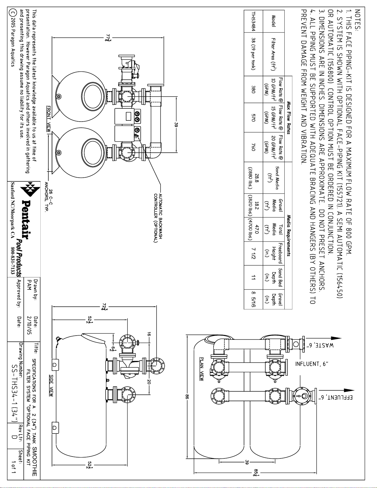
APPENDIX B CONTROLLER INSTALLATION SCHEMATICS
APPENDIX C FILTER SYSTEM SPECIFICATION SHEETS
APPENDIX D VALVE ASSEMBLY DRAWINGS
Diaphragm Valve Face Piping Kit Installation Manual Pg. 37 of 47
1/16/05 Rev. D

Problem Possible Cause Solution
Slow activation of valves
APPENDIX A
1. Faulty or improperly installed check valve
2. Faulty or improperly installed regulator
3. Not enough pressure to the multiport valve
4. Kinked or obstructed controller tubing
5. Failing seals in the multiport valve
Verify that valve was installed correctly, making sure
the arrow points in the proper direction. Refer to
installation instructions for more information. Retry
valve actuation.
Verify that regulator was installed correctly. Refer to
installation instructions for more information. Retry
valve actuation.
Verify that the multiport pressure gauge reads between
35 psi and 40 psi. If not, readjust pressure using
regulator.
Check to see if and controller tubing is kinked or
pinched. If no pinching is present, disconnect the
tubing to the valve not actuating and visually inspect for
debris which may be blocking the tube.
Over time the o-ring seals in the muliport valve can
become worn and brittle. Eventually these seals will
need to be replaced. A good sign of this is water
constantly leaking from the multiport valve drain hose.
A multiport valve rebuild kit is available from the
manufacturer which offers replacement seals.
Inconsistend multiport
valve pressure
Leaking through waste
pipe in normal filtration
mode
Valves not actuating/
Can't intitate backwash
cycle
1. Faulty or improperly installed/adjusted regulator
2. Failing seals in the multiport valve
1. Debris preventing full closure of sideport seal
1. Not enough pressure to the multiport valve
2. Faulty or improperly installed and/or valve
Verify that regulator was installed correctly. Refer to
installation instructions for more information. Adjust
regulator, refer to Section 4.1. If regulator adjustment
does not fix problem, regulator may need to be
replaced.
Over time the o-ring seals in the muliport valve can
become worn and brittle. Eventually these seals will
need to be replaced. A good sign of this is water
constantly leaking from the multiport valve drain hose.
A multiport valve rebuild kit is available from the
manufacturer which offers replacement seals.
Inspect the valve and clear any debris which may be
preventing the side port seal from seating correctly.
Refer to drawing in Appendix for parts reference.
Verify that the multiport pressure gauge reads between
35 psi and 40 psi. If not, readjust pressure using
regulator, refer to Section 4.1.
Verify that the And/Or valve was installed properly.
Refer to installation instructions for more information.
Diaphragm Valve Face Piping Kit Installation Manual Pg. 38 of 47
1/16/05 Rev. D

APPENDIX B
Diaphragm Valve Face Piping Kit Installation Manual Pg. 39 of 47
1/16/05 Rev. D


APPENDIX C


APPENDIX D


 Loading...