

Page 1
HIGH PRESSURE CENTRIFUGAL PUMP FOR
AUTOMATIC SWIMMING POOL CLEANER SYSTEMS
O W N E R’ S M A N U A L
INSTALLATION, OPERATION & PARTS
MODELS
1/2 HP PLBC-178L
Sta-Rite Pool/Spa Group
293 Wright Street, Delavan, WI 53115
International: 262-728-5551, FAX: 262-728-7550
www.starite.com
Union City, TN • Delavan, WI • Mississauga, Ont. • Murrieta, CA
© 2004, Sta-Rite Industries Printed in U.S.A. S44 (Rev. 4/5/04)
This manual should be furnished to
the end user of this pump; its use
will reduce service calls and chance
of injury and will lengthen pump life.
Page 2

2
‘PLB’ SERIES BOOSTER PUMP
To avoid unneeded service calls, prevent possible injuries, and get the most
out of your pump, READ THIS MANUAL CAREFULLY!
The Sta-Rite ‘PLB’ Series Booster pump:
• Is designed for use with automatic swimming pool cleaning systems.
• Is an excellent performer; durable, reliable.
Table of Contents
Safety Instructions ......................................................................................3
Installation...............................................................................................4-5
Electrical.....................................................................................................6
Operation ...................................................................................................7
Storage/Winterizing ....................................................................................7
Pump Service ..........................................................................................8-9
Repair Parts List ........................................................................................10
Troubleshooting Guide .............................................................................11
Warranty...................................................................................................12
Page 3
3
READ AND FOLLOW SAFETY
INSTRUCTIONS!
This is the safety alert symbol. When you see this symbol on your system or in this manual, look for one of the following signal words and
be alert to the potential for personal injury.
warns about hazards that will cause death, serious personal
injury, or major property damage if ignored.
warns about hazards that can cause death, serious personal
injury, or major property damage if ignored.
warns about hazards that will or can cause minor personal
injury or property damage if ignored.
NOTICE indicates special instructions not related to hazards.
Carefully read and follow all safety instructions in this manual and on equipment. Keep safety labels in good condition; replace if missing or damaged.
Incorrectly installed or tested equipment may fail, causing
severe injury or property damage.
Read and follow instructions in owner's manual when installing
and operating equipment. Have a trained pool professional per-
form all pressure tests.
1. Do not connect system to a high pressure or city water system.
2. Use equipment only in a pool or spa installation.
3. Trapped air in system can cause explosion. BE SURE all air is out of system
before operating or testing equipment.
Before pressure testing, make the following safety checks:
Check all clamps, bolts, lids, and system accessories before testing.
Release all air in system before testing.
Tighten Sta-Rite trap lids to 30 ft. lbs. (4.1 kg-m) torque for testing.
Water pressure for test must be less than 25 PSI (7.5 kg/cm
2
).
Water Temperature for test must be less than 100oF. (38oC).
Limit test to 24 hours. After test, visually check system to be sure it is ready
for operation. Remove trap lid and retighten hand tight only.
NOTICE: These parameters apply to Sta-Rite equipment only. For
non-Sta-Rite equipment, consult manufacturer.
Motor normally operates at high temperature and will be too
hot to touch. It is protected from heat damage during operation by an automatic internal cutoff switch. Before handling pump or motor, stop motor and
allow it to cool for 20 minutes.
IMPORTANT
SAFETY
INSTRUCTIONS
Always follow basic safety precautions with this equipment,
including the following.
To reduce the risk
of injury, do not permit children
to use this product unless they
are closely supervised at all
times.
This pump is for use
with permanently installed pools
and may also be used with hot
tubs and spas if so marked. Do
not use with storable pools. A
permanently installed pool is
constructed in or on the ground
or in a building such that it cannot be readily disassembled for
storage. A storable pool is constructed so that it may be readily
disassembled for storage and
reassembled to its original
integrity.
SAVE THESE
INSTRUCTIONS
Page 4
NOTICE: This pump is designed to power automatic swimming pool
cleaners or other systems requiring high pressure at relatively low flow
rates. Operating the pump with open discharge or without flow restriction could overload the pump motor. Operate the pump only while connected to the system in which it is designed to operate. When installed
for automatic time clock operation on a swimming pool cleaner system,
be sure that clock is set so that the cleaner booster pump comes on only
when the main circulation system for the pool is operating. Failure to
coordinate the “on” cycles could provide insufficient flow to the cleaner
booster pump, resulting in failure of the booster pump.
INSTALLATION
Only qualified, licensed personnel should install pump and wiring.
Pump mount must:
Be solid - Level - Rigid - Vibration free. (To reduce vibration and pipe
stress, bolt pump to mount.)
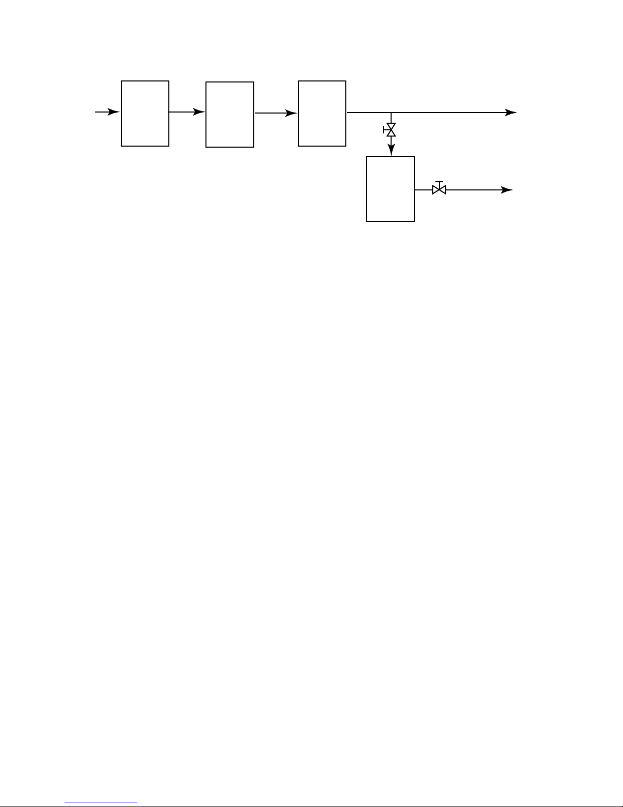
Allow pump suction inlet to be as close to pool return line as possible.
Allow use of short, direct suction pipe from tee on return line (See Fig. 1).
Allow for gate valves in suction and discharge piping.
Have adequate floor drainage to prevent flooding.
Be protected from excess moisture.
Allow adequate access for servicing pump and piping.
NOTICE: Use Teflon tape or Plasto-Joint Stik
1
for making all threaded
connections to the pump. Do not use pipe dope; pipe dope will cause
stress cracking in the pump.
NOTICE: Pump suction and discharge connections have molded in
thread stops. DO NOT try to screw pipe in beyond these stops.
4
From
Pool
Suction
Main
Pool
Pump
Filter
Heater
(If used)
Pool
Booster
Pump
To
Pool
Return
To
Pool
Cleaner
POOL RETURN
GATE
VALVE
3/4" RIGID OR NON-COLLAPSIBLE
FLEXIBLE PLUMBING
FIGURE 1
Page 5

Teflon Taping Instructions:
Use only new or clean PVC pipe fittings.
Wrap male pipe threads with one to two layers of Teflon tape. Cover
entire threaded portion of pipe.
Do not overtighten or tighten past thread stop in pump port!
If leaks occur, remove pipe, clean off old tape, rewrap with one to two
additional layers of tape and remake the connection.
NOTICE: Support all piping connected with pump!
Piping:
Never use a suction pipe smaller than pump suction connection.
Use 3/4” I.D. discharge pipe up to 50’ length. Use 1” pipe if run
is over 50’.
To avoid strains on the pump, support both suction and discharge pipes
independently. Place these supports near the pump.
To avoid a strain left by a gap at the last connection, start all piping at
the pump and run pipe away from the pump.
To avoid airlocking, slope suction pipe slightly upward toward the pump.
NOTICE: To prevent flooding when removing pump for service, all flood-
ed suction systems must have gate valves in suction and discharge pipes.
Fittings:
Fittings restrict flow; for best efficiency use fewest possible fittings.
Avoid fittings which could cause an air trap.
Pool fittings must conform to International Association of Plumbing and
Mechanical Officials (IAPMO) standards.
1
Lake Chemical Co., Chicago, Illinois
5
FIGURE 2
POOL RETURN
LINE
GATE
VALVE
GATE
VALVE
TO POOL CLEANER
3/4" RIGID OR NON-COLLAPSIBLE
FLEXIBLE PLUMBING
PLBC
372 0395
Page 6

ELECTRICAL
Ground motor before connecting to electrical power supply. Failure to
ground motor can cause severe or fatal electrical shock
hazard.
Do not ground to a gas supply line.
To avoid dangerous or fatal electrical shock, turn OFF power to motor
before working on electrical connections.
Ground Fault Circuit Interrupter (GFCI) tripping indicates an electrical
problem. If GFCI trips and will not reset, have a qualified
electrician inspect and repair electrical system.
Exactly match supply voltage to nameplate voltage! Incorrect voltage
can cause fire or seriously damage motor and voids warranty.
If in doubt consult a licensed electrician.
Voltage:
Voltage at motor must be not more than 10% above or below motor nameplate
rated voltage or motor may overheat, causing overload tripping and reduced
component life. If voltage is less than 90% or more than 110% of rated voltage
when motor is running at full load, consult power company.
Grounding/Bonding:
Install, ground, bond and wire motor according to local or National Electrical
Code requirements.
Permanently ground motor. Use green ground terminal provided under motor
canopy or access plate (See Figure 3A); use size and type wire required by
code. Connect motor ground terminal to electrical service ground.
Connect a No. 8 AWG (8.4 sq. mm) solid copper bonding wire to the pressure
wire connector provided on the motor housing and to all metal parts of the
swimming pool, spa, or hot tub and to all electrical equipment, metal piping or
conduit within 5 feet (1.5m) of the inside walls of swimming pool, spa, or hot
tub.
Wiring (See Figure 3B):
Pump must be permanently connected to circuit. Table I, Page 6, gives correct
wire and circuit breaker sizes for the pump alone. If other lights or appliances
are also on the same circuit, be sure to add their amp loads to pump amp load
before figuring wire and circuit breaker sizes. (If unsure how to do this or if this
is confusing, consult a licensed electrician.) Use the load circuit breaker as the
master on-off switch.
Install a Ground Fault Circuit Interrupter (GFCI) in circuit; it will sense a shortcircuit to ground and disconnect power before it becomes dangerous to pool
users. For size of GFCI required and test procedures for GFCI, see manufacturer’s instruction.
In case of power outage, check GFCI for tripping (which will prevent normal
pump operation). Reset if necessary.
NOTICE: If you do not use conduit when wiring motor, be sure to seal wire
opening on end of motor to prevent dirt, bugs, etc., from entering.
6
Hazardous voltage.
Can shock, burn,
or cause death.
Ground pump before
connecting to
power supply.
FIGURE 3A: Typical ground screw
and bonding lug locations
FIGURE 3B: Wiring connection
diagram
TABLE I - RECOMMENDED FUSING AND WIRING DATA
Dist. in Ft. (m) (Serv. to Motor)
Motor Branch Fuse Max Load Voltage/ 0-100’ 101-200’ 201-300’
H.P. Rating Amps* Amps Hz/Phase (0-30) (31-60) (61-90)
1/2 20 13.4 115/60/1 12 (3) 10 (5.5) 8 (8.4)
1/2 15 6.7 230/60/1 14 (2) 14 (2) 14 (2)
*Time delay fuses are recommended instead of standard fuses in any motor circuit.
BONDING
LUG
GREEN
GROUND
SCREW
Motor Terminal Board Connections
SINGLE
VOLTAGE
MOTORS
Blue
L2
B
A
L1
White
230
Volt
Lines
VOLTAGE
MOTORS
White
w/Black
Tracer
Black
White
w/Black
Tracer
Black
DUAL
B
B
L2
115
Volt
Lines
A
L1
L2
230
Volt
Lines
A
L1
Page 7

OPERATION
NEVER run pump dry! Running pump dry may damage seals, causing
leakage and flooding! Fill pump with water before starting
motor.
Before working on pump:
1. STOP PUMP before proceeding.
2. CLOSE GATE VALVES in suction and discharge pipes.
3. RELEASE ALL PRESSURE from pump and piping system.
4. NEVER tighten or loosen clamp while pump is operating!
Priming Pump:
Release all air from filter and piping system: see filter owner’s manual.
Pump will prime itself when suction and discharge valves are opened, and
main pool pump is running.
If pump does not prime, make sure that all valves are open, main pool pump
is running, and that there are no leaks in suction pipe. See Troubleshooting
Guide, Page 11.
Storage/Winterizing:
NOTICE: Allowing pump to freeze will damage pump and void warranty!
NOTICE: Do not use anti-freeze solutions (except propylene glycol) in your
pool/spa system. Propylene glycol is non-toxic and will not damage plastic
system components; other anti-freezes are highly toxic and may damage
plastic components in the system.
Drain all water from pump and piping when expecting freezing temperatures
or when storing pump for a long time (see instructions, Page 7).
Keep motor dry and covered during storage.
To avoid condensation/corrosion problems, do not cover pump with plastic.
For outdoor/unprotected installations:
1. Enclose entire system in a weatherproof enclosure.
2. To avoid condensation/corrosion damage, allow ventilation; do not
wrap system in plastic.
3. Use a 40% propylene glycol/60% water solution to protect pump
to - 50°F.
Draining Pump:
1. Pump down water level below all inlets to the pool.
To avoid dangerous or fatal electrical shock hazard, turn OFF power
to motor before draining pump.
2. Use low pressure air to blow accumulated water from the piping system.
3. To prevent pump from freezing, remove priming plug and drain the pump
body through the drain plug (Key No. 18, Page 10). Clean pump thoroughly; replace priming plug.
4. Be sure motor is kept dry and covered.
Startup For Winterized Equipment:
1. Remove any temporary weather protection placed around system for shutdown.
2. Follow filter manufacturer’s instructions for reactivation of the filter.
3. Inspect all electrical wiring for damage or deterioration over the shutdown
period. Have a qualified serviceman repair wiring as needed.
4. Inspect and tighten all watertight connections.
5. Open all valves in suction and return piping.
6. Remove any winterizing plugs in piping system.
7. Drain all antifreeze from system.
8. Close all drain valves and replace all drain plugs in piping system.
9. Prime pump according to instructions above.
7
Hazardous voltage.
Can shock, burn,
or cause death.
Disconnect power
before working
on pump or motor.
Page 8

8
PUMP SERVICE
Pump should only be serviced by qualified personnel.
Be sure to prime pump (Page 7) and start main pool pump before starting.
Before removing trap cover:
1. STOP PUMP before proceeding.
2. CLOSE GATE VALVES in suction and discharge pipes.
3. RELEASE ALL PRESSURE from pump and piping system.
4. NEVER tighten or loosen clamp while pump is operating!
To avoid dangerous or fatal electrical shock hazard, turn OFF power
to motor before working on pump or motor.
Aside from lubricating trap cover O-Ring, no lubrication or regular maintenance is needed beyond reasonable care and periodic cleaning.
If shaft seal is worn or damaged, repair as follows:
Pump Disassembly/Removing Old Seal:
Disconnect power to pump motor.
Be sure gate valves on suction and return piping are closed before starting
work.
Release all pressure before starting work.
1. Drain pump by removing drain plugs on bottom of pump body and trap
body.
2. Remove clamp holding pump halves together (Figure 4).
3. Remove pump base mounting bolts. Motor and seal plate assembly can
now be pulled away from pump body.
4. Remove five screws and washers holding diffuser to seal plate. Remove
diffuser (Figure 5).
5. If impeller must be replaced, loosen two machine screws and remove
motor canopy (see Figure 6).
6. Capacitor voltage may be hazardous. To discharge capaci-
tor, hold insulated handle screwdriver BY THE HANDLE and short capacitor terminals together (see Figure 6). Do not touch metal screwdriver
blade or capacitor terminals. If in doubt, consult a qualified electrician.
7. Unscrew capacitor clamp and remove capacitor. Do not disconnect
capacitor wires to motor.
8. Slide 7/16” open end wrench in behind spring loaded switch on motor
end of shaft; hold motor shaft with wrench on shaft flats and unscrew
impeller by turning counterclockwise when looking into eye of impeller.
9. Unscrew four nuts holding pump back half to motor. Remove rotating half
of seal by placing two screwdrivers under back half of pump body and
carefully prying up (Figure 7, Page 9). Back half of pump body will slide
off shaft, bringing seal with it.
NOTICE: Be sure you do not scratch or mar shaft; if shaft is marred, it
must be dressed smooth with fine emery or crocus cloth before installing
new seal. DO NOT reduce shaft diameter!
10. Place pump body face down on flat surface and tap out stationary half of
seal (see Figure 8, Page 9).
FIGURE 4
FIGURE 5
FIGURE 6
To avoid electrical
shock hazard, use
insulated-handle
screwdriver to short
capacitor terminals
as shown.
1193 0794
Page 9

Installing New Seal/Pump Reassembly:
1. Clean seal cavity in seal plate.
2. Wet outer edge of O-Ring on ceramic seat with liquid soap. Be sparing!
3. Put cardboard washer over seal face. With thumb pressure, press ceramic seal half firmly and squarely into seal cavity in seal plate (see Fig. 9).
Polished face of ceramic seat is up. If seal will not seat correctly,
remove, placing seal face up on bench. Reclean cavity. Seal should now
seat correctly.
4. If seal does not seat correctly after recleaning cavity, place a cardboard
washer over polished seal face and carefully press into place using
piece of standard 3/4” pipe as a press.
NOTICE: Be sure you do not scratch seal face.
5. Dispose of cardboard washer and recheck seal face to be sure it is free
of dirt, foreign particles, scratches and grease.
6. Inspect shaft to be sure it is free of nicks and scratches.
7. Reassemble pump body half to motor flange. BE SURE it is right side up.
8. Apply liquid soap sparingly (one drop is sufficient) to inside diameter of
rotating seal member.
9. Slide rotating seal member (carbon face first) onto shaft until rubber
drive ring hits shaft shoulder.
NOTICE: Be sure not to nick or scratch carbon face of seal when pass-
ing it over threaded shaft end or shaft shoulder. The carbon surface must
remain clean or short seal life will result.
10. Hold motor shaft with 7/16” open end wrench on shaft flats and screw
impeller onto shaft. Tightening impeller will automatically locate seal in
correct position.
11. Remount diffuser on pump body half with five screws.
Pump Reassembly:
1. Clean O-Ring and O-Ring groove.
2. Put O-Ring in groove on face of seal plate; put pump halves together
(see Figure 10).
3. BE SURE inside of clamp is clean. Place clamp on pump halves; snug up.
Alternately tighten screw and tap clamp with mallet to seat O-Ring (see
Figure 11).
4. Replace base mounting bolts.
5. Replace drain plug.
6. Prime pump according to instructions. See “Operation”, Page 7.
7. Check for leaks.
9
FIGURE 7
FIGURE 8
FIGURE 9
479 0194
477 0194
FIGURE 10
FIGURE 11
P
609 0395
Page 10

10
21
EXPLODED VIEW
Key Part No.
No. Description Used PLBC-178L
1 Motor 1/2 H.P. - 115/230V - 60 Cycle 1 A100CHL
1A Lug - Bonding 1 U17-568
1B Screw - #10 - 32 x 1/2” Lg. 1 U30-692SS
2 Water Slinger 1 C69-2
3 Pipe Plug - 1/2” 1 WC78-39T
4 Tank Body - Back Half 1 L176-47P
5 O-Ring 1 U9-389
6 Shaft Seal 1 17351-0102S
7Impeller 1 J105-8PACN
8 Diffuser 1 J1-40P
9 Screw - #8 - 32 x 7/8” Lg. 5 U30-542SS
10 O-Ring - Diffuser 1 U9-199
11 Clamp - Tank Body 1 C19-54SS
12 Reducer Bushing 1 U78-118PT
13 Tank Body - Front Half 1 L76-37P
14 Pipe Plug - 1/8” 1 WC78-41T
15 Bushing 1 L23-4P1
15A Gasket 1 L20-40
16 Reducer Bushing - 1-1/4” x 3/4” 1 U78-123PT
17 Pipe Plug - 1” 1 U78-830PT
18 Pipe Plug - 1/4” 2 WC78-40T
19 Base 1 C4-42P
20 Washer - Lock 4 U43-11SS
21 Nut - Hex - 5/16” - 18 4 U36-37SS
22 Motor Pad 1 C35-11
• Tag, “Caution. Use with permanent. . .” 1 61002-0002
REPAIR PARTS LIST
• Not illustrated.
20
22
1
1B
1A
2
19
3
4
5
6
7
8
9
10
11
18
18
367 0395
12
13
14
15A
15
16
17
Page 11

TROUBLESHOOTING GUIDE
Read and understand safety and operating instructions in this manual
before doing any work on pump!
Only qualified personnel should electrically test pump motor!
FAILURE TO PUMP; REDUCED CAPACITY OR DISCHARGE PRESSURE
Suction leaks/lost prime:
1. Pump must be primed; make sure that main pool pump is running.
See priming instructions, Page 7.
2. Make sure there are no leaks in suction piping.
Clogged pipe/trap/impeller, worn impeller:
1. Make sure impeller is not clogged (follow steps 1 through 7 under
“Removing Old Seal”, Page 8; check impeller for clogging; follow steps
7 through 11 under “Installing New Seal”, Page 9, for reassembly).
2. Impeller and diffuser may be worn. If so, order replacement parts from
Repair Parts List, Page 10.
Electrical:
1. Pump may be running too slowly; check voltage at motor terminals and
at meter while pump is running. If low, see wiring instructions or consult
power company. Check for loose connections.
2. Pump may be too hot.
A. Check line voltage; if less than 90% or more than 110% of rated
voltage consult a licensed electrician.
B. Increase ventilation.
Mechanical Troubles and Noise:
1. If suction and discharge piping are not adequately supported, pump
assembly will be strained. See “Installation”, Page 4.
2. Do not mount pump on a wooden platform! Securely mount on concrete platform for quietest performance.
11
Hazardous voltage.
Can shock, burn,
or cause death.
Disconnect power
before working
on pump or motor.
Page 12

▲ Retain Warranty Certificate (upper portion) in a safe and convenient location for your records.
DETACH HERE: Fill out bottom portion completely and mail within 10 days of purchase/installation to:
▼ Sta-Rite, Attn: Warranty Dept., 293 Wright St., Delavan, WI 53115
Pumps, filters, skimmers, underwater lights (except bulbs),
accessories and fittings manufactured by Sta-Rite are warranted to be free of defects in material and workmanship
for one (1) year from date of installation.
Product specific warranties:
Year from date
of installation
HRPB, DEPB and System 3 – Tanks . . . . . . . . . .10 years
Internal filter components and valves . . . . . . . . 1 year
Max-E-Therm – Pool/Spa Heaters . . . . . . . . . . . . 2 years
Heater Enclosure only (Upper RH & LH;
lower enclosure; and control board enclosure)…10 years
Automatic Pool Cleaners including Hose . . . . . . 2 years
Cristal-Flo filters – Tanks . . . . . . . . . .10 years pro-rated*
Valve and internal components. . . . . . . . . . . . . . 1 year
Posi-Flo II – Tanks . . . . . . . . . . . . . . . . . . . . . . . .10 years
Elements . . . . . . . . . . . . . . . . . . . . . . . . . . . . . . 1 year
PRC Cartridge –
Filter Tanks . . . . . . . .5 years pro-rated (1st 2 years full)
Elements . . . . . . . . . . . . . . . . . . . . . . . . . . . . . . 1 year
System 3 Above Ground Systems – Tanks . . . . . .10 years
Pumps / Platform and Internals . . . . . . . . . . . . . 1 year
Pumps . . . . . . . . . . . . . . . . . . . . . . . . . . . . . . . . . . 1 year
When equipped with A.O. Smith
2-compartment motors (Does not include
pumps sold as part of a systems package) . . . . . 2 years
Traps / In-Line Strainers . . . . . . . . . . . . . . . . . . . 1 year
Vertical Commercial Filter – Tanks . . . . . . . . . .10 years
Internals . . . . . . . . . . . . . . . . . . . . . . . . . . . . . . . 1 year
Horizontal Commercial Filter
Tanks . . . . . . . . . . . . . . . . . . . . . . . . . . . . . . . . .5 years
(Years 6-9, Prorated declining 20%/year, Yr. 10 - 10%)
Internals . . . . . . . . . . . . . . . . . . . . . . . . . . . . . . . 1 year
* Full warranty coverage is in effect for one year after installation. The pro-rated warranty covers the tank only during
the 2nd through 10th year after installation. The amount
covered decreases by 10% each year. (ie., 2nd year 90% covered, 3rd year 80% covered, etc.).
The foregoing warranties relate to the original consumer
purchaser (“Purchaser”) only. Sta-Rite shall have the option
to repair or replace the defective product, at its sole discrtion. Purchasers must pay all labor and shipping charges
necessary to replace the product covered by this warranty.
Requests for warranty service must be made through the
installing dealer. This warranty shall not apply to any product that has been subject to negligence, misapplication,
improper installation or maintenance, or other circumstances which are not in Sta-Rite’s direct control.
This warranty sets forth Sta-Rite’s sole obligation and
Purchaser’s exclusive remedy for defective products.
STA-RITE SHALL NOT BE LIABLE FOR ANY CONSEQUENTIAL, INCIDENTAL OR CONTINGENT DAMAGES WHATSOEVER.
THE FOREGOING WARRANTIES ARE EXCLUSIVE AND IN
LIEU OF ALL OTHER EXPRESS WARRANTIES. IMPLIED
WARRANTIES, INCLUDING BUT NOT LIMITED TO THE
IMPLIED WARRANTIES OF MERCHANTABILITY AND FITNESS FOR A PARTICULAR PURPOSE, SHALL NOT EXTEND
BEYOND THE DURATION OF THE APPLICABLE EXPRESS
WARRANTIES PROVIDED HEREIN.
Some states do not allow the exclusion or limitation of incidental or consequential damages or limitations on how long
an implied warranty lasts, so the above limitations or exclusion may not apply to you. This warranty gives you specific
legal rights and you may also have other rights which vary
from state to state.
Supersedes all previous publications.
Sta-Rite Industries
293 Wright St., Delavan, WI 53115
Warranty Registration Card
Name
Address
City State Zip
Purchase Date
Product Purchased
■■ New installation ■■ Replacement
Type of Pool ■■ Inground ■■ Vinyl ■■ Fiberglass ■■ Gunite
Size of Pool
Years pool has been in service ■■ less than 1 ■■ 1-3 ■■ 3-5 ■■ 5-10
Purchased from:
Company name
Address
City State Zip
Please send me more information on these
other products from Sta-Rite.
■■ Pumps ■■ Filters ■■ Automatic Pool Cleaners
■■ Maintenance Equipment ■■ Test Strips
■■ Heaters
S4877PS (Rev. 5/15/00)
STA-RITE LIMITED WARRANTY
 Loading...