

Page 1
OWNER’S MANUAL
PENTEK INTELLIDRIVE
™
293 Wright Street, Delavan, WI 53115
Phone: 866-9 PENTEK (866-973-6835)
Fax: 800-426-9446
www.pumps.com
PID10, PID20, PID50
Installation/Operation/Parts
For further operating, installation,
or maintenance assistance call:
©2012 PN957 (08/14/12)
866-9PENTEK
(866-973-6835)
Page 2

Safety 2
Important Safety
Instructions
SAVE THESE INSTRUCTIONS - This manual
contains important instructions that should be
followed during installation, operation, and
maintenance of the PENTEK INTELLIDRIVE Variable
Frequency Drive (VFD).
This is the safety alert symbol. When you see
this symbol on your PENTEK INTELLIDRIVE or in
this manual, look for one of the following signal
words and be alert to the potential for personal
injury!
avoided, will result in death or serious injury.
avoided, could result in death or serious injury.
avoided, could result in minor or moderate injury.
NOTICE addresses practices not related to
personalinjury.
Carefully read and follow all safety instructions in
this manual and on the PENTEK INTELLIDRIVE.
Keep safety labels in good condition. Replace
missing or damaged safety labels.
from EMI/RFI filter inside drive. Can shock,
burn or kill if the front cover of the PENTEK
INTELLIDRIVE is open or removed while power
is connected to the Drive or the Drive is running.
The front cover of the Drive must be closed during
operation.
• Makeallwiringconnections,thencloseand
• NEVER open the box when power is connected to
• Beforedoinganyserviceormaintenanceinside
• Beforestartinganywiringorinspection
• NEVER connect power wiring to
• NEVER handle or service
• NEVER reach into or change the cooling fan while
• NEVER touch the printed circuit board when
indicates a hazard which, if not
indicates a hazard which, if not
indicates a hazard which, if not
Risk of high-voltage electrical shock
fasten the cover before turning on power to drive.
Drive.
Drive or when connecting or disconnecting any
wires inside Drive:
1. DISCONNECT power.
2. WAIT 5 minutes for retained voltage
todischarge.
3. Open box.
procedures, check for residual voltage with a
voltage tester.
Drive
mounting the box.
hands. Always make sure hands are dry before
working on
power is applied to Drive.
power is applied to Drive.
Drive
Drive
.
before
with wet or damp
property damage or death if installed with incorrect
or inadequate circuit breaker protection. To ensure
protection in the event of an internal fault in the
PENTEK INTELLIDRIVE, install the Drive on an
independent branch circuit protected by a circuit
breaker (see Table 2 for circuit-breaker sizing), with
no other appliances on the circuit.
hot during normal operation. Allow it to cool for
5minutes after shut-down and before handling it to
avoid burns.
NOTICE To avoid damage to Drive or problems
with Drive:
• Connectoutputcablesto3-wire and 3-phase
RedtoR,YellowtoY,BlacktoB.
Any other order will reverse the motor rotation
• Connectoutputcablesto2-wire 1-phase
ConnecttoYandBonly.
Connect Ground to green screw.
• Aboveground3-phasemotorsmayhavedifferent
RtoL1,YtoL2,BtoL3.
Verify rotation after startup.
• Donotmodifyequipment.
• Donotusepowerfactorcorrectioncapacitors
• Donotremoveanypartsunlessinstructedtodo
• DonotuseamagneticcontactoronDrivefor
• DonotinstalloroperateDriveifitisdamagedor
• BeforestartingDrivethathasbeeninstorage,
• Donotcarryoutamegger(insulationresistance)
• Donotallowlooseforeignobjectswhichcan
• GroundDriveaccordingtotherequirementsof
• Allinstallation,servicework,andinspections
Risk of fire. Can cause severe injury,
Risk of burns. The Drive can become
submersible motors as follows:
and may damage the motor.
submersible motors as follows:
lead colors. Generally connect output leads
asfollows:
Drive
PENTEK
.
as they will damage both motor and
INTELLIDRIVE
so in Owner’s Manual.
frequent starting/stopping.
parts are missing.
always inspect it and test operation.
test on the control circuit of the
conduct electricity (such as screws and metal
fragments) inside Drive box at any time. Do not
allow flammable substances (such as oil) inside
Drive box at any time.
the National Electrical Code Section 250, IEC536
Class 1, or the Canadian Electrical Code (as
applicable) , and any other codes and ordinances
that apply.
must be done by qualified electrician.
.
Page 3
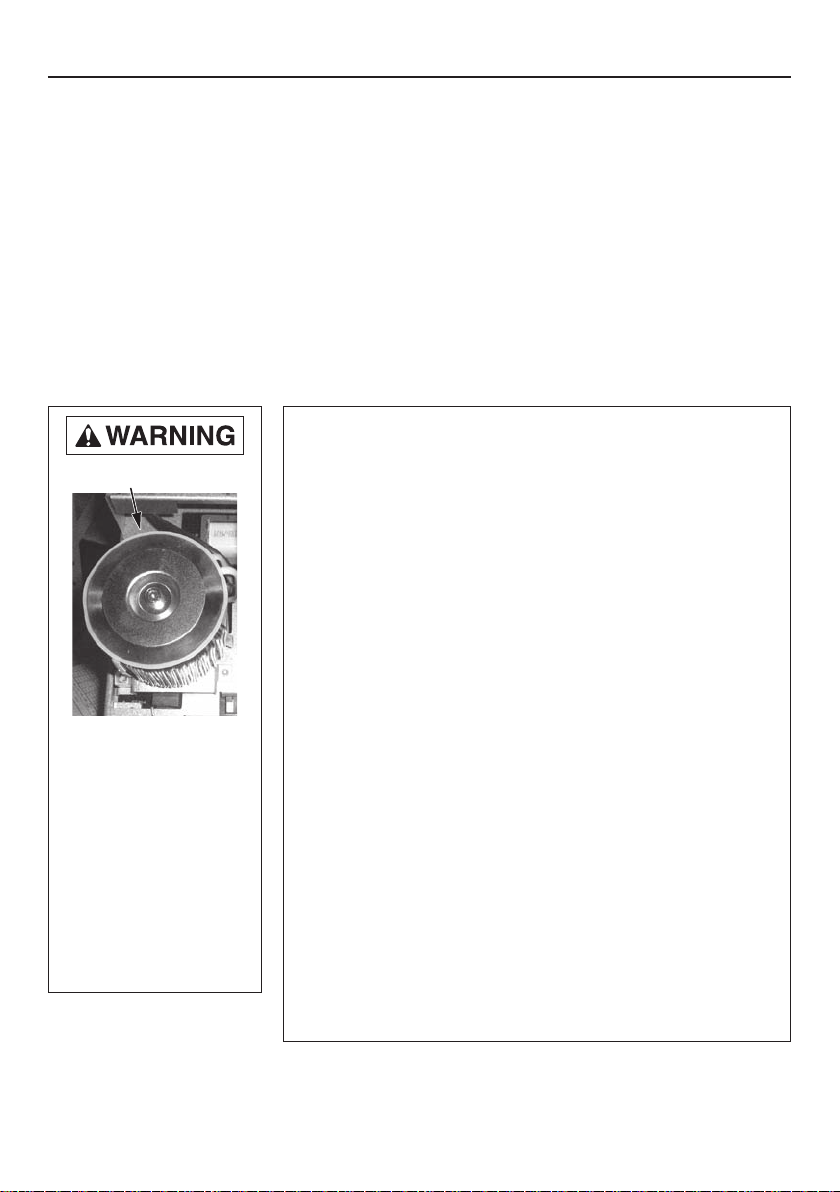
Table of Contents 3
Safety .............................................................2
Owner’s Information .................................................3
Description ...................................................... 4-5
Installation ...................................................... 6-10
In itial Startup ................................................... 11-12
Programming ................................................... 13-16
I/O Connections ................................................ 17-18
Additional Information ..............................................19
Troubleshooting ................................................ 20-22
Warranty .........................................................23
Owner’s Information
PENTEK INTELLIDRIVE Model No. _________________________
EMI/RFI Filter
PENTEK INTELLIDRIVE Serial No. _________________________
Pump Model No. _________________________
Pump Serial No. _________________________
Motor Model No. _________________________
Motor Service Factor Amps _________________________
Risk of electric shock. Can
shock, burn or kill.
• Drive’sinternal
components retain
high voltage for up to
5minutes after input
power is disconnected.
• EMI/RFIFiltercarries
high voltage when pump
is running.
• Disconnectpowerand
wait 5 minutes before
opening
PENTEK
INTELLIDRIVE
cover.
Pressure Tank Model No. _________________________
Pressure Tank Serial No. _________________________
Dealer/Installer: _____________________________________________
_____________________________________________
Installer Phone No. _________________________
Date of Installation _________________________
Wire Lengths in Feet (Meters):
CircuitBreakertoDrive _________________________
PENTEK INTELLIDRIVE to Motor _________________________
Supply Voltage _________________________
Note to Installer: Record the data listed above for future reference. Give manual to
end user or attach to
PENTEK INTELLIDRIVE
when installation is complete.
Page 4
Description 4
Specifications/Ratings
Input Voltage ........... 1-Phase 230VAC Nominal (190–265VAC)
Input Frequency .........................................................50/60Hz
Ambient Tempature Range ............ -4 to 122 °F (-20° to 50 °C)
Output Connections ..................3-Phase, 3-Wire/1-Phase or
Max Motor Cable Length .......................................... 1,000 feet
Enclosure ....................................................................... Type 1
Table 1 - Specifications
Model
PID10 1.0
PID20 2.0 13.5
Max HPInput
Phase
1
Operation
2-wire, 3-wire,
PID50 5.0 1 3-phase 18.0
The PENTEK INTELLIDRIVE is specifically designed
to operate 4” submersible pumps and 3-phase
above ground pumps in water well and residential
booster applications. Each Drive is rated for
maximum output amp rating. Any use of Drive
outside of intended design parameters will void
warranty. If Drive is used with above ground motors
not rated for a Variable Frequency Drive, maximize
motor life by limiting lead length to 25 ft. Refer to
pump Owner’s Manual and the National Electrical
Code for proper wire size.
Motor
3-phase
1-Phase/2-Wire
Max
Amps
10.5
Each carton contains:
• PENTEK INTELLIDRIVE Variable Frequency Drive
•PressureTransducer
•10’PressureTransducerCable
•QuickStartGuide
•Owner’sManual
PENTEK INTELLIDRIVE Model Number Structure
PIDXX
Product Family
PID - PENTEK INTELLIDRIVE
HP Range
10 = up to 1.0 HP
20 = up to 2.0 HP
50 = up to 5.0 HP
The PID10 and PID20
will operate a 1-phase
2-wire, 1-phase 3-wire, and 3-phase motor up to the
HP range of the Drive. The
PID50 only operates a
3-phase motor up to 5 HP.
Gnd
(3 phase only)
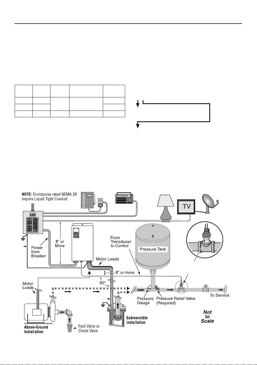
Figure 1 -
PENTEK
INTELLIDRIVE™
Gnd
A typical residential installation layout
Transducer; install in straight
pipe downstream of tank, at
least one foot away from
pipe fittings on each side.
Page 5
Description 5
Transducer
The PENTEK INTELLIDRIVE uses a 4-20mA,
0-100PSI pressure transducer to control motor
speed (max is 300 PSI transducer).
The transducer (see Figure 1) senses pressure in
the pipe and converts it to an electrical signal.
The Drive senses and processes the signal in the
PID (Proportional, Integration, Derivative) control.
When operating in AUTOSTART mode, the Drive
increases and decreases the speed of the pump
motor as needed to maintain constant pressure in
the piping system.
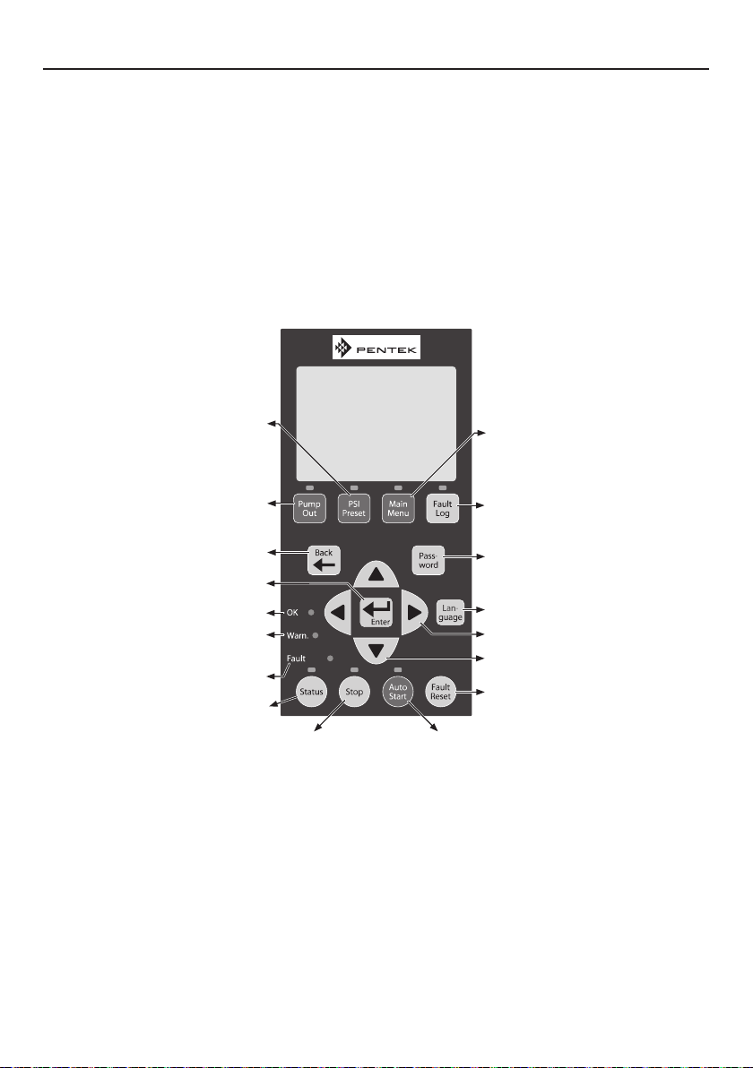
Changes internal pressure setpoint from
15 PSI to transducer max -3PSI
Runs the Drive at 45Hz (with no
pressure control) to allow installer to
Changes display to previous screen.
Selects menu items and confirms
Drive is in Warning Mode (TPM); refer to
Displays Drive’s current operating
condition and changes display
Figure 2 - PENTEK INTELLIDRIVE keypad functions
(default is 60 PSI).
pump out well.*
numeric value changes.
Power is ON to Drive.
Troubleshooting section.
A fault has occurred.
parameters.
Stops the motor.
Keypad
The keypad programs the Drive, monitors the status
of the pump, and displays faults if they occur.
Each button has a unique function, as described in
Figure 2. The LCD display shows a text display of
the status of the Drive’s operation. Other LEDs light
up to indicate when certain buttons are pressed or
certain events occur.
Fan
The Drive uses a thermostatically controlled
internal fan which operates automatically when
necessary to cool the Drive components.
Views and changes parameters.
Shows last 15 faults.
With code, locks and unlocks password
protected keys.
Toggles between English, Spanish, and
French (default is English).
Left and right arrows move cursor.
Up and down arrows scroll through
menus and change numeric values.
Resets fault that stopped Drive/pump.
Checks for line fill, then starts pump in
constant pressure mode.
Page 6

Installation 6
Table 2 - Circuit Breaker and Wire Sizes.
Motor
2-wire
3-wire
3 phase
* AWG will change depending on the length of wire. See Tables 3-6.
** With properly-sized circuit breakers, the Drive is protected from short circuit on the input and the
output. There is no risk of fire or electrical shock due to a short circuit. The Drive has NEC Class 10
overload protection.
*** Minimum 240V generator size.
NOTICE Information in Tables 3-6 applies ONLY to PENTEK® motors. For other motors, refer to motor
manufacturer specifications for wire sizing.
Drive
Model
PID10
PID20 1-1/2 10 10 25 5.3
PID10
PID20
PID10
PID20
PID50
Volts Motor HP
1/2 14 14
3/4
1 20 4.4
1/2 14 14
3/4
1 3.5
230
1-1/2
2 5.8
1/2
3/4 2.8
1
1-1/2
2
3 10 30 7.3
5 6 8 50 12.6
Wire Size*
Input Output
12 12
12 12
10 10 25
14
12
10
Circuit Breaker** Generator (kVA)***
14 15
12
15
15
20 4.4
25 5.5
2.2
3.1
2.3
3.0
5.3
2.1
3.4
Table 3 - Service Entrance to Drive - 1 Phase, 2-Wire 40°C Ambient, and 5 percent Voltage Drop,
60C and 75C Insulation (copper only).
Motor Rating Maximum Cable Length in feet (M)
Volts HP SFA 14 AWG 12 AWG 10 AWG 8 AWG 6 AWG 4AWG
1/2 4.7 447 (136) 712 (217) 1000 (305) –
3/4 6.2 341(104) 542 (165) 864 (263) 1000 (305)
1 8.1 261(79) 415 (126) 661 (202) 1000 (305)
230
1 1/2 10.4 203 (62) 323 (98) 515 (157) 816 (249) 1000 (305)
2 12.2 173 (53) 275 (84) 439 (134) 696 (212) 1000 (305)
3 10.1 209 (64) 333 (101) 530 (162) 840 (256) 1000 (305)
5 17.5 121(37) 192 (59) 306 (93) 485 (148) 754 (230) 1000 (305)
–
–
Page 7

Installation 7
Table 4 - AWG Wire Sizing, Drive to 1-Phase, 2-Wire Motor, 40°C Ambient, and 5 percent Voltage Drop,
60C and 75C Insulation (copper only).
Motor P/N
P42B0005A2-01
P42B0010A2-01 1 8.1 261 (80) 415 (126) 661 (201) 1000 (305)
Motor Rating Maximum Cable Length in feet (M)
Volts HP SFA 14 AWG 12 AWG 10 AWG 8 AWG 6 AWG
1/2 4.7 447 (136) 712 217) 1000 (305) –
230
–P42B0007A2-01 3/4 6.2 341 (104) 542 (165) 864 (263) 1000 (305)
P42B0015A2-01 1 1/2 10.4 203 (62) 323 (98) 515 (157) 816 (249) 1000 (305)
Table 5 - AWG Wire Sizing, Drive to 3-Wire, 1-Phase Motor, 40°C Ambient, and 5 percent Voltage Drop,
60C and 75C Insulation (copper only).
Motor P/N
P43B0005A2-01
Motor Rating Maximum Cable Length in feet (M)
Volts HP SFA 14 AWG 12 AWG 10 AWG 8 AWG 6 AWG
1/2 4.8 440 (134) 700 (213) 1000 (305) –
–P43B0007A2-01 3/4 6 352 (107) 560 (171) 893 (272) 1000 (305)
P43B0010A2-01 1 7.3 289 (88) 460 (140) 734 (224) 1000 (305)
230
P43B0015A2-01 1 1/2 10.9 194 (59) 308 (94) 492 (150) 778 (237) 1000 (305)
P43B0020A2-01 2 12.2 173 (53) 275 (84) 439 (134) 696 (212) 1000 (305)
Table 6 - AWG Wire Sizing, Drive to 3-Phase Motor, 40°C Ambient, and 5 percent Voltage Drop,
60C and 75C Insulation (copper only).
Motor P/N
P43B0005A3
P43B0007A3 3/4 3.9 541 (165) 861 (262) 1000 (305)
P43B0010A3 1 4.7 449 (137) 715 (218) 1000 (305)
P43B0015A3 1 1/2 6.1 346 (105) 551 (168) 878 (268) 1000 (305)
P43B0020A3 2 7.6 278 (85) 442 (135) 705 (215) 1000 (305)
P43B0030A3 3 10.1 209 64) 333 (101) 530 (162) 840 (256) 1000 (305)
P43B0050A3 5 17.5 306 (93) 485 (148) 754 (230) 1000 (305)
Motor Rating Maximum Cable Length in feet (M)
Volts HP SFA 14 AWG 12 AWG 10 AWG 8 AWG 6 AWG 4 AWG*
1/2 2.9 728 (222) 1000 (305) –
–
_
230
_
*Installations that require wire gauge larger than 6AWG will require an external junction box. Run 6AWG
wire from the Drive into the junction box, then make external connections with wire nuts to appropriately
sized wire.
Page 8
8Installation 8
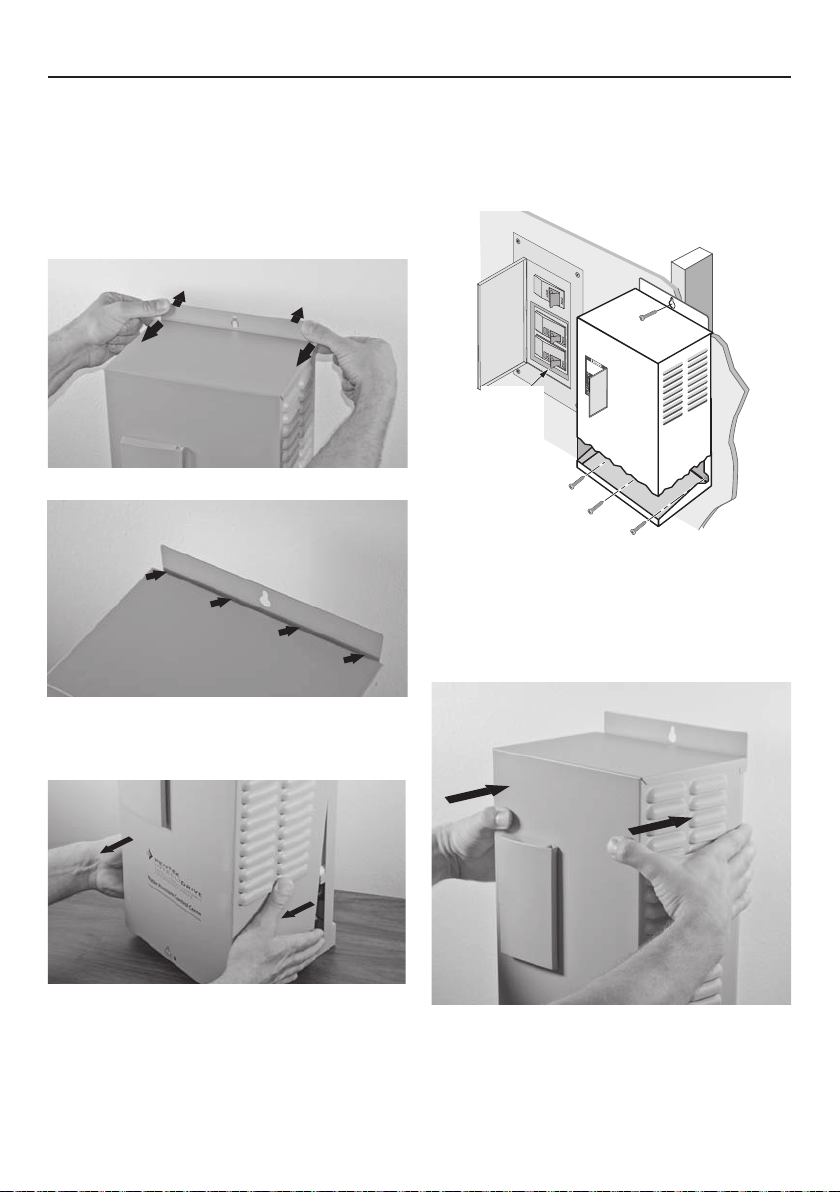
Mounting the Drive
To mount the Drive as shown in Figure 6, follow
this procedure:
1. First, remove the cover by backing out screw
at bottom of front cover.
2. Push on backplate with thumbs while pulling
the cover toward you with index fingers,
creating a gap. See Figures 3 and 4.
Figure 3 - Seperate cover and backplate
Gap
5. Ensure the Drive’s ventilation holes are not
blocked and there is enough space around it
to allow free air flow (minimum 3” clearance
on top, bottom, and sides). See Figure 6. Once
the Drive is mounted, electrical wiring can be
connected.
Typical
230VAC
Circuit
Breaker
(Double
Width)
Figure 6 - Attaching Drive to wall
6. To reattach the Drive cover, hook the top of it
on backplate (be sure to leave a gap). Lower
bottom of cover into place. Push cover evenly
against backplate, eliminating the gap. See
Figure 7.
Figure 4 - Gap between cover and backplate
3. Pull bottom of cover towards you; liftup on
cover and remove. See Figure 5.
Figure 5 - Pull out bottom of cover
4. With the cover removed, permanently mount
the Drive using the top slotted hole, plus
either the three bottom holes (for flat surface
mounting) or the center bottom hole (for
attaching to a post or stud). See Figure 6.
Figure 7 - Reattaching Drive cover
7. Replace screw at bottom of front cover.
Page 9

9Installation 9
Wiring
To allow for ease of wiring, the enclosure wiring
area is free of electronics other than the terminals.
Conduit holes and knockouts are located so
that the wire can be fed straight through to the
connectors, with minimal bending. The terminals
accept 6-14 AWG wire.
Installations that require larger wire gauge than
6AWG will require an external junction box. Run
6AWG wire from the Drive into the junction box,
then make external connections with wire nuts to
appropriately sized wire.
NOTICE For convenience in wiring, the input and
motor terminals unplug from the box. Pull them
down to remove them for ease of access, as shown
in Figure 9.
Verify that the terminal connectors are completely
seated when you replace them. It is best practice
Figure 8 - Pull input and motor terminals down to
remove, making wiring easier.
to connect all output wires (larger wire gauge) first,
then all input wires.
Pump Connections
If the PENTEK INTELLIDRIVE is used with above
ground motors not rated for Variable Frequency
Drive use, maximize motor life by limiting lead
length to 25 ft. Refer to the pump owner’s manual,
the National Electrical Code, and local codes for
proper wire size.
The output of the Drive is single phase (2-wire or
3-wire) or 3-phase, depending on motor selection
during startup.
The output power terminals (motor wire
connections) are located on the lower right side
of the Drive and are labeled R (Red), Y (Yellow),
andB(Black).SeeTables2through6forsuggested
wiresizes.
Feed the motor cable through the 3/4” conduit hole
on the bottom right side and into the appropriate
terminals. If the wire is large enough to require a
larger conduit hole, remove the 1-1/4” knockout
and use the appropriate conduit connections.
Attach the motor ground wire to the grounding
screw, located to the upper right of the terminal
block. Attach the motor power wires to the
terminals as shown in Figure 9.
01+ 01+ I1+ I1- I2+ I2- V+ V- AI+ AI- P N SD CARD
Green Cable Shield/Screw
Input Power
Connections
Input
Ground Screws
Green/Yellow
(Ground)
Figure 9 - Basic Wiring Connections for Startup
Red to AI+
Black to AI–
Transducer Cable
Connections
Red
Yellow
Black
Output
Ground Screw
Submersible Motor: 3-Ph./ 3-W. 1-Ph., follow colors as above.
Submersible Motor: 1-Ph./ 2-W., connect to Y and B, any order.
Above-Ground Motors: L1 to R, L2 to Y, L3 to B; verify rotation.
Motor Connections
Green/Yellow (Ground)
Page 10

10Installation 10
Pressure Tank Recommendations
Minimum tank size is two gallons. Use a precharged pressure tank with Drive, as shown in
Table6. The tank size must equal at least 20
percent of the pump’s rated flow in gallons per
minute (GPM), but cannot be less than two gallons
capacity. For example, a pump rated at 7GPM
would require a tank of two gallons capacity or
larger. A pump rated at 50 GPM would require a 10
gallon tank or larger. Tanks larger than 10gallons
can be used, but may require adjustment of Wake
Delayparameter.
Table 7 - Control Pressure Set Point and Tank
Pre-Charge Pressure Values (PSI).
Pressure
Point
Setting
(PSI)
25 18 65 46
30 21 70 49
35 25 75 53
40 28 80 56
45 32 85 60
50 35 90 63
55 39 95 67
60
(Default)
NOTICE Set pressure tank’s pre-charge to 70
percent of the system operating pressure. When
using an external set point as well as an internal
set point, pre-charge tank to 70 percent of the
lower setpoint of the two. Some applications may
require a different percentage when determining
the setpoint.
Precharge
Pressure
(PSI)
42 –
Pressure
Point
Setting
(PSI)
Precharge
Pressure
(PSI)
Transducer Connections
A 0-100 PSI 4-20 mA transducer is provided with
Drive. Install the transducer downstream of tank,
as shown in Figure 1. Install transducer in a tee
in a straight section of pipe with at least 1 foot of
straight pipe on each side of the tee (i.e., all fittings
must be at least 1 foot away from transducer).
Feed transducer cable through the open 1/2”
conduit hole on bottom of the Drive enclosure.
As shown in Figure 5, connect the red wire of the
transducer cable to AI+, connect black wire to AI–,
and connect the green cable shield to the metal
cable shield screw.
To connect the transducer wires:
1. Strip wire ½ inch
2. Push spring terminal up with finger or slotted
screwdriver
3. Insert wires from bottom
4. Release spring terminal
Input Power Connections
The input power terminals are located on the
lower left side and are marked L1 and L2 (see
Figure 9). There is a ground screw for the input
ground wire to the right of the connector (torque
to 10 lbs in). Feed wire through the 3/4” conduit
hole on the bottom left side and into appropriate
terminals. If wire is large enough to require a larger
conduit hole, remove the 1-1/4” knockout and use
appropriate conduitconnections.
To determine the correct wire sizes for installation,
see Tables 2 through 6.
NOTICE The PENTEK INTELLIDRIVE only accepts
230V single phase input power. If incoming power
does not match this, have a qualified electrician
alter supply voltage to 230V/1Ph before connecting
it to the Drive.
Page 11

11Initial Startup 11
Press Enter
Press Enter
Press Enter
Apply 230V to Drive
Set Time
Set Date
Setup Complete
1 Phase
Connection Type
(2 Wire or 3 Wire)
3 Phase
Motor Type
Subm or Above Gnd
Enter Service
Factor Amps
Enter Motor Phase
(1 Phase or 3 Phase)
Press Enter
Use arrows to
scroll to Motor
Press Enter
Use arrows to
select 80 Hz
Press Enter
to save
Press MAIN MENU
button
Press Enter
Use arrows to select
Max Frequency
Initial Startup and
Programming Procedures
Ensure that the cover is installed before operating
the
PENTEK INTELLIDRIVE.
Most installations will only require the initial
startup settings. However, the installer may need
to set additional parameters. Information about
accessing all parameters, explanations of their
functions, and procedures for changing parameter
values, will be found later in this section.
1. Program the Drive: Apply power to the
PENTEK INTELLIDRIVE. Setup Guide will appear
in the display. Follow keypress sequence shown in
Figure 10.
NOTICE If Setup Guide does not appear, refer to
Drive Reset Procedure, Figure 20.
Service Factor Amps
To maximize pump performance, be sure to
enter the correct Service Factor Amps (SF Amps)
in the
PENTEK INTELLIDRIVE
• EnteringSFAmpshigher than the motor rating
lets the Drive supply more amps to the motor
than the motor is designed for and may allow
the motor to overheat (see Table 8).
• EnteringSFAmpslower than the motor rating
limits the output amps to less than the motor is
designed for and will reduce the performance
of the pump.
• Forany1-Phase3-Wiremotor,thecorrect
Service Factor Amp rating for the Drive is Cap
Start/Cap Run amps (see Table 8). This may
not match the motor nameplate, which (for a
Single Phase, 3-Wire motor) will generally be
Cap Start/ Induction Run Amps.
• Forany3-Phaseor1Phase,2-Wiremotor,
use the motor nameplate Service Factor
Amprating.
NOTICE
PENTEK®
submersible motors may differ
from motors of the same horsepower from other
manufacturers. For 1-Phase, 3-Wire motors from
all other submersible motor manufacturers,
enter the motor manufacturer’s CS/CR service
factor amps for your motor. For 3-Phase or
2-Wire 1-Phase motors, use the motor nameplate
amp value. Also see Retro Fit Applications.
2. Select 80 Hz Operation, if necessary (See 60 Hz
to 80Hz Operation for more information):
A. Press MAINMENU button.
B. Followthekeypresssequenceshownin
Figure11.
.
Figure 10 - Drive Setup Guide.
Figure 11 - Select 80 Hz (3-phase operation only).
Page 12

12
Initial Start-up 12
3. Pump out well (if necessary):
Direct pump’s discharge to appropriate location
not connected to system and press Pump Out.
The pump will run at 45 Hz.
Adjust frequency as appropriate:
A. Press ENTER
B. Changefrequencyvalue
Table 8 - PENTEK Motor Service Factor Amps
Motor
Type
2-Wire
CS/CR
3-Wire
3-Phase
PENTEK Part
Number
P42B0005A2-01 1/2 4.7
P42B0007A2-01 3/4 6.2
P42B0010A2-01 1 8.1
P42B0015A2-01 1-1/2 10.4
P42B0005A2 1/2 4.7
P42B0007A2 3/4 6.4
P42B0010A2 1 9.1
P42B0015A2 1-1/2 11.0
P43B0005A2-01 1/2 4.8
P43B0007A2-01 3/4 6.0
P43B0010A2-01 1 7.3
P43B0015A2-01 1-1/2 10.9
P43B0005A2 1/2 4.9
P43B0007A2 3/4 6.3
P43B0010A2 1 7.2
P43B0015A2 1-1/2 11.1
P43B0020A2 2 12.2
P43B0005A3 1/2 2.9
P43B0007A3 3/4 3.9
P43B0010A3 1 4.7
P43B0015A3 1-1/2 6.1
P43B0020A3 2 7.6
P43B0030A3 3 10.1
P43B0050A3 5 17.5
Rating @
230V
HP
Service
Factor
Amps
4. Verify installation: Make sure that the system has
properly-sized, pressure-relief valve and pressure
tank.
Make sure pressure tank’s precharge is correct.
See Table 7.
Make sure pump discharge is connected to
system.
5. System Start:
A. Open valves at the ends of lines so that air
will escape during pressurization.
B. PressAuto Start; close valves at the ends of
lines after all air has escaped.
C. The system goes into Constant Pressure
Operation as soon as the transducer registers
the Dry Run Sensitivity parameter (default
is 10 PSI). If system pressure does not reach
thatPSI value within 3 minutes, the Drive will
stop. Press Auto Start again to restart line fill.
If longer priming or line fill time is required,
adjust Fill Time parameter. See Table 9.
Changing a Parameter Value
This procedure works for ANY parameter.
A. Press MAINMENU button.
B. Followthekeypresssequenceshownin
Figure12:
A shorthand way to remember this is:
• PressENTER to change a value
• PressENTER again to save it
• Ifnewvalueisnotsaved,anyscreenchangewill
result in the loss of the new value.
Use arrows to
find a parameter
Press Enter
Use arrows to
change the value
NOTICE Above ground pumps should run at 60
Hz for this step (until pump is primed). Then
adjust frequency as necessary.
C. Press ENTER again.
Run the Drive in this mode until the well
discharge runs clear, then press STOP button to
stop Drive.
Risk of explosion. In Pump Out
mode, pump runs at a constant speed, which
can cause very high pressure if flow is restricted.
Press Enter to Save
Figure 12 - Changing parameter value.
Table 9 lists all available commands and
parameters for the PENTEK INTELLIDRIVE.
Page 13

13Programming 13
Press PSI Preset
Use arrows to
change the value
Press Enter to Save
Press Enter
60 Hz to 80 Hz Operation
When installing the PENTEK INTELLIDRIVE with
a motor and liquid end of the same HP rating,
operate it at 60 Hz (the default value). The Drive
can be operated at frequencies of up to 80 Hz
when the installation uses a 3-phase motor 2 times
the size of the pump. For example, a 1 HP pump
with a 2 HP 3-phase motor. This combination
will equal the performance of a conventional
2HPpump.
Press Main Menu and
shown in Figure7
follow the keypress sequence
.BesuretopressENTER to save
the new Max Frequency selected. The Drive will
now use the new value selected.
NOTICE The Drive will not allow the output amps
to go above the Service Factor Amps selected on
thekeypad.Becauseofthis,some80Hzoperations
may be limited. This protects the motor and may be
a commonoccurrence in a 80Hz operation.
Keypad Lock - Password
The password locks or unlocks the blue buttons
on keypad. All PENTEK
INTELLIDRIVE
units are
shipped from factory with the default password
7777. It can be changed to any other 1 to 4 digit
number. To reset password to a unique password
for unit, unlock keypad (see below) and follow the
keypress sequence shown in Figure 8 to make the
change.
If installer does not press the password button, then
the keypad will automatically lock 60 minutes after
the Drive is powered up. The time out period is
adjustable (see Table 9).
To unlock keypad press Password, use directional
arrows to select numeric code and press ENTER.
NOTICE For more detailed information on keypad
functions, see Figure 2.
Pump Out Operation
Press Pump Out. The Drive will start pump in a
constant speed mode (default 45 Hz). The pump
will run until STOP or Auto Start are pushed.
If speed change is necessary, follow keypress
sequence shown in Figure 8 to change parameter
as desired.
Setting the Pressure
NOTICE Default pressure setting is 60 PSI. If this
value is changed, adjust tank pressure accordingly
(see Table 7).
There are three ways to change the pressure
setpoint:
1. While running the pump
• Follow keypress sequence shown in Figure
13 to make desiredchange. This parameter
allows either Internal or External Setpoint
to be changed, depending on which one is
referenced at the time the change is made.
Press Auto Start
Verify
“Running Fixed Press”
displayed on screen
Press Enter
Use arrows to
change the value
Press Enter to Save
Figure 13 - Change PSI Setpoint while running
pump.
2. Via the PSI Preset
Figure 14 - Change PSI Setpoint using PSIPreset.
3. Via the Main Menu (Main Menu/Settings/
Setpoint/Internal Setpoint)
Page 14

14Programming 14
Table 9 lists all available commands and parameters for the PENTEKINTELLIDRIVE.
Table 9 - Main Menu and Parameters
Menu
Settings
Time/Date
PID Control
Sleep
Password
Parameter
Hour Format Hours 12Hr 12Hr 24Hr Selects 12 or 24 hour time scale.
Time mm:ss 1:00 AM 1 24
Date MM/DD/YYYY 1/1/12 – –
Proportional
Gain
Integration
Time
Derivation
Time
Derivative
Limit
Boost
Differential
BoostDelay MM:SS 1 Min 30 Sec 5 Min
Wake Up
Differential
Wake Delay MM:SS 15 Sec 3 Sec 2 Min
Password Time
Out
Password – 7777 0000 9999
Unit of
Measure
– 2500 0 10000
Milliseconds 500 ms 20 ms
Milliseconds 60 ms 0 ms
– 120 0 2000
PSI 3 PSI 3 PSI 10 PSI
PSI 5 PSI 5 PSI 15 PSI
HrHr:mm 1 Hr 1 Min 6 Hr
Default Min. Max.
Value
Description
Sets current time. Used for time
stamp in fault log.
Sets current date. Used for date
stamp in fault log.
Sets the PID controller gain. Used
in conjunction with all PID Control
parameters to control how fast or
slow the Drive reacts to pressure
changes.
Sets the PID controller integration
time. Used in conjunction with all
65000
PID Control parameters to control
ms
how fast or slow Drive reacts to
pressure changes.
Sets PID controller derivation time.
Used in conjunction with all PID
10000
Control parameters to control how
ms
fast or slow Drive reacts to pressure
changes.
Sets derivative filter time constant
for PID controller.
First part of Boost Process. Pressure
boost that happens before it goes to
Wake Delay.
The time Drive takes to start Boost
Process after system has stabilized.
Pressure amount below setpoint that
wakes up Drive.
Second part of the Boost Process.
The time it takes to ramp down
pressure during the Boost Process.
Amount of time it takes to lock
keypad (after last button is pressed).
Password used to unlock keypad.
Page 15

15
Programming 15
Table 9 - Continued
Menu
Settings
Setpoints
Sub Menu Parameter
Motor
Sensor
Parameter
Internal
Setpoint
External
Setpoint
Motor Phase _ 1 1 3
Connection
Type
Motor Type – Subm Subm
Service Factor
Amps
Min Frequency Hz 30 Hz 30 Hz
Max
Frequency
Max Sensor
Value
Unit of
Measure
PSI 60 PSI 15 PSI
PSI 40 PSI 15 PSI
Unit of
Measure
– 3 wire 3 wire 2 wire
A 00.0 A 00.0 A
Hz 60 Hz
PSI 100 PSI 10 PSI 300 PSI
Default Min Max
Default Max Min Description
Value
Sensor
minus 3
Sensor
minus 3
Above
1 below
1 above
Min Hz80 Hz
Description
Main pressure setpoint used. Sets
Max
main system operational pressure.
This parameter is accessed here,
Value
through PSI Preset button, or by
pressing Enter button while in
PSI.
Constant Pressure operation.
Second pressure setpoint. When
another pressure setting is desired
Max
other than Internal Setpoint.
Additional programming needed in
Value
I/O section. Requires an external
switch or timer to wired to I1or
PSI.
I2 terminals. It is only active when
there is voltage present I1terminals
(see Figure 11)
Selects phase of motor to be
operated. An additional sub menu
will appear, based on phase
selection, to select proper motor
type.
Wire type for 1 phase motor
operation only. Can only access by
first setting Motor Phase parameter
to 1 Phase.
Motor type for 3 phase motor
operation only. Can only access by
Gnd
first setting Motor Phase parameter
to 3 Phase.
Per
Service factor amps (max. load) of
drive
motor the Drive is operating. Sets
and
maximum allowed amps at output
motor
of Drive. See Table 7 for values.
Minimum frequency (speed) motor
Max
will run.
Hz
Maximum frequency (speed)
motor will run. Up to 80Hz is only
available on only when Motor
Phase is set to 3.
Maximum pressure value of
transducer sensor used with Drive.
Only change if different transducer
is used with Drive, other than 100
PSI max scale.
Page 16

16
Programming 16
Table 9 - Continued
Menu or
Sub Menu
Ex Runtime
Dry Run
I/O
Over Press Over Pressure PSI 80 PSI 15 PSI 97 PSI
No Ground
Reset Factory Reset – No No Yes
SW Update Software Update – Disabled Disabled Enabled Used to update software, if necessary.
Parameter Unit of Measure
Excessive
Runtime
Detection
Excessive
Runtime Hours
Auto Restart
Delay
Number of
Resets
Detection Time M:SS 15 Sec 5 Sec 10 Min
Sensitivity PSI 10 0 300
Fill Time M:SS 1 M 15 S 10 M
Digital Input 1
Digital Input 2
Relay Output – Unused – –
No Ground
Detection
_ Enabled
Hours 24 1 100
Minutes 10 Min 3 Min 60 Min
– 3 0 5
– Unused – –
– Enabled
Value
Default Min Max
Disabled
Disabled
Enabled
Enabled
Description
Enables or disables Excessive Runtime
Detection.
Number of hours Drive can run before it
faults on Excessive Runtime.
Time Drive waits to restart pump when
Dry Run is detected.
Number of tries Drive attempts to restart
pump when Dry Run condition is
detected.
Time the Drive takes to recognize Dry
Run condition.
Pressure value that Dry Run condition
is detected at. Dry Run fault will occur
if this pressure cannot be met within
Detection Time window. Lower pressure
= less sensitivity.
Time allowed to fill (prime) pipes during
Auto Line Fill process. Relates to Dry
Run Sensitivity value. (Time starts after 55
Hz is reached).
Selects operation of Drive when terminal
I1 is used. Select between Unused, Run
Enabled, Ext Fault, and Setpoint. The
Drive will respond to selected command
when voltage is present at I1 terminal.
Selects the operation of Drive when
terminal O1 is used. Select between
Unused, Run, and Fault. The Drive closes
the Relay when Run or Fault is selected.
Sets Over Pressure Warning value.
Change if higher than 80 PSI system
pressure is needed.
Selects whether Ground Detection
parameter is Enabled or Disabled. If
Disabled is selected, it will revert back to
Enabled after 72 hours. Warning LED will
flash entire time it is Disabled.
Resets all parameters to factory defaults.
Displays Setup Guide after it is complete.
Software version displayed here. Does
not clear fault log.
Page 17

17I/O Connections 17
The I/O terminals are located in the center of
the wiring compartment, as shown previously in
Figure9.
The Digital Input connections (I1 and I2) are used to
control the Drive based on the state of an external
device, such as a flow switch, moisture sensor,
alternator, or other device. Programming is needed
to activate any of these functions (see Table 9).
The Output Relay (O1) is used to control an external
device based on two states of Drive; either Running
the pump or Faulted. Programming is needed to
activate any of these functions (see Table 9).
Cable Installation
Three 1/2” conduit knockouts are provided on the
bottom of the Drive enclosure for the I/O wires.
Breakouttheclosest1/2”knockoutandroutethe
wires through. Use a cord grip to prevent the wire
from rubbing and causing a short.
NOTICE Never run low voltage I/O wire through
the same conduit hole as the 230V input wires or
motor wires.
To connect the external wires to the terminals:
1. Strip wire ½ inch
2. Push spring terminal up with finger or slotted
screwdriver
3. Insert wires from bottom
4. Release spring terminal
Connection Examples
Figures 15-18 show various connection schemes for
typical applications. Table 10 describes each I/O
terminal, including purpose and rating.
115 VAC
or
230 VAC
Figure 16 - Example external Input with
externalsupply
Figure 17 - Example Output relay with internal
24 volt supply
+
-
Figure 15 - Example Input with internal 24 volt
supply
+
115 VAC
or
230 VAC
-
Figure 18 - Example Output with externalsupply
Page 18

18I/O Connections 18
Table 10 - I/O Function, Connections, Ratings
Label Function Connection Rating
Positive connection for transducer Red transducer wire
AI+
Negative connection for transducer Blacktransducerwire
AI-
Positive side of 24 volt power supply.
V+
Used to power external devices.
Negative side of 24 volt power supply.
V-
Used to power external devices.
Positive (dry contacts) connection of
Digital Input 1. Connect when using an
I1+
external device to control Drive.
Negative (dry contacts) connection of
Digital Input 1. Connect when using an
I1-
external device to control Drive.
Positive (dry contacts) connection of
Digital Input 2. Connect when using an
I2+
external device to control Drive.
Negative (dry contacts) connection of
Digital Input 2. Connect when using an
I2-
external device to control Drive.
Output relay (dry contacts) connection.
Programmed to close when pump is
O1+
Running or Faulted.
Output relay (dry contacts) connection.
Programmed to close when pump is
O1+
Running or Faulted.
Positive connection of an RS-485
P
communication device (see Figure 15).
Negative connection of an RS-485
N
communication device (see Figure 15).
Positive side of 24V external device, i.e.,
flow switch, moisture sensor, alternator,
etc. Need to complete the circuit with V-.
See Figures 11 and 13.
Typically to I1-, I2-, or O1-. Used with a
flow switch, moisture sensor, alternator,
etc. Need to complete the circuit with V+.
See Figures ll and 13.
From an external device i.e., flow switch,
moisture sensor, alternator, etc. Requires
complete circuit connection with I1-. See
Figures 11 and 12.
Can be from V- or from the negative side
of an external power supply. Requires
complete circuit connection with I1+. See
Figures 11 and 12.
From an external device, i.e., flow switch,
moisture sensor, alternator, etc. Requires
complete circuit connection with I2-. See
Figure 11 and 12.
Can be from V- or from the negative side
of an external power supply. Requires
complete circuit connection with I2+. See
Figure11 and 12.
Positive wires of an external device. See
Figures 13 and 14.
Positive wires of an external device. See
Figures 13 and 14.
Positive wire from RS-485 device.
Negative wire from RS-485 device.
24 Volt
(supplied)
40mA maximum
output
Accepts 24VDC
and up to
230VAC
Accepts up
to 5Amps at
24VDC and
8Amps at up to
230VAC
Per RS-485
Standard
Page 19

19
Additional Information 19
RS-485 Communications
RS-485 is a US-based telecommunications
standard for binary serial communications between
devices. It is the protocol, or set of specifications,
that needs to be followed to allow devices that
implement the standard to speak to each other.
A fully compliant RS-485 port is included in the
PENTEK INTELLIDRIVE system to permit serial
connections among more than two devices on an
RS-485 compliant network. Figure 15 shows twowire connection to the Drive.
Figure 19 - Example RS-485 Connection
Lightning/Surge Protection
Lightning arrestors or other surge suppressing
devices can be used with this product. MOV(Metal
Oxide Varistor), SOV(Silicon Oxide Varistor).
Accessories
Part Descrption Qty Part Number
Alternating Control Panel 1 VFD-ALT
Moisture Sensor 1 VFD-WS
Surge Protection Kits 1 VFD-SGA
300 PSI Transducer 1 U17-2000
Flow Switch 1 U17-1999
Retrofit Applications
When retrofitting an installation with the
PENTEK INTELLIDRIVE, most of the preceding
text can be applied. As a convenience, the
recommended Service Factor Amps for nonPENTEK motors is provided in Table 11. Always
verify Service Factor Amp values from current
manufacturer literature.
Table 11 - Service Factor Amps @ 230V
Service Factor Rating,
Motor Type HP
1/2 4.7
2-Wire
CS/CR
3-Wire
3-Phase
¹CentriProSFAdatawastakenfromtheMarch2012BMAID
manual on 4/2012.
² Franklin Electric SFA data was taken from the 7/2011 Franklin
Electric AIM manual on 4/2012.
NOTICE The PENTEK INTELLIDRIVE will not
operate Franklin Electric 2-wire motors.
3/4 6.4
1 9.1
1-1/2 11.0
1/2 4.9 4.3
3/4 6.3 5.7
1 7.2 7.1
1-1/2 11.1 11.5
2 12.2 13.2
1/2 2.9 2.9
3/4 3.9 3.8
1 4.7 4.7
1-1/2 6.1 5.9
2 7.6 8.1
3 10.1 10.9
5 17.5 17.8
in Amps
CentriPro¹ Franklin²
N/A
Repair Parts
Part Description Qty Part Number
InputTerminalBlock
Connector
OutputTerminalBlock
Connector
Cooling Fan 1 PID-FAN-R
Pressure Transducer 1 U17-1561-R
10’ Transducer Cable 1 U18-1593
25’ Transducer Cable* 1 U18-1594
50’ Transducer Cable* 1 U18-1595
100’ Transducer Cable* 1 U18-1596
150’ Transducer Cable* 1 U18-1597
200’ Transducer Cable* 1 U18-1598
Keypad 1 PID-HMI-R
* Purchase Separately
1 PID-CON2
1 PID-CON3
Page 20

20Troubleshooting* 20
Fault Possible Causes Solution
Shorted output Check for any shorts in motor cables.
Over Current
Over Voltage
Under Voltage
Cannot Start Motor
Dry Run
Ground Fault
System Not Grounded Ungrounded Drive
Locked rotor Check for debris in pump.
Damaged wire insulation Check motor wire insulation with a megger.
Internal Drive short
Power cycling on and off
High line voltage
Low line voltage
Temporary loss of power Check for local power outage.
Excessive load current
Loss of a motor phase
Power was removed from
Drive
Exceeding Service Factor Amps
No Service Factor Amps value
entered
There is an open (connection)
in motor wires
Locked rotor Pull pump check for debris in pump.
Operation at open discharge
Drive cannot read transducer
signal
Possible leak Check for pipe break or large leak.
Dry running pump Check water level in well.
Ground wire shorted to motor
phase
Long motor cable length
With power to Drive off, measure outputs
with ohmmeter to detect short.
Check for a generator or switching on input
line.
Measure incoming line voltage to Drive;
should be between 190V and 265V.
Check motor is correctly sized for the
application.
Check correct voltage is present on all motor
leads.
Check correct voltage is present on all input
lines.
Check Service Factor Amps entered are
correct.
Check pump and motor are correct.
Check Service Factor Amps entered and are
correct.
Check resistance of all motor wires is
correct.
May need to reduce Dry Run Sensitivity
pressure or apply back pressure on
transducer.
Check linearity of transducer, as it may be
damaged. See Troubleshooting Guide for
more information.
Check the ground wire for short to motor
phase wire or check insulation integrity with
a megger.
If motor cable length is more than 1000 ft
a reactor or filter may be needed to limit
capacitance between motor wires.
Ground Detect parameter can be disabled,
but will reactivate after 72 hours.
*For additional Troubleshooting information, please visit www.sta-rite.com/resources/images/16455.pdf for
a downloadable guide.
Page 21

21Troubleshooting 21
Troubleshooting, Continued
Fault Possible Causes Solution
Intermittent connection
Open Connection
Open Transducer
Shorted Transducer
Over Temperature Excessive heating in drive
Excessive Runtime
Internal Fault
Hardware Fault Internal hardware failure
External Fault
Low Amps
Drive cannot read transducer
signal
Transducer wires crossed
Possible failed transducer
Short in transducer wires
Possible failed transducer
Leak detected Check for leaks in pipe system.
Application calls for long run
times
Internal voltages are out of
range
The external device detected
fault condition and closed the
I1 or I2 input
Under-sized pump
Low current draw from pump
Thermal protector open in
motor (3 wire)
Missing motor phase Check all motor connections at the Drive.
Check all transducer wires are securely
connected or for damaged cable insulation.
Check for proper wiring of all transducer
wires and verify cable connector securely
attached to transducer.
Check electrical system for ground loops or
no ground connection.
Check red is in AI+ and black is in AI-.
Check linearity of transducer; see
Troubleshooting Guide for more information.
Check for shorted transducer wire or
damaged insulation.
Check linearity of transducer; see
Troubleshooting Guide for more information.
Check ambient temperature is not above
50°C (122°F).
Check for inoperable or unobstructed fan.
Check vents are not obstructed.
Extend Excessive Runtime Hours limitation.
Disable Excessive Runtime Fault.
Drive will auto reset and attempt to clear
fault. Fault Reset can be pressed to clear
fault as well. Then try to operate pump. If
fault continues Drive may need replacement.
Fault Reset can be pressed to clear fault.
Then try to operate pump. If fault continues
Drive may need replacement.
Check external device.
Increase Minimum Speed to 35 Hz.
Wait 20 minutes then restart pump.
Page 22

22Troubleshooting 22
Troubleshooting, Continued
Warning Possible Causes Solution
Verify ground wire is connected on both
incoming voltage side and motor side of
Drive.
With power disconnected, use ohmmeter to
verify the pipe the transducer is connected
to and that input ground wire are at same
potential (approx 0 ohms).
Verify the input ground is connected all the
way back to electrical panel.
Drive tries to free debris in pump by
reversing or pulsing motor.
Drive stops and waits 1 minute, then checks
that pressure is below the Setpoint pressure.
Belowitrestarts,ifnotchecksagainin
another minute. Can increase over-pressure
value.
Warning LED flashing
Jam Warning
Over Pressure Warning
Ungrounded Drive, with
ground detection parameter
disabled (will operate for 72
hours and then fault).
Debris in pump stopping motor
from turning (locked rotor).
Pressure rising above Over
Pressure setting.
Drive Reset Procedure
Follow the keypress sequence
shown at right to test the Drive.
Press Password
button
Enter Passwword
(Default is 7777)
Press Enter
Press Main Menu
button
Press up or down arrow
until Reset appears
Press Enter to Edit
Change “No” to “Yes”
Press Enter
Confirm Reset
Figure 20 - Drive Reset Procedure
NOTICE In a domestic environment, this product may cause radio interference which may require
supplementary mitigation measures.
Page 23

23Warranty 23
Limited Warranty
PENTAIR warrants to the original consumer purchaser (“Purchaser” or “You”) of the products listed below, that they will be free from
defects in material and workmanship for the Warranty Period shown below.
Product Warranty Period
Water Systems Products — jet pumps, small centrifugal pumps,
submersible pumps and related accessories
PENTEK INTELLIDRIVE™
Pro-Source™ Composite Tanks 5 years from date of original installation
Pro-Source™ Steel Pressure Tanks 5 years from date of original installation
Pro-Source™ Epoxy-Line Tanks 3 years from date of original installation
Sump/Sewage/Effluent Products
Our warranty will not apply to any product that, in our sole judgment, has been subject to negligence, misapplication, improper
installation, or improper maintenance. Without limiting the foregoing, operating a three phase motor with single phase power through a
phase converter will void the warranty. Note also that three phase motors must be protected by three-leg, ambient compensated, extraquick trip overload relays of the recommended size or the warranty is void.
Your only remedy, and PENTAIR’s only duty, is that PENTAIR repair or replace defective products (at PENTAIR’s choice). You must pay
all labor and shipping charges associated with this warranty and must request warranty service through the installing dealer as soon
as a problem is discovered. No request for service will be accepted if received after the Warranty Period has expired. This warranty is
nottransferable.
PENTAIRISNOTLIABLEFORANYCONSEQUENTIAL,INCIDENTAL,ORCONTINGENTDAMAGESWHATSOEVER.
THE FOREGOING LIMITED WARRANTIES ARE EXCLUSIVE AND IN LIEU OF ALL OTHER EXPRESS AND IMPLIED WARRANTIES,
INCLUDINGBUTNOTLIMITEDTOIMPLIEDWARRANTIESOFMERCHANTABILITYANDFITNESSFORAPARTICULARPURPOSE.THE
FOREGOINGLIMITEDWARRANTIESSHALLNOTEXTENDBEYONDTHEDURATIONPROVIDEDHEREIN.
Some states do not allow the exclusion or limitation of incidental or consequential damages or limitations on how long an implied warranty
lasts, so the above limitations or exclusions may not apply to You. This warranty gives You specific legal rights and You may also have
other rights which vary from state to state.
This Limited Warranty is effective June 1, 2011 and replaces all undated warranties and warranties dated before June 1, 2011.
293 Wright Street • Delavan, WI 53115
Phone (262) 728-5551 • Fax (262) 728-7323
whichever occurs first:
12 months from date of original installation,
18 months from date of manufacture
12 months from date of original installation, or
18 months from date of manufacture
12 months from date of original installation, or
18 months from date of manufacture
PENTAIR
Page 24

 Loading...