

STA-RITE P6E6D-205L, P6E6G-208L, P6E6EE-206L, P6E6F-207L, P6E6H-209L Owner's Manual
...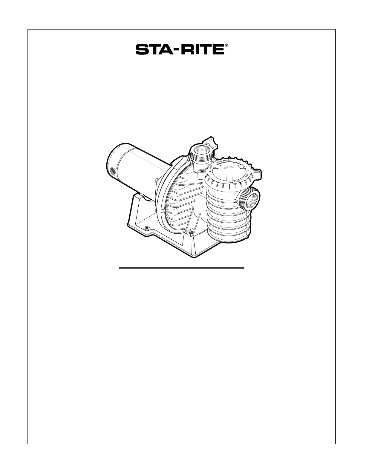
MAX-E-PRO
CENTRIFUGAL PUMPS
WITH INTEGRAL TRAP
O W N E R’ S M A N U A L
INSTALLATION, OPERATION & PARTS
Series P6RA, P6EA, P6E and P6R
See Page 2 for Model Numbers
®
This manual must be given to the owner/user of this pump
© 2
014 Pentair Water Pool and Spa, Inc. All rights reserved.
1620 Hawkins Ave., Sanford, NC 27330 • (919) 566-8000
10951 West Los Angeles Ave., Moorpark, CA 93021 • (805) 553-5000
Max-E-Pro™, Sta-Rite® are trademarks and/or registered trademarks of Pentair Water Pool and Spa, Inc. and/or its affiliated companies in the United
States and/or other countries. Unless noted, names and brands of others that may be used in this document are not used to indicate an affiliation or
endorsement between the proprietors of these names and brands and Pentair Water Pool and Spa, Inc. Those names and brands may be the
trademarks or registered trademarks of those parties or others.
5/16/14 S691 (Rev. C)
PUMP WARNINGS AND SAFETY INSTRUCTIONS
For Pool and Spa Pumps (Non SVRS Pumps)
FAILURE TO FOLLOW ALL INSTRUCTIONS AND WARNINGS CAN RESULT IN SERIOUS BODILY
INJURY OR DEATH. THIS PUMP SHOULD BE INSTALLED AND SERVICED ONLY BY A QUALIFIED POOL
SERVICE PROFESSIONAL. INSTALLERS, POOL OPERATORS AND OWNERS MUST READ THESE
WARNINGS AND ALL INSTRUCTIONS IN THE OWNER'S MANUAL BEFORE USING THIS PUMP. THESE
WARNINGS AND THE OWNER'S MANUAL MUST BE LEFT WITH THE POOL OWNER.
Warnings and safety instructions for Pentair Aquatic Systems pumps and other related products are available
at: http://www.pentairpool.com/pool-owner/safety-warnings/ Call (800) 831-7133 for additional free copies
of these instructions. Please refer to www.pentairpool.com for more information related to Pentair Aquatic
Systems pumps.
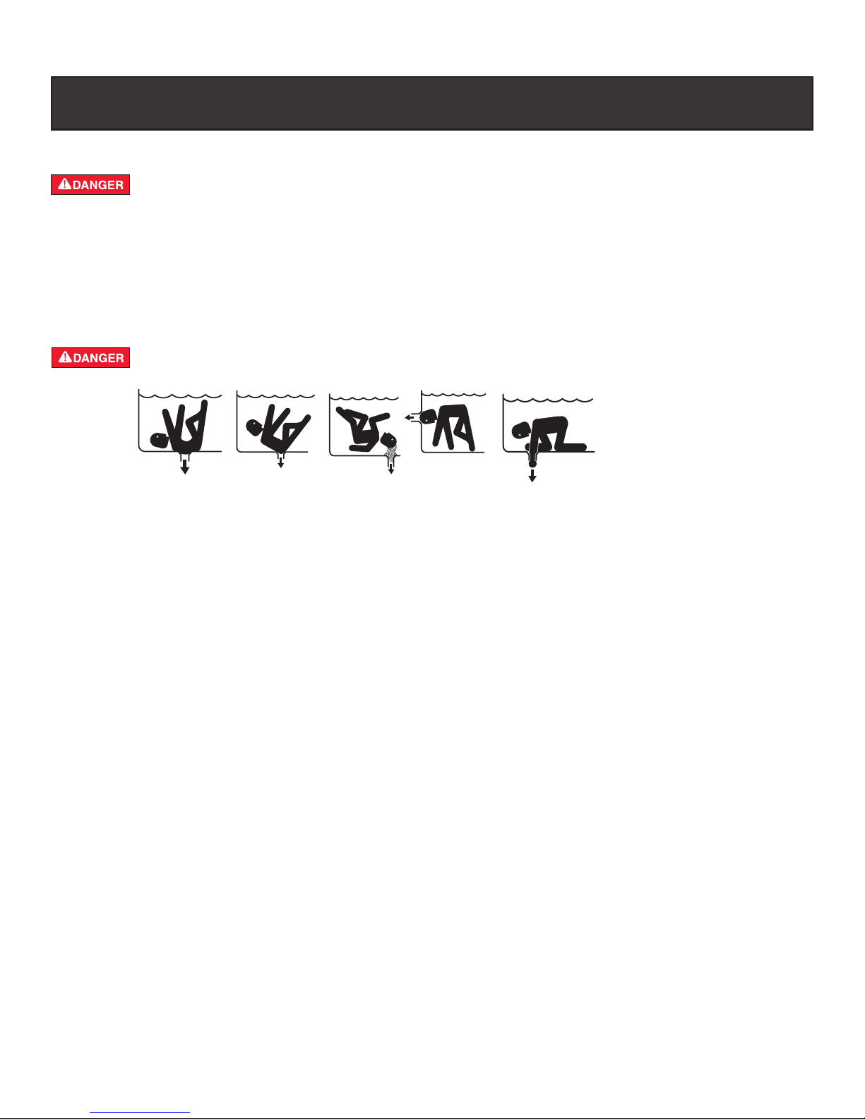
SUCTION ENTRAPMENT HAZARD: STAY OFF THE MAIN DRAIN AND AWAY FROM ALL SUCTION
OUTLETS!
F
THIS PUMP PRODUCES HIGH LEVELS OF SUCTION AND CREATES A STRONG VACUUM AT THE
MAIN DRAIN AT THE BOTTOM OF YOUR POOL AND SPA. THIS SUCTION IS SO STRONG THAT IT CAN
TRAP ADULTS OR CHILDREN UNDER WATER IF THEY COME IN CLOSE PROXIMITY TO A POOL OR
SPA DRAIN OR A LOOSE OR BROKEN DRAIN COVER OR GRATE.
THE USE OF UNAPPROVED COVERS OR ALLOWING USE OF THE POOL OR SPA WHEN COVERS ARE MISSING,
CRACKED OR BROKEN CAN RESULT IN BODY OR LIMB ENTRAPMENT, HAIR ENTANGLEMENT, BODY ENTRAPMENT, EVISCERATION AND/OR DEATH.
The suction at a pool or spa drain or outlet can cause:
Limb Entrapment: When a limb is sucked or inserted into an opening resulting in a mechanical bind or swelling. This
hazard is present when a drain cover is missing, broken, loose, cracked or not properly secured.
Hair Entanglement: When the hair tangles or knots in the
present when the flow rating of the cover is too small for the pump or pumps.
Body Entrapment: When a portion of the body is held against the drain cover trapping the swimmer underwater. This
hazard is present when the drain cover is missing, broken or the cover flow rating is not high enough for the pump or
pumps.
Evisceration/Disembowelment: When a person sits on an open pool (particularly a child wading pool) or spa outlet and
suction is applied directly to the intestines, causing severe intestinal damage. This hazard is present when the drain cover
is missing, loose, cracked, or not properly secured.
Mechanical Entrapment: When jewelry, swimsuit, hair decorations, finger, toe or knuckle is caught in an opening of an
outlet or drain cover. This hazard is present when the drain cover is missing, broken, loose, cracked, or not properly
secured.
NOTE: ALL SUCTION PLUMBING MUST BE INSTALLED IN ACCORDANCE WITH THE LATEST NATIONAL AND LOCAL
CODES FOR SWIMMING POOLS, SPAS AND HOT TUBS, INCLUDING NSPI STANDARDS AND CPSC GUIDELINES.
drain cover, trapping the swimmer underwater. This hazard is
READ AND KEEP THESE INSTRUCTIONS FOR FUTURE REFERENCE
i
PUMP (Non SVRS) WARNINGS AND SAFETY INSTRUCTIONS
TO MINIMIZE THE RISK OF INJUR Y DUE T O SUCTION ENTRAPMENT HAZARD:
• Pools and spas should utilize a minim um of two dr ains per pump.
• A properly installed and secured ANSI/ASME A112.19.8 approved anti-entrapment suction
cover must be used for each drain.
• Each suction cover must be installed at least three (3') feet apart, as measured from the
nearest point to nearest point.
• Regularly inspect all covers for cracks, damage and advanced weathering.
• If a cover becomes loose, cracked, damaged, broken or is missing, close the pool or spa
immediately, shut off the pump, post a notice and keep the pool or spa closed until an
appropriate certified cover is properly installed.
• Replace drain covers as necessary. Dr ain cov ers deteriorate ov er time due to e xposure to
sunlight, pool chemicals and weather.
• Av oid getting hair, limbs or body in close proximity to any suction cover, pool drain or outlet.
• Use a safety vacuum release system ("SVRS"), suction limiting system or automatic pump
shut-off system.
• Disable suction outlets or reconfigure into return inlets.
A clearly labeled emergency shut-off switch for the pool pump and spa jet pump must be in an easily
accessible, obvious place near the pool or spa. Make sure bathers know where it is and how to use it in case
of emergency .
The Virginia Graeme Baker (VGB) Pool and Spa Safety Act creates new requirements for owners and operators of commercial swimming
pools and spas.
Commercial pools or spas constructed on or after December 19, 2008, shall utilize:
(A) A multiple main drain system without isolation capability with suction outlet covers that meet ASME/ANSI A112.19.8a Suction Fittings
for Use in Swimming Pools, Wading Pools, Spas, and Hot Tubs and either :
(i) A safety vacuum release system (SVRS) meeting ASME/ANSI A112.19.17 Manufactured Safety Vacuum Release systems (SVRS)
for Residential and Commercial Swimming Pool, Spa, Hot Tub, and Wading Pool Suction Systems and/or ASTM F2387 Standard
Specification for Manufactured Safety Vacuum Release Systems (SVRS) for Swimming pools, Spas and Hot Tubs or
(ii) A properly designed and tested suction-limiting vent system or
(iii) An automatic pump shut-off system.
Commercial pools and spas constructed prior to December 19, 2008, with a single submerged suction outlet shall use a suction outlet cover that
meets ASME/ANSI A112.19.8a and either:
(A) A SVRS meeting ASME/ANSI A112.19.17 and/or ASTM F2387, or
(B) A properly designed and tested suction-limiting vent system, or
(C) An automatic pump shut-off system, or
(D) Disabled submerged outlets, or
(E) Suction outlets shall be reconfigured into return inlets.
HAZARDOUS PRESSURE: STAND CLEAR OF PUMP AND FIL TER DURING ST AR T-UP
Pool and spa circulation systems operate under high pressure . When any part of the circulating system (i.e.
lock ring, pump, filter , valves, etc.) is serviced, air can enter the system and become pressurized.
Pressurized air can cause the pump housing cover filter lid and valves to violently separate which can result in
severe personal injury or death. Filter tank lid and strainer cover must be properly secured to prevent violent
separation. Stand clear of all circulation system equipment when turning on or starting up pump.
CAUTION!: Electrical controls such as on/off switches, timers, and control systems , etc. should be properly
installed to allow the operation (start-up, shut-down, or servicing) of any pump or filter without requiring the user
to place any portion of his/her body over or near the pump strainer lid or filter lid. Such installation should allow
the user to stand clear of the filter and pump during system start-up, shut down or servicing of the system.
Before servicing pool and spa equipment, make note of the filter pressure. Be sure that all controls are set to
ensure the system cannot inadvertently start during service. Turn off all power to the pump. IMPORTANT:
Place filter manual air relief valve in the open position and wait for all pressure in the system to be
relieved.
Before starting the system, fully open the manual air relief valve and place all system v alves in the "open"
position to allow water to flow freely from the pool and spa back to the pool or spa. Stand clear of all pool and
spa equipment and start the pump. IMPOR TANT : Do not c lose filter manual air relief valve until all
pressure has been discharged from the valve and a steady stream of water appears. Observe filter
pressure gauge and be sure it is not higher than the pre-service condition.
ii
2
‘P6RA’, P6EA’ ‘P6E’ and
‘P6R’ SERIES PUMP
WITH TRAP
To avoid unneeded service calls, prevent possible
injuries, and get the most out of your pump, READ THIS
MANUAL CAREFULLY!
The Sta-Rite ‘P6RA’, ‘P6EA’, ‘P6R’ and ‘P6E’ Series
Self-priming Centrifugal pumps:
• Are designed for use with swimming pools or as
centrifugal pumps.
Table of Contents
Safety instructions 2-3
Installation 3-5
Electrical 5-8
Operation 9-11
Storage/Winterizing 10
Pump Service 10-11
Troubleshooting Guide 12
Repair Parts List 13-15
READ AND FOLLOW
SAFETY INSTRUCTIONS!
This is the safety alert symbol. When you see this
symbol on your system or in this manual, look for
one of the following signal words and be alert to the
potential for personal injury.
warns about hazards that will cause death,
serious personal injury, or major property damage if
ignored.
warns about hazards that can cause death,
serious personal injury, or major property damage if
ignored.
warns about hazards that will or can cause
minor personal injury or property damage if ignored.
NOTICE indicates special instructions not related to
hazards.
Carefully read and follow all safety instructions in this
manual and on equipment. Keep safety labels in good
condition; replace if missing or damaged.
Incorrectly installed or tested equipment
may fail, causing severe injury or property
damage.
Read and follow instructions in owner's manual when
installing and operating equipment. Have a trained pool
professional perform all pressure tests.
1. Do not connect system to a high pressure or city
water system.
Technical Support
Sanford, North Carolina
(8 A.M. to 4:30 P.M. EST)
Moorpark, California
(8 A.M. to 4:30 P.M. PST)
Phone: (800) 831-7133
Fax: (800) 284-4151
www.pentairpool.com www.staritepool.com
Max-E-Pro® Pump Models
2. Use equipment only in a pool or spa installation.
3. Install pump with at least two (2) hydraulically
balanced main drains equipped with correctly
installed, screw-fastened, anti-entrapment certified
covers. See Page 4.
4. Trapped air in system can cause
property damage. BE SURE all air
is out of system before operating or testing equipment
and/or personal injury.
Before pressure testing, make the following safety
checks:
• Check all clamps, bolts, lids, and system accessories
before testing.
• Release all air in system before testing.
• Water pressure for test must be less than 25 PSI
(7.5 kg/cm2).
• Water Temperature for test must be less than 100oF
(38oC).
• Limit test to 24 hours. After test, visually check
system to be sure it is ready for operation. Remove
trap lid and retighten hand tight only.
NOTICE: These parameters apply to Sta-Rite
equipment only. For non-Sta-Rite equipment, consult
manufacturer.
INSTALLATION
Only qualified, licensed personnel should install pump
and wiring.
Pump mount must:
Be located away from corrosive or flammable
chemicals.
Have enough ventilation to maintain air temperature at
less than the maximum ambient temperature rating (Max.
Amb.) listed on the motor model plate. If this pump is
installed in an enclosure/pump house, the enclosure must
have adequate ventilation and air circulation to keep the
temperature in the enclosure at or below the motor’s rated
ambient temperature whenever the pump is running.
Be solid - Level - Rigid - Vibration free - Noncombustible. (To reduce vibration and pipe stress, bolt
pump to mount.)
Allow pump suction inlet height to be as close to water
level as possible.
Allow use of short, direct suction pipe (To reduce friction
losses).
Allow for gate valves in suction and discharge piping.
Have adequate floor drainage to prevent flooding.
Be protected from excess moisture.
Allow adequate access for servicing pump and piping.
3
IMPORTANT SAFETY
INSTRUCTIONS
Always follow basic safety precautions with this
equipment, including the following.
To reduce the risk of injury, do not
permit children to use this product.
This pump is for use with permanently
installed pools and may also be used with hot tubs
and spas if so marked. Do not use with storable
pools. A permanently installed pool is constructed in
or on the ground or in a building such that it cannot
be readily disassembled for storage. A storable pool
is constructed so that it may be readily disassembled
for storage and reassembled to its original integrity.
SAVE THESE
INSTRUCTIONS
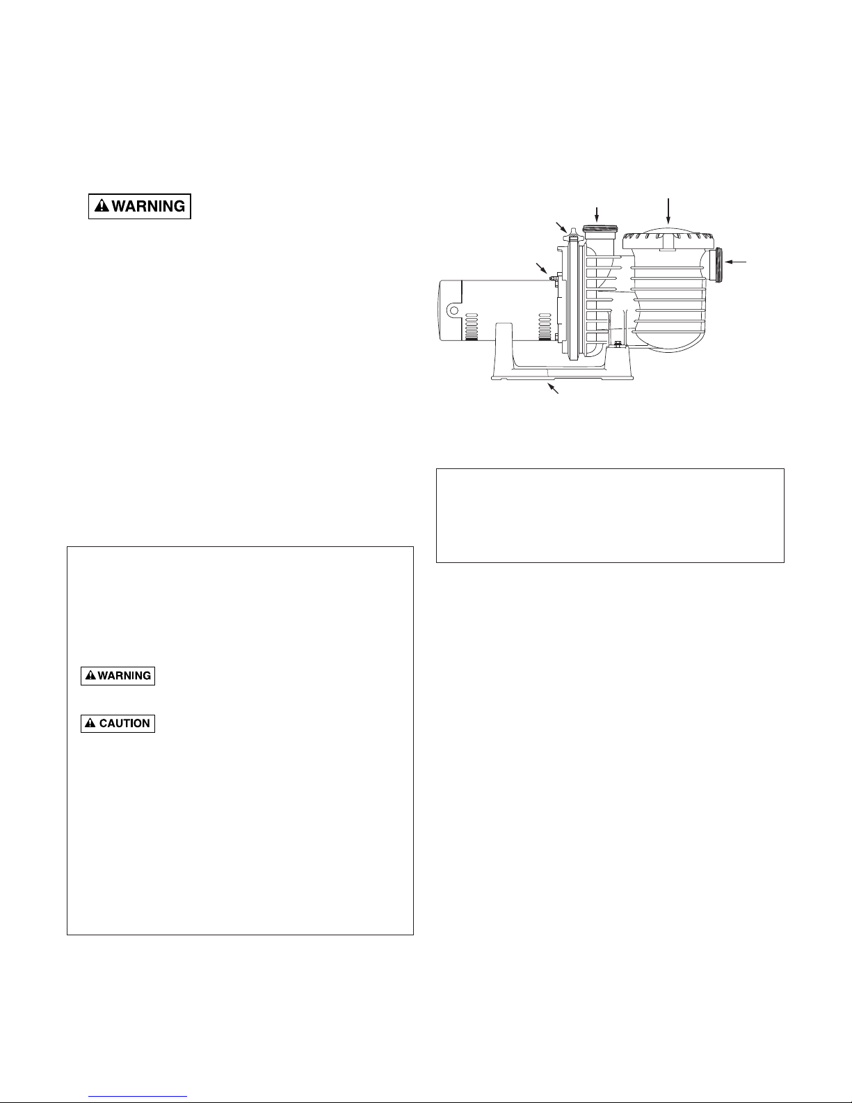
Suction
Por t
from
pool or
vacuum
filters
Strainer Basket
cover
Discharge Port
to filter
or pool
Clamp
Knob
Bonding Lug
Pump may be bol ted to level
foundation or mounting bracket
4284 1102
Figure 1
NOTICE: Port threads are: Internal - 2" NPT for direct
connection to pipe. External - 3-1/4" Buttress. Fits Sta-Rite
U11-200P Union Collar for quick disconnect pipe connection.
See Page 13 for Union Kits.
4
Fire and burn hazard. Modern motors run at
high temperatures. To reduce the risk of fire, do not allow
leaves, debris, or foreign matter to collect around the
pump motor. To avoid burns when handling the motor, let
it cool for 20 minutes before trying to work on it.
NOTICE: Use thread seal tape for making all threaded
connections to the pump. Do not use pipe dope; pipe
dope will cause stress cracking in the pump.
NOTICE: Pump suction and discharge connections have
molded in thread stops. DO NOT try to screw pipe in
beyond these stops.
Taping Instructions:
Use only new or clean PVC pipe fittings.
Wrap male pipe threads with one to two layers of thread
seal tape. Cover entire threaded portion of pipe.
Do not overtighten or tighten past thread stop in pump port!
If leaks occur, remove pipe, clean off old tape, rewrap
with one to two additional layers of tape and remake the
connection.
NOTICE: Support all piping connected with pump!
Piping:
Use at least 2" IPS PVC (51mm) pipe. Increase size if a
long run is needed.
To avoid strains on the pump, support both suction and
discharge pipes independently. Place these supports
near the pump.
To avoid a strain left by a gap at the last connection, start
all piping at the pump and run pipe away from the pump.
Never use a suction pipe smaller than pump suction
connection.
To avoid airlocking, slope suction pipe slightly upward
toward the pump.
NOTICE: To prevent flooding when removing pump for
service, all flooded suction systems must have gate
valves in suction and discharge pipes.
Fittings:
Fittings restrict flow; for best efficiency use fewest
possible fittings.
Avoid fittings which could cause an air trap.
Pool fittings must conform to International Association of
Plumbing and Mechanical Officials (IAPMO) standards.
Use only non-entrapping suction fitting or double
suction.
POOL PUMP SUCTION
REQUIREMENTS
Pump suction is hazardous and can trap and
drown or disembowel bathers. Do not use or operate
swimming pools, spas, or hot tubs if a suction outlet cover
is missing, broken, or loose. Follow the guidelines below
for a pump installation which minimizes risk to users of
pools, spas, and hot tubs.
Entrapment Protection
The pump suction system must provide protection against
the hazard of suction entrapment or hair
entrapment/entanglement.
Suction Outlet Covers
All suction outlet covers must be maintained. They must
be replaced if cracked, broken, or missing.
See below for outlet cover certification requirements.
All suction outlets must have correctly installed, screw-
fastened covers in place.
Testing and Certification
Suction outlet covers must have been tested by a
nationally recognized testing laboratory and found to
comply with the latest ASME/ANSI Specification for
Suction Fittings For Use in Swimming Pools, Spas, Hot
Tubs, and Whirlpool Bathtub Applications.
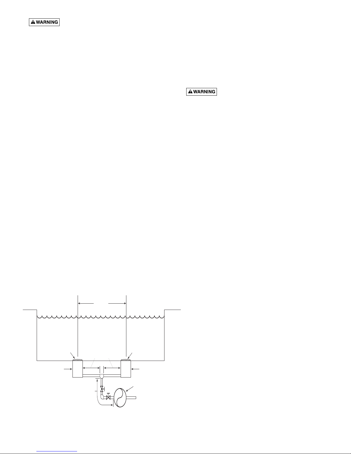
Outlets Per Pump
Provide at least two hydraulically balanced main drains,
with covers (see Page 5), for each swimming pool pump
suction line. The centers of the main drains (suction
fittings) must be at least three feet apart.
The system must be built so that it cannot operate with
the pump drawing water from only one main drain (that is,
there must be at least two main drains connected to the
pump whenever it is running). (See Figure 2). However, if
two main drains run into a single suction line, the single
suction line may be equipped with a valve which will
shutoff both main drains from the pump (see Figure 2).
More than one pump can be connected to a single
suction line as long as the requirements above are met.
At Least
3 Feet
Suction Outlet
(Main Drain)
Suction Outlet
(Main Drain)
IAPMO Certified
Anti-entrapment
Cover or Suction Fitting,
screw-fastened to
Main Drain Sump
IAPMO Certified
Anti-entrapment
Cover or Suction Fitting,
screw-fastened to
Main Drain Sump
Pump
Valves OK between
pump and Tee
No valves between
Tee and Main Drains
2762 0197
Figure 2 – Recommended pump suction layout.
 Loading...