

STA-RITE P6RA6E-205L, P6E6C-204L, P6E6F-207L, P6RA6F-206L, P6RA6YF-206L Owner's Manual
...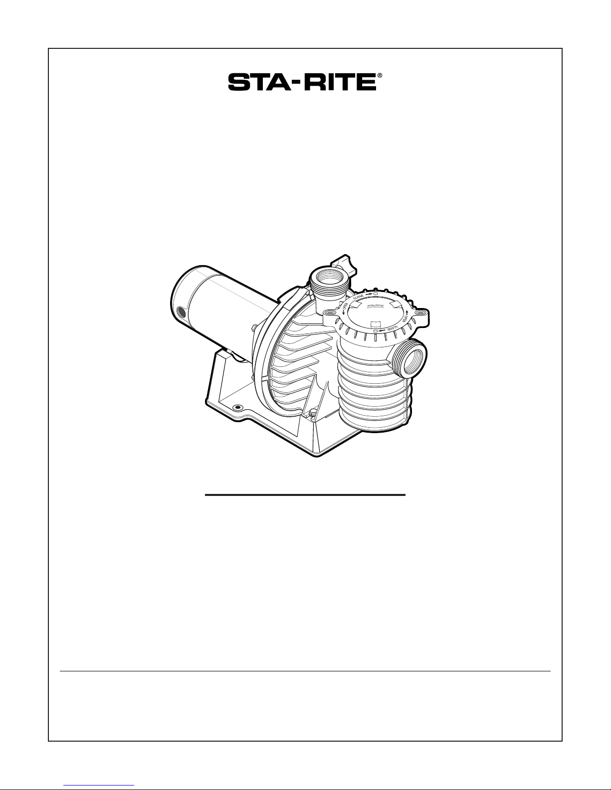
MAX-E-PRO
TM
CENTRIFUGAL PUMPS
WITH INTEGRAL TRAP
O W N E R’ S M A N U A L
INSTALLATION, OPERATION & PARTS
Series P6E and P6RA
See Page 2 for Model Numbers
Sta-Rite Pool/Spa Group
293 Wright Street, Delavan, WI 53115
International: 262-728-5551, FAX: 262-728-7550
www.starite.com
Union City, TN • Delavan, WI • Mississauga, Ont. • Murrieta, CA
© 2003, Sta-Rite Industries, Inc. Printed in U.S.A. S691 (Rev. 10/30/03)
This manual should be furnished to
the end user of this pump; its use will
reduce service calls and chance of
injury and will lengthen pump life.

2
‘P6RA’ and ‘P6E’ SERIES PUMP
WITH TRAP
To avoid unneeded service calls, prevent possible injuries, and get the most
out of your pump, READ THIS MANUAL CAREFULLY!
The Sta-Rite ‘P6RA’ and ‘P6E’ Series Self-priming Centrifugal pumps:
• Are designed for use with swimming pools or as centrifugal pumps.
• Are excellent performers; durable, reliable.
Table of Contents
Safety Instructions ........................................................................................3
Installation.................................................................................................4-6
Electrical....................................................................................................6-8
Operation ................................................................................................9-10
Storage/Winterizing ....................................................................................10
Pump Service.........................................................................................11-12
Troubleshooting Guide ...............................................................................13
Repair Parts List .....................................................................................14-15
Warranty.....................................................................................................16
Max-E-ProTMPump Models
HP 2-Speed
1/2 P6E6C-204L
3/4 P6E6D-205L
1 P6E6E-206L P6RA6E-205L
1-1/2 P6E6F-207L P6RA6F-206L P6RA6YF-206L
2 P6E6G-208L P6RA6G-207L P6RA6YG-207L
3 P6E6H-209L
3
READ AND FOLLOW SAFETY
INSTRUCTIONS!
This is the safety alert symbol. When you see this symbol on your system
or in this manual, look for one of the following signal words and be alert
to the potential for personal injury.
warns about hazards that will cause death, serious personal
injury, or major property damage if ignored.
warns about hazards that can cause death, serious personal
injury, or major property damage if ignored.
warns about hazards that will or can cause minor personal injury
or property damage if ignored.
NOTICE indicates special instructions not related to hazards.
Carefully read and follow all safety instructions in this manual and on equipment. Keep safety labels in good condition; replace if missing or damaged.
Incorrectly installed or tested equipment may fail, causing
severe injury or property damage.
Read and follow instructions in owner's manual when installing
and operating equipment. Have a trained pool professional per-
form all pressure tests.
1. Do not connect system to a high pressure or city water system.
2. Use equipment only in a pool or spa installation.
3. Install pump with at least 2 hydraulically balanced main drains equipped
with correctly installed, screw-fastened, anti-entrapment certified covers.
See Page 5.
4. Trapped air in system can cause explosion. BE SURE all air is out of system
before operating or testing equipment.
Before pressure testing, make the following safety checks:
• Check all clamps, bolts, lids, and system accessories before testing.
• Release all air in system before testing.
• Water pressure for test must be less than 25 PSI (7.5 kg/cm
2
).
• Water Temperature for test must be less than 100oF. (38oC).
• Limit test to 24 hours. After test, visually check system to be sure it is ready
for operation. Remove trap lid and retighten hand tight only.
NOTICE: These parameters apply to Sta-Rite equipment only. For
non-Sta-Rite equipment, consult manufacturer.
INSTALLATION
Only qualified, licensed personnel should install pump and wiring.
Pump mount must:
Be located away from corrosive or flammable chemicals.
IMPORTANT
SAFETY
INSTRUCTIONS
Always follow basic safety precautions with this equipment, including the following.
To reduce the risk of
injury, do not permit children to
use this product unless they are
closely supervised at all times.
This pump is for use
with permanently installed pools
and may also be used with hot
tubs and spas if so marked. Do
not use with storable pools. A
permanently installed pool is constructed in or on the ground or in
a building such that it cannot be
readily disassembled for storage.
A storable pool is constructed so
that it may be readily disassembled for storage and reassembled
to its original integrity.
SAVE THESE
INSTRUCTIONS
4
Have enough ventilation to maintain air temperature at less than the maximum
ambient temperature rating (Max. Amb.) listed on the motor model plate. If this
pump is installed in an enclosure/pump house, the enclosure must have adequate ventilation and air circulation to keep the temperature in the enclosure at
or below the motor’s rated ambient temperature whenever the pump is running.
Be solid - Level - Rigid - Vibration free - Non-combustible. (To reduce
vibration and pipe stress, bolt pump to mount.)
Allow pump suction inlet height to be as close to water level as possible.
Allow use of short, direct suction pipe (To reduce friction losses).
Allow for gate valves in suction and discharge piping.
Have adequate floor drainage to prevent flooding.
Be protected from excess moisture.
Allow adequate access for servicing pump and piping.
Fire and burn hazard. Modern motors run at high temperatures.
To reduce the risk of fire, do not allow leaves, debris, or foreign matter to collect around the pump motor. To avoid burns when handling the motor, let it
cool for 20 minutes before trying to work on it.
NOTICE: Use Teflon tape or Plasto-Joint Stik
1
for making all threaded connections to the pump. Do not use pipe dope; pipe dope will cause stress cracking
in the pump.
NOTICE: Pump suction and discharge connections have molded in thread
stops. DO NOT try to screw pipe in beyond these stops.
Teflon Taping Instructions:
Use only new or clean PVC pipe fittings.
Wrap male pipe threads with one to two layers of Teflon tape. Cover entire
threaded portion of pipe.
Do not overtighten or tighten past thread stop in pump port!
If leaks occur, remove pipe, clean off old tape, rewrap with one to two addi-
tional layers of tape and remake the connection.
NOTICE: Support all piping connected with pump!
1
Lake Chemical Co., Chicago, Illinois
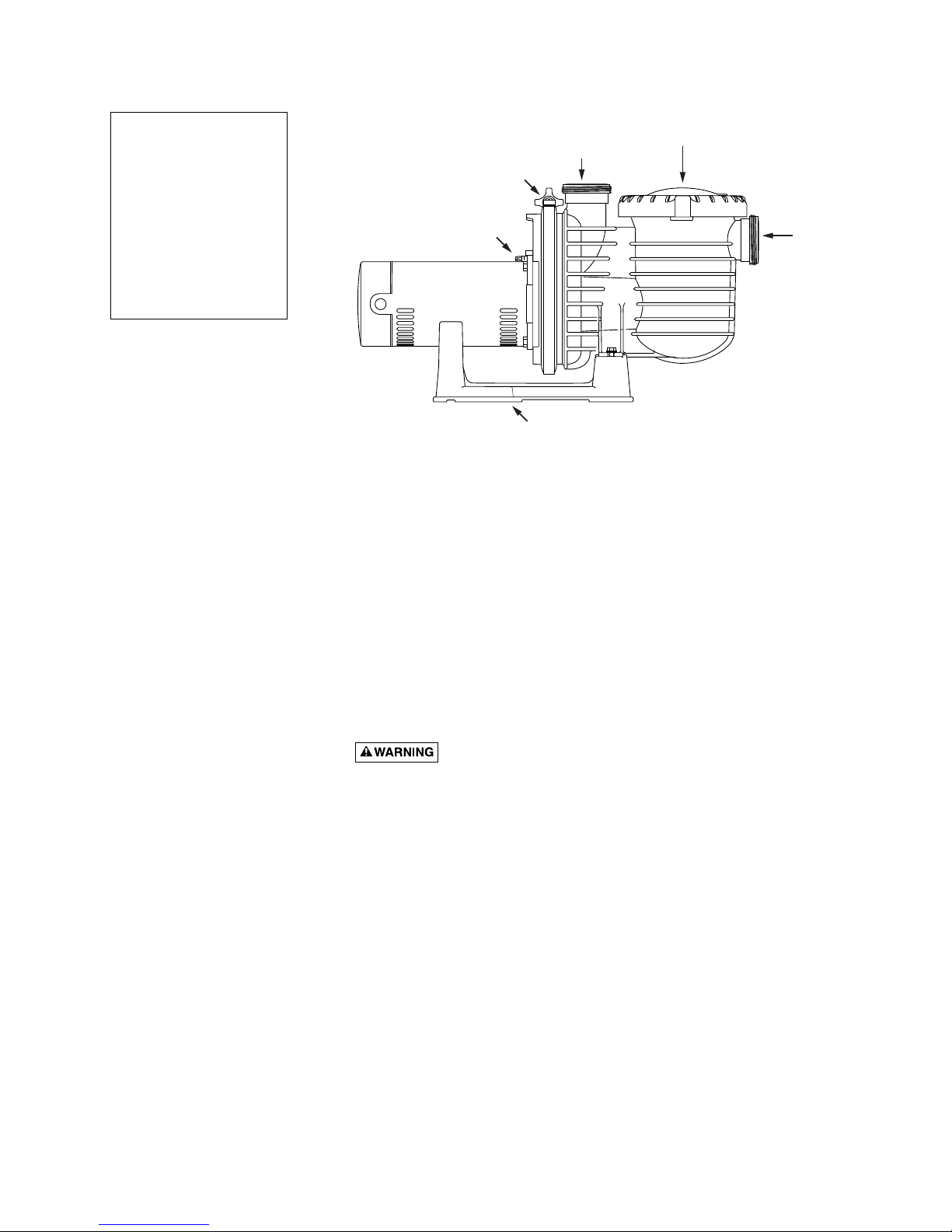
Figure 1
NOTICE: Port threads
are: Internal - 2" NPT
for direct connection to
pipe. External - 3-1/4"
Buttress. Fits Sta-Rite
U11-200P Union Collar
for quick disconnect
pipe connection.
See Page 14 for Union
Kits.
Strainer Basket
cover
Suction
Port
from
pool or
vacuum
filters
4284 1102
Bonding Lug
Discharge Port
to filter
Clamp
Knob
or pool
Pump may be bolted to level
foundation or mounting bracket
5
Piping:
Use at least 2" IPS PVC (51mm) pipe. Increase size if a long run is needed.
To avoid strains on the pump, support both suction and discharge pipes inde-
pendently. Place these supports near the pump.
To avoid a strain left by a gap at the last connection, start all piping at the
pump and run pipe away from the pump.
Never use a suction pipe smaller than pump suction connection.
To avoid airlocking, slope suction pipe slightly upward toward the pump.
NOTICE: To prevent flooding when removing pump for service, all flooded
suction systems must have gate valves in suction and discharge pipes.
Fittings:
Fittings restrict flow; for best efficiency use fewest possible fittings.
Avoid fittings which could cause an air trap.
Pool fittings must conform to International Association of Plumbing and
Mechanical Officials (IAPMO) standards.
Use only non-entrapping suction fitting or double suction.
POOL PUMP SUCTION
REQUIREMENTS
Pump suction is hazardous and can trap and drown or disembowel bathers. Do not use or operate swimming pools, spas, or hot tubs if a
suction outlet cover is missing, broken, or loose. Follow the guidelines below
for a pump installation which minimizes risk to users of pools, spas, and hot
tubs.
Entrapment Protection
The pump suction system must provide protection against the hazard of
suction entrapment or hair entrapment/entanglement.
Suction Outlet Covers
All suction outlet covers must be maintained. They must be replaced if
cracked, broken, or missing.
See below for outlet cover certification requirements.
All suction outlets must have correctly installed, screw-fastened covers in
place.
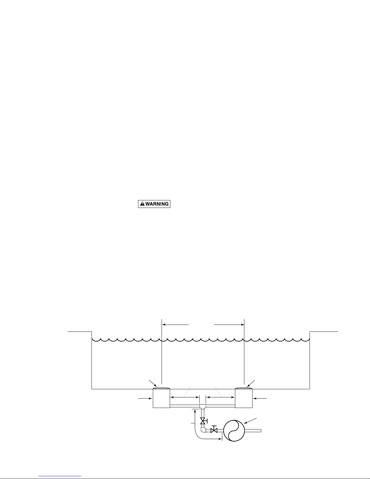
Figure 2 – Recommended pump suction layout.
IAPMO Certified
Anti-entrapment
Cover or Suction Fitting,
screw-fastened to
Main Drain Sump
Suction Outlet
(Main Drain)
Valves OK between
pump and Tee
At Least
3 Feet
No valves between
Tee and Main Drains
IAPMO Certified
Anti-entrapment
Cover or Suction Fitting,
screw-fastened to
Main Drain Sump
Suction Outlet
(Main Drain)
Pump
2762 0197
 Loading...