

Page 1
Compool® to EasyTouch
S
SOLAR
P
.
.
O
.
r
.
ool
pa
y)
n
U
S
CT
eset
Upgrade
1
2
3
4AUX 5
6
7
U
O
S 9
5 / 100
090
S
SOLAR
.
.
O
.
r
.
ool
pa
y)
n
U
S
CT
ese
Upgrade
1
2
3
4
5
6AUX 7
U
O
S 9
5 / 100
090
Pool and Spa Control System Upgrade
MODES OF OPERATION
Auto:
Indoor control panel and other remote devices operate system
Service buttons on this panel operate system
ther remote devices are disabled
Time Out:
Service buttons on this panel operate equipment fo
three hours, then settings return to Auto mode
N
MEN
ELE
PUM
P
S
AUX
Fill (Spillwa
Drai
VALVE
AUX
AUX
AUX
R
AUX
AUX
MODES OF OPERATION
Auto:
Indoor control panel and other remote devices operate system
Service buttons on this panel operate system
ther remote devices are disabled
Time Out:
Service buttons on this panel operate equipment fo
three hours, then settings return to Auto mode
N
MEN
ELE
PUMP
P
S
AUX
Fill (Spillwa
Drai
VALVE
AUX
AUX
AUX
AUX
R
t
AUX
®
Installation and User’s Guide
IMPORTANT SAFETY INSTRUCTIONS
READ AND FOLLOW ALL INSTRUCTIONS
SAVE THESE INSTRUCTIONS
Page 2
IMPORTANT INFORMATION
How to change your Compool/EasyTouch Upgrade
system to a “Single Body” system
Configuring Compool/EasyTouch as a SINGLE BODY SYSTEM
The Compool EasyTouch Upgrade circuit board is factory configured and ready to operate as a
SHARED EQUIPMENT system (Jumper J25 = ON). To change the Compool EasyTouch Upgrade board
to operate a SINGLE BODY system, first remove Jumper 25 (place the jumper on one of the pins) and
erase the EEPROM (see page 49).
To change Compool EasyTouch circuit board:
Getting There
MENU ▼ SETTINGS ▼ Erase EEPROM Erase EEPROM
1. Write down your Compool system settings and connections (e.g. filter pump schedules,
auxiliary connection for lights, spa jets etc.).
2. Change system to SINGLE BODY system (jumper OFF): Remove circuit board Jumper
J25. Place the jumper on one of the pins. J25 is located in the upper/center of the circuit
board (see page 76).
▲
3. Erase the circuit board EEPROM: Power up the Compool EasyTouch Upgrade circuit
board. To erase the EEPROM, press MENU > SETTINGS > Erase EEPROM and follow
the screen prompts as shown below:
Erase EEPROM
Erase ALL? No (Yes)
Erase EEPROM
Are You Sure?
No (Yes)
AUTO HEATER
SPA 95°F / 100°F
AIR 70°F
MON 09:30 AM
Up/Down button: Select Yes.
Right button: The message “Erase EEPROM Are You Sure? No” is
displayed.
Up/Down button: Select Yes.
Right button: Press this button to erase system data and restore the
factory defaults. The display will go blank, then the main screen will be
displayed.
4. Continue to setup your system using the EasyTouch menu (see page 14).
© 2010 Pentair Water Pool and Spa, Inc. All rights reserved.
1620 Hawkins Ave., Sanford, NC 27330 • (919) 566-8000
10951 West Los Angeles Ave., Moorpark, CA 93021 • (800) 553-5000
EasyTouch®, Compool®, IntelliChlor®, IntelliFlo®, MagicStream®, ThermalFlo®, QuickTouch®, IntelliBrite®,
SAm®, SAL®, FIBER
registered trademarks of Pentair Water Pool and Spa, Inc. and/or its affiliated companies in the United States and/
or other countries. Unless noted, names and brands of others that may be used in this document are not used to
indicate an affiliation or endorsement between the proprietors of these names and brands and Pentair Water Pool
and Spa, Inc. Those names and brands may be the trademarks or registered trademarks of those parties or others.
P/N 521102 - Rev B - 03/15/2010
works
®, Photon Generator®, and Pentair Water Pool and Spa® are trademarks and/or
Page 3

Contents
IMPORTANT SAFETY PRECAUTIONS ........................................................................................................ iii
EasyTouch System Kit Contents ................................................................................................................... v
Accessory Equipment ................................................................................................................................... v
Technical Support ......................................................................................................................................... v
How to Change the system to a SINGEL BODY system ............................................................................ v
Section 1 - Compool to EasyTouch Pool and Spa Control System Upgrade Overview .......................... 1
Compool® EasyTouch® Pool and Spa Control System Upgrade Overview.................................................... 1
Compool upgrade systems ....................................................................................................................... 1
Operating EasyTouch .................................................................................................................................... 1
IntelliChlor® Electronic Chlorine Generator.................................................................................................... 1
Compool EasyTouch Upgrade System Overview........................................................................................... 2
Compool EasyTouch Upgrade Control Panel .................................................................................................. 3
Comppol/EasyTouch Upgrade Controls and Buttons ...................................................................................... 3
iS4 Spa-Side Remote Controller (Optional) .................................................................................................... 6
QuickTouch® QT4 Wireless Controller (Optional) .......................................................................................... 6
iS10 Spa-Side Remote Controller (Optional) .................................................................................................. 6
EasyTouch Indoor and Wireless Control Panel (Optional)............................................................................... 7
Compool/EasyTouch Upgrade Outdoor Control Panel Operating Modes......................................................... 8
Quick Start - Spa and Pool Operations (Shared Equipment).......................................................................... 9
Heat your spa or pool .................................................................................................................................... 9
Adjust your spa or pool heat settings ........................................................................................................ 9
Switch on lights manually and synchronize light colors ................................................................................. 10
Using the Once Only timer feature ................................................................................................................ 10
Schedule start and stop times for equipment ................................................................................................ 11
Program your Spa or Pool ......................................................................................................................... 11
Schedules ..................................................................................................................................................... 11
Setting the Egg Timer Feature .................................................................................................................. 12
Section 2 - Setting up the Compool/EasyTouch Upgrade System ........................................................... 13
EasyTouch Menus ........................................................................................................................................ 14
Main Screen .................................................................................................................................................. 16
Feature Circuits Menu ................................................................................................................................... 17
Lights Menu .................................................................................................................................................. 18
The Color Swim and Color Set Lighting Features ...................................................................................... 18
Setting up Lights....................................................................................................................................... 19
Assign the Light Circuit Name and Function ............................................................................................. 19
Setting up IntelliBrite Light Circuits ............................................................................................................... 20
Lights Menu .............................................................................................................................................. 20
Modes (IntelliBrite Color light shows, Color Swim, Color Set) .................................................................... 20
Modes (Color Swim).................................................................................................................................. 20
Modes (Color Set) ..................................................................................................................................... 21
Colors ....................................................................................................................................................... 21
Hold/Recall ............................................................................................................................................... 21
All On / All Off (Lights Menu) .................................................................................................................... 21
Sync ......................................................................................................................................................... 21
Setting up SAM, SAL, PG2000, Color Wheel Lights.................................................................................. 22
Config ....................................................................................................................................................... 22
Setting up MagicStream Laminars ................................................................................................................ 23
Using the MagicStream Laminar Features ................................................................................................ 24
Heat Menu .................................................................................................................................................... 25
Pool Temp/Src ........................................................................................................................................... 25
Spa Temp/Src ........................................................................................................................................... 25
Delay Cancel Menu ....................................................................................................................................... 26
i
Compool/EasyTouch Pool and Spa Control System Upgrade Installation and User’s Guide
Page 4

ii
Contents (Continued)
Schedules Menu ........................................................................................................................................... 27
Using the Schedules menu ....................................................................................................................... 27
Schedule your spa/pool pump to turn on ................................................................................................... 28
Using the Once Only feature..................................................................................................................... 29
Using the Egg Timer (countdown) Feature ................................................................................................. 30
Settings Menu: Clock .................................................................................................................................... 31
Settings Menu: IntelliFlo® VS and VF .......................................................................................................... 32
IntelliFlo® VS pump ...................................................................................................................................... 32
IntelliFlo® VS pump ...................................................................................................................................... 33
Settings Menu: IntelliChlor ............................................................................................................................ 35
Settings Menu: ThermalFlo® Heat Pump ...................................................................................................... 36
Settings Menu: Circuit Names ....................................................................................................................... 37
Hi-Temp/Lo-Temp Controls for Single Body System ...................................................................................... 37
EasyTouch Circuit Names ............................................................................................................................. 38
Settings Menu: Circuit Functions................................................................................................................... 39
Freeze Protection .......................................................................................................................................... 39
Preset Circuit Functions ................................................................................................................................ 40
Settings Menu: Custom Names..................................................................................................................... 41
Settings Menu: Valves................................................................................................................................... 41
Settings Menu: 2-Speed Pump ...................................................................................................................... 42
Settings Menu: Solar ..................................................................................................................................... 42
Settings Menu: Delays .................................................................................................................................. 43
Settings Menu: F° / C° (Fahrenheit/Celsius) .................................................................................................. 44
Settings Menu: iS4 Spa-Side Remote Controller ........................................................................................... 44
Settings Menu: iS10 Spa-Side Remote Controller .......................................................................................... 45
Settings Menu: iSx Pump Cntrl ..................................................................................................................... 46
Assign iSx Pump Cntrl ............................................................................................................................. 46
Settings Menu: QuickTouch (QT4) Wireless Remote ..................................................................................... 47
Settings Menu: Man Heat (Off/On) ...............................................................................................
Settings Menu: Calibration ............................................................................................................................ 48
Settings Menu: Erase EEPROM (Erase System Memory) ............................................................................ 49
Settings Menu: Set Password ....................................................................................................................... 49
Settings Menu: Wireless Addr ....................................................................................................................... 50
Spa Side [Off/On] ......................................................................................................................................... 51
Diagnostics Menu: Software Rev................................................................................................................... 51
Diagnostics Menu: Bootloader Rev ................................................................................................................ 51
Diagnostics Menu: Self Test .......................................................................................................................... 52
Diagnostics Menu: Chlorinator ....................................................................................................................... 53
Diagnostics Menu: Water Temp ...................................................................................................................... 53
Diagnostics Menu: Solar Temp ...................................................................................................................... 53
Diagnostics Menu: Air Temp .......................................................................................................................... 54
Diagnostics Menu: Cir Name: [Off/On] .......................................................................................................... 54
Diagnostics Menu: Reset System ................................................................................................................. 54
Diagnostics Menu: Flash Update ................................................................................................................... 54
................. 48
Section 3 - Troubleshooting ....................................................................................................................... 55
Troubleshooting ............................................................................................................................................. 55
Frequently Asked Questions (FAQ) ............................................................................................................... 55
EasyTouch Error Messages .......................................................................................................................... 56
Self Test Error Codes .................................................................................................................................... 56
Error Code Table ............................................................................................................................................ 56
Maximum Programs Exceeded ..................................................................................................................... 57
IntelliChlor Error Messages ........................................................................................................................... 57
System Problem Diagnosis ........................................................................................................................... 58
Compool/EasyTouch Pool and Spa Control System Upgrade Installation and User’s Guide
Page 5

Contents (Continued)
First Time System Start-Up .......................................................................................................................... 61
System Test .................................................................................................................................................. 61
Testing the Auxiliary Relays .......................................................................................................................... 61
Setting up the EasyTouch wireless control panel for the first time ................................................................. 62
Setting up the EasyTouch wireless control panel ........................................................................................... 62
Synchronizing control panels ........................................................................................................................ 63
Wiring ThermalFlo to EasyTouch ................................................................................................................... 63
Wiring Description ......................................................................................................................................... 63
Section 4 - Compool/EasyTouch Upgrade Kit Installation ........................................................................ 65
Compool/EasyTouch Upgrade Kits ................................................................................................................ 65
Compool/EasyTouch Upgrade Models
Compool/EasyTouch Upgrade Models (Single Body Systems) ................................................................ 66
Compool/EasyTouch Upgrade Models (Shared Equipment Systems) ...................................................... 67
Installing Compool/EasyTouch Upgrade Control Panel (with or without Transformer Kit) ................................. 68
Compool Power Center (without sub-panel) .................................................................................................... 68
Compool Load Center (with breaker sub-panel) .............................................................................................. 72
Installing the Compool/EasyTouch Upgrade Control Panel
(Compool Load Center with sub-panel) .......................................................................................................... 74
Compool/EasyTouch Upgrade Circuit board Wiring Diagram ......................................................... 76
Compool 3810 Circuit board Wiring Diagram ................................................................................. 77
iii
Compool/EasyTouch Pool and Spa Control System Upgrade Installation and User’s Guide
Page 6
iv
IMPORTANT WARNINGS AND SAFETY PRECAUTIONS
SERIOUS BODILY INJURY OR DEATH CAN RESULT IF THIS PRODUCTIS NOT INSTALLED AND
USED CORRECTLY.
INSTALLERS, POOL OPERATORS AND POOL OWNERS MUST READ THESE WARNINGS AND
ALL INSTRUCTIONS BEFORE USING THIS PRODUCT.
This control system is intended for use in swimming pool applications.
Most states and local codes regulate the construction, installation, and operation of public pools and
spas, and the construction of residential pools and spas. It is important to comply with these codes,
many of which directly regulate the installation and use of this product. Consult your local building and
health codes for more information.
IMPORTANT NOTICE - Attention Installer: This Installation and User’s Guide (“Guide”) contains important
information about the installation, operation and safe use of this product. This Guide should be given to the
owner and/or operator of this equipment.
Before installing this product, read and follow all warning notices and instructions in this Guide.
Failure to follow warnings and instructions can result in severe injury, death, or property damage. Call
(800) 831-7133 for additional free copies of these instructions. Please refer to www.pentair.com for
more information related to this product.
Water temperature in excess of 100° F (37.7° C) may be hazardous to your health. Prolonged immersion
in hot water may induce hyperthermia. Hyperthermia occurs when the internal temperature of the body
reaches a level several degrees above normal body temperature of 98.6° F. (37° C.). Effects of
hyperthermia include: (1) Unawareness of impending danger. (2) Failure to perceive heat. (3) Failure to
recognize the need to leave the spa. (4) Physical inability to exit the spa. (5) Fetal damage in pregnant
women. (6) Unconsciousness resulting in danger of drowning. The use of alcohol, drugs, or medication
can greatly increase the risk of fatal hyperthermia in hot tubs and spas.
To reduce the risk of injury, do not permit children to use or operate this sand filter.
When setting up pool water turnovers or flow rates the operator must consider local codes governing
turnover as well as disinfectant feed ratios.
DO NOT increase pump size; this will increase the flow rate through the system and may exceed the
maximum flow rate stated on the drain cover.
Water temperature in excess of 100 degrees Fahrenheit may be hazardous to your health. Prolonged
immersion in hot water may induce hyperthermia. Hyperthermia occurs when the internal temperature
of the body reaches a level several degrees above normal body temperature of 98.6° F (37° C). The
symptoms of hyperthermia include drowsiness, lethargy, dizziness, fainting, and an increase in the
internal temperature of the body. The effects of hyperthermia include: 1) Unawareness of impending
danger. 2) Failure to perceive heat. 3) Failure to recognize the need to leave the spa. 4) Physical
inability to exit the spa. 5) Fetal damage in pregnant women. 6) Unconsciousness resulting in danger
of drowning.
To reduce the risk of injury, do not permit children to use this product unless they are closely
supervised at all times.
The use of alcohol, drugs, or medication can greatly increase the risk of fatal hyperthermia in
hot tubs and spas.
Control System is intended to control heaters with built-in high limit circuits ONLY. Failure to do so
may cause property damage or personal injury.
Do not use this product to control an automatic pool cover. Swimmers may become entrapped
underneath the cover.
Compool/EasyTouch Pool and Spa Control System Upgrade Installation and User’s Guide
Page 7

v
IMPORTANT WARNINGS AND SAFETY PRECAUTIONS
For units intended for use in other than single-family dwellings, a clearly labeled emergency switch shall
be provided as part of the installation. The switch shall be readily accessible to the occupants and shall
be installed at least 10 feet (3.05 m) away, adjacent to, and within sight of, the unit.
Except for listed spa-side remote controls, install a minimum of five (5) feet from the inside wall of the
pool and spa.
TO PREVENT ELECTROCUTION: INSTALL THE POWER CENTER OR LOAD CENTER AT LEAST
FIVE (5) FEET (1.2M) FROM INSIDE WALL OF POOL OR SPA.
Two Speed Pump Controls Notice (Title 20 Compliance)
Please read the following important Safety Instructions (See page 42 for pump speed setup)
When using two-speed pumps manufactured on or after January 1, 2008, the pump’s default circulation speed MUST be
set to the LOWEST SPEED, with a high speed overide capability being for a temporary period not to exceed one normal
cycle, or two hours, whichever is less.
Important Installation Information
1. All work must be performed by a licensed electrician, and must conform to all national, state,
and local codes. The electrical supply for this product must include a suitably rated switch or
circuit breaker to open all ungrounded supply conductors to comply with National Electrical
Code (NEC), NFPA 70 (including Artical 680) or the Canadian Electrical Code (CEC), CSA
C22.1. The disconnecting means must be readily accessible to the tub occupant but
installed at least 5 ft. (1.52 m) from the inside wall of the Pool, Spa, or Hot Tub.
2. Install to provide drainage of compartment for electrical components.
3. Install enclosure with conduit holes down.
4. If this system is used to control underwater lighting fixtures, a ground-fault circuit interrupter
(GFCI) must be provided for these fixtures. Conductors on the load side of the ground-fault
circuit-interrupter shall not occupy conduit, junction boxes or enclosures containing other
conductors unless such conductors are also protected by a ground-fault circuit-interrupter.
Refer to local codes for details.
5. A terminal bar stamped is located inside the supply terminal box. To reduce the risk of
electric shock, this terminal must be connected to the grounding means provided in the
electric supply service panel with a continuous copper wire equivalent in size to the circuit
conductors supplying this equipment (no smaller than 12 AWG or 3.3 mm). The bonding
lug(s) provided on this unit are intended to connect a minimum of one No. 8 AWG for US
installation and two No. 6 AWG for Canadian installations solid copper conductor between
this unit and any metal equipment, metal enclosures or electrical equipment, metal water
pipe, or conduit within 5 feet (1.5 m) of the unit.
6. Use 14 AWG to 6 AWG, 60° / 75° C Copper conductors for all field wiring.
7. Electrical rating: 120/240 VAC 150 AMP Single Phase (3 wire).
8. The input line to the control panel should be protected by a 240 VAC CIRCUIT BREAKER
rated at NO MORE then 150 Amperes maximum.
Compool/EasyTouch Pool and Spa Control System Upgrade Installation and User’s Guide
Page 8
vi
Compool to EasyTouch Upgrade System Kit Contents
The following items are included in the Compool to EasyTouch Upgrade System kit.
• Compool To EasyTouch Upgrade Kit (P/N 521107) - For upgrading CP3xxx systems
• Compool To EasyTouch Upgrade Kit with Transformer (P/N 521247) - For upgrading Cp100, Cp1000,
Cp2000 system.
• Temperature sensor with 20 foot cable, o-ring and hose clamp (P/N 520272) - Uses for the water
temperature sensor
• Temperature sensor with 40 inch cable - Used for the air termperature sensor
• Compool to EasyTouch Upgrade Pool and Spa Control System Installation and User’s Guide
(this manual)
Optional Equipment
• IntelliChlor Electronic Chlorine Generator Electrolytic Cell - IC20 (P/N 520554),
IC40 (P/N 520555) or IC60 (P/N 521105)
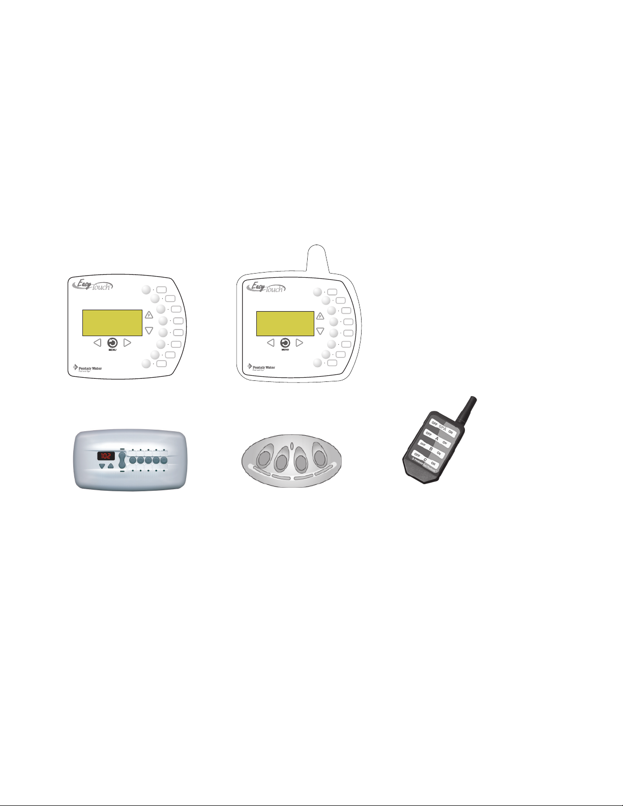
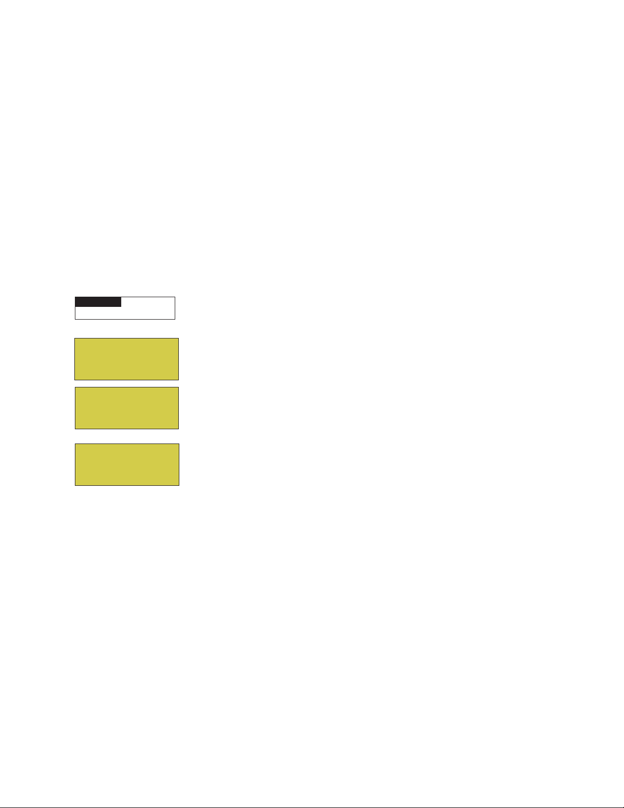
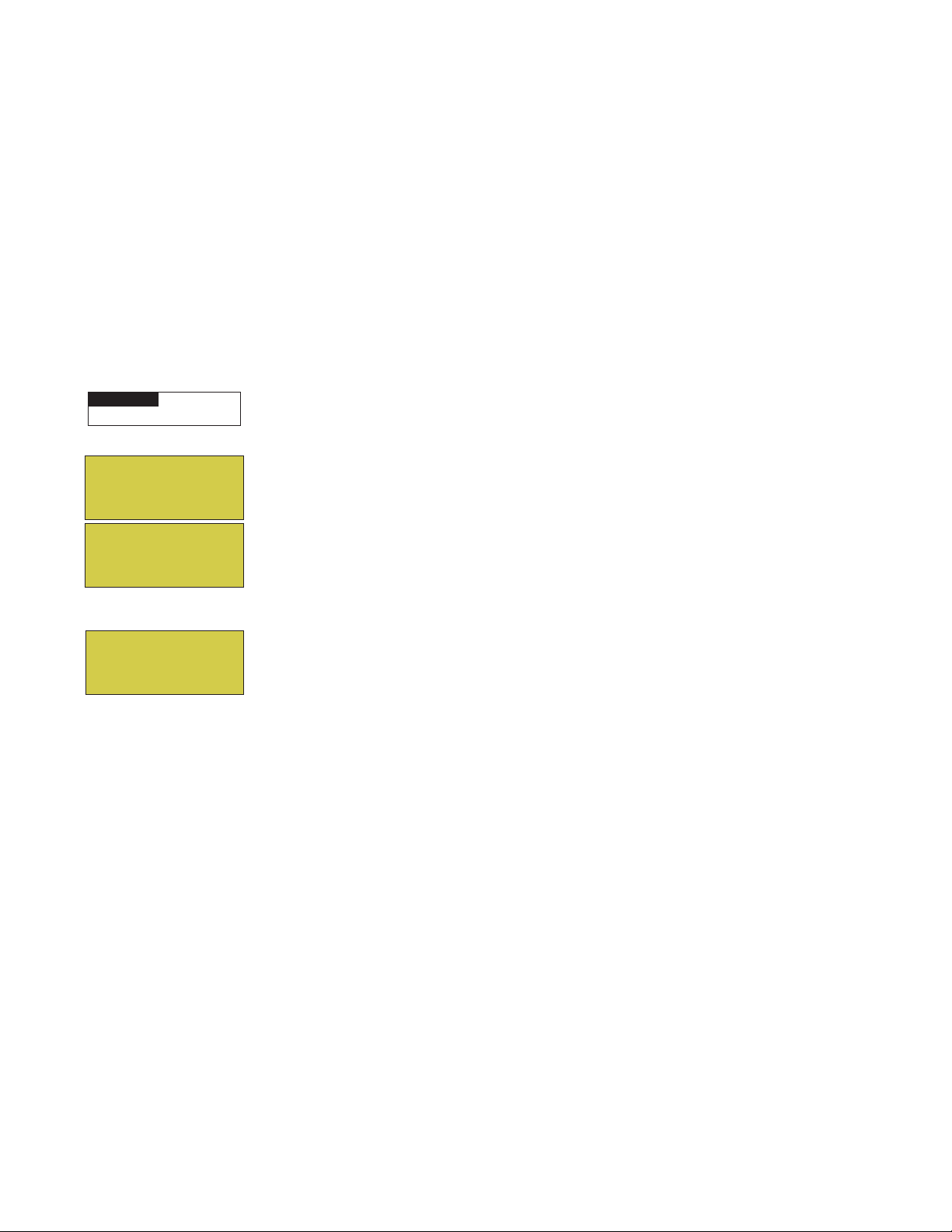
Accessory Equipment
POWER ON
EasyTouch 8 Indoor Control
Panel Kit (P/N 520549)
iS10 Spa-Side
Remote Controller (P/N 520149)
EasyTouch Wireless Control Panel
(8 circuit) Kit (P/N 520547)
iS4 Spa-Side Remote
Controller (P/N 520094)
QuickTouch® wireless remote controller
Kit (P/N 520148)
EasyTouch Accessories (continued)
EasyTouch Indoor Control Panel, 8 Circuits (P/N 520549)
EasyTouch Wireless Control Panel, 8 circuits (P/N 520547)
iS4 Four-Function Spa-Side remote, 150 ft. cable (P/N 520094)
iS10 Ten-Function Spa-Side remote, 150 ft. cable (P/N 520149)
QuickTouch four-function wireless remote kit with transceiver assembly (P/N 520148)
IntelliChlor Acid Cleaning Kit (P/N 520670)
IntelliChlor Spacer pass-through cell for new pool start-up (P/N 520588)
Technical Support
Sanford, North Carolina (8 A.M. to 5 P.M.)
Phone: (800) 831-7133 - Fax: (919) 566-8920
Moorpark, California (8 A.M. to 5 P.M.)
Phone: (800) 831-7133 - Fax: (805) 553-5515
visit www.pentairpool.com and www.staritepool.com
Compool/EasyTouch Pool and Spa Control System Upgrade Installation and User’s Guide
Page 9
Section 1
Overview
Compool® EasyTouch® Pool and Spa Control System Upgrade Overview
Welcome to the Compool EasyTouch upgrade Pool and Spa Control system − The next generation in
automatic control systems. Your Compool EasyTouch upgrade system opens up a wide range of automation
features. Your EasyTouch eight auxiliary system allows you to automatically control all of your spa and pool
daily operations. Pool and spa service operations can be manually controlled from the EasyTouch outdoor
control panel located at the pool equipment pad. Also available is the optional Indoor Control Panel and
Wireless Control Panel which allows automatic control of pool and spa operations from inside your home or
outside around your pool area.
The EasyTouch eight auxiliary circuit system is factory configured to operate as a “shared” equipment system
or it can be configured as a “single body” system (see page 64). For EasyTouch menu settings, see page 14.
The EasyTouch eight auxiliary system can control high voltage (120 VAC / 240 VAC) equipment, automatic
valve actuators, pumps, lighting, a conventional heater or a solar heating system and the optional IntelliChlor
salt chlorine generator.
Compool upgrade systems
1
The following Compool systems can be upgraded to the Compool/EasyTouch system: Compool CP3xxx
models (see page 66 and 67), also Compool TimeMaster, CP/LX100, CP1000, CP2000 and CP3000 models.
Note: To upgrade Compool TimeMaster, CP/LX100, CP1000, CP2000 models requires Compool/
EasyTouch control panel upgrade kit with transformer P/N 521247). Otherwise CP3xxx systems
require P/N 521107. For Compool/EasyTouch Control Panel with or without Transformer Kit installation
instructions, see page 65).
Operating EasyTouch
The EasyTouch system is designed to automatically control your pool and spa equipment, lights and other
optional equipment. However, you can also manually control all EasyTouch system operations from the outdoor
control panel. Using the “Mode” button, the system can be switched from “Auto” mode (normal operating
mode) to “Service” mode for manual operation and service purposes. Using the outdoor control panel buttons
you can manually override any automatic settings. If required, the EasyTouch outdoor control panel can be
password protected. To access a password protected control panel, the correct four digit password must be
entered before access is granted (see page 49).
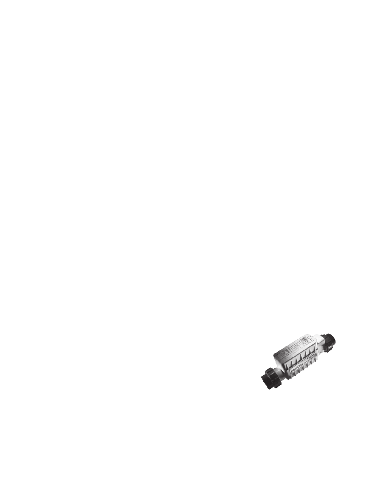
IntelliChlor® Electronic Chlorine Generator
The optional IntelliChlor salt chlorination system allows the EasyTouch
system to automatically control water sanitization by using a low
concentration of salt (sodium chloride) in the pool and spa water. The
IntelliChlor is enabled from the “IntelliChlor” Settings menu (see page 35).
IntelliChlor automatically converts the salt into free chlorine which eliminates
bacteria and algae in the pool and spa water. The chlorine will then revert
back to sodium chloride after killing the bacteria. The outcome of this
continuous cycle, practically eliminates the need to use sanitizing chemicals in
the pool/spa water. When the pool and spa water is replenished due to
backwashing or draining, more salt may need to be added to the pool/spa water. IntelliChlor model IC20 (P/N
520554/520556) is designed for swimming pools up to 20,000 U.S. gallons (75,000 liters). Model IC40 (P/N
520555/520556) is designed for swimming pools up to 40,000 U.S. gallons (151,000 liters). IC60 Cell (P/N
521105): Designed for pools up to 60,000 U.S. gallons (227,124 liters). The pool chlorination amounts may
vary depending on number of pool occupants, temperature, environment conditions, rainfall and other elements
that might affect the pool water.
IntelliChlor Electronic
Chlorine Generator
Compool/EasyTouch Pool and Spa Control System Upgrade Installation and User’s Guide
Page 10
2
Upgrade
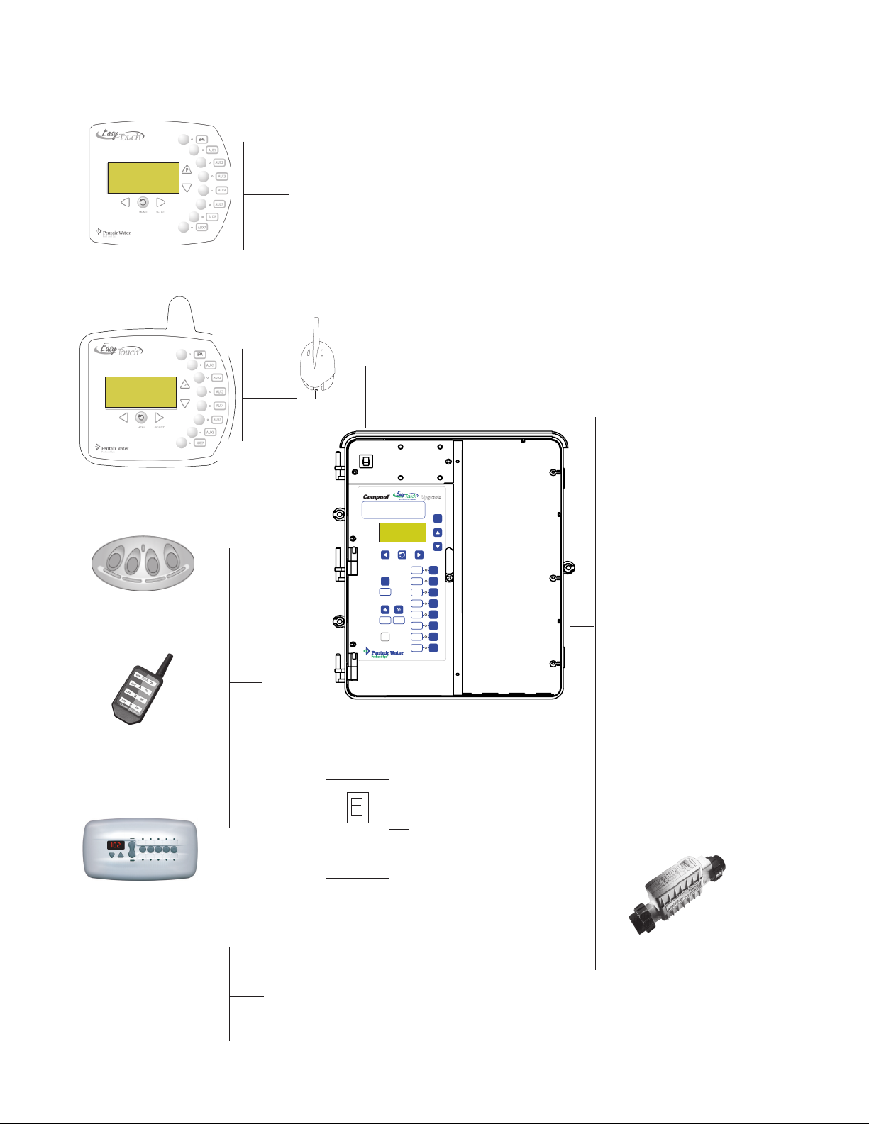
Compool EasyTouch Upgrade System Overview
Connects to
Compool/EasyTouch Upgrade motherboard via
RJ12 Adapter or 4-position screw terminal
EasyTouch Indoor
Control Panel (P/N 520549)
(Optional)
Low Voltage (DC)
circuit breakers
EasyTouch Wireless
Control Panel (8 circuit)
(P/N 520547) (Optional)
iS4 Spa-Side
Remote (P/N 520094)
(Optional)
MODES OF OPERATION
Auto:
Indoor control panel and other remote devices operate system.
Service:
Service buttons on this panel operate system.
Other remote devices are disabled.
Time Out:
Service buttons on this panel operate equipment for
three hours, then settings return to Auto mode.
AUTO HEATER
SPA 95 F / 100 F
AIR 70 F
MON 09:30 AM
MENU SELECT
Pool
Spa
Fill (Spillway)
V
Drain
VALVES
HEATER SOLAR
Reset
MODE
FILTER
F
PUMP
AUX 1
1
AUX 2
2
AUX 3
3
AUX 4
4
AUX 5
5
AUX 6
6
AUX 7
7
• Pumps
Filter, Cleaner, Spa Jet -
1.5 HP 120 VAC
3 HP 277 VAC
20 FLA/120 LRA,120 VAC
17 FLA/102 LRA, 277 VAC
• Pool/Spa Lights
1.5 KW 120 VAC Tungsten
4.8 KW 240 VAC Tungsten
20 AMP, 277 VAC Ballast
• Pool/Spa Valve
Suction and return.
24 VAC valve actuator,
shared equipment only
Compool Power Center
QuickTouch® (QT4)
(shown without subpanel)
wireless remote
Controller
(P/N 520148)
(Optional)
iS10 Spa-Side
Remote (P/N 520149)
Main Power GFCI Panel 240 VAC 50
AMP (40 AMP recommended 8 AWG)
(Optional)
Temperature Sensors
(Water, Air and
Solar optional)
Electric Heater -
Connects to plug J19 on
motherboard
Compool/EasyTouch Pool and Spa Control System Upgrade Installation and User’s Guide
• Auxiliary Valves
(Qty. 2) A and B
• Heater
Gas or electric
• Relays
20 AMP, 2 HP, 240 VAC
30 AMP, 3 HP, 240 VAC
optional
Optional equipment
• IntelliChlor Salt Chlorine
Generator (SCG)
• IC20 P/N 520554/520556
• IC40 P/N 520555/520556
• CIC60 P/N 521105
(see page 26)
Page 11
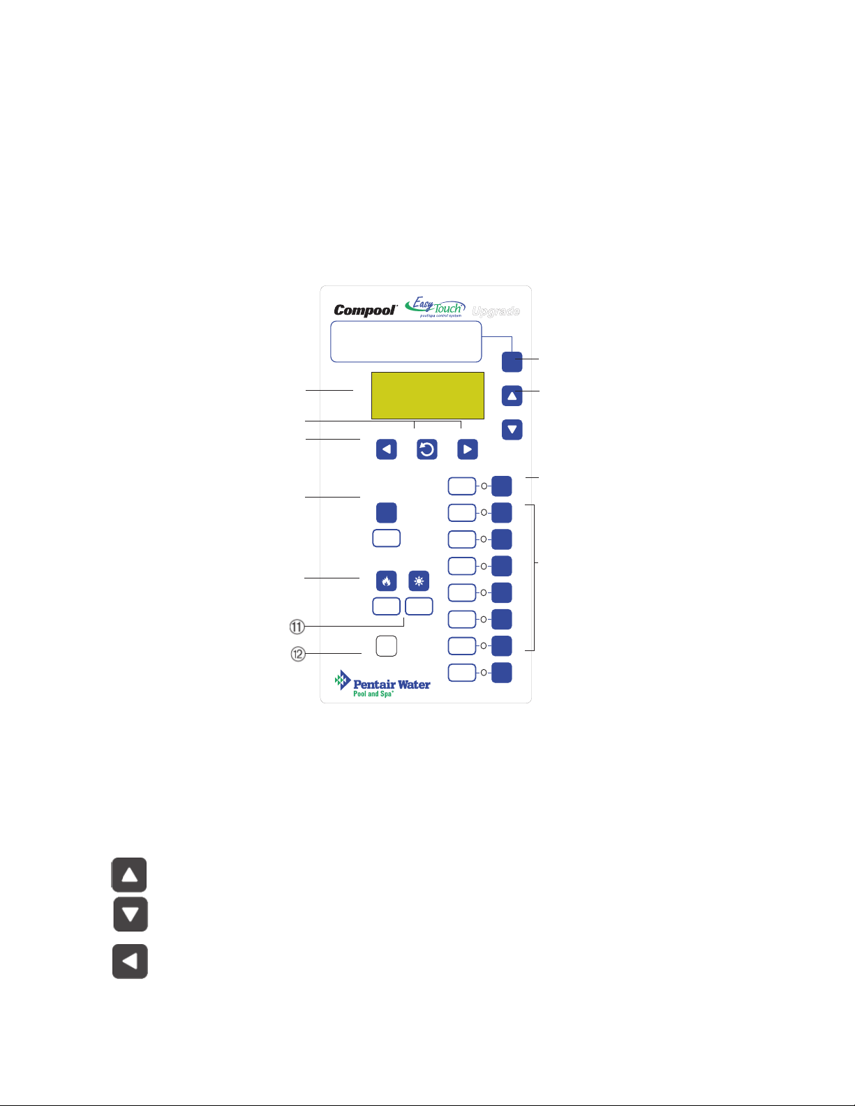
Compool EasyTouch Upgrade Control Panel
Your EasyTouch upgrade system can fully automate your pool, spa functions and any auxiliary circuits
(additional pumps and lighting) from the EasyTouch upgrade outdoor control panel or from the optional
EasyTouch indoor control panel and EasyTouch wireless control panel. The EasyTouch menu features let you
create customized schedules for your pool and spa equipment, heat temperatures, and chlorination settings to
switch on and off at a set day and time. Scheduled automatic operations can be performed at either the
outdoor control panel, the optional indoor control panel and wireless control panel. For maintenance and
service purposes, the outdoor control panel button allows manual control of all pool and spa operations. For
menu options, refer to “EasyTouch Menus,” on page 14. The following describes the outdoor control panel
buttons, and LED indicators.
MODES OF OPERATION
Auto:
Indoor control panel and other remote devices operate system.
Service:
Service buttons on this panel operate system.
Other remote devices are disabled.
Time Out:
Service buttons on this panel operate equipment for
➀
three hours, then settings return to Auto mode.
AUTO HEA TER
SPA 95 F / 100 F
AIR 70 F
MON 09:30 AM
MODE
➆
➁
➃➄
➂
MENU SELECT
➅
F
1
2
➇
V
VALVES
Pool
Spa
Fill (Spillway)
Drain
FILTER
PUMP
AUX 1
AUX 2
3
➉
HEATER SOLAR
Reset
AUX 3
AUX 4
AUX 5
AUX 6
AUX 7
➈
3
4
5
6
7
Compool/EasyTouch Upgrade Outdoor Control Panel
Comppol/EasyTouch Upgrade Controls and Buttons
Liquid Crystal Display (LCD): The main system display consists of a 16 x 4 alphanumeric character
➀
LCD with LED backlighting for easy viewing of the menu items and status messages. If necessary,
press the Menu button twice to refresh the display.
➁
➂
Up/Down buttons: Use the Up and Down buttons to scroll through the main menu items and to
adjust or change settings. Use these buttons after pressing the Menu button to access the main menu
items. While editing settings, press and hold the Up or Down button to fast forward or fast reverse
through settings and values.
Left button: When in pool or spa mode use the Left and Right button to adjust the temperature level.
Press the Left button to lower the set point water temperature. Press the Filter Pump (F) button to
display the current water temperature. Use the Left button to scroll through sub-menu selections,
setting and values. While editing settings, press and hold the Left button to fast reverse through
settings and values.
Compool/EasyTouch Pool and Spa Control System Upgrade Installation and User’s Guide
Page 12

4
Controls and buttons (Continued)
➃
➄
➅
MENU
SELECT
Menu/back button: Use this button to access, save and exit from a current menu or sub-menu
settings. Also, while in a menu or sub-menu items, use this button to go back to a previous menu
level or item. If no menu activity is detected after five minutes, the main screen is displayed. All
menu settings are permanently saved and retained in the control panel even after power is removed
from the control panel. Control panel buttons are disabled while in the menu mode.
Right button/SELECT: When in pool or spa mode use the Left and Right button to adjust the
temperature level. Press the Right button to raise the set point water temperature. Press the Filter
Pump (F) button to display the current water temperature. Use the Right button to select a sub-menu
item for editing. After pressing the Menu button to access the main menu items, use the Right button
to select the menu item and access the sub-menu items for adjustment. While editing a settings,
press and hold the Right button to fast forward through settings and values.
Filter Pump (F) button/LED: Switches a single speed filter pump on and off in “Pool” or “Spa”
mode. Press the Valves (V) button to toggle between “Pool” and “Spa” mode and rotate valves. If
“Heater” is enabled in the “Heat” menu (see page 25), pressing the Filter Pump button will also
enable the selected heat source (Heater/Solar LED on). The default time before the filter pump will
switch off is 12 hours. This button operates in “Auto” or “Service” mode.
Single-Speed Filter Pump: If the pump is currently off, press the Filter Pump button (LED on) to
switch the pump on. Press the Filter Pump button again to switch the pump off. However, if the
heater is operating, and a delay is enabled for valves, this allows the heater to cool down (heater
cool-down), then when you press the F button to switch off the pump, only the heater will turn off,
then the filter pump will automatically switch off after 10 minutes to allow the heater to cool down.
Pentair Water Pool and Spa® heaters do not require a cool down time. To override the “heater cooldown,” press the Filter Pump button again to switch off the pump.
➆
Two-Speed Filter Pump: Press the Filter Pump button (LED on) to switch the two-speed pump on
in high speed. If you switch the pump off to low speed shortly after switching it to high speed, the
filter pump will automatically remain in high speed for a few minutes before switching back to low
speed to allow the pump to prime and establish normal water flow. In order to use the “2-Speed
Pump” menu assignments (see page 42), the 2-Speed relay option must be installed in the
EasyTouch Load Center.
Freeze Protection: This function protects the pool, plumbing, and equipment against freeze damage.
If the outside air temperature sensor falls below
36° F, “Freeze Protection” is activated and the Filter Pump relay is switched on to circulate the pool
water. To enable freeze protection for a circuit, see “Settings Menu: Circuit Function, ” on page 39.
Mode button: Use this button for service purposes to manually control the EasyTouch system. Press
this button once activate “Service” mode, to allow AUX circuit buttons, Filter Pump, Valves, Heater
and Solar buttons to be operated manually. Press the button a second time to enable “Timeout”
mode. This mode is similar to “Service” mode except that the system will automatically return to
normal operation (Auto) after three hours. Press the button a third time to return the system to
“AUTO” mode. The current operating status is shown in the LCD display. The menu buttons,
remote controllers, and menu scheduled operations are disabled (except for switching off equipment
manually for emergencies) while the system is in “Service” mode.
Auto: In Auto (automatic) mode the system is in normal operating mode and is controlled by the
main control panel LCD menu features.
Service: Use this mode to service pool equipment and to operate equipment manually.
Timeout: Same functionality as “Service” mode, except that the system will automatically return to
normal operation (Auto) after three hours.
Compool/EasyTouch Pool and Spa Control System Upgrade Installation and User’s Guide
Page 13
Controls and buttons (Continued)
5
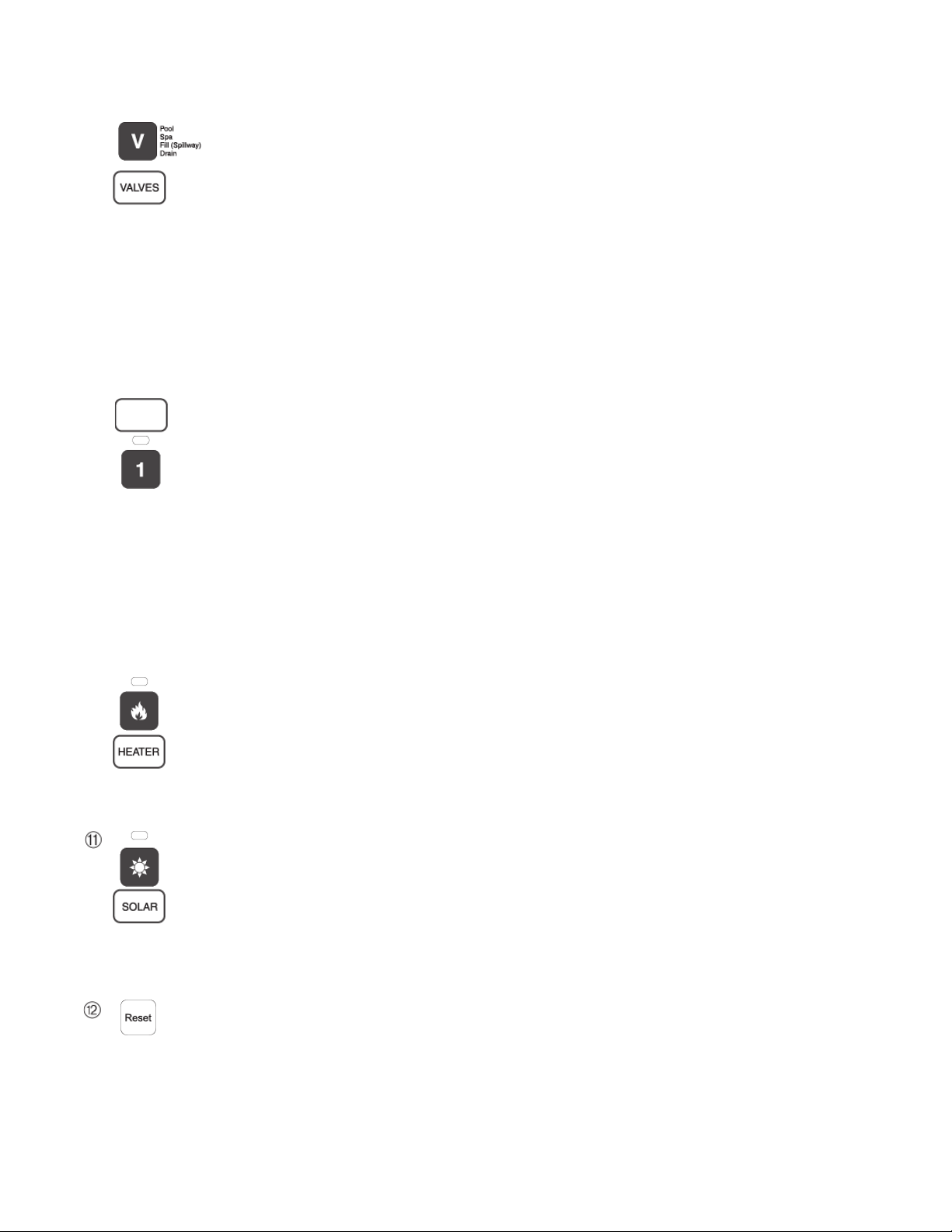
➇
➈
Valves (V) - (Pool/Spa/Fill (Spillway)/Drain) button: When in normal operating mode, the
Valves (V) button is in “Pool” mode. In this mode the valves are automatically rotated so that
only the pool water is circulated through the system and the filter pump is activated. Pressing this
button once enables “Spa” mode and activates the filter pump to circulate only spa water
through the system. “Fill/Spillway” and “Drain” mode can only be used while in “Service” mode
(See Mode button for details). “Fill/Spillway” and “Drain” mode are used when cleaning the spa.
Pressing the Valves (V) button again returns the system to “Pool” mode. Note that the filter
pump will switch off while the pool/spa valves are rotating into position. The current operating
mode is shown in the LCD display. Note: The Valves button (Pool, Spa, Fill (Spillway),
Drain) button has no function in “Pool only” or “Spa only” systems. For an EasyTouch
single body system, “Pool” and “Spa” modes are Lo- Temp (Pool) and Hi-Temp (Spa)
temperature controls. For more information, see “Hi-Temp/Lo-Temp Controls for Single
Body Systems,” page 37.
Aux 1 - 7 buttons/LEDs: Auxiliary output circuit buttons operate the pool and spa system valves,
lights and other equipment. These auxiliary circuits are assigned in the “Circuit Function” menu, see
page 39 for details. There are seven auxiliary circuits (AUX 1- 7) on Compool/EasyTouch outdoor
control panel. The Solar button can also be used for an “extra” auxiliary circuit if the Solar circuit is
not being for solar equipment. Labels can be affixed next to each auxiliary button to identify the
circuit function. Labels can be affixed over each auxiliary button to identify the circuit function.
When an auxiliary circuit is activated or the button is pressed, the LED is on. Pressing an auxiliary
circuit button will activate the corresponding circuit in either “Auto” or “Service” mode. When a
circuit relay is switched on manually, it remains on until either you switch it off manually, or the next
time the relay is scheduled to be switched off. For example, if the filter pump is scheduled to
automatically run from 9:00 AM to 5:00 PM daily then the filter pump is switched on manually at
9:00 PM, it will run continuously until the next day at 6:00 PM then switch off. The schedule will
then continue from then on.
➉
Heater (Flame) button/LED: This button is only used in “Service” mode for manual heat on and off
control. The Heater LED will be on if “Heater” is enabled in the “Heat” menu setting (see page 25).
Switching the heater on automatically controls the output between a “forced off” state and a normal
automatic thermostatic control operating state. The heater will continue heating the water until the
heater’s current highest set point temperature triggers the heater sensor (approximately 104° F).
Note that the Heater button does not activate the pump. Do not activate the heater without running
the pump. The heater will not run if water flow is not detected.
Solar (Sun) button/LED and (Aux Extra): In solar mode this button is only used in “Service” mode
for manual solar heat on and off control. The Solar LED will be on if “Solar” is enabled in the
“Heat” menu setting. Solar must also be enabled in the “Solar” menu. Use the Solar button to
manually switch the heater control output between a “forced off” state and a normal automatic
thermostatic control operating state. When this button is pressed the solar relay is switched on to
activate a booster pump if installed and activates valves to rotate to divert water through solar
heating panels. If solar equipment is not being used, this button can also be used to switch the AUX
EXTRA circuit on and off.
Reset button: Press this button to reinitialize the Compool/EasyTouch outdoor control panel.
Compool/EasyTouch Pool and Spa Control System Upgrade Installation and User’s Guide
Page 14
6
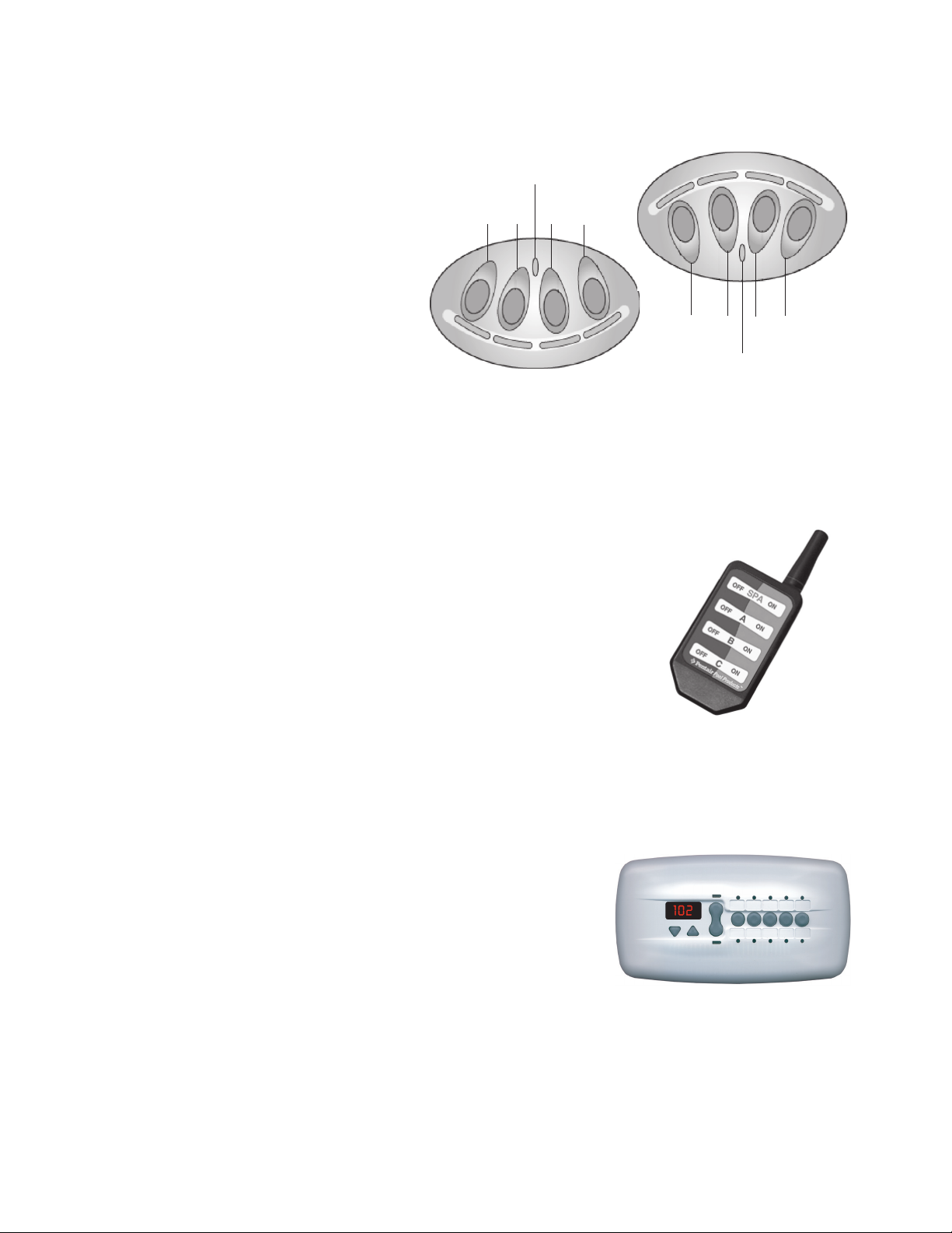
iS4 Spa-Side Remote Controller (Optional)
The iS4 Spa-Side remote controller is a doubleinsulated, waterproof device that is UL (1563)
listed for installation at the water’s edge.
Pentair recommends that the iS4 always be
installed above the water line of the spa wall, or
in the deck within arm’s reach of a spa
occupant. The iS4 provides remote switching of
up to four control circuits from the spa location.
It is typically used for activating spa circulation
and any three auxiliary pieces of equipment
(such as lights, jet pump, air blower, etc.). The
red status LED indicator glows steady when in
Spa mode and flashes while the spa is heating.
For more about assigning circuits to the iS4
buttons, refer to “Settings Menu: iS4 Spa-Side
Remote controller,” on page 44. The iS4 two
installation choices are shown below:
Red power LED
1
iS4 Spa-Side Remote
Controller (Wall or tile
mount)
indicator
2
3
4
4
3
2
1
Red power
LED indicator
iS4 Spa-Side Remote
Controller (Deck
mount)
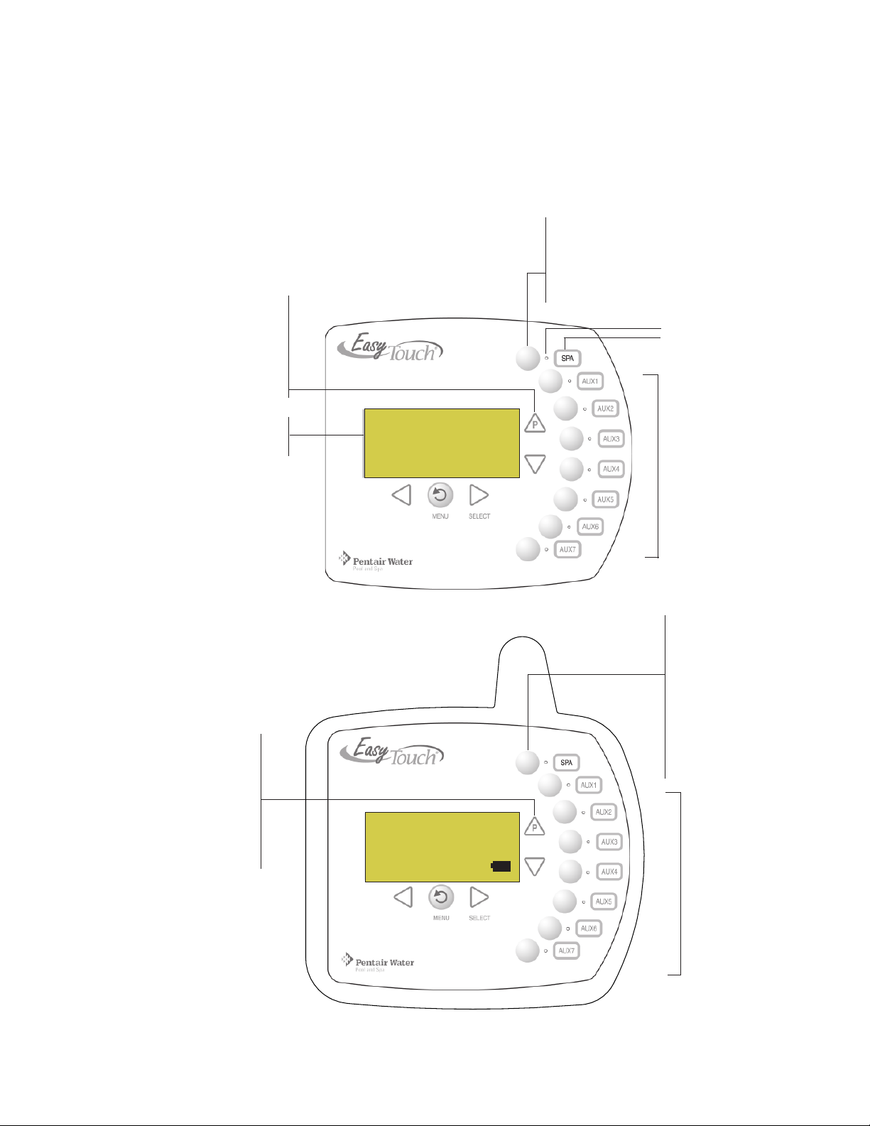
QuickTouch® QT4 Wireless Controller (Optional)
The QuickTouch QT4 wireless remote controller provides switching of up to
four circuits. You can use the QT4 wireless controller to activate the spa
circulation, and for operating three auxiliary pieces of equipment (such as lights,
jet pump, air blower, waterfall, etc.). Each of the four functions on the QT4
wireless controller has an on and an off button. For more about assigning
circuits to the QT4 buttons, refer to “Settings Menu: QuickTouch (QT4)
Wireless Remote,” on page 47.
IMPORTANT: The QT4 wireless controller may be used with wet hands,
but should never be submersed in water as this could damage the QT4. If
accidental submersion occurs, dry the QT4 out by removing battery cover
and removing battery. Position the QT4 so that water can drain out.
Reassemble when the QT4 is completely dry.
QuickTouch (QT4) Wireless
Remote Controller (P/N 520148)
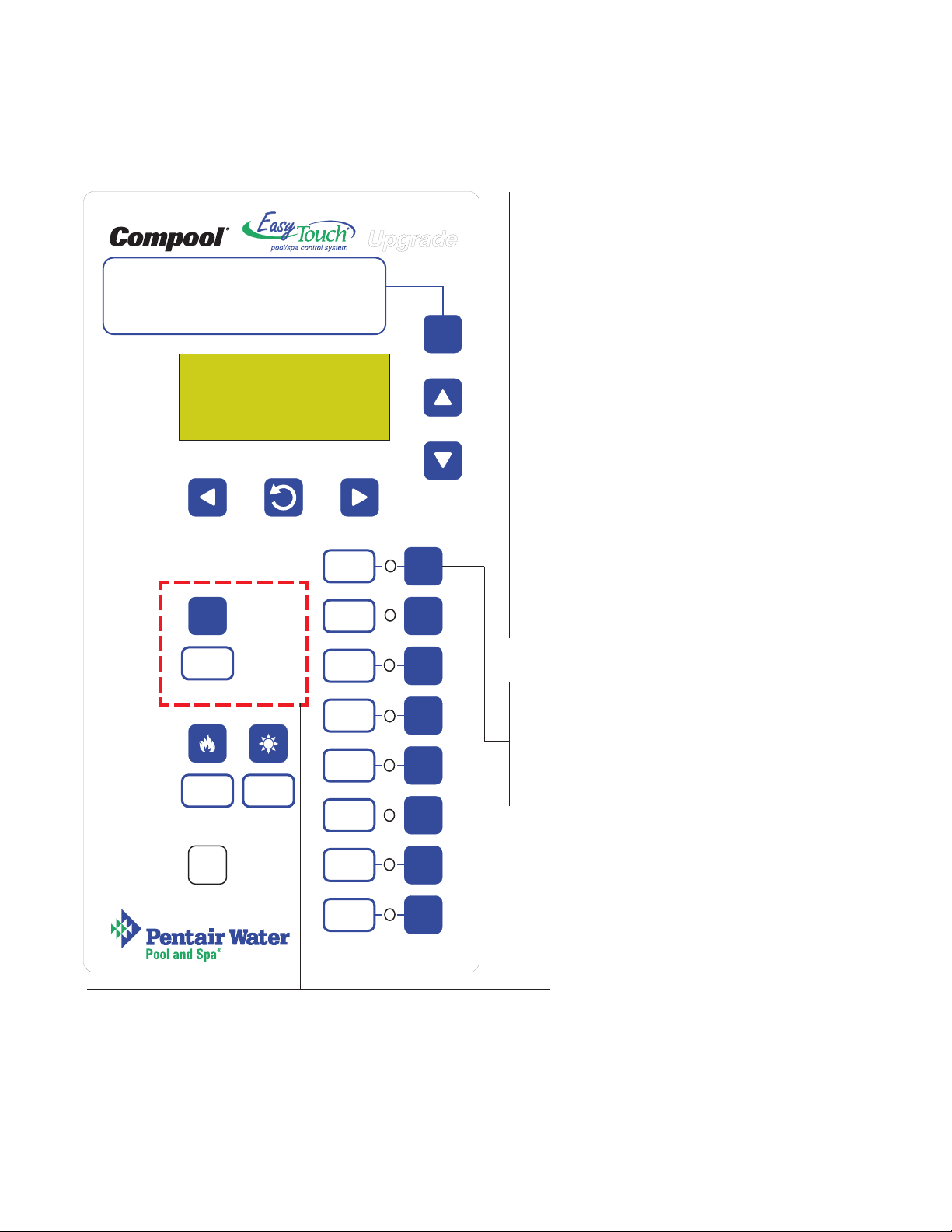
iS10 Spa-Side Remote Controller (Optional)
An iS10 Spa-Side remote controller can control up to ten functions
including a spa temperature adjustment. The iS10 Spa-Side remote
controller is listed UL (1563) for use with the EasyTouch systems at the
water’s edge. Five (5) in-line buttons control up to ten (10) system
functions numbered one through five from left to right. The middle
peanut-shaped button toggles between the top and bottom row of
buttons. The iS10 includes an LED display shows the current spa water
temperature. The spa temperature may be increased or decreased by
pressing the up or down arrow button located under the display. The
temperature display will blink while being changed. After setting the desired temperature, the display will return
to steady and show the actual temperature as it meets the set point. The temperature set by the iS10 is only
temporary. When the Spa mode is switched OFF, the temperature set at the EasyTouch control panel will
resume the next time the spa mode is activated (see “Man Heat” on page 48). The Spa Mode will automatically
turn off after 24 hours. For iS10 setup and configuration information, see page 45.
iS10 Spa Side Remote
Controller (P/N 520149)
Compool/EasyTouch Pool and Spa Control System Upgrade Installation and User’s Guide
Page 15
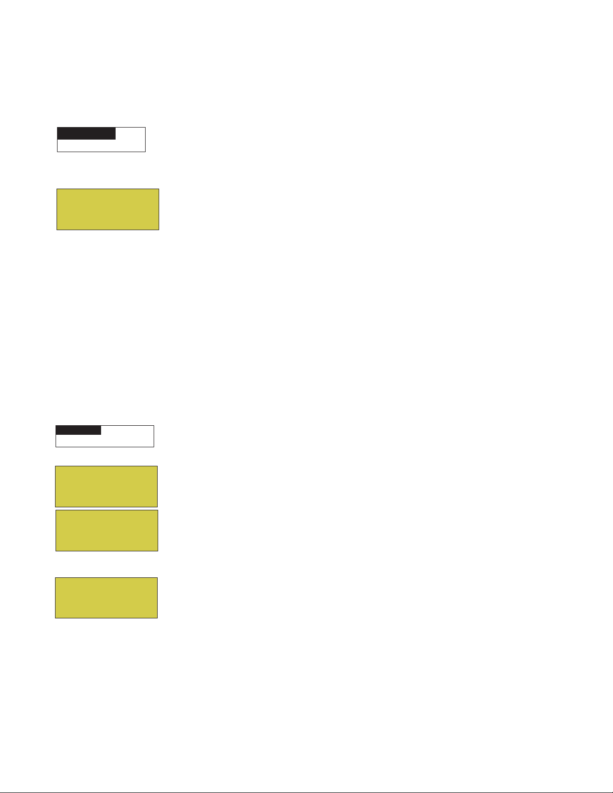
EasyTouch Indoor and Wireless Control Panel (Optional)
The EasyTouch Wireless or the Indoor Control Panel allows you to control your pool and spa daily operations
from around your pool area or inside your home. Use the “P” (Pool) and “Spa” (Pool) buttons to heat and
filter your pool and spa. The Indoor Control Panel connects to the EasyTouch motherboard in the load center.
For more information refer to the EasyTouch Indoor Control Panel User’s Guide (P/N 520616) and the
EasyTouch Wireless Control Panel User’s Guide (P/N 520688).
Spa (Hi-Temp) Button: Switches the filter
pump on, rotates valve actuator (to isolate spa
water from pool water), and switches the
heater on. Hi-Temp (EasyTouch single body
system) sets the high temperature settings for
Pool (Lo-Temp) Button: Switches
the filter pump on, rotates valve
actuator (to isolate pool water from
spa water), and switches heater on.
Lo-Temp (EasyTouch single body
system) sets the low temperature
settings for the pool (see page 37)
the spa.
Circuit LED
Circuit name label
7
For details about the
control panel LCD status
messages, see page 8
Pool (Lo-Temp) Button:
Switches the filter pump on,
rotates valve actuator (to
isolate pool water from spa
water), and switches heater on.
Lo-Temp (EasyTouch single
body system) sets the low
temperature settings for the
pool.
AUTO HEATER
SPA 100°F / 95°F
AIR 70°F
MON 09:30 AM
EasyTouch indoor control panel - (P/N 520549)
AUTO HEATER
SPA 95°F / 100°F
AIR 70°F
MON 09:30 AM
POWER ON
Seven user defined
auxiliary circuits.
Buttons switch the
assigned circuit function
on/off (12 hour time-out).
Down arrow button can
also be used for an
“extra” auxiliary circuit if
solar equipment is not
being used
Spa (Hi-Temp) Button:
Switches the filter pump
on, rotates valve
actuator (to isolate spa
water from pool water),
and switches the heater
on. Hi-Temp (EasyTouch
single body system) sets
the high temperature
settings for the
spa.
Seven user defined
auxiliary circuits.
Buttons switch the
assigned circuit
function on/off
(12 hour time-out)
Down arrow button
can also be used for
an “extra” auxiliary
circuit if solar
equipment is not
being used
EasyTouch wireless control panel - (P/N 520547)
Compool/EasyTouch Pool and Spa Control System Upgrade Installation and User’s Guide
Page 16
8
Compool/EasyTouch Upgrade Outdoor Control Panel Operating Modes
The Compool/EasyTouch system can run in automatic mode or manual mode. Use the “Mode” button to switch
the system from “Auto” mode (normal operating mode) to “Service” for manual operation and service purposes.
Before operating EasyTouch, familiarize yourself with the LCD status messages and operating buttons.
AUTO (Automatic): The system is in normal
operating mode. Scheduled programs will run
automatically.
MODES OF OPERATION
Auto:
Indoor control panel and other remote devices operate system.
Service:
Other remote devices are disabled.
Time Out:
three hours, then settings return to Auto mode.
Service buttons on this panel operate system.
Service buttons on this panel operate equipment for
AUTO HEATER
SPA 95 F / 100 F
AIR 70 F
MON 09:30 AM
MENU SELECT
Pool
Spa
Fill (Spillway)
V
Drain
FILTER
PUMP
AUX 1
MODE
F
1
HEATER: Displays the heat source (Off, Heater,
Solar Prf., Solar) as specified in the Heater menu
settings (see page 25). When the Filter Pump (F)
button is pressed in “Pool” or “Spa” mode, and heat
source is enabled (Heater button LED on).
POOL (SPA): Indicates that the Valves (V) button is
in “Pool” or “Spa” mode and the Filter Pump (F)
button has been pressed to switch on the filter
pump. If this display line is blank, it indicates no
spa or pool function is active. For an EasyTouch
single body system, Hi-Temp (Spa) / Lo-Temp (Pool)
sets the temperature settings (see page 37)
95° F / 100° F: Displays the actual spa or pool
water temperature (95° F) and the set point temperature (100° F) as set in the “Heater” menu.
AIR: Displays the actual outside air temperature
(70° F) as read by the air sensor located near the
EasyTouch Load Center.
Date and Time: Displays the EasyTouch system
day and time as specified in the “Clock” menu
settings (see page 31).
VALVES
AUX 2
2
Filter Pump button:
AUX 3
3
For spa operations, press the Valves (V) button to
rotate valves into “Spa” mode, then press the
Filter (F) button to activate the filter pump. Press
the Valves button to toggle to “Pool” mode. The
Heater button LED will be on if a heat source is
enabled in the Heat menu.
HEATER SOLAR
Reset
AUX 4
AUX 5
AUX 6
AUX 7
4
5
6
7
Valves (V) button: When in normal operating mode, the system is in
“Pool” mode so that only the pool water is circulated through the
system. Press the Valves button to enable “Spa” mode and to rotate
valves and activate the Filter pump (Filter Pump LED on)
automatically so that only the spa water is circulated through the
system. Note that the filter pump will switch off while the pool/spa
valves are rotating into position. “Fill/Spillway” and “Drain” modes are
used only in “Service” mode.
Compool/EasyTouch Pool and Spa Control System Upgrade Installation and User’s Guide
Page 17

Quick Start - Spa and Pool Operations (Shared Equipment)
Getting There
MENU HEAT
▲
The following describes how to adjust heat temperature for the spa and pool water, schedule a daily run time
for the pool/spa filter pump and control lights for shared equipment.
Heat your spa or pool
9
AUTO HEATER
SPA 95°F / 100°F
AIR 70°F
MON 09:30 AM
First enable the heat source (see “Adjust your spa heat settings” below) then press
the Valves (V) button to enable “Spa” mode, and press the Filter Pump button to
activate the filter pump. When in normal operating mode, the Valves (V) button is in
“Pool” mode which turns valves and activates the filter pump automatically so that
only the pool water is circulated through the system. Press the button to enable “Spa”
mode and activate the Filter pump to circulate only spa water through the system. In
the main screen shown on left, 95°F is the current temperature and 100° F is set point
temperature. By default, the setting “Man Heat’ is set to “On” (see page 48) which
allows the spa to begin to heat whenever it is manually switched on.
From the Indoor or wireless control panel (option): First enable the heat source
in the Heat menu (see “Heat Menu,” on page 25). Press the Spa button (top button)
to switch the filter pump on, rotate the valve actuator (to isolate spa water from pool
water), and switch the heater on. Press the Pool button to switch the filter pump on,
rotate the valve actuator (to isolate pool water from spa water), and switch the heater
on. For Pool and Spa button location, see page 7.
Adjust your spa or pool heat settings
From the “Heat” menu (MENU > HEAT > POOL TEMP/SRC OR SPA TEMP/SCR) you can select the heat
source and set the water temperature. The spa or pool water will heat to the settings specified. The
EasyTouch system allows for solar and conventional heaters. The EasyTouch will use the heating source that
is selected. The heat source selections are:
•
OFF - No heating even though pump and other circuits may be operating.
• HEATER - Gas heater only.
• SOLAR - Solar heating system to be the only heat source. In order to display “Solar Only” as a heat
option in the “Heat” menu, you must first enable solar in the Settings > Solar menu,
(see page 42).
• SOLAR PREF. (Solar Preferred) - Used if solar and gas heating are combined and you want to use
solar heating only when it is most effective. In order to display “Solar Preferred” as a heat option in
the “Heat” menu, you must first enable solar in the Settings > Solar menu (see page 42).
• Heat Pump (ThermalFLo): If a heat pump is being used (ThermalFlo), enable the ThermalFlo and
heating setting from the Settings > ThermalFlo > Settings menu options (see page 36).
To set the spa temperature set point and select the heat source:
Right button: Select spa temperature and heat source.
POOL Temp/Src
SPA Temp/Src
SPA
Set Temp: 85° F
Heat: Heater
Up/Down button: Adjust the spa water temperature.
(from 40° F to 104° F or 4° C to 40° C)
Right or Left button: Select Heat source options.
Up/Down: Set the Heat option: Off, Heater, Solar, or Solar Preferred.
Press the Menu button to save the settings and to return to the Heat menu or press
the button again to return to the main screen. Note: Select “
POOL Temp/Src” to
adjust the pool temperature.
Compool/EasyTouch Pool and Spa Control System Upgrade Installation and User’s Guide
Page 18
10
Switch on lights manually and synchronize light colors
From the Lights screen you can manually switch all lights on or off, and synchronize colored lights. Up to 12
lights can be controlled. For more information about setting up lights, including IntelliBrite® LED lights and
MagicStream® laminars, refer to “Lights Menu” on page 20.
Getting There
Menu Lights All On
▲
▲
To manually switch on all lights and synchronize light colors:
Press the Up/Down button to select All On or All Off. Use the Sync feature with
Modes
Colors
All On
All Off
any combination of up to 12 SAm
MagicStream laminars to synchronize their colors before switching the lights on.
®
, SAL®, IntelliBrite, FIBERworks® lights and
Press the Menu button to save the settings and to return to the main menu items or
press the button again to return to the main screen.
Using the Once Only timer feature
The Schedules “Once Only” timer feature lets you to automatically switch equipment on for one time. This
feature allows you to program a circuit to turn on at a particular time on a onetime basis. For example, if you
wanted the spa to be heated when you arrive home, you could program the heater to switch on at a specific
time and after you have finished using the spa you can switch the heater off manually. After the program has
run, it is automatically erased. Unlike using the regular “Schedule” program, the “Once Only” program does
not repeat. The circuit must be turned off manually or wait for the 12 hour automatic shut-off. However, you
could also reset the 12 hour factory shut-off by entering an “Egg Timer” count down program to extend past
the default 12 hours shut-off.
To schedule a specific time to turn on the spa or pool heat using the “Once Only “ feature:
Getting There
MENU ▼ SCHEDULES SPA (POOL)
▲
Right button: Select the Spa circuit.
Right button: Select Mode if there are existing programs. Skip this step to create a
new program.
SPA 0
POOL 0
AUX 1 0
AUX 2 0
SPA 0/0
Mode: None (New)
Up/Down button: Select New to create a new program.
Right button: To create a new program and enter the “Mode” settings.
Up/Down button: 1/1 indicates that this circuit has one program. If there are existing
programs assigned to this circuit, use these buttons to view and select the existing
program settings.
Right button: To select the “Once Only” settings.
Right button: Select start time setting.
Up/Down and Right buttons: Set the start hour (A/P) and minutes. A (AM) and
P (PM) time is set when setting the start hour.
SPA 1/1
Mode: Once Only
08:00A
_
SM TWTFS
Right button: Select the day of the week to run the program.
Right button: Select which day to run the program then press the Up/Down button
to enable the bar on top of the letter. A bar on top of the letter indicates the day
selected to run the program.
Press the Menu button to save the settings and to return to the Schedules menu
options. Press the Menu button again to return to the main menu options or press
again to return to the main screen.
Compool/EasyTouch Pool and Spa Control System Upgrade Installation and User’s Guide
Page 19
Schedule start and stop times for equipment
MENU ▼ SCHEDULES SPA (POOL)
Getting There
▲
You can set timers (schedules) to automatically run equipment for pool filtration or turn on or off lights. Any
EasyTouch circuit can be set to switch on and off on every or any day of the week. Up to 12 total system
programs may be created for all circuits combined.
Program your Spa or Pool
You can use the “Schedule” feature to set the time and day(s) when to switch the filter pump on and rotate the
pool/spa valves into the “Pool” or “Spa” position. The heater will automatically heat the pool or spa water up
to the set point temperature as set in the “Heat” menu (see page 25). If the pool has a separate jet pump or
blower controlled by AUX 1 and/or AUX 2 , these need to be scheduled separately. If you don’t have enough
or you need to conserve auxiliary relay circuits, you can program up to eight (8) “Feature Circuits.” If a
feature circuit is scheduled, it must be turned on from the control panel “Feature Circuits” menu to allow the
schedule to run (see page 17).
Schedules
To create a schedule for your spa or pool:
11
SPA 0
POOL 0
AUX 1 0
AUX 2 0
SPA 0/0
Mode: None (New)
SPA 1/1
Mode: Schedule
08:00A - 05:00P
__ _ _
mt wtfs
s
Right button: Select the Spa or Pool circuit. You can also select any of the available
circuits. The generic circuit names are: Spa, Pool, Aux 1-7 and Aux Extra. Aux Extra
is only available if the Solar output (J17) plug on the EasyTouch motherboard is not
being used for solar equipment. Use the Solar button to switch the “extra” circuit on
and off (see page 5).
Right button: Select Mode if there are existing programs. Skip this step to create a
new program.
Up/Down button: Select New to create a new program.
Right button: To create a new program and enter the “Mode” settings.
Up/Down button: 1/1 indicates that this circuit has one program. If there are existing
programs assigned to this circuit, use these buttons to view and select the existing
program settings.
Right button: To select the “Schedule” settings.
Right button: Select start and stop time settings.
Up/Down and Right buttons: Set start and stop hour (A/P), minutes.
The A (AM) and P (PM) time is set when setting the start and stop hour.
Right button: Select the days of the week to run the program.
Right and Up/Down buttons: By default the program is set to run all the days of
the week. If you wish to edit which days to run the program, select the day of the
week, then press the Up/Down button to remove the bar from the top of the letter. A
bar on top of the letter indicates the day selected to run the program.
Press the Menu button to save the settings and to return to the Schedules menu
options. Press the button again to return to the main menu options or press again to
return to the main screen.
Compool/EasyTouch Pool and Spa Control System Upgrade Installation and User’s Guide
Page 20
12
Setting the Egg Timer Feature
The “Egg Timer” feature lets you manually switch on equipment and program the system to automatically
switch off after a specified time. You can set this timer feature for other equipment such as lighting, spa, or
spa jets. Equipment can be set to be on for one minute or 24 hours. The Egg Timer program is factory set to
switch off after 12 hours. You also have the option to use the “Don’t Stop” feature to run a circuit continuously
until manually switched off.
Please note that in the event of a power failure, the Egg Timer feature will not switch the circuit back on. Use
the “Service” mode button to turn the equipment back on. Refer to “Mode button,” page 4 for details.
Note: When running the filter pump continuously during a new pool start up, it is recommended to use
the “Service” mode, which will automatically restart the filter pump in the event of a power failure.
To set the Egg Timer feature:
Getting There
MENU ▼ SCHEDULES SPA (POOL)
SPA 0
POOL 0
AUX 1 0
AUX 2 0
SPA 0/0
Mode: None (New)
SPA 1/1
Mode: Egg Timer
Time: 05:00
▲
Right button: Select the Spa or Pool circuit. You can also select any of the available
circuits. The generic circuit names are: Spa, Pool, Aux 1-7, Feature 1-8 and Aux
Extra. Aux Extra is only available if the Solar output (J17) plug on the EasyTouch
motherboard is not being used for solar equipment. Use the Solar button to switch the
“extra” circuit on and off (see page 5).
Right button: Select Mode if there are existing programs. Skip this step to create a
new program.
Up/Down button: Select New to create a new program.
Right button: To create a new program and enter the “Mode” settings.
Up/Down button: 1/1 indicates that this circuit has one program. You create a total
of 12 programs. If there are existing programs assigned to this circuit, use these
buttons to view and select the existing program settings.
Right button: To select the “Egg Timer” settings.
Right button: Select the time settings.
Up/Down and Right buttons: Set the hour and minutes for the program to run. The
count down time can be set from 00:01 to 23:59 and Don’t Stop. The “Don’t Stop”
feature allows the circuit to run continuously until manually switched off.
Press the Menu button to save the settings and to return to the Schedules menu
options. Press the button again to return to the main menu options or press again to
return to the main screen.
Compool/EasyTouch Pool and Spa Control System Upgrade Installation and User’s Guide
Page 21

Section 2
Setting up Compool/EasyTouch Upgrade System
Setting up the Compool/EasyTouch Upgrade System for the First Time
Use the following steps to setup up the Compool EasyTouch Upgrade system for the first time.
1. Set the system date and time (page 31)
Set the current date and time.
2. Assign circuit names (pages 37)
Assign the generic default circuit names for output auxiliary equipment. Rename (if necessary) and assign
circuit names to the auxiliary (AUX 1, AUX 2) connections. Note the factory set auxiliary names correspond
to the plug-in location of the relay on the EasyTouch motherboard. Assign circuit names from the available of
circuit names. There are nearly 100 circuit names available (see page 38 for the complete list).
13
3. Creating custom names for auxiliary circuits (page 41)
If you cannot find a circuit name that fits your application you can create up to 10 additional customized
names that can be created before assigning circuit names.
4. Assign a “Circuit Function” to a “Circuit Name” (Page 39)
Assign “Circuit Functions” to circuits. From the Circuit Function” menu (page 39), you can assign special logic
to a circuit by selecting one of the available circuit functions. For the complete list of preset Circuit Functions
see page 40. If an auxiliary circuit (AUX) is assigned GENERIC (simple ON/OFF when the button is pushed)
then nothing needs to be done.
5. Configure valve actuators (controlled by AUX circuit) (page 41)
The EasyTouch system can drive two auxiliary valve actuators for applications such as solar heating and
water features. Assign which circuits that will activate valves A and B. Auxiliary valve actuators can be
controlled by any AUX circuit. Valve A is automatically assigned to solar if “Solar” is enabled in the “Solar”
menu.
6. Set up optional equipment, solar, two-speed pump (page 42)
Set up additional equipment such as solar, 2-speed pump, and optional equipment if required. Set up the control
panel to operate with the optional IntelliChlor chlorine generator (see page 35). To configure EasyTouch for
special equipment:
• Is solar heating available? Is solar being used for a heat pump?
• What circuits will turn 2-Speed pumps to High Speed?
• Cool-down cycle for the heater - Lets you set circuits that switch the filter pump to high speed.
• Do you want to delay turning off the filter pump for 10 minutes when the heater is turned off?
• Do you want the spa to heat whenever the Spa button is pressed?
Compool/EasyTouch Pool and Spa Control System Upgrade Installation and User’s Guide
Page 22
14
7. Configuring the heater system options (page 25)
Set the type of heat source being used (Heater, Solar, Solar Preferred).
8. Configure the iS4, iS10 spa-side remote, QuickTouch wireless remote buttons (page 44)
Assign circuits to the iS4, iS10 or QuickTouch remote buttons. Once you have checked that all buttons
operate properly, place labels on remote buttons.
9. Set the delays feature (page 43)
Enable the one time “delay” feature for the heater, 2-speed pump, and automatic pool cleaner.
10. Schedule on/off times for circuit (page 27 - 30)
Set times for automatic circuit activation. Up to 12 total programs can be created for all circuits combined.
One circuit can have up to a maximum of 9 programs (9/9), which leaves 3 programs that can be used by one
circuit or three separate circuits for a total of 12 programs. All user created programs are active all the time;
so check that there are not conflicting automated times.
11. Setup the lighting settings (page 18)
From the lighting menu you can enable special control of your pool and yard lighting, such as rotating colored
lights, and synchronized colored lights.
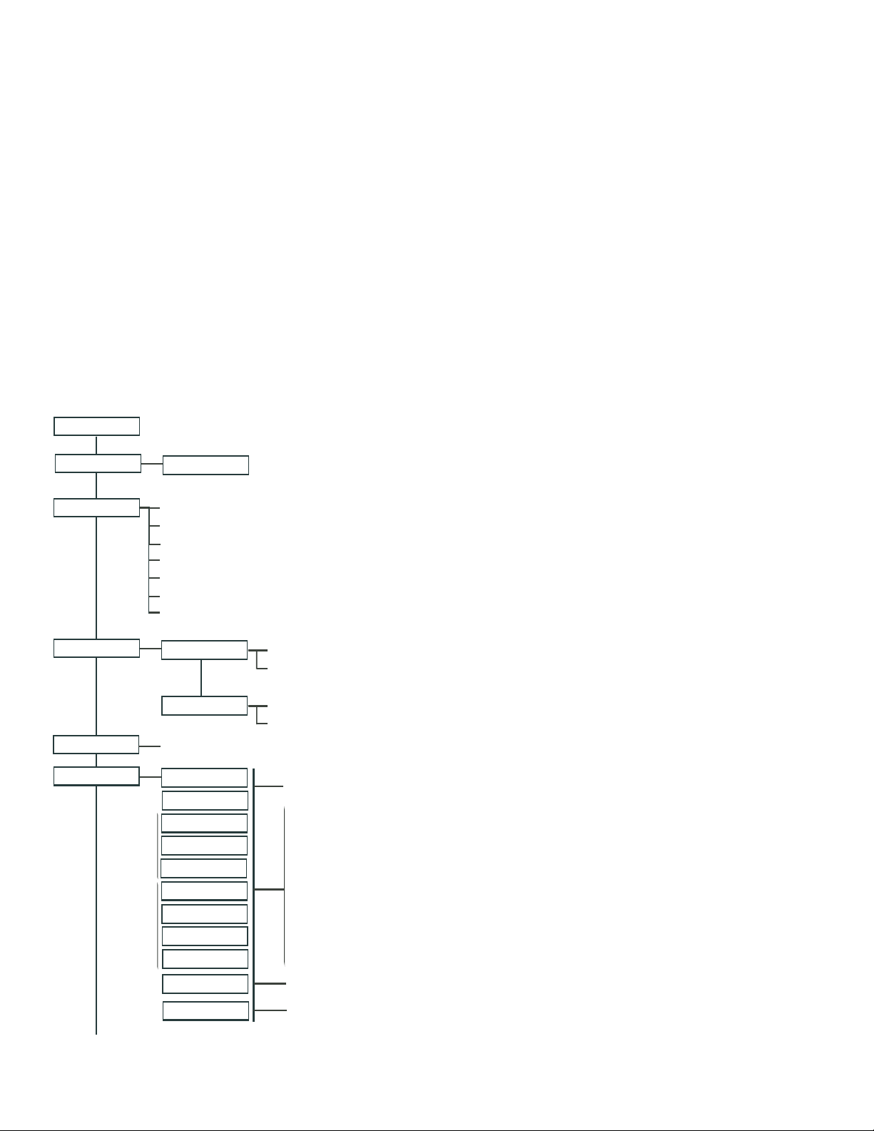
EasyTouch Menus
MAIN SCREEN
FEATURE CIR
LIGHTS
HEAT
DELAY CANCEL
SCHEDULES
EASYTOUCH 4
EASYTOUCH 8
FEATURE 1-8 [OFF]
MODES [6 LIGHT SHOWS, HOLD, RECALL, COLOR SWIM, COLOR SET]
COLORS [5 FIXED COLORS, HOLD, RECALL, COLOR SWIM, COLOR SET]
ALL ON (SWITCH ALL LIGHTS ON)
ALL OFF (SWITCH ALL LIGHTS OFF)
SYNC (SYNCHRONIZE COLORED LIGHTS)
MAGICSTREAM [TOGGLE THUMPER, HOLD, RESET, CHANGE MODE]
CONFIG (SETUP EIGHT LIGHT POSITIONS)
POOL TEMP/SRC
SPA TEMP/SRC
(DELAYED CANCELLED) PRESS RIGHT BUTTON TO ACTIVATE
SPA 0
POOL 0
AUX 1 0
AUX 2 0
AUX 3 0
AUX 4 0
AUX 5 0
AUX 6 0
AUX 7 0
FEATURE 1-8 0
AUX EXTRA 0
MANUALLY TURN A FEATURE CIRCUIT ON/OFF.
USE FEATURE CIRCUITS TO CONTROL PUMP SPEEDS AND VALVES.
TEMP (40˚ F - 106˚ F) OR (4˚ C - 41˚ C)
HEAT (OFF/HEATER/SOLAR/SOLAR PRF) - SOLAR/SOLAR PRF MUST BE ENABLED IN "SOLAR" MENU TO DISPLAY.
TEMP (40˚ F - 106˚ F) OR (4˚ C - 41˚ C)
HEAT (OFF/HEATER/SOLAR/SOLAR PRF) - "SOLAR/SOLAR PRF" MUST BE ENABLED IN "SOLAR" MENU TO DISPLAY.
HI-TEMP (SPA) / LO-TEMP (POOL) FOR SINGLE BODY SYSTEM (SEE SETTINGS MENU: CIRCUIT NAMES)
MODE: SCHEDULE
08:00A -- 05:00P (12:00 AM - 11:59 PM -12 HOURS)
S M T W T F S (DAYS OF THE WEEK)
MODE: EGG TIMER
TIME: 12:00 (00:00 - 23:59) / DON'T STOP
MODE: ONCE ONLY
08:00A (12:00 AM - 11:59 PM -12 HOURS)
S M T W T F S (SELECT DAY OF THE WEEK TO RUN PROGRAM)
MODE: NEW / DELETE / NONE
FEATURE 1 - 8
AUX EXTRA: AUXILIARY OUTPUT (USE DOWN ARROW BUTTON TO SWITCH ON/OFF). ONLY AVAILABLE IF
SOLAR PLUG (J17) IF NOT BEING USED FOR SOLAR EQUIPMENT.
Compool/EasyTouch Pool and Spa Control System Upgrade Installation and User’s Guide
Page 23

EasyTouch Menus (Continued)
()
SETTINGS
CLOCK
(OPTIONAL)
INTELLIFLO
INTELLICHLOR
(OPTIONAL)
DATE & TIME 1/2 - (MONTH/DAY/YEAR) - (DAY/HOUR/MINUTES/AM/PM)
DATE & TIMER 2/2 - DAYLIGHT SAVING: (AUTO/MANUAL)
CLOCK ADJUST 00:00 (0 TO 300) - (-300 TO -5) IN 5 SCEOND INCREMENTS
PUMP #1 - PUMP TYPE [VF, VS, NONE] - VF: FLOW (GPM), FILTERING, PRIMING, BACKWASH, VACUUM, STATUS
PUMP #2 - PUMP TYPE [VF, VS, NONE] - VS: SPEEDS (RPM), PRIMING, STATUS
INTELLICHLOR 1/2 - ENABLE (YES/NO), POOL MODE: 0 - 100 % (50% default) SPA MODE: 0% (2% default)
INTELLICHLOR 2/2 - SUPER CHLR (ON/OFF), RUN HOURS (0 -72)
15
THERMALFLO
(OPTIONAL)
CIRCUIT NAMES
CIRCUIT FUNC.
CUSTOM NAMES
VALVES
2-SPEED PUMP
SOLAR
DELAYS
F˚ / C˚
iS4
iS10
iSx PUMP CTRL
QUICK TOUCH
MAN HEAT [OFF/ON]
SETTINGS: ENABLE, DISABLE (NO/YES) - [HEATING, COOLING] - STATUS
CIRCUIT NAMES (1/18) - [SPA, POOL, AUX 1-7 (ET8), AUX 1-3 (ET4), FEATURE 1-8, AUX EXTRA
CIRCUIT: (SPA [MASTER SPA], POOL [MASTER POOL], AUX 1-7 (AUX 1-3), FEATURE 1-8, AUX EXTRA - FUNCTIONS: GENERIC, MASTER SPA, MASTER POOL,
MSTR CLEANER, LIGHT, SAM LIGHT, SAL LIGHT, PHOTON GENERATOR, COLOR WHEEL, SPILLWAY, FLOOR CLEANER, INTELLIBRITE, MAGICSTREAM
FREEZE: NO/YES
CSTM NAME 1/10 (ASSIGN UP TO 10 CUSTOM NAMES)
[USERNAME-01...10] (UP TO 11 ALPHANUMERIC CHARACTERS)
A: [NONE, SPA, POOL, AUX 1 - 3 (ET 4) - SPA, POOL, AUX 1 - 7 (ET 8), FEATURE 1-8, AUX EXTRA, HEATER] - (USED SOLAR IF SOLAR IS ENABLED)
B: [NONE, SPA, POOL, AUX 1 - 3 (ET 4) - SPA, POOL, AUX 1 - 7 (ET 8), FEATURE 1-8, AUX EXTRA, HEATER]
2-SPEED PMP 1/4 (ASSIGN UP TO 4 CIRCUITS)
CIRCUIT (NONE, SPA, POOL, AUX 1 - 3 (ET 4) - SPA, POOL, AUX 1 - 7 (ET 8), FEATURE 1-8, AUX EXTRA, SOLAR, HEATER, POOL HEATER, SPA HEATER, FREEZE)
SOLAR 1/2 - ENABLE (YES/NO) - HEAT PUMP (YES/NO) - SOLAR 2/2 (TEMPREATURE DIFFERENCE) - START (3˚-9˚ (6˚ default) - RUN (2˚-5˚) (3˚ default)
COOL DOWN (YES/NO) - VALVES (YES/NO)
FAHRENHEIT / CELCIUS
ASSIGN CIRCUITS 1/4
CIRCUIT - (NONE, SPA, POOL, AUX 1 - 7 (ET 8), AUX 1 - 3 (ET 4), FEATURE 1-8, AUX EXTRA, HEAT BOOST, HEAT ENABLE, PUMP INCRS, PUMP DECRS)
TOP ROW (1/5), BOTTOM ROW (1/5)
ASSIGN CIRCUITS 1/5 (NONE, SPA, POOL, AUX 1 - AUX 7 (ET 8), AUX 1 - AUX 3 (ET 4), FEATURE 1-8, AUX EXTRA, HEAT BOOST, HEAT ENABLE, PUMP INCRS, PUMP DECRS))
ASSIGN IS10 and IS4 PUMP CONTROLS [PUMP NUMBER 1/2, STEP RPM: 10-250, GPM: 1-10]
ASSIGN QT4 1/4 (ASSIGN UP TO 4 CIRCUITS)
CIRCUIT - (NONE, SPA, POOL, AUX 1 - AUX 7 (ET 8), AUX 1 - AUX 3 (ET 4), FEATURE 1-8, AUX EXTRA, HEAT BOOST, HEAT ENABLE)
SWITCH MANUAL HEAT ON OR OFF WHEN SPA IS MANUALLY SWITCHED ON (USE RIGHT BUTTON SELECT ON/OFF)
CALIBRATION
ERASE EEPROM
SET PASSWORD
WIRELESS ADDR
SPA SIDE [OFF/ON]
DIAGNOSTICS SOFTWARE REV (REVISION LEVEL FOR THE OUTDOOR AND INDOOR CONTROL PANEL)
ENABLE/DISABLE IS4 SPA-SIDE REMOTE
BOOTLOADER REV (REVISION LEVEL FOR THE OUTDOOR AND INDOOR CONTROL PANEL)
SELF TEST (STATUS: TESTING (FOLLOW ON-SCREEN PROMPTS TO TEST LCD AND BUTTONS) - CODE: 0 - SEE "TROUBLESHOOTING" SECTION FOR ERROR CODES)
CHLORINATOR
WATER TEMP (FAHRENHEIT/CELCIUS - STATUS DISPLAY ONLY)
SOLAR TEMP (FAHRENHEIT/CELCIUS - STATUS DISPLAY ONLY) - (DISPLAYS IF SOLAR IS ENABLED IN HEAT MENU)
AIR TEMP (FAHRENHEIT/CELCIUS - STATUS DISPLAY ONLY)
DISP OP CODES - DISPLAY? NO/YES (DISPLAYS TRANSMIT/RECEIVE PACKETS NUMBERS ON SCREEN)
CIR NAMES [ON/OFF] VIEW DEFAULT CIRCUIT NAMES BEFORE MODIFICATION.
RESET SYSTEM (REINITIALIZE INDOOR CONTROL PANEL - USE RIGHT BUTTON)
FLASH UPDATE (USED FOR FIRMWARE UPDATES VIA PC - PRESS MENU TO ABORT)
WATER (FAHRENHEIT/CELCIUS) - AIR (FAHRENHEIT/CELCIUS) - SOLAR (FAHRENHEIT/CELCIUS) - SOLAR MUST BE ENABLED IN "HEAT" MENU TO DISPLAY
ERASE ALL (YES /NO) - ARE YOU SURE? (YES/NO)
SET PASSWORD: {XXXX} 4 DIGITS - ENABLE / DISABLE [NO/YES]
SET AN ADDRESS FOR EASYTOUCH WIRELESS CONTROL PANEL
SALT LEVEL: DISPLAYS CURRENT SALT LEVEL (XXXX) PPM
STATUS: OK - NO ERRORS (SUPER CHLORINATE, COM LINK ERROR, CHECK FLOW / PCB,
LOW SALT, VERY LOW SALT, HIGH CURRENT, CLEAN CELL!!, LOW VOLTAGE)
Compool/EasyTouch Pool and Spa Control System Upgrade Installation and User’s Guide
Page 24

16
EasyTouch Menus
From the EasyTouch control panel menus you can schedule everyday pool/spa, heating, filtration and cleaning.
Lights and laminars can also be scheduled to switch on and off at specific times. The “Settings” and
“Schedule” menus are typically used most often for daily spa and pool operations. The “Settings” menu is used
by the pool installer to setup installed equipment which is connected to each output relay (filter pump, auxiliary
relays, heater, valves, lights, etc.). For EasyTouch equipment installation instructions, see the EasyTouch
Installation Guide (P/N 520584).
Main Screen
AUTO HEATER
SPA 95°F / 100°F
AIR 70°F
MON 09:30 AM
AUTO HEATER
POOL 85°F / 95°F
AIR 70°F
MON 10:30 AM
AUTO
AIR 70°F
MON 11:30 AM
The EasyTouch main screen displays the current mode of operation
(AUTO/SERVICE/TIMEOUT), heat source being used, spa (or pool) actual water
temperature (95° F), current heater set point temperature (100° F) and the current
ambient air temperature (air sensor). Degree units can be displayed in either
Fahrenheit (default) or Celsius (see page 44). If the second display line is blank and
the heat source is not displayed, there is no spa or pool function currently active. The
main screen is automatically displayed if there is no control panel menu activity for
five minutes. If there is an IntelliChlor salt chlorinator generator being used, pool and
spa sanitizer settings, and salt levels can be viewed in the Diagnostics, “Chlorinator,”
settings (see page 53).
Main Screen Description
AUTO: EasyTouch is in normal (automatic) operating mode. For information about “Service” and “Timeout”
operating modes, see page 4.
HEATER: The selected heat source as selected in the “Heat” menu (see page 25). The heat options are:
OFF - No heating even though pump and other circuits may be operating.
•
• HEATER - Gas heater only.
• SOLAR ONLY - Solar heating system to be the only heat source. In order to display “Solar Pref.” on
the main screen, you must first enable solar in the “Solar” menu (see page 42).
• SOLAR PREF. - (Solar Preferred) - For when solar and gas heating are combined, and you want to
use solar heating only when it is most effective. In order to display “Solar Pref.” on the main screen,
you must first enable solar in the “Solar” menu.
SPA: “SPA” is displayed after the Valves (V) button is pressed to set in “spa” mode then the Filter (F)
button is pressed to switch the filter pump on, rotate the valve actuator (to isolate spa water from pool water),
and switch the heater on (if enabled in the “Heat” menu). Pressing the Valves (V) button alternates between
“Pool” and “Spa” mode. The temperature unit displayed on the left side is the actual water temperature (95°
F) and the set point temperature (100° F) as set in the “Heat” menu is displayed on the right side. If this
display line is blank, it indicates no spa or pool function is currently active. For Hi-Temp controls (EasyTouch
single body system), see page 37.
POOL: “POOL” is displayed after the Filter (F) button is pressed to switch the filter pump on, rotate the
valve actuator to isolate the pool water from the spa water, and switch the heater on (if enabled in the “Heat”
menu). Pressing the Valves (V) button alternates between “Pool” and “Spa” mode. The temperature unit
displayed on the left side is the actual water temperature (95° F) and the set point temperature (100° F) as set
in the “Heat” menu is displayed on the right side. If this display line is blank, it indicates no spa or pool function
is currently active. For Lo-Temp controls (EasyTouch single body system), see page 37.
AIR: Displays the actual outside ambient air temperature (70° F) as recorded by the air sensor located near
the EasyTouch load center.
DAY and TIME: The current system day and time (AM/PM). See the “Clock” menu to set the system day and
time (page 31).
Compool/EasyTouch Pool and Spa Control System Upgrade Installation and User’s Guide
Page 25

Feature Circuits Menu
There are eight (8) “Feature Circuits” that can be used to control IntelliFlo pump speeds or valves actuators
for a spa spillway. Unlike an auxiliary relay circuit, a “Feature” circuit does not connect directly to a relay.
“Feature” are turned on and off from the control panel “Feature” circuit menu.
Feature Circuits
Getting There
▲
Menu F. Circuits
To switch a feature circuit ON or OFF:
17
F. Circuits
Lights
Heat
Delay Cancel
FEATURE 1 [ON]
FEATURE 2 [OFF]
FEATURE 3 [OFF]
FEATURE 4 [OFF]
FEATURE 5 [ON]
FEATURE 6 [OFF]
FEATURE 7 [OFF]
FEATURE 8 [OFF]
Right button: Select the feature circuit to turn ON or OFF..
Up/Down buttons: Choose assigned feature circuit: FEATURE 1 - 8.
Right button: Switch the selected feature circuits ON or OFF.
When finished, press the Menu button twice to return to the main screen.
Compool/EasyTouch Pool and Spa Control System Upgrade Installation and User’s Guide
Page 26
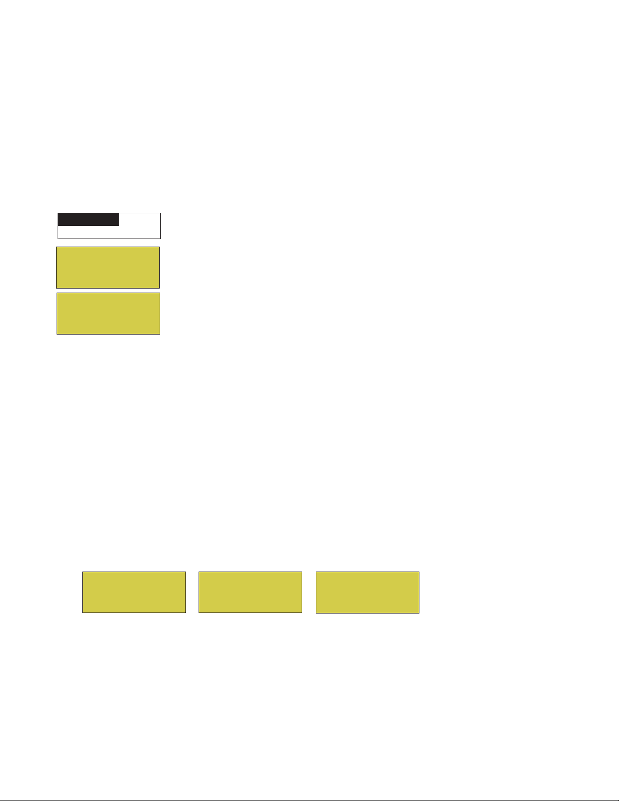
18
Lights Menu
From the Lights screen you can manually switch all lights on or off, and synchronize colored lights. Up to
eight (8) lights can be independently controlled from the Lights screen. Each light requires a separate
auxiliary relay circuit. Up to four lights can be assigned on each auxiliary circuit. A circuit name must be
assigned to the AUX relay circuits which controls the light. Verify that IntelliBrite, SAm and/or SAL, and/or
FIBERworks have been selected in Circuit Function. If FIBERworks lighting is being used, it also has to be
set up as a Photon Generator® light source (PHOTON GENERATOR) for the circuit controlling the light bulb,
and COLOR WHEEL for the circuit controlling the color wheel. For more information about setting up lights,
see “Settings Menu: Circuit Function,” on page 39.
The Color Swim and Color Set Lighting Features
Getting There
MENU LIGHTS LIGHTS
▲
Modes
Colors
All On
All Off
Hold
Recall
Color Swim
Color Set
▲
The Color Swim and Color Set lighting features is selected from the LIGHTS > MODES and (COLORS)
menu. At least two (2) Pentair Water Pool and Spa
®
, IntelliBrite®, SAm®, SAL®, and/or FIBERworks® lighting
systems are required to use the lighting features.
• Color Swim - Select the Color Swim feature in the MODES and COLORS menus to start lights to
transition through colors in sequence to give the appearance of colors dancing through the water. You
can adjust the delay of each light to make the colors move at different speeds using the LIGHTS >
CONFIG option. This lighting feature requires a separate relay for each light. To switch off the Color
Swim feature, select the AUX button assigned to the light circuit or select ALL OFF in the Lights
menu.
• Color Set - Select the Color Set feature in the MODES and COLORS menus to switch the light on
using specific color as selected in the COLORS menu. This feature requires a separate relay for
each light. To switch off the Color Swim feature, select the AUX button assigned to the light circuit
or select ALL OFF in the Lights menu.
• Configure - Select “Configure” to setup the positions of the lights the pool. Up to eight (8) lights can
be assigned a position. For more information see page 22.
All On
All Off
Sync
Configure
1- [NONE ]
2- [NONE ]
3- [NONE ]
4- [NONE ]
1- [AUX 1 ]
2- [LT.GREEN ]
3- [1ST POSITION ]
4. [DELAY 5 SECS]
• Sync - Select the Sync feature in the LIGHTS menu to switch on all IntelliBrite, SAm, SAL, or
FIBERworks color changing lights and synchronize their colors.
• Smart Start (SS: Yes/No) - Select Smart Start in the Schedules menu (see page 27). The Smart Start
feature automatically starts changing colors when the lights are programmed to switch on. Smart
Start is used when Color Swim and IntelliBrite show modes are being used.
Compool/EasyTouch Pool and Spa Control System Upgrade Installation and User’s Guide
Page 27
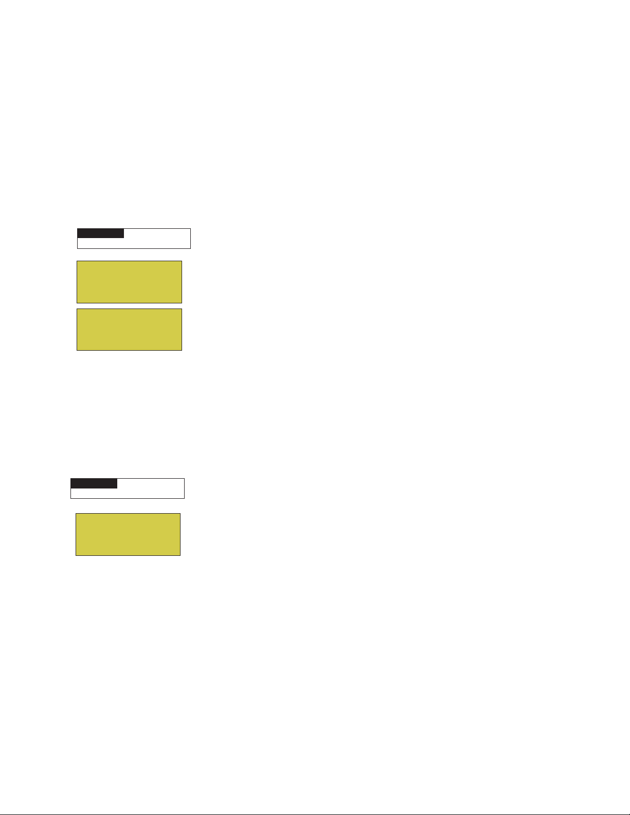
Setting up Lights
The following section describes how to assign a light circuit name and function to control Pentair Water Pool and
Spa IntelliBrite, SAm and/or SAL, and/or FIBERworks lights.
Assign the Light Circuit Name and Function
The first step in setting up a light circuit is to assign a name to the relay circuit (example; AUX 3, as “Pool Light”),
then assign the name “Pool Light” circuit in the Circuit Func. menu as a “light” circuit (IntelliBrite, SAM, SAL..).
The light circuit functions are: Light, SAM, SAL, Photon Generator, Color Wheel, Spillway, MagicStream and
IntelliBrite (see page 40). After assigning the circuit name and function, the light circuit name “Pool Light” can be
setup in the CONFIG menu for light position, color etc.
To assign a circuit function:
Getting There
MENU ▼ SETTINGS ▼ CIRCUIT NAMES
IntelliFlo
IntelliChlor
Circuit Names
Circuit Func.
Circuit Names
Circuit #: 1/18
Circuit : AUX 1
[POOL LIGHT ]
▲
Up/Down buttons: Select the circuit number 1/18. Press the Up button two times
to select AUX 1 to choose this circuit for a light circuit On/Off button. The generic
circuits names are: Spa, Pool, Aux 1-7, FEATURE 1-8 (Ft. 1-8), AuxX (Aux Extra).
The circuit number (1/18) corresponds to its assigned circuit name.
Right button: Select the EasyTouch preset circuit names and user defined custom
circuit names.
Up/Down buttons: Scroll through the list of preset names (see page 38 for a
complete list of circuit names). Select a name that describes where the light is located
or that suits the function, such as “Pool Light.” AUX 1 has now been assigned the
circuit name “Pool Light.” If you cannot find a name to match your circuit, you can
create your own custom name (see page 41). Repeat this step for all the circuit
buttons that you wish to assign names to. “Aux Extra” is only available if the Solar
output (J17) plug on the EasyTouch motherboard is not being used for solar
equipment. The Down arrow button is used to turn the “extra” circuit on and off.
19
Getting There
MENU ▼ SETTINGS ▼ CIRCUIT FUNC.
Circuit / Func. :
[POOL LIGHT ]
[INTELLIBRITE ]
Freeze: No
Press the Menu button to return to the Settings menu. Press the Down button to and
select “Circuit Func.” Press the Right button to access the Circuit Func. menu.
▲
Up/Down buttons: Select the already assigned circuit name “Pool Light.”
Right button: View “Circuit Functions” to assign to light circuit “Pool Light.”
Up/Down buttons: Select the type of light circuit function to use. The circuit
function names are: LIGHT, SAM LIGHT, SAL LIGHT, PHOTON GEN, COLOR
WHEEL, VALVE, SPILLWAY, FLOOR CLEANER, INTELLIBRITE,
MAGICSTREAM, GENERIC, and MSTR CLEANER. For a complete list of preset
circuit functions, see “Preset Circuit Functions” on page 40.
Note: To use the “Color Swim” or “Color Set” feature, select IntelliBrite, SAM, SAL,
Photon Generator or Color Wheel. Select “MagicStream” for MagicStream laminars.
Press the Menu button three times to return to the main screen.
Compool/EasyTouch Pool and Spa Control System Upgrade Installation and User’s Guide
Page 28

20
Setting up lights
From the Lights screen you can manually switch all lights on or off, synchronize colored lights, and activate
color light shows. Up to eight light circuits can be configured from the “Config” light menu. Each light must
have its own relay and separate circuit.
Setting up IntelliBrite Light Circuits
Before configuring the lights, be sure the auxiliary (AUX) circuits that control the IntelliBrite lights have been
assigned as an “IntelliBrite” light. For more information about “Circuit Functions” (page 39) and “Circuit
Names,” (page 37).
Lights Menu
To access the Lights menu screen, press Menu > Lights. The Lights menu settings are: MODES, COLORS,
ALL ON, ALL OFF, SYNC, MAGICSTREAM, CONFIG:
Getting There
MENU LIGHTS LIGHTS
▲
Modes (IntelliBrite Color light shows, Color Swim, Color Set)
▲
To access the Modes menu, press Menu > Lights > Modes. There are six pre-programmed color light
shows to choose from. From the “Modes” screen you can select various preset show color lighting effects,
such as “American mode” and “Sunset mode”, “Color Swim” or “Color Set.” Using the “Hold” and “Recall”
feature (see page 21) you can also capture and save a unique color light show effect to recall at a later time.
The IntelliBrite color “Mode” settings light shows are:
• Party: Rapid color changing building the energy and excitement
• Romance: Slow color transitions creating a mesmerizing and calming effect
• Caribbean: Transitions between a variety of blues and greens
• American: Patriotic red, white and blue transition
• Sunset: Dramatic transitions of orange, red and magenta tones
• Royalty: Richer, deeper, color tones
IntelliBrite Light: If the IntelliBrite light was not previously on, after selecting a color show mode, no
illumination will occur for up to ten (10) seconds (depending on the selection), then a white light will
momentarily illuminate, followed by the color show mode selection. If the light was previously on,
selecting the a color show mode button will momentarily illuminate the previously selected color before
changing to the selected color show.
Modes (Color Swim)
The Color Swim feature cycles through white, magenta, blue and green colors. Using IntelliBrite lights, Color
Swim emulates the Pentair Water Pool and Spa SAM and SAL Color Swim feature.
IntelliBrite Light Color Swim/Color Set: If the light was not previously on, after selecting Color Swim,
no illumination will occur for approximately six (6) seconds followed by the selection. If the light was
previously on, after selecting the Color Swim feature, the previously selected color will momentarily
illuminate, no illumination will occur for approximately six (6) seconds followed by the selection.
Compool/EasyTouch Pool and Spa Control System Upgrade Installation and User’s Guide
Page 29

Setting up lights (Continued)
Modes (Color Set)
The “Color Set” feature allows any combination of up to eight IntelliBrite lights, and Pentair SAm, SAL and or
Fiberworks lighting to be preset to specific colors. Fixed light colors are selected and activated from the Colors
screen.
IntelliBrite Light: If the light was not previously on, after selecting the fixed colored light, no
illumination will occur for approximately six (6) seconds followed by the selection. If the light was
previously on, after selecting the colored light, the previously selected color will momentarily illuminate,
no illumination will occur for approximately six (6) seconds followed by the selection.
Colors
Choose any one of the five fixed colors to create a spectacular underwater lighting effect. The fixed colors
are: Blue, Green, Red, White and Magenta. You can switch each fixed colored light on or off from the
Colors screen.
IntelliBrite Light: If the light was not previously on, after selecting a fixed colored light, no illumination
will occur for up to ten (10) seconds (depending on the selection), then a white light will momentarily
illuminate, followed by the color selection. If the light was previously on, selecting the a color button
will momentarily illuminate the previously selected color before changing to the selected color.
21
To select a fixed color press:
Blue
Green
Red
White
Green
Red
White
Magenta
Magenta
Menu > Lights > Modes > Colors:
Up/Down buttons: Choose a color for the light.
Right button: Switch the selected colored light ON. To switch the light off, go to
the main Lights menu and select All Off, or press the AUX button assigned to the
light. The AUX button will also switch the light on.
Press the Menu button three times to return main menu.
WARNING - IntelliBrite Lights: During the off/on switching process, before
the selected color is displayed, no illumination will occur. This operating mode is
normal during the switching process. During this period the pool and spa will be
dark and precautions should be taken to avoid unforeseen accidents. Failure to
observe this warning may result in serious injury or death to pool and spa users.
Hold/Recall
Select Hold and Recall from the “Modes” or “Color” screen to capture and save a unique color effect and
recall it at a later time. For example, while a light show (Romance Mode) is active, select “Hold” to save the
exact colors that are being displayed, then later, to recall the exact color effect, select “Recall.”
Note: After selecting Hold or Recall, no illumination will occur for up to 10 seconds, then a white light
will momentarily illuminate, followed by the saved color.
All On / All Off (Lights Menu)
Select All On or All Off from the Lights screen to manually switch all lights on or off, including any
MagicStream laminar circuits. Press the control panel auxiliary button (AuxX) assigned to a light circuit will
also switch a light on or off.
Sync
Select Sync from the “Lights” screen to synchronize colors for all IntelliBrite, SAm, SAL and FIBERworks
color changing lights.
Compool/EasyTouch Pool and Spa Control System Upgrade Installation and User’s Guide
Page 30

22
Setting up lights (Continued)
Config
From the “Config” screen you can setup the IntelliBrite light position, and specify the color of each pool and
spa light. Any combination of up to eight IntelliBrite lights, Pentair SAM, SAL and or Fiberworks lights can be
preset for specific colors and position when using the “Color Swim” and “Color Set” feature. Fixed light color
are selected and activated from the Colors screen. Note: The “Config” menu settings do not apply to the
MagicStream laminars.
To select configure a light position and color:
Up/Down buttons: Choose the light circuit (1-8) to configure. Select an available
1- [POOL ]
2- [SPA ]
3- [BACK YARD ]
4- [AUX 4 ]
auxiliary circuits.
5- [NONE ]
6- [NONE ]
7- [NONE ]
8- [NONE ]
auxiliary circuit (NONE). For more about assigning an auxiliary circuit to a light,
see “Circuit Functions (page 39) and “Circuit Names” (page 37). Up to eight (8)
Right button: Select the light to setup.
Up/Down buttons: Select the light circuit.
Right button: Select the light color selection.
Up/Down buttons: Select the light color (Blue, Cyan, Green, Lt. Green,
White, Lt. Magenta, Magenta, Lavender).
Right button: Select the light position selection.
[ AUX 4 ]
[ LAVENDER ]
[ 1ST POSITION ]
[ DELAY 5 SECS ]
Up/Down buttons: Select the light position. A light can be assigned to any
position from 1 through 12. To ensure that the “Color Swim” and “Color Set”
lighting feature color effects are correct, set the position of the light according to
where it’s located in the pool or spa. Position 1 will lead all the other lights in the
color changing sequence. Position 2 follows Position 1 and so on. There are 12
position to choose from. More than one light may be assigned to the same position
number so that their colors may be synchronized. For example, to make the colors
swim right to left, make your right most light Position 1. You may need to go
back to and scroll through your lights to find the right most light, and set it as
Position 1.
Right button: Select the light delay selection. The Delay time between two or
more lights can be set from 0 to 60 seconds. Use a higher delay time for lights
spread further apart. Try five seconds for all lights and observe the effect. Use
different time settings to achieve unique lighting moods and effects.
Menu > Lights > Config:
Press the Menu button to setup other lights or press Menu button four times
to return main screen.
Setting up SAM, SAL, PG2000, Color Wheel Lights
Before using the lighting feature “Color Swim” or “Color Set” with Pentair SAM or SAL lights, make sure the
AUX relay circuits which control the lights have been assigned as “light” circuit and that the name (AUX 1,
AUX 2) has been changed to best fit the light being used. Verify that SAm and/or SAL, and/or FIBERworks
have been assigned in “Circuit Functions” as SAM or SAL light. If FIBERworks lighting is incorporated, it
also has to be set up as a “PHOTON GENERATOR” light for the circuit controlling the light bulb, and
COLOR WHEEL for the circuit controlling the color wheel it self. The circuit light “functions” are: Light,
SAM, SAL, Photon Generator, Color Wheel, and IntelliBrite, see page 40 for a more information.
Compool/EasyTouch Pool and Spa Control System Upgrade Installation and User’s Guide
Page 31

Setting up MagicStream Laminars
The MagicStream® Laminar provide a clear, turbulence-free stream of water that is lit with a fiber optic cable,
or an LED light for a dazzling nighttime effect. The 12 VAC powered LED light can generate a series of
multicolored light shows, or can be set to display a continuous, single color. If desired, the built-in solenoid
“thumper” can create a random “wrinkle,” in the Laminar’s stream, causing it to display a brilliant spot of light
that moves along the stream’s arc. The light enhancer can be adjusted to maximize the light in the arc.
Up to twelve (12) MagicStream Laminar circuits can be displayed on the main Lights screen, assuming each
laminar has its own relay and separate circuit.. From the Lights screen you can activate the MagicStream
laminars (changing color modes, turn Thumper on/off, Hold and Reset). For more information, see the
MagicStream Installation Guide, P/N 520969.
Setting up MagicStream Laminar LED Lights
To setup MagicStream laminar circuits, first assign each laminar auxiliary relay circuit a circuit name (see
“Circuit Names” page 37, then assigned the laminar relay circuit name to “MAGICSTREAM” in the circuit
functions menu (Circuit Func.).
To setup the MagicStream laminar circuit names and function:
Getting There
MENU ▼ SETTINGS ▼ CIRCUIT NAMES
▲
23
IntelliFlo
IntelliChlor
Circuit Names
Circuit Func.
Circuit Names
Circuit #: 1/18
Circuit : AUX 1
[STREAM ]
Getting There
MENU ▼ SETTINGS ▼ CIRCUIT FUNC.
Circuit / Func. :
[STREAM ]
[MAGICSTREAM ]
Freeze: Yes
Up/Down buttons: Select the circuit number 1/18. Press the Up button two times
to select AUX 1 to choose this circuit for the MagicStream circuit On/Off button. The
generic circuits names are: Spa, Pool, Aux 1-7, FEATURE 1-8 (Ft. 1-8), AuxX (Aux
Extra).
The circuit number (1/18) corresponds to its assigned circuit name.
Right button: Select the EasyTouch preset circuit names and user defined custom
circuit names.
Up/Down buttons: Scroll through the list of preset names (see page 38 for a
complete list of circuit names). Select a name that describes where the MagicStream
laminar is located or that suits the function, such as “Stream.” AUX 1 has now been
assigned the circuit name “Stream.” for the first MagicStream laminar. Repeat this
step for the next laminar circuit. If you cannot find a name to match your circuit, you
can create your own custom name (see page 41). “Aux Extra” is only available if the
Solar output (J17) plug on the EasyTouch motherboard is not being used for solar
equipment. The Down arrow button is used to turn the “extra” circuit on and off.
Press the Menu button to return to the Settings menu. Press the Down button to and
▲
select “Circuit Func.” Press the Right button to access the Circuit Func. menu.
Up/Down buttons: Select the already assigned circuit name “Stream.”
Right button: View the “Circuit Functions” to assign to laminar circuit “Stream.”
Up/Down buttons: Select the type of circuit function to use, in this case select
“MAGICSTREAM.” The circuit function names are: LIGHT, SAM LIGHT, SAL
LIGHT, PHOTON GEN, COLOR WHEEL, VALVE, SPILLWAY, FLOOR
CLEANER, INITELLIBRITE, MAGICSTREAM, GENERIC, and MSTR
CLEANER. For a complete list of preset circuit functions, see “Preset Circuit
Functions” on page 40.
Right button/ Up Button: Turn “Freeze” protection ON.
Press the Menu button three times to return to the main screen.
Compool/EasyTouch Pool and Spa Control System Upgrade Installation and User’s Guide
Continue on next page...
Page 32

24
Using the MagicStream Laminar Features
The MagicStream laminar features are displayed in the MagicStream menu. Each time a MagicStream feature
is activated, MagicStream resumes with the same features in operation as when last switched off. The
MagicStream features are as follows:
Toggle Thumper - Pressing this button creates a "wrinkle" in the laminar stream, producing a brilliant spot
of light in the laminar arc.
Hold - Select Hold to capture the current color effect while colors are changing. The colors will stop
changing. Selecting Hold again will resume the color changing mode.
Reset - Pressing this button reverts to the Random color changing mode with the Thumper ON.
Change Mode - Pressing this button (each successive OFF/ON combination) will cycle through Sync,
Random and Party. Color changing mode - The color of the light changes automatically, according to one
the following three programs:
Sync - Colors will change at ten second intervals. In this mode, multiple laminars will synchronize
colors together. Note: To sync multiple laminars (two or more AUX circuits), be sure to define the
“MagicStream” circuits in the “Circuit Functions” menu.
Random - Colors will change at ten (10) second intervals in a random sequence. In this mode,
multiple laminars will NOT synchronize colors together.
Party - Colors will change randomly and slowly at first, then speed up, until the sequence ends
with quick flashes and strobes. The sequence then repeats, beginning with the slow changes. In
this mode, multiple Laminars will NOT synchronize colors together.
To access the MagicStream laminar features:
Getting There
MENU LIGHTS LIGHTS
▲
All On
All Off
Sync
MagicStream
Toggle Thumper
Hold
Reset
Change Mode
Change Mode
▲
Down button: Choose MagicStream.
Right button: Select MagicStream.
Up/Down button: Select the desired MagicStream features.
Right button: Use this button to activate the selected MagicStream feature. After
the button is pressed, the following screen displays the name of the selected feature
(indicating that the MagicStream feature has been activated) then returns to the
MagicStream feature menu.
Press the Menu button three times to return to the main screen.
Compool/EasyTouch Pool and Spa Control System Upgrade Installation and User’s Guide
Page 33

Heat Menu
Getting There
MENU HEAT
▲
Use the heat menu settings to specify the set point temperature and select the heat source for the pool and spa
water. The water will begin to heat whenever the heater is manually switched on, (by pressing the Valves (V)
button (on the Outdoor Control Panel) or the “Pool” or “Spa” button on the Indoor Control Panel), even if the
heater is set to off. The spa will also begin to heat when switched on by the optional iS4/iS10 Spa-Side remote,
or EasyTouch wireless remote. The EasyTouch system allows for solar and conventional heaters. The
EasyTouch will use the heating source that is selected. The heat source selections are:
•
OFF - No heating even though pump and other circuits may be operating.
HEATER - Gas heater only. Use the Heater button to automatically switch the heater on which
•
controls the output between a “forced off” state and a normal, automatic thermostatic control
operating state. The heater will continue heating the water until the heater’s current highest set point
temperature triggers the heater sensor (approximately 104° F or 40° C). Note that the Heater button
on the control panel does not activate the pump. Do not activate the heater without running the pump.
The heater will not run if water flow is not detected.
SOLAR ONLY - Solar heating system to be the only heat source. In order to display “Solar Pref.” on
•
the main screen, you must first enable solar in the “Solar” menu (see page 42).
SOLAR PREF. (Solar Preferred) - Solar and gas heating systems are installed, and you want to use
•
solar heating only when it is most effective. In order to display “Solar Pref.” on the main screen, you
must first enable solar in the “Solar” menu. To set the spa temperature and select the heat source:
25
Pool Temp/Src
To set the pool temperature and select the heat source:
POOL Temp/Src
SPA Temp/Src
POOL
Temp: 72° F
Heat: Off
Right button: Select pool temperature and heater options.
Up/Down button: Set the pool temperature (from 40° F to 104° F).
Right or Left button: Select Heater options.
Up/Down: Set Heater option: Off, Heater, Solar, or Solar Preferred.
Press the Menu button to save the settings and to return to the previous menu or
press the button again to return to the main screen.
Spa Temp/Src
To set the spa temperature and select the heat source:
Right button: Select spa temperature and heater options.
POOL Temp/Src
SPA Temp/Src
SPA
Temp: 85° F
Heat: Off
Up/Down button: Set the spa temperature (from 40° F to 104° F or 4° C to 40° C).
Right or Left button: Select Heater options.
Up/Down: Set Heater option: Off, Heater, Solar, or Solar Preferred.
Press the Menu button to save the settings and to return to the Heat menu or press
the button again to return to the main screen.
Note: For an EasyTouch single body system, “Pool” and “Spa” modes are Lo- Temp (Pool) and
Hi-Temp (Spa) temperature controls. For more information, see “Hi-Temp/Lo-Temp Controls for Single
Body Systems,” on page 37.
Compool/EasyTouch Pool and Spa Control System Upgrade Installation and User’s Guide
Page 34

26
Delay Cancel Menu
Use the Delay Cancel feature for service or testing purposes. For convenience, on a onetime basis, the Delay
Cancel feature will cancel the following safety delays. Please note, generally there is no need to cancel any of
the following delays except for servicing or testing the system.
• Heater Cool-Down Delay Cancel: Shuts Filter Pump off immediately.
• 2-Speed Filter Pump five-minute START on HIGH SPEED Delay Cancel: Shifts pump to low
speed.
• Automatic Pool Cleaner START Delay: Starts Cleaner Pump immediately, without normal delay in
which the filter pump first runs for 5 minutes.
• Automatic Pool Cleaner SOLAR Delay: Allows Cleaner Pump to run even though solar delay has
shut it off for 5 minutes.
Some heaters require a cool-down cycle before being switched off. This can be setup in the menu to run the
filter pump an additional ten minutes to dissipate residual heat built up inside the heater combustion chamber.
The Delay Cancel feature is mainly for use by service technicians when it’s necessary to shut the filter pump
off immediately, and know the heater has not been running. Heaters manufactured by Pentair Water Pool and
Spa do not require this cool-down period and do not need the delay to be set up.
Note: For Information about assigning delays to the pool and spa valves, refer to “Settings Menu:
Delays” on page 43.
Getting There
MENU ▼ DELAY CANCEL
▲
Delay Cancel
To activate Delay Cancel:
F. Circuits
Lights
Heat
Delay Cancel
Up/Down button: Select Delay Cancel.
Right button: Use this button activate Delay Cancel for one time only. “Delay
Cancelled” is displayed after pressing the Right button.
Press the Menu button to return to the main screen.
Compool/EasyTouch Pool and Spa Control System Upgrade Installation and User’s Guide
Page 35

Schedules Menu
Use the Schedules menu to create programs to schedule start and stop times to automatically run equipment,
such as pumps and lights. Any circuit can be programmed to switch on and off at a specific time on every or
any specific day of the week. The number of programs that can be created for circuits are as follows:
• Up to 12 total programs can be created for all circuits combined.
• One circuit can have up to a maximum of 9 programs (9/9), which leaves 3 programs that can be
used by one circuit or three separate circuits for a total of 12 programs.
Using the Schedules menu
Use the Schedules menu features to program operating schedules for the pool, spa and auxiliary circuits:
Getting There
MENU ▼ SCHEDULES SPA
▲
27
SPA 0
POOL 0
AUX 1 0
AUX 2 0
SPA 0/0
Mode: None
SPA 0/0
Mode: New
SPA 1/1
Mode: Schedule
08:00A - 05:00P
_
smtwtfs SS: N
SPA 1/1
Mode: Egg Timer
Timer: 12:00
SPA 1/1
Mode: Once Only
08:00A
_ _ _
mtwtfs
s
SPA 1/1
Mode: New
SPA 1/1
Mode: None
SPA 1/1
Mode: Delete
Choose the circuit to program
Up/Down button: Select the generic circuit name to program: Spa, Pool, Aux 1-7,
Feature 1- 8, Aux 1-3 and Aux Extra. Aux Extra is only available if the Solar output is
not being used. See Solar button on page 5 for details.
The current number of programs for each circuit is displayed opposite the circuit
name. A circuit can have up to 9 programs (9/9). Three additional programs can be
assigned to another circuit or three separate circuits for a maximum of 12 programs.
Create a new program
The current number of programs for each circuit is indicated opposite to the circuit
name. 0/0 indicates no programs assigned to this circuit.
Right button: Select “Mode” selection.
Up/Down button: Select New to create a new program. Use “None” when a circuit
has existing programs and you wish to exit the “Mode” selections without modifying
the existing programs.
Choose the type (Mode) of program to run
After selecting “New” the current program number (1/1) for this circuit is displayed.
Right button: Select “Mode” selection.
Up/Down button: Choose the program to run: Schedule, Egg Timer, Once Only,
New, Delete, and None. If there are existing programs assigned to this circuit, use
these buttons to view and select the existing program settings.
Mode Selection:
Schedule: Set start, stop times and the day(s) of the week to automatically switch
pool/spa circuits on or off. Default run time for the “Schedule” feature is 8:00 AM to
5:00 PM. If you program the start and stop times the same the schedule is will run for
24 hours. Note: SS: N (Smart Start) is displayed if a light circuit is being
scheduled (see page 18).
Egg Timer: A one time program that switches on a function at a specific time, and
counts down the preset time to the switch off the function. After the “Egg Timer”
schedule has finished, the system can be operated in manual mode. The “DON'T
STOP” option allows a circuit to run continuously until its switched off manually.
Once Only: Schedule a circuit to switch on at a particular time on a onetime basis.
New: press the Right button to create a new program.
Delete: Select the program and press the Right button to delete it.
None: Press the Right button to exit the “Mode” selections without modifying the
program.
Compool/EasyTouch Pool and Spa Control System Upgrade Installation and User’s Guide
Page 36

28
Schedules Menu (Continued)
Schedule your spa/pool pump to turn on
Use the Schedule feature to set the time and day(s) when to switch the filter pump on and rotate the pool or
spa valves into the “Spa” or “Pool” position. The heater will automatically heat the spa or pool water up to the
set point temperature as set in the “Heat” menu (see page 25). If the pool has a separate jet pump or blower
controlled by AUX 1 and/or AUX 2 , these need to be scheduled separately.
Schedule Example
When a circuit relay is switched on manually, it remains on until you either switch it off manually, or the next
time the relay is scheduled to be switched off. For example, if the filter pump or any circuit is scheduled to run
from 9 AM to 4 PM and the programmed schedule is turned OFF at 1:00 PM and then turned on at 1:10 PM,
the circuit will turn OFF at its programmed OFF time of 4:00 PM. But if the circuit is turned on after 4:00 PM,
the factory set Egg Timer of 12 hours is now engaged. So if the circuit was turned on at 6:00 PM that circuit
will turn off at 6:00 AM (12 hours later). If the circuit was turned ON at 5:00 PM and because a programmed
OFF time had been set to turn off at 4:00 PM, the circuit would operate for 11 hours. A spa or pool program
can be overridden using the Spa button or Pool button to switch the circuit on. If you program the start and
stop times the same, the schedule will run for 24 hours if scheduled to run for one day. In “Service” mode, a
pool or spa program can be overridden using the Filter (F) button and pool/spa Valves (V) button on the
outdoor control panel in the EasyTouch load center. Note: The following example describes how to use the
“Schedule” feature to program the spa circuit to switch the filter pump on and rotate the valves into the
“Spa” position and switch the heater on. This example can also be used to program when to filter and
heat your pool, and switch light or auxiliary circuits on or off.
To create a schedule for your spa or pool pump to turn on:
Getting There
MENU ▼ SCHEDULES SPA
SPA 0
POOL 0
AUX 1 0
AUX2 0
▲
Right button: Select the SPA or POOL circuit. The available generic circuit names
are: Spa, Pool, Aux 1-7, Feature Circuit 1-8 and Aux Extra. Aux Extra is only
available if the Solar output (J17) plug on the EasyTouch motherboard is not being
used for solar equipment. Use the Solar button to switch the “extra” circuit on and off
(see page 5).
SPA 0/0
Mode: None (New)
Right button: Select Mode if there are existing programs. Skip this step to create a
new program.
Up/Down button: Select New to create a new program.
Right button: To create a new program and enter the “Mode” settings.
SPA 1/1
Mode: Schedule
08:00A - 05:00P
_ _
SM TWTFS
Up/Down button: 1/1 indicates that this circuit has one program. If there are existing
programs assigned to this circuit, use these buttons to view and select the existing
program settings.
Right button: To select the “Schedule” settings.
Right button: Select start and stop time settings.
Up/Down and Right buttons: Set start and stop hour (A/P), minutes.
The A (AM) and P (PM) time is set when setting the start and stop hour.
Right button: Select days of the week to run the program.
Right and Up/Down buttons: By default the program is set to run all the days of
the week. If you wish to edit which days to run the program, select the day of the
week, then press the Up/Down button to remove the bar from the top of the letter. A
bar on top of the letter indicates the day selected to run the program.
Press the Menu button to save the settings and to return to the Schedules menu
options. Press the button again to return to the main menu options or press again to
return to the main screen.
Compool/EasyTouch Pool and Spa Control System Upgrade Installation and User’s Guide
Page 37

Using the Once Only feature
The “Once Only” feature allows you to program a circuit to switch on at a particular time and day on a
onetime basis. A typical use for this feature is to have the spa and heater switch on before you get home from
work for one evening. Unlike the regular “Schedule” timer, this feature does not repeat. After this event has
finished, the program is automatically erased. The circuit must be switched off manually or wait for the 12
hour automatic shut off. If you wish to override the 12 hour default shut-off time you can extend the time by
using the “Egg Timer” countdown feature (page 30).
Note: The following example describes how use the “Once Only” feature to program the spa circuit to
switch the filter pump on and rotate the valves into the “Spa” position and switch the heater on for one
time only. This example can also be used if you wanted to program when to filter and heat your pool,
and switch light or auxiliary circuits on.
The set a “Once Only Timer” program for the spa:
Getting There
MENU ▼ SCHEDULES SPA
▲
29
SPA 0
POOL 0
AUX1 0
AUX2 0
SPA 0/0
Mode: None (New)
SPA 1/1
Mode: Once Only
08:00A
_
SM TWTFS
Right button: Select the Spa circuit. The generic circuit names are: Spa, Pool,
Aux 1-7, Feature Circuit 1-8, and Aux Extra. Aux Extra is only available if the Solar
output (J17) plug on the EasyTouch motherboard is not being used for solar
equipment. Use the Solar button to switch the “extra” auxiliary circuit on and off (see
page 5).
Right button: Select Mode if there are existing programs. Skip this step to create a
new program.
Up/Down button: Select New to create a new program.
Right button: To create a new program and enter the “Mode” settings.
Up/Down button: 1/1 indicates that this circuit has one program. If there are existing
programs assigned to this circuit, use these buttons to view and select the existing
program settings.
Right button: To select the “Once Only” settings.
Right button: Select start time settings.
Up/Down and Right buttons: Set the start hour (A/P) and minutes. A (AM) and P
(PM) time is set when setting the start hour. Note: if the Start Time is set to an hour
which has already passed, then the program will be executed the following day.
Another day of the week may also be chosen. The stop time will be 12 hours later, or
can be turned off manually. The 12-hour shut off can be changed to any length of
time by entering another program using the “Egg Timer” program (page 30).
Right button: Select the day of the week to run the program.
Right button: Select which day to run the program then press the Up/Down button
to enable the bar on top of the letter. A bar on top of the letter indicates the day
selected to run the program.
Press the Menu button to save the settings and to return to the Schedules menu
options. Press the button again to return to the main menu options or press again to
return to the main screen.
Compool/EasyTouch Pool and Spa Control System Upgrade Installation and User’s Guide
Page 38

30
Using the Egg Timer (countdown) Feature
The “Egg Timer” feature allows you switch off a circuit automatically after a specified time. The time period
is from one minute to 24 hours or run continuously. The “Egg Timer” (countdown) feature is useful for
switching off lighting and spa therapy jets. For example, a jet pump can be setup to switch off in 15 minutes,
even if you switch it on using the iS4 or iS10 Spa-Side remote control or whenever you switch your spa on,
you would like it to automatically switch it off in two hours. All Egg Timer programs are factory set to switch
off after 12 hours. You also have the option to use the “Don’t Stop” feature to run a circuit continuously until
manually switched off.
In the event of a power failure, the “Egg Timer” feature will not switch the circuit back on. Use the “Service”
mode to turn the equipment back on. Refer to “Mode button,” page 4 for more information. For running the
filter pump continuously during new pool start up, it is recommended to use the “Service” mode, which will
automatically restart the filter pump in the event of a power failure.
The following example describes how use the “Once Only” feature to program the spa circuit to switch the
filter pump on and rotate the valves into the “Spa” position and switch the heater on for one time only. This
example can also be used if you wanted to program when to filter and heat your pool, and switch light or
auxiliary circuits on.
To set the Egg Timer feature:
Getting There
MENU ▼ SCHEDULES SPA
▲
SPA 0
POOL 0
AUX 1 0
AUX 2 0
SPA 0/0
Mode: None (New)
SPA 1/1
Mode: Egg Timer
Time: 05:00
Right button: Select the Spa circuit. The generic circuit names are: Spa, Pool,
Aux 1-7, Feature Circuit 1-8 and Aux Extra. Aux Extra is only available if the Solar
output (J17) plug on the EasyTouch motherboard is not being used for solar
equipment. Use the Solar button to switch the “extra” auxiliary circuit on and off (see
page 5).
Right button: Select Mode if there are existing programs. Skip this step to create a
new program.
Up/Down button: Select New to create a new program.
Right button: To create a new program and enter the “Mode” settings.
Up/Down button: 1/1 indicates that this circuit has one program. If there are existing
programs assigned to this circuit, use these buttons to view and select the existing
program settings.
Right button: To select the “Egg Timer” settings.
Right button: Select the time settings.
Up/Down and Right buttons: Set the hour and minutes for the program to run. The
count down time can be set from 00:01 to 23:59 and Don’t Stop. The “Don’t Stop”
feature allows the circuit to run continuously until manually switched off.
Press the Menu button to save the settings and to return to the Schedules menu
options. Press the button again to return to the main menu options or press again to
return to the main screen.
Compool/EasyTouch Pool and Spa Control System Upgrade Installation and User’s Guide
Page 39

Settings Menu: Clock
Use the Clock menu to set the EasyTouch system date and time. The day, time and AM/PM is displayed on
the main screen. The system clock settings are used for the EasyTouch system scheduled operations. The
EasyTouch system clock will continue to run if power is removed from the EasyTouch system at the load
center.
31
Getting There
MENU ▼ SETTINGS CLOCK
▲
Clock
To set the system date and time:
Date & Time 1/2
Right button: Select day setting.
Up/Down buttons: Set the day of the month.
JAN 12 2009
09:20 AM
Date & Time 2/2
DayLt Sav: Auto
Clk Adj: 00:00
Right button: Select year setting.
Up/Down buttons: Set the year.
Right button: Select the next set of settings (2/2).
Up/Down buttons: Set Daylight Savings to Auto or Manual. Auto keep track of the
semi annual time changes. If you do not live in an area that observes daylight savings
time, choose Manual.
Right button: Select the clock adjustment setting. If the internal system clock loses
time during the month, use this setting to set the number of seconds in five second
increments per month to automatically adjust the clock to the correct time.
Up/Down buttons: Adjust the offset in five second increments.
Press the Menu button to save the settings and to return to the Settings menu
options. Press the button again to return to the main menu options or press again to
return to the main screen.
Compool/EasyTouch Pool and Spa Control System Upgrade Installation and User’s Guide
Page 40

32
Settings Menu: IntelliFlo® (or IntelliPro
®
pump)
The EasyTouch system communicates with the IntelliFlo pump via a two-wire RS-485 cable (PN 350122). For
more information about the IntelliFlo pump see the IntelliFlo VS Installation and User’s Guide (P/N 357269), for
the IntelliFlo VF pump, see the IntelliFlo VF Installation and User’s Guide (P/N 350075). From the IntelliFlo menu
setting the following pumps can be programmed to run at specific U.S. gallons per minute (GPM) or speed (RPM):
• The IntelliFlo VF (15-130 GPM) and IntelliPro
®
VF (15-130 GPM) pump.
• The IntelliFlo VS+ SVRS (1100-3450 RPM), IntelliFlo VS3050 (400-3110 RPM) and IntelliPro
VS3050 (400-3450 RPM) pump.
How many IntelliFlo pumps will EasyTouch support?
EasyTouch can support a total of two IntelliFlo (or IntelliPro) VF or IntelliFlo VS pumps in any combination with
up to eight GPMs or RPMs per pump. For example pumps can be connected to EasyTouch as follows:
• 1 IntelliFlo VF + 1 IntelliFlo VS
• 2 IntelliFlo VF
• 2 IntelliFlo VS
IntelliFlo® VS pump
To access the IntelliFlo or IntelliPro VS menu:
Getting There
MENU ▼ SETTINGS ▼ INTELLIFLO PUMP # 1
▲
Pump #1
Pump #2
Pump Type
Speeds
Primimg
Status
Pump #1 Type
Type: VS
Pump #1 1/8
RPM : 1500
Circuit:
[ AUX 1 ]
iS4/iS10 pump
speed control:
IntelliFlo pump
speed can be
increased or
decreased in
increments from an
iS4 or iS10 spa-side
remote. See “iSx
Pump Control” in
the “Settings” menu
(page 46).
Up or Down button: Choose Pump #1 or Pump #2.
Right button: Select Pump #1 to assign as IntelliFlo VF or IntelliFlo VS.
Right button: Select Pump Type.
Up/Down buttons: Select VS (IntelliFlo VS).
Menu button: Press the menu button to save selection and go to the IntelliFlo VS
menu settings.
Down button: Choose Speeds.
Right button: Access the IntelliFlo VS settings for Pump #1.
Up/Down button: Select the circuit number 1 of 8 (1/8). The default speed for each
circuit correspond to the four speed buttons on the IntelliFlo VS control panel. The
preset speed for each button is: Speed 1 button 750 RPM, Speed 2 button 1500 RPM,
Speed 3 button 2350 RPM, and Speed 4 button 3110 RPM.
Right button: Select RPM to change the pump speed.
Up/Down buttons: Set speed of the pump from 400 to 3110 RPM in increments of
10 RPM (For the IntelliFlo VS), 400-3450 RPM (IntelliPro VS).
Press the Right button to view the circuit names.
Press the Up/Down buttons to assign the circuit: None, Spa, Pool, Aux 1-7,
Feature 1-8, Aux Extra (only if Solar is not selected, see page 25 and 42),
Heater, Pool Heater, Spa Heater, Freeze, Pool/Spa, Solar/Heat. “Aux Extra”
is only available if the Solar output (J17) plug on the EasyTouch motherboard
is not being used for solar equipment.
Right button: Press the Up arrow button and go to the next circuit page settings
(2/8) and repeat the previous steps.
When finished setting up the circuits, press the Menu button to save the settings and
to return to the Settings menu options. Press the button two times to return to the
main screen.
Compool/EasyTouch Pool and Spa Control System Upgrade Installation and User’s Guide
Page 41

IntelliFlo VF pump
To access the IntelliFlo VF menu:
Getting There
MENU ▼ SETTINGS ▼ INTELLIFLO PUMP # 1
Pump #1
Pump #2
Pump Type
Filt. Cir
Flow
Filtering
Pump #1 Type
Type: VF
Pump #1 1/8
GPM : 30
Circuit:
[ AUX 1 ]
Pump #1 1/8
GPM : 30
Circuit:
[ AUX 1 ]
Pump Filtering
Size : 1500
Turns : 2
Man Filt: 0
▲
Up or Down button: Choose Pump #1 or Pump #2
Right button: Select Pump #1 to assign as IntelliFlo VF or IntelliFlo VS.
Right button: Select Pump Type.
Up/Down buttons: Choose Select VF (IntelliFlo VF).
Menu button: Press the menu button to save selection and go to the IntelliFlo VS
menu settings.
Press the Down button: Choose
access the filter circuits settings. Press the Up/Down buttons to assign the circuit:
None, Spa, Pool, Aux 1-7, Feature 1-8, Aux Extra (only if Solar is not
selected, see page 25 and 42), Heater, Pool Heater, Spa Heater, Freeze,
Pool/Spa, Solar/Heat. “Aux Extra” is only available if the Solar output (J17) plug on
the EasyTouch motherboard is not being used for solar equipment. Press the MENU
button to save and exit to Pump menus.
Press Down/Up button to select FLOWS. Press the Right button to access
settings: Press the Up/Down buttons to set GPM and CIRCUIT for circuit 1 of 8.
After circuit selection is finished, press the Up arrow button and go to the next
circuit page settings (2/8) and repeat setup. Up to eight (8) circuits can be assigned.
When finished , Press the MENU button to save and exit to Pump menus.
Press Down/Up button to select
VACUUM, or STATUS. Press the Right button to access settings: Press the
Up/Down buttons to set parameters. See IntelliFlo VF parameter descriptions
Pump Priming
Max Flow : 55
Max Time : 5
Sys time : 0
iS4/iS10 pump
speed control:
IntelliFlo pump
speed can be
increased or
decreased in
increments from an
iS4 or iS10 spa-side
remote. See “iSx
Pump Control” in
the “Settings” menu
(page 46).
below:
Filtering -Pool Size/Gallons: 0 - 255 (Kgals) - Turnovers per day: (1 - 8)
Filtering Manual Filter GPM: (15 - 130) Default 30 GPM: Manual Filter sets the flow at which
the pump will run if it is turned on manually. The IntelliFlo pump will only run in the 'Filter'
mode during the programmed times. For example, if the pump is programmed (start/stop
times) for the pool circuit to run from 8:00 AM to 4:00 PM everyday. This program or programs
are used by IntelliFlo to calculate at what speed it must run given those ‘ON’ times to achieve
the turnover(s) for that sized pool for the basic filter mode.
Priming - Max Prime Flow GPM: (15 - 130) Default 55 GPM: Every time the pump starts this
parameter will negotiate the maximum flow of the pump. If the flow is too high, equipment
damage can occur. If the flow is to low the pump will not prime. This “flow” is system
dependent and may require adjustment. The pump will never flow more than this parameter is
set to, however, it is common for the pump to ramp up and down quickly while priming.
Always try to keep this flow as low as possible for cost savings and safety.
Priming - Max Prime Time: (1 - 15 minutes) Default 15 min.: Use this parameter to set the
time that you want IntelliFlo try and prime before it reports an error. Remember that the
IntelliFlo will attain prime every time it starts and goes through this cycle. The IntelliFlo
mechanical seal can withstand about 15 minutes before severe damage occurs. The lower
the time the quicker you will get a priming error if the system is difficult to prime. A well
plumbed pool without having the strainer removed should prime in less than 30 seconds. If
the strainer has been removed for cleaning and a substantial amount of air is in the system it
should prime in about 60 to 90 seconds on the average, however, all systems will be
different.
Priming - System Prime Time: (0 - 5 minutes) Default 0 min.: Remember that the average
unit will prime in a short period of time because the IntelliFlo has the ability to monitor itself to
make sure it is primed. “System Prime Time” is for systems that require high flows that priming
flow can provide but it is deemed that more time is needed to fully relieve all the air. The
builder can program a pre determined amount of time, up to 5 minutes, to aid in relieving the
air from difficult filters or complex vertical plumbing. The “System PrimeTime” should only be
used where large air traps become problems within the system. The display will inform the
user when this is engaged and when it is finished during the priming cycle at each start up
cycle.
33
FILT. CIRCUIT. Press the Right button to
FILTERING, PRIMING, BACKWASH,
Compool/EasyTouch Pool and Spa Control System Upgrade Installation and User’s Guide
Page 42

34
IntelliFlo VF parameters (Continued)
Backwash
Clean Filt : 10
Flow GPM : 60
Duration : 5
Clean Filter PSI (1 - 50 psi) Default 14 PSI
The average PSI setting is between 10 PSI and 20 PSI for most pools and filters. The entered PSI
value splits the percentage meter for the filter. When the ""clean filter"" value is reached, EasyTouch
displays an alert message and the pump stops monitoring flow rates and starts managing pressure.
The value represents the change in pressure over time from start up (system clean) to present day
(system getting dirty). The changes can come from anywhere in the system, for example clogged
skimmers or pots in pumps. Setting this parameter at a lower level will cause the alert message to
come up sooner and you will have to clean your filter (cartridge) or backwash your filter (sand or DE)
sooner.
Backwash Flow GPM (15 - 130 GPM) Default 60 GPM.
Backwash Duration (1-60 minutes) Default 5 minutes.
Rinse Time (1-60 minutes) Default 1 minute.
Pump Vacuum
Flow (gpm) : 50
Time (min) : 10
Vacuum Flow GPM (15-130 GPM) Default 50 GPM
This setting sets the GPM that the pool vacuum will use.
Vacuum Time Mins. (1 - 600 minutes (10 hours) Default 10 minutes
This parameter can be set from 1 to 600 minutes. The typical setting is 10 minutes. This setting sets
the amount of time you wish to run the pool vacuum.
GPM: 73
1927 RPM 1980 W
Filter: 7
Status: NORMAL
Status screen: Displays current operating information: GPM, RPM, Filter minutes, and pump
communication status.
Compool/EasyTouch Pool and Spa Control System Upgrade Installation and User’s Guide
Page 43

Settings Menu: IntelliChlor
While the EasyTouch system is in normal operating mode (“Pool,” “Spa” mode or “Spa Fill (Spillway),” it will
control the IntelliChlor chlorine output level. The amount of chlorine introduced into the pool is determined by
the amount of salt in the water, water temperature, and the amount of time the pool pump is running in “Pool”
mode. Note: While in “Freeze Protection” mode, IntelliChlor will not operate or produce chlorine during the
time that the filter pump is operating. For more information, refer to the IntelliChlor Electronic Chlorine
Generator User’s Guide (P/N 520589).
IntelliChlor
Getting There
MENU ▼ SETTINGS ▼ INTELLICHLOR
To setup the IntelliChlor :
Right button: Enable/Disable IntelliChlor. (To select SuperChlor, run hours, press the
IntelliChlor 1/2
Enable: No
Level: 50%
IntelliChlor 2/2
Super Chlr: Off
Run Hours: 24
Up/Down button - 2/2).
Up/Down buttons: Select Ye s or No to enable or disable IntelliChlor.
Right button: POOL Mode “50%” setting.
Up/Down buttons: Set the chlorination output level for the pool water from 0 to
100%. EasyTouch will determine the chlorinator output level when the system is
operating in “Spa” or “Pool” mode. The amount of chlorine introduced into the pool/
sap is determined by the amount of salt in the water, water temperature, and the
amount of time the pool/spa operates in these modes mode.
Right button: SPA Mode “0%” setting.
Up/Down buttons: Set the chlorination output level for the spa water from 0 to 20%.
To prevent over chlorination of the spa, the EasyTouch system will automatically drop
the chlorine output levels to 1/20th of the current pool output when the spa is switched
on. For example, if the pool output level is set to 60%, when the spa is switched on,
the chlorination level is reduced to 3%.
Right button: Select the next set of settings (2/2).
Up/Down buttons: Select 2/2.
Right button: Move the Super Chlorination settings.
Up/Down buttons: Set Super Chlorination On or Off. See note below about Super
Chlorination.
Right button: Select “Run Hours” setting.
Up/Down buttons: Set the number of hours to run Super Chlorination. 24 hours is
the default setting. Run hours can be set from 0 to 72 hours.
Press the Menu button to save the settings and to return to the Settings menu
options. Press the button again to return to the main menu options or press again to
return to the main screen.
35
Note: For IntelliChlor status messages, see “Diagnostics: Chlorinator” page 53.
About Super Chlorination: The Super Chlorination feature is used to introduce large amounts of chlorine
into the pool water if there has been heavy rain fall, many bathers in the pool, cloudy water conditions, etc.
When Super Chlorination is enabled, the system will switch on the filter pump, set the pool/spa valves to the
correct position, and set the IntelliChlor chlorine generator to maximum output. This process continues for 24
hours. At the end of the Super Chlorination process, the pool will return to normal operation. It is possible to
manually stop the Super Chlorination process and switch off the filter pump using the Filter (F) button on the
main control panel at the pool equipment pad. When the filter pump is switched on again using the Filter (F)
button, the Super Chlorine process will resume for the duration of time left.
Compool/EasyTouch Pool and Spa Control System Upgrade Installation and User’s Guide
Page 44

36
Settings Menu: ThermalFlo® Heat Pump
ThermalFlo screen
From the ThermalFlo® heat pump screen you can view the current ThermalFlo operation status, and set the unit
to operate with for heating only, cooling only, or both heating and cooling if the unit is reversible. Connection
from ThermalFlo is via the COM PORT on the EasyTouch motherboard. See page 63 for ThermalFlo to
EasyTouch COM port wiring information. The ThermalFlo must be set to default ADDRESS 1. One
ThermalFlo unit can be connected to EasyTouch.
Note: Once the ThermalFlo is enabled, use the Left and Right arrow buttons to adjust the ThermalFlo
temperature and cooling, (see page 3).
ThermalFlo
To access ThermalFlo settings menu:
Getting There
MENU ▼ SETTINGS ▼ THERMALFLO SETTINGS
▲
Settings
Status
ThermalFlo
Enable : Yes
Heating : Yes
Cooling : Yes
Right button: Access the “Settings” menu.
Up/Down buttons: Select Ye s or No to enable or disable ThermalFlo.
Right button: Select the “Heating” setting.
Up/Down buttons: Select Ye s or No to use for heating.
Right button: Select the “Cooling” setting.
Up/Down buttons: Select Ye s or No to use for cooling only or if the unit is
reversible select both heating and cooling.
Press the Menu button to save the settings and to return to the ThermalFlo Settings
and Status menu options.
Press the Menu button three times to return to the main screen.
To access ThermalFlo Status menu:
Getting There
MENU ▼ SETTINGS ▼ THERMALFLO STATUS
Settings
Status
Status
▲
Right button: Access the “Status” menu.
Press the Menu button to return to the main screen.
[ OP NORMAL ]
<MENU> = EXIT
Compool/EasyTouch Pool and Spa Control System Upgrade Installation and User’s Guide
Page 45

Settings Menu: Circuit Names
Labeling Circuit Buttons in the EasyTouch Load Center
EasyTouch is factory configured to display each output circuit by its generic name (e.g. AUX 1, AUX 2, etc.).
These generic circuit auxiliary names can be assigned a new names which are more descriptive of the
equipment being controlled. This makes it much easier to operate all of the pool, spa and lighting equipment
without having to memorize what each output controls.
For circuit identification, adhesive backed circuit name labels are provided for placement next to each auxiliary
control panel button. Use the written list of circuit names (buttons) that you made while setting up the
EasyTouch system load center. Identify what you labeled circuit button 1, button 2 etc. The circuit names you
assign should match the labels you put on the EasyTouch load center control panel buttons and/or the optional
Indoor Control Panel buttons. Note that examples shown below use the factory set generic output names
displayed in the EasyTouch control panel menus.
Circuit Names
To assign circuit names:
Getting There
37
MENU ▼ SETTINGS ▼ CIRCUIT NAMES CIRCUIT NAMES
Circuit Names
Circuit #: 3/18
Circuit : AUX 1
[AUX 1 ]
▲
Up/Down buttons: Select the circuit number 1/18. Press the Up button two times
to select AUX 1. The generic circuits names are: Spa (1/18), Pool (2/18), Aux 1-7, Ft
1. (10/18) - Ft. 8 (17/18), AuxX (18/18 - Aux Extra). The circuit number 1/18
corresponds to its assigned circuit name. This name can be changed to suite the
function. Aux Extra is only available if the Solar output (J17) plug on the EasyTouch
motherboard is not being used for solar equipment. Use the Solar button to switch the
“extra” auxiliary circuit on and off (see page 5).
Right button: Select to EasyTouch preset circuit names and user defined custom
circuit names.
Up/Down buttons: Scroll through the list of alphabetical programmed names. If you
cannot find a name to match your circuit, you can create your own custom name
(see page 41). Repeat for all the circuit buttons that you wish to assign names to. For
a complete list of EasyTouch circuit names, see page 38.
Press the Menu button to save the settings and to return to the Settings menu
options. Press the button again to return to the main menu options or press again to
return to the main screen.
Note: After a generic circuit name is changed and saved, the new name is
displayed in the menu settings. You can view the default generic circuit names in
the menu settings before they were changed by enabling “Cir Names.” Refer to
“Diagnostics: Cir Names (Off),” on page 54.
Hi-Temp/Lo-Temp Controls for Single Body System
For an EasyTouch single body system, you have the option to control your pool and spa temperature settings
using the Valves (V) button or the Spa (Hi-Temp) and Pool (Lo-Temp) button on the optional Indoor control
Panel. Change the circuit name
SPA to HI-TEMP and POOL to LO-TEMP so that the display shows the correct
temperature controls for your single body system.
Compool/EasyTouch Pool and Spa Control System Upgrade Installation and User’s Guide
Page 46

38
EasyTouch Circuit Names
AERATOR
AIR BLOWER
AUX 1
AUX 2
AUX 3
AUX 4
AUX 5
AUX 6
AUX 7
AUX 8
AUX 9
AUX 10
AUX EXTRA
BACKWASH
BACK LIGHT
BBQ LIGHT
BEACH LIGHT
BOOSTER PUMP
BUG LIGHT
CABANA LTS
CHEM. FEEDER
CHLORINATOR
CLEANER
COLOR WHEEL
DECK LIGHT
DRAIN LINE
DRIVE LIGHT
EDGE PUMP
ENTRY LIGHT
FAN
FIBER OPTIC
FIBER WORKS
FILL LINE
FLOOR CLNR
FOGGER
FOUNTAIN
FOUNTAIN 1
FOUNTAIN 2
FOUNTAIN 3
FOUNTAINS
FRONT LIGHT
GARDEN LTS
GAZEBO LTS
HIGH SPEED
HI-TEMP
HOUSE LIGHT
JETS
LIGHTS
LOW SPEED
LO-TEMP
MALIBU LTS
MIST
MUSIC
NOT USED
OZONATOR
PATH LIGHTS
PAT I O LTS
PERIMETER L
PG2000
POND LIGHT
POOL PUMP
POOL
POOL HIGH
POOL LIGHT
POOL LOW
POOL SAM
POOL SAM 1
POOL SAM 2
POOL SAM 3
SECURITY LT
SLIDE
SOLAR
SPA
SPA HIGH
SPA LIGHT
SPA LOW
SPA SAL
SPA SAM
SPA WTRFLL
SPILLWAY
SPRINKLERS
STREAM
STATUE LT
SWIM JETS
WTR FEATURE
WTR FEAT LT
WATERFALL
WATERFALL 1
WATERFALL 2
WATERFALL 3
WHIRLPOOL
WTRFL LGHT
YARD LIGHT
FEATURE 1
FEATURE 2
FEATURE 3
FEATURE 4
FEATURE 5
FEATURE 6
FEATURE 7
FEATURE 8
Custom Circuit Names (11 characters maximum)
USERNAME-01 ____________________
USERNAME-02 ____________________
USERNAME-03 ____________________
USERNAME-04 ____________________
USERNAME-05 ____________________
USERNAME-06 ____________________
USERNAME-07 ____________________
USERNAME-08 ____________________
USERNAME-09 ____________________
USERNAME-10 ____________________
Compool/EasyTouch Pool and Spa Control System Upgrade Installation and User’s Guide
Page 47

Settings Menu: Circuit Functions
Assigning Circuit Functions
From the “Circuit Functions” menu you can assign special logic to the cleaner pump, spa spillway, lights and
MagicStream® laminar circuits. For example, when setting up an automatic pool cleaner pump, you would
assign the circuit function “MASTER CLEANER.” With this "Cleaner" logic the cleaner pump would force
the filter pump on, and the cleaner pump would start after a delay of five minutes. The cleaner pump would
automatically shut off whenever the spa and/or solar is switched on.
Freeze Protection
Freeze protection switches on a circuit if the outside air temperature sensor detects the temperature is getting
close to freezing (below 35° F). The system will switch on all circuits that have been assigned freeze
protection, and runs the circuits for 15 minutes to stop the pipes from freezing. This is especially important if
there is a pool and spa combination. If freeze protection is set to both the spa and pool circuits, the filter pump
switches on and the pool and spa valves alternate every 15 minutes to keep the water moving in both the pool
and spa. This process continues until the freeze condition is over.
Circuit Functions
39
Getting There
MENU ▼ SETTINGS ▼ CIRCUIT Func. CIRCUIT/ Func.
▲
To assign a circuit function and freeze protection:
Up/Down buttons: Choose the circuit name (displayed on the second line). The
Circuit/Fun.
[SPA ]
[Master Spa ]
Freeze: Yes/No
generic circuits names are: Spa [Master Spa - Freeze protection on by default], Pool
[Master Pool - Freeze protection on by default], Aux 1-7, Feature 1-8 and Aux Extra.
Aux Extra is only available if the Solar output (J17) plug on the EasyTouch
motherboard is not being used for solar equipment. Use the Solar button to switch the
“extra” auxiliary circuit on and off (see page 5).
Right button: Select the “Circuit Function” setting to select the circuit function for
the select circuit name displayed on the line above.
Up/Down buttons: Select the circuit function. This is the circuit that you wish to
assign the function logic to. For a complete list of preset circuit functions, see “Preset
Circuit Functions,” on page 40.
Right button: Select Freeze Protection.
Up/Down buttons: Select Ye s or No to assign freeze protection to this circuit. If
“Yes” is selected, the circuit will switch on if the air temperature drops to 35° F.
Note: for the POOL circuit the filter pump will have freeze protection. For the
SPA circuit the filter pump will run and the pool/spa valves will switch between
pool and spa at 15 minutes intervals throughout the freeze condition. For the
MASTER CLEANER circuit freeze protection is generally not needed for pool
cleaner pumps since they get water flow from the filter pump. Just make sure
that POOL has freeze protection.
Press the Menu button to save the settings and to return to the Settings menu
options. Press the button again to return to the main menu options or press again to
return to the main screen.
Compool/EasyTouch Pool and Spa Control System Upgrade Installation and User’s Guide
Page 48

40
Preset Circuit Functions
cireneG
elbammargorpehtllahtiwtiucricafolortnocffO/nOelpmiS.cigoLlaicepsoN
.seitilibapac
apSretsaM
dtI.rotautcaevlavrenaelcrospmuprenaelcloopcitamotuahtiwskroW
ehtseo
:gniwollof
setunim5nopmupretlifehtsecroF-
.nosehctiwspmuprenaelcehterofeb
.nosiapsehtnehwfforenaelcehthctiwS-
ffforenaelcehthctiwS-
looPretsaM
wollof
:gni
.snigebgnitaehralosehtnehwsetunim5ro
ehtseodtI.rotautcaevlavrenaelcrospmuprenaelcloopcitamotuahtiwskroW
.nosehctiwspmuprenaelcehterofebsetunim5nopmupretlifehtsecroF-
-
.nosiapsehtnehwfforenaelcehthctiwS
.snigebgnitaehralosehtnehwsetunim5roffforenaelcehthctiwS-
renaelCretsaM
rospmuprenaelcloopcitamotuahtiwskroW
ehtseodtI.rotautcaevlavrenaelc
:gniwollof
ecroF-
.nosehctiwspmuprenaelcehterofebsetunim5nopmupretlifehts
.nosiapsehtnehwfforenaelcehthctiwS-
.snigebgnitaehralosehtnehwsetunim5roffforenaelcehthctiwS-
iL
thg
thgiLMAS
sneercsrehtonosmargorpgnithgilroloclaicepssetavitcA
Shtiwdesunehw
.ffosthgilLLAronosthgilLLAsahcus,krowotserutaefgnithgillaicepsswollA
lenaPlortnoCroodnIehtno
LLAronosthgilLLAevahnacuoy,elpmaxeroF.sthgilloopMA
.ffosthgil
thgiLLAS
itcA
lenaPlortnoCroodnIehtnosneercsrehtonosmargorpgnithgilroloclaicepssetav
htiwdesunehwLASsthgilLLAronosthgilLLAevahnacuoy,elpmaxeroF.sthgilaps
.ffo
rotareneGnotohP
ubcitporebifskrowrebiFriatnePswollaecruosthgil®rotareneGnotohP
ySserutaefunemsthgiLehtyb
detarepoebbl
MAShtiwdesunehwFFOLLAdnaNOLLA,etatoR,cn
.gnithgilLASdna
leehWroloC
ilroloclaicepssetavitcA
lenaPlortnoCroodnIehtnosneercsrehtonosmargorpgnithg
LLAronosthgilLLAevahnacuoy,elpmaxeroF.skrowrebiFriatnePhtiwdesunehw
.ffosthgil
awllipS
y
rfretawehtslluppmupretlifehttahtosevlavnrutereht
etawagnitaerc,apseht
sevomgnittessihT.loopehtevobadesiarsiapsehterehwsnoitanibmocaps/looproF
ottisnruterdnaloopehtmo
sihtnehwffodenruterasrenaelcloopcitamotuA.tceffellafr
.nodenrutsierutaef
renaelCroolF
w-3asevomgnittessihT
renaelc2neewtebwolfgnitanretlasetunim02yreveevlavya
.sdaehpu-popehtdeeftahtsevlavmetsys
etirBilletnI
rtScigaM
mae
Compool/EasyTouch Pool and Spa Control System Upgrade Installation and User’s Guide
.thgilDELetirbilletnInaetavitcA
.ranimalmaertScigaMaetavitcA
Page 49

Settings Menu: Custom Names
There are nearly 100 circuit names available to choose from. If you cannot find one to fit your application you
can create up to 10 custom names. Each name can be up to 11 alphanumeric characters. After a custom name
is saved, it is then available for selection in the Schedules, 2-Speed Pump, iS4 and QuickTouch menus.
Getting There
MENU ▼ SETTINGS ▼ CUSTOM NAMES CSTM NAME
Custom Name
To assign a custom circuit name:
Cstm Name 1/10
[USERNAME-01]
▲
Up/Down buttons: Select a custom circuit name number (1-10). You can create up
to 10 custom circuit names.
Right button: Select custom circuit name setting.
Up/Down/Right buttons: Enter the custom circuit name (11 characters maximum).
Press the Menu button to save the settings and to return to the Settings menu
options. Press the button again to return to the main menu options or press again to
return to the main screen.
41
Settings Menu: Valves
This feature lets you assign a circuit to Valve A or B. The EasyTouch system can drive two auxiliary valve
actuators (A and B) for applications such as solar heating and water features. By assigning AUX circuits to
control valve actuators, you can conserve auxiliary circuits for high voltage relays for controlling pumps and
lights.
Valve A: Resides on the EasyTouch motherboard. If solar heating is setup and is not configured as a heat
pump, then Valve A is dedicated for controlling the solar heating valve actuator. Solar is enabled in the “Solar”
menu. The Valve A selection will display “USED SOLAR.”
Valve B: Resides on the EasyTouch motherboard. Can be configured to be controlled by any circuit.
Getting There
MENU ▼ SETTINGS ▼ VALVES SETUP VALVES
Valves
To assign a circuit to Valve A and Valve B:
Set Valves
A: [CLEANER ]
B: [FOUNTAIN ]
▲
Up/Down buttons: Select a circuit to assign to Valve A. The generic circuit
selections are: The generic circuits names are: None, Spa, Pool, Aux 1-7, Feature 1-8,
Solar and Heater. “Aux Extra” is displayed only available if the Solar output (J17)
plug on the EasyTouch motherboard is not being used for solar equipment. Use the
Solar button to switch the extra circuit on and off (see page 5). Selecting “None”
does not assign a circuit.
Right button: Select Valve B setting.
Up/Down buttons: Select a circuit to assign to Valve B. See above for the generic
circuits names.
Press the Menu button to save the settings and to return to the Settings menu
options. Press the button again to return to the main menu options or press again to
return to the main screen.
Compool/EasyTouch Pool and Spa Control System Upgrade Installation and User’s Guide
Page 50

42
Settings Menu: 2-Speed Pump
Equipment circuits selected in this menu will automatically switch a two-speed filter pump to high speed when
these circuits are on. If a two-speed pump is assigned to solar, a cleaner or a pump, when activated the pump
will automatically run for five minutes in high speed then switch to low speed. For example, when on, the filter
pump will switch to high speed whenever the JETS or CLEANER is on. There must be a two-speed relay
installed in the EasyTouch Load Center in order for the “2-Speed Pump” menu settings to function.
2-Speed Pump
Getting There
MENU ▼ SETTINGS ▼ 2-Speed Pump 2-Speed Pump
To configure a two-speed pump to a circuit:
▲
2-Speed Pmp 1/4
Circuit:
[SPA HEATER ]
Up/Down buttons: Select a circuit that will switch the filter pump to high speed. You
can set up to four circuits to use a two-speed pump (1/4, 2/4, 3/4, 4/4).
Right button: Assign a circuit setting.
Up/Down buttons: Select the circuit to assign to a two-speed pump. The generic
circuits names are: None, Spa, Pool, Aux 1-7, Feature 1-8, Solar, Heater, Pool Heater,
Spa Heater and Freeze. “Aux Extra” is displayed only available if the Solar output
(J17) plug on the EasyTouch motherboard is not being used for solar equipment. Use
the Solar button to switch the extra circuit on and off (see page 5). Selecting “None”
does not assign a circuit. Note: You can use a Feature circuit to change a 2-Speed
pump to high speed.
Right button: Assign the next circuit (2/4).
Up/Down buttons: Select the first digit for the circuit number (1/4, 2/4, 3/4, 4/4).
Right button: Select circuit setting.
Up/Down buttons: Select the next circuit. When finished press the Menu button.
Press the Menu button to save the settings and to return to the Settings menu
options. Press the button again to return to the main menu options or press again to
return to the main screen.
Settings Menu: Solar
Use the solar settings to setup solar or configure solar as a heat pump:
Setting Up Solar Control: Ensure that the solar temperature sensor is installed.
About Installing Solar Heating: First, install the solar sensor at the collectors and connect to the EasyTouch
load center. If “HEAT PUMP” is selected and is being used in place of a solar heating system, install Solar
sensor near the EasyTouch Load Center. Connect the wires to the SOLAR screw terminals according to the
wiring diagram on page 60. Plug the solar valve actuator cable into three-pin socket marked VLV A on the
EasyTouch motherboard. If a solar booster pump is being installed, connect the pump to a power relay and
plug a low voltage cable from relay into the two-pin socket marked SOLAR on the EasyTouch motherboard.
Note: If Solar is not selected (No), the EasyTouch menu selections display “AUX EXTRA” instead of
“SOLAR.” This allows the solar plug (J17) on the EasyTouch motherboard to be used an “extra”
auxiliary output circuit. The Solar button is used to switch on and off the extra auxiliary circuit.
To access the Solar menu:
Getting There
MENU ▼ SETTINGS ▼ Solar Solar
Compool/EasyTouch Pool and Spa Control System Upgrade Installation and User’s Guide
▲
Page 51

Solar
To enable a solar heater and set the temperature start and run time settings:
Up/Down buttons: Select Ye s or No to enable solar (1/2). In order to display the
Solar 1/2
solar selection as a heat source in the main screen, select Ye s .
Enable: Yes
Heat Pump: No
Right button: Select the Heat Pump setting.
Up/Down buttons: Select Ye s or No to enable solar as a heat pump. Heat Pump
Control instead of Solar: Select Yes if a heat pump is being used in place of a solar
heating system. If Solar is set to heat pump, Valve A is free for other circuits.
Right button: Select 2 of 4 (2/4) to access the solar temperature differential start up
Solar 2/2
and run settings.
Start: 6°
Run : 4°
Up/Down buttons:
Start: Set the temperature differential to start heating from 3° to 9°. For example, if
“Start” is set to 3°, this ensures that the temperature has to deviate by 3° at least to
the specified set point temperature (in the Heat menu, on page 25) before it switches
on. Once the solar comes on it will start converging as it is heating. This ensures that
it will not continually be switching on and off.
Run: Set the temperature differential to stop heating from 2° to 5°. This setting sets
how close to the target set point temperature to switch off solar heat.
Press the Menu button to save the settings and to return to the Settings menu
options. Press the button again to return to the main menu options or press again to
return to the main screen.
43
Settings Menu: Delays
Setup which functions (pool/spa, and valves) to assign the delay feature. Delays can be assigned to the
following equipment.
• Heater Cool-Down Delay Cancel: Shuts Filter Pump off immediately.
• 2-Speed Filter Pump five-minute START on HIGH SPEED Delay Cancel: Shifts pump to low
speed.
• Automatic Pool Cleaner START Delay: Starts Cleaner Pump immediately, without normal delay in
which the filter pump first runs for 5 minutes.
• Automatic Pool Cleaner SOLAR Delay: Allows Cleaner Pump to run even though solar delay has
shut it off for 5 minutes.
Some heaters require a cooldown cycle before being switched off. This can be setup to run the filter pump an
additional ten minutes to dissipate residual heat built up inside the heater combustion chamber. You can also
cancel the delay feature. For information about using the cancel delay feature, refer to “Delay Cancel” on
page 26.
Getting There
MENU ▼ SETTINGS ▼ DELAYS DELAYS
Delays
To assign the delay feature:
Delays
Cooldown: No
Valves: No
▲
Press the Up/Down buttons to select Ye s or No to enable or disable delays for the
pool and spa circuits (“Cooldown”). Press the Right button to select the valves
setting. Press the Down buttons to select Ye s or No to enable or disable delays for
valves. Press the Menu button to save and to return to the Settings menu options.
Press the Menu button again to return to the main menu or press again to go to the
main screen.
Compool/EasyTouch Pool and Spa Control System Upgrade Installation and User’s Guide
Page 52

44
Settings Menu: F° / C° (Fahrenheit/Celsius)
The temperature settings for the water, solar and air can be displayed in either Fahrenheit or Celsius.
Getting There
MENU ▼ SETTINGS ▼ F˚ / C˚ F˚ / C˚
▲
F° / C°
To change the temperature units:
Up/Down buttons: Select either Fahrenheit or Celsius. Press the Menu button to
F° / C°
save the settings and to return to the Settings menu options. Press the Menu button
FAHRENHEIT
again to return to the main menu options or press again to return to the main screen.
Settings Menu: iS4 Spa-Side Remote Controller
You can specify any iS4 Spa-Side remote button to control different functions by assigning each button to a
specific circuit. For example, you can use the iS4 Spa-Side remote to activate the spa circulation and for
operating auxiliary equipment such as heater, lights, jet pump, heat boost, air blower, waterfall, etc.). You can
also use the “Pump Incrs” and “Pump Decrs” circuit to increase or decrease the pump speed for an IntelliFlo
VF (GPM) or VS (RPM) pump. For example, if the “Pump Incrs” circuit is assigned to an iS4 button, each
press of the button will increase the pump speed in specific speed increments as specified in the “iSx Pump
Cntrl” menu setting (see page 46). Speed increments are set from 10 to 250 RPM (or 1 to 10 GPM, for the
IntelliFlo VF).
Getting There
MENU ▼ SETTINGS ▼ IS4 ASSIGN IS4
Assign iS4
▲
Before configuring the iS4 Spa-Side remote controller assign names to the circuits (see page 42).
To assign iS4 Spa-Side buttons:
Up/Down buttons: Select a circuit to one of the iS4 buttons. You can set up to four
Assign iS4
circuits (1/4, 2/4, 3/4, 4/4).
Circuit: 1/4
[HEAT BOOST ]
Right button: Select the circuit setting.
Up/Down buttons: To configure the first button on the iS4 Spa-Side Remote, scroll
through the circuit names and find the circuit that you would like to assign to the first
Note: To
disable or
enable the
iS4 Spa-Side
remote, see
Settings
Menu: Spa
Side,” on
page 51.
button on the iS4. The generic circuits selections are: None, Spa, Pool, Aux 1-7,
Feature 1-8, Solar (if selected in “Heat” menu), Heat Boost, Heat Enable, Pump
Incrs, Pump Decrs. “Aux Extra” is displayed only available if the Solar output (J17)
plug on the EasyTouch motherboard is not being used for solar equipment. Use the
Solar button to switch the extra circuit on and off (see page 5). Selecting “None”
does not assign a circuit.
Note: The “Heat Boost” feature will switch on the heater for seven minutes to
increase the spa water temperature. Each time the spa Heat Boost button is
pressed, the temperature will increase about 1
° F. The temperature will not go
beyond the 104° F limit.
Right button: Assign the next circuit (2/4).
Up/Down buttons: Select the first digit for the circuit number (1/4, 2/4, 3/4, 4/4) and
repeat the procedure for the other three buttons.
Press the Menu button to save the settings and to return to the Settings menu
options. Press the button again to return to the main menu options or press again to
return to the main screen.
Compool/EasyTouch Pool and Spa Control System Upgrade Installation and User’s Guide
Page 53

Settings Menu: iS10 Spa-Side Remote Controller
You can specify any iS10 Spa-Side remote button to control different functions by assigning each button to a
specific circuit. The iS10 has ten assignable circuit buttons; five button on the top row and five buttons on the
bottom row. You can also use the “Pump Incrs” and “Pump Decrs” circuit to increase or decrease the pump
speed for an IntelliFlo VF (GPM) or VS (RPM) pump. For example, if the “Pump Incrs” circuit is assigned to
an iS10 button, each press of the button will increase the pump speed in specific speed increments as specified
in the “iSx Pump Cntrl” menu setting (see page 46). Speed increments are set from 10 to 250 RPM (or 1 to 10
GPM, for the IntelliFlo VF).
Assign iS10
Getting There
MENU ▼ SETTINGS ▼ IS10 ASSIGN IS10
Before configuring the iS10 Spa-Side remote controller assign names to the circuits (see page 37).
To assign iS10 Spa-Side buttons:
Assign iS10 1/4
Row : Top
Circuit : 1/5
[SPA ]
▲
Up/Down buttons: Select the “Top” or Bottom” row to assign circuits to.
Right buttons: Select a circuit to one of the iS10 buttons. Five top row buttons can
be assigned circuits (1/5, 2/5, 3/5, 4/5 and 5/5). See “iS10 button assignments” below
for details.
Right button: Select the circuit setting.
Up/Down buttons: To configure the first button on the iS10 Spa-Side Remote, scroll
through the circuit names and find the circuit that you would like to assign to the first
button on the iS4. The generic circuits selections are: None, Spa, Pool, Aux 1-7,
Feature 1-8, Solar (if selected in “Heat” menu), Heat Boost, Heat Enable, Pump
Incrs, Pump Decrs. “Aux Extra” is displayed only available if the Solar output (J17)
plug on the EasyTouch motherboard is not being used for solar equipment. Use the
Solar button to switch the extra circuit on and off (see page 5). Selecting “None”
does not assign a circuit.
Note: The “Heat Boost” feature will switch on the heater for seven minutes to
increase the spa water temperature. Each time the spa Heat Boost button is
pressed, the temperature will increase about 1
° F. The temperature will not go
beyond the 104° F limit.
Right button: Assign the next circuit (2/5).
Up/Down buttons: Select the first digit for the circuit number (1/5, 2/5, 3/5, 4/5) and
repeat the procedure for the other three buttons.
Press the Menu button to save the settings and to return to the Settings menu
options. Press the button twice to return to the main screen.
45
iS10 button assignments
1nottuB
2nottuB
3nottuB
4nottuB
5nottuB
Compool/EasyTouch Pool and Spa Control System Upgrade Installation and User’s Guide
APSLOOP
PMET-IHPMET-OL
1XUA5XUA
2XUA6XUA
3XUA7XUA
4XUA8XUA
Page 54

46
Settings Menu: iSx Pump Cntrl
From this menu setting you can specify the IntelliFlo VS or VF pump speed (RPM, GPM) in step increments,
for the assigned iS4 or iS10 button using the “Pump Incrs” or “Pump Decrs” circuit (see page 44 and 45). For
example, the “Pump Incrs” and “Pump Decrs” circuit can be assigned to any two iS10 buttons. Each press
of the assigned “increase” button will increase the pump speed in specific speed increments, as specified in the
“iSx Pump Cntrl” menu setting. Speed increments are set from 10 to 250 RPM or 1 to 10 GPM.
Assign iSx Pump Cntrl
Before configuring the pump step speed, be sure to specify the IntelliFlo pump number and type in the
IntelliFlo menu (“Pump #1, Pump #2,” Pump Type), see page 32.
Getting There
MENU ▼ SETTINGS ▼ iSx PUMP CNTRL ASSIGN IS10 & 4QT4
▲
To assign a pump step speed:
Assign iS10 & 4
Pump Controls
Pump Number: 1
Step RPM: 010
Up/Down buttons: Select the “Pump Number” as specified in the IntelliFlo menu
(see page 32).
Right buttons: Select the pump “Step” speed.
Up/Down buttons: Adjust the “Step” pump speed. Settings are:
- IntelliFlo VS, 10 to 250 RPM
Assign iS10 & 4
Pump Controls
Pump Number: 1
Step GPM: 001
- IntelliFlo VF 1 to 10 GPM.
Press the Menu button to save the settings and to return to the Settings menu
options. Press the button twice to return to the main screen.
Compool/EasyTouch Pool and Spa Control System Upgrade Installation and User’s Guide
Page 55

Settings Menu: QuickTouch (QT4) Wireless Remote
The QuickTouch QT4 wireless remote controller provides switching of up to four circuits. For example, you
can use the QT4 wireless remote to activate the spa circulation, and for operating three auxiliary pieces of
equipment (such as heat enabled, lights, jet pump, heat boost, air blower, waterfall, etc.).
Each of the four functions on the QT4 wireless controller has an on and an off button. To switch a circuit on
or off, press and hold the appropriate button for at least a full second.
The QT4 buttons can be assigned to any available circuit. However, the QT4 has the following preset circuits
assigned to the four buttons:
• Spa button activates the spa circuit.
• A button activates Auxiliary 1 circuit.
• B button activates Auxiliary 2 circuit.
• C button activates Auxiliary 3 circuit.
Assign QT4
Getting There
MENU ▼ SETTINGS ▼ QUICKTOUCH ASSIGN QT4
▲
47
To assign circuits to the QuickTouch wireless controller buttons:
Up/Down buttons: Select a circuit to assign to one of the QuickTouch wireless
Assign QT4
remote buttons. You can set up to four circuits (1/4, 2/4, 3/4, 4/4).
Circuit: 1/4
[SPA ]
Right button: Select the circuit setting.
Up/Down buttons: To configure the first button (1/4) on the QuickTouch wireless
remote. Use these buttons to scroll through the circuit names and find the circuit that
you would like to assign to the first button. The generic circuits selections are: None,
Spa, Pool, Aux 1-7, Feature 1-8, Aux Extra, Heat Boost and Heat Enable. Selecting
“None” does not assign a circuit. “Aux Extra” is only available if the Solar output
(J17) plug on the EasyTouch motherboard is not being used for solar equipment. Use
the Solar button to switch the “extra” auxiliary circuit on and off (see page 5).
Note: The “Heat Boost” feature will switch on the heater for seven minutes to
increase the spa water temperature. Each time the spa Heat Boost button is
pressed, the temperature will increase about 1° F. The temperature will not go
beyond the 104° F limit.
Right button: Assign the next circuit (2/4).
Up/Down buttons: Select the first digit for the circuit number (1/4, 2/4, 3/4, 4/4),
then repeat the procedure for the other three buttons.
Press the Menu button to save the settings and to return to the Settings menu
options. Press the button again to return to the main menu options or press again to
return to the main screen.
Compool/EasyTouch Pool and Spa Control System Upgrade Installation and User’s Guide
Page 56

48
Settings Menu: Man Heat (Off/On)
By default manual heat (Man Heat) is set to “On,” which allows your spa to begin to heat whenever it is
manually switched on, (by pressing the Valves (V) button and Filter Pump (F) button on the outdoor control
panel or the Spa button on the Indoor Control Panel), even if the Heat menu setting is set to “OFF” (see page
25). Your spa will also begin to heat when switched on by the iS4 Spa-Side remote. This feature allows you to
program your spa to filter daily with the heater set to off, and then be ready to heat whenever the Spa button is
pressed manually.
Getting There
MENU ▼ SETTINGS ▼ MAN HEAT [On/Off]
Man Heat
To enable or disable spa manual heat when switched on manually:
Right button:: Select Off to disable or On to automatically begin spa heating
iSx Pump Cntrl
QuickTouch
Man Heat [On]
Calibration
whenever the spa is switched on manually.
Press the Menu button to save the settings and to return to the main screen.
Settings Menu: Calibration
The EasyTouch system includes two temperature sensors (10 kΩ) for water and ambient air temperature. You
can also add an additional sensor for controlling solar heating systems. Generally, these sensors are accurate
and you do not have to calibrate them. However, long plumbing runs and water features can cause
temperatures at a body of water to be different from the temperature sensor reading. You can manually
recalibrate the sensors to adjust for this. You only need to calibrate one body of water, since the temperature
sensor is common to both the pool and spa. The system must be in “Service” mode to calibrate sensors.
Getting There
MENU ▼ SETTINGS ▼ CALIBRATION CALIBRATION
▲
Calibration
Before you start, you need an accurate all weather thermometer. If you are calibrating the air sensor, wait until
the sensor is not in direct sunlight. For the air temperature sensor, make sure that the sensor is located in the
shade for accurate readings.
To calibrate the water, air and solar temperature sensors:
1. Press the Mode button on the control panel to place the system in “Service” manual mode.
2. Press the Filter Pump (F) button to switch on the pool/spa filter pump.
3. Place the thermometer in the spa or pool water. Take an accurate temperature reading. When
calibrating the air sensor, place the thermometer next to the air sensor. The air sensor is normally
located near or under the EasyTouch load center enclosure, not inside the enclosure. Take an
accurate temperature reading in the shade.
4. Use the Up or Down buttons to raise or lower the water temperature to match the corresponding
thermometer temperature reading.
5. After calibrating the water sensor, use the Right button to select the “AIR”
setting and repeat step 4 and repeat the procedure for the solar sensor.
Ensure that the solar sensor is in the sun for accurate readings.
6. After calibrating all the sensors, press the Menu button to save the settings
and to return to the Settings menu options. Press the button again to return
Calibration
Water: 70°F
Air: 80°F
Solar: 90°F
to the main menu options or press again to return to the main screen.
Compool/EasyTouch Pool and Spa Control System Upgrade Installation and User’s Guide
Page 57

Settings Menu: Erase EEPROM (Erase System Memory)
EasyTouch system configuration data is stored and retained in “Flash” memory in an EEPROM located on the
control panel motherboard and optional Indoor Control Panel. The EasyTouch user system configuration data
can be erased to restore the factory defaults settings. System information automatically downloads from
programmed components to non-programmed components in case of accidental memory loss and to ease
board replacement. Any optional controllers (iS4, iS10 or QuickTouch QT4 controller) that were configured
need to be reconfigured.
Erase EEPROM
The following procedure describes how to erase the system memory from either the main EasyTouch control
panel or the EasyTouch Indoor Control Panel.
CAUTION: This procedure will erase all system settings. Any optional controllers will need to be
reconfigured.
Getting There
MENU ▼ SETTINGS ▼ Erase EEPROM Erase EEPROM
Erase EEPROM
▲
Up/Down button: Select Ye s.
49
Erase ALL? No (Yes)
Erase EEPROM
Are You Sure?
No (Yes)
AUTO HEATER
SPA 95°F / 100°F
AIR 70°F
MON 09:30 AM
Right button: The message “Erase EEPROM Are You Sure? No” is displayed.
Up/Down button: Select Ye s.
Right button: Press this button to erase system data and restore the factory
defaults. The display will go blank, then the main screen will be displayed.
Settings Menu: Set Password
If required, the password feature allows you to password protect the EasyTouch control panel. To access a
password protected control panel, you must enter the correct four digit password before access is granted.
Password
To enable the password protect feature:
Getting There
MENU ▼ SETTINGS ▼ SET PASSWORD
Up/Down button: Select the password first digit (0-7) of the four digit password.
Set Password
PW : [0000]
Enable : No
Right button: Select the next password digit. Repeat the previous step to enter each
of the password digits.
Right button: After you are finished entering the four password digits, press the
Right button to enable the password feature.
Up/Down button: Select Ye s enable the password feature.
Press the Menu button three times to save the settings and to return to the main
screen.
Note: If the password feature is enabled, the current four digit password can be
viewed from the EasyTouch outdoor control panel in the “Set Password” setting.
Compool/EasyTouch Pool and Spa Control System Upgrade Installation and User’s Guide
Page 58

50
Settings Menu: Wireless Addr
Use this feature to configure the EasyTouch wireless control panel with a unique communication address to
allow the wireless device to operate with the EasyTouch outdoor control panel (see page 62).
Wireless Addr
Getting There
MENU ▼ SETTINGS ▼ WIRELESS ADDR Press Right arrow button
To search and lock on to the EasyTouch wireless control panel:
▲
Address Wireless
Scanning ...
Address Wireless
Sending Address..
<MENU>
Right button: Press this button to automatically search and lock on to the EasyTouch
Wireless Control Panel within range of the EasyTouch transceiver antenna. For more
information about the EasyTouch wireless control panel, refer to the EasyTouch
Wireless Control Panel User’s Guide (P/N 520688).
Press the Menu button to save the settings and to return to the Settings menu
selections.
Compool/EasyTouch Pool and Spa Control System Upgrade Installation and User’s Guide
Page 59

Spa Side [Off/On]
Enable or disable the iS4 Spa Side remote. This feature is useful for families with young children or when you
go on vacation. It allows you to switch off the iS4 Spa Side remote at the control panel so that the remote
cannot be used.
Spa Side
To enable or disable the iS4 Spa Side remote:
Getting There
MENU ▼ SPA SIDE [On/Off]
51
Delay Cancel
Schedules
Settings
Spa Side [On ]
Right button: Select On or Off to enable or disable the spa side remote.
Press the Menu button to save the settings and to return to the main screen.
Diagnostics Menu: Software Rev
Displays the current software revision for the EasyTouch main control panel and the optional indoor control
panel.
Getting There
MENU ▼ DIAGNOSTICS ▼ SOFTWARE REV
Software Rev
UIC: 1.02
UOC: 1.02
UIC: Displays the current software revision level for the indoor control panel.
UOC: Displays the current software revision level for the outdoor control panel.
Press the Menu button to return to the Settings menu options. Press the button again
to return to the main menu options or press again to return to the main screen.
Diagnostics Menu: Bootloader Rev
Displays the current bootloader revision for the indoor control panel and the main EasyTouch control panel.
Getting There
MENU ▼ DIAGNOSTICS ▼ BOOTLOADER REV
Bootloader Rev
UIC: 1.02
UOC: 1.02
UIC: Displays the current bootloader revision level for the indoor control panel.
UOC: Displays the current bootloader revision level for the outdoor control panel.
Press the Menu button to return to the Settings menu options. Press the button again
to return to the main menu options or press again to return to the main screen.
Compool/EasyTouch Pool and Spa Control System Upgrade Installation and User’s Guide
Page 60

52
Diagnostics Menu: Self Test
Tests the control panel LCD and buttons. Follow the on-screen prompts to perform the tests.
Getting There
MENU ▼ DIAGNOSTICS ▼ SELF TEST
Note: If the Indoor Control Panel is connected to the EasyTouch outdoor control panel, select “LINK
CLOSED” in the UART test to abort the UART test. This allows the test to complete with and display
PASSED.
Firmware Version
Soft: 1.02
Boot: 1.02
Press Any Button
Press Any Button
Backlight On
<=Backlight On
>=Backlight Off
Contrast:
Press any button
Press the Right button to display the current software and boot loader revision levels
for the EasyTouch outdoor control panel.
Press the Right button to start the test:
Press the Right button to start the test:
Display Test: Press any button to start the LCD test.
Backlight Test: Press the Left then Right button.
Contrast Test: Press any button to continue.
LED Test: Press any button to continue. All of the button LEDs will be tested.
Switch Test: Press any button to continue. As prompted, press the appropriate
buttons.
LED Test
Switch Test
Press any button
UART Test
<=Link Closed
>=Link Open
UART Test: Select “LINK CLOSED” to abort this test if the optional Indoor
Control Panel is connected to the EasyTouch load center.
Status: Passed - Code 0: After you have completed the test an error code is
displayed. “Passed” is displayed if the test was successful. For error code
descriptions, see “Self Test Error Codes,” on page 56.
Press the Menu button to return to the Settings menu options. Press the button again
to return to the main menu options or press again to return to the main screen.
Compool/EasyTouch Pool and Spa Control System Upgrade Installation and User’s Guide
Page 61

Diagnostics Menu: Chlorinator
Displays the current IntelliChlor chlorination system status. For more information, refer to the IntelliChlor
Electronic Chlorine Generator User’s Guide (P/N 520589).
Getting There
MENU ▼ DIAGNOSTICS ▼ CHLORINATOR
Menu: Press this button to return to the Settings menu options. Press the button
Chlorinator
Salt Level:3200ppm
Status:
[OK-NO ERRORS]
again to return to the main menu options or press again to return to the main screen.
SALT LEVEL: Displays the current salt level. Values from 0 to 12750 ppm in 50 ppm
increments.
IntelliChlor Status messages:
SUPER CHLORINATE: IntelliChlor is in “Super Chlorination mode (see page 35 for
details)
COM LINK ERROR: Check cable from IntelliChlor to EasyTouch motherboard.
Check FLOW/PCB: Check IntelliChlor electrolytic cell controller. Refer to IntelliChlor
User’s Guide troubleshooting information.
LOW SALT: Add salt to pool water. The water salt level is between 2500 ppm and
2900 ppm. The IntelliChlor will continue to produce chlorine at a reduced level.
VERY LOW SALT: Not enough salt in pool. The water salt level has fallen below 2500
parts per million (ppm). IntelliChlor will not produce chlorine until additional salt is
added manually.
HIGH CURRENT: Check IntelliChlor electrolytic cell controller. Refer to IntelliChlor
User’s Guide troubleshooting information..
CLEAN CELL!!: Cell has calcium build up and requires cleaning. Refer to IntelliChlor
User’s Guide for cleaning instructions.
LOW VOLTAGE: Check IntelliChlor electrolytic cell controller. Refer to IntelliChlor
User’s Guide troubleshooting information.
OK - NO ERRORS: IntelliChlor is in normal operating mode.
53
Diagnostics Menu: Water Temp
Displays the current water temperature for the pool and spa.
Getting There
MENU ▼ DIAGNOSTICS ▼ WATER TEMP
Press the Menu button to return to the Settings menu options. Press the button again
Water Temperature
to return to the main menu options or press again to return to the main screen.
75° F
Diagnostics Menu: Solar Temp
Displays the current solar temperature.
Getting There
SPA ▼ DAGNOSTICS ▼ SOLAR TEMP
Solar Temperature
85° F
Press the Menu button to return to the Settings menu options. Press the button again
to return to the main menu options or press again to return to the main screen.
Compool/EasyTouch Pool and Spa Control System Upgrade Installation and User’s Guide
Page 62

54
Diagnostics Menu: Air Temp
Displays the current outside air temperature.
Getting There
MENU ▼ DIAGNOSTICS ▼ AIR TEMP
Press the Menu button to return to the Settings menu options. Press the button again
Air Temperature
to return to the main menu options or press again to return to the main screen.
72° F
Diagnostics Menu: Cir Name: [Off/On]
This feature is useful if you have renamed many circuits and want to view the original factory default circuit
names.
Getting There
MENU ▼ DIAGNOSTICS ▼ CIR NAMES [OFF]
To enable:
Solar Temp
Air Temp
Disp codes
Cir Names [Off]
Right button: Select On to view the factory default circuit names.
Press the Menu button to exit.
To disable:
Right button: Select Off to disable the feature.
Press the Menu button to exit.
Diagnostics Menu: Reset System
Reinitialize the Outdoor Control Panel. Resetting the Outdoor Control Panel will not effect the system
configuration settings.
Getting There
MENU ▼ DIAGNOSTICS ▼ RESET SYSTEM
Right button: Press the Right button to reset system. The main screen will be
Air Temp
Disp codes
Cir Names [Off]
Reset System
displayed and communication will be established with the optional EasyTouch Indoor
Control Panel if installed.
Diagnostics Menu: Flash Update
Use this feature to update the EasyTouch Outdoor Control Panel firmware. The EasyTouch motherboard must
be connected to a personal computer (PC) in order to update the firmware.
Getting There
MENU ▼ DIAGNOSTICS ▼ FLASH UPDATE
Compool/EasyTouch Pool and Spa Control System Upgrade Installation and User’s Guide
Press the Menu button to exit the flash mode.
Page 63

Section 3
Troubleshooting
Troubleshooting
Use the following troubleshooting information to help resolve problems that may occur when using the
EasyTouch system. If by following the recommended actions you are still unable to resolve the problems,
please contact Technical Support (see page vi).
Frequently Asked Questions (FAQ)
How do I setup a two-speed pump?
A two-speed pump operates using two relays and one or more circuits. The first relay turns the pump on or
off. Assuming this is a filter pump, this circuit is controlled by the pool and spa circuits or any other circuit that
may be tied to the filter pump (such as circuits with freeze protection, etc.). The second relay switches the
pump from low speed to high speed. The default condition is low speed. Up to seven circuits may be assigned
to trigger the pump to high speed. Note: These circuits do not switch the pump on.
55
To configure a two-speed pump relay, refer to “Settings Menu: 2-Speed Pump,” on page 42. For relay location
and wiring (see page 60). The 2-Speed pump relay connector is plugged into the 2-SPD output on the
EasyTouch motherboard.
Can I switch the heater on and change the temperature from the spa?
The heater may be switched on from the spa location using the iS4 Spa-Side remote or by the QuickTouch
wireless remote controller. To learn more about these remotes and controllers, see page 6. However, the iS4
and QuickTouch wireless remote controller cannot adjust the water temperature.
How do I switch on solar heating?
The system must first be configured for solar heating. Go to the “Heat” menu (see page 25) and enable
“Solar” as the heat source (Settings Menu: Heat > Solar). Note: Do not set solar as a heat pump. Then the
heating method must be selected for each body of water.
Compool/EasyTouch Pool and Spa Control System Upgrade Installation and User’s Guide
Page 64

56
EasyTouch Error Messages
Error Messages
If the system detects that a sensor is not connected to the EasyTouch load center or it is defective, an error
message is displayed in the “Diagnostics” menu. The following lists the sensor errors.
egasseMrorrEesuaCelbissoPnoituloS
niaMehtnosyalpsiD(rrEriA
)neercS
obrehtom
nisyalpsiD(rrEerutarepmeTriA
)unem"scitsongaiD"eht
retaW
syalpsiD(rrEerutarepmeT
)unem"scitsongaiD"ehtni
syalpsiD(rrEerutarepmeTraloS
)unem"scitsongaiD"ehtni
hcuoTysaEehtot
.dra
hcuoTysaEehtot
draobrehtom
.
ehtotdetcennoc
snesraloS
tonro
ehtotdetcennoc
detcennoctonrosnesriA
.ylreporpdetcennocsieriw
detcennoctonrosnesriA
.draobrehtomehtnorotcennoc
tonrosnesretaW
.draobrehtomehtnorotcennoc
.draobrehtomhcuoTysaE
.draobrehtomehtnorotcennoc
.draobrehtomhcuoTysaE
12JotdetcennocsigulprosnesriaehttahtkcehC
12JotdetcennocsigulprosnesriaehttahtkcehC
Self Test Error Codes
The “Self Test” feature is intended for use by service personnel. If after performing a control panel self test
(see page 52) there were no errors detected, Code 0 is displayed, indicating that there were no problems and
the test was successful. If a problem is detected during the test, an error code is displayed upon completion of
the test. For example Code 3 would indicate a problem with the LEDs on the control panel. If multiple errors
are detected, multiple code numbers are displayed. For example, Codes 4, 2, 1, would indicate problems
detected with the buttons, LEDs, and the LCD backlight on the control panel.
rosnesehttahtkcehC.draobrehtomehtnorotcennoc
12JotdetcennocsigulprosnesretawehttahtkcehC
12JotdetcennocsigulprosnesralosehttahtkcehC
The following lists the control panel self test error codes.
Error Code Table
edoCrorrEnoitpircseD
0edoCsahlenaplortnocehT-SSAP
smelborpon
1edoCthgilkcabDCL
2edoCtsartnocDCL
3edoCsDEL
4edoC)s
nottub(hctiwS
5edoCtsetkcabpoolTRAU
6edoCtsetsevlaV/yaleR/rosneS
Compool/EasyTouch Pool and Spa Control System Upgrade Installation and User’s Guide
Page 65

Maximum Programs Exceeded
The “Maximum Programs Exceeded” message displays in the “Schedules” menu if you try to create a new
program after exceeding the 12 program limit. To create a new program you must first delete an existing
program. For information about deleting a program, refer to “Schedule Menu” on page 27.
IntelliChlor Error Messages
IntelliChlor status and error messages are displayed in the “Chlorinator” menu (see page 53). Use the
following information to resolve IntelliChlor system problems. To access the IntelliChlor menu, press
Menu > Diagnostics > Chlorinator.
egasseMsutatSesuaCelbissoPnoituloS
57
SRORREON-KOlamronrolhCilletnI
.edomgnitarepo
ETANIROLHCREPUSrepuS"nisi
REKNILMOCnoitacinummocrolhCilletnI
ROR
BCP/WOLFKCEHCrolhCilletnIkcehC
TLASWOL.retawloopottlasddA .mpp0092dnampp0052neewtebsileveltlasretawehT
TLASWOLYREV.loopnitlashg
TNERRUCHGIHrolhCilletnIkcehC
!!LLECNAELCpudliubmuiclacsahlleC
rolhCilletnI
.sruoh
hcuoTysaEhtiwrorre
.draobrehtom
.lleccitylortcele
uonetoN repstrap0052wolebnellafsahleveltlasretawehT
itylortcele
.llecc
.gninaelcseriuqerdna
42rofedom"noitanirolhC
A/N
53egapees(edomnoitanirolhCrepuS“nisirolhCilletnI
)sliatedro
.draobrehtomhcuoTysaEotrolhCilletnImorfelbackcehC
R
.noitamrofni
teunitnoclliwrolhCilletnIehT
m
.sliatedrofediuG
acsahlleC
gnitoohselbuortediuGs’resUrolhCilletnIotrefe
ataenirolhcecudorpo
.sliatedrofediuGs'resUrolhCilletnIeeS.leveldecuder
litnuenirolhcecudorptonlliwrolhCilletnI.)mpp(noilli
s'resUrolhCilletnIeeS.yllaunamdeddasitlaslanoitidda
otrefeR.rellortnoclleccitylortcelerolhCilletnIkcehC
.noitamrofnignitoohselbuortediuGs’resUrolhCilletnI
otrefeR.gninaelcseriuqerdnapudliubmuicl
.snoitcurtsnigninaelcrofediuGs’resUrolhCilletnI
EGATLOVWOLrolhCilletnIkcehC
itoohselbuortediuGs’resUrolhCilletnIotrefeR
gn
.lleccitylortcele
Compool/EasyTouch Pool and Spa Control System Upgrade Installation and User’s Guide
.noitamrofni
Page 66

58
System Problem Diagnosis
Use the following information to resolve system problems.
Problem: The system works in Service Mode, but Indoor Control Panel fails to operate.
motpmySesuaCelbissoPnoituloS
onsahlenaPlortnoCroodnI
,sDELon,knalb,neercs(-rewop
rgniriwdaB
morfnu
lortnoCroodtuO
.)gnikrowtonsnottub
.retneCdaoL
tub,pusthgillenaPlortnoCroodnI
tinuehT.yltcerrocetarepootsliaf
ro,ffo/notnempiuqenruttonlliw
ub,nosmetiemosnrutyam
tont
raensDELtonyamdnaffo
.lenaplortnocnosnottub
Problem: iS4 fails to operate.
motpmySesuaCelbissoPnoituloS
.tnempiuqeetarepootsliaf4Si.delbasidsi4Si.4Siehtelbaneot15egapeeS
feD ehtsahnoitseuqni4SiehterusnE.putes4SiyfireV
gniriWevitce
.putesnottub
4SievitcefeD4SievitcefedecalpeR
ehtnidraobrehtom/lenaP
aneerG(
gniriw/elbaCevitcefeDyfireVelbacnI.nekorb
)wolleYdn
erasnoitcennoconerusnedna
oseriwretnecowt
)wolleYdnaneerG(
esunu
ronoitarugifnoctcerrocnI
.stiucricd
.snottub4Siehtputesot44egapeeS
nI.nekorberasnoitcennoconerusnednaelbacyfireV
ehT.noitalusniehtrednunekorbsieriwasesacemos
tcepsuseraelbacrotcudnocruofehtfoseriwretnecowt
ehT.noitalusniehtrednunekorbsieriwasesacemos
tcepsuseraelbacrotcudnocruofehtf
otdengissatonsidna,stnemngissatiucricdetcepxe
foemosylnoetarepootsliaf4Si
.enifkrowsrehtotub,sehctiwseht
Problem: iS104 fails to operate.
motpmySmotpmyS
motpmySmotpmySesuaCelbissoPesuaCelbissoP
motpmyS
.tnempiuqeetarepootsliaf01Si.delbasidsi01Si01Siehtelbaneot15egapeeS
foemosylnoetarepootsliaf01Si
.enifkrowsrehtotub,sehctiwseht
sdael4Sierom
hctiwsottiucric
.tnemngissa
WevitcefeD ehtsahnoitseuqni4SiehterusnE.putes01SiyfireV
.putesnottub
01SievitcefeD01SievitcefedecalpeR
rom
hctiwsottiucric
.tnemngissa
roenonogniriwevitcefeD
ronoitarugifnoctcerrocnI
esuaCelbissoPesuaCelbissoPnoituloSnoituloS
esuaCelbissoP
gniri
ronoitarugifnoctcerrocnI
roenonogniriwevitcefeD
sdael01Sie
ronoitarugifnoctcerrocnI
.4SidnadraobrehtomnogniriwyfireV
.noitcennocdraobrehtomyfireV
noituloSnoituloS
noituloS
otdengissatonsidna,stnemngissatiucricdetcepxe
tiucricdesunu
.s
.snottub01Siehtputesot54egapeeS
.01SidnadraobrehtomnogniriwyfireV
.noitcennocdraobrehtomyfireV
Compool/EasyTouch Pool and Spa Control System Upgrade Installation and User’s Guide
Page 67

Problem: The Quick Touch remote will not work, or will not work dependably.
motpmySesuaCelbissoPnoituloS
59
nothgiltonseodDELREWOP
ehtnidetacoldraobrevieceReht
.llehsmalccitsalp
thgiltonseodDELKNILMMOC
amronnI.knilbro
dA
derugifnoc
DELnoitarepol
sdnoces2yrevetsaeltaknilblliw
yltcerrocnierasehctiwssserd
oLhcuoTysaE
retneC
retneC
ehtnosehctiws
hctamdna
yrettab
retneCda
rewopevahtonseod
roelbacevitcefeD
daoLehtotnoitcennoc
draobrevieceRevitcefeDtroppuSlacinhceTtcatnoC
roelbacevitcefeD
daoLehtotnoitcennoc
draobreviecerevitcefeDdraobreviecerecalpeR
sserddaehttahtyfireV
dlehdnahdnarettimsnart
rettimsnarTecalpeR
reV
tes
tcerroceradraobreviecer
rocsetareporetnec
gniriwllakcehC.tes
isudraobehtfonoitcnufehtyfireV
deliafsahyrettabrettimsnarT
revieceRrorettimsnarTevitcefeD
rewopehttahtdnadeilppusgniebsirewoperusnE
dellatsnireviecerehttuohtiwyltcer
elbacdoognwonkgnisudraobehtfonoitcnufehtyfi
elbacdoognwonkgn
nuftinU
tiucrictcerrocni
stiucricemostub,snoitc
ehtetareporo,krowtonod
otsliafro,etarepootsliaftinU
egnartaylbadnepedetarepo
tcerrocnisi
reviecerdna
dnuorgeht
noitarugifnochcuoTkciuQ
esionlacirtceleevissecxE lacirtcele"ysion"morfyaw
snoitcurtsboynamooT
rettimsnartehtneewteb
raenootsitinurevieceR
snoitcurtsbo
snottubputesot74egapeeS
areviecerehtetacoleR
srotomrewolbsahcustnempiuqe
dna
latemdnuorgmorfyawareviecerehtetacoleR
mixamotreviecerehtetacoleR
dnuorgehtdnaannetnareviecereht
neewtebecnatsidehtezi
Compool/EasyTouch Pool and Spa Control System Upgrade Installation and User’s Guide
Page 68

60
Problem: The Quick Touch remote will not work, or will not work dependably (Continued).
motpmySesuaCelbissoPnoituloS
fforononrutotsmeestinU
/resuehttuohtiwstiucric
rettimsnart
tnempiuqesnrutylbadnepedtinU
sitnempiuqeecnotub,NO
ylbadnepedtonseodtigninnur
siegnarro,FFOtnempiuqenrut
tnempiuqenehwdecuderyltaerg
gninnursi
yltaergsahtub,setarepotinU
roirpotderapmocegnardecuder
noitcnuf
.reviecer
.gniliaf
siemohybraenA
sagnitarepo
ralimi
tinusseleriw
celeeudnU
siesionlacirt
roenoybdecudorpgnieb
tnempiuqefoseceiperom
ehtotytimixorpesolcni
s
iyrettaBrettimsnarT
sedivorp
.rettimsnartehtsetarepoylnommoc
.gnittesgnihctamtub,etanretlanaotetomer
resuehtaeraehtotsnoitcurtsborewef
.)V32302epyt(yrettabrettimsnarTecalpeR
dnarettimsnartehtrofedocsserddaetanretlanatceleS
dnareviecerhtobnosehctiwsehtegnahC.reviecer
sahcustnempiuqemorfyawarevieceRehtetacoleR
tahtnoitacolanireviecerehtetacoleR.srotomrewolb
Compool/EasyTouch Pool and Spa Control System Upgrade Installation and User’s Guide
Page 69

First Time System Start-Up
The following information describes a basic system start-up procedure. Before you power up the EasyTouch
system at the Load Center first check the following:
Check Electronics
Check that the following plugs are seated correctly on the EasyTouch Load Center motherboard. For
connector locations, refer to the EasyTouch System Wiring Diagram on page 60.
• Relay connectors - FLTR PUMP - AUX 1 - 7
• Temperature sensors connectors - WATER, SOLAR, AIR
• Transformer wire harness - J1
• Heater control connector - ELEC HTR and GAS HEATER (J19)
System Test
Follow the steps below to test the EasyTouch control panel to activate the heater, valves and pumps. This test
assumes that all system equipment has been properly installed and connected to the EasyTouch Load center.
Testing Valve Actuators and Pumps:
61
Use the following steps to test the valve actuators (CVA24T) for proper rotation.
To test the valve actuators and pump:
1. Switch on the electrical power at the house breaker.
2. Switch on the EasyTouch Load Center. You may need to switch on the breakers on the Load Center.
3. Press the Mode button to enable “Service” mode.
4. Press the Valve (V) button to select “Pool” mode.
5. Press the Filter Pump (F) button to activate the filter pump. Water will be removed from the pool
and returned to the pool. A spa bypass line divert a small amount of water to the spa. Make sure the
filter pump turns on correctly. If the pump has two speeds: Press the button one time to run the pump
in low speed. Press the button again to run the pump in high speed. Press the button again to switch
the pump off. A Two-Speed pump has to be configured in the 2-Speed menu (see page 42).
6. Set both valve actuators (CVA-24T) for suction and return. Use the toggle switch on the rear of the
CVA-24T to withdraw and return water from the pool.
7. Press the Valves (V) button. Step through all four valve positions: Pool, Spa, Fill, Drain. Make sure
the valves turn on correctly and the water is moving in the correct direction for each position. If
necessary, flip the actuator toggle switch to change the direction of the water.
Note: With the filter pump operating, if water is not being removed and returned to the pool,
it may be necessary to reverse the RETURN with VLV A (or VLV B) plugs on the EasyTouch
motherboard.
Testing the Auxiliary Relays
Affix the auxiliary relay labels to the appropriate buttons on the EasyTouch control panel and/or the
EasyTouch Indoor Control Panel. If necessary, write the function on the control panel.
1. Step through the rest of the auxiliary buttons. Notice which button turns on which equipment. You
may need to walk the property to find what each button turns on.
2. Write down what each button switches on, including the number of the circuit. You need this
information when you set up the Indoor Control Panel.
3. Label the circuit buttons on the outdoor control panel and the EasyTouch Indoor Control Panel.
Compool/EasyTouch Pool and Spa Control System Upgrade Installation and User’s Guide
Page 70

62
Setting up the EasyTouch wireless control panel for the first time
Setting up the EasyTouch wireless control panel
In order for the EasyTouch wireless control panel to communicate with the EasyTouch system outdoor control
panel, the first time the wireless device is powered up it must first be assigned a unique communication
address. For this process you need to access the menu for each control panel. For convenience it’s easier to
setup the wireless device at the outdoor control panel.
From the EasyTouch load center outdoor control panel
1. Switch power on to the EasyTouch load center.
2. Press Menu button, and select Settings > Address and press the Right arrow button.
Address Wireless
Scanning ...
Address Wireless
Sending Address..
<MENU>
The EasyTouch outdoor control panel will display "Scanning..." for about five seconds while it
searches for the EasyTouch wireless device within range of the transceiver antenna. After the
scanning process has finished, "Sending Address" is displayed. The system is now waiting to lock on
to the EasyTouch wireless control panel. Proceed to step 3.
From the EasyTouch wireless control panel
3. Press the Power On button located on the front of the wireless device.
Note: After replacing depleted batteries a check battery message is displayed on the screen. Press
the
MENU button twice to continue.
4. Press Menu button, and select Settings > Address and press the Right arrow button.
5. Select “Address” and press the
Right arrow button to lock on to the unique address that is being
transmitted from the outdoor control panel.
NO ADDRESS
Address
Abort
Note: If you choose "Abort," the device can continue to operate using the factory default
address. If the outdoor control panel has been previously addressed, the wireless may not
operate the system. Each time the device is switched on the “NO ADDRESS” will be displayed.
This mode is not recommended for permanent use.
6. After selecting “Address” the wireless device unit will lock on to a unique address and display
"Found ADDRESSED." Press the Menu button to save and exit this mode. The device is ready for
operation.
Address Lock
Found
ADDRESSED
<MENU>
Note: “Unit Mismatch” displays if the
outdoor control panel has an existing
system image. See page 63 for details.
7. On the outdoor control panel: Press the outdoor control panel
"Sending Address" mode and return to the main screen. The system will continue to transmit an
address until the Menu is button is pressed to stop the process.
Note: To readdress the EasyTouch wireless device, repeat steps 2 through 7 on the wireless
device to restart the address process.
Compool/EasyTouch Pool and Spa Control System Upgrade Installation and User’s Guide
Unit Mismatch
Download from
Outdoor
MENU button three times to exit the
Page 71

Synchronizing control panels
If the EasyTouch outdoor control panel was previously setup with specific pool and spa information and an
additional indoor or wireless control panel with factory default information is installed, during the installation
process the outdoor control panel will automatically download the system information to the connected control
panel. If the outdoor, indoor or wireless control panels have different revision levels or contain previous setup
information, you can choose which system image to upload or download.
Synchronizing control panels is initiated from the indoor or wireless control panel. The following describes how
to synchronize an indoor or wireless control panel.
Download from outdoor to indoor control panel
• Press the Menu button to download the system image from the EasyTouch outdoor control panel.
Unit Mismatch
Download from
Outdoor
Upload to outdoor from indoor control panel
1. Press the Up/Down button to access the “Upload” screen.
2. Press the Menu button to upload the system image from the indoor or wireless control panel to the
EasyTouch outdoor control panel.
Unit Mismatch
Upload to
Outdoor
63
Note: To erase existing control panel system information, use the “Erase EEPROM” feature.
Refer to “Erase EEPROM” on page 49 for more information.
Wiring ThermalFlo to EasyTouch
Be sure to check the ThermalFlo terminal block wire colors and pinouts (located on the back of the Auto Set
board) before connecting it to the EasyTouch COM port on the motherboard. The See the wiring table below
for the pin configuration. For ThermalFlo setup information, see page 36.
IMPORTANT: On the ThermalFlo AutoSet board ONLY CONNECT PIN 3 (YELLOW) and PIN 2 (GREEN) to the
EasyTouch COM port pins YELLOW and GREEN respectively. Do not use pin 1 or pin 4 on the AutoSet board
or the EasyTouch motherboard. These pins are not used.
Wiring Description
eriwtropMOChcuoTysaE
roloc
)DER(4NIP DESUTON CDV51+
)WOLLEY(3NIPATAD+)WOLLEY(3NIP
noipircseDdnarebmunnipolFlamrehT
roloceriw
IP
DESUTON)DER(4N
)NEERG(2NIPATAD-)NEERG(2NIP
)KCALB(1NIP DESUTON DNUORG
Compool/EasyTouch Pool and Spa Control System Upgrade Installation and User’s Guide
DESUTON)KCALB(1NIP
Page 72

64
Blank Page
Compool/EasyTouch Pool and Spa Control System Upgrade Installation and User’s Guide
Page 73

Section 4
Compool/EasyTouch Upgrade Kit Installation
This section describes how to install the Compool/EasyTouch control panel upgrade kit into a Compool load
center or power center. For Compool CP3xxx models complete upgrade list, see page 66 and 67. Compool
models TimeMaster, CP/LX100, CP1000, CP2000, CP3000 can also be upgraded to an EasyTouch system.
• To upgrade a Compool control panel in a power center (without sub-panel), only requires the
replacement of the Compool control panel with the EasyTouch control panel (See page 68).
• To upgrade the Compool/EasyTouch control panel in a Compool load center (with breaker sub-panel),
requires removal and reinstallation of the existing transformer.
CP/LX100, CP1000, CP2000 models requires Compool/EasyTouch control panel upgrade kit with
transformer P/N 521247). Otherwise CP3xxx systems require
P/N 521107.
Compool/EasyTouch Upgrade Kit for:
• Compool CP-3xxx series (not CP3830)
• LX100 control systems
• CP100 control systems
• CP1000, CP2000, and CP3000 systems
Note: To upgrade Compool TimeMaster,
65
Compool 3xxx Load Center
(with breaker sub-panel)
Compool 3xxx Power Center
(without breaker sub-panel)
Compool LX100 Power Center
Compool/EasyTouch Pool and Spa Control System Upgrade Installation and User’s Guide
Page 74

66
Compool/EasyTouch Upgrade Models
The following tables list detailed upgrade information for Compool CP3xxx models. Compool TimeMaster, CP/LX100,
CP1000, CP2000, CP3000 can also be upgraded to an EasyTouch system.
)ni04(ria/)tf02(retaw
pmuPtaeH/raloS
hcuoTysaE
CSP8,P
8
CSP4,P4
lateMlateM
liFxuA7+retliF
)klB(
celE/saG
pmuPtaeH/raloS
celE/saG
pmuPtaeH/raloS
celE/saG
H2(A02)PH3(A52)PH3(A52
yrossec
cAyrosseccA
dtS
epyThcuoTilletnI
)ni04(ria/)tf02(retaw
epyThcuoTilletnI
)tf1(ria/tf52(retaw
epyTloopmoC
)deriuqeR(
V42/81/21:ceS
V032/511:irP
V42/81/21:ceS
V032/511:irP
V42/81/01:ceS
V032/511:irP
)tf1(ria/t
pmuPtaeH/ralo
epyTloopmoC
f52(retaw
celE/saG
LOOPMOC HCUOTYSAE
lateMcitsalP
S
pmuPtaeH/raloS
celE/saG
")klB(
pmuPtaeH/raloS
032@4enoNV032@4V032@4
xaM4/dtS1xaM4/dtS1xaM?/dtS?xaM?/dtS?xaM2/dtS2xaM2/dtS2
V032@4enoNV
)deriuqeR(
dtS
)tf1(ria/tf52(retaw
epyTloopmoC
)deriuqeR(
dtS
)tf1(ria/tf52(retaw
)deriuqeR(
V42/81/01:ceS
V032/511:irP
V42/81/01:ceS
V032/511:irP
V42/81/01:ceS
Compool/EasyTouch Upgrade Models (Single Body Systems)
dtS
00000 0
sretaeHelbitapmoCcelE/saG
ydoBlegniS
serutaeFXLS0183PCXS0183PCXLS0283PCXS0283PChcuoTysaE
smetsyS
epyTerusolcnElateMcitsalP"
stiucriC.xaMxuA7+retliFxuA7+retliFxuA8xuA8xuA3+ret
spmAyaleR)PH2(A02)PH2(A02)PH2(A02)P
syaleRrwPxaM8/dtS4xaM8/dtS4xaM8/dtS8xaM8/dtS8xaM4/dtS4xaM8/dtS8
lenaPrkrBtiucriC
rotautcAevlaV
yticapaC&
metsyS/wdedulcnI
srotautcA
)xuA(stuptuO
lortnoCroodnI
troppuS
evlaV
epyTremrofsnarTV032/511:irP
srosneSpmeTepyTloopmoC
Compool/EasyTouch Pool and Spa Control System Upgrade Installation and User’s Guide
Page 75

67
pmuPtaeH/ra
hcuoTysaE
CS8,8
CS
lateMlateM
4,4
)klB(
lateMcitsalP
celE/saG
loS
pmuPtaeH/raloS
celE/saG
H3(A52)PH3(A52
pmuPtaeH/raloS
celE/saG
pmuPtaeH/raloS
celE/saG
yrosseccAyrosseccA
dtS
dtS
)ni04(ria/tf02(retaw
epyThcuoTilletnI
epyThcuoTilletnI
epyTloopmoC
)deriuqeR(
epyTloopmoC
)deriuqeR(
V42/81/21:ceS
V032/511:irP
)ni04(ria/tf02(retaw
V42/81/21:ceS
V032/511:irP
)tf1(ria/tf52(retaw
V42/81/01:ceS
V032/511:irP
)tf1(ria/tf52(retaw
V42/81/01:ceS
V032/511:irP
pmuPtaeH/raloS
celE/s
LOOPMOC HCUOTYSAE
tnempiuqEderahS
serutaeFXLT0043PCXT0043PCXLT0063PCXT0063PCXLT0083PCXT0083PChcuoTysaE
smetsyS
)klB(
lateMcitsalP
)klB(
4xaM6/dtS6xaM6/dtS6xaM8/dtS8xaM8/dtS8xaM4/dtS4xaM8/dtS8
+retliFxuA3+retliFxuA5+retliFxuA5+retliFxuA7+retliFxuA7+retliFxuA3+retliFxuA7+retliF
epyTerusolcnElateMcitsalP
stiucriC.xaMxuA3
syaleRrwPxaM4/dtS4xaM4/dtS
aG
pmuPtaeH/raloS
celE/saG
pmuPtaeH/raloS
celE/saG
dtS1xaM4/dtS1xaM4/dtS1xaM4/dtS1xaM4/dtS1xaM2/dtS2xaM2/dtS2
pmuPtaeH/raloS
xaM4/dtS1xaM4/
V032@4enoNV032@4enoNV032@4enoNV032@4V032@4
sretaeHelbitapmoCcelE/saG
spmAyaleR)PH2(A02)PH2(A02)PH2(A02)PH2(A02)PH2(A02)PH2(A02)P
lenaPrkrBtiucriC
rotautcAevlaV
)xuA(stuptuO
yticapaC&
dtS
dtS
dtS
dtS
22222 2 2 2
metsyS/wdedulcnI
srotautcAevlaV
lortnoCroodnI
)tf1(ria/tf52(retaw
epyTloopmoC
)deriuqeR(
epyTloopmoC
)deriuqeR(
epyTloopmoC
)deriuqeR(
)deriuqeR(
sros
neSpmeTepyTloopmoC
tropp
V42/81/01:ceS
V032/511:irP
)tf1(ria/tf52(retaw
V42/81/01:ceS
V032/511:irP
)tf1(ria/tf52(retaw
V42/81/01:ceS
V032/5
11:irP
)tf1(ria/tf52(retaw
V42/81/01:ceS
epyTremrofsnarTV032/511:irP
Compool/EasyTouch Upgrade Models (Shared Equipment Systems)
uS
Compool/EasyTouch Pool and Spa Control System Upgrade Installation and User’s Guide
Page 76

68
Installing Compool/EasyTouch Upgrade Control Panel
(with or without Transformer Kit)
The following procedure describes how to install the Compool/EasyTouch upgrade control panel (with or
without the transformer kit) in a Compool power center (without breaker sub-panel). For Compool/EasyTouch
upgrade control panel (with or without the transformer kit) in a Compool load center (with breaker sub-panel),
see page 70.
Risk of electrical shock or electrocution:
This equipment must be installed by a licensed or certified electrician or a qualified
pool service professional in accordance with the National Electrical Code and all
applicable local codes and ordinances. Improper installation will create an electrical
hazard which could result in death or serious injury to pool users, installers, or others
due to electrical shock, and may also cause damage to property.
Compool Power Center (without sub-panel)
For Compool CP2000 and older systems the existing transformer is removed and replaced with the
Compool/EasyTouch Upgrade with Transformer Kit (TimeMaster, CP/LX100, CP1000, CP2000) P/N 521247.
Otherwise, CP3xxx systems require P/N 521107. See page 72. The new transformer (3 wires) supplies the
correct power for the EasyTouch circuit board. Remove the old transformer along with the attached terminal
block and wires and discard. The transformer can be configured for 115 VAC or 230 VAC input power (as
shown on page 71).
To remove the Compool control panel (see illustration on page 69):
Switch the main AC power OFF to the Compool power center
1. Unlatch the Compool power center front door and open the door (illustration below shows door
removed).
2. Loosen the control panel retaining screw and open the control panel.
3. Disconnect all connectors from the Compool circuit board. For connector locations, see “Compool
Circuit board Wiring Diagram” on page 77.
4. To remove the control panel from the power center, open the control panel/face plate to the widest
position then lift up the control panel/face plate to release it from its two hinges.
5. To install the Compool/EasyTouch Upgrade Control Panel, see instructions below.
6. To remove and replace the existing Compool transformer, see instructions on page 70.
To install the Compool/EasyTouch upgrade control panel (see illustration on page 69):
Switch the main AC power OFF to the Compool power center
1. Mount the Compool/EasyTouch control panel/face plate on the power center hinges.
2. Connect all the necessary connectors to the EasyTouch circuit board. For connector locations, see
“Compool/EasyTouch Upgrade Circuit board Wiring Diagram” on page 76.
3. Close the control panel/face plate and tighten the retaining screw.
4. Close the front door and the latch.
Compool/EasyTouch Pool and Spa Control System Upgrade Installation and User’s Guide
Page 77

Control panel/plate
Control panel upper
hinge
Control panel lower
hinge
69
Control panel
retaining screw
Control panel upper
hinge
Control panel lower
hinge
Compool Power Center upgraded with Compool/EasyTouch Control Panel
Compool power center (without breaker sub-panel)
MODES OF OPERATION
Auto:
Indoor control panel and other remote devices operate system.
Service:
Service buttons on this panel operate system.
Other remote devices are disabled.
Time Out:
Service buttons on this panel operate equipment for
three hours, then settings return to Auto mode.
AUTO HEATER
SPA 95 F / 100 F
AIR 70 F
MON 09:30 AM
Pool
Spa
Fill (Spillway)
V
Drain
VALVES
HEATER SOLAR
Reset
MENU SELECT
FILTER
PUMP
AUX 1
AUX 2
AUX 3
AUX 4
AUX 5
AUX 6
AUX 7
MODE
F
1
2
3
4
5
6
7
Control panel
retaining screw
Compool/EasyTouch Pool and Spa Control System Upgrade Installation and User’s Guide
Page 78

70
Removal/Replacement of Compool Power Center Transformer Assembly:
Switch the main AC power OFF to the Compool power center
For Compool CP2000 and older systems remove the existing Compool transformer and replace it with the
transformer in the Compool/EasyTouch Upgrade with Transformer Kit (P/N 521247).
To remove and replace the Compool power center transformer assembly:
1. Remove the four (4) screws securing the transformer assembly. Save the screws for reinstallation.
Leave the transformer assembly in place.
a) Remove the three (3) screws securing the service panel to expose the high voltage compartment in
the right side of the load center.
b) Disconnect the transformer wire and the main input AC power wires from the BLUE TERMINAL
BLOCK located in the high voltage compartment of the power center.
c) Remove the terminal block by lifting the tab on the right side of the block. Remove the terminal block
and the transformer with attached wires from the power center.
2. To replace the Compool/EasyTouch upgrade transformer kit), see page 71.
Transformer screws (4)
Remove transformer wires from
TERMINAL BLOCK
To remove TERMINAL BLOCK,
Lift tab on right side.
Compool power
center high voltage
compartment
Compool power center
Compool/EasyTouch Pool and Spa Control System Upgrade Installation and User’s Guide
Page 79

To install the Compool/EasyTouch Upgrade Transformer Assembly:
Switch the main AC power OFF to the Compool power center
1. Mount the new transformer assembly above the low voltage compartment of the power center. Route
the three (3) wires through the bushing in the high voltage barrier. See illustration on page 72.
2. Reuse the four mounting screws to secure the transformer assembly.
3. In the high voltage compartment, affix the wiring labels (included) either side of the “blue terminal
block” and connect the wires are shown below. Note: You will need to cut the new labels to fit over
the existing labels.
4. Mount the new “BLUE TERMINAL BLOCK” (included) onto the mounting rail in the high voltage
compartment of the load center. Press down to snap in place. Reconnect wiring for the transformer
and input AC power.
5. In the low voltage compartment, plug the transformer assembly cable into the socket at the top of the
Compool/EasyTouch circuit board. See “Compool/EasyTouch Upgrade Circuit board Wiring
Diagram” on page 76.
6. Mount the service panel over the high voltage compartment and secure with the three screws.
71
Affix wiring label
Transformer screws (4)
MODES OF OPERATION
Auto:
Indoor control panel and other remote devices operate system.
Service:
Service buttons on this panel operate system.
Other remote devices are disabled.
Time Out:
Service buttons on this panel operate equipment for
three hours, then settings return to Auto mode.
AUTO HEATER
SPA 95 F / 100 F
AIR 70 F
MON 09:30 AM
Pool
Spa
Fill (Spillway)
V
Drain
VALVES
HEATER SOLAR
Reset
Wiring from
transformer
YELLOW
VIOLET
BLACK
MENU SELECT
FILTER
PUMP
AUX 1
AUX 2
AUX 3
AUX 4
AUX 5
AUX 6
AUX 7
SYSTEM POWER
(INPUT)
▲
▲
▲
➀
➁
➂
115 VAC 230 VAC
MODE
F
1
2
3
4
5
6
7
▲
▲
➀
➁
➂
▲
Affix wiring label
▲
TERMINAL
BLOCK
High voltage compartment
Compool/EasyTouch Pool and Spa Control System Upgrade Installation and User’s Guide
Page 80

72
Compool Load Center (with breaker sub-panel)
To upgrade the Compool/EasyTouch control panel in a Compool load center (with breaker sub-panel), requires
temporary removal of the existing transformer to allow the removal of the Compool control panel from the load
center and the installation of the Compool/EasyTouch control panel.
To upgrade the Compool/EasyTouch control panel in a Compool load center (with breaker sub-panel), requires
removal and reinstallation of the existing transformer.
CP1000, CP2000 models requires Compool/EasyTouch control panel upgrade kit with transformer P/N
521247). Otherwise CP3xxx systems require P/N 521107.
power for the EasyTouch circuit board. Remove the old transformer along with the attached terminal block and
wires and discard. The transformer can be configured for 115 VAC or 230 VAC input power (as shown on page
75).
Note: To upgrade Compool TimeMaster, CP/LX100,
The new transformer (3 wires) supplies the correct
To remove the Compool control panel and transformer assembly:
Switch the main AC power OFF to the Compool load center
1. Unlatch the Compool power center front door and open the door.
2. Loosen the control panel retaining screw and open the control panel into its widest position.
3. Remove the four (4) screws securing the transformer assembly. Save the screws for reinstallation.
Leave the transformer assembly in place.
4. Open the control panel/face plate to its widest position.
3. Disconnect all connectors from the Compool circuit board. For connector locations, see “Compool
Circuit board Wiring Diagram” on page 77. Note: If the Compool load center has a time clock
installed (TimeMaster/CP100 models) in the top of the Compool control panel, remove the three
screws securing the time clock and remove the time clock. This allows access to the Compool
transformer bracket (see illustration on page 73).
4. To remove the Compool control panel from the load center; while holding the transformer, carefully
lift up the control panel/face plate and release it from its two hinges. Remove it from the load center.
Transformer
assembly
retaining
screws (4x)
Control
panel/face
plate upper
hinge
Control
panel/face
plate lower
hinge
Service panel
retaining screw
(high voltage
compartment)
Service panel
retaining screw
Control panel
retaining
screw
Service panel
retaining screw
Compool power center (without breaker sub-panel)
Compool/EasyTouch Pool and Spa Control System Upgrade Installation and User’s Guide
Page 81

Remove (3)
screws
Compool TimeMaster/ CP100 power
center with time clock (TimeMaster)
Removal of Compool transformer assembly:
5. For Compool CP2000 and older systems remove the existing Compool transformer and replace it
with the Compool/EasyTouch Upgrade Transformer (P/N 521247).
a) Remove the three (3) screws securing the service panel to expose the high voltage compartment in
the right side of the load center.
b) Disconnect the transformer wire and the main input AC power wires from the BLUE TERMINAL
BLOCK located in the high voltage compartment of the power center.
c) Remove the terminal block by lifting the tab on the right side of the block. Remove the terminal block
and the transformer with attached wires from the power center.
6. To install the Compool/EasyTouch upgrade control panel (and transformer), see “Installing
the Compool/EasyTouch control panel in a Compool Load Center with sub-panel” on page
74.
73
Remove terminal block (wires
are connected to transformer)
Terminal block
(Lift tab on right side to remove)
Compool load center high voltage compartment
Compool/EasyTouch Pool and Spa Control System Upgrade Installation and User’s Guide
Page 82

74
Installing the Compool/EasyTouch Upgrade Control Panel
(Compool Load Center with sub-panel)
Switch the main AC power OFF to the Compool power center
To install the Compool/EasyTouch control panel:
1. Hold the transformer assembly to allow the control panel to be mounted, then slide the control panel
onto the load center hinges.
2. Mount the transformer assembly in position. Reuse the four mounting screws to secure the
transformer assembly.
3. Connect all the necessary connectors to the EasyTouch circuit board. For connector locations, see
“Compool/EasyTouch Upgrade Circuit board Wiring Diagram” on page 76.
Note: If replacing the transformer, continue with “Installing the Compool/EasyTouch
Transformer in a Compool Load Center (with sub-panel)” below.
4. Close the control panel and tighten the retaining screw.
5. Place the front door on its hinges. Tighten the hinge nut.
6. Close the front door and close the latch.
Transformer
assembly
retaining
screws
(4x)
Control
panel/plate
upper hinge
Control
panel/plate
lower hinge
MODES OF OPERATION
Auto:
Indoor control panel and other remote devices operate system.
Service:
Service buttons on this panel operate system.
Other remote devices are disabled.
Time Out:
Service buttons on this panel operate equipment for
three hours, then settings return to Auto mode.
AUTO HEATER
SPA 95 F / 100 F
AIR 70 F
MON 09:30 AM
MENU SELECT
Pool
Spa
Fill (Spillway)
V
Drain
VALVES
HEATER SOLAR
Reset
MODE
FILTER
F
PUMP
AUX 1
1
AUX 2
2
AUX 3
3
AUX 4
4
AUX 5
5
AUX 6
6
AUX 7
7
Service panel
retaining screw
(high voltage
compartment)
Service panel
retaining screw
Control panel
retaining
screw
Service panel
retaining screw
Compool power center (without breaker sub-panel)
Installing the Compool/EasyTouch Upgrade Transformer in a Compool Load Center (with subpanel)
For Compool CP2000 and older systems the existing transformer is removed and replaced with the
transformer included with the Compool/EasyTouch Upgrade with Transformer Kit (P/N 521247). Otherwise,
CP3xxx systems require P/N 521107. See page 70. The new transformer (3 wires) supplies the correct
power for the EasyTouch circuit board. Remove the old transformer along with the attached terminal block
and wires and discard. The transformer can be configured for 115 VAC or 230 VAC input power (as shown
on page 75).
Compool/EasyTouch Pool and Spa Control System Upgrade Installation and User’s Guide
Page 83

Switch the main AC power OFF to the Compool load center
To install the Compool/EasyTouch Upgrade Transformer Assembly:
1. Mount the new transformer assembly above the low voltage compartment of the load center. Route
the three (3) wires through the bushing in the high voltage barrier. See illustration on page 72.
2. Reuse the four mounting screws to secure the transformer assembly.
3. In the high voltage compartment, affix the wiring labels (included) either side of the “blue terminal
block” and connect the wires are shown below. Note: You will need to cut the new labels to fit over
the existing labels.
4. Mount the new “BLUE TERMINAL BLOCK” (included) onto the mounting rail in the high voltage
compartment of the load center. Press down to snap in place. Reconnect wiring for the transformer
and input AC power.
5. In the low voltage compartment, plug the transformer assembly cable into the socket at the top of the
Compool/EasyTouch circuit board. See “Compool/EasyTouch Upgrade Circuit board Wiring
Diagram” on page 76.
6. Mount the service panel over the high voltage compartment and secure with the three screws.
7. Close the control panel plate and tighten the retaining screw.
8. Place the front door on its hinges. Tighten the hinge nut.
9. Close the front door and close the latch.
Wiring from
transformer
YELLOW
VIOLET
BLACK
▲
▲
▲
➀
➁
➂
115 VAC 230 VAC
▲
▲
➀
➁
➂
▲
SYSTEM POWER
(INPUT)
▲
75
Affix wiring label
Blue Terminal Block
Affix wiring label
High voltage compartment
Compool/EasyTouch Pool and Spa Control System Upgrade Installation and User’s Guide
Page 84

76
POOL HEATER
TO GAS HEATER TERMINALS FOR
REMOTE CONTROL OPERATION, OR
TO FIREMAN'S SWITCH CONNECTION.
CAUTION:
DO NOT BYPASS INTERNAL HEATER
THERMOSTAT, HIGH LIMIT SWITCH,
OR OTHER SAFETY DEVICES.
LIMIT
PRESSURE
CONTROL
GAS VALVE
THERMOSTAT
OFF
UPGRADE
BLU/WH
WIRING DIAGRAM
TRANSFORMER
FACTORY WIRING
OUTPUT: 10
VAC 18VAC 24VAC
LOW VOLTAGE CIRCUIT BREAKERS
10V 18V 24V
BLU
ORG
ORG/WH
18VAC10VAC 24VAC
RED
RED/WH
TRANSFORMER
CONNECTIONS
IMPORTANT NOTE:
J25 Jumper is Factory
set on both pins.
For Single Body Systems,
the Jumper only needs to
be attached on 1 pin.
For Shared Equipment
Systems, the Jumper
needs to be attached
2-SPD SOLAR EHTR AUX7 AUX6 AUX5 AUX4 AUX3 AUX2 AUX1 PUMP SPA VLV B VLV A RETURN INTAKE
ON
on both pins.
SOLAR SENSOR
WATER SENSOR
10K OHM THERMISTOR SENSORS
(Red/Blk wires are interchangeable)
COM PORT: EasyTouch® Indoor Control Panel,
RF Transceiver, iS4, iS10 Spa side Remote,
IntelliFlo
and CP/ET RJ12 Adapter for Indoor Control Panel.
AIR SENSOR
®
VF IntelliFlo® VS, QuickTouch
for Compool
Indoor Control Panel
or iS10 for Cp3800 family
HEATER
BLK
RED
BLK
RED
SENSORS
BLK
RED
BLK
ORG
RED
YEL
GRN
IS4 REMOTE
BLU
®
RJ12 Adapter
®
/EasyTouch
WATER
AIR SOLAR
3G4B ORG BLK2Y 1R
®
J19
J21
J22
RED
YEL
GRN
J20
BLK
RED
GRN
COM PORT
GRN
YEL
RED
and/or
YEL
J25
[See Important Note]
PCB Assy #521099
BLK
J24
BLK
COM PORT
EXT CTRL
BLU
J6
J23
MODTELSPA
BLU
J12J13J14J15J16J17J18
AUXILIARY RELAYS (1-7)
AUX
VALVE B
ACTUATOR
AUX VALVE A
or SOLAR
ACTUATOR
RETURN
VALVE
ACTUATOR
J2J3J4J5J7J8J9J10J11
INTAKE
VALVE
ACTUATOR
to CONTROL PANEL
or iS10
to CONTROL PANEL
Compool/EasyTouch Upgrade Circuit board Wiring Diagram
Compool/EasyTouch Pool and Spa Control System Upgrade Installation and User’s Guide
or iS10
Page 85

77
VLV1
WITH
VLV2
(optional)
V A LV E MODU LE
VLV2
12
WITH
O
N
VLV3
COMBINED VALVES
COMPOOL 11040A
PART# MOD-VLV3
Low Voltage Wiring
Power Center Circuit Board
PART# PC-LX3810COMPOOL 11099
CAUTION: DO NOT SHORT PINS OF RELAY SOCKETS
2SPD
FLRCL
CONTROL
JUMPERS
TRANSFORMER
CONNECTIONS
AUX
VLV
CNTRL
3
DIMMER
4
DIMMER
1810 24
V
VLV1
VLV2
VLV3
FLTR
AUX1
AUX2
AUX3
AUX4
AUX5
AUX6
B/W
EHTR
PUMP
AUX
VLV
SOL
ACTUATORS
AUXILIARY VALVE
RELAY CONNECTIONS
CONTROL
GAS VALVE
PRESSURE
ACTUATOR
H EATER
LIMIT
THERMOSTAT
AUX
VALVE
ON
OFF
67
AUX3
AUX4
ORG
AUX5
AUX6
HBST
8
FLTR
ON
12345
67
CLNR
FDEL
SOLR
HTPMP
MANHT
REM1
REM2
Switch 1
Switch 2
RED
YEL
REM3
Switch 3
GRN
SELECT 4 CIRCUITS
ON
12345
FLTR
AUX1
AUX2
FREEZE I/L SYST
GND
HLMP
BLK
to SP A -S IDE R EMO TE
Compool 3810 Circuit board Wiring Diagram
ON
123
8
FLRCL
DIM3
SPEC FUNCT
REM4
REM5
Switch 4
BLU
DIM4
B/W
REM6
ON
1234
HIGH
HTR
HI SPD
PHONE
AUX1
SOLR
HTR
GRN
RED
SOLR SENSFRZ SENS
GRN
RED
WAT SENS
GRN
RED
COM PORT
BLU
GRN
RED
GRN
RED
GRN
RED
BLU
SOLAR SENSOR
WATER SENSOR
FREEZE SENSOR
to CONTROL
PA N E L
Compool/EasyTouch Pool and Spa Control System Upgrade Installation and User’s Guide
Page 86

78
NOTES
Compool/EasyTouch Pool and Spa Control System Upgrade Installation and User’s Guide
Page 87

NOTES
Page 88

*521102*
P/N 521102 Rev B
 Loading...