

Page 1
Compool
Cp3000 POOL-SPA CONTROL SYSTEM
Installation & Operating Instructions
01/01/95
941-0881
Page 2

Page 3

Table of Contents
SAFETY NOTIC E .............. ... ................ ... ................. .. ................. .. .... 1
INSTALLATION ................................................................................. 2
PLUMBING REQUIREMENTS .................................................................. 3
EQUIPMENT LOCATION.......................................................................... 4
HIGH VOLTAGE WIRING............................................ ..... ..... .... ................ 5
LOW VOLTAGE WIRING........................................................................... 9
SYSTEM OPTIONS................................................................................. 14
SYSTEM START-UP ............................................................................... 19
CALIBRATING TEMPERATURE SENSORS.......................................... 20
OPERATING INSTRUCTIONS........................................................ 21
INTRODUCTION...................................................................................... 21
SAFETY FEATURES................................................... ..... ..... .... .............. 21
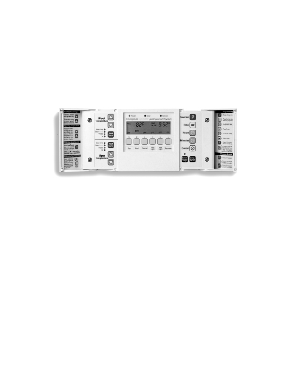
Cp3000 CONTROLLER........................................................................... 22
PROGRAMMING..................................................................................... 27
Lx3000 POWER CENTER....................................................................... 30
VALVE ACTUATORS.............................................................................. 32
SPA-SIDE REMOTE................................................................................ 32
SYSTEM OPTIONS................................................................................. 34
MAINTENANCE............................................................................... 35
PROBLEM SOLVING ...................................................................... 37
WARRANTY .................................................................................... 39
INDEX.............................................................................................. 40
Page 4

Compool Cp3000
Safety Notice
SAFETY NOTICE
IMPORTANT SAFETY INSTRUCTIONS
WHEN INSTALLING AND USING THIS ELECTRICAL EQUIPMENT, BASIC SAFETY PRECAUTIONS
SHOULD ALWAYS BE FOLLOWED, INCLUDING THE FOLLOWING:
• READ AND FOLLOW ALL INSTRUCTIONS.
• WARNING: TO REDUCE THE RISK OF INJUR Y, DO NO T PER MIT CHILDREN TO USE THIS PR ODUCT
UNLESS THEY ARE CLOSELY SUPERVISED AT ALL TIMES.
• WARNING: WATER IN EXCESS OF 100° FAHRENHEIT MAY BE HAZARDOUS TO YOUR HEALTH.
• A TERMINAL BAR (MARKED FOR EQUIPMENT GROUND ONLY) IS LOCATED INSIDE THE HIGH
VOLTAGE COMPAR TMENT OF THE PO WER CENTE R. TO REDUCE THE RISK OF ELECTRIC SHOCK,
THIS TERMINAL MUST BE CONNECTED TO THE GROUNDING MEANS PROVIDED IN THE
ELECTRICAL SUPPLY PANEL WITH A CONTINUOUS C OPPER WIR E EQUIVALENT IN SIZE TO THE
CIRCUIT CONDUCTORS SUPPLYING THIS EQUIPMENT.
• SAVE THESE INSTRUCTIONS .
1
Page 5
Compool Cp3000
Installation
INSTALLATION
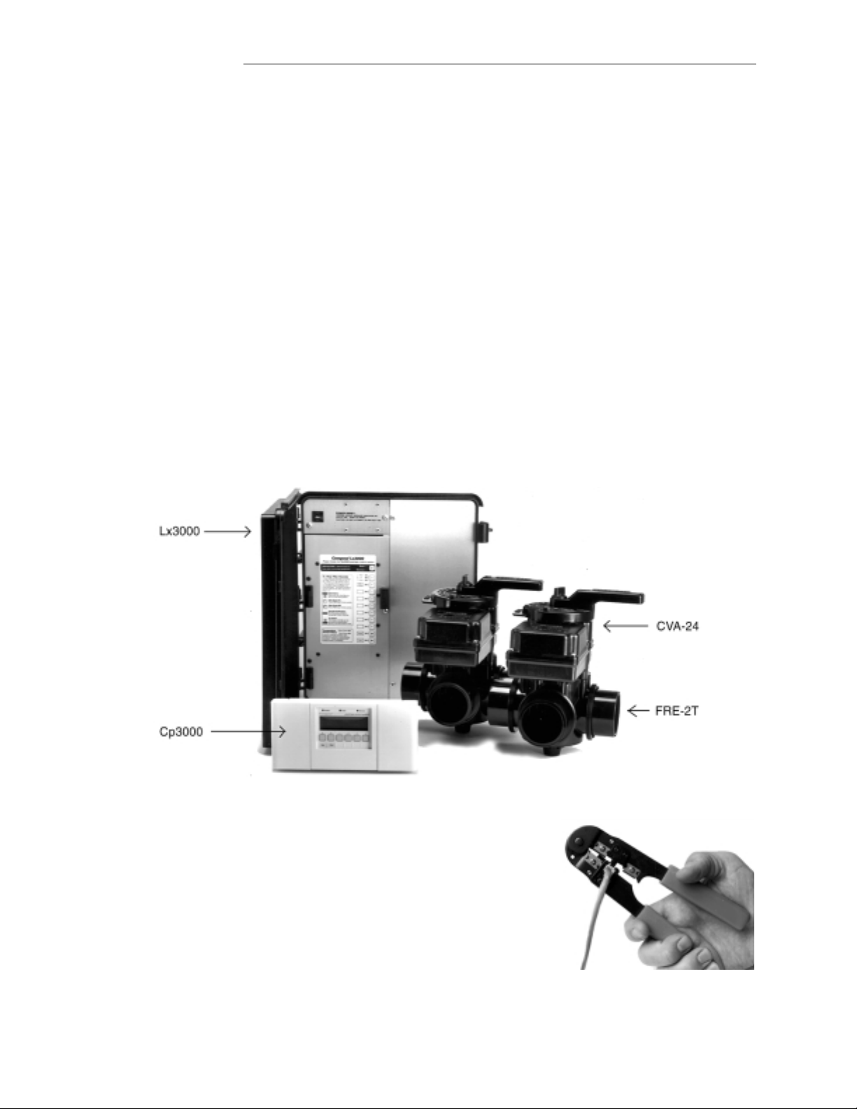
PRODUCT PACKAGE
Open the shipping carton and check the contents. If any items are missing or damaged, contact your dealer
immediately.
The package should include the following items:
• CP-3000 Controller.
• LX-3000 Power C enter.
• CVA-24 Valve Actuators (2 qty).
• FRE-2T 3-Port Freedom Valves (2 qty).
• 6COND Hookup Cable (150 ft.).
• Installation Hardware Kit:
½
” Encloser Screws (4 qty)
”
¼
1
Mounting Screws (3 qty)
Plastic Mounting Anchors (3 qty)
Water Temperature Sensor (w/ Hardware)
2-conduct or Hook-up Cable (25 ft.)
Modular Plugs for Communication Cabl e (3 qty)
Test Cable with Modular Plugs (4 ft.)
SPECIAL TOOLS REQUIRED
1. 3/16” dia. Drill (for mounting Cp3000 Controller).
2. 5/16” dia. Drill (for mounting Water Temperature Sensor).
3. Crimping Tool (model TOOL-6) for mounting Connectors to Hookup Cable.
TOOL-6
2
Page 6
Compool Cp3000
CP-3000
CONTROLLER
INTAE
BLOWER
AIR
SPA
ET
PUMP
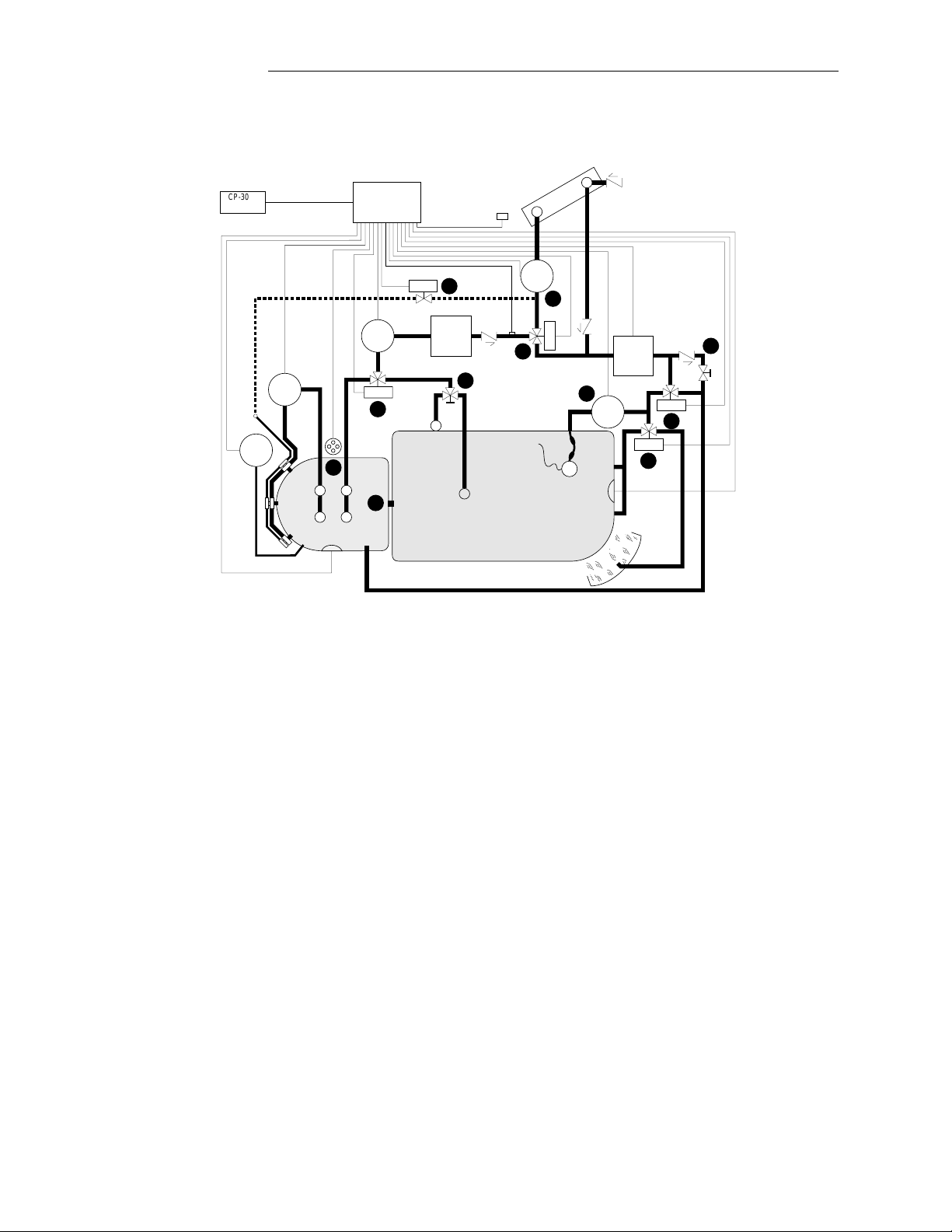
PLUMBING REQUIREMENTS
LX-3000
SERVICE CENTER
HW-5B
REMOTE
SPA-SIDE
FILTER
PUMP
CVA-24
FILTER
SIMMER
SPA POOL
SPA
LIGHT
MAIN
DRAIN
SOLAR
SENSOR
WATER
SOLAR
PUMP
SENSOR
CVA-24
POOL
CLEANER
PUMP
POOL
LIGHT
VACUUM
RELIEF
HEATER
CVA-24
WATERFALL
Installation
CVA-24
Recommended Hydraulic Schematic
Plumb system in accordance with recommended hydraulic schematic, local codes and the following gu idelines.
Bring all lines back to the equipment pad:
1. Spa should be at or above the lev e l of the pool. If spa is attached to pool, provide a dam between the two bodies
of water and allow spa overflow into pool. If spa is not attached to pool, an overflow, sufficient in size to carry
full pump-flow, must be installed between spa and pool.
2. Plumb a 3-port Freedom Valve on the suction-side of the filter pump, so that center port of valve is connected to
the pump inlet. Connect spa suction to one side of Intake Valve, and pool suction to the other side.
3. Plumb a 3-port Freedom Valve on the output-side of the heater, so that return water will enter valve through the
center port. Connect spa retu rn to one port, and pool return to the other.
4. A ¾” spa makeup line (incorporating a ¾” manual gate or ball valve and, for elevated spas, a ¾” check valve)
may be provided to bypass the pool return line. This will enable some of the pool water to cycle through the spa,
thus keeping it chemically balanced with the pool. The manual valve will allow the amount of by pas s to be
adjusted.
5. If an optional Spa-Side Remot e is to be used, install a 6” t o 12” leng th of 1½” Sc h. 40 p vc pipe abo v e w ater le vel
in the spa wall so that the Spa-Side Remote will not be submerged. This can be done by positioning the top of
the 1 ½” pipe ½” below the coping. The pipe should be perpendicular to the spa wall and protrude beyond the
finished surface of the spa. It will be cut back at a later date. Outside the spa, reduce the pipe size down to ½” or
¾” conduit, and run to proposed Lx3000 Power Center l ocation at equipment pad. Use sweep elbows for turns.
The Spa-Side Remote should not be installed until spa constructio n is complete.
3
Page 7

Compool Cp3000
6. For systems which incorporate a skimmer, it is possible to balance the amount of suction between the skimmer
and main drain for maintenance purposes. This is easily accomplished by installing a manual 3-port Freedom
Valve at the suction line. Plumb one port to the skimmer and the other to the main drain.
7. If a “booster pump” type pool cleaner is being used, plumb the pump so that its suction-side is connected to the
pool return, after the heater and as close to t he ground as practical.
8. A motorized 3-port Freedom Valve can be installed to create a waterfall from the return line. This enables a
waterfall effect to occur whenever the filter pump is running, and eliminates the need for a separate pump.
9. For systems which utilize solar panels, plumb the solar feed and return lines between the filter and heater, and
install a motorized 3-port Compool Solar Valve at the solar feed line. Provide a vacuum relief valve at the
highest point of the solar panel array, and a ½ lb. spring check valve at the solar return line. Use Compool Solar
Valve (model SOL-2T), to allow the panels to automatically drain whenever the filter pump is not running.
10. For solar systems with very long plumbing runs, or where panels are i nstalled at a very high elevation (higher
than reasonable head pressure of filter pump), a solar booster pump should be installed at the solar feed line. The
motorized Solar Valve should always be used in conjunction with this pump, except where the vertical elevation
of panels above pool water level exceeds 25 feet.
11. For solar systems with glazed panels, plumb a ½” motorized Solar Drain Valve (model HW-5B) from the solar
feed line, through a check valve, to a zero psi point (such as a jet air intake or pool fill line). Do not connect it to
pump suction. This will enable the panels to automatically drain whenever the solar turns off, even if the filter
pump is still running. This prevents possible scaling of panels and damage from overheating. The Solar Drain
Valve (model HW-5B) should also be used for solar systems which do not facilitate gravity drainage of panels
(i.e.: where solar plumbing crosses the ridge of the roof).
Installation
EQUIPMENT LOCATION
With the exception of the Spa-Side Remote (which is UL Listed for installation right at the tile-line of the spa), all
equipment must be located five feet or more from the water’s edge.
1. Lx3000 Power Center at the equipment site.
2. Cp3000 Controller inside th e house or other weathe r-protected area.
3. CVA-24 Valve Actuator(s) at valve(s) to be motorized.
4. TS-5L Water Temperature Sensor at the filter pump.
5. TS-5L Solar Temperature Sensor at solar panels (where applicable).
6. Spa-Side Remote (optional) at spa wall or decking.
4
Page 8
Compool Cp3000
Installation
HIGH VOLTAGE WIRING
SUB-PANEL
At the equipment site, install an electrical sub-panel with separate breakers for each load. Circuit breakers should be
readily accessible to the pool/spa user, but installed at least 5 feet from the water’s edge.
Note: It is possible to install system without a sub -pa nel.
Lx3000 POWER CENTER
Lx3000
1. Select a convenient location to mount the Lx3000 Power Center. Ensure that the location is greater than 5 feet
from the water’s edge and no further than 15 feet from any motorized valves (otherwise Valve Actuator cables
will need to be extended).
2. Mount the Lx3000 on a flat surface using appropriate screws through the three external mounting points located
on the side of the enclosure.
Caution: Do not drill and mount from inside the enclosure
3. Remove the three service panel screws in right-side of Lx3000 to expose the high voltage compartment.
4. Knock-out the appropriate holes at bottom of enclosure to facilitate conduit mounting. Screw terminals are
provided for high voltage connections.
.
5
Page 9
Compool Cp3000
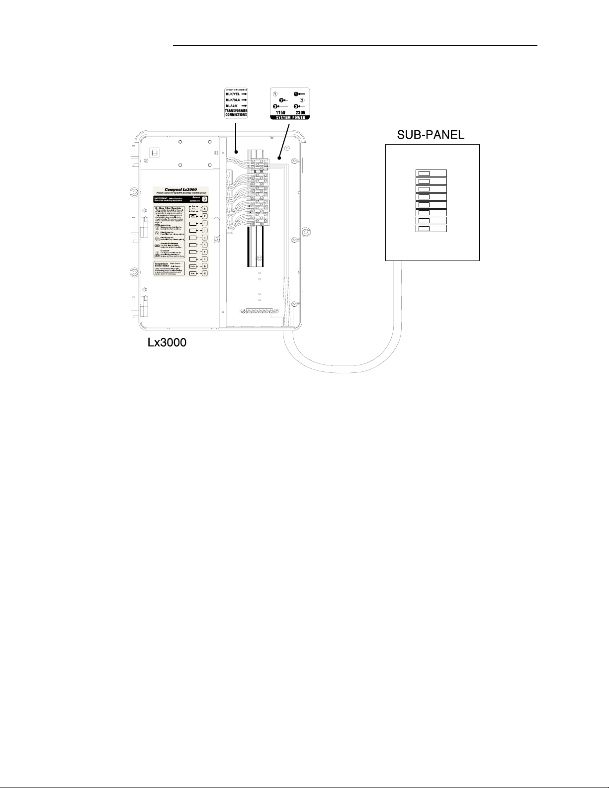
SYSTEM POWER
Installation
1. Provide a separate circuit breaker to power the system. Either 115 or 230 VAC can be used (115 VAC is
preferable). The Cp3000 system draws less than 1 amp.
Caution: Incorrect system wiring will cause permanent damage to the transformer.
2. Verify that the breaker will open all ungrounded supply conductors to comply with section 422-20 of the
Nationa l E lectrical Code, ANSI / NF PA 70-1987.
3. Run appropriate wires from circuit breaker to high voltage compartment of Lx3000, and connect to top terminal
block in accordance with wiring label, which is mark ed “SYSTEM POWER”. The diagram above shows system
wired for 115 volts.
4. For 115 VAC, connect to Screw Terminals #2 and #3.
5. For 230 VAC, connect to Screw Terminals #1 and #3.
6
Page 10
Compool Cp3000
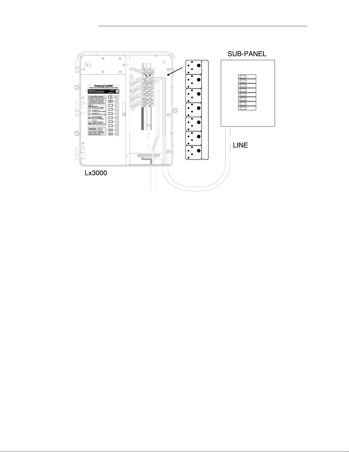
EQUIPMENT POWER
LINE
LOAD
LINE
LOAD
LINE
LOAD
LINE
LOAD
LINE
LOAD
LINE
LOAD
LINE
LOAD
LINE
LOAD
LINE
LOAD
LINE
LOAD
LINE
LOAD
LINE
LOAD
LINE
LOAD
LINE
LOAD
R
R
R3
R
R
R
R
Installation
FULL LOAD 0AMP
LOCKED ROTOR 0AMP
HIGH VOLTAGE RELAYS
1. Install circuit breakers to provide voltage for power relays at R1 through R4. Run appropriate wires from
breakers to high voltage compartment of Lx3000, and connect to LINE 1 and LINE 2 Screw Terminals at each
terminal block.
2. Pumps and other high voltage equipment are connected to LOAD 1 and LOAD 2 terminals. Each individual
terminal block can be wired to operate either 115 or 230 VAC.
3. Connect the high voltage equipment to LOAD 1 and LOAD 2 terminals at each terminal block. The diagram
above shows the high voltage wiring of a 230 VAC filter pump.
4. If the system is to control a pool cleaner pump, it should be connected to the R2 terminal block.
Note: For 115 VAC equipment, only half of the terminal block needs to be used (i.e.: LINE 1 and LOAD 1). The
neutral wire connects directly from the sub panel to the equipment.
ADDING RELAYS
The Cp3000 system comes standard with 4 power relays for activating the Filter Pump, Aux1, Aux2 and Aux3 circuits.
It is possible to install additional Relay Kits (model RLY-LX) to the Lx3000, in order to activate additional equipment.
Install RLY-LX in accordance with instructions provided, and plug relay control wire into Lx3000 circuit board at
appropriate Relay Socket. The Lx3000 Power Center will accommodate a maximum of 7 power relays.
7
Page 11
Compool Cp3000
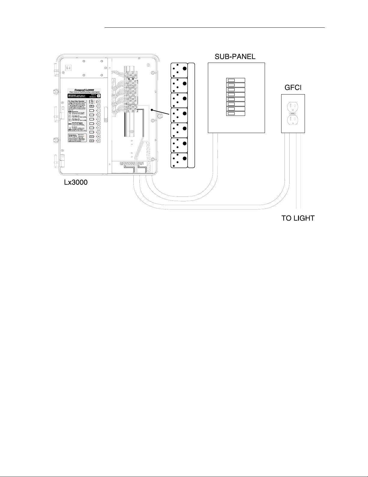
UNDERWATER LIGHTS
LINE
LOAD
LINE
LOAD
LINE
LOAD
LINE
LOAD
LINE
LOAD
LINE
LOAD
LINE
LOAD
LINE
LOAD
LINE
LOAD
LINE
LOAD
LINE
LOAD
LINE
LOAD
LINE
LOAD
LINE
LOAD
R
R
R3
R
R
R
R
Installation
FULL LOAD 0AMP
LOCKED ROTOR 0AMP
HIGH VOLTAGE RELAYS
If the system incorporates 115 Volt Underwater Light(s), you should provide GFCI protection on the load side of the
relay (not the line side) as shown above.
Note: Low voltage lights and fiber optic lights do not require GFCI protection.
1. Run appropriate wire from circuit breaker to LINE 1 of terminal block.
2. Run wire from LOAD 1 and neutral wire from circuit breaker to GFCI.
3. Connect underwater lights to GFCI.
Note: If total load exceeds 500 watts (i.e.: two 400 watt pool lights), provide a jumper wire between LINE 1 and LINE
2 at the terminal block.
8
Page 12
Compool Cp3000
Installation
LOW VOLTAGE WIRING
PC-LX3000
COMPOOL 10890D
GND
SPA
VLV1
WITH
VLV2
ON
FLTR
AUX1
3
AUX2
AUX3
AUX4
AUX5
AUX6
FREEZ PORTHI SPD
ON
SPA
FLTR
3
SOLR
AUX1
ON
SOLAR
MANHT
FEATURES
REM1
REMF
SELECT 4 CIRCUITS
REM3
REM2
S S S 3
REM4
S
VLV2
O
WITH
N
VLV3
COMPOOL 11040A
MOD-VLV3
HLMP
REM5
HBST
REM6
VLV1
VLV2
ACTUATORS
VLV3
AUXILIARY VALVE
TRANSFORMER
CONNECTIONS
INTAKE
VALVE
18
10 24
CAUTION: DO NOT SHORT PINS OF RELAY SOCKETS
HTR
STSSTS+
WTS-
+10
WTS+
TO CP-3000
ACTUATOR ACTUATOR
INT
VLV
RET
VLV
SOL
VLV
SPA
FLTR
AUX1
AUX2
AUX3
AUX4
AUX5
AUX6
EHTR
SOL
PMP
2SPD
GRN
RED
GRN
RED
BLU
RETURN SOLAR
VALVE
RELAY CONNECTIONS
PRESSURE
CONTROL
GAS VALVE
BLU
VALVE
ACTUATOR
HEATER
LIMIT
THERMOSTAT
SOLAR SENSOR
WATER SENSOR
to CP-3000
ON
OFF
RED
YEL
GRN
BLU
ORG
BLK
to SPA-SIDE REMOTE
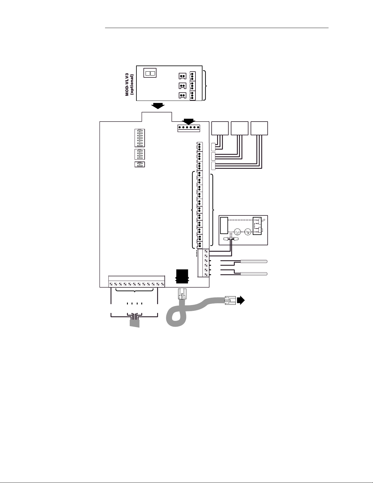
Lx3000 Circuit Board
LOW VOLTAGE CABLES
All low voltage connections are made to the circuit board which is located behind the hinged faceplate in left-side
compartment of Lx3000 Power Center.
150 feet of 6-conductor communication cable (model 6COND), and 25 feet of 2-conductor cable (model 2COND) is
provided with the system. Additional cable is available from your distributor.
Determine lengths of hookup cable required to run from the low voltage compartment of the Lx3000 Power Center to
the various pieces of equipment:
9
Page 13
Compool Cp3000
1. 6-conductor 26 AWG communication cable to the Cp3000 Con troll er. Note: 300’ run maximum. Ca ll Co mpool
for instruction for longer run s. Caution: Always lubricate cable with cable lubricant when pulling through
conduit.
2. 2-conductor 22 AWG cable to the gas heater.
3. 2-conductor 22 AWG cable to the Water Temperature Sensor.
4. 2-conductor 22 AWG cable to optional Solar Temperature Sensor.
5. CVA-24 Valve Actuators are provided with 15 feet of 3-conductor cable. Note: May be extended to a max.
length of 150’ w/ 18 gauge cable (model 3COND/VOR).
6. Optional Spa-Side Remote is provided with necessary cable attached (50’, 100’, 150’, 200’, or 250’ length).
Note: Do not install low voltage and high voltage wires in the same conduit.
Do not install temperature sensor and gas heater wires in the same conduit.
Install cables, using plastic or metallic conduit where cables run underground, through concrete, etc.
MOUNTING THE Cp3000 CONTROLLER
Installation
1. Select a convenient location inside the house or other weather-protected area to mount the Cp3000 Controller.
The overall width of the Controller (with doors open) is 11½”. The location of the 6-conductor communication
cable (on the centerline of the enclosure) should therefore be at least 5¾” from any door jamb, wall corner or
other obstacle. Install the Cp3000 Cont roller at eye level for best viewing of the L CD display.
2. Remove backplate from Controller. Temporarily pull cable through large hole in backplate, and position
backplate on surface of wall. Ensure that backplate is level, and that “TOP” nomenclature is oriented correctly.
Level the backplate and mark the three mounting points on the surface of the wall.
3. With the back plate remov ed from the wall, drill 3/16” d iameter holes at the three points. Insert mo unting anchors
(included) into the three holes.
4. Pull cable through large hole in backplate, and use the three 1¼” screws to mount backplate to wall. Cut off
excess cable, and use crimping tool (m odel TOOL-6) to connect modular plug at each end of cable. See USING
THE CRIMPING TOOL for details.
5. At the Cp3000, insert cable (with modular plug attached) into circuit board at “LINE TO LX” Socket.
10
Page 14

Compool Cp3000
6. Use the four ½” screws (included) to mount Controller to the backplate.
7. At the Lx3000, insert cable (with modular plug attached) into circuit board at “to CP-3000” Socket.
USING THE CRIMPING TOOL
TOOL-6
1. Use Cutter to prepare cable end. Make sure that cable is cut squarely (not diagonally).
Installation
2. Insert the cable between the Stripper blades of the tool until it touches the stop. Squeeze the handles and pull the
tool, making sure that the cable stays perpendicular to it. If this is done correctly, the outer jacket of the cable
will be removed without damaging the insulation on the individual conductors.
3. Plug a modular connector into the holder so that the gold contacts face the Crimper.
4. Orient the prepared cable so that the blue conductor is closest to the tool handles, and insert cable into connecto r.
Make sure the wires go all the way to the back of the connector.
5. Squeeze the handles firmly
Note: It is important that the orientation (blue conductor closest to tool handles) is identical at each end of the cable.
CVA-24 VALVE ACTUATORS
to set the contacts and secure the cable.
CVA-24
1. Remove knob, handle and four screws from cap of valve(s) to be motorized, and use the four mounting screws
provided to mount Valve Actuator(s) to valve(s).
2. Run cable(s) to low voltage compartment of Lx3000 Power Center.
3. At the Lx3000, plug cable(s) into appropriate Valve Socket on circuit board:
11
Page 15

Compool Cp3000
• Plug Intake (suction) Valve to INT VLV Socket.
• Plug Return Valve to RET VLV Socket.
• Plug Optional Solar Valve (if applicable) to SOL VLV Socket.
Note: To control additional valve actuators, see AUXILIARY VALVE ACTUATORS for details.
GAS HEATER CONNECTIONS
Installation
Follow these instructions to connect a gas heater (millivolt or electronic-ignition) or propane heater:
1. Cut sufficient 2-conductor cable (25 ft. is included with Accessory Kit) to run between the heater and the
Lx3000.
2. Inside the heater, interrupt wire between thermostat and pressure switch (where fireman’s switch is typically
connected), and interconnect with 2-conductor cable us ing wire nuts. Do not discon nect or by pass the thermostat
or any safety switches.
3. Run cable to low voltage compartment of Lx3000. At the Lx3000, strip insulation ¼” and connect to circuit
board at the two HTR Screw Terminals.
4. Turn the heater switch to ON (or High) and set thermostat(s ) to maximum.
WATER TEMPERATURE SENSOR
1. Select a convenient location to mount the Temperature Sensor (model TS-5L) between the pump and filter.
2. Drill a 5/16” diameter hole in the pipe, and insert the Sensor. Position the hose clamp over the Sensor, and gently
tighten around pipe. Caution: Overtightening of clamp can cause deformation of O-ring seal.
3. Use the remainder of the 2-conductor cable (provided with Accessory Kit) to run between Sensor location and
low voltage compartment of Lx3000 Power Center.
4. At the Sensor, p ay attention to color -coding of wire s (green wire connects to green; red wire connects to red), an d
use crimp connectors (included) to provide waterproof connections. Before making connections, shorten sens or
12
Page 16

Compool Cp3000
leads to about 6”. Do not strip wires. Push the 2 wires to be connected into the small holes at one end of the
connector, and squeeze the connector with a pair of pliers. 2 extra connectors are included.
5. At the Lx3000, connect Sensor cable to circuit board at WTS- and WTS+ Screw Terminals in accordance with
wiring diagram located inside Lx3000 door. Pay attention to color-coding of wires (green wire connects to
WTS- and red wire connects to WTS+).
Note: Infield calibration of temperature sensor(s) is required. See CALIBRATING TEMPERATURE SENSORS for
details.
Installation
13
Page 17

Compool Cp3000
Installation
SYSTEM OPTIONS
SPA-SIDE REMOTE
SS4-100W
The optional Spa-Side Remote (model SS4-100W) is a double-insulated device which is UL Listed for installation
within 5 feet of the water’s edge. It is typically installed at the tile- line on th e spa wall (abov e water level), or i n the
deck within arm’s reach of the spa. If the Spa-Side Remote is to be installed into the wall of a gunite spa, provision
must be made while the spa is being plumbed (See PLUMBING REQUIREMENTS for details):
1. When the spa construction is completed, cut back the 1½” dia. pvc pipe receptacle flush with the spa wall finish
or surface of deck.
2. Screw Mounting Adapter onto Spa-Side Remot e, and finger-tighten. Caution: Do not use wrench.
3. Thread Spa-Side Remote cable through conduit to low-voltage compartment of Lx3000.
4. Carefully glue Mounting Adapter into 1½” pvc receptacle using pvc cement. For aesthetic purposes, it is
suggested that the Spa-Side Remote be installed with Red button in the 12 o’clock position.
5. At the Lx3000, identify the 6-conductor cable from the Spa-Side Remote, and cutoff excess cable as necessary.
Strip insulation of each conductor ¼" and connect to appropriate Screw Terminals at bottom of circuit board in
accordance with wiring diagram:
6. Connect Black wire (Switch Common) to GND Screw Terminal.
7. Connect Orange (Status Lamp) to HLMP Screw Terminal.
8. Determine which 4 of the following circuits you wish to control from within the spa, and connect Red (Red
button), Yellow (Yellow button), Green (Green button) and Blue (Blue button) wires to the appropriate Screw
Terminals (see LX3000 CIRCUIT BOARD for details):
• SPA Rotates intake and return valves, and activates filter pump and heater.
• REMF Activates filter pump (normally not used).
• REM1 Activates auxiliary 1 equipment (such as pool cleaner).
• REM2 Activates auxiliary 2 equipment (such as pool light).
• REM3 Activates auxiliary 3 equipment (such as spa light).
• REM4 Activates auxiliary 4 equipment (such as fountain or waterfall).
• REM5 Activates auxiliary 5 equipment (such as jet pump).
• REM6 Activates auxiliary 6 equipment (such as air blower).
• HBST Enables spa heating for a five minute period.
For Spa-Side control of more than 4 pieces of equipment, a second Spa-Side Remote may be installed.
14
Page 18

Compool Cp3000
Installation
A set of adhesive labels is provided for custom identification of individual Spa-Side Remote buttons. Use a pair of
fine-tip tweezers to carefully adhere the appropriate label at each button.
2-SPEED FILTER PUMP CONTROL
If the system is equipped with a 2-Speed Filter Pump, a 2-Speed Filter Pump Relay Kit (model RLY-LXD) s hou ld be
installed at the Power Center in accordance with instructions provided.
There are three ways to configure the 2-Speed Filter Pump control:
1. Automatic configuration:
The system will run the filter pump in “low sp eed” durin g norm al operati on, but will au tomati cally sw itch th e pump
to “high speed” for 5 minutes whenever the filter pump turns on.
It is additionally possible to activate the pump in “high speed” whenever the spa, heater, solar and/or Aux1 (pool
cleaner) is running. To enable the pump to run in “high speed” during these conditions, it is necessary to adjust the 4position HI SPD Program Switch, which is located at top center of Lx3000 circuit board. Use the corner of a small
screwdriver or other blunt instrument to slide the appropr iate Switch(es) to the ON position:
Switch #1: Enables high speed when spa is running.
Switch #2: Enables high speed when heater is running.
Switch #3: Enables high speed when solar system is running.
Switch #4: Enables high speed when Aux1 (pool cleaner) is running.
Connect RLY-LXD relay control wire into 2SPD Relay Socket.
2. Manual configuration:
The system will run the filter pump in “low speed” during normal operation, but will switch the pump to “high speed”
when an Auxiliary Circuit is activated.
Select an Auxiliary Circuit (Aux1 - Aux6), and connect RLY-LXD control wire into the appropriate Relay Socket.
3. Combined configuration:
The “high speed” is controlled by an Auxiliary Circuit an d the HI-SPD Program Switch. Use Dual Circuit Relay
Adapter (model CRA-LX) to connect RLY- LXD relay control wire into an Auxiliary Relay Socket and into 2SPD
Relay Socket.
AUXILIARY VALVE ACTUATORS
VLV1
WITH
VLV2
VLV2
12
O
WITH
N
VLV3
COMPOOL 11040A
MOD-VLV3
CONTROL JUMPER
SOCKETS
VLV1
VLV2
VLV3
ACTUATORS
AUXILIARY VALVE
MOD-VLV3
It is possible to add Valve Actuators ( model CVA-24) to the system to motorize two-port or three-port valves for
custom hydraulic features (such as a pool cleaner, fountain, waterfall, etc.). A total of three Valve Actuators may be
added. Valve Actuators can be activated from any Circuit.
1. Install Auxiliary Valve Module (model MOD-VLV3) at the Lx3000 low voltage compartment in accordance with
instructions provided.
15
Page 19

Compool Cp3000
2. Remove knob, handle and four screws from cap of valve(s) to be motorized, and use the four mounting screws
provided to mount Valve Actuator(s) to valve(s).
3. Run cable from Valve Actuator to Lx3000 low voltage compartment.
4. Plug end of Valve Actuator cable(s) into appropriate Valve Socket(s) on the MOD-VLV3 circuit board (VLV1,
VLV2, or VLV3).
5. Locate Wiring Harnesses, which are provided with the Valve Module.
6. Select which Circuit(s) you wish to use for activating Valve Actuator(s). Each Circuit will require a Wiring
Harness.
7. Plug one end of Wiring Harness into Lx3000 circuit board at the appropriate Relay Socket.
8. Plug other end of Wiring Harness into MOD-VLV3 at appropriate CONTROL JUMPERS Socket.
9. To combine the operation of VLV1 with VLV2 and/or VLV 2 with VLV3, adjust the COMBINED VALVES
Program Switch (at upper left-side of MOD-VLV3) accordingly.
HIGH VOLTAGE THERMOSTAT HEATER
For systems which utilize a high voltage thermostat, such as an oil fired heater, electric heater, or heat pump, a Relay
Kit (model RLY-LX) should be added.
Installation
1. Install RLY-LX at the Lx3000 in accordance with instructions provided, and plug relay control wire onto circuit
board at EHTR Relay Socket. The relay will close whenever the Cp3000 is calling for heat.
2. Splice thermostat wiring inside heater and run wires of sufficient gauge to Line 1 and Load 1 of RLY-LX relay
terminal block.
FREEZE PROTECTION SETTINGS
It is possible to automatically circulate water through the equipment whenever the temperature drops to 35° F. This
will protect the equipment against possible freeze damage.
The Control System uses the Water Temperature Sensor to detect freezing conditions, so a separate Freeze Sensor is
not required.
It is, however, necessary to adjust the 7-position FREEZ PROT Program Switch, which is located at top center of
Lx3000 circuit board. Determine which e quipm ent yo u wou ld like to activate during freezing conditions, and us e the
corner of a small screwdriver or other blunt instrument to slide the appropriate Switch (es) to the ON position:
Switch #1: Activates FLTR (filter pump) during freezing conditions.
Switch #2: Activates AUX1 during freezing conditions.
Switch #3: Activates AUX2 during freezing conditions.
Switch #4: Activates AUX3 during freezing conditions.
Switch #5: Activates AUX4 during freezing conditions.
Switch #6: Activates AUX5 during freezing conditions.
Switch #7: Activates AUX6 during freezing conditions.
When Freeze Mode starts, the Cp3000 display will indicate “FRZ” and turn on any circuit that has been selected by
the FREEZ PROT Program Switch. Equipment key icons will not show “ON” if activated by the Freeze Mode.
Switch #1 additionally cycles the pool and spa for 15 minutes each. The Freeze Mode lasts for 30 minutes. Pressing
16
Page 20

Compool Cp3000
any of the equipment keys on the Cp3000 controller will deactivate the Freeze Mode.
SOLAR TEMPERATURE SENSOR
If the system incorporates solar, install an optional Temperature Sensor (model TS-5L) at the solar panel array.
1. Adjust the 2-position Program Switch, which is located at top center of Lx3000 circuit board. Use the corner of
a small screwdriver or other blunt instrument to slide Switch #1 (SOLAR) to the ON position.
2. Discard clamp (included with TS-5L). Do not drill hole and clamp sensor into solar pipe. For unglazed
panels, fasten Sensor to surface next to solar panels. Do not bolt directly to panel. For glazed panels, suspend
Sensor between collector and glazing.
3. Provide 2-conductor cable between Solar Sensor and low voltage compartment of Lx3000 Power Center.
4. At the Sensor, p ay attention to color -coding of wire s (green wire connects to green; red wire connects to red), an d
use crimp connectors (included) to provide waterproof connections. Before making connections, shorten sens or
leads to about 6”. Do not strip wires. Push the 2 wires to be connected into the small holes at one end of the
connector, and squeeze the cylinder with a pair of pliers. 2 additional connectors are included. It is
recommended to tape connections and wiring to prevent possible damage from UV radiation. Be sure to keep
wires separated.
Installation
5. At the Lx3000, connect cable from Solar Sensor to circuit board at STS- and STS+ Screw Terminals. Pay
attention to color-coding of wires (green wire connects to STS- and red wire connects to STS+).
Note: Infield calibration of temperature sensors is required. See CALIBRATING TEMPERATURE SENSORS for
details.
SOLAR BOOSTER PUMP CONTROL
If a solar booster pump is being used, install a Relay Kit (model RLY-LX) at the Lx3000 in accordance with
instructions provided, and plug onto circuit board at SOL PMP Relay Socket.
17
Page 21

Compool Cp3000
Cp3000 CIRCUIT BOARD
COMPOOL 10881A
PART No PC-CP3000
Installation
S1
3
2
1
LINE
TO LX
S2
CS
FS
FC
CD
FD
ON
RESET
NORMAL
To enable the following options, refer to the Cp3000 circuit board diagram shown above.
SPA WATERFALL CONTROL SWITCH
For systems where spa water level is higher than that of the pool, it is possible to use Circuit #2 to rotate the return
valve to spa return position, thus creating an overflow (waterfall effect) from the spa into the pool. This effect will
cease during spa circulation or pool cleaner operation.
To enable this feature, it is necessary to adjust the 3-position S1 Program Switch, which is located at top right-side of
Cp3000 circuit board. Using the corner of a small screwdriver or other blunt instrument, slide Switch #3 to the ON
position.
CUSTOM CLOCK OPTIONS
The standard Cp3000 Controller is provided with the appropriate equipment interlock and safety delays, assuming that
Aux1 Circuit is being used to activate a pool cleaner pump. It is, however, possible to eliminate the interlocks and
delays for custom applications (such as where there is no pool cleaner).
To achieve this, it is necessary to modify the 5-position S2 Program Switch which is located at center right-side of the
Cp3000 circuit board. Use the corner of a small screwdriver or other blunt instrument to slide the appropriate
Switch(es) to the OFF position:
Switch #1: Filter Pump Off Delay (fireman’s switch).
Switch #2: Aux1 (Pool Cleaner) On Delay.
Switch #3: Aux1 Pool Cleaner/Filter Interlock.
Switch #4: Spa/Filter Interlock.
Switch #5: Spa/Aux1 (Pool Cleaner) Interlock.
If the control system does not incorporate a pool cleaner pump, Switches #2, #3 and #5 can be turned OFF, and the
Aux1 Circuit can be used for another auxiliary function.
SPA-SIDE COUNTDOWN TIMER
A built in 30 minute countdown timer is set at the factory for Auxiliary Circuits 5 and 6. These circuits usually operate
a jet pump and blower, and are controlled by the Spa-Side Remote.
To disable this feature, it is necessary to modify the 3-position S1 Program Switch which is located at center right-side
of the Cp3000 circuit board. Use the corner of a small screwdriver or other blunt instrument to slide the appropriate
Switch(es) to the OFF position. Switch #1 will actuate Aux6; and Switch #2 will actuate Aux5.
18
Page 22

Compool Cp3000
Installation
SYSTEM START-UP
1. Turn system power on.
2. At the heater, m ake sure that the switch is tur ned to the ON, High or Spa position, and that the temperature dial is
turned to the highest setting.
3. At the Lx3000 Power Center, press the Auto/Service Key to switch the System to “Service” mode. Press the #S
Key to Spa mode, and check that Valve Actuators have rotated to spa positions. If either valve is 180° out of
phase, flip toggle switch on rear of Valve Actuator from ON1 to ON2 position.
4. Press the remaining Equipment Service Keys (#P, #1, #2, #3, #4, #5 and #6) to verify that corresponding
equipment is being activated.
5. Press the Heater Key, and verify that the heater is firing (filter pump must be on and pumping).
6. If solar system is installed, verify program switch on the Lx3000 circuit board SOLAR is in the ON position.
The Cp3000 system will only recognize the solar installation if this switch is ON (see SOLAR SENSOR for
details).
7. Press the Solar Key , and check that the Solar Valve (if applicable) has rotated to solar position. If it is 180° out of
phase, flip toggle switch on rear of Valve Actuator from ON1 to ON2 position.
8. Check that neither Temperature Sensor Status lamps are illuminated. If a lamp has turned on, check wiring
connections to the appropriate Sensor.
9. After the equipment operation has been tested from the Lx3000, press Auto/Service Key to return System to
“Auto” mode.
10. At the Cp3000 Controller, press each Equipment Key (#S, #P, #1, #2, #3 and #4), and check that appropriate
equipment is being activated. Note: If the Auto/Service Key at the Lx3000 has inadvertently been left in the
“Service” mode, the Service status lamp will illuminate at the Cp3000 Controller.
11. A set of adhesive labels is provided for custom identification of individual circuits. Use a pair of fine-tip
tweezers to adhere the appropriate label adjacent to the Equipm ent Key at the Cp3000 Controller and Lx3000
Power Center. A set of labels is also provided for custom identification of the buttons at the optional Spa-Side
Remote.
19
Page 23

Compool Cp3000
CALIBRATING TEMPERATURE SENSORS
The following infield calibration is required for the Temperature Sensor(s):
Installation
1. Use a thermometer to verify pool temperature.
2. Use a thermometer to verify solar temperature if applicable.
3. At the Cp3000 Controller, turn on the Pool and let it run for a few minutes.
4. Press the Program Key.
5. Press the Pool Heat Source Key. ADJ 1 will appear on the Display.
6. Use the Pool Temperature Keys to enter the temperature verified in Step 1.
7. Press the Pool Heat Source Key again. If the system incorporates a Solar Temperature Sensor, ADJ 2 will now
appear on the Display. Use the Pool Temperature Keys to enter the temperature verified in step 2.
8. Press the Pool Heat Source Key once more to return the Display to the normal operating mode.
20
Page 24

Compool Cp3000
Operating Instructions
OPERATING INSTRUCTION S
INTRODUCTION
The Cp3000 is an electronic control system which is designed to coordinate and oper ate all of the equipment associated
with your swimming pool and spa. The system is comprised of three principal components:
• Cp3000 Controller.
• Two CVA-24 Valve Actuators.
• Lx3000 Power Center.
The Controller automatically controls and monitors the timing of all your pool and spa equipment, and the temper ature
of your pool and spa; the Valve Actuators switch the filter and heater from pool to spa; and the Power Center provides
easy maintenance for your Pool Serv iceperson.
Additionally, the Control System incorporates important safety features which protect your pool equipment from
accidental damage. Your system may also include a Spa-Side Remote and other options which further add to the
convenience, safety, and economy of operating your pool and spa equipment.
Note: It is not recommended to use the Cp3000 system to control a pool cover.
SAFETY FEATURES
HEATER PROTECTION
A built-in electronic delay circuit automatically runs the filter pump for an additional 5 minutes whenever the system
is turned off. This feature enables the heater to cool down, so that the heat exchanger and plumbing are not damaged
from overheating.
If the filter pump is being turned off after using the spa and the pool was not previously on, the motorized valves will
remain in the “spa circulation” position during t his 5 m inute “heater cool down” cycle. Th is prevents the poss ibility
of any cold water being cycled from the pool into the spa during this period of time.
21
Page 25

Compool Cp3000
POOL CLEANER PROTECTION
If your system incorporates a pool cleaner, it may have been plumbed in conjunction with the filter pump so that it
must have water circulation in order to operate. The Cp3000 incorporates the following protection features against
accidental pump damage, which can occur if there is no water circulation:
1. The filter pump will automatically switch to pool circulation whenever the pool cleaner is running.
2. Whenever the pool cleaner is turned on, a built-in electronic delay circuit will prevent it from running until 5
minutes of filtration have passed. This protects the cleaner pump from possible damage caused by air which may
have entered the plumbing since the system was last used.
3. Your pool cleaner will automatically be switched off whenever water is being circulated to the spa.
4. If your system incorporates solar, the pool cleaner will automatically be disabled for a period of 5 minutes
whenever the solar system turns on. This protects the pool cleaner from possible damage caused by residual air
within the solar panels.
Note: If your system incorporates a pool cleaner, your Pool Builder will have labeled Equipment Key #1 (Aux1
circuit) at the Cp3000 Controller for switching this equipment.
OVERRIDING THE SAFETY DELAY CIRCUITS
For testing and servicing purposes only, it is possible to override any of the safety delay circuits by pushing the
CANCEL Key, which is located behind the right-side door of the Cp3000 Controller.
Operating Instructions
BATTERY BACK-UP
In case of a power failure, a long-life battery automatically maintains the program and clock functions of your Control
System. This safeguards against the equipm ent operating erratically once power has b een restored, and also eliminates
the need to reprogram whenever there is a power failure.
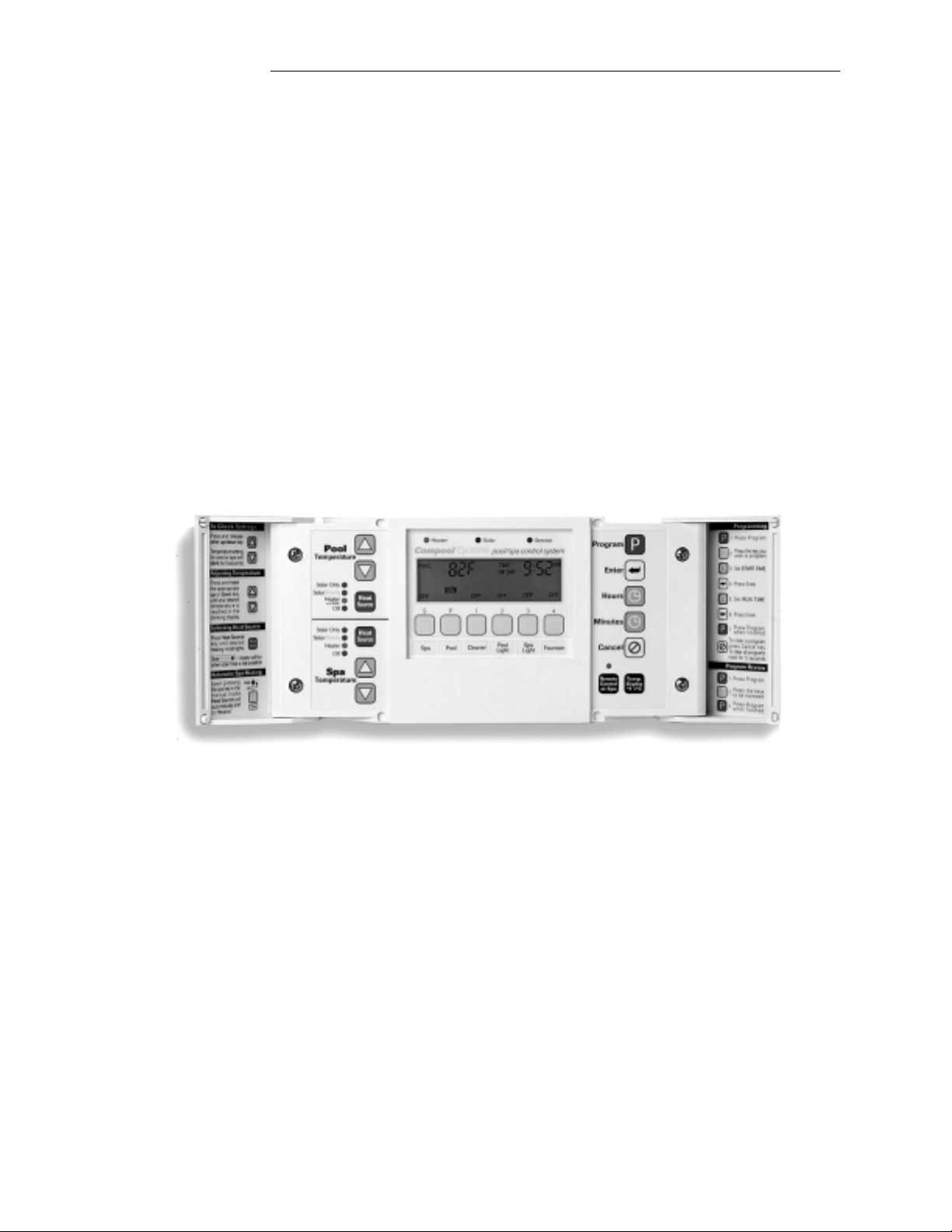
Cp3000 CONTROLLER
Installed in a convenient location inside your house, the Cp3000 Controller gives you fingertip control of all the
equipment associated with your swimming pool and spa.
EQUIPMENT STATUS LAMPS
There are three Equipment Status Lamps located above the Display:
22
Page 26

Compool Cp3000
Heater:
Indicates whenever the heater is on.
Solar:
Indicates whenever the solar system (if applicable) is running.
Service:
Indicates whenever the equipment is being op erated from the equipment site (i.e. the Auto/Service Key at the Lx3000
Power Center is in the Service position).
DISPLAY
When the system is in the “normal operating mode”, the TIME O F DAY and the ON/OFF Equipment Status of each
of the six Equipment Keys will be displayed. If the pool or spa is running, the actual POOL or SPA temperature will
be displayed.
Operating Instructions
EQUIPMENT KEYS
Six Equipment Keys are provided for activating the various pieces of equipment. Your Pool Builder should have
custom-labeled each Key for your specific application. To switch equipment ON or OFF, simply press the appropriate
Equipment Key once. An audible beep will sound indicating the Equipment Key has been pressed.
Equipment Status is indicated on the Display immediately above each Equipment Key:
• A solid ON indicates that the equipment has been activated.
• A solid OFF indicates that the equipment is switched off.
• A blinking ON indicates that the equipment will activate after its 5 minute safety delay has expired.
• A blinking OFF indicates that the equipment will turn off after its 5 minute safety delay has expired.
Key #S:
Rotates valves to spa circulation and activates filter pump. Activates spa heating. Disables pool cleaner (if applicable).
Key #P:
Activates filter pump and circulates water for pool filtration. Enables pool heating.
Key #1:
Activates pool cleaner (if applicable) after 5 minute safety delay. Automatically activates pool filtration if Key #P is
not already turned ON.
Note: If system does not incorporate a pool cleaner, Key #1 will activate auxiliary equipment (such as lighting).
23
Page 27

Compool Cp3000
Key #2:
Activates auxiliary equipment (such as a pool light).
Key #3:
Activates auxiliary equipment (such as a spa light).
Key #4:
Activates auxiliary equipment (such as a fountain).
USING YOUR SPA
To turn your Spa ON, simply press Key #S. The motorized valves will rotate to “spa circulation” position, the filter
pump will turn on, and the heater will heat the spa to the pre-selected spa temperature. The Display will indicate the
precise spa temperature, and the Heater Status Lamp will indicate whether the spa is heating or not.
To turn your Spa OFF, press Key #S. The heater will automatically shut- off. Provided the sy st em is not resum ing a
preset pool circulation cycle, the filter pump will continue to circulate the spa water for its 5 minutes safety d elay in
order to cool down the system. After 5 minutes, the filter pum p will shut- off and the mot orized valves will r eturn to
pool circula t ion position.
Note: Some heaters do not require a cool down cycle, so this safety feature may be turned off. See CUSTOM CLOCK
OPTIONS for details.
Operating Instructions
It is possible to program the Spa, so it will automatically shut-off after a predetermined length of time. See
COUNTDOWN TIMER PROGRAM for details.
POOL AND SPA HEATING
Concealed behind the left-side door are separate Temperature Controls for the Pool and Spa. Each control incorporates
a Heat Source Key, two Temperature Keys, and four Heat Source Lamps.
HEAT SOURCE KEY
It is possible to heat your pool and spa us ing con ventional heat, s olar energ y ( if app licable), o r a co mbin ation of bo th.
Pressing the Heat Source Key will toggle through the different heating options, as follows:
• Off: Allows no heating.
24
Page 28

Compool Cp3000
• Heater: Allows heating with gas or electric heater only.
• Solar Priority: Allows heating with solar, but automatically switches to conventional heating when solar energy
is unavailable. If your system does not incorporate solar, the Solar Priority and Solar Only options will not be
available.
• Solar Only: Allows heating with solar only when solar heat is available. If your system does not incorporate
solar, the Solar Priority and Solar Only options will not be available.
Note1: Pressing the Heat Source Keys(s) does not activate the heater and solar system. Heating can only occur when
the pool or spa is being circulated and desired temperature settings have not yet been satisfied.
Note2: For added convenience, whenever the spa is manually activated (from either th e Cp3000 Controller or the SpaSide Remote), the Spa Heat Source Lamp will automatically switch to “Heat er” and heating will begin. Tur ning the
spa off will return Spa Heat Source Lamp to its previous position.
TEMPERATURE KEYS
The UP and DOWN Temperature Keys are used to prese t your d esired water temperature. As long as the Heat Sou rce
Key(s) are not in the OFF position, the pool and spa will heat up to the preset temperature(s) whenever pool or spa is
being circulated.
Operating Instructions
CHECKING DESIRED WATER TEMPERATURE SETTING
To check the pool and spa temperature settings, press the appropriate (Pool or Spa) Temperature Key once. The preset
temperature will blink on the Display for 5 seconds.
SETTING DESIRED WATER TEMPERATURE
To adjust the pool and spa temperature settings, press the appropriate (Pool or Spa) Temperature Key until the Display
indicates your desired water temperature. After 5 seconds, the Display will automatically return to its original
condition. Temperature settings can be adjusted in the normal operating mode only.
FAHRENHEIT/CELSIUS TEMPERATURE DISPLAY
The “Temp. Display” Key (located behind right-side door) will enable you to display temperatures in either Fahr enheit
or Celsius.
25
Page 29

Compool Cp3000
SETTING THE CLOCK
To set the Display to the correct TIME OF DAY, press the Hours and Minutes Keys (located behind the right-side door
of the Cp3000 Controller). Pay attention to the AM/PM symbols on the Display.
Operating Instructions
26
Page 30

Compool Cp3000
Operating Instructions
PROGRAMMING
DAILY EQUIPMENT OPERATING CYCLES
Behind the right-side door are Keys for programming the daily operating cycles of the equipment. Programming is a
“set and forget” procedure, which is normally implemented by your Pool Builder at the completion of the installation.
Most systems only require that you program the pool filtration cycles (Key #P) and, in some cases, pool cleaning cycles
(Key #1). However, it is possible to program equipment connected to any of the six Equipment Keys at the Cp3000
Controller.
Before commencing programming, you will need to determine at what time yo u would like t he equipment to turn on
(START TIME), and for how long you would like each piece of equipment to run (RUN TIME). Your Pool Builder
will be able to recommend the appropriate filtration and cleaning cycles for your pool and spa.
BASIC PROGRAM
The following example programs the Pool Filter Pump to run eight hours every day:
1. Press the Program Key to start the program.
2. Press the Equipment Key “P” to program the pool.
3. Press the Hours Key to set the START TIME (example 8:00 A.M.)
4. Press the Enter Key to save the STA RT TIME.
5. Press the Hours Key to set the RUN TIME (example 8 Hours).
6. Press the Enter Key to save the RUN TIME.
7. Press the Program Key to return to the normal operating mode.
➥
➥
27
Page 31

Compool Cp3000
MULTIPLE PROGRAMS
A total of four operating cycles may be programmed each piece of equipment. To program multiple operating cycles,
follow steps 1 to 6 on the BASIC PROGRAM, and then press the Equipment Key a second time. The display will
indicate PROG 2, plus a blinking START TIME. Repeat steps 3 to 6 to program a second START TIME and RUN
TIME. If additional cycles are desired, repeat this procedure for PROG 3 and PROG 4.
Note: If only one operating cycle is programmed, PROG will be displayed. PROG 1 indicates that multiple operating
cycles have been programmed for that equipment.
COUNTDOWN TIMER PRO GRAM
It is possible to program a “COUNTDOWN TIMER” for any piece of equipment, so that, whenever that equipment is
activated manually it will run for its predetermined length of time and then automatically shut-off. This energy saving
program is particularly useful for programming the Spa to shut-off after a few hours.
The COUNTDOWN TIMER is programmed by setting the START TIME to 0:00 hours and setting the RUN TIME
to the desired time you wish the equipment to run. The RUN TIME can be set (in 10 minute increments) for any length
of time fr om 10 mi nutes (0 :10) t o 23 ho urs and 50 minu tes (23 :50). T his fea ture may be com bined with an y other
program (i.e. if PROG 1 is already used, use PROG 2, PROG 3, or PROG 4).
Note: If there is no COUNTDOWN TIMER program, the equipment will automatically shut-off after 12 hours.
Operating Instructions
The following example programs the Spa to shut-off after two hours:
➥
➥
1. Press the Program Key to start the program.
2. Press the Equipment Key “S” to program the spa.
3. Press the Enter Key to save the START TIME at 0:00.
4. Press the Hours Key to set the RUN TIME (example 2 hours) .
5. Press the Enter Key to save the RUN TIME.
6. Press the Program Key to return to the normal operating mode.
28
Page 32

Compool Cp3000
ONCE ONLY PROGRAM
It is possible to program a “ONCE ONLY” program for any of the Equipment Keys on the Cp3000. When a ONCE
ONLY program is executed, it is erased automatically. This feature is useful to program the Spa in advance so it will
be ready for use within a 24 hour period. With this convenient feature, there is no need to “de-program” the spa after
use. The ONCE ONLY program simply erases itself.
Follow the standard programming procedure to Step 3, enter a START TIME only. Do not enter a RUN TIME (RUN
TIME should indicate 0:00). Press Program Key to return to the normal operating mode.
This feature may be combined with any program (i.e. if PROG 1 is already u sed, us e PROG 2, PROG 3, or PROG 4).
REVIEWING THE PROGRAM(S)
To review the programmed operating cycle(s) of any piece of equipment:
1. Press the Program Key. The Display will indicate PROG (to show that Clock is in programming mode), plus a
row of blinking icons located immediately above the six Equipment Keys.
2. Press the appropriate Equipment Key (either #S, #P, #1, #2, #3 or #4). The icon above the Equipment Key will
stop blinking, the remaining icons will disappear, and the programmed START TIME (blinking) and R UN TIME
will be displayed.
Operating Instructions
3. The appearance of PR OG 1 on the Display indicates that there is more th an one o perating c ycle pr ogr ammed f or
this equipment. To review additional program(s), press Equipment Key again.
4. If you wish to review the operating cycle(s) of another piece of equipment, return to Step 2 (i.e. press the
appropriate Equipment Key).
5. When you hav e f inished r e viewing the various pieces of equipment, press the Program K e y to return the Clock to
normal operating mode.
CANCELING PROGRAM(S)
It is possible to cancel one or more of the programmed operating cycles:
1. Press the Program Key. The Display will indicate PROG (to show that Clock is in programming mode), plus a
row of blinking icons located immediately above the six Equipment Keys.
2. Press the appropriate Equipment Key (either #S, #P, #1, #2, #3 or #4). The icon above the Equipment Key will
stop blinking, the remaining icons will disappear, and the programmed START TIME (blinking) and R UN TIME
will be displayed.
3. Press the Cancel Key. The Display will indicate a START TIME (blinking) of 0:00 and a RUN TIME of 0:00.
4. If you wish to cancel additional program(s), return to Step 2 (i.e. press the appropriate Equipment Key).
5. If you wish to cancel all of the programs, press and hold down the Cancel Key for 5 seconds. After 5 seconds, a
continuous alarm will sound (until you release the Cancel Key), indicating that all of the programming has been
erased.
29
Page 33

Compool Cp3000
Operating Instructions
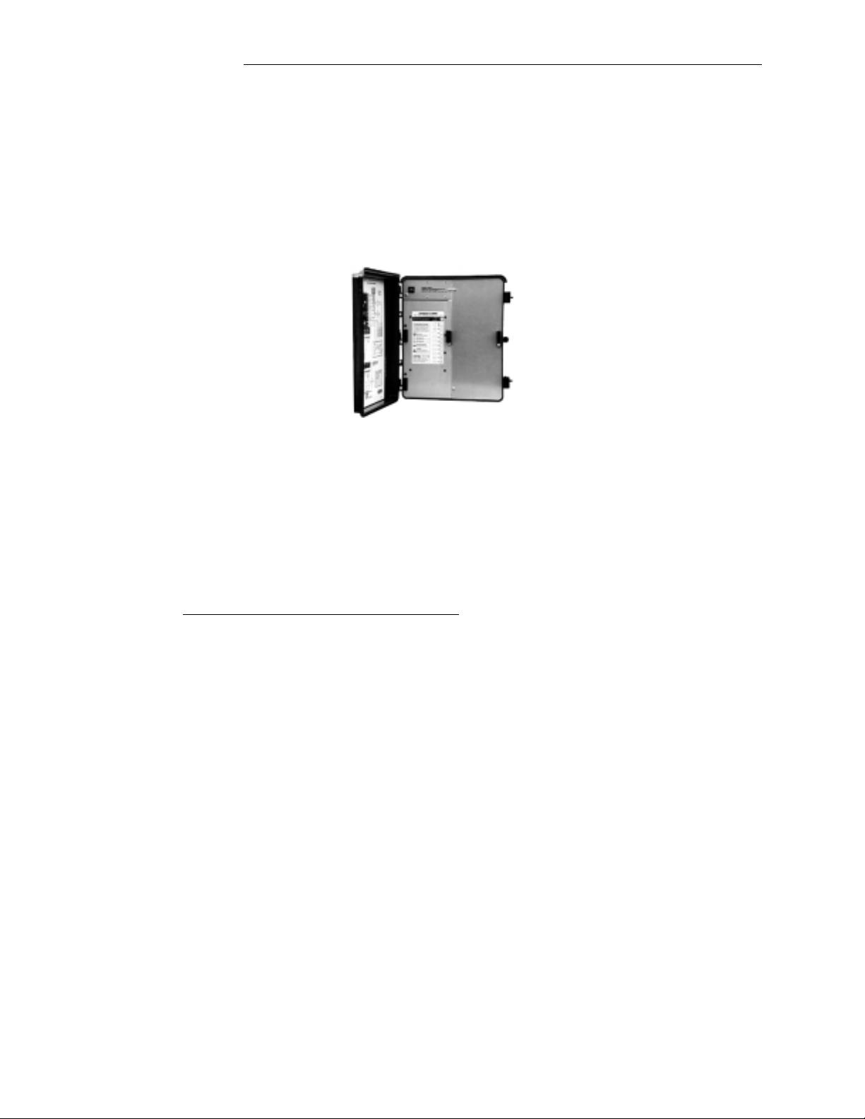
Lx3000 POWER CENTER
Lx3000 Equipment Service Keys
Located in close proximity to your pool and spa equipment, the Lx3000 Power Center provides your Pool
Serviceperson with manual control of the system without having to gain access to the Cp3000 Controller.
Caution: To prevent possible water damage, the door of the Lx3000 must be kept closed at all times.
There are no user-serviceable components located behind se rvice panel in the right-side comp artment. Do not remove
service panel. Refer service to qualified personnel only.
Equipment Service Keys and Status Lamps for all of the equipment are located in the left-side compartment.
A UTO/SERVICE KEY
Pressing this Key will toggle the Control System between “Auto” and “Service” modes:
• Auto: Keep the System in this mode during normal equipment operation. In “ Auto” mode, it will not be possible
to manually activate any of the Equipment Service Keys at the Lx3000.
30
Page 34

Compool Cp3000
Note: A blinking “Auto” Status Lamp indicates that the equipment is undergoing a 3-Hour pro gram overr ide. Se e 3HOUR FILTER OVERRIDE for details.
• Service: This mode disables the Cp3000 Controller and provides your Pool Serviceperson with complete
manual-override capability, using the various Equipment Service Keys at the Lx3000.
Note: Manual-activation of equipment from the Lx3000, will override any of the built-in equipment interlocks and
safety delay circuits.
EQUIPMENT SERVICE KEYS
Key #S:
Pressing this Key will manually toggle the Intake and Return Valve Actuators through the following options:
• Spa: Rotates both Valves to spa circulation.
• Fill: Rotates Intake Valve to pool suction and Return Valve to spa return positio ns .
• Drain: Rotates Intake Valve to spa suction and Return Valve to pool return positions.
Note: If there is no Status Lamp, both Valves will rotate to pool circulation.
Operating Instructions
Key #P:
Manually activates the filter pump.
Key #1:
Manually activates equipment connected to Aux1 circuit. Overrides Equipment Key #1 at the Cp3000 Controller.
Note: If the system incorporates an automatic pool cleaner, it is controlled by this circuit.
Keys #2 - #4:
Manually activates equipment connected to Aux2 through Aux4 circuits. Overrides Equipment Keys #2 through #4
at the Cp3000 Controller.
Keys #5 - #6:
Manually activates equipment connected to Aux5 and Aux6 circuits. Overrides Equipment Keys at Spa-Side Remote.
Heater Key:
Manually activates the heater (filter pump must also be on).
Solar Key:
Manually activates the solar valve and/or solar booster pump (if applicable).
TEMPERATURE SENSOR STATUS LAMPS
If the Control System is not receiving accurate information from a Temperature Sensor, the appropriate Status Lamp
will illuminate. Check cable and connections to appropriate Sensor. If necessary, replace Sensor (model TS-5L).
3-HOUR FILTER OVERRIDE
It is possible for the Pool Serviceperson to override t he daily equipment operating cycles, and manually activate (or
deactivate) any piece of equipment for a 3-Hour period. This is particularly u seful when adding chemicals to the pool.
31
Page 35

Compool Cp3000
Note: The Control System must be in “Auto” mode to enable this feature.
To turn the filter pump on, press Key #P (Filter Pump) 2 times quickly. The “Auto” mode Status Lamp will begin to
blink, and the Filter Pump Status Lamp will illuminate for the 3-Hour cycle.
To turn the filter pump off, press Key #P (Filter Pump) 3 times quickly. The “Auto” mode Status Lamp will begin to
blink, and the Filter Pump Status Lamp will not be illuminated during the 3-Hour cycle.
To cancel this 3-Hour cycle fro m the Lx3000 Power Center, pre ss Auto/Service Key to “Service” mode, and then b ack
to “Auto” mode.
Operating Instructions
VALVE ACTUATORS
Your control system is designed to actuate two motorized valves, which automatically rotate between pool and spa
circulation whenever the Spa is activated. A motorized valve may also be used to automatically divert the flow of
water through your solar panels (if applicable) when ever solar energy is available.
These Valve Actuators are also activated by the Spa/Fill/Drain and Solar Equipment Service Keys at the Lx3000
Power Center. Your system may also include additional motorized valves for hydraulic applications, such as a
fountain, waterfall, or pool cleaner.
SPA-SIDE REMOTE
One or more 4-button waterproof Remote Controls may be located at your spa. This will enable you to override the
Cp3000 Controller, and manually activate your spa equipment from the convenience of the spa.
32
Page 36

Compool Cp3000
Your Pool Builder will have connected this Remo te to the appropriate circuits, and labeled each push-button to suit
your particular applicatio n.
The Status Lamp (located in the center of the Spa-Side Remote) will i lluminate whenever the spa is being circulated.
Whenever the spa is being heated, the Status Lamp will blink.
SPA-SIDE HEAT BOOST OPTION
If your Spa-Side Remote incorporates a HEAT BOOST push-button, it is possible to manually activate the spa heater,
and boost the spa temperature for a five minute period after the Control System has turned the spa heater off.
This feature can only be activated if the Status Lamp at the Spa-Side Remote is on, and not blinking (i.e. the spa is
being circulated and the heater is not on).
To activate this feature, press the HEAT BOOST push-button. The Status Lamp will blink (during the 5-minute cycle)
to indicate that the spa is being heated. If you wish to turn the heater off at any time dur ing this 5-min ute cycle, press
the HEAT BOOST push-button. The Status Lamp will stop blinking to indicate that the spa is no longer being heated.
DISABLING THE SPA-SIDE REMOTE
Operating Instructions
It is possible to disable the Spa-Side Remote(s) from your Control System. This feature is convenient, if you do not
wish children to play with the Spa-Side Remote or you wish to prevent the un authorized u se of your s pa while you are
away from home.
To achieve this, press the “Remote Control at Spa” Key, which is located behind the right-side door of the Cp3000
Controller. If the status lamp is illumin a ted, the Remote Control is operational. If the status lamp is not illuminated,
the Remote Control is disabled.
33
Page 37

Compool Cp3000
Operating Instructions
SYSTEM OPTIONS
2-SPEED FILTER PUMP CONTROL
If your system incorporates a 2-Speed Filter Pump, the Cp3000 has been designed to provide you with the maximum
energy- efficient usage of this feature. See 2-SPEED FILTER PUMP CONTROL in the Installation section for details.
Although your Pool Builder may have adjusted the two speed control circuitry to your specific requirements, the
Cp3000 typically switches the pump to high speed under any of the following conditions:
1. For five minutes when the pump is first turned on. This features establishes proper flow through the system, and
packs the filter grids. After five minutes, the pump will automatically switch to low speed.
2. Whenever the poo l cleaner (if applicable) is running. This pro vides suf ficient flo w for the p ool cleaner to operate
effectively.
3. During spa circulation to increase the jet action.
4. Whenever the heater is on. Larger heaters may require high speed circulation for proper operation.
5. Whenever your solar system (if applicable) is operating. This provides high flow rate through your solar panels,
which ensures the most efficient usage of the available solar energy.
6. Whenever a dedicated Equipment Key is pressed.
SPA WATERFALL CONTROL
If your spa water level is elevated above that of the pool, it is possibl e to circulate the pool water back to the spa, thus
creating an overflow (waterfall effect) from the spa to the pool. This effect will cease during spa circulation or you
turn on your “booster pump” pool cleaner (if applicable).
This feature can be activated from Equipment Key #2 (Aux2 circuit) at the Cp3000 Controller. See SPA
WATERFALL CONTROL SWITCH for details.
FREEZE PROTECTION
It is possible to protect the plumbing and equipment from possible freeze damage by activating the filter pump and
other pumps whenever the temperature falls to 35° F ahrenheit. Your Pool builder may have already activated this
feature. See FREEZE PROTECTION SETTINGS for details.
Note: This type of freeze protection will not provide circulation of water through your solar panels. Solar freeze
protection must be accomplished by other methods. See Plumbing Requirements for details.
34
Page 38

Compool Cp3000
Maintenance
MAINTENANCE
CLEANING THE SPA
For cleaning or maintenance purposes, it is possible to use the Control System to automat ically empty your spa and
then to refill with clean water from your pool.
At the Lx3000 Power Center:
1. Press Auto/Service Key to switch the system to “Service” mode.
2. Press Key #S until “Drain” Status Lamp is illuminated.
3. Press Key #P (Filter Pump) to turn the filter pump on. The spa will begin to drain into the pool.
Caution: Do not leave equipment unattended when draining or filling the spa.
4. Before the spa has drained completely, press Key #P (Filter Pump) to turn the filter pump off. The spa will stop
draining, and cleaning can now commence.
Note: The spa should not be drained completely, or prime will be lost.
5. When cleaning is complete, press Key #S until “Fill” Status Lamp is illuminated.
6. Press Key #P (Filter Pump) to turn the filter pump on. The spa will begin to fill with clean water from the pool.
7. When the spa water level has returned to normal, press the Auto/Service Key to switch the system back to “Auto”
mode.
ADDING CHEMICALS
When adding chemicals to the water it is possible to override the daily equipment operation cycles, and activate (or
shut-off) the filter pump for a 3-Hour period. See 3-HOUR FILTER OVERRIDE for details.
WINTERIZING THE SYSTEM
During the winter season, it is possible t o disable the pool from your control system, but still be able to use your spa.
Consult a qualified service company to winterize your pool and protect the plumbing from freeze damage.
The following procedure will disable the pool equipment:
1. At the Lx3000 Power C enter, press the Auto/Service Key to switch the system to “Serv ice” mod e, an d p res s Key
#S until “Spa” Status Lamp is illuminated.
2. Flip toggle switch on back of Intake and Return Valve Actuators to OFF.
3. At the Lx3000 Power Center, press Auto/Service Key to return system to “Auto” mode.
4. At the electrical supply panel, turn off the pool cleaner circuit breaker (if applicable).
5. At the Cp3000 Controller, press the Pool Heat Source Key until “Off” Status Lamp is illuminated.
6. If your control system incorporates solar, ensure that the panels are completely drained. To inactivate the Solar
T emperature Sensor, it is necessary to adjust the “FEA TURES” Program Switch, which is located at top center of
Lx3000 circuit board. Use the corner of a small screwdriver or other blunt instrument to slide Switch #1
(SOLAR) to the OFF position.
35
Page 39

Compool Cp3000
If recirculating freeze protection has been set on your system, it may no t be necessary to winterize the pool. However,
it is recommended that the Water Temperature Sensor be calibrated accurately before the onset of the winter season.
REPLA CING THE BACK-UP BATTERY
There is a small 3-Volt lithium battery located inside the Cp3000 Controller. In the absence of power, this battery will
keep the clock running and retain the programming in memory for approximately 2 years. The display will be blank
during power failure.
While power is connected to the system, the battery will not be drained. However, it is not rechargeable. It is
recommended that the battery be replaced every 5 years.
The replacement battery is available from your pool dealer (Compool model BAT-3), or can be purchas ed at Radio
Shack or your local drug store (Type CR2032, or equivalent).
To replace the battery:
1. Do not turn the power off.
2. Open Cp3000 doors and remove the four mounting screws.
Maintenance
3. Close Cp3000 doors and pull enclosure away from wall.
4. Pry-out battery from battery clip, and replace it with a new one. Pay special attention to the polarity (+ sign faces
up).
36
Page 40

Compool Cp3000
Problem Solving
PROBLEM SOLVING
DISPLAY READS “Err"
1. At the Lx3000 Power Center, check the Water Temperature Sensor Status lamp.
2. If lamp is illuminated, check cable and connections to Sensor.
3. If necessary, replace Sensor (model TS-5L).
INCORRECT TEMPERATURE READING
Calibrate temperature sensor. See CALIBRATING TEMPERATURE SENSORS.
HEATER DOES NOT OPERATE
1. At the Cp3000 Controller, press Key #S (turn on the spa).
2. Make sure that preset temperature setting for the spa is higher than the current water temperature.
3. At the heater, make sure that the ON-OFF switch is “ON” position and temperature dial is set to highest setting.
CANNOT SELECT SOLAR HEATING
At the Lx3000 circuit board, locate “FEATURES” Program Switch, and make sure that (SOLAR) is in the “ON”
position.
SOLAR HEATING NOT ON WHEN IT SHOULD BE
1. At the Cp3000 Controller, make sure that either the pool or spa is being circulated.
2. The Cp3000 system has a 10° Fahrenheit solar differential. This means that if the pool temperature is 80°
Fahrenheit, the solar temperature must be 90° Fahrenheit or higher before the solar system is activated.
3. Check calibration of Solar Temperature Sensor. ADJ 2 will indicate the current solar temperature. If
temperature display is not correct, then adjust calibration as necessary.
EQUIPMENT DOES NOT TURN OFF AT EXPECTED TIME
1. Manual activation of equipment will o v erride an y daily operating c ycle which may be in effect. If the equipment
was turned on manually, it will run for 12 hours and automatically turn off.
2. At Cp3000 Controller, verify that the problem is not program-related. If you see PROG 1 while reviewing
programs, then that equipment has more than o ne progr am. Press same Equipmen t K e y again to vie w ad ditional
programs. Cancel programs as needed. See Programming for details
3. It is normal for the freeze protection circuitry to tu rn equip ment on when th e temperature falls to 35° Fahr enheit.
At the Lx3000 circuit board, locate 7-position “FREEZ PROT” Program Switch, and determine which circuits
have been selected for freeze protection.
EQUIPMENT TURNS OFF AFTER 12 HOURS
1. This is normal if equipment is turned on manually. A built-in 12 hour shut-off will always turn your equipment
off.
2. This function overrides programs that have both a START TIME and a RUN TIME.
37
Page 41

Compool Cp3000
EQUIPMENT TURNS ON AT AN UNEXPECTED TIME
1. At the Cp3000 Controller, verify that the problem is not program-related. If you see PROG 1 while reviewing
programs, then that equipment has more th an on e program. Press same Equipment Key again to view additional
programs. Cancel programs as needed.
2. It is normal for the freeze protection circuitry to tu rn equip ment on when th e temperature falls to 35° Fahr enheit.
At the Lx3000 circuit board, locate 7-position “FREEZ PROT” Program Switch, and determine which circuits
have been selected for freeze protection.
SPA-SIDE REMOTE NOT WORKING
At the Cp3000 Controller, locate the “Remote Con trol at Spa” Key (behind right-side d oor), and verify that status lamp
is on.
SPA-SIDE EQUIPMENT TURNS OFF AFTER 30 MINUTES
This is a normal function for Aux5 and Aux6 circuits. If you would like to disabl e thi s funct i on , adjus t the 3- pos i t ion
S1 Program Switch which is located at center right-side of the Cp3000 circuit board (see SPA-SIDE COUNTDOWN
TIMER for details).
NO DISPLAY AT Cp3000
1. At the Lx3000 Powe r Center, verify Auto/Service Status Lamp is illuminated (t his conf i rms there is power to the
system).
Problem Solving
2. Unplug communication cable from Cp3000 and Lx30 00 circuit boards. Temporarily transfer Cp3000 Controller
to equipment site, and use 4’ test cable (included with system) to interconnect Cp3000 with Lx3000.
3. If the test cable activates the Cp3000 display, repair or replace communication cable.
ABNORMAL OPERATION
Re-setting the Cp3000:
1. Remove Cp3000 control pane l from wall.
2. Disconnect 6-conductor communication cable.
3. Locate resetting pins on lower right hand corner of circuit board.
4. Unplug shorting plug from “NORMAL” position, and insert into “RESET” position.
5. Return shorting plug to “NORMAL” position.
6. Reconnect 6-conductor communication cable.
7. Re-install Cp3000 control panel.
This has reset the Cp3000 circuit board. Be sure to reset the Clock Time, Programs, and Sensor Calibration.
Re-setting the Lx3000
Turn system power off (moment arily trip system circuit breaker at sub-panel ). This will reset the Lx 3000 circuit board.
38
Page 42

Compool Cp3000
Warranty
WARRANTY
Compool Corporation warrants to the purchaser of this electronic control system, for the period of one year from the
date of original purchase for use, that any defective product proved to be caused by faulty workmanship or faulty
material, will be repaired or replaced at Compool’s o ption at no charg e, providing the product is returned to Compool
with all transportation charges prepaid.
This warranty covers the Cp3000 Controller, Lx3000 Power Center, CVA-24 Valve Actuators, and optional Remote
Controls including all component s and parts . It extends to the fir st ret ail purch aser and any s ubs equ ent owners of the
system.
This limited warranty applies only to controls which have been installed and maintained in strict accordance with
installation and operat i ng i nstructions provided by Compool Corporation , us ing i nst all at i on hard wa re s upp lied and/or
recommended in writing by Compool, and to controls which have been connected to the correct supply voltage.
This limited warranty does not apply to any controls which have been repaired or altered by anyone other than
Compool or a person authorized by it; or which have been subject to misuse, neglect or accident; or which have been
damaged by wind, rain, lightning, freezing or other cause, thing, person, or act of God; or which have been subject to
damage in transit, during installation, or by someone other than Compool Corporation; or which have been damaged
because of a defect in a component or p art which is n ot part of the C omp ool C ontrol Sys tem; or upo n wh ich the s erial
number or manufacture date has been altered, effaced or removed.
This warranty gives you specific legal rights and you may also have other rights which vary from State to State.
Compool Corporation does not authorize any person to create any other obligation o r liability in connection with
Compool controls.
Compool Corporation makes no warranty of merchantability or fitness for any use. Any implied warranty applicable
to Compool controls is limited in duration to the duration of this written warranty. Unless state law provides otherwise,
Compool Corporation shall not be liable for consequential or incidental damages resulting from breach of this written
warranty or any implied warranty, or any inconvenience, loss of time, or incidental expenses such as telephone calls.
Compool Corporation shall not be liable for any labor charges associated with the removal or reinstallation of any soclaimed defective products.
To exercise this warranty, send defective parts*, with copy of dated receipt and a brief description of the problems
encountered, postage prepaid, to:
COMPOOL CORPORATION
599 Fairchild Drive
Mountain View, California 94043
For questions, repairs, replacement parts, or information on possible Authorized Service Centers within your vicinity
call:
Compool Customer Service
1-800-458-2201
Monday - Friday
8:00 a.m. - 5:00 P.M.
Pacific Standard Time
*For your protection, you should always insure your package when shipping or mailing.
39
Page 43

Compool Cp3000
Index
INDEX
NUMERICS
2-SPEED FILTER PUMP CONTROL 15, 34
3-HOUR FILTER OVERRIDE
A
ADDING CHEMICALS 35
23
7
ADDING RELAYS
AUTO/SERVICE KEY
AUXILIARY VALVE ACTUATORS
B
BASIC PROGRAM 27
BATTERY BACK-UP
C
CALIBRATING TEMPERATURE SENSORS 20
CANCELING PROGRAM(S)
CHECKING DESIRED WATER TEMPERATURE SETTING
CLEANING THE SPA
COUNTDOWN TIMER PROGRAM
CP3000 CIRCUIT BOARD
CUSTOM CLOCK OPTIONS
CVA-24 VALVE ACTUATORS
D
DAILY EQUIPMENT OPERATING CYCLES 27
DISABLING TH E SPA-SIDE REMOTE
DISPLAY
E
EQUIPMENT KEYS 23
EQUIPMENT LOCATION
EQUIPMENT POWER
EQUIPMENT SERVICE KEYS
EQUIPMENT STATUS LAMPS
F
FAHRENHEIT/CELSIUS TEMPERATURE DISPLAY 25
FREEZE PROTECTI ON
FREEZE PROTECTION SETTINGS
G
GAS HEATER CONNECTIONS 12
31
30
22
35
7
34
15
29
28
18
18
11
33
4
31
22
16
M
MAINTENANCE 35
MOD-VLV3
MOUNTING THE CP3000 CONTROLLER
MULTIPLE PROGRAMS
O
ONCE ONLY PROGRAM 29
OPERATING INSTRUCTIONS
OVERRIDING THE SAFETY DELAY CIRCUITS
P
PLUMBING REQUIREMENTS 3
POOL AND SPA HEATING
POOL CLEANER PROTECTION
PROBLEM SOLVING
PRODUCT PACKAGE
PROGRAMMING
R
25
REPLACING THE BACK-UP BATTERY 36
REVIEWING TH E PR O G R AM(S)
S
SAFETY FEATU R E S 21
SAFETY NOTI C E
SETTING DESIRED WATER TEMPERATURE
SETTING THE CLOCK
SOLAR BOOSTER PUMP CONTROL
SOLAR ONLY
SOLAR PRIORITY
SOLAR TEMPERATURE SENSOR
SPA WATERFALL CONTROL
SPA WATERFALL CONTROL SWITCH
SPA-SIDE COUNTDOWN TIMER
SPA-SIDE HEAT BOOST OPTION
SPA-SIDE REMOTE
SPECIAL TOOLS REQUIRED
SUB-PANEL
SYSTEM OPTIONS
SYSTEM POWER
SYSTEM START-UP
T
TEMPERATURE KEYS 25
TEMPERATURE SEN SO R ST AT U S LAMPS
15
28
21
24
37
2
27
1
26
25
25
34
14,
32
5
14,
6
19
2
34
10
22
21
29
25
17
17
18
18
33
31
H
HEAT SOURCE KEY 24
HEATER PROTECTION
HIGH VOLTAGE THERMO ST AT HEA TE R
HIGH VOLTAGE WIRING
I
IMPORTANT SA FETY INSTRUCTIONS 1
INSTALLATION
L
LOW VOLTAGE CAB LES 9
LOW VOLTAGE WIRI NG
LX3000 CIRCUIT BOARD
LX3000 EQUIPMENT SERVICE KEYS
LX3000 POWER CENTER
21
5
2
9
9
5,
30
30
U
UNDERWATER LIGHTS 8
USING THE CRIMPING TOOL
16
USING YOUR SPA
V
VALVE ACTUATORS 32
W
WARRANTY 39
WATER TEMPERATURE SENSOR
WINTERIZIN G T H E SYSTEM
24
11
12
35
40
 Loading...