

Page 1
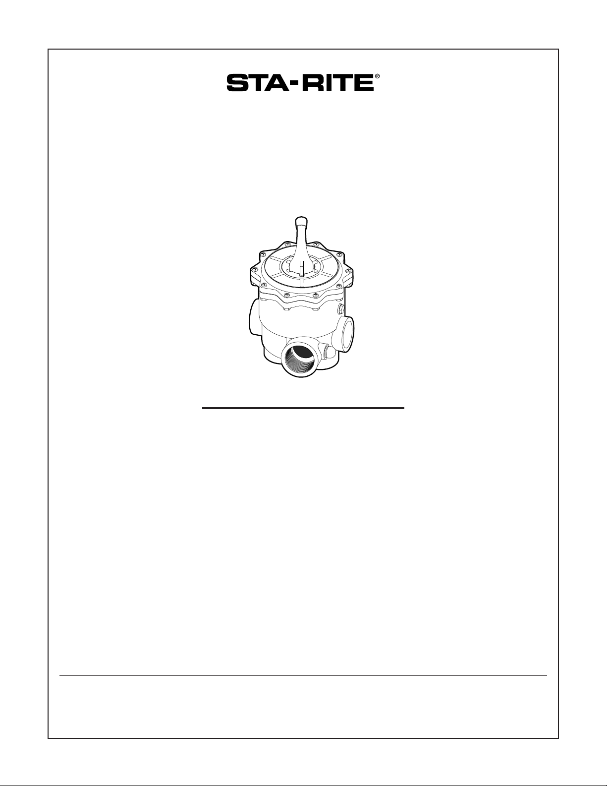
MULTI-PORT FILTER VALVE
O W N E R’ S M A N U A L
INSTALLATION, OPERATION & PARTS
MODELS
SIDE MOUNT – 1-1/2" SIDE MOUNT – 2"
18202-0150 18201-0200
18202-0150H 18201-0200H
18201-0110 18201-0300
18202-0250
Sta-Rite Pool/Spa Group
293 Wright Street, Delavan, WI 53115
International: 262-728-5551, FAX: 262-728-7550
www.starite.com
Union City, TN • Delavan, WI • Mississauga, ON • Murrieta, CA
© 2005, Sta-Rite Industries S532 (Rev. 6/24/05)
This manual should be furnished to
the end user of this valve; its use will
reduce service calls and chance of
injury and will lengthen valve life.
RECIRC.
R
W
AS
TE
IN
S
E
FILTER
3587 1099
BACKWASH
D
C
L
O
S
E
Page 2
2
MULTI-PORT FILTER
VA LV E
To avoid unneeded service calls, prevent possible injuries,
and get the most out of your filter, READ THIS MANUAL
CAREFULLY!
Table of Contents
Safety Instructions ............................................................2
General Information.........................................................3
Functions .........................................................................4
Maintenance.................................................................4-5
Repair Parts List ............................................................6,7
Performance Curves.........................................................7
Warranty..........................................................................8
READ AND FOLLOW ALL
INSTRUCTIONS!
This is the safety alert symbol. When you see this
symbol on your system or in this manual, look for
one of the following signal words and be alert to the
potential for personal injury.
warns about hazards that will cause death,
serious personal injury, or major property damage if
ignored.
warns about hazards that can cause death,
serious personal injury, or major property damage if
ignored.
warns about hazards that will or can cause
minor personal injury or property damage if ignored.
NOTICE indicates special instructions not related to hazards.
Carefully read and follow all safety instructions in this
manual and on equipment. Keep safety labels in good con-
dition; replace if missing or damaged.
Incorrectly installed or tested equipment may
fail, causing severe injury or property damage.
Read and follow instructions in owner's manual
when installing and operating equipment. Have
a trained pool professional perform all pressure tests.
1. Do not connect system to a high pressure or city water
system.
2. Use equipment only in a pool or spa installation.
3. Trapped air in system can cause explosion. BE SURE all air
is out of system before operating or testing equipment.
Before pressure testing, make the following safety checks:
• Check all clamps, bolts, lids, and system accessories
before testing.
• Release all air in system before testing.
• Tighten Sta-Rite trap lids to 30 ft. lbs. (4.1 kg-cm) torque
for testing.
• Water pressure for test must be less than 25 PSI (172 kPa).
• Water Temperature for test must be less than 100
o
F.
(38oC).
• Limit test to 24 hours. After test, visually check system to
be sure it is ready for operation. Remove trap lid and
retighten hand tight only.
NOTICE: These parameters apply to Sta-Rite equipment
only. For non-Sta-Rite equipment, consult manufacturer.
Page 3

3
GENERAL
Inspect valve upon receipt and file claim with carrier if
parts are damaged or missing.
Valve may be used with Sta-Rite DE or sand filters, except
Model HRP36.
Mating half of unions are on filters shown on Table I.
Connecting Multi-Port Valve To Filter System
For filters listed below, select correct valve clamp connector kit from the chart.
Use care before assembly not to damage union sealing surfaces or O-Ring. Install union O-Rings in groove; tighten
union collar hand tight.
FOR SLIP FITTINGS: Use correct solvent/cement when fitting
piping or adapters to slide valve. The valve body is ABS
plastic, thus any good quality ABS to PVC solvent can be
used, such as Weld-On #793 or #710. Use P70 (purple)
primer on PVC components only. Allow a minimum of four
hours drying time prior to pressure testing or operation. If
ABS adapters are glued into valve ports in lieu of PVC fittings, use Weld-On Solvent #771, #1707 or #773.
To avoid serious personal injury or property
damage, follow cement manufacturer’s instructions exactly.
NOTICE: FOR THREADED FITTINGS: Use Plasto-Joint Stik
1
,
teflon tape or RTV. Other substances may degrade plastic
and create poor joints and leaks. Do not overtighten.
1
Lake Chemical Co., Chicago, IL
TABLE I – Filters and connector kits to use with valves.
Filter Connection Chart
18201 and
Use Hose Kit No.
Port Valve Use With 18202 Series with with
Valve No. Size Outflow* Filter model Valves Replace 2" Pipe 1-1/2" Pipe
18202-0150 DES25 WC212-143P
––
for Union Connections
1-1/2"
Bottom
DES36 (Unions)
or 18202-0150H, HRS16 14964-0014 24750-0624 24750-0331
for Hose Connections HRS20 (Hoses) 2"x1-1/2" 1-1/2"x1-1/2"
18202-0250
1-1/2"
Top
PLDE36
–––
for Union Connections PLDE48
18201-0110 1-1/2"
Top
S200BP-1M
–––
S240BP-1M
DEP36, DEPB36 WC212-144PN
DEP51, DEPB51 WC212-150PN – –
18201-0200 DEP83, DEPB83 (Unions)
for Union Connections DES51, DES60
or 2" Bottom HRP20, HRP24
18201-0200H HRP30 WC212-150PA 24750-0341 –
for Hose Connections HRS24 14971-0000 2"x2"
S7M120, S8M150 (Hoses)
S7D75, S8D110
S7MD60
18201-0300 2"
Top
S7MD72 – – –
SR-300-2U
SR-360-2U – – –
* When the multiport valve handle is in filter position, flow to filter will be from this port.
Page 4

4
FUNCTIONS OF THE
MULTI-PORT VALVE
To avoid severe injury
and major property damage, stop pump before changing handle positions.
To avoid major property
damage due to flooding,
make sure pointer is accurately positioned and down all the
way before restarting pump.
Press down on handle to
release pressure before turning.
1. FILTER – Normal position during operation of system.
2. BACKWASH – Position when operating system to
purge filter of accumulated debris. This normally is
necessary when filter pressure gauge reads 10 PSI
higher than starting pressure on a clean filter. Consult
your filter operating instructions.
3. RINSE – This position is only used with sand filters
and is designed to flush stray sand from system before
returning to filter operation after backwashing.
Consult your filter operating instructions.
4. CLOSED – Valve may be set in closed position when
servicing filter tanks located below water level.
5. RECIRCULATE – This position permits pump to continue recirculating water (chemicals, heat, etc.) without flow through filter. This is advantageous when filter or its components are being repaired or replaced.
6. WASTE – This position permits draining or lowering
of pool water level. When pump is stopped with
valve in this position, quickly move handle to another
position to avoid air getting into piping.
VALVE MAINTENANCE
To avoid severe personal injury and major property
damage, stop pump and release all pressure from
system before servicing valve.
No regular maintenance is required for proper operation
of multi-port valve.
Winterizing For Freezing Climates:
Place valve handle in an intermediate position, between
regular setting positions.
Part Replacement:
To prevent flooding, make sure that system is drained or
isolation valves are closed before opening multi-port
valve.
Replacing Handle:
1. STOP PUMP and release all pressure from system.
2. Place handle in “FILTER” position.
3. Remove all bolts and nuts holding cover to valve
body.
4. Remove cover, handle, and plug as a unit from valve
body.
5. Compress plug as shown in Figures 1 and 2.
6. Remove handle pin from handle; remove handle
and replace with new one, making sure pointer
is in “FILTER” position.
7. Replace pin by tapping lightly into place with
hammer and punch.
8. Remove fixture, align cover pin (See Figure 3), and
reinstall cover and plug. Tighten all bolts securely.
Hazardous pressure.
Can cause severe
injury or major
property damage
from valve blow up.
Release all pressure
and read instructions
before working on
system.
Figure 2 – Tighten wingnuts to compress spring
Pull top of valve
down 1/2-5/8";
Tap pin out
of shaft.
3586 1099
Figure 1 – Fixture dimensions for valve spring compressor
8" (For 2" Valve)
6" (For 1-1/2" Valve)
Scrap 1x2,
1x4 or 3/4"
Ply 10" Long
1/4 x 6"
Carriage
Bolts (2)
Wing Nut
1/4" holes through (3 Places)
Flat Washer
3585 1099
Page 5

5
To prevent flooding, make sure that system is drained or
isolation valves are closed before opening multi-port valve.
Replacing Cover and Plug Assembly (as a unit):
1. STOP PUMP and release all pressure from system.
2. Remove all bolts and nuts around perimeter of cover.
3. Remove assembly by lifting straight up.
4. Align cover pin (see Figure 3) and install new cover
and plug. Press down on cover to allow bolts to
engage nuts; tighten each bolt securely.
Replacing Internal Valve Parts:
1. STOP PUMP and release all pressure from system.
2. Place handle in “FILTER” position.
3. Remove all bolts and nuts.
4. Remove cover by lifting straight up.
5. Remove handle pin and handle (See procedure on
Page 4).
6. Remove washer.
7. While disassembled, check condition of plug, rubber
gasket, spring,
O-Ring, and internal plastic washer. If any of these
parts appear worn, replace them.
8. Reassemble plug, cover, and handle by compressing
spring (See Figures 1 and 2) and reversing procedure
on Page 4.
9. Before reinstalling cover, be sure plug and handle are
in same position as when cover was removed.
10. Make sure tab on valve cover aligns with pin on top of
pump port (see Figure 3). Press down on cover or set
handle to “WINTERIZE” to allow bolts to engage nuts.
Tighten each bolt securely.
Spider Gasket Replacement:
NOTICE: Read instructions completely before starting.
Once Step 6 is started, continue through Step 10 without
interruption.
1. STOP PUMP and release all pressure from system.
2. Place the selector handle at the ‘Winterize’ position
(this lifts the plug off the seat).
3. Remove the bolts and nuts holding the cover to the
valve body. Remove the cover assembly.
4. Remove the old gasket from the valve body.
5. Make sure that the gasket groove is free of water,
grease, oils, debris and parts of the old gasket. Use
alcohol to degrease.
6. NOTICE:
Once this step is started, continue through
Step 10 without interruption.
Using Loctite®401 or 416, apply glue sparingly (a bead
about 1/16” wide) to the bottom only (not the sides) of
the spider groove in the valve body. The glue lines
must be continuous and intersect at the intersections of
the grooves.
7. Insert the new gasket into the groove with the rounded
bead up. Press the gasket firmly into all groove areas to
seat the new gasket evenly.
8. Align the tab on the cover assembly with the pin on
the valve body (See Figure 3) and insert the cover
assembly into the body, fastening it with the bolts and
nuts removed in Step 3. Tighten all bolts securely.
9. Depress the valve handle and rotate it to the closest
standard position (FILTER or RINSE), being careful not
to rub the plug on the new gasket. Release the handle,
allowing the plug to hold the gasket in place while curing.
10. Minimum cure time is 2 hours. Curing for 24 hours is
recommended for full strength.
Figure 3 – Cover alignment
BACKWASH
RECIRC.
RINSE
FILTER
WASTE
CLOSED
W
I
N
T
E
R
I
Z
E
Align
Tabs
3611 1099
Page 6

6
Side Mount Multiport Valve Assembly
REPAIR PARTS LIST
B
A
C
K
W
A
S
H
RECIRC.
R
I
N
S
E
F
I
L
T
E
R
WASTE
CLOSED
1
2
3
4
5
6
7
8
8
11
12
12A
13
14
Valve Body
Not Available
Separately
9
10
15
18201-0110
18202-0150 18201-0300
18202-0150H 18201-0200
Key 18202-0250 18201-0200H
No. Description Qty. 1-1/2" Valve 2" Valve
1 Handle 1 14971-SM10E1 14971-SM10E1
2 Label Decal 1 32155-4133 32155-4136
3 Washer 1 14971-SM10E3 14971-SM10E3
4 Valve Cover 1 14971-SM10E6 14971-SM20E6
5 Cover O-Ring 1 14971-SM10E7 14971-SM20E7
6 Washer 1 14971-SM10E8 14971-SM10E8
7 Spring 1 14971-SM10E9 14971-SM10E9
8 O-Ring 2 14971-SM10E10 14971-SM10E10
9 Plug 1 14971-SM10E11 14971-SM20E11
10 Spider Gasket 1 14971-SM10E12 14971-SM20E12
11 1/4" NPT Plug w/O-Ring 1 U178-920P U178-920P
12 Sight Glass w/O-Ring 1 14971-SM10E17 14971-SM10E17
13 Nut () 14971-SM10E14(6) 14971-SM10E14(10)
14 Bolt () 14971-SM10E4(6) 14971-SM10E4(10)
15 Handle Pin 1 14971-SM10E2 14971-SM10E2
16 O-Ring (-0150, -0200 only) 2 U9-362 U9-362
• Key Assembly (Includes 1-11,13) 1 14971-SM10E50 14971-SM20E50
Models 18202-0150, 18201-0200, 18201-0110,
18202-0250 and 18201-0300 include union
halves as shown. Table 1, Page 3 gives filter
models and correct valves to use with filters.
Models 18202-0150H and 18201-0200H
require hose connector kits (sold separately –
See Table 1, Page 4 for kit and filter numbers).
• Not illustrated.
16
Page 7

7
Sight Glass Adaptor – 11⁄2" NPT & Hose ..............................Order #14962-0012
Sight Glass Adaptor – 11⁄2" NPT...........................................Order #14962-0013
• Male Adaptor – 11⁄2" NPT to 11⁄2" ID Hose............................Order #U78-767P
• Not illustrated.
Performance Curves – Multi-Port Valves
11⁄2" and 2" Side Mount Valves with Piping
Sight Glass, Sight Glass Adaptors
0
40
60 80 100 120 140 160
2
4
6
8
10
12
14
16
Capacity (GPM)
P.S.I. Loss
2" Valve
1-1/2"
Valve
Backwash Position
Filter Position
3588 1099
2840 0597
2841 0597
Page 8

CREATE A RECORD OF YOUR WARRANTY AT STA-RITE:
• Complete a warranty registration at www.staritepool.com by clicking on “Register Products” and selecting Sta-Rite Pool
OR
• Complete bottom portion completely and mail within 10 days of installation to Sta-Rite, Attn.: Pool Warranty Dept., 293 Wright St., Delavan , WI 53115
Warranty Registration Card
Name
Address
City State Zip
Installation (or Purchase) Date
Product Purchased
Model Number
■■ New installation ■■ Replacement
Years pool has been in service ■■ less than 1 ■■ 1-3 ■■ 3-5 ■■ 5-10
This product was purchased from:
Company name
Address
City State Zip
STA-RITE LIMITED WARRANTY
For technical information about this product, contact the installer or call Sta-Rite at 262-728-9181.
Visit www.staritepool.com
• for more information about Sta-Rite products listed above
• to locate a Sta-Rite dealer near you
Product Specific Warranties (from date of installation)
Product Limited
Family Warranty Exceptions
Filters 1 Year System 3 Tank Bodies - 10 Yrs
Filter Valves 1 Year
Pumps 1 Year
Heaters 2 Years *Commercial Application - 1 Yr
Controls 1 Year
Above Ground Systems 1 Year
Lights and Niches 1 Year Lamps and Bulbs - 90 Days
White Goods 1 Year
Maintenance Equipment 90 Days
Drainer/Utility Pumps 90 Days
Replacement Parts 90 Days
Cleaners: Lil Shark 1 Year
Cleaners: Calypso 1 Year
Cleaners: Pool Shark 2 Years Footpad and Seal Flaps - 1 Yr
Cleaners: Great White 2 Years
* Commercial and multi-family application.
Retain this warranty certificate in a
safe and convenient location for your records.
Pumps, filters, skimmers, underwater lights (excluding bulbs),
accessories and fittings manufactured by Sta-Rite are warranted
to be free of defects in material and/or workmanship for one (1)
year from the original date of installation.
The foregoing warranties relate to the original consumer purchaser (“Purchaser”) only. Sta-Rite Industries shall have the option to
repair or replace the defective product, at its sole discretion.
Purchasers must pay all labor and shipping charges necessary to
replace the product covered by this warranty. Requests for warranty service must be made through the installing dealer. This
warranty shall not apply to any product that has been subject to
negligence, misapplication, improper installation or maintenance,
or other circumstances which are not in Sta-Rite’s direct control.
Failure to have product installed by a professional in compliance
with local codes will void any and all manufacturers warranty.
This warranty sets forth Sta-Rite’s obligation and Purchaser’s
exclusive remedy for defective products.
STA-RITE SHALL NOT BE LIABLE FOR ANY CONSEQUENTIAL,
INCIDENTAL OR CONTINGENT DAMAGES WHATSOEVER.
THE FOREGOING WARRANTIES ARE EXCLUSIVE AND IN
LIEU OF ALL OTHER EXPRESS WARRANTIES. IMPLIED
WARRANTIES, INCLUDING BUT NOT LIMITED TO THE
IMPLIED WARRANTIES OF MERCHANTABILITY AND FITNESS
FOR A PARTICULAR PURPOSE, SHALL NOT EXTEND
BEYOND THE DURATION OF THE APPLICABLE EXPRESS
WARRANTIES PROVIDED HEREIN.
Some states do not allow the exclusion or limitation of incidental
or consequential damages or limitations on how long an implied
warranty lasts, so the above limitations or exclusion may not
apply to you. This warranty gives you specific legal rights and you
may also have other rights which vary from state to state.
Supersedes all previous publications.
S4877PS (Rev. 7/21/04)
 Loading...