

Page 1

Dot Matrix Printer
SP2000 Series
Programmer’s Manual
Page 2

TABLE OF CONTENTS
1. Control Codes (Star Mode) ......................................................................... 1
1-1. Control Codes List ..............................................................................1
1-1-1. Character Selection ..................................................................1
1-1-2. Print Position Control............................................................... 3
1-1-3. Dot Graphics Control ............................................................... 4
1-1-4. Download Graphics Printing.................................................... 4
1-1-5. Peripheral Device Control........................................................ 4
1-1-6. Auto Cutter Control (SP2500 type printers only) .................... 5
1-1-7. Commands to Set the Page Format ..........................................5
1-1-8. Other Commands...................................................................... 6
1-2. Control Code Details...........................................................................7
1-2-1. Character Selection .................................................................. 7
1-2-2. Print Position Control ............................................................. 17
1-2-3. Dot Graphics Control .............................................................25
1-2-4. Download Graphics Printing .................................................. 28
1-2-5. Peripheral Device Control ...................................................... 31
1-2-6. Auto Cutter Control (SP2500 type printers only) .................. 33
1-2-7. Command to Set the Page Format .......................................... 35
1-2-8. Other Commands.................................................................... 36
2. ESC/POS Mode Commands....................................................................... 48
2-1. Control Codes List ............................................................................ 48
3. Auto Status Specifications......................................................................... 51
3-1. Auto Status ........................................................................................ 51
Appendix : Character Code Tables................................................................57
Please access the following URL
http://www.star-micronics.co.jp/service/sp_sup_e.htm
for the lastest revision of the manual.
Page 3
1. Control Codes (Star Mode)
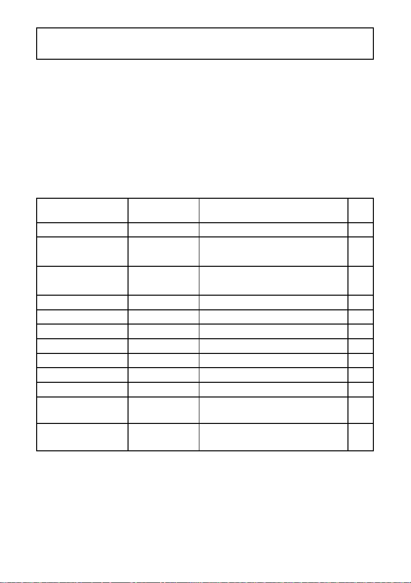
1-1. Control Codes List
The following tables show the Star Mode commands that are supported by
this printer.
1-1-1. Character Selection
Control Hexadecimal Function Page
Codes Codes
<ESC> "R"
<ESC> "/" "1" 1B 2F 31
<ESC> "/" <1> 1B 2F 01
<ESC> "/" "0" 1B 2F 30
<ESC> "/" <0> 1B 2F 00
<ESC> <GS> "t"
<ESC> "6" 1B 36 Selects character set #2 10
<ESC> "7" 1B 37 Selects character set #1 10
<ESC> "M" 1B 4D Selects the 7 X 9 (half dot) font (Default) 10
<ESC> "P" 1B 50 Selects the 5 X 9 (2 pulses per dot) font 11
<ESC> ":" 1B 3A Selects the 5 X 9 (3 pulses per dot) font 11
<ESC> <SP>
<SO> 0E Sets the printing magnified double in
<DC4> 14 Resets the printing magnified in
n
n
n
1B 52
n
1B 1D 74
1B 20
n
Selects the international character set 7
Selects slash zero
Selects normal zero 7
n
Selects the character code table 8
Sets character spacing 11
character width
character width (Default)
12
12
7
1
Page 4

Control Hexadecimal Function Page
Codes Codes
<ESC> "W" "1" 1B 57 31 Selects double magnification in character
<ESC> "W" <1> 1B 57 01 width
<ESC> "W" "0" 1B 57 30
<ESC> "W" <0> 1B 57 00
<ESC> "h" "1" 1B 68 31 Selects double magnification in character
<ESC> "h" <1> 1B 68 01 height
<ESC> "h" "0" 1B 68 30
<ESC> "h" <0> 1B 68 00
<ESC> "-" "1" 1B 2D 31
<ESC> "-" <1> 1B 2D 01
<ESC> "-" "0" 1B 2D 30
<ESC> "-" <0> 1B 2D 00
<ESC> "_" "1" 1B 5F 31
<ESC> "_" <1> 1B 5F 01
<ESC> "_" "0" 1B 5F 30
<ESC> "_" <0> 1B 5F 00
<ESC> "4" 1B 34 Selects red color printing (SP2360/2560)
<ESC> "5" 1B 35 Cancels red color printing (SP2360/2560)
<SI> 0F Inverted printing 14
<DC2> 12 Cancels inverted printing (Default) 15
<ESC> <RS> "i" "0" 1B 1E 96 30 Cancels rotated print mode for text
<ESC> <RS> "i" <0> 1B 1E 96 00 (Default)
<ESC> <RS> "i" "1" 1B 1E 96 31 Specifies rotated print mode for text with
<ESC> <RS> "i" <1> 1B 1E 96 01 a 270° rotation.
<ESC> <RS> "i" "2" 1B 1E 96 32 Specifies rotated print mode for text with
<ESC> <RS> "i" <2> 1B 1E 96 02 a 90° rotation.
<ESC> "E" 1B 45 Selects emphasized printing 15
<ESC> "F" 1B 46 Cancels emphasized printing (Default) 15
<ESC> "U"
n
1B 55
n
Resets magnification in character width 12
Resets magnification in character height 12
Selects underlining 13
Cancels underlining (Default) 13
Selects upperlining 13
Cancels upperlining (Default) 14
Selects highlight printing (SP2320/2520)
Cancels highlight printing (SP2320/2520)
Selects print direction 16
12
12
14
14
15
15
15
2
Page 5
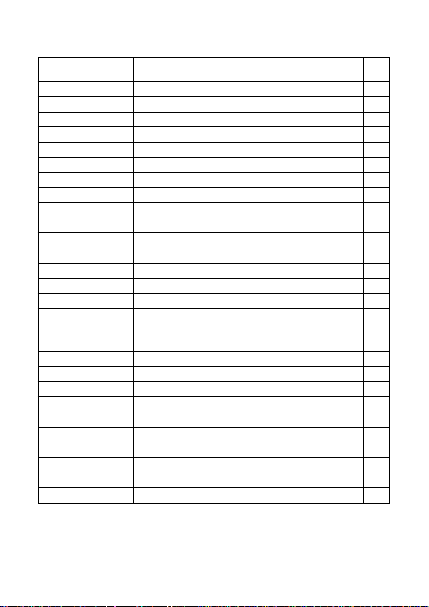
1-1-2. Print Position Control
Control Hexadecimal Function Page
Codes Codes
<LF> 0A Line feed 17
<VT> 0B Vertical tab 17
<FF> 0C Form feed 17
<CR> 0D Carriage Return 18
<ESC> "a"
<HT> 09 Horizontal tab 18
<ESC> "A"
<ESC> "2" 1B 32 Sets n/72-inch line spacing 19
<ESC> "z" "0" 1B 7A 30
<ESC> "z" <0> 1B 7A 00
<ESC> "z" "1" 1B 7A 31
<ESC> "z" <1> 1B 7A 01
<ESC> "0" 1B 30 Sets line spacing to 1/8-inch 19
<ESC> "1" 1B 31 Sets line spacing to 7/72-inch 20
<ESC> "J"
<ESC> "3"
<ESC> "y" 1B 79
<ESC> "D"
<ESC> "l"
<ESC> "Q"
<ESC> <GS> "a" "0" 1B 1D 61 30
<ESC> <GS> "a" <0> 1B 1D 61 00
<ESC> <GS> "a" "1" 1B 1D 61 31
<ESC> <GS> "a" <1> 1B 1D 61 01
<ESC> <GS> "a" "2" 1B 1D 61 32
<ESC> <GS> "a" <2> 1B 1D 61 02
<ESC> "B"
n
n
n
n
n1 n2
... <0> 1B 44
n
n
n1 n2
1B 61
1B 41
1B 4A
1B 33
1B 6C
1B 51
... <0> 1B 42
n
n
n
n
n
n1 n2
n
n
n1 n2
... 00 Set vertical tab stops 24
Feeds paper n lines 18
Defines n/72-inch line spacing 19
Sets line spacing to 1/12-inch 19
Sets line spacing to 1/6-inch (Default) 19
One time n/72-inch feed 20
Sets line spacing to n/216-inch
approximately
Sets line spacing to n/144-inch 20
... 00 Sets horizontal tab stops 21
Sets left margin 21
Sets right margin 22
Left justification (Default) 23
Centering 23
Right justification 23
20
3
Page 6
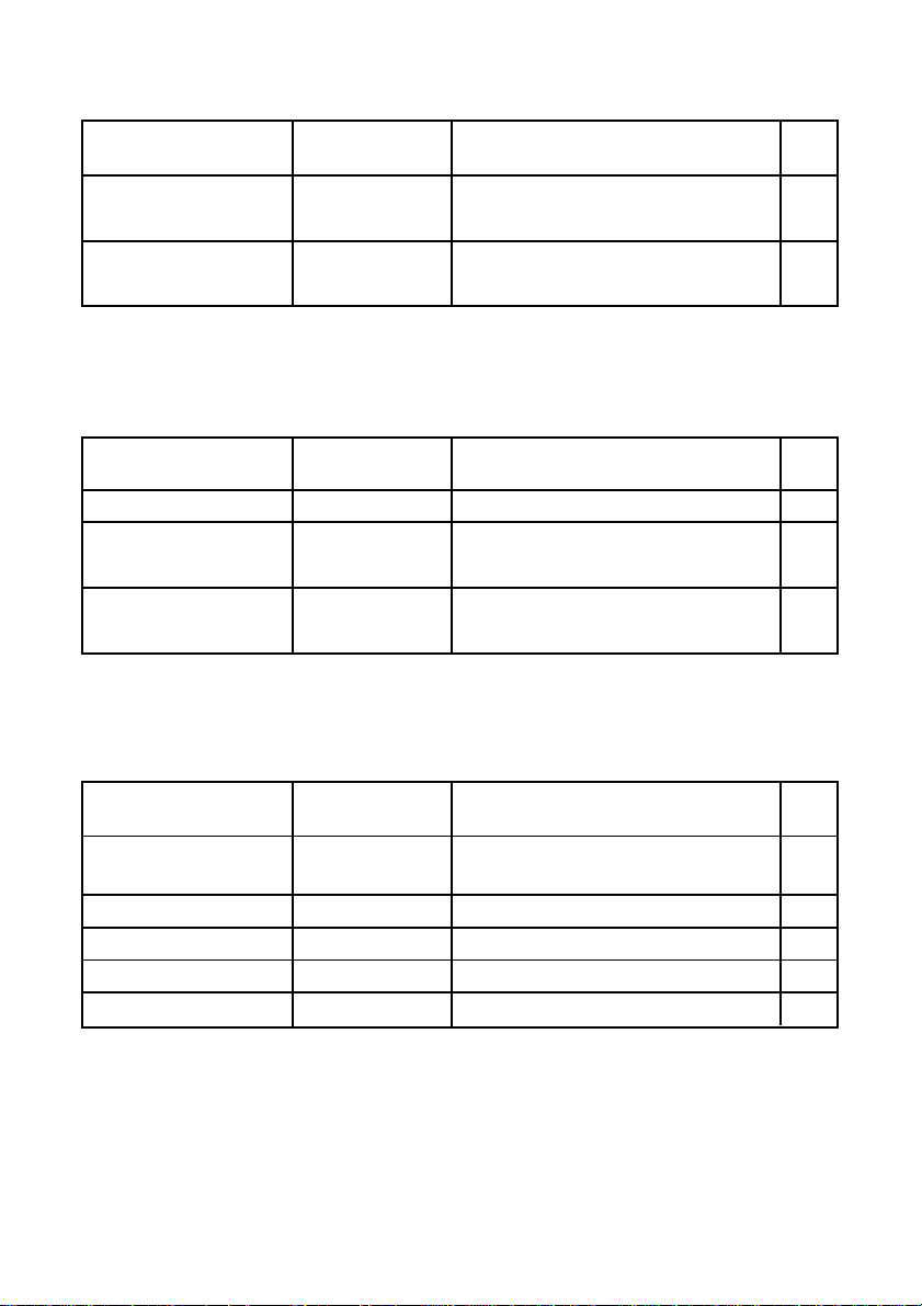
1-1-3. Dot Graphics Control
Control Hexadecimal Function Page
Codes Codes
<ESC> "K" n <0> 1B 4B n 00
m1 m2 ... ...
<ESC> "L" n1 n2 1B 4C n1 n2
m1 m2
... ...
m1 m2
m1 m2
8 dot normal density graphics 25
8 dot high density graphics 26
1-1-4. Download Graphics Printing
Control Hexadecimal Function Page
Codes Codes
<ESC> "&" <0> n1 n2 .. 1B 26 00 n1 n2 .. Defines download characters 28
<ESC> "%" "1" 1B 25 31
<ESC> "%" <1> 1B 25 01
<ESC> "%" "0" 1B 25 30 Disables download character set
<ESC> "%" <0> 1B 25 00 (Default)
Enables download character set 29
29
1-1-5. Peripheral Device Control
Control Hexadecimal Function Page
Codes Codes
<ESC> <BEL> n1 n2 1B 07 n1 n2 Defines drive pulse width for peripheral
device #1
<BEL> 07 Controls peripheral device #1 31
<FS> 1C Controls peripheral device #1 immediately 32
<EM> 19 Controls peripheral device #2 immediately 32
<SUB> 1A Controls peripheral device #2 immediately 32
4
31
Page 7
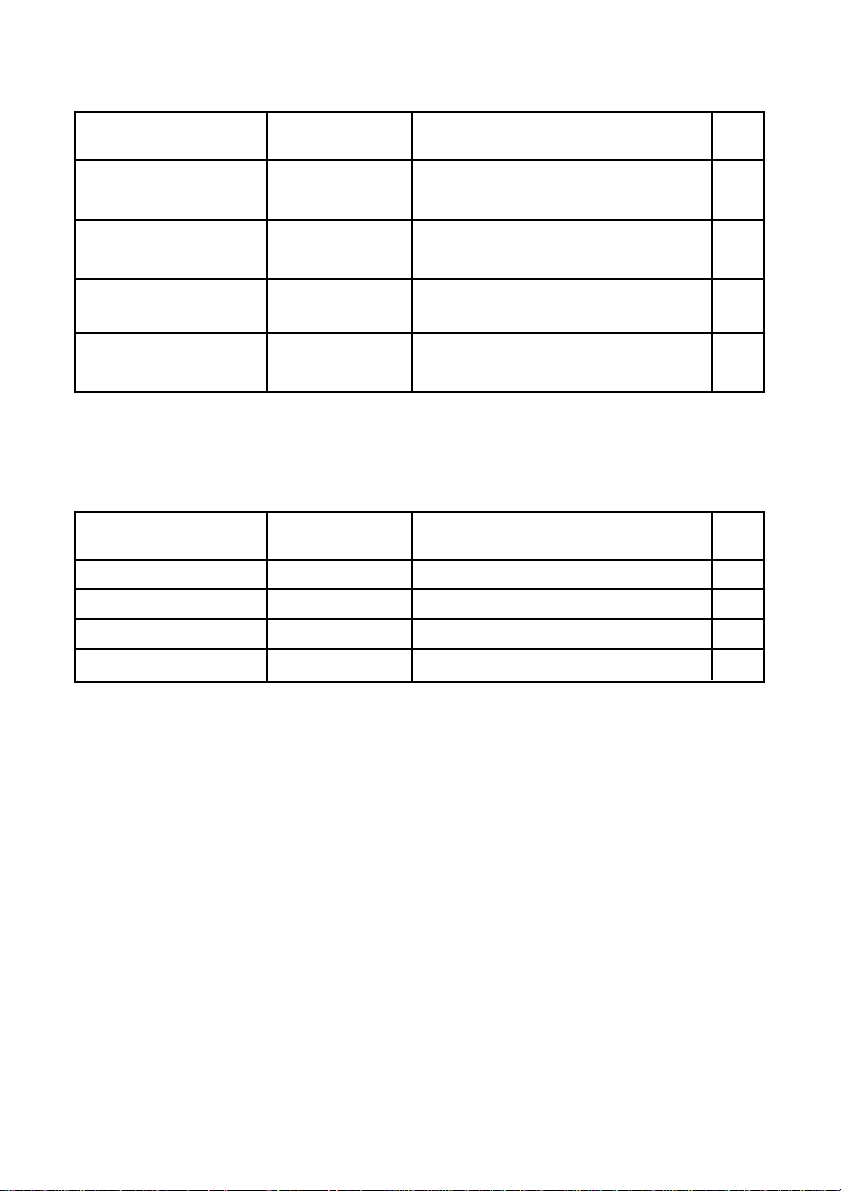
1-1-6. Auto Cutter Control (SP2500 type printers only)
Control Hexadecimal Function Page
Codes Codes
<ESC> "d" "0" 1B 64 30
<ESC> "d" <0> 1B 64 00
<ESC> "d" "1" 1B 64 31
<ESC> "d" <1> 1B 64 01
<ESC> "d" "2" 1B 64 32 Full-cut command to the auto cutter
<ESC> "d" <2> 1B 64 02 after paper feed
<ESC> "d" "3" 1B 64 33 Partial-cut command to the auto cutter
<ESC> "d" <3> 1B 64 03 after paper feed
Full-cut command to the auto cutter 33
Partial-cut command to the auto cutter 33
33
34
1-1-7. Commands to Set the Page Format
Control Hexadecimal Function Page
Codes Codes
<ESC> "C"
<ESC> "C" <0>
<ESC> "N"
<ESC> "O" 1B 4F Cancel bottom margin (Default) 35
n
n
n
1B 43
n
1B 43 00
1B 4E
n
Set page length in lines 35
n
Set page length in inches 35
Set bottom margi
n
35
5
Page 8
1-1-8. Other Commands
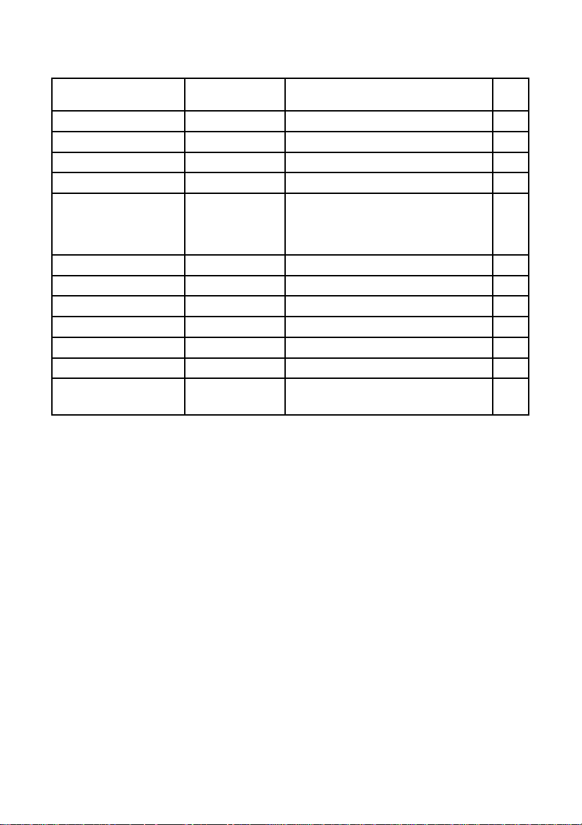
Control Hexadecimal Function Page
Codes Codes
<CAN> 18 Cancels printer buffer & Initialize printer 36
<DC3> 13 Deselects printer 36
<DC1> 11 Sets select mode (Default) 36
<RS> 1E Beeps the buzzer 36
<ESC> "#N, n1 n2 n3 n4" 1B 23 N 2C n1 n2
<LF> <NUL>
<ESC> "@" 1B 40 Initialize printer 43
<EOT> 04 Transmits EOT status 44
<ENQ> 05 Transmits ENQ status 45
<ETB> 17 Confirms finish of printing 46
<ESC> <ACK> <SOH> IB 06 01 Transmits automatic status 46
<ESC> <RS> "a"
<ESC> "?" <LF> <NUL> 1B 3F 0A 00 Resets printer hardware and produce
n
n3 n
4 Sets memory switch 37
0A 00
IB IE 61
n
Enables/disables automatic status 47
a test print
47
6
Page 9
1-2. Control Code Details
The following section explains the details of the printer control codes.
1-2-1. Character Selection
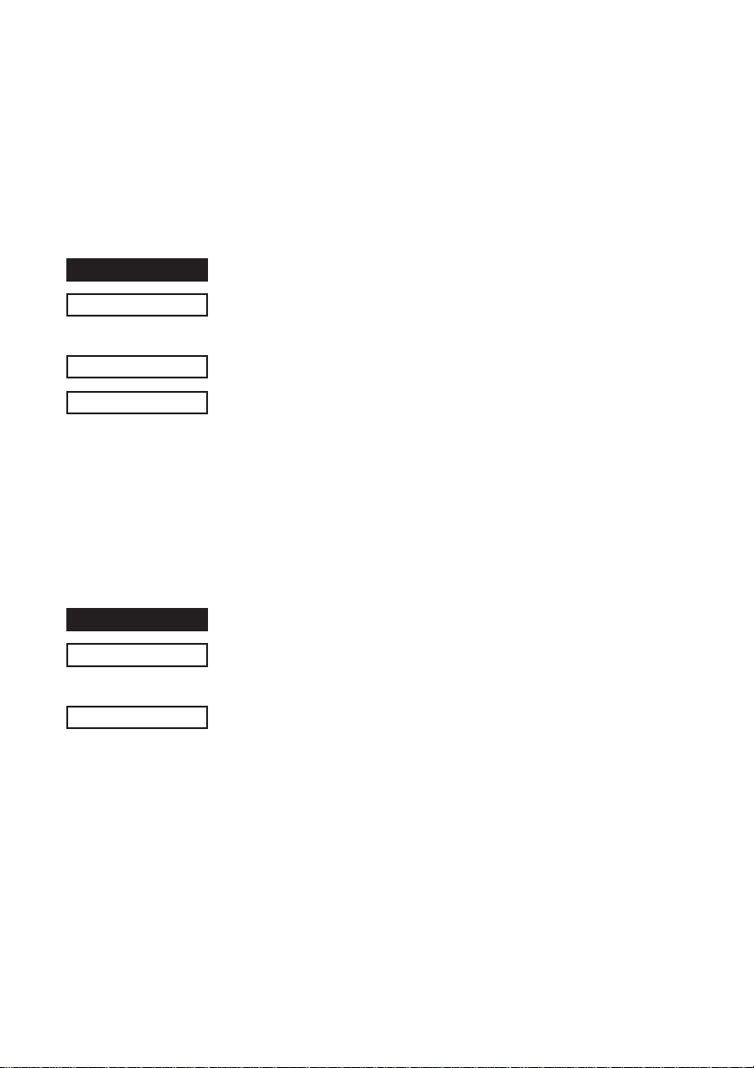
FUNCTION
CODE
DEFINITION RANGE
OUTLINE
FUNCTION
CODE
OUTLINE
Selects the international character set
<ESC> "R"
(1B)H (52)H
(00)H n (0E)H or n = (40)H
Select the international character set corresponding to the value
set for n.
n
= (00)H: U.S.A. (06)H: Italy (OC)H: Latin America
(01)H: France (07)H: Spain-1 (0D)H: Korea
(02)H: Germany (08)H: Japan (0E)H: Ireland
(03)H: England (09)H: Norway (40)H: Legal
(04)H: Denmark-1 (0A)H: Denmark-2
(05)H: Sweden (0B)H: Spain-2
Default abides by memory switches 1-0 to 1-3.
Selects zero style
<ESC> "/"
1B 2F
Selects zero style
Causes subsequent zero characters to be printed with a slash
when n is 1 and without a slash when n is 0. The value of n can
be set to 0 (00H) or "0" (30)H or 1(0H) or "1" (31H).
The default may differ depending on the memory switch setting.
n
n
<
<
=
=
n
n
7
Page 10

FUNCTION
Selects the character code table
CODE
OUTLINE
<ESC> <GS> "t"
1B 1D 74
Selects the character code table
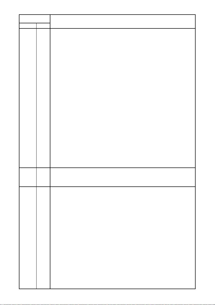
This function selects a character code table (as shown below).
The default settings follow the settings of the memory switches 38 to 3-5.
n
n
8
Page 11
Value of
Hex. Dec.
00 0 Normal (Default)
01 1 Code Page 437 (USA, Std. Europe)/IBM Character Set #2
02 2 Katakana
03 3 IBM Character Set #1
04 4 Codepage 858 (Multilingual)
05 5 Codepage 852 (Latin-2)
06 6 Codepage 860 (Portuguese)
07 7 Codepage 861 (Icelandic)
08 8 Codepage 863 (Canadian French)
09 9 Codepage 865 (Nordic)
0A 10 Codepage 866 (Cyrillic Russian)
0B 11 Codepage 855 (Cyrillic Bulgarian)
0C 12 Codepage 857 (Turkish)
0D 13 Codepage 862 (Hebrew)
0E 14 Codepage 864 (Arabic)
0F 15 Codepage 737 (Greek)
10 16 Codepage 851 (Greek)
11 17 Codepage 869 (Greek)
12 18 Codepage 928 (Greek)
13 19 Codepage 772 (Lithuanian)
14 20 Codepage 774 (Lithuanian)
15 21 Codepage 874 (Thai)
20 32 Codepage 1252 (Windows Latin-1)
21 33 Codepage 1250 (Windows Latin-2)
22 34 Codepage 1251 (Windows Cyrillic)
40 64 Codepage 3840 (IBM-Russian)
41 65 Codepage 3841 (Gost)
42 66 Codepage 3843 (Polish)
43 67 Codepage 3844 (CS2)
44 68 Codepage 3845 (Hungarian)
45 69 Codepage 3846 (Turkish)
46 70 Codepage 3847 (Brazil-ABNT)
47 71 Codepage 3848 (Brazil-ABICOMP)
48 72 Codepage 1001 (Arabic)
49 73 Codepage 2001 (Lithuanian-KBL)
4A 74 Codepage 3001 (Estonian-1)
4B 75 Codepage 3002 (Estonian-2)
4C 76 Codepage 3011 (Latvian-1)
4D 77 Codepage 3012 (Latvian-2)
4E 78 Codepage 3021 (Bulgarian)
4F 79 Codepage 3041 (Maltese)
n
Character Table
9
Page 12
FUNCTION
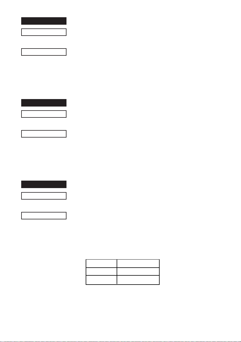
Selects IBM character set #2
CODE
OUTLINE
FUNCTION
CODE
OUTLINE
FUNCTION
CODE
<ESC> "6"
(1B)H (36)H
Selects IBM character set #2.
Switches from IBM character set #1 to character set #2.
Subsequent 80H to 9FH codes are handled as character data.
This command is invalid when the character code table settings
are other than #1.
Selects IBM character set #1
<ESC> "7"
(1B)H (37)H
Selects IBM character set #1.
Switches from IBM character set #2 to character set #1.
Subsequent 80H to 9FH codes are handled as character data.
This command is invalid when the character code table settings
are other than #2.
Selects 7 X 9 (half dot) font (Default)
<ESC> "M"
(1B)H (4D)H
OUTLINE
Selects 7 X 9 (half dot) font.
When the power of the printer is turned on, 7 X 9 (half dot)
printing is automatically selected.
The number of digits per line is set by the DIP switches in the
following way.
DSW 1 - 5 Digits Per Line
ON 42
OFF 40
(When right space of character is 0.)
10
Page 13
FUNCTION
Selects 5 X 9 (2 pulses per dot) font
CODE
OUTLINE
FUNCTION
CODE
OUTLINE
<ESC> "P"
(1B)H (50)H
Selects 5 X 9 (2 pulses = 1 dot) font.
The number of digits per line is set by the DIP switches in the
following way.
DSW 1 - 5 Digits Per Line
ON 35
OFF 33
(When right space of character is 0.)
Selects 5 X 9 (3 pulses per dot) font
<ESC> ":"
(1B)H (3A)H
Selects 5 X 9 (3 pulses = 1 dot) font.
The number of digits per line is set by the DIP switches in the
following way.
DSW 1 - 5 Digits Per Line
ON 23
OFF 22
FUNCTION
CODE
OUTLINE
Selects character spacing
<ESC> <SP>
1B 20
Sets the size of space to right of character. The value of n can be
set from 0 through 15, or from"0" through 9" and "A" through "F."
Spaces are doubled when printing using Printing magnified
double in character width.
The default value of n is 0.
n
n
11
Page 14
FUNCTION
Sets the printing magnified double in character width
CODE
OUTLINE
FUNCTION
CODE
OUTLINE
FUNCTION
CODE
OUTLINE
<SO>
(0E)H
Data following this code is printed in double-width characters.
Same as <ESC> "W" "1" or <ESC> "W" <1>.
Resets the printing magnified in character width (Default)
<DC4>
(14)H
Cancels expanded character mode set by <SO> or <ESC> "W"
"1" or <ESC> "W" <1> code. Data following this code is printed
out in normal size characters.
Same as <ESC> "W" "0" or <ESC> "W" <0>.
Selects double magnification in character width
<ESC> "W" "1" or <ESC> "W" <1>
(1B)H (57)H (31)H or (1B)H (57)H (01)H
Data following this code is printed in double-width characters.
Same as <SO>.
FUNCTION
CODE
OUTLINE
FUNCTION
CODE
Resets magnification in character width
<ESC> "W" "0" or <ESC> "W" <0>
(1B)H (57)H (30)H or (1B)H (57)H (00)H
Cancels expanded character mode set by <ESC> "W" "1" or
<ESC> "W" <1> or <SO> code. Data following this code is
printed out in normal size characters.
Same as <DC4>.
Selects double magnification in character height
<ESC> "h"
1B 68
n
n
12
Page 15
OUTLINE
Sets the magnification rate in character height
Prints the subsequent data with a character height magnified by a
rate specified by the value of n.
n
= 0 and "0"' Reset magnification
n
= 1 and "1": Double magnification
Note:
• You can print in quadruple magnification by combining
horizontal and vertical double magnification commands.
• You cannot combine with the inverted printed command.
• Line feeds of lines including vertical expansion characters are
doubled.
• When font configuration is 6 X 12 dots of IBM block graphics
characters, only the line amount is doubled.
• The bottom of the characters are aligned when one line
contains both vertical expanded characters and regular
character sizes.
FUNCTION
CODE
OUTLINE
FUNCTION
CODE
OUTLINE
FUNCTION
CODE
OUTLINE
Selects underlining
<ESC> "-" "1" or <ESC> "-" <1>
(1B)H (2D)H (31)H or (1B)H (2D)H (01)H
Data following this code is printed out underlined. (However, the
spaces generated by horizontal tab are not underlined.)
Cancels underlining (Default)
<ESC> "-" "0" or <ESC> "-" <0>
(1B)H (2D)H (30)H or (1B)H (2D)H (00)H
Cancels underlined mode.
Selects upperlining
<ESC> "_" "1" or <ESC> "_" <1>
(1B)H (5F)H (31)H or (1B)H (5F)H (01)H
Data following this code is printed out with an upperline.
(However the spaces generated by horizontal tab are not
upperlined.)
13
Page 16
FUNCTION
Cancels upperlining (Default)
CODE
OUTLINE
FUNCTION
CODE
OUTLINE
FUNCTION
<ESC> "_" "0" or <ESC> "_" <0>
(1B)H (5F)H (30)H or (1B)H (5F)H (00)H
Cancels upperline mode.
Selects red color printing (SP2360/2560)
Selects highlight printing (SP2320/2520)
<ESC> "4"
(1B)H (34)H
(SP2360/2560) Specifies red printing
Prints subsequent characters in red. You can pr int both read and
black characters on the same line.
Unidirectional when switching red and black.
(SP2320/2520) Specifies black and white inverted printing
Inverts black and white and prints subsequent characters
including the character pitch. Printing is unidirectional. Do not
use when ANK font setting is 5 X 9 (3P = 1). (Printing quality is
not guaranteed with 5 X 9 (3P = 1)).
Cancels red color printing (SP2360/2560)
Cancel highlighted print mode (SP2320/2520)
CODE
OUTLINE
FUNCTION
CODE
OUTLINE
<ESC> "5"
(1B)H (35)H
(SP2360/2560) Cancels red color printing and prints subsequent
characters in black.
(SP2320/2520) Cancels highlighted printing. (Default)
Inverted printing
<SI>
(0F)H
Data following this code is printed out in inverted characters. This
code is valid only when input at the beginning of a line, so, normal
and inverted characters cannot be mixed in on the same line.
14
Page 17
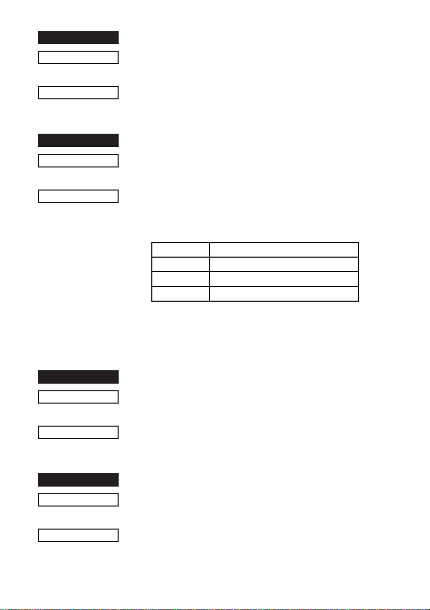
FUNCTION
Cancels inverted printing (Default)
CODE
OUTLINE
FUNCTION
CODE
OUTLINE
<DC2>
(12)H
Cancels the inverted character mode. This code is valid only
when input at the beginning of a line.
Specifies rotated print mode for text with a rotation
<ESC> <RS> "i"
1B 1E 96
This rotates and prints subsequent data 90° or 270° in the
clockwise direction or cancels it and prints. The n value
determines whether a rotational direction or a cancellation of the
rotation is specified.
n
Value Rotation Specification
00H or "0" Cancel rotation (0° rotation, default)
01H or "1" 270° rotation
02H or "2" 90° rotation
Underline or overline cannot be applied for rotated text. The
relationship of the vertical ratio and horizontal ratio for rotated
text is the reverse of when the rotation is cancelled.
n
n
FUNCTION
CODE
OUTLINE
FUNCTION
CODE
OUTLINE
Selects emphasized printing
<ESC> "E"
(1B)H (45)H
Data following this code is printed in the emphasized print mode.
In this mode, printing is uni-directional.
Cancels emphasized printing (Dafault)
<ESC> "F"
(1B)H (46)H
Cancels emphasized print mode.
15
Page 18

FUNCTION
Selects uni-directional print mode
CODE
OUTLINE
FUNCTION
CODE
OUTLINE
<ESC> "U" "1" or <ESC> "U" <1>
(1B)H (55)H (31)H or (1B)H (55)H (01)H
Prints only when the print head moves from left to right.
Selects bi-directional print mode
<ESC> "U" "0" or <ESC> "U" <0>
(1B)H (55)H (30)H or (1B)H (55)H (00)H
Returns to the standard bi-directional print mode. (This mode is
set automatically when the printer power is turned on.)
16
Page 19
1-2-2. Ptint Position Control
FUNCTION
CODE
OUTLINE
FUNCTION
CODE
OUTLINE
FUNCTION
CODE
Line feed
<LF>
(0A)H
Data in the line buffer is printed out and one line is fed. If data
does not exist before this code is received, the printer only feeds
one line.
Vertical tab
<VT>
(0B)H
Feeds the paper to the next vertical tab set position.
When a vertical tab is not set, line feed is not performed. If the
current line is at or below the last vertical tab set position, the
paper feeds to the top of the next page.
Form feed
<FF>
(0C)H
OUTLINE
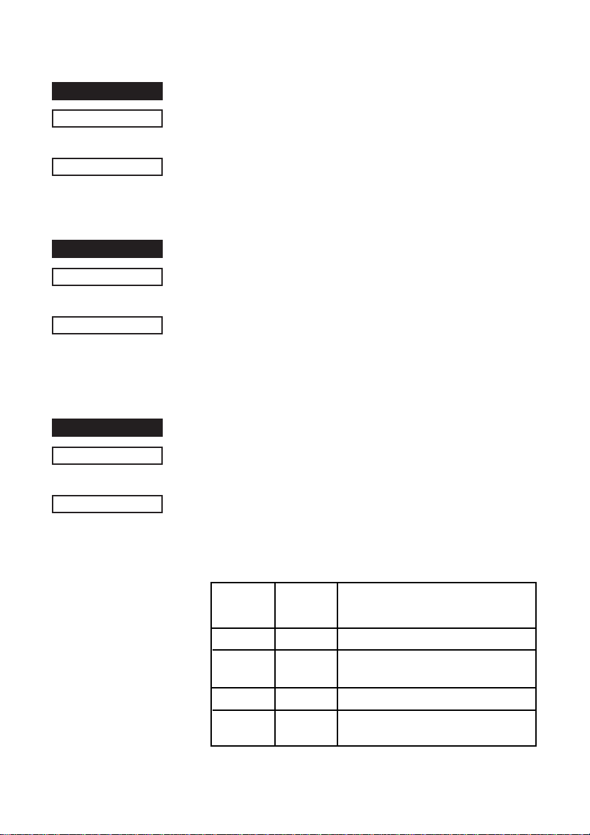
Inputting this code executes a page feed, on SP2320/2360 series
printers, after printing the data in the line buffer. On SP2520/
2560 series printers this code performs the following according to
the settings of the memory switches 0-2 and 0-3.
MSW 0-3 MSW 0-2
0 0 Executes page feed
0 1 Executes full cut (*1) after feeding
1 0 Executes page feed
1 1 Executes partial cut (*1) after feeding
*1: Paper feed to the cutting position is executed in inches.
<FF> Command Function
SP2520/2560
paper to the cutting position.
paper to the cutting position.
17
Page 20
FUNCTION
Carriage return
CODE
OUTLINE
FUNCTION
CODE
OUTLINE
FUNCTION
<CR>
(0D)H
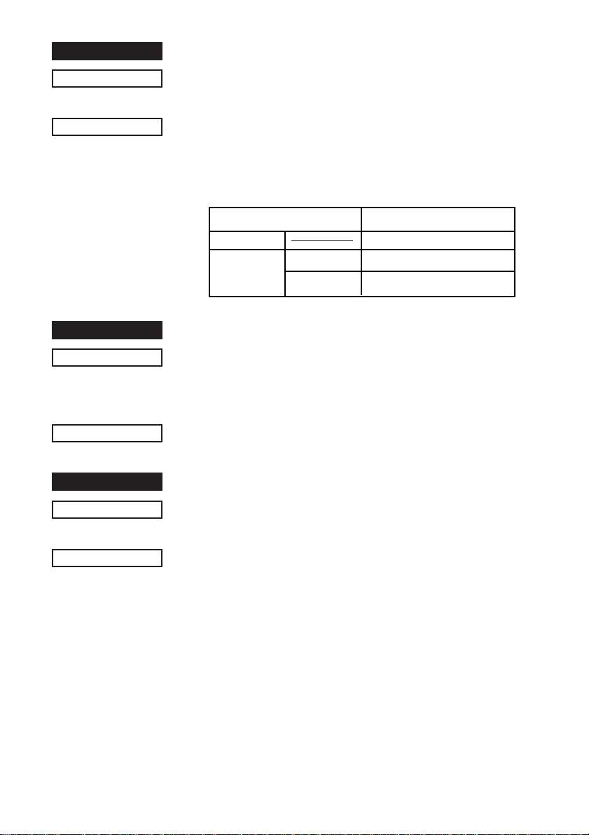
The <CR> code is valid when the memory switch 3-1 = 1 (set to 0
at exfactory). When the <CR> code is valid, setting the memory
switch 3-0 will cause the <CR> to function as shown in the table
below.
Memory Switch Setting <CR> Code Function
MSW 3-1 = 0 Ignored (at exfactory)
MSW 3-1 = 1
Feed paper n lines
<ESC> "a"
(1B)H (61)H
<
<
1
n
127
=
=
After data in the line buffer is printed out, feeds the paper n lines.
Horizontal tab
MSW 3-0 = 0 Same as <LF>
MSW 3-0 = 1 Prints only. No paper feed
n
n
CODE
OUTLINE
<HT>
(09)H
The print position skips to the next horizontal tab position in line.
If the current position is after the final horizontal tab position that
can be executed, this code is ignored. (Underlining and overlining
do not take place in the spaces between characters set with the
horizontal tab function.)
18
Page 21
FUNCTION
Define n/72-inch line spacing
CODE
DEFINITION RANGE
OUTLINE
FUNCTION
CODE
OUTLINE
FUNCTION
CODE
OUTLINE
<ESC> "A"
(1B)H (41)H
<
0
=
Line feed is defined at n/72-inch after this code is received.
This code sets the feed at n/72-inch with the <ESC> "2" code.
Set n/72-inch line spacing
<ESC> "2"
1B)H (32)H
This code sets the line feed at a defined value with the <ESC>
"A" previously described. Line feed pitch is 1/6 inch when <ESC>
"A" n is not set.
Sets line spacing to 1/12-inch
<ESC> "z" "0" or <ESC> "z" <0>
(1B)H (7A)H (30)H or (1B)H (7A)H (00)H
Line feed is set at 1/12-inch after this code is received.
n
n
<
n
85 (Default n = 12)
=
FUNCTION
CODE
OUTLINE
FUNCTION
CODE
OUTLINE
Sets line spacing to 1/6-inch (Default)
<ESC> "z" "1" or <ESC> "z" <1>
(1B)H (7A)H (31)H or (1B)H (7A)H (01)H
Line feed is set at 1/6-inch after this code is received.
Sets line spacing to 1/8-inch
<ESC> "0"
(1B)H (30)H
Line feed is set at 1/8-inch after this code is received.
19
Page 22
FUNCTION
Sets line spacing to 7/72 inch
CODE
OUTLINE
FUNCTION
CODE
DEFINITION RANGE
OUTLINE
FUNCTION
CODE
DEFINITION RANGE
OUTLINE
<ESC> "1"
(1B)H (31)H
Line feed is set at 7/72-inch after this code is received.
One time n/72-inch feed
<ESC> "J"
(1B)H (4A)H
1
This code activates the n/72-inch paper feed once.
Sets line spacing to n/216-inch approximately
<ESC> "3"
(1B)H (33)H
1
Setting value is approximated using the following equation
because the minimum pitch of the paper feed mechanism is 1/
144 inch.
INT (n X 2/3 + 0.5)/144 inches
n
n
<
<
n
255
=
=
n
n
<
<
n
255
=
=
FUNCTION
CODE
DEFINITION RANGE
OUTLINE
Sets line spacing to n/144-inch
<ESC> "y"
(1B)H (79)H
1
Line feed is set at n/144-inch after this code is received.
Default is n = 24.
n
n
<
<
n
255
=
=
20
Page 23

FUNCTION
Sets horizontal tab stops
CODE
DEFINITION RANGE
OUTLINE
FUNCTION
CODE
OUTLINE
<ESC> "D"
(1B)H (44)H
<
1
=
<
1
=
Cancels all horizontal tab stops and sets new tab stops within the
character pitch at
stops (1
stops must be set in ascending order. If tab stops are set in an
order which differs fro this, it will end. A <0> code is added as the
ending edge. All tab stops are cleared by inputting <ESC> "D"
<0>. The reference point for the tab positions is left edge of the
paper, regarless of the settings for the left margin. When you
turn ON the power, the horizontal tabs are not set.
Sets left margin
<ESC> "l"
1B 6C
Sets the non-printable range with the current character pitch up to
the nth postion with the left edge as the reference, after printing
the data in the line buffer.
Settings changed partway through a line take effect from the
subsequent line. Changing the character pitch after setting does
not change the left margin. The left margin is the left edge is
when the power is turned ON.
The left margin must be at least 18 dots within the following
values in the left edge of the right margin. Also, if there is less
than one character including the space between characters in the
printable range set for the left and right margins, a "?" will be
printed instead of the character because printing is not possible
there.
The range of n is 0
is n = 0.
n1
k
n1 n2
...nk <0>
n1 n2
...nk (00)H
<
<
n2
n3
=
=
<
16
=
n1, n2
<
<
n1
n2
=
=
<
... <
nk
(Maximum print columns -1),
=
, etc. You can set up to 16 individual tab
<
n3
=
...n16
<
maximum printing digits). Tab
=
n
n
<
<
n
(right margin -2)
=
=
<
255. The default
=
21
Page 24

FUNCTION
Sets right margin
CODE
OUTLINE
<ESC> "Q"
1B 51
Sets the non-printable range with the current character pitch up to
the nth postion with the left edge as the reference, after printing
the data in the line buffer.
Settings changed partway through a line take effect from the
subsequent line. Changing the character pitch after setting does
not change the right margin. The right margin is the right edge is
when the power is turned ON.
The right margin must be at least 18 dots within the following
values. Also, if there is less than one character including the
space between characters in the printable range set for the left
and right margins, a "?" will be printed instead of the character
because printing is not possible there.
The range of n is 2
<
255. The default is n = maximum number of printable digits>.
=
n
n
<
<
n
<maximum number of printable digits>
=
=
22
Page 25
FUNCTION
Aligns position
CODE
OUTLINE
<ESC> <GS> "a"
(1B)H (1D)H (61)H
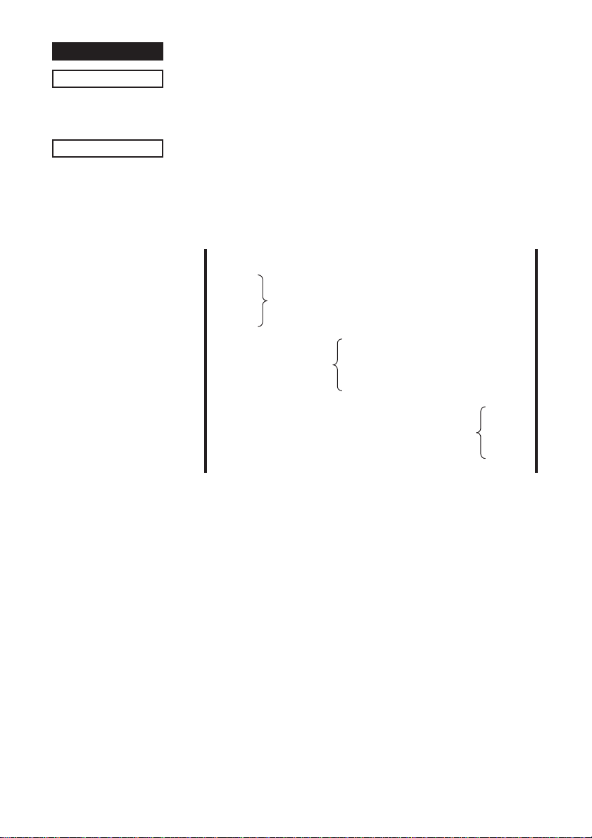
Sets the alignment of the positions.
Aligns all print data of one line to the specified position.
n = (00)H, "0": Left edge alignment (default)
(01)H, "1": Center alignment
(02)H, "2": Right edge alignment
ABC
ABCD
ABCDE
<ESC> <GS> “a” “1”
n
n
<ESC> <GS> “a” “0”
ABC
ABCD
ABCDE
<ESC> <GS> “a” “2”
ABCDE
ABC
ABCD
Note:
• Effective only when input at the beginning of the line.
• Align positions within the printable range that has been set.
• Skipped areas by the horizontal tab are also targeted for
position alignment.
23
Page 26
FUNCTION
Sets vertical tab stops
CODE
DEFINITION RANGE
OUTLINE
NOTE
<ESC> "B"
(1B)H (42)H
<
1
=
Cancels all current vertical tab stops and sets new vertical tab
stops at lines
between 1 and 255. A maximum number of 16 vertical tab
positions can be set. Tab positions must be specified in
ascending order; any violation of ascending order terminates the
tab position list. Standard termination is by the <0> control code.
Vertical tab positions are set in terms of the current line spacing
and do not move if the line spacing is changed later.
If a tab set position <nk> is equivalent or smaller than <nk -1> just
preceding the tab set position, setting of vertical tab is assumed
as complete.
n1
<
=
n2
n1 n2
n1 n2
<
=
n1, n2
...nk <0>
...nk (00)H
n3
... <
, etc. where
nk
<
=
255
n1, n2
<
<
<
1
k
=
, etc. are numbers
16
=
=
24
Page 27
1-2-3. Dot Graphics Control
FUNCTION
CODE
DEFINITION RANGE
OUTLINE
EXAMPLE
8 dot normal density graphics
<ESC> "K"
(1B)H (4B)H
<
1
=
n1
<0>
m1 m2
n1
(00)H
m1 m2
<
n1
200 (DIP SW 1 - 5 = ON) or 1
=
...
...
<
<
n1
210 (DIP SW =
=
=
OFF)
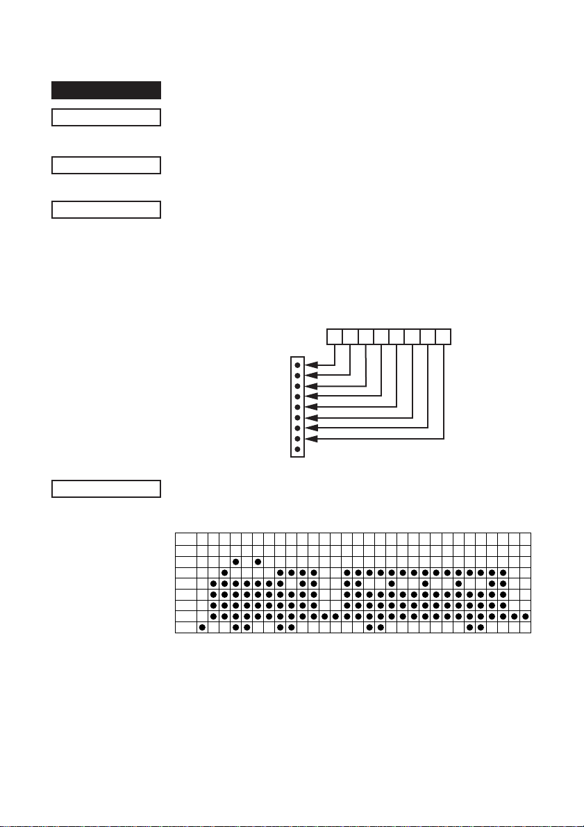
Executes 8 dot bit image print determined by "n1." The total
number of bit image data bytes in one line is equal to
n1
. Printing
is uni-directional. The printer ignores any data bytes over the
specified amount allowed in one line. When the bit image print is
finished the printer automatically returns to the character mode.
Image data
MSB
D8 D7 D6 D5 D4 D3 D2 D1
Dot Position
Not Used
LSB
Actually, let us consider printing as a means of bit image. We will
create the design below using bit image.
m1 m2 m3 m4 m5 m6 m7 m8 m9
D
8
D
7
D
6
D
5
D
4
D
3
D
2
D
1
m10 m11m12m13m14 m15 m16 m17 m18 m19 m20m21m22 m23 m24 m25 m26 m27 m28 m29m30
25
Page 28
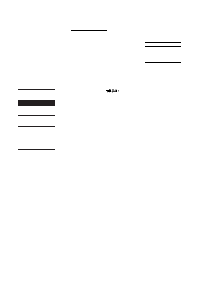
First, since the volume of data is 30,
n1
= (1E)H. If the data m1 to
m30 is converted to hexadecimal, it appears as shown below.
Print Sample
FUNCTION
CODE
DEFINITION RANGE
OUTLINE
Data Binary Hex
m1
00000001 01
m2
00011110 1E
m3
00111110 3E
m4
01011111 5F
m5
00011111 1F
m6
01011110 5E
m7
00011110 1E
m8
00111111 3F
m9
00101111 2F
m10
00111110 3E
Data Binary Hex
m11
00111110 3E
m12
00000010 02
m13
00000010 02
m14
00111110 3E
m15
00111110 3E
m16
00101111 2F
m17
00101111 2F
m18
00111110 3E
m19
00101110 2E
m20
00101110 2E
Data Binary Hex
m21
00111110 3E
m22
00101110 2E
m23
00101110 2E
m24
00111110 3E
m25
00101111 2F
m26
00101111 2F
m27
00111110 3E
m28
00111110 3E
m29
00000010 02
m30
00000010 02
8 dot high density graphics
<ESC> "L"
(1B)H (4C)H
<
1
=
<
1
=
n1
n1
n1 n2
n1 n2
+ 256 X
+ 256 X
m1 m2...
m1 m2...
<
n2
420 (DIP SW 1-5 = ON))
=
<
n2
400 (DIP SW 1-5 = OFF)
=
Executes double density bit image printing (half-dot printing)
determined by "n1" and "n2". The total number of bit image data
bytes in one line is equal to
n1 + n2
X 256. Refer to <ESC> K as
to the relation between the dot position and the bit number. The
printer ignores any data bytes over the specified amount allowed
in one line. Pringing is uni-directional.
The printer does not print adjacent dots. When the bit image
printing is finished, the printer automatically returns to the
character mode.
26
Page 29
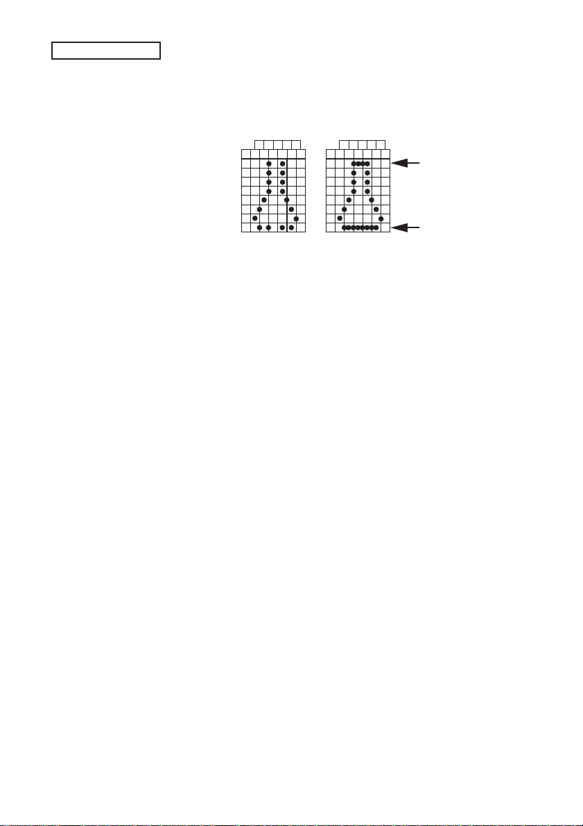
NOTE
For double density bit image printing, dots cannot be printed
overlapping each other in the horizontal direction.
The following is an example of this.
Printing possible Printing not possible
m2 m4m6
m8
m3 m5m7
m10
m9
m11
m1
D8
D7
D6
D5
D4
D3
D2
D1
D8
D7
D6
D5
D4
D3
D2
D1
m2 m4m6
m1
m3 m5m7
m8
m10
m9
m11
Overlapping
horizontally
Overlapping
horizontally
When printing one graphic image of a minimum of two lines with
<ESC> K or <ESC>L, feed the paper a minimum of one line
before printing so that the line spacing becomes identical
between the lines.
27
Page 30
1-2-4. Download Graphics Printing
FUNCTION
CODE
DEFINITION RANGE
OUTLINE
Dot Position
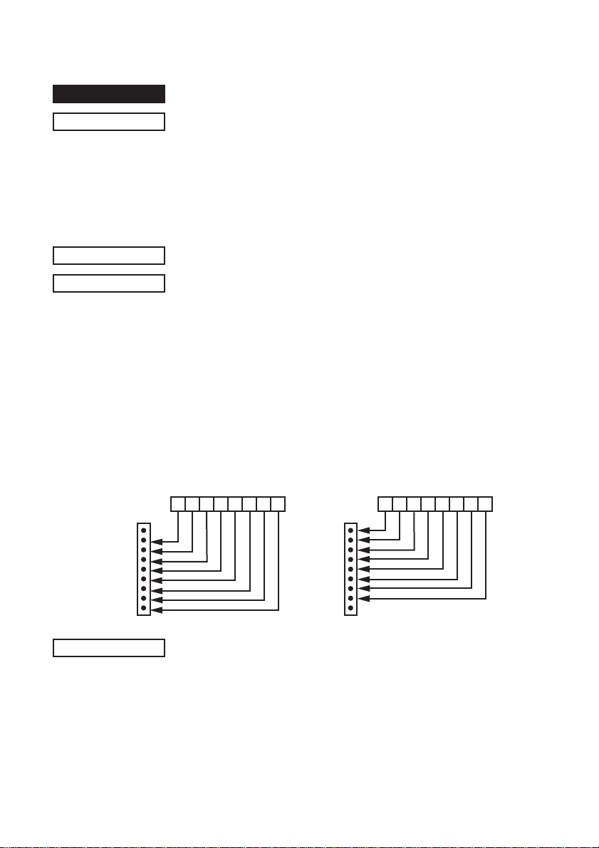
Defines download characters
When the 7 X 9 (half dot) font is set (default setting):
<ESC> "&" <0>
(1B)H (26)H (00)H
n1 n2
[m0 m1 m2 m3 m4 m5 m6 m7]
n1 n2
[m0 m1 m2 m3 m4 m5 m6 m7]
When the 5 X 9 font is set:
<ESC> "&" <0>
(1B)H (26)H (00)H
<
(21)H
=
n1
n1 n2
[m0 m1 m2 m3 m4 m5]
n1 n2
[m0 m1 m2 m3 m4 m5]
<
n2
(7F)H, m0 = (00)H or m0 = (80)H
=
Defines download characters
Up to 10 download characters can be defined and the defined
character patterns can be stored in the printer's RAM.
Defining of download characters begins with character code
and completes with
n2
.
n2
. When only one character is defined,
m0 indicates the relationship between the character pattern and
print head.
m1 = m2...Indicate the character pattern
WHEN m0 = (00)H WHEN m0 = (80)H
MSB
D8 D7 D6 D5 D4 D3 D2 D1
Not
Used
LSB
Dot Position
MSB LSB
D8 D7 D6 D5 D4 D3 D2 D1
n2 - n1
n2 - n1
n2 -
n2 -
+ 1
n1
+ 1
n1
+ 1
n1
n1
+ 1
=
NOTE
Not Used
When the 7 X 9 (half dot) font is set (the default setting), printing
of adjacent horizontal dots is not allowed.
28
Page 31
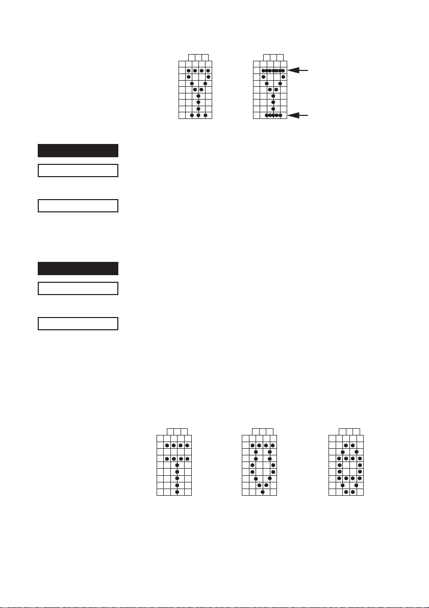
Printing possible Printing not possible
D8
D7
D6
D5
D4
D3
D2
D1
m2 m4m6
m3 m5m7
m1
D8
D7
D6
D5
D4
D3
D2
D1
m2 m4m6
m1
m3 m5m7
Overlapping
horizontally
Overlapping
horizontally
FUNCTION
CODE
OUTLINE
FUNCTION
CODE
OUTLINE
Enables download character set
<ESC> "%" "1" or <ESC> "%" <1>
(1B)H (25)H (31)H or (1B)H (25)H (01)H
Enables the download character set
Download characters defined by the ESC & 0 code cannot be
printed until enabled by this command.
Disables download character set (Default)
<ESC> "%" "0" or <ESC> "%" <0>
(1B)H (25)H (30)H or (1B)H (25)H (00)H
Disables the selected download character set and selects the
built-in character set. When the power of the printer is initially
turned on, the built-in character set is selected.
To pr int a download character when the 7
<
9 (half dot) font
=
character size is set.
(1) Design the download character to be used at code positions
(21)H, (22)H, and (23)H.
D8
D7
D6
D5
D4
D3
D2
D1
m2 m4m6
m1
m3 m5 m7
D8
D7
D6
D5
D4
D3
D2
D1
m2 m4m6
m3 m5m7
m1
D8
D7
D6
D5
D4
D3
D2
D1
m2 m4m6
m3 m5m7
m1
Char. Code = (21)H Char. Code = (22)H Char. Code = (23)H
29
Page 32
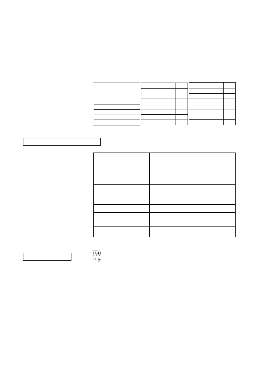
EXAMPLE of transmitting data
(2) Define the download characters.
When character codes where the download character is written
are specified as (21)H, (22)H, (23)H,
n1
= (21)H,
n2
= (23)H are
obtained.
If the relationship between the character pattern data and printing
head is specified to "not use pin 9", m0 = (80)H is obtained.
When data m1 to m7 are converted into hexadecimal data, they
are indicated as follows.
Data Binary Hex
m1
10100000 A0
m2
00000000 00
m3
10100000 A0
m4
00011111 1F
m5
10100000 A0
m6
00000000 00
m7
10100000 A0
(1) Definition of (1B)H (26)H (00)H (21)H (23)H (80)H
download characters (A0)H (00)H (A0)H (1F)H (A0)H (00)H
(2) Selecting the (1B)H (25)H (31)H
download character
set
(3) Character codes (21)H (22)H (23)H (0A)H
(4) Canceling the (1B)H (25)H (30)H
download character set
(5) Character codes (21)H (22)H (23)H (0A)H
Data Binary Hex
m1
10011000 98
m2
01100100 64
m3
10000010 82
m4
00000001 01
m5
10000010 82
m6
01100100 64
m7
10011000 98
(A0)H (80)H (98)H (64)H (82)H (01)H
(82)H (64)H (98)H (80)H (3C)H (42)H
(A5)H (00)H (A5)H (42)H (3C)H
Data Binary Hex
m1
00111000 3C
m2
01000010 42
m3
10100101 A5
m4
00000000 00
m5
10100101 A5
m6
01000010 42
m7
00111000 3C
Print Sample
30
Page 33
1-2-5. Peripheral Device Control
FUNCTION
CODE
DEFINITION RANGE
OUTLINE
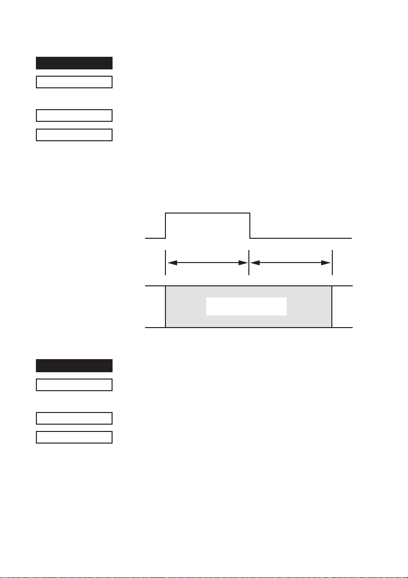
Defines drive pulse width for peripheral device #1
<ESC> <BEL>
(1B)H (07)H
<
1
n1
=
Adjusts drive pulse width for peripheral devices requiring other
than standard 200 ms pulse time and delay time
Energizing time = 10 X
Delay time = 10 X
Executed by <BEL>, <FS> codes.
n1 n2
n1 n2
<
=
<
127, 1
10 x n1 (ms) 10 x n2 (ms)
<
n2
127 (default setting
=
=
n1
(ms)
n2
(ms)
Printing and paper
feed are prohibited.
n1 = n2
= 20)
FUNCTION
CODE
OUTLINE
NOTE
Controls peripheral device #1
<BEL>
(07)H
Executes drive pulse for peripheral unit 1 (deferred).
Peripheral Units 1 and 2 cannot be driven simultaneously.
31
Page 34
FUNCTION
Controls peripheral device #1 immediately
CODE
OUTLINE
NOTE
FUNCTION
CODE
OUTLINE
NOTE
<FS>
(1C)H
Executes drive pulse for peripheral unit 1 (immediate).
This code differs from the <BEL> code as follows:
When the printer receives an <FS> code, the command is
executed immediately. The <BEL> code is stored in the data
buffer in the same manner as other codes, and executed in the
order in which they are received.
Immediate drive command for peripheral unit 2
Peripheral Units 1 and 2 cannot be driven simultaneously.
Controls peripheral device #2 immediately
<EM>
(19)H
Drives peripheral unit 2. Pulse width is fixed at 200 ms with a
fixed delay time of 200 ms.
When the printer receives a <EM> code, the command is
executed immediately. Same as <SUB>.
Peripheral Units 1 and 2 cannot be driven simultaneously.
FUNCTION
CODE
OUTLINE
NOTE
Controls peripheral device #2 immediately
<SUB>
(1A)H
Drives peripheral unit 2. Pulse width is fixed at 200ms with a fixed
delay time of 200 ms.
When the printer receives a <SUB> code, the command is
executed immediately. Same as <EM>
Peripheral Units 1 and 2 cannot be driven simultaneously.
32
Page 35
1-2-6. Auto Cutter Control (SP2500 type printers only)
FUNCTION
CODE
OUTLINE
FUNCTION
CODE
OUTLINE
FUNCTION
CODE
Full-cut command to the auto cutter
<ESC> "d" "0" or <ESC> "d" <0>
(1B)H (64)H (30)H or (1B)H (64)H (00)H
Full cut command. Executes a full cut after printing the data in
the line buffer.
This command is valid only on SP2520/SP2560 series printers
and is ignored on SP2320/SP2360 series printers.
Partial-cut command to the auto cutter
<ESC> "d" "1" or <ESC> "d" <1>
(1B)H (64)H (31)H or (1B)H (64)H (01)H
Partial cut command. Executes a partial cut after printing the
data in the line buffer.
This command is valid only on SP2520/SP2560 series printers
and is ignored on SP2320/SP2360 series printers.
Full-cut command to the auto cutter after paper feed
<ESC> “d” “2” or <ESC> “d” <2>
(1B)H (64)H (32)H or (1B)H (64)H (02)H
OUTLINE
Paper feed + full cut command
Executes the following actions after printing the data in the line
buffer.
(SP2520/2560) Feeds paper to the cutting position and executes
a full cut (Note 1).
(SP2320/2360) Feeds paper to the tear bar position (Note 2).
Note 1: Paper feed to cut position: Executed in 1 inch units.
Note 2: Paper feed to tear bar position: Executed in 7/6 inch
units.
33
Page 36

FUNCTION
Partial-cut command to the auto cutter after paper feed
CODE
OUTLINE
<ESC> “d” “3” or <ESC> “d” <3>
(1B)H (64)H (33)H or (1B)H (64)H (03)H
Paper feed + full cut command
Executes the following actions after printing the data in the line
buffer.
(SP2520/2560) Feeds paper to the cutting position and executes
a full cut (Note 1).
(SP2320/2360) Feeds paper to the tear bar position (Note 2).
Note 1: Paper feed to cut position: Executed in 1 inch units.
Note 2: Paper feed to tear bar position: Executed in 7/6 inch
units.
34
Page 37
1-2-7. Command to Set the Page Format
FUNCTION
CODE
DEFINITION RANGE
OUTLINE
FUNCTION
CODE
DEFINITION RANGE
OUTLINE
FUNCTION
CODE
DEFINITION RANGE
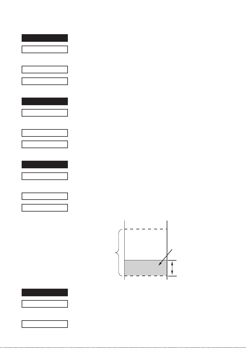
Set page length in n lines
<ESC> “C”
(1B)H (43)H
<
1
=
Sets page length in n lines.
Set page length in n inches
<ESC> “C” <0>
(1B)H (43)H (00)H
<
1
=
Sets page length in n inches.
Set bottom margin
<ESC> “N”
(1B)H (4E)H
<
0
=
n
n
<
n
255 (default: n =42)
=
n
<
n
127
=
n
n
<
n
255 (Default n = 0)
=
n
OUTLINE
FUNCTION
CODE
OUTLINE
Sets bottom margin to n lines.
Page length
Cancel bottom margin (Default)
<ESC> “O”
(1B)H (4F)H
Cancels bottom margin.
35
Feeds the paper
automatically
Bottom margin
of
n
lines
Page 38
1-2-8. Other Commands
FUNCTION
CODE
OUTLINE
Print Sample
CODE
OUTLINE
FUNCTION
CODE
Cancels printer buffer & Initialize printer
<CAN>
(18)H
Clears the data buffer and line buffer and initializes all commands
that have already been set. <CAN> is executed not when taking
data from the reception buffer, but when it is received from the
host. The select/deselect states in the DC1 and DC3 modes, and
external device drive conditions set by <ESC> <BEL>
do not affect the automatic status valid/invalid conditions.
Deselects printer
<DC3>
(13)H
Data following this code is ignored when the printer receives a
<DC3> code.
The deselect mode is canceled by <DC1> code.
Set select mode (Default)
<DC1>
(11)H
n1
and
n2
OUTLINE
FUNCTION
CODE
OUTLINE
When the printer receives a <DC1> code, the deselect mode is
canceled and data following this code is input to the buffer.
Beeps the buzzer
<RS>
(1E)H
A short alarm is generated by the printer.
36
Page 39
FUNCTION
Sets the memory switch
CODE
HEX
OUTLINE
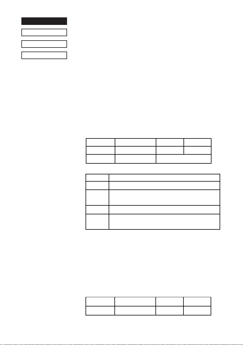
<ESC> “# N,
1B 23 N 2C
In order to enable changed memory switch settings, turn the
printer OFF and ON again or send the printer reset command
(<ESC> “?” <LF> <NUL>) to the printer. Changed memory
switch settings are stored in EEPROM and these settings will be
stored until they are changed again.
N: Memory switch number (“0,” “1,” “2,” “3,” “4,” “5,” “6”)
n1 n2 n3 n4
1) N = 0 (Star mode)
Parameter Setting “0” (Default) “1”
n3
n4
n4 <FF> command *1
“0” to “3” Feeds page
“4” to “7” Executes full cut after feeding paper to the cut
“8” to “B” Feeds page
“C” to “F” Executes partial cut after feeding paper to the cut
n1 n2 n3 n4
n1 n2 n3 n4
: Mode settings (For details see below.)
n1
: Always “0”
n2
: Always “0”
Destination Standard Asia Market
FF command *1 See below
position. (*2)
position. (*2)
” <LF> <NUL>
0A 00
*1: Only on printers that have an auto-cutter (SP2520/2560).
*2: Paper feed to cutting position is executed in 1 inch incre-
ments.
N = 0 (ESC/POS mode)
n1
: Always “0”
n2
: Always “0”
n4
: Always “0”
Parameter Setting “0” (Default) “1”
n3
Destination Standard Asia Market
37
Page 40
2) N = 1 (Star mode only)
n1
: Always “0”
n2
: Always “0”
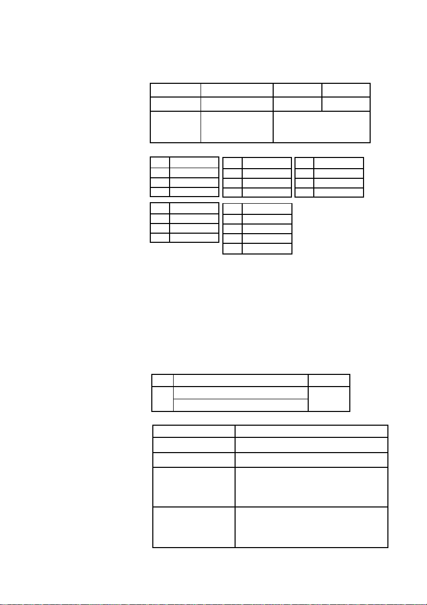
Parameter Setting “0” (Default) “1”
n3
n4
Zero style Normal Slashed
International See below
character set
n4 Country
“0” USA
“1” France
“2” Germany
n4 Country
“9” Norway
“A” Denmark #2
“B” Spain #2
n4 Country
“3” UK
“4” Denmark #1
“5” Sweden
n4 Country
“C” Latin America
“D” Korea
“E” Ireland
n4 Country
“6” Italy
“7” Spain #1
“8” Japan
“F” Legal
When memory switch N = 0, n3 = “0” (Destination is standard),
this setting is valid.
3) N = 2 (Star mode)
n1
: Always “0”
n2
: Always “0”
n3
: Always “0”
Para. Setting “0” to “F”
n4
Comdex Dual Auto Cut mechanism (*1) See below
Paper near end sensor
n4 Paper near end sensor
“0” or “4” or “8” or “C” Invalid
“1” or “9” or “D” Invalid
“2” or “A” or “E” Reflects status of sensor to STATUS
and when near end, does not go offline
and does not stop printing.
“3” or “B” or “F” Reflects status of sensor to STATUS
and when near end, goes offline and
stops printing.
38
Page 41
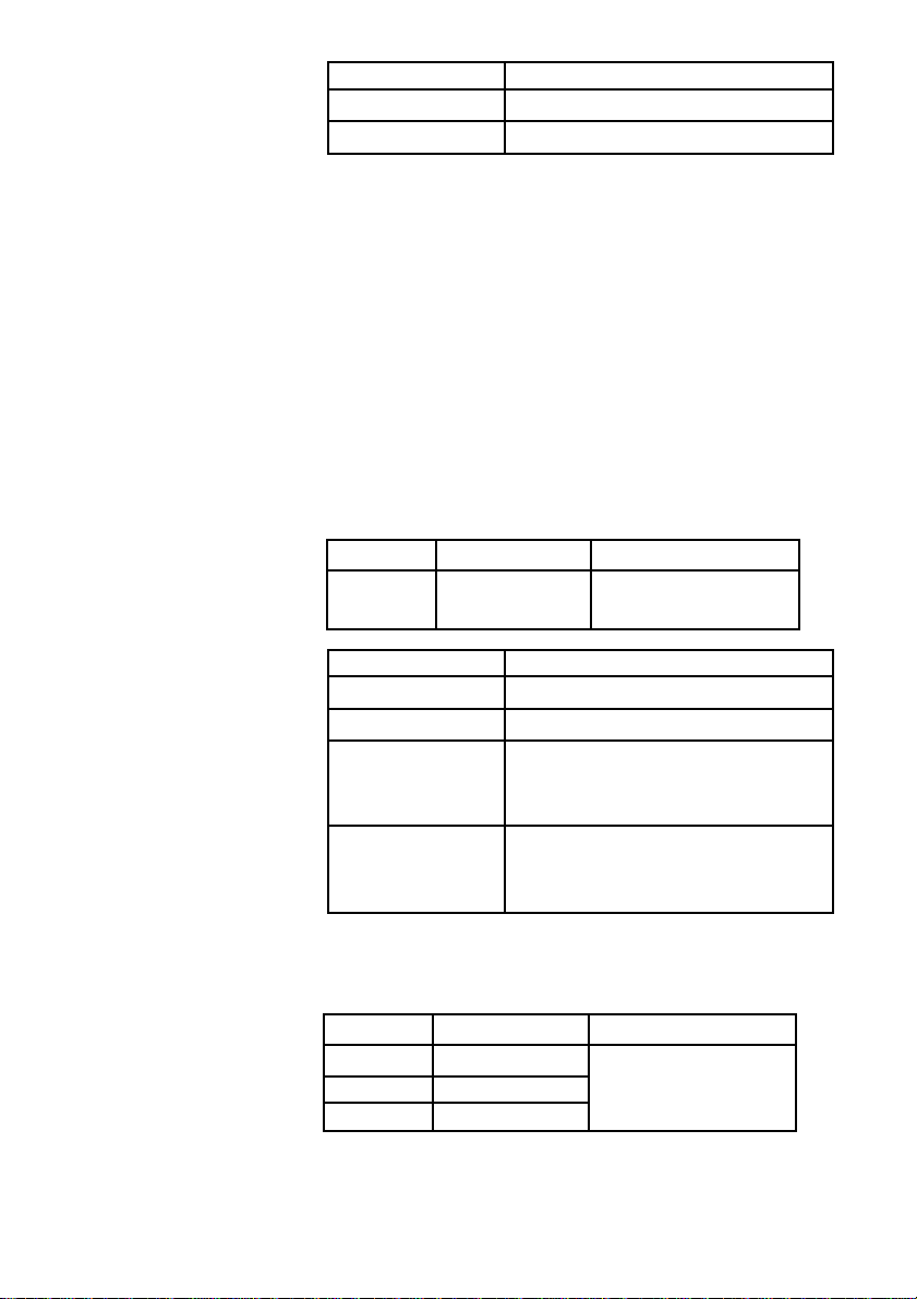
n4 Comdex dual auto-cutter
“0” to “7” Invalid
“8” to “F” Valid
*1: Comdex Dual Auto Cut Mechanism (STAR mode only)
This mechanism automatically cuts when there is a consecutive paper feed exceedin 7/6 inch. Hosts that cannot send an
escape sequence such as <ESC> “d” and 0, can cut the
paper if a line feed code <LF> of 1/6 inch is sent 7 times
consecutively.
N = 2 (ESC/POS mode)
n1
: Always “0”
n2
: Always “0”
n3
: Always “0”
Parameter Setting “0” to “F”
n4
n4 Paper near end sensor
“0” or “4” or “8” or “C” Invalid
“1” or “9” or “D” Invalid
“2” or “A” or “E” Reflects status of sensor to STATUS
“3” or “B” or “F” Reflects status of sensor to STATUS
Paper near end See below
sensor
and when near end, does not go offline
and does not stop printing.
and when near end, goes offline and
stops printing.
4) N = 3 (Star mode)
n3
: Always “0”
Parameter Setting “0” to “F”
n1
n2
n4
Character table
Character table See below
CR code
39
Page 42
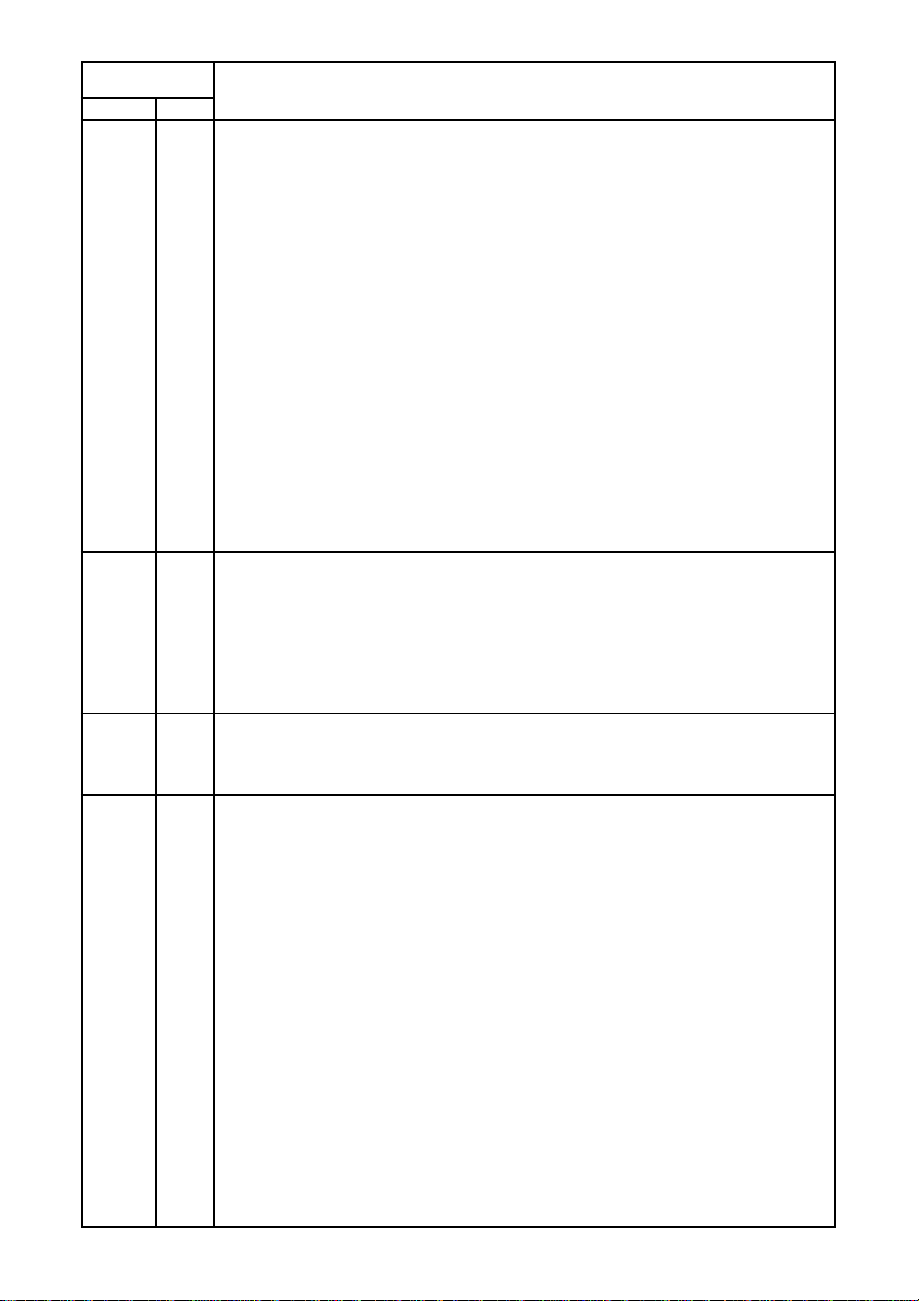
Value of
n1 n2
“0” or “8” “0” Normal (Default)
“0” or “8” “1” Code Page 437 (USA, Std. Europe)/IBM Character Set #2
“0” or “8” “2” Katakana
“0” or “8” “3” IBM Character Set #1
“0” or “8” “4” Codepage 858 (Multilingual)
“0” or “8” “5” Codepage 852 (Latin-2)
“0” or “8” “6” Codepage 860 (Portuguese)
“0” or “8” “7” Codepage 861 (Icelandic)
“0” or “8” “8” Codepage 863 (Canadian French)
“0” or “8” “9” Codepage 865 (Nordic)
“0” or “8” “A” Codepage 866 (Cyrillic Russian)
“0” or “8” “B” Codepage 855 (Cyrillic Bulgarian)
“0” or “8” “C” Codepage 857 (Turkish)
“0” or “8” “D” Codepage 862 (Hebrew)
“0” or “8” “E” Codepage 864 (Arabic)
“0” or “8” “F” Codepage 737 (Greek)
“1” or “9” “0” Codepage 851 (Greek)
“1” or “9” “1” Codepage 869 (Greek)
“1” or “9” “2” Codepage 928 (Greek)
“1” or “9” “3” Codepage 772 (Lithuanian)
“1” or “9” “4” Codepage 774 (Lithuanian)
“1” or “9” “5” Codepage 874 (Thai)
“2” or “A” “0” Codepage 1252 (Windows Latin-1)
“2” or “A” “1” Codepage 1250 (Windows Latin-2)
“2” or “A” “2” Codepage 1251 (Windows Cyrillic)
“4” or “C” “0” Codepage 3840 (IBM-Russian)
“4” or “C” “1” Codepage 3841 (Gost)
“4” or “C” “2” Codepage 3843 (Polish)
“4” or “C” “3” Codepage 3844 (CS2)
“4” or “C” “4” Codepage 3845 (Hungarian)
“4” or “C” “5” Codepage 3846 (Tur kish)
“4” or “C” “6” Codepage 3847 (Brazil-ABNT)
“4” or “C” “7” Codepage 3848 (Brazil-ABICOMP)
“4” or “C” “8” Codepage 1001 (Arabic)
“4” or “C” “9” Codepage 2001 (Lithuanian-KBL)
“4” or “C” “A” Codepage 3001 (Esornian-1)
“4” or “C” “B” Codepage 3002 (Esornian-2)
“4” or “C” “C” Codepage 3011 (Latvian-1)
“4” or “C” “D” Codepage 3012 (Latvian-2)
“4” or “C” “E” Codepage 3021 (Bulgarian)
“4” or “C” “F” Codepage 3041 (Maltese)
n
Character Table
40
Page 43
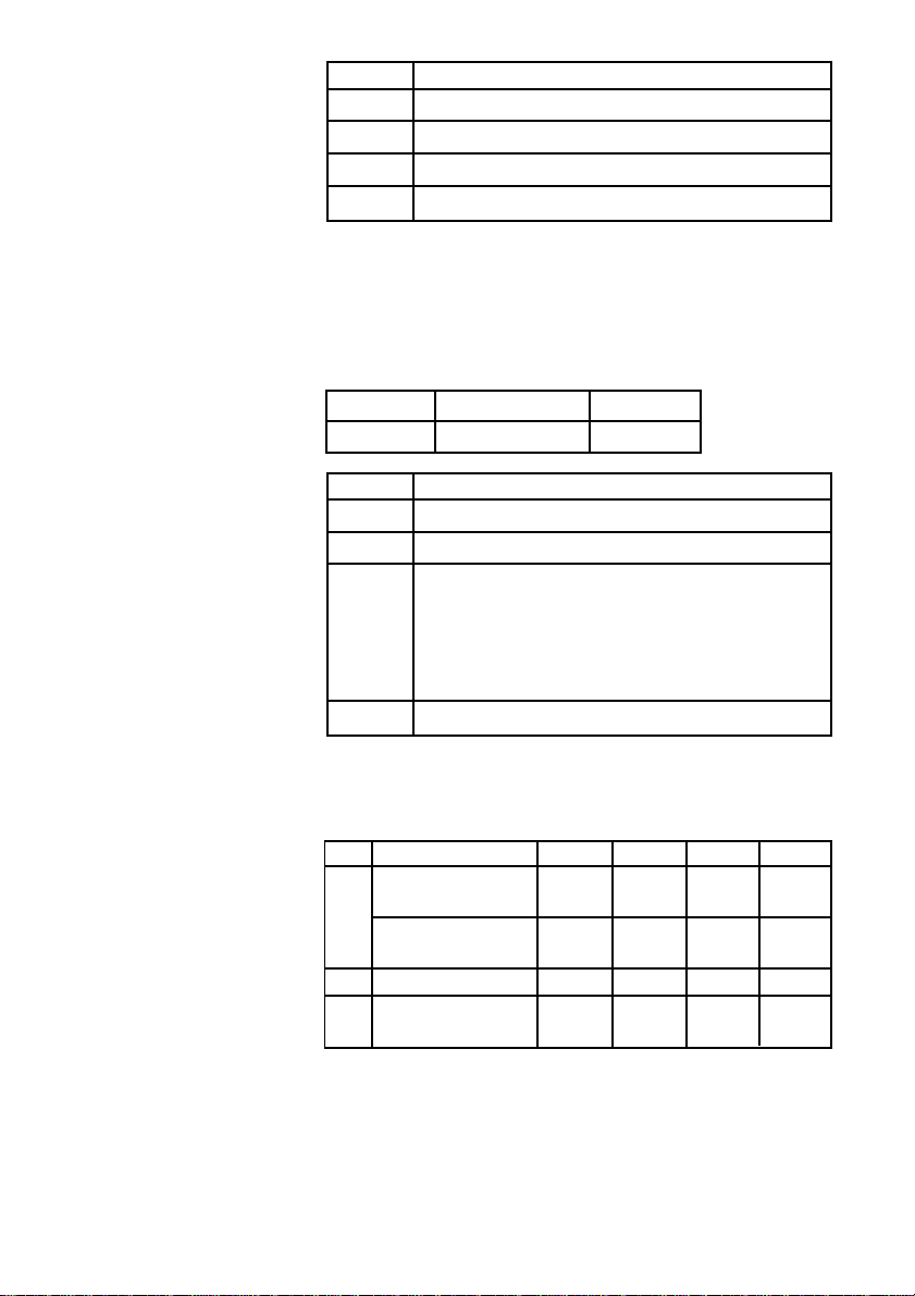
n4 CR code
“0” Ignores
“1” Ignores
“2” Feeds line after printing (same as <LF>
“3” Prints (no line feed.)
N = 3 (ESC/POS mode)
n1
: Always “0”
n2
: Always “0”
n3
: Always “0”
Parameter Setting “1” to “3”
n4
CR code See below
n4 CR code
“0” Prints (no line feed.)
“1” Feeds line after printing (same as <LF>
“2” (Parallel Interface)
Prints and feeds line when nAutoFd signal is “LOW”.
Does not feed line when “HIGH.”
(Serial Interface)
Ignores
“3” Ignores
5) N = 4 (Star mode)
n3
: Always “0”
Para. Setting “0” “1” “2” “3”
n1
X on/X off Timing When Every 3 When Every 3
Toggled sec Toggled sec
RTS Signal Condition Save as Save as Always Always
DTR DTR SPACE SPACE
n2
Receive buffer size 4 kbytes 4 kbytes 256 bytes 256 bytes
n4
Data receipt error “?” Ignored “?” Ignored
Printed Printed
41
Page 44
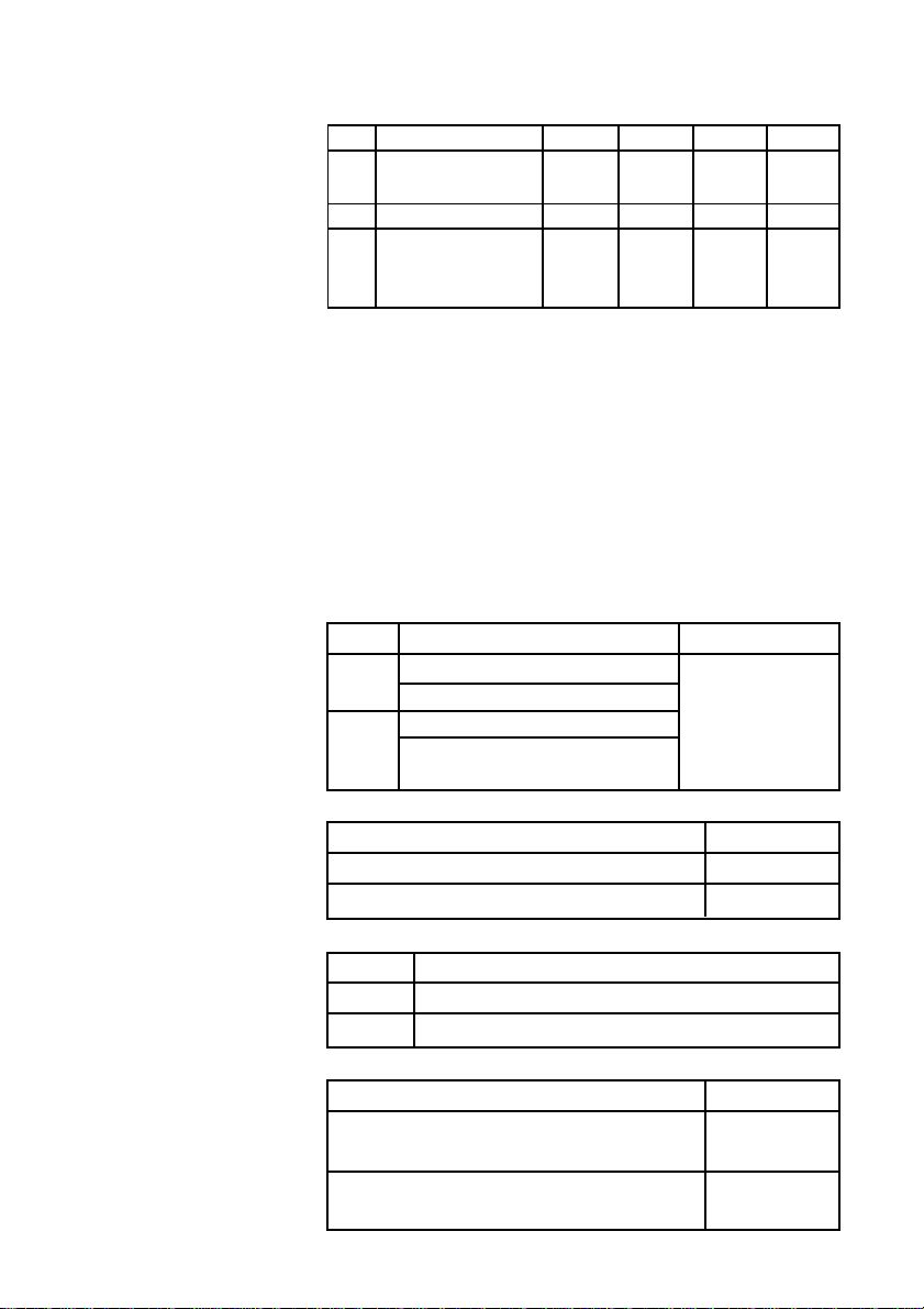
N = 4 (ESC/POS mode)
n3
: Always “0”
Para. Setting “0” “1” “2” “3”
n1
RTS signal condition Save as Save as Always Always
DTR DTR SPACE SPACE
n2
Receive buffer size 4 k bytes 4 k bytes 40 bytes 40 bytes
n3
DSR signal check Checked Checked Not Not
during setting status Checked Checked
transmission
6) N = 5
n1
: Always “0”
n2
: Always “0”
n3
: Always “0”
n4
: Always “0”
7) N = 6
n3
: Always “0”
n4
: Always “0”
Para. Setting “0” to “F”
n1
Device ID (Parallel I/F only)
nPError signal (Parallel I/F only)
n2
Busy condition (Star mode only) *1 See below
Treatment of missing data
during reverse mode.*2
n1 Device ID
“0” or “2” or “4” or “6” or “8” or “A” or “C” or “E” Invalid
“1” or “3” or “5” or “7” or “9” or “B” or “D” or “F” Valid
n1 nPError signal
“0” to “7” Paper end sensor
“8” to “F” Paper end sensor and+ Paper near end sensor
n2 Busy condition
“0” or “2” or “4” or “6” or “8” or “A” or “C” or “E”
“1” or “3” or “5” or “7” or “9” or “B” or “D” or “F”
Receive buffer
full or offline
Receive buffer
full
42
Page 45
n2 Treatment of missing data during reverse mode
“0” to “7” Store
“8” to “F” Delete
*1: Valid only when using a parallel interface.
Set DIP SW 1-2 if you are using a serial interface.
Also, the conditions for BUSY and the automatic status are
disregarded.
*2: Valid only when using a parallel interface.
For example, if you exit the reverse mode without the host
receiving the trailing data of the automatice status the
remainder of the status data will be handled as described
below.
Store: Stores the remaining data and transmits it at the
next time the reverse mode is entered. If the
automatic status occurs, the new status will be
transmitted after that remaining data.
Delete: Deletes the remaining data. It does not transmit
that data the next time the reverse mode is
entered. The new status data is transmitted from
the header field.
FUNCTION
CODE
OUTLINE
Initialize printer
<ESC> “@”
(1B)H (40)H
Initializes all the commands already set. However the following
parameters are not initialized: online switch valid/invalid
selection. Also, the line and data buffers are not cleared. The
DIP switches and the memory switches are not read in again.
The select/deselect state for addressable mode and DC1/DC3
mode is not affected.
43
Page 46
FUNCTION
Transmits EOT status
CODE
OUTLINE
<EOT>
(04)H
Transmits the EOT status of the printer to the host in real-time.
(Does not execute after taking fro reception buffer, but immediately upon receiving from the host.) It is in a “Data ready” state
when using a bi-directional parallel interface.
• When one <EOT> command is sent to the printer, it will not
send the next <EOT> command until the EOT status is
received.
• When using the <EOT> command, always set the automatic
status function to invalid.
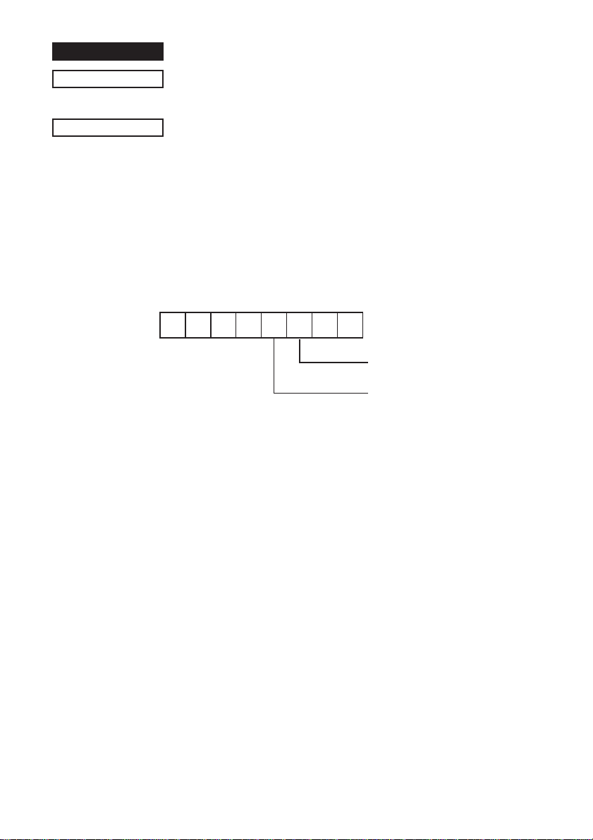
EOT Status
b7 b6 b5 b4 b3 b2 b1 b0
(Always 1)
Bit 2: Paper Near End
1: Near End
Bit 3: No Paper Error (Same as ENQ Bit 3)
1: Error
Bit1, Bit 5 to Bit 7 statsu unknown
44
Page 47
FUNCTION
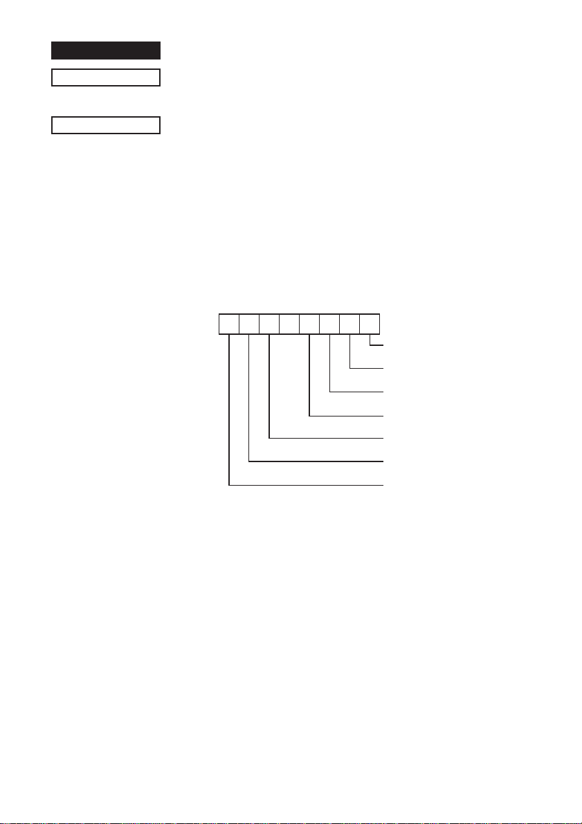
b7 b6 b5 b4 b3 b2 b1 b0
Bit 0: Parallel Error (*1)
1: Error
Bit 1: Framing Error (*1)
1: Error
Bit 2: Mechanical Error
1: Error
Bit 3: No Paper Error (Same as EOT Bit 3)
1: Error
Bit 5: Buffer Empty (*1)
1: Buffer "Empty
Bit 6: Buffer Overflow
1: Overflow
Bit 7: Compulsion SW (*2)
ENQ Status
Transmits ENQ status
CODE
OUTLINE
<ENQ>
(05)H
Transmits the ENQ status of the printer to the host in real-time.
(Does not execute after taking fro reception buffer, but immediately upon receiving from the host.) It is in a “Data ready” state
when using a bi-directional parallel interface.
• When one <ENQ> command is sent to the printer, it will not
send the next <ENQ> command until the ENQ status is
received.
• When using the <ENQ> command, always set the automatic
status function to invalid.
*1: Bit 0 and Bit 1 are valid only with a serial interface. Bit0 =
Bit1= 0 when using a parallel interface.
*2: Compulsion Switch
When the pin No. 6 on the connector for external device drive
circuit is HIGH (Switch ON), Bit 7 = 1.
45
Page 48
FUNCTION
Confirms finish of printing
CODE
OUTLINE
FUNCTION
CODE
OUTLINE
<ETB>
(17)H
This command cause the printer to wait until all printing is
completed (the printing motor stops) and sets the printer status 11 of the automatic status (<ETB> command) to “1” (only execute
ETB).
Also, if print data still remains in the line buffer, it executes this
command after printing the remaining data.
The host will know that the printing of the transmitted data is
completed by confirming that the bit is “1.” When the status bit is
cleared to “0” when returned to the host.
Transmits automatic status
<ESC> <ACK> <SOH>
(1B)H (06)H (01)H
This command transmirts the contents of the printer’s automatic
status one time. (When using a bi-directional parallel interface, it
is “Data Ready.”)
• When in the DTR mode for a serial interface, you need to set
DIP switch 1-3 to OFF so that the printer status can be inquired
during an error as well.
• When in the DTR mode for a parallel interface, you need to set
DIP switch 6-9 to “1” so that the printer status can be inquired
during an error as well.
• Always use the <ESC> <ACK> and <SOH> commands when
the automatic status function is set to invalid. Also, when the
<ESC> <ACK> and <SOH> commands are transmitted one
time, you must not send the next <ESC> <ACK> and <SOH>
commands until the automatic status is completely received.
46
Page 49
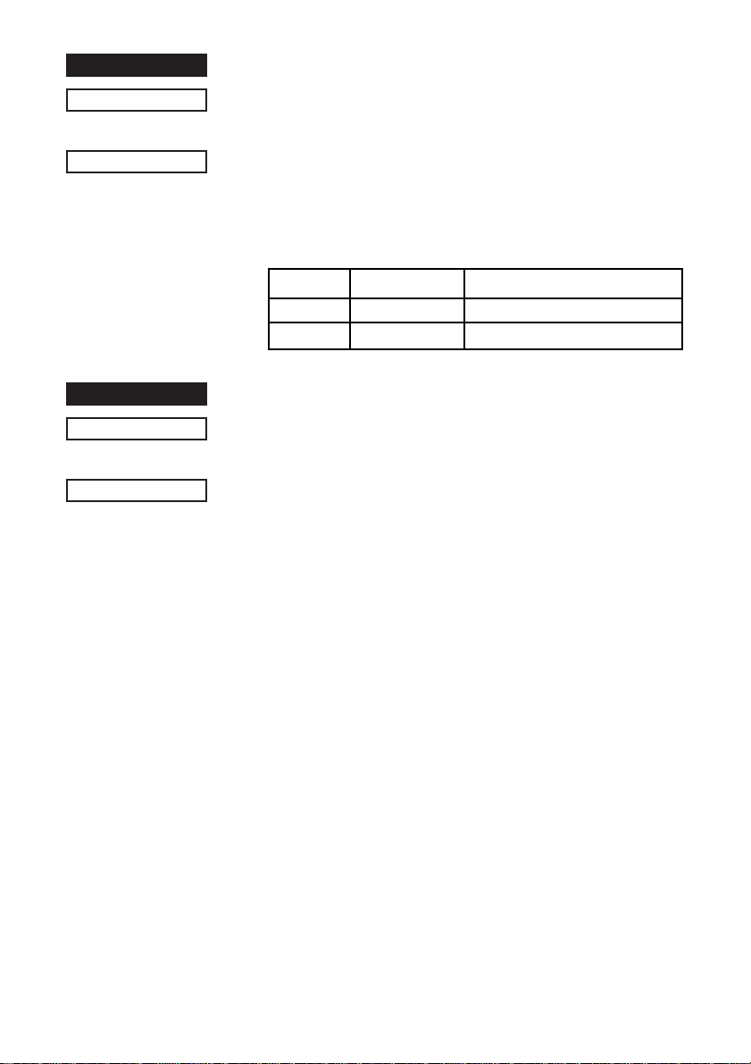
FUNCTION
Enables/disables automatic status
CODE
OUTLINE
FUNCTION
CODE
OUTLINE
<ESC> <RS> “a”
(1B)H (1E)H (61)H
This command sets the transmission conditions of the automatic
status. Initial values are according to DIP switch 1-6. See
Chapter 2 Automatic Status Specifications for details on the
contents of the automatic status.
Value of nHex Automatic Status Valid/Invalid
0 or “0” (00H) or (30H) Invalid
1 or “1” (01H) or (31H) Valid
Resets printer hardware and produces a test print
<ESC> “?” <LF> <NUL>
(1B)H (3F)H (0A)H (00)H
Resets the printers hardware and executes one self-test print.
After this command is sent, the next data is not sent until the
printer is confirmed to be back online.
n
n
47
Page 50
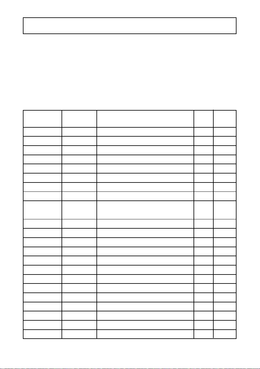
2. ESC/POS Mode Commands
The following table lists the TM-U200 and TM-U300 emulation commands that
are supported by this printer.
2-1. Control Codes List
Control Hexadecimal Function TM- TMCodes Codes U200 U300
<HT> 09 Horizontal tab OK OK
<LF> 0A Line feed OK OK
<CR> 0D Prints and carriage return OK OK
<DLE> <EOT> 10 04 Enables real-time status send OK
<DLE> <ENQ> 10 05 Real-time request to printer OK
<ESC> SP 1B 20 Sets size of space to right of character OK OK
<ESC> ! 1B 21 Enables batch print mode OK OK
<ESC> # 1B 23 Sets memory switch
<ESC> % 1B 25 Enables/disables download OK OK
character set
<ESC> & 1B 26 Defines download character OK OK
<ESC> * 1B 2A Selects bit image mode OK OK
<ESC> - 1B 2D Selects/cancels underlining OK OK
<ESC> 2 1B 32 Selects 1/6-inch line spacing OK OK
<ESC> 3 1B 33 Selects n/144-inch line spacing OK OK
<ESC> = 1B 3D Selects peripheral device OK
<ESC> ? 1B 3F Cancels download character OK OK
<ESC> @ 1B 40 Initializes the printer OK OK
<ESC> D 1B 44 Sets horizontal tab position OK OK
<ESC> E 1B 45 Enables/disables emphasized mode OK OK
<ESC> G 1B 47 Enables/disables double-strike mode OK OK
<ESC> J 1B 4A Prints and n/144-inch paper feed OK OK
<ESC> K 1B 4B Prints and n/144-inch reverse paper feed OK OK
48
Page 51
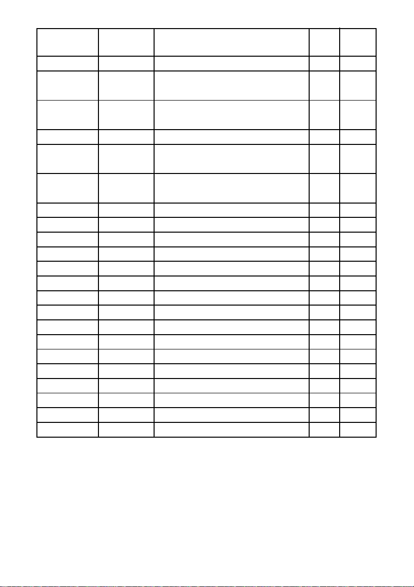
Control Hexadecimal Function TM- TMCodes Codes U200 U300
<ESC> R 1B 52 Selects international character set OK OK
<ESC> U 1B 55 Selects/cancels unidirectional OK OK
printing mode
<ESC> V 1B 56 Designates/cancels 90° character
rotation
<ESC> a 1B 61 Aligns position OK
<ESC> c 3 1B 63 33 Selects the paper-end sensor for OK OK
sending the no-paper signal
<ESC> c 4 1B 63 34 Selects the paper-end sensor for OK OK
stopping printing
<ESC> c 5 1B 63 35 Enables/disables control panel switches OK OK
<ESC> d 1B 64 Prints or feeds n lines OK OK
<ESC> e 1B 65 Prints or reverse feeds n lines OK OK
<ESC> i 1B 69 Full-cut command to the auto cutter OK
<ESC> m 1B 6D Partial-cut command to the anto cutter OK
<ESC> p 1B 70 Generates specified pulse OK OK
<ESC> r 1B 72 Selects print color OK
<ESC> t 1B 74 Selects character code table OK OK
<ESC> u 1B 75 Sends peripheral status OK
<ESC> v 1B 76 Sends paper sensor status OK
<ESC> { 1B 7B Enables/disables inverted printing OK OK
<GS> I 1D 49 Sends printer ID OK
<GS> V 1D 56 Cut command to the auto cutter OK
<GS> a 1D 61 Enables/disables automatic status OK
<GS> r 1D 72 Sends printer status OK
<GS> z 0 1D 7A 30 Setting of on-line recovery wait time OK
49
Page 52

Ignored Commands
Control Hexadecimal Function TM- TMCodes Codes U200 U300
<ESC> < 1B 3c Ignored (Returns home) OK
<ESC> c 0 n1B 63 30
<ESC> f t1 t2 1B 66 t1 t2 Ignored (Sets cut sheet wait time) OK
<GS> E n 1D 45 n Ignored (Selects head control method) OK
n
Ignored (Selects paper type(s) for printing) OK
50
Page 53

3. Auto Status Specifications
3-1. Auto Status
Auto status is a function that automatically relays any changes that occur in
the status of the printer from the printer to the host. It is composed of the
“Header -1,” “Header - 2” and “a plurality of bytes of printer states.”
The host always identifies the data using the method of identification for each
byte received. (For example: This is necessar y in consideration of the
receiving side because there is the possibility that the X on/X off code could
be included in the automatic status part way through transmission when in the
Xon/Xoff mode [Serial I/F]).
Conditions for the validity and invalidity of the autmatic status abide by the
initial values of the settings of DIP switch 1-6. You can change the condition
using the <ESC> <RS> “a” n command after turning ON the power.
You can acquire the automatic status regardless of it being valid or invalid
using the <ESC> <ACK> <SOH> command.
Header 1
Header 1 is 1 byte of information heading the automatic status. Header 1 is
composed of the items in Table 3-1 below. Header 1 indicates the byte count
of the transmission of the entire status including Header 1 with bits 1 to 3 and
bit 5. The host gets the information of the transmitted byte count and always
receives the status data of the amount of the transmitted byte count. For
reference, Table 3-2 shows the relationship of the actual transmitted byte
count and the Header 1.
Bit 0 is always 1 (always 0 after the second byte) to indicate that it is the
header data of Header 1 so when detecting Header 1, you can check that bit
0 = 1 and bit 4 = 0.
Bit 6 is for future expansion, so it is ignored in the processing on the host.
51
Page 54
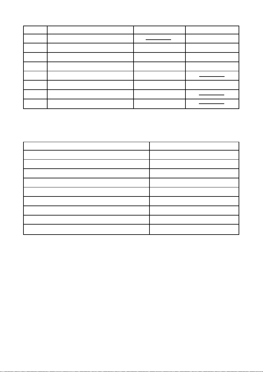
Table 3-1 Header 1 (First Byte)
Bit Content Status 0 Status 1
0 Always 1
1
2 Printer Status Byte Count
3
4 Always 0
5 Printer Status Byte Count
6 Reserved (Fixed at 0)
7 Not Used (Fixed at 0)
Table 3-2 Relationship of Actual Transmitted Byte Count and Header 1
Transmitted Byte Count n (7 n 15) Header 1
7 00001111B (0F Hex)
8 00100001B (21 Hex)
9 00100011B (23 Hex)
10 00100101B (25 Hex)
1 1 00100111B (27 Hex)
12 00101001B (29 Hex)
13 00101011B (2B Hex)
14 00101101B (2D He x)
15 00101111B (2F Hex)
Header 2
Header 2 is the information of the length of one byte transmitted in the second
byte of the automatic status. Table 3-3 shows the composition of the Header
2. Header 2 shows the version of the automatic status with bits 1 to 3 and bit
5 (called automatic status version below). For reference, Table 3-3 shows the
relationship between the actual version and the Header 2.
The automatic status version will be upgraded when new information is added
to the currently empty printer status bit positions through the addition of new
functions in the future. When the host does not manage the automatic status
version, it is acceptable that Header 2 be ignored.
52
Page 55
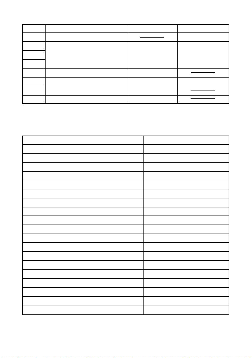
Table 3-3 Header 2 (Second Byte)
Bit Content Status 0 Status 1
0 Always 0
1
2 Automatic Status Ver. Number
3
4 Always 0
5
Automatic Status Ver. Number
6
7 Not Used (Fixed at 0)
Table 3-4 Relationship of Actual Automatic Status Version and Header 2
Version Number n Header 2
1 00000010B (02 Hex)
2 00000100B (04 Hex)
3 00000110B (06 Hex)
4 00001000B (08 Hex)
5 00001010B (0A Hex)
6 00001100B (0C Hex)
7 00001110B (0E Hex)
8 00100000B (20 Hex)
9 00100010B (22 Hex)
10 00100100B (24 Hex)
••
••
••
16 01000000B (40 Hex)
••
••
••
30 01101100B (6C Hex)
31 01101110B (6E Hex)
53
Page 56
Printer Status
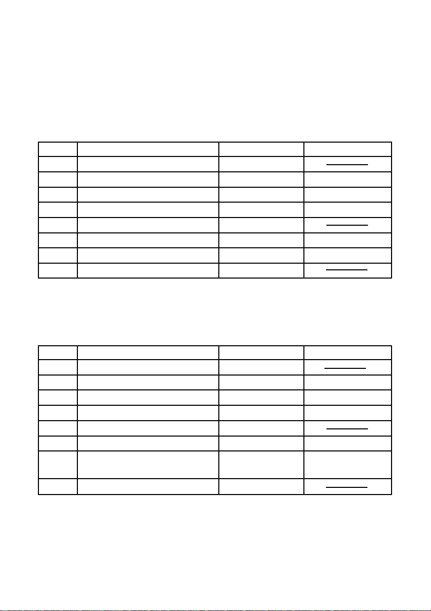
Printer Status is the overall status transmitted in the third byte of the automatic status. Printer status is returned as transmission byte count -2 added
by the Header 1. It always updates with new information. (There is no
historical record existing.) Tables 3-5 to 3-9 show the composition of the
overall status. The status of bits described as “Invalid” in the tables are
always “unknown.”
Table 3-5 Printer Status 1 <Printer Status> (Third Byte)
Bit Content Status 0 Status 1
0 Always 0
1 <ETB> Command Not Executed Executed
2 Compulsion SW Status Open Closed
3 Online/Offline Status Online Offline
4 Always 0
5 Invalid
6 Offline using the Online SW Does not occur Occurs
7 Not Used (Fixed at 0)
* Bit 1 is cleared to 0 when returned to the host. (Clearing bit 1 to 0 is not a
target for the automatic status.)
Table 3-6 Printer Status 2 (Error Information) (Fourth Byte)
Bit Content Status 0 Status 1
0 Always 0
1 Invalid
2 Mechanical Error No Error Error Occurred
3 Auto Cutter Error No Error Error Occurred
4 Always 0
5 Reset Not Possible Error No Error Error Occurred
6 Stopped Because of
Hot Print Head
7 Not Used (Fixed at 0)
Not Stopped Stopped
54
Page 57
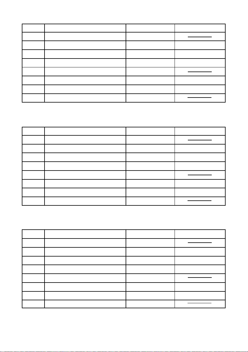
Table 3-7 Printer Status 3 <Error Information> (Fifth Byte)
Bit Content Status 0 Status 1
0 Always 0
1 Invalid
2 Invalid
3 Invalid
4 Always 0
5 Invalid
6 Reception Buffer Overflow Error (*) Does not occur Occurs
7 Not Used (Fixed at 0)
* Bit 6 is cleared to 0 when returned to the host.
Table 3-8 Printer Status 4 <Sensor Information> (Sixth Byte)
Bit Content Status 0 Status 1
0 Always 0
1 Invalid
2 Receipt Paper Near End Has Paper No Paper
3 Receipt Paper End Has Paper No Paper
4 Always 0
5 Invalid
6 Invalid
7 Not Used (Fixed at 0)
Table 3-9 Printer Status 5 <Sensor Information> (Seventh Byte)
Bit Content Status 0 Status 1
0 Always 0
1 Invalid
2 Invalid
3 Invalid
4 Always 0
5 Invalid
6 Invalid
7 Not Used (Fixed at 0)
55
Page 58
(2)Precautions
Do not use the <ENQ>, <EOT>, <ESC>, <ACK> or <SOH> commands when
the automatic status is valid. You must first invalidate the use of the automatic
status function using the DIP switches or the <ESC> <RS> “a” n command to
use these inquiry commands.
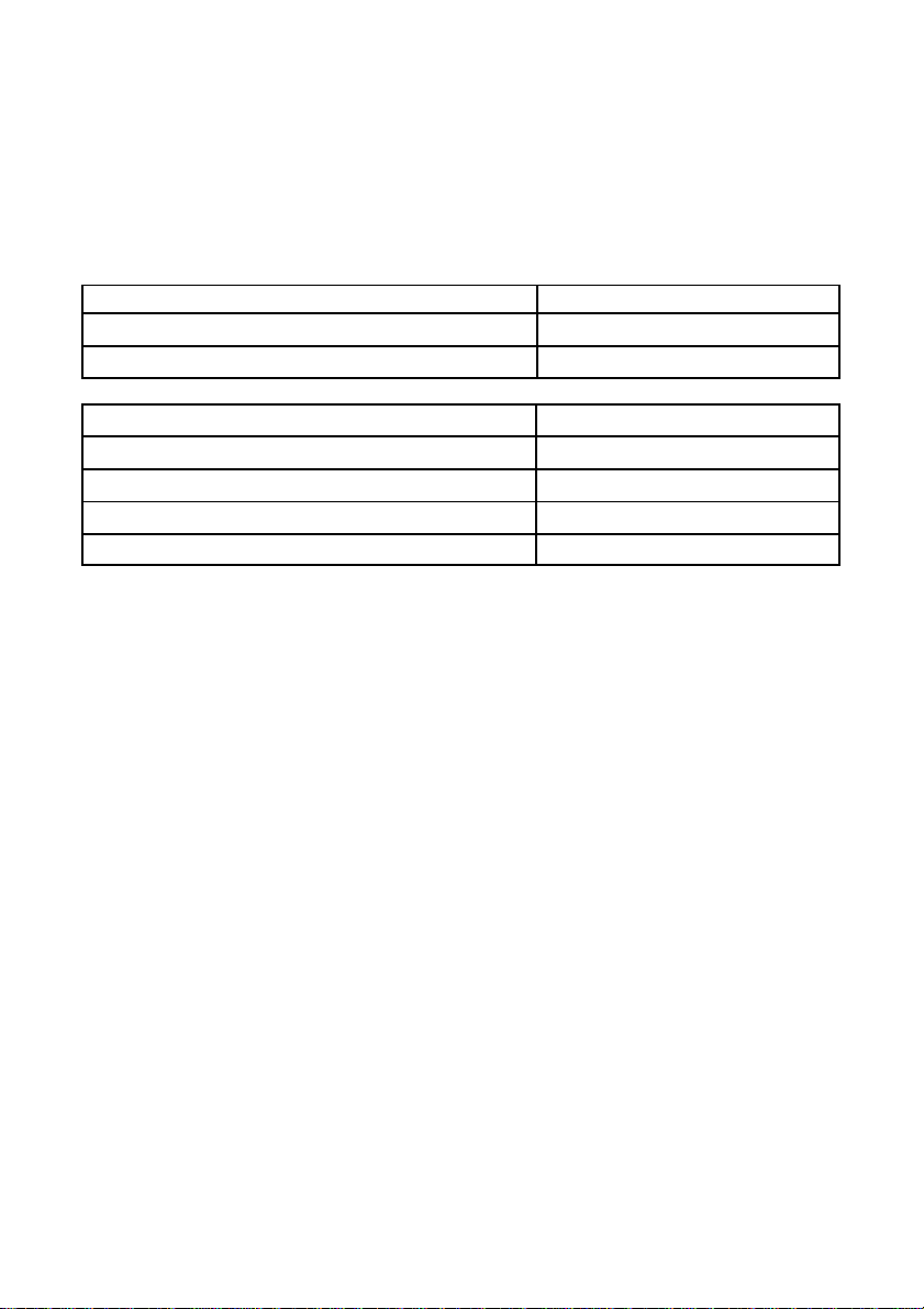
(3)Method to Identify States
<Control Code> <Reception Data>
XON <00010001>B
XOFF <00010011>B
<Status> <Reception Data>
ENQ Status <***0****>B
EOT Status <***1***0>B
Automatic Status (First Byte <Header 1>) <0**0***1>B
Automatic Status (Second Byte and Beyond) <0**0***0>B
0 = indicates bit fixed to 0.
1 = indicates bit fixed to 1.
* = indicates bit changed.
56
Page 59
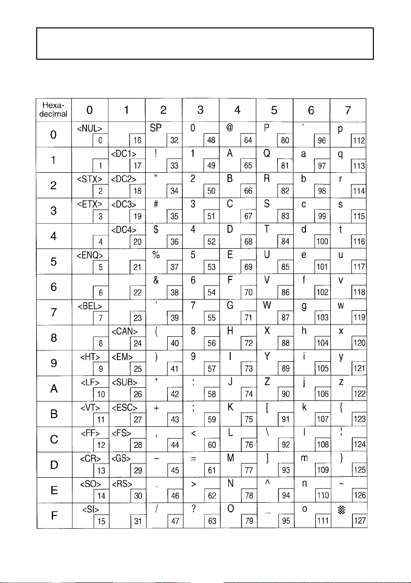
Appendix : Character Code Tables
Star Mode
(Character table: Normal)
Note: The (7F)H code is a space when neither normal nor katakana.
57
Page 60
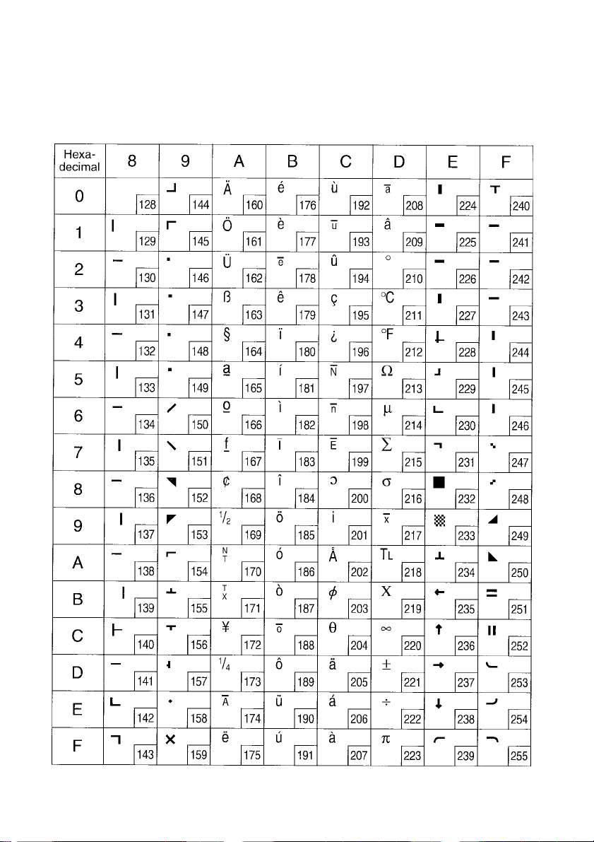
Star Mode
(Character table: Normal)
58
Page 61
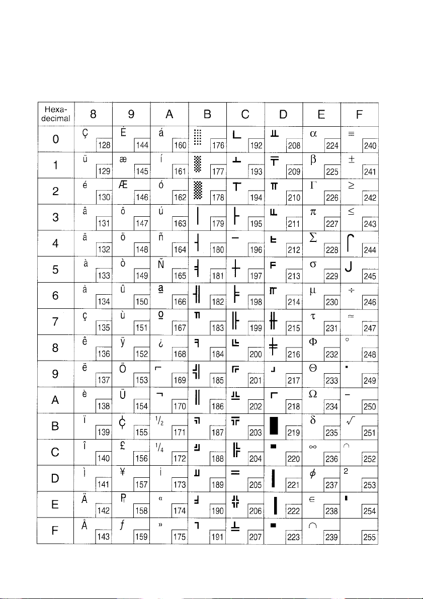
Star Mode
(Character table: IBM Character set #2 (Code page 437 ))
Note: Other characters are the same as those for Character table: Normal.
59
Page 62
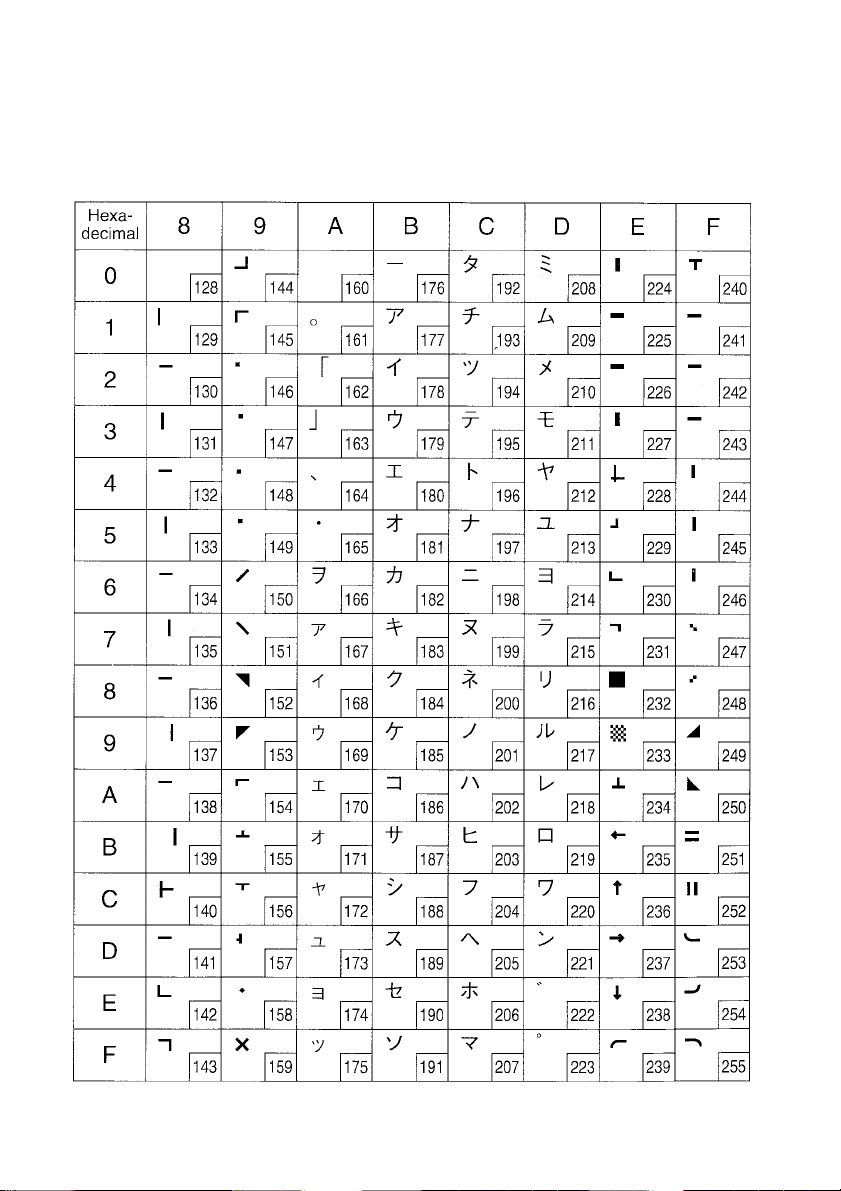
Star Mode
(Character table: Katakana)
Note: Other characters are the same as those for Character table: Normal.
60
Page 63
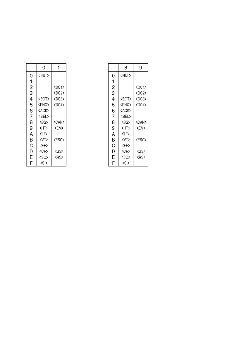
Star Mode
(Character table: IBM Character set #1 )
Note: Other characters are the same as those for IBM Character Set #2.
61
Page 64
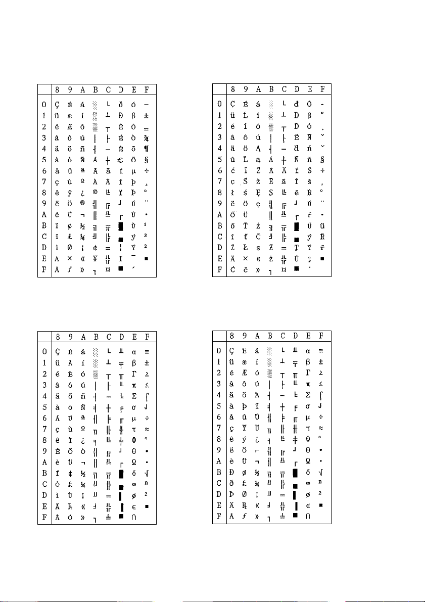
Star Mode
Code Page #858 Code Page #852
Multi-lingual Latin-2
Code Page #860 Code Page #861
Portuguese Icelandic
Note: Other characters are the same as those for Character table: Normal.
62
Page 65
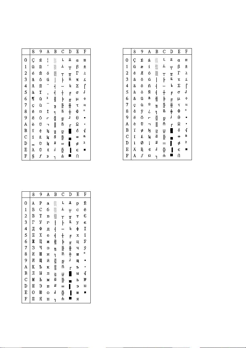
Star Mode
Code Page #863 Code Page #865
Canadian French Nordic
Code Page #866
Cyrillic Russian
Note: Other characters are the same as those for Character table: Normal.
63
Page 66
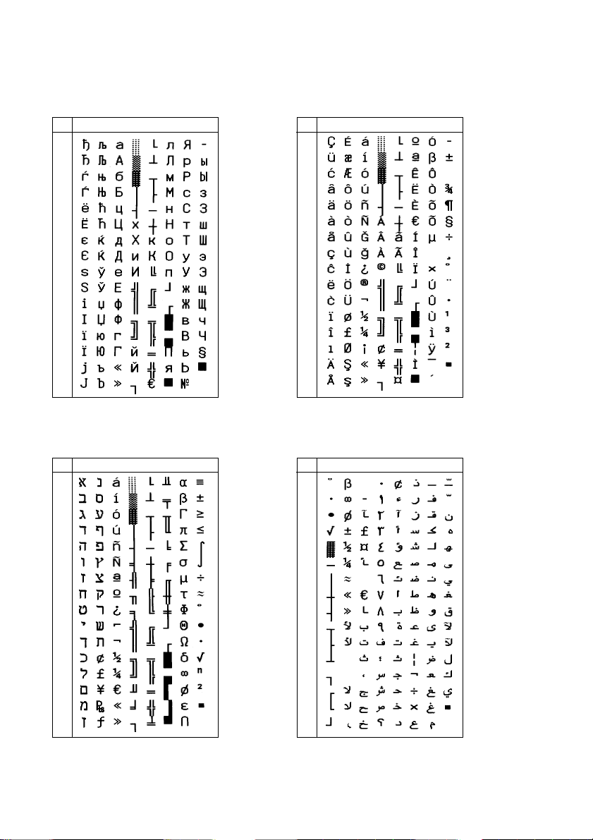
Star Mode
Code Page #855 Code Page #857
Cyrillic Bulgarian Turkish
8 9 A B C D E F
0
1
2
3
4
5
6
7
8
9
A
B
C
D
E
F
Code Page #862 Code Page #864
Hebrew Arabic
8 9 A B C D E F
0
1
2
3
4
5
6
7
8
9
A
B
C
D
E
F
8 9 A B C D E F
0
1
2
3
4
5
6
7
8
9
A
B
C
D
E
F
8 9 A B C D E F
0
1
2
3
4
5
6
7
8
9
A
B
C
D
E
F
Note: Other characters are the same as those for Character table: Normal.
64
Page 67
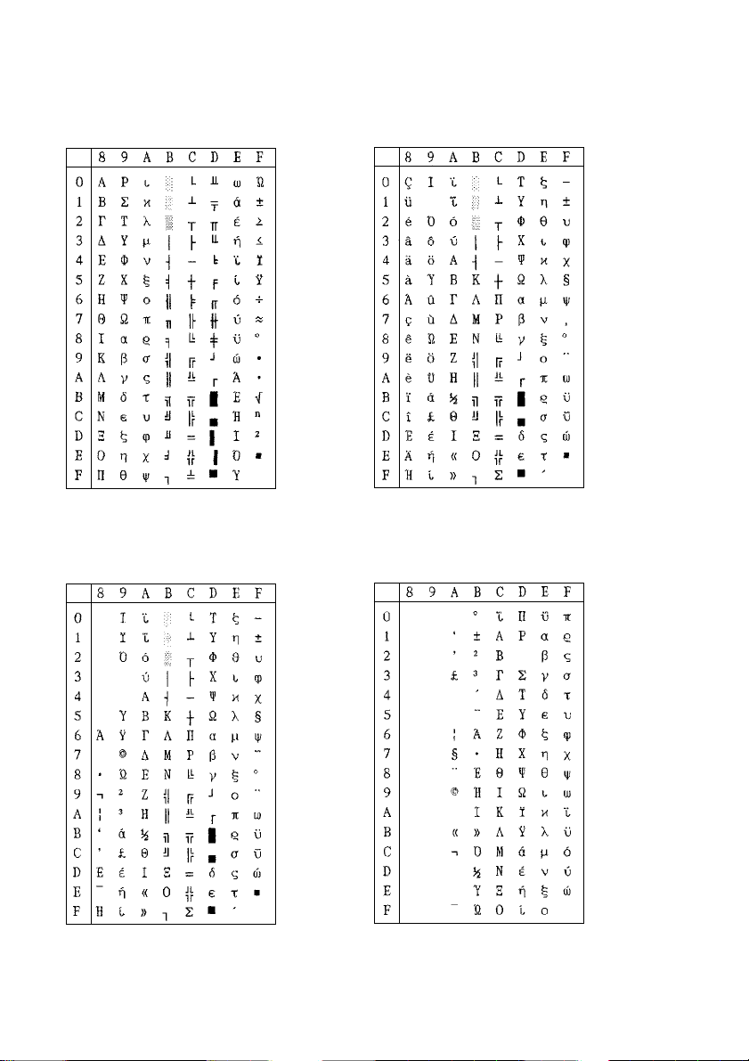
Star Mode
Code Page #737 Code Page #851
Greek Greek
Code Page #869 Code Page #928
Greek Greek
Note: Other characters are the same as those for Character table: Normal.
65
Page 68
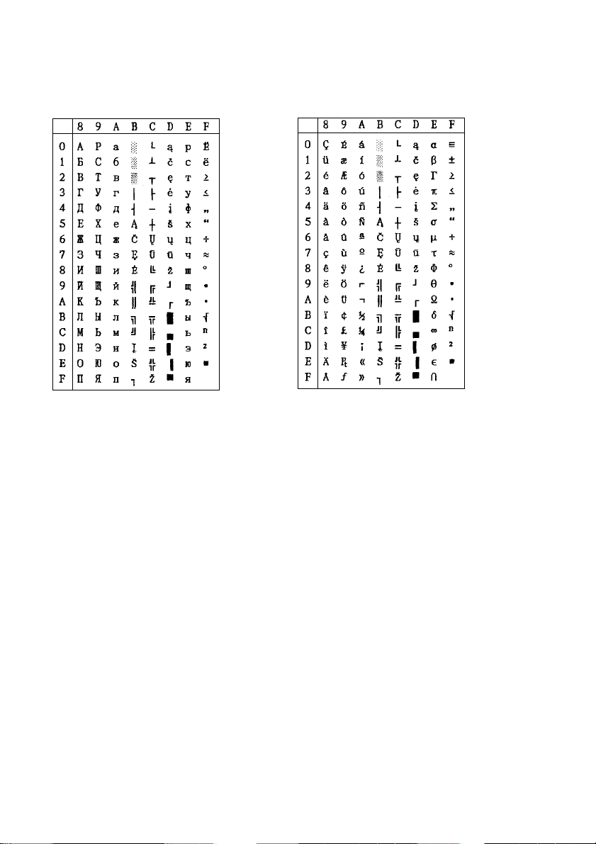
Star Mode
Code Page #772 Code Page #774
Lithuanian Lithuanian
Note: Other characters are the same as those for Character table: Normal.
66
Page 69
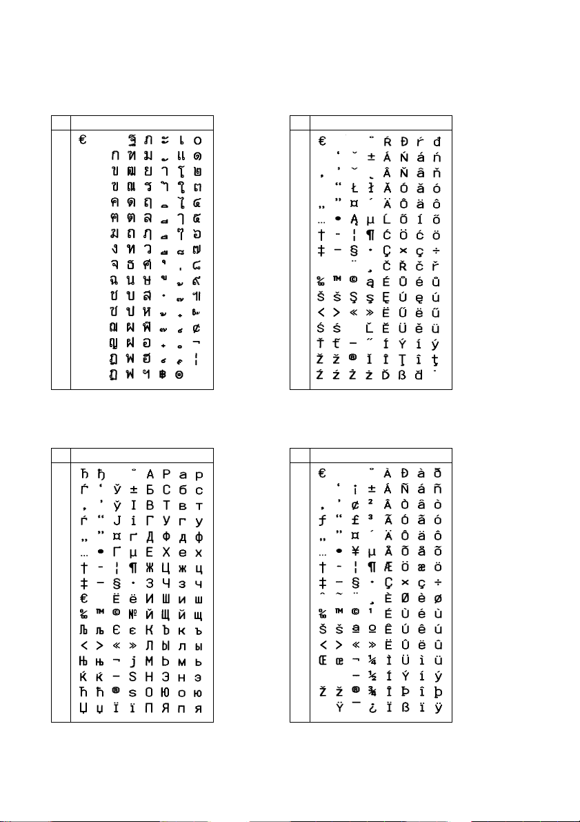
Star Mode
Code Page #874 Code Page #1250
Thai Windows Latin-2
8 9 A B C D E F
0
1
2
3
4
5
6
7
8
9
A
B
C
D
E
F
Code Page #1251 Code Page #1252
Windows Cyrillic Windows Latin-1
8 9 A B C D E F
0
1
2
3
4
5
6
7
8
9
A
B
C
D
E
F
8 9 A B C D E F
0
1
2
3
4
5
6
7
8
9
A
B
C
D
E
F
8 9 A B C D E F
0
1
2
3
4
5
6
7
8
9
A
B
C
D
E
F
Note: Other characters are the same as those for Character table: Normal.
67
Page 70
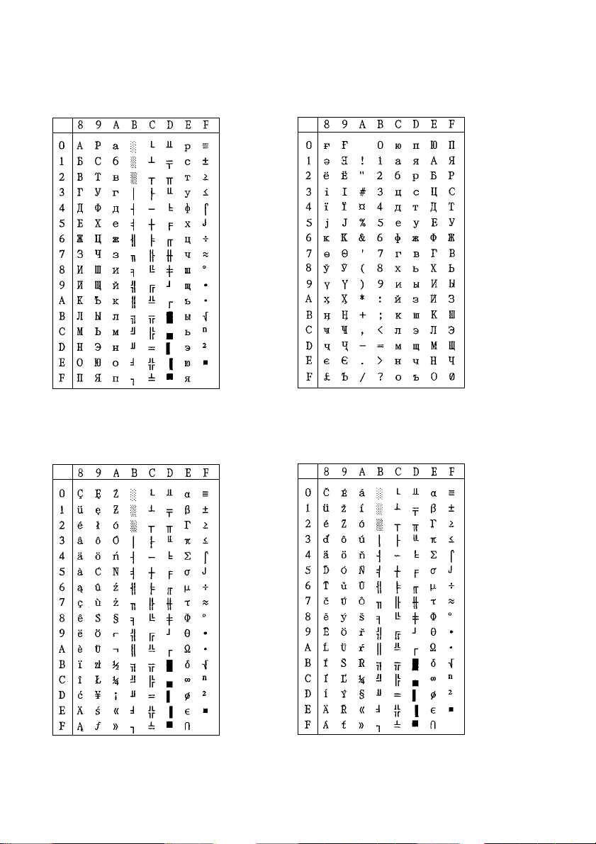
Star Mode
Code Page #3840 Code Page #3841
IBM-Russian Gost
Code Page #3843 Code Page #3844
Polish CS2
Note: Other characters are the same as those for Character table: Normal.
68
Page 71
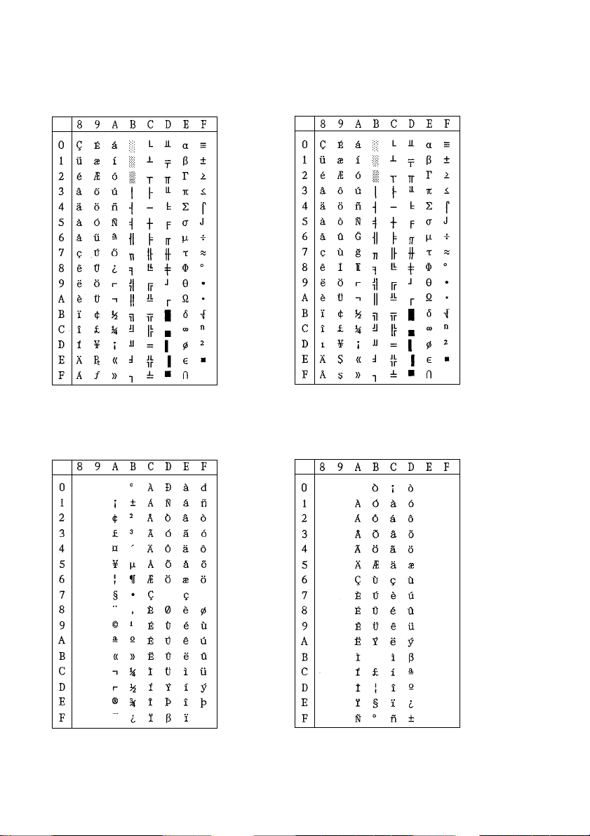
Star Mode
Code Page #3845 Code Page #3846
Hungarian Turkish
Code Page #3847 Code Page #3848
Brazil-ABNT Brazil-ABICOMP
Note: Other characters are the same as those for Character table: Normal.
69
Page 72
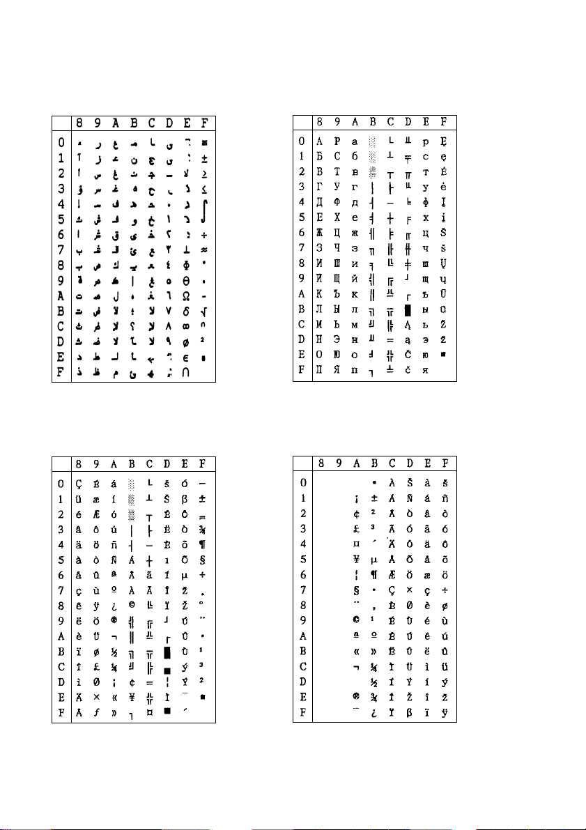
Star Mode
Code Page #1001 Code Page #2001
Arabic Lithuanian-KBL
Code Page #3001 Code Page #3002
Estonian-1 Estonian-2
Note: Other characters are the same as those for Character table: Normal.
70
Page 73
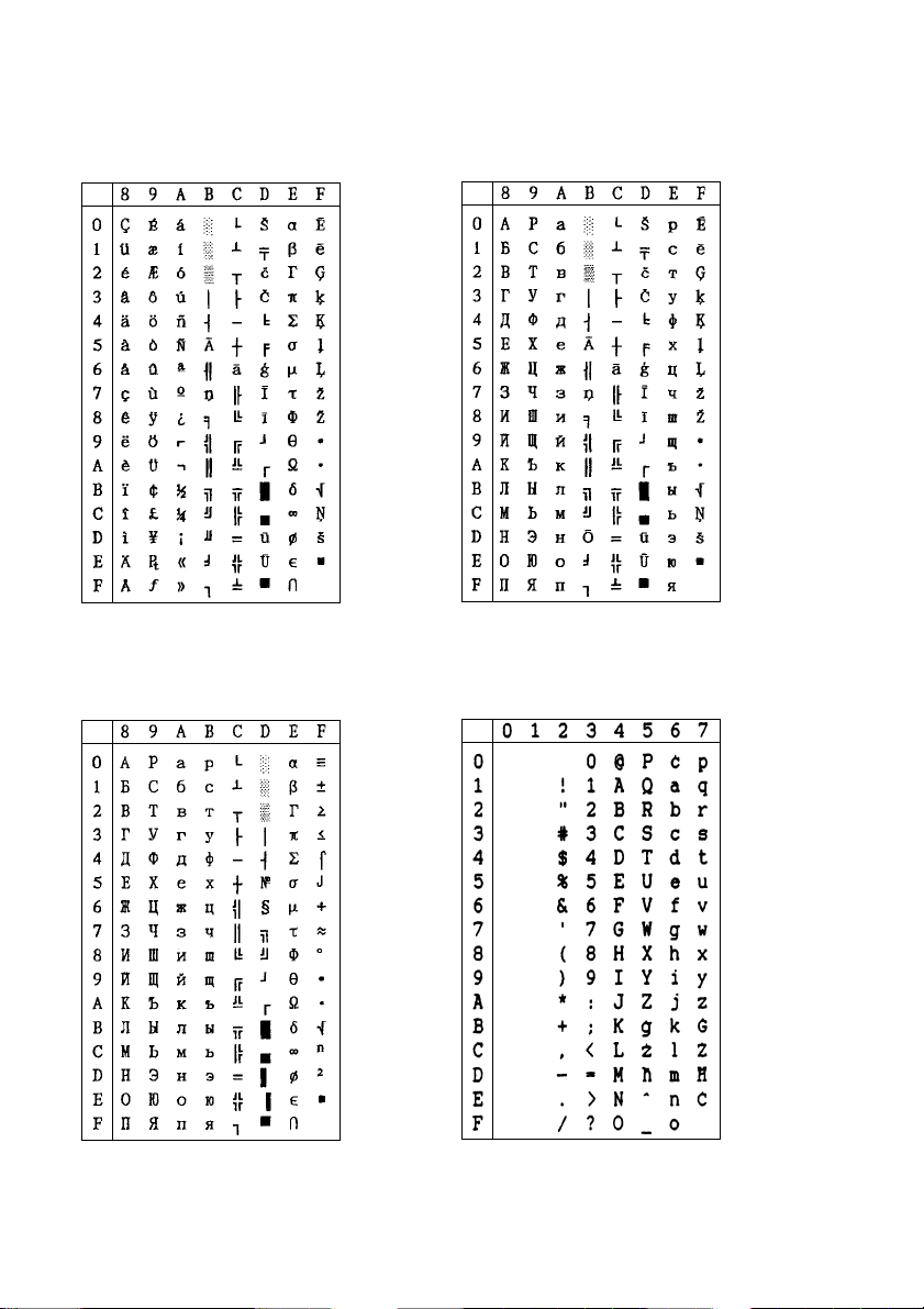
Star Mode
Code Page #3011 Code Page #3012
Latvian-1 Latvian-2
Note: Other characters are the same as those for Character table: Normal.
Code Page #3021 Code Page #3041
Bulgarian Maltese
Note: Other characters are the
same as those for Character table: Normal.
Note: Other characters are the
same as those for Code
Page #437.
71
Page 74
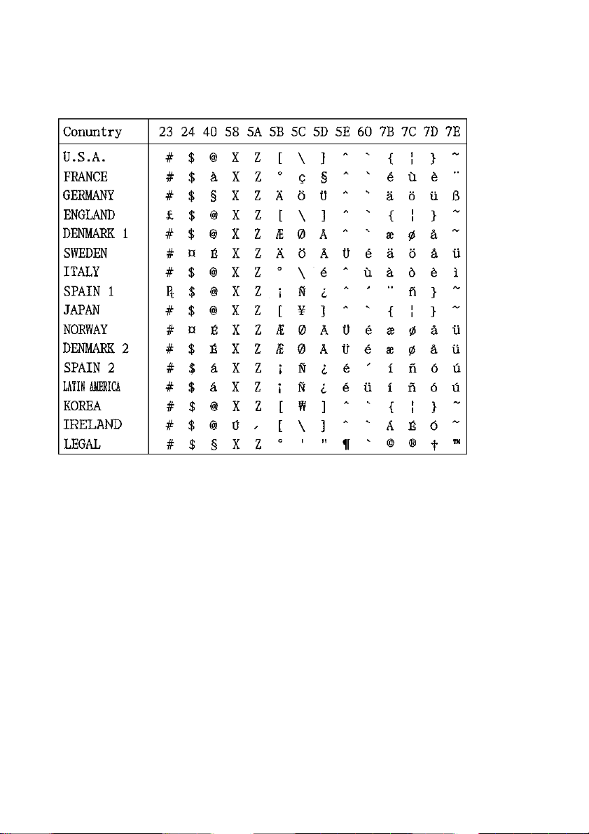
Star Mode
International Character Set
The character codes shown in the table are hexadecimal.
72
Page 75
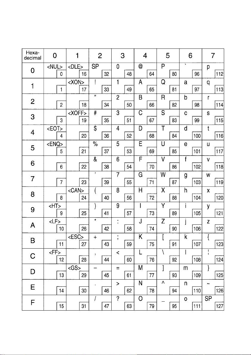
ESC/POS Mode
Page 0 (PC437)
73
Page 76
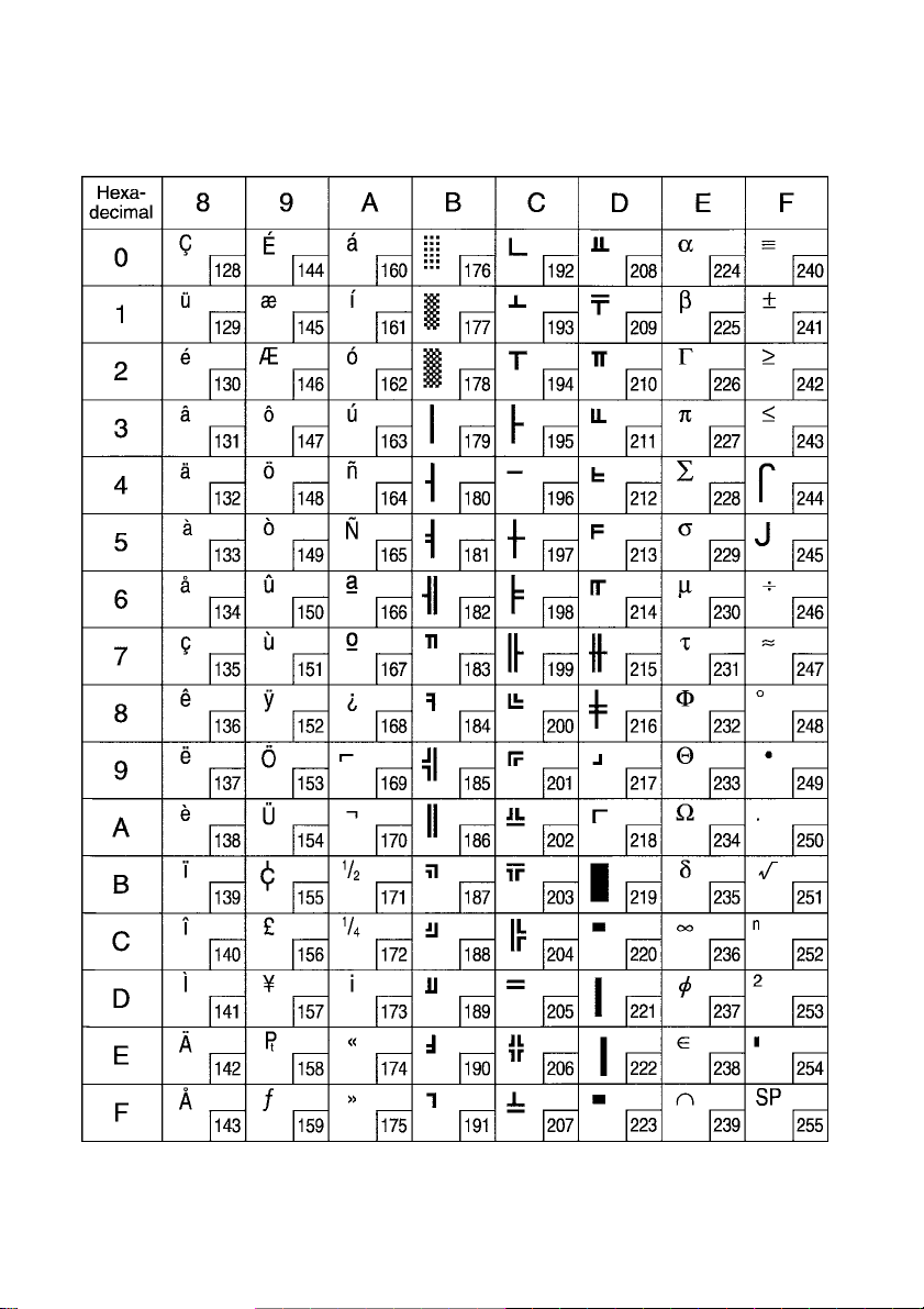
ESC/POS Mode
Page 0 (PC437)
74
Page 77
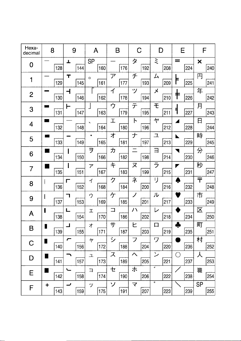
ESC/POS Mode
Page 1 (Katakana)
Note: Other characters are the same as those for Page 0.
75
Page 78
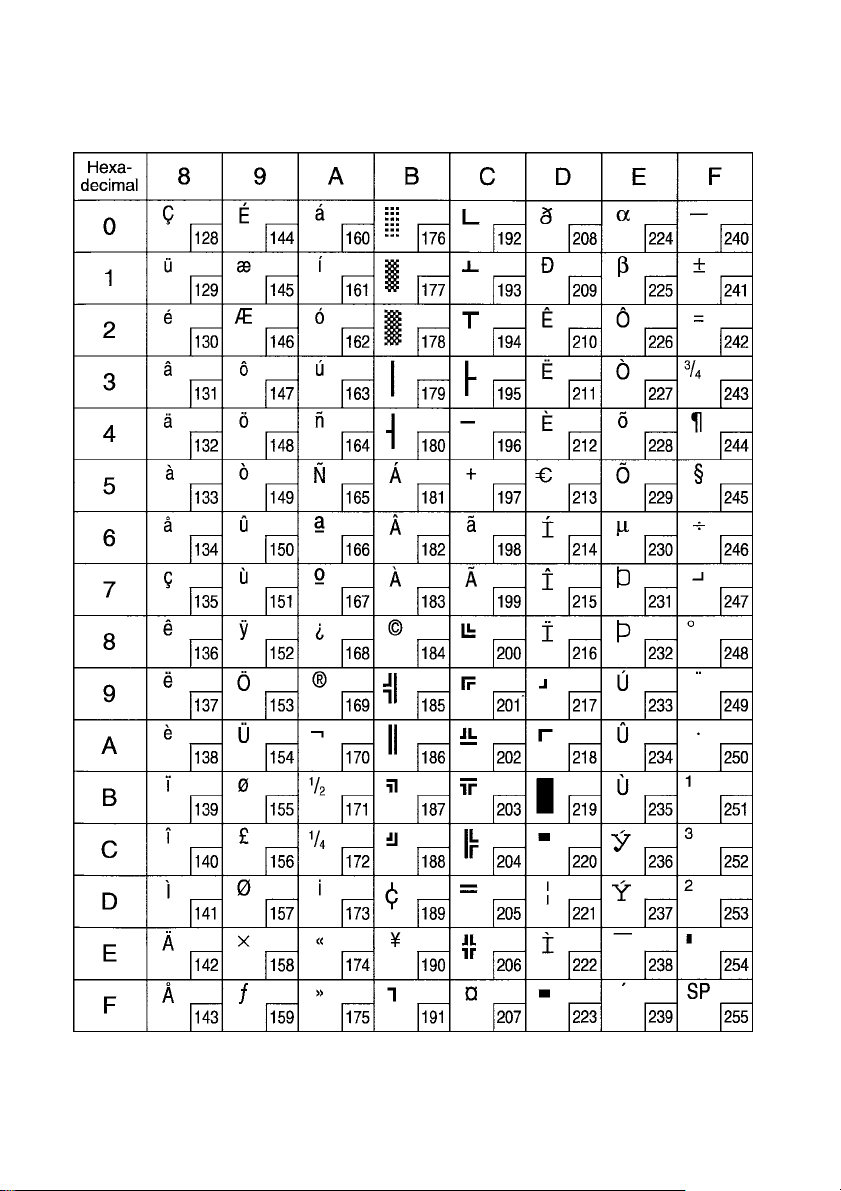
ESC/POS Mode
Page 2 (PC858: Multilingual)
Note: Other characters are the same as those for Page 0.
76
Page 79
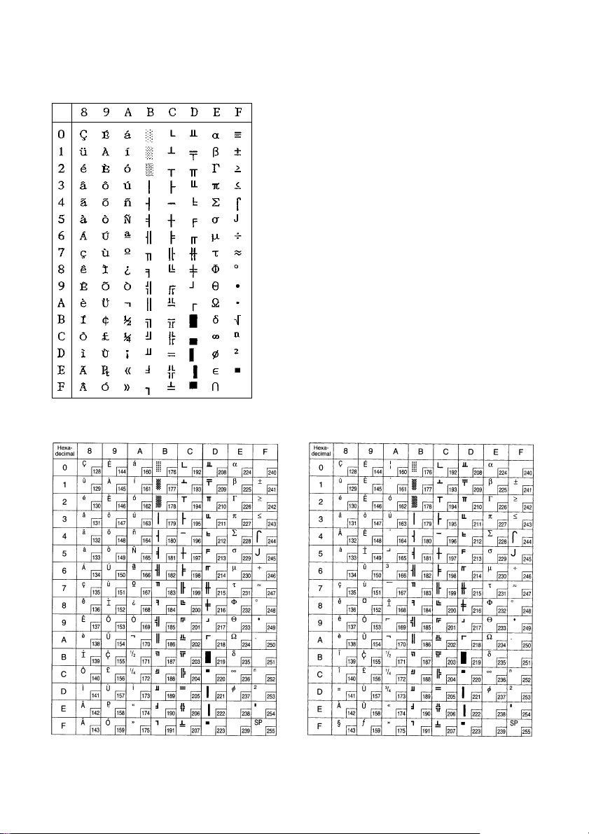
ESC/POS Mode
Page 3 (PC860: Portuguese)
Page 4 (PC863: Canadian-French) Page 5 (PC865: Nordic)
Note: Other characters are the same as those for Page 0.
77
Page 80
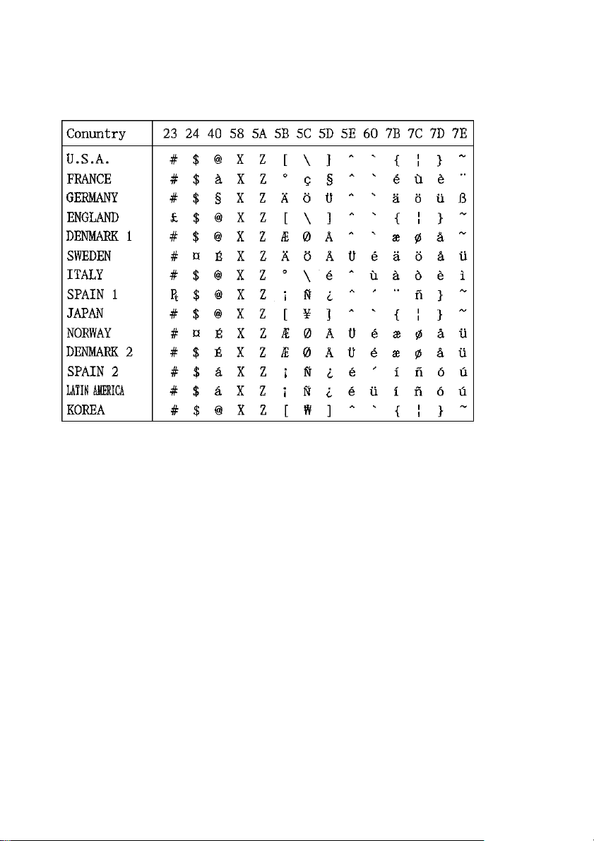
ESC/POS Mode
International Character Set
The character codes shown in the table are hexadecimal.
78
Page 81

ELECTRONIC PRODUCTS DIVISION
STAR MICRONICS CO., LTD.
536 Shimizunanatsusinnya, Shizuoka,
424-0066 Japan
Tel: 0543-47-0112, Fax: 0543-48-5013
OVERSEAS SUBSIDIARY COMPANIES
STAR MICRONICS AMERICA, INC.
1150 King Georges Post Road, Edison,
NJ 08837-3729 U.S.A.
Tel: 732-623-5555, Fax: 732-623-5590
http://www.starmicronics.com
Please access the following URL
http://www.star-micronics.co.jp/service/frame_sp_spr_e.htm
for the lastest revision of the manual.
STAR MICRONICS EUROPE LTD.
Star House, Peregrine Business Park, Gomm Road,
High Wycombe, Bucks, HP13 7DL, U.K.
Tel: 01494-471111, Fax: 01494-473333
http://www.StarMicronicsEurope.com
2003.08.31
Printed in Japan, 80872080
 Loading...