

Page 1
ROTATING AND REPLACING THE OS2
ROTATING INSTRUCTIONS
1 . Remove the face plate.
2. Remove the 2 outer screws from the
round OS2 plate (removing the 2 inner
screws will detach the fader from the
plate)
3. Rotate the plate to the desired position and tighten the screws back into
the top and bottom holes.
WARRANTY
This unit has been designed and man ufactured using quality components.
Therefore, it is warranted to be free
from defects in materials (limited as
specified below), and workmanship for
a period of twelve (12) months from the
original purchase date. During this
period, all service and parts necessary
to repair a defect will be free of charge.
This limited warranty applies to
mechanical parts which are subject to
wear and tear as specified: Faders,
specified durability: 15,000 cycles;
Rotary potentiometers, specified dura bility: 10,000 cycles; Switches, speci fied durability: 10,000 cycles.
REPLACING INSTRUCTIONS
1. Remove the the face plate.
2. Remove the 2 outer screws from the
round plate (removing the 2 inner
screws will detach the fader from the
plate)
3. Remove the OS2 assembly and disconnect the cable coming from the
mixer.
4. Set the replacement fader assembly
in the desired position and place the
screws back in the top and bottom
holes.
Consequently, the parts listed above
are warranted to be free from defects in
materials and workmanship for a period of thirty days (30) days from the
original purchase date.
For the warranty to be valid, please
complete the warranty registration card
attached or fill out the online registra tion
at www.stantonmagnetics.com
Mail completed warranty cards to:
Stanton Magnetics, Inc, 3000 SW 42st
• Hollywood, FL 33312
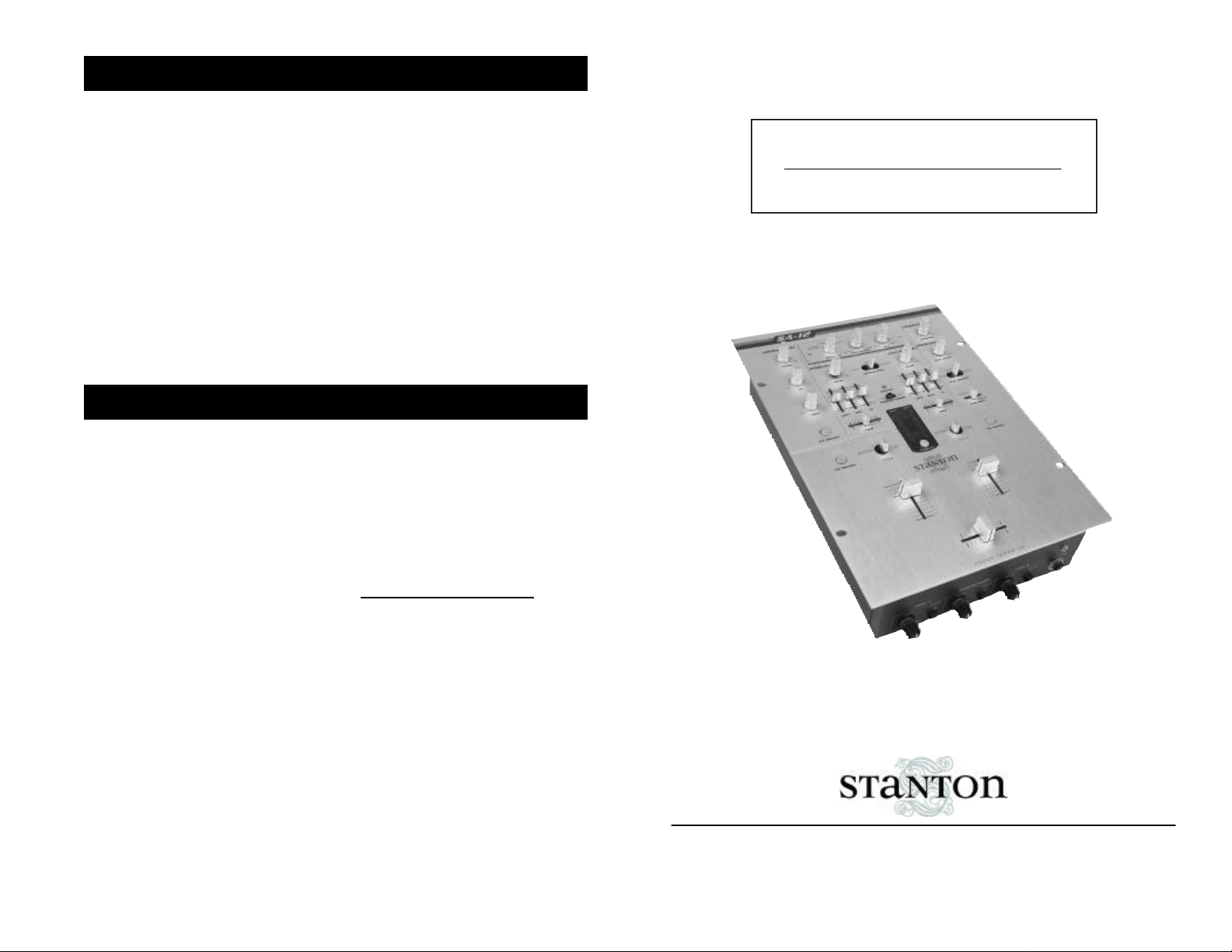
SA-12
DJ CRAZE SIGNATURE MIXER
© 2001, Stanton Magnetics, LLC
OWNER’S MANUAL
STANTON MAGNETICS, INC
info@stantonmagnetics.com • (954) 689-8833
www.stantonmagnetics.com
Page 2
TECHNICAL SPECIFICATIONS
Thank you for making Stanton your first choice in professional DJ mixers.
This innovative family of mixers has been developed with input from the
professional DJ community, bringing to the marketplace a previously
unavailable, affordable combination of user-friendly, functional design,
rugged construction, and professional quality features.
Stanton and your authorized Stanton dealer are dedicated to your complete
satisfaction by offering benchmark service and support throughout the long
life of your Stanton product.
Again, we appreciate your patronage, and look forward to many years of
making music together.
PLEASE READ CAREFULLY BEFORE USE
FAILURE TO FOLLOW THE INSTRUCTIONS PRINTED BELOW MAY VOID WARRANTY
• Follow all security advice printed on your mixer
• When removing the unit's AC plug from the power source, grasp and pull
the plug, NEVER the cord itself!
• Avoid placing your mixer near heat sources, such as power amplifiers.
• When in use, place your mixer on a stable surface, away from vibration.
Always use care when carrying your mixer. Impact, or heavy vibration may
compromise the unit's mechanical integrity. The manufacturer is not
responsible for damage resulting from an impact, or misuse.
• When in use, place your mixer away from sources of hum or noise, such as
transformers, or electric motors.
• To prevent overheating, always provide your mixer with adequate
ventilation air space.
• Avoid stepping on your mixer's AC cord. Repeated compression of the cord
may lead to electrical shorting.
Line inputs: 2 (RCA),
Phono inputs: 2 (RCA),
DJ mic input: 1 (1/4 inch), 2.45 mV / 3K ohm
Master output: 2 (1/4” TRS Balanced/RCA unbalanced),
-10dBV @ <10Kohm
-50dBV @ <10Kohm
Balanced 4dBu into 10Kohm
Unbalanced: -10dBV into 10Kohm;
Headphone output: 1 (1/4 inch), 1 Minijack (1/8 inch) 32 - 200 ohms
recommended
Frequency Response: 20 Hz - 20 kHz, +0 dB
Tone Control : + 9 / Kill dB (Hi, Mid, Low)
Mic Tone: Hi/Lo +/-10 dB
Dynamic Range: line 90dB, phono 85dB
S/N Ratio:
Phono EIN:
Dimension (LxWxD):
75dB
105 dB
14.9" x 10.5" x 4.3"
379mm x 266.5mm x 109mm
Weight: 8 lbs (3.6 Kg)
REPLACEMENT PARTS
To replace the cross or channel faders, follow steps 1 and 2 of the
cleaning instructions. The following replacement parts are available
from Stanton or your local Stanton dealer.
LF-SK2
CF-PG110
CF-F2
OS2
SHP0531 (top) SHP0532 (btm)
Channel input fader
Penny & Giles
Focus Fader V2
Optical Scratch switch
phono/line selector
PS-SA12US
PS-SA12EU
PS-SA12UK
PROTEKT™ panel
US Power
Supply (110v)
European Power
Supply (220v)
UK only Power
Supply (240v)
• To avoid damage due to AC voltage peaks, always disconnect your mixer
from the power source during electrical storms. If possible connect mixer to
a surge protector.
• Your mixer contains no user-serviceable parts. The manufacturer is not
responsible for any damage or personal injury resulting from unauthorized
user-servicing or modifications. In addition, the warranty will be void if any
unauthorized service by the user is detected. Always return your mixer to
an authorized Stanton dealer for servicing.
Page 3

FADER CLEANING AND REPLACEMENT
SA-12 FUNCTIONS & FEATURES
remove the slider assembly (C), ensuring that the wiper contacts (D) are
not damaged as this will affect the operation of the fader. Clean the slid er assembly by gently wiping the wiper contacts and slider bearings (E)
using a tissue or cotton bud. If slider bearing are exessively worn, as indicated by exessive slider rocking then contact Stanton for replacement.
3.
Remove the single upper screw on the
opposite end block to remove the guide rail.
Clean the guide rail (F) with a tissue or
cloth, removing all traces of dirt and contamination.
4.
Remove the fader track (G) by slowly with -
drawing from the unit. Place fader track on
desk or working surface with black contacts facing upwards.
If necessary, the track can be washed in warm water, wiped
gently then dried thoroughly using a dry cloth. Use a lint free
cloth or swab to wipe the tracks and check for marks along
the track. (Note: Lint free cloth should be used to avoid
dust/fibres being deposited on the track). If the track appears
exessively worn, or if cleaning does not improve operation,
replacement may be necessary.
5.
Examine the center channel of the fader body and if dirty, clean using cot-
ton buds.
6.
Re-assemble and lubricate the fader as follows:
6.1
) Secure the end block and guide rail onto the fader body.
6.2
) Insert track into the fader body.
6.3
) Insert slider assembly onto guide rail and into the fader body. Move
slider from end to end to disperse the oil evenly. Carefully wipe away any
excess oil using a tissue or cloth.
6.4
) Lubricate the guide rail by placing one drop of silicon liquid oil onto
the guide rail (F).
6.5
) Insert dust cover.
6.6
) Insert fader track back into fader body with wires coming out open
end of fader body.
6.7
) Secure the remaining end block ensuring that the track wires (I) are
not pinched between the endblock and fader casing.
7.
Once assembled, move the slider from end to end to ensure operation is
smooth.
8.
Attach fader to fader plate. (NOTE: As noted earlier if you do not want to
change positioning of fader, keep the 2 fader plate screws loose and shift
the fader until it is aligned with the marks you created in step 1, then tighten fader plate screws.)
G
It’s only the 3x champion, DJ Craze signature mixer! This battle mixer has the all
the quality of a club mixer and meets all the requirements of today's Turntablist.
After years in the making the ultimate Scratch DJ mixer is here and ready for battle.
Removable Effects Module
The MOD1 removable effects module
includes 3 effects: Pitch Shifter,
Flanger, and Delay. All effects have
adjustable parameters and levels, can
be assigned (turned on / off) to all
channels or master output, and can be
turned ON/OFF using any standard
footswitch via the remote Start output.
I
OS2 Optical Scratch Switch
These ultra quiet, non friction
phono/line switches allow you to transform without the clicking or static noise
found in other line switches. Now
including a special feature that locks
the last position of the switch.
3 position Cue Select
This switch allows you to set your cue
source to PFL/Pre -crossfader,
PFL/Post-crossfader, or Master. This
unique PFL/Post-crossfader features
allows you to practice and cue your
scratches using the crossfader
(instead of the cue pan fader) during a
live show.
Mic/Line Channel
The SA-12’s Mic/Line channel features
an input selector switch activating a 3rd
line input (RCA) or a standard microphone input, both controlled by a 2band EQ with gain adjustment. This
can also be used as a "session in" with
volume control for linking additional
mixers.
FEATURES:
• Focus Fader V2 Digital Optical
Crossfader
(Patent Pending)
with
curve adjustment and reverse switch.
• OS2
(Patent Pending)
Optical Scratch
switches with lock feature
• Removable effects module
Pending)
. SA-12 includes MOD1:
(Patent
Pitch Shifter, Flanger, and Delay; with
Parameter and Mix controls.
• Effects fully assignable
• Foot pedal output to control effects.
• 3 position cue select
(Patent Pending)
Pre CF Cue / Post CF Cue / Master.
• 2 line, 2 phono, and 1 mic/line (switch-
• 3 band EQ with complete kill, Gain,
and Pan control per channel.
• Program Faders reverse switches &
curve adjustments.
• Headphone mute.
• Cue Pan Fader
• Dual headphone inputs (1/4 and 1/8
mini-jack).
• TRS balanced Master output.
• Mono-Stereo Switch.
• Output Trim control.
• Quiet-Start feature to avoid pops /
noise when mixer is powered on.
able) inputs.
• Program Reverse.
Page 4

DESCRIPTION OF FUNCTIONS
FADER CLEANING AND REPLACEMENT
After constant scratch use the SA-12 faders may need to be cleaned and lubricated from time to time. This will ensure long life and keep a smooth feeling
throughout the fader's lifetime. Follow the instructions below to lubricate and
clean your faders:
PostScript Picture
SA-12_callouts.eps
Removing a fader
1.
Make sure mixer is powered off and power supply is
:
disconnected from back of mixer.
2
. To remove the lower faceplate, take off the 3 fader
knobs and then remove the 4 screws located on
the sides of the mixer (2 on each side). See Figure
1. Lift up on the faceplate and it will slide off.
3.
Remove the fader to be cleaned or replaced by
unscrewing the 2 outer screws on the fader plate
(removing the 2 inner screws will detach the fader
from the fader plate). See Figure 2.
4.
Disconnect the fader from mixer by removing the 4-
pin connector on the bottom of the fader.
Replacing a fader
1.
Once original fader has been removed, simply plug
:
the 4-pin connector into the new fader. NOTE: The
SA-12 comes with 2 connectors, one for P+G
faders and one for Focus Faders. Make sure you
plug in the correct fader with the correct connector.
See Figure 3.
2.
Set selector switch to position of fader you are using
(P+G or Focus Fader). See Figure 3.
3.
Place fader back in mixer and replace 2 outer
screws to secure fader.
Cleaning a Penny & Giles fader
:
Figure 3
1.
Remove 2 mounting scews from faderplate. (NOTE:
The P&G fader is designed with floating mounting
threads for precise mechanical centralising of the
fader. If you desire to keep your fader`s current
mounting position we suggest that you make 2
marks on both ends of the fader on the fader plate
to indicate the P&G fader position.) See Figure 4.
2.
Once fader is removed from unit,
remove the two screws (A) from
the end of the fader body where
the wires exit the fader casing. Pull
away the end block. Withdraw the
dust cover (B). Taking great care,
B
A
G
C
F
E
D
Page 5

FOCUS FADER V2
Improving on the original and world's first optical fader design that brought the
industry and art to a new plateau, the Focus Fader V2 is truly curve adjustable to
accommodate to any style of DJ artist. Created to meet the requirements of
today’s higher standards , if your style requires a smooth fade for long mixes or a
razor sharp cut-off for precise scratching, V2 is the answer.
Just as it's predecessor started a movement in contactless fader designs, the
Focus Fader V2 Digital Optical Fader will continue to push the envelope. No more
bleeding, no more static, no more wasted time, just hours of practice enjoyment
and flawless performance.
The Focus Fader V2 is highly advanced and opens many doors for innovations in
DJ equipment technology. Fitted with an array of optic sensors and microproces sor controlled to eliminate the need for contacts or graphite material. V2 is as pure
as the sun rays. It will outlast any standard graphite or conductive plastic fader on
the market. This is why the it has a limited lifetime warranty (see warranty infor -
mation section).
The Focus Fader V2 is history in the making.
OPTICAL SCRATCH SWITCH (OS2)
Since the early days of DJing and Scratching the Phono/Line Switch had been an
integral part of an artist’s performance. In recent years the new techniques in
scratching have evolved to a point that surpassed the typical contact switch which
is too noisy to use in a performance. This led to the decline of its use. In any art
form the goal should be to move forward, the slow decline of the phono/line switch
use was a step backwards. Introducing the OS2.
Just as the introduction of the Focus Fader V1 has changed the face of the DJ
world for the good of all, so will the OS2. The Benefits are the same as other opti cal devices, such as the Focus Fader.: 1. No more static, 2. No more bleeding, 3.
Lots of scratching fun.
One Step Further: In addition to the sound benefits the OS2 also represents a
Stanton innovation in it's mechanical properties as well. It is the 1st phono/line
switch which uses a fader as the user interface. This will allow the same
hand/wrist movement to be executed when using the crossfader and OS2 which
in turn translates into efficiency in Scratching performance.
The flat handle and soft slide action of the OS2 makes it easy to perform any existing techniques including the Crab Scratch. The small travel and slide motion will
be a positive tool in conditioning the hand/wrist movements to be more minute and
precise. In conclusion the OS2 is another step forward in the Evolution of the DJ
Culture and of course as always Scratching.
TOP PANEL
1. Mic/Line 3 level control
the output level of the microphone/
Line channel.
2. Gain
: Controls the gain of each input
channel.
3. Mic/ Line 3 EQ
for low and high frequency equaliza tion with (+/-10 dB)
4. EQ
: Individual controls for low fre quency, midrange, and high frequency
equalization with (+9dB/Kill) Note: Any
changes made to EQ settings will
change the overall output level.
5. FX ON/OFF
control the signal flow of the effects
module. Press any of the buttons sep arately to turn the effects on or off for
Ch1, Ch2, or Mic/ Line 3. The correc sponding button will light up to show
the effect is on. When turned on indi vidually, there can only be one channel
effected. Assigning the effect toi a dif ferent channel will turn off the effect on
the previous channel. When Ch1 and
Ch2 are pressed simultaneously, the
effect signal is sent to the master out put, and both (Ch1 & Ch2) buttons will
be lit. When connecting a foot pedal to
the remote output (31), the FX ON/OFF
buttons become assign switches and
the foot pedal becomes the actual
ON/OFF switch. The selected button
will flash to show it is selected, and it
will light up once the foot pedal is
pressed to show the effect has been
turned on.
6. Pan control
put balance of each channel.
7. Optical Scratch Switches (OS2)
Switches between the phono and line
inputs.
8. Headphone mute
headphones without having to change
its level.
: Individual controls
: These backlit buttons
: Controls left/right out -
: Controls
: Mutes the
9. Channel fader
nel output level.
10. Crossfader
mixer output between channels 1 and
2. See “Focus Fader V2” section for
more details.
11. Input Level Meter
channel’s input level with peak hold
function
12. Cue pan
output between channels 1 and 2,
effectively allowing the user to preview
a mix.
13. Cue select
and POST refer to the crosfader. In
"PRE" position, the signal of control
selected by the Cue pan fader will be
monitored (pre-line fader, pre-crossfader) as a stereo signal in the head phones. The “POST” position, is
somewhat similar to the “PRE” position, except the singal is post crossfader (pre-line fader, post-crossfader), so
if the cue pan fader is centered, the
signal received in the headphone
depends on the position of the cross fader. In "MASTER" position, the signal
monitored will be pre-master volume
(post-faders), meaning the signal will
still be present in the headphone even
if the Master volume control is turned
down.
14. Cue Level
phone output level.
15. Master level control
overall signal output level of the mixer.
16. Program reverse
:
signal of input channels 1 and 2. When
switched to 2/1 channel 1 will control
channel 2’s inputs, and vice versa.
17. OS2 lock
current position to avoid accidentally
switching sources. Wherther the OS2
is in phono or line, activating the OS2
: Controls the chan-
: Fades the overall
: Monitors each
: Fades the headphone
:On this feature, PRE
: Controls the head-
: Controls the
: Reverses the
: Locks the OS2 in its
Page 6

DESCRIPTION OF FUNCTIONS
MOD-1_callouts.eps
BASE_callouts.eps
PostScript Picture
MOD1 - REMOVABLE EFFECTS MODULE
lock will keep it there even if the OS2 is
moved.
18. Effects
: Used to select an effect.
Effects included on the MOD1are
Echo, Flanger, and Pitch Shifter.
19. Parameter
: Controls the effect
parameters. for Echo and Flanger, the
speed and depth parameters are
FRONT & BACK PANELS
without the original signal.
21. Output Trim
whether mixer is ON or OFF.
22. Power switch
or "OFF".
23. AC IN
included power supply.
24. Balanced Master output
balanced (1/4”) connectors are typical ly used to connect to a P.A. mixer or an
amplifier for live performances or a
recording console for recording.
25. Unbalanced Master output:
connectors are typically used to con nect to a home stereo or to another
mixer with RCA inputs for practicing or
team routines. Several SA-12’s, can be
daisy chained from this output via the
Line 3 input (28).
26. REC:
: Blue LED indicates
: Selects power "ON"
: Input connection for the
: TRS
RCA
The record output is not
mixed for easy control (and cool
effect). The Pitch shifter only has one
parameter.
20. Mix
: Controls the dry/wet signal(dry
= original signal, wet = processed signal). In the center position, the signal
includes an exact 50/50 combination of
both signals. Turning the knob to “wet”
will have only the processed signal,
affected by the Master volume control.
It can be used to record even while the
master volume is off.
27. Inputs
: Line and phono signal
inputs for channels 1 and 2.
28. Line3 Input
: This extra line level
input can be selected with the Mic/Line
switch (29) and can be used as an
extra line input or as a session input for
team routines.
29. Mic/Line3 switch
: Used to assign
the Mic/Line3 channel to either the Mic
input or the Line3 input.
30. Microphone input
31. FX ON/OFF output
: 1/4” connector
: 1/4” connec tor, Used to connect a foot pedal to turn
the MOD1 effects on or off.
32. Ground connector
: Connects to
the turntable ground connector to eliminate electrical hum. Ground connec tors usually supplied with turntables
33. Mono/Stereo
: Switches the mixer
PostScript Picture
FRONT & BACK PANELS (CONT’D)
output from stereo to mono (use it in
case a channel fails on the power amp,
cartridge, etc. it can be very useful
live).
34. Input Fader Curve Adjustment
Adjusts the curve of the input faders
between quick (6dB), normal (20dB),
or long (30dB) fade.
35. Input Fader Reverse
the direction of each respective input
: Reverses
channel fader. Includes bi-color LED to
indicate the status of the reverse function. When LED is green, the fader is
normal. When LED is red, the fader
:
direction is reversed.
36. Crossfader Curve adjustment
Adjusts the shape of the crossfader
curve from a quick cut for scratching
and cutting to a longer fade for mixing.
37. Crossfader Reverse
: Reverses
:
 Loading...