

Page 1
S.300
PROFESSIONAL TABLE TOP CD PLAYER
USER MANUAL
Page 2
IMPORTANT SAFETY PRECAUTIONS
1. Read Instructions – All the safety and operating instructions should
be read before this product is operated.
2. Retain Instructions – The safety and operating instructions should be
retained for future reference.
3. Heed Warnings – All warnings on the appliance and in the operating
instructions should be adhered to.
4. Follow Instructions – All operating and use instructions should be
followed.
5. Water and Moisture – The appliance should not be used near water
- for example, near a bathtub, washbowl, kitchen sink, laundry tub, in
a wet basement, or near a swimming pool, and the like.
6. Wall or Ceiling Mounting – The product should be mounted to a wall
or ceiling only as recommended by the manufacturer.
7. Heat – Appliance should be situated away from heat sources such as
radiators, heat registers, stoves, or other appliances (including
amplifiers) that produce heat.
8. Power Sources – This product should be operated only from the type of
power source indicated on the rating label. If you are not sure of the
ype of power supply to your home, consult your product dealer or
t
local power company. For products intended to operate from battery
power, or other sources, refer the operating instructions.
9. Grounding or Polarization – This product may be equipped with a
polarized alter-nation-current line plug (a plug having one blade
wider than the other). This plug will fit into the power outlet only one
way. This is a safety feature. If you are unable to insert the plug fully
into the outlet, try reversing the plug. If the plug should still fail to fit,
contact your electrician to replace your obsolete outlet. Do not defeat
the safety purpose of the polarized plug.
Power-Cord Protection – Power-supply cords should be routed so
10.
that they are not likely to be walked on or pinched by items placed
upon or against them, paying particular attention to the cord in
correspondence of plugs, convenience receptacles, and the point
where they exit from the appliance.
11. Cleaning - The appliance should be cleaned only as recommended by
the manufacturer. Clean by wiping with a cloth slightly damp with
water. Avoid getting water inside the appliance.
12. For AC line powered units - Before returning repaired unit to user, use
an ohm-meter to measure from both AC plug blades to all exposed
metallic parts. The resistance should be more than 100,000 ohms
13.
Non-use Periods – The power cord of the appliance should be
unplugged from the outlet when left unused for a long period of time.
14. Object and Liquid Entry – Care should be taken so that objects do
not fall and liquids are not spilled into the enclosure through openings
15. Damage Requiring Service – The appliance should be serviced by
qualified service personnel when:
A. The power-supply cord or the plug has been damaged; or
B. Objects have fallen, or liquid has been spilled into the appliance; or
C. The appliance has been exposed to rain; or
D. The appliance does not appear to operate normally or exhibits a
marked change in performance; or
E. The appliance has been dropped, or the enclosure damage
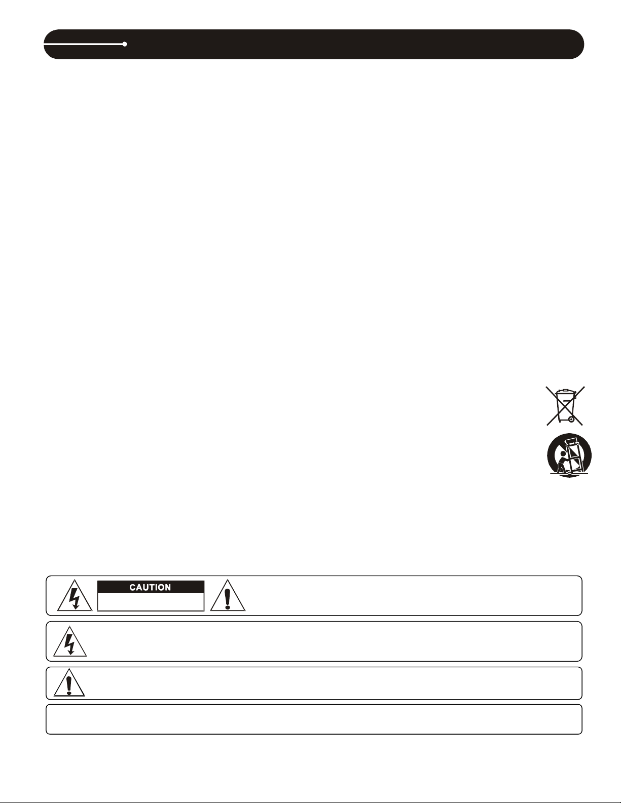
CAUTION: To prevent electric shock, do not use this polarized plug with an extension cord, receptacle or other outlet
unless the blades can be fully inserted to prevent blade exposure.
RISK OF ELECTRIC SHOCK
DO NOT OPEN
The lightning flash with arrowhead symbol within the equilateral triangle is intended to alert the use to the
presence of un-insulated “dangerous voltage” within the product’s enclosure that may be of sufficient
ma
gnitude to constitute a risk of electric shock.
The exclamation point within the equilateral triangle is intended to alert the user to the presence of important
operation and maintenance (servicing) instructions in the literature accompanying this appliance.
CAUTION: To reduce the risk of electric shock, do not remove any
cover. No user-serviceable parts inside. Refer servicing to qualified
service
16. Servicing –The user should not attempt any service to the appliance
beyond that described in the operating instructions. All other servicing
should be referred to qualified service personnel..
17. Ventilation – Slots and openings in the cabinet are provided for
ventilation and to ensure reliable operation of the product and to
protect it from overheating, and these openings must not be blocked
or covered. The openings should never be blocked by placing the
product on a bed, sofa, rug, or other similar surface. This product
should not be placed in a built-in installation such as a bookcase or
rack unless proper ventilation is the manufacturer’s instructions have
been adhered to.
18. Attachments – do not use attachments not recommended by the product
manufacturer as they may cause hazards.
19. Accessories – Do not place this product on an unstable cart, stand,
tripod, bracket, or table. The product may fall, causing serious injury
to a child or adult, and serious damage to the product. Use only with a
cart, stand, tripod, bracket, or table recommended by the
manufacturer, or sold with the product. Any mounting of the product
should follow the manufacturer’s instructions, and should use
amounting accessory recommended by the manufacturer.
20. Lightning – For added protection for this product during a lightning
storm, or when it is left unattended and unused for long periods of time,
unplug it from the wall outlet and disconnect the antenna or cable
sy
stem. This will prevent damage to the product due to lightning and
power-line surges.
21. Replacement Parts – When replacement parts are required, be sure
the service technician has used replacement parts specified by the
manufacturer or have the same characteristics as the original part.
Unauthorized substitutions may result in fire, electric shock, or other
hazards.
22. Safety Check – Upon completion of any service or repairs to this
product, ask the service technician to perform safety checks to
determine that the product is in proper operating condition.
23. This product is in compliance with EUWEEE
regulations. Disposal of end of life product should not
be treated as municipal waste. Please refer to your
local regulations for instructions on proper disposal of
this product.
24. Carts and Stands – The appliance should be used only
with a cart or stand that is recommended by the
manufacturer. An appliance and cart combination
should be moved with care. Quick stops, excessive
.
force, and uneven surfaces may cause the appliance
and cart combination to overturn
personnel only.
2
Page 3

Handle the power cord carefully.
Do not let foreign objects in the set
Hold the plug when unplugging the cord.
Never disassemble or modify the set in any way.
Keep the set free from moisture, water, and dust
Allow for sufficient heat dispersion when installed on a rack.
Do not obstruct the ventilation holes. (For sets with ventilation holes.)
Unplug the power cord when not using the set for long periods of time
Do not let insecticides, benzene, and thinner come in contact with the set.
NOTE ON USE
FEATURES
Auto cue
Pitch display
Frame search
Real-time cue
4 different speed scan
Digital Output RCA coaxial
Pitch Range: +/-4%, +/-8%, +/-16%
8 times oversampling 1 bit D/A converter
Visit www.stantondj.com for downloadable updates, videos, and news about this product.
3
Page 4

1
1
CONTROLS OVERVIEW CONTROL PANEL
1
1
2
3
0
4
6
5 9
7
8
1. EJECT- Opens the CD door.
2. STOP- Stops the CD.
3. SKIP- Skips through the tracks on the CD, forward or back.
4.
- Scans forward or back through the current track. This unit
features 4 scan speeds. Keep the
few seconds to change the scan speed.
5. PLAY/PAUSE- Plays or pauses the CD. Autocue function sets the
cue point automatically when this button is used.
6. CUE- Used to recall and preview the cue point.
7. TIME- LCD display reads the time remaining or time elapsed,
according to this button.
or button pressed for a
8. PITCH
PITCH BUTTON- Turns pitch fader ON and OFF.
PITCH BEND- Maximum pitch on this unit is 16%. If the pitch fader
is already physically set to 16%, this function will not work.
Pressing the PITCH and PITCHBEND-(minus) buttons
simultaneously changes the pitch fader range between +/- 4,
8, and 16%.
9. +10- This button allows you to skip ahead by 10 tracks. Example: if
you are at Track #1, pressing this button will skip you to Track #11,
press the button again, it will skip to Track #21. If there are not that
many tracks, it will go back to Track #1.
10. SGL/CTN- Switches between Single or Continuous play modes.
11. PITCH FADER- Used to speed up or slow down current track.
4
Page 5

1 2
1. PHONES- Use this stereo jack to connect a pair of headphones.
2. AUDIO OUT- This stereo line output connects to the line input on
any DJ mixer.
CONTROLS OVERVIEW REAR PANEL
4
3
5
6
7
LCD DISPLAY
1. TRACK INDICATOR - This 3-digit indicator details a cur rent tr ack.
The number displayed in the track indicator is a direct reference to a
track being selected a track in play, pause, or cue mode.
2. TIME BAR INDICATOR - This bar visually details the time defined
in t he TIM E M ETE R (M , S , & F) As with the TIME METER this bar is
also dependent on the selected time function TOTAL REMAIN,
REMAIN or ELAPSED. This bar will begin to flash when 15 seconds
of a track remain and will begin to rap idly flash when three seconds of a
track remain. The flashing bar is a great visual reminder a track is
about to end. The flashing bar will function regardless of whi ch t ime
mode the unit is in.
1 3
75
642
3. DIGITALOUTPUT- This coaxial (S/PDIF) digital out-put connects to
any RCA, S/PDIF input, as found on most standard computer sound
cards or CD burners.
4. FADER START- Connects to any DJ mixer equipped with a fader
start input. This enables the user to start the CD from the cue point,
using the mixer’s cross or line fader, depending on the mixer.
5. VOLTAGE SELECTOR- Used to select the unit’s voltage according
to the local setting.
Note: The voltage should preset correctly from the factory, however,
make sure to check it before powering the unit.
✽ Just for Dual Voltage model only.
6. AC IN- This is the connection for the supplied power cable.
7. POWER- This button is used to power the unit ON and OFF
4. TOTAL REMAIN INDICATOR - This indicator is in direct reference to
the TIME METER. When the TOTAL REMAI N indi cator is di splaye d in
the LCD, the time defined will refer to a disc's total remaining time.
The time mode is changed by tapping on TIME button.
5. REMAIN INDICATOR - This indica tor is in direc t reference to the TIME
METER. When the REMAIN indicator is displayed in the LCD, the
time defined will refer to a single track's remaining time . T he ti me mode is
changed by tapping on TIME button.
6. SINGLE INDICATOR - This indicates the unit is in single play mode,
the unit will play a single and return to CUE mode. If the single
indicator is not displayed the unit is in continuous mode. In
continuous mode the drive will play through all the tracks on the
disc.
7. PITCH METER - This meter displays the pitch percentage being
applied to playback by the PITCH SLIDER If the meter read zero
regardless of the PITCH SLIDER'S position, the PITCH function is
not activated.
3. TIME DISPLAY - These indicators detail the Minutes, Seconds, and
Frames. The meter will display either the elapsed time, or remaining
time of a track. The time displayed in the meter will directly reflect
the time indicator.
5
Page 6

SPECIFICATIONS
GENERAL Model: S.300
Table top CD/ MP3 Player
System Compact Disc Digital Audio
Disc loading TOP loading
Display 12 Digital LCD Display
Dimensions: 216(W) x 275(D) x 93(H)mm
Weight: 2.0Kgs
Power supply: Dual Voltage: AC 115V~60Hz/230V~50Hz, User Selectable
Single Voltage: AC 100V, 50/60Hz (For Japan)
AC 110V, 60Hz (For Taiwan)
AC 120V, 60Hz (For U.S.A., Canada, Mexico)
AC 220V, 50Hz (For United Arab Emirates, Chile, Argentina)
AC 220V, 60Hz (For Philippines)
AC 230V, 50Hz (For Europe, New Zealand, South Africa, Singapore, Israel)
AC 240V, 50Hz (For Australia, U.K.)
Power consumption: 15W
Pitch control range: Within +/-4%, +/-8%, +/-16%
Pitch bend: +/-4%, +/-8%, +/-16%
Pitch accuracy: +/- 0.15%
Environmental conditions: Operational temperature: 5 to 35˚C (41 to 95˚F)
Operational humidity: 25 to 85% RH (non-condensation)
Storage temperature: -20 to 60˚C (4 to 140˚F)
Accessories: 2P RCA path cord L/R 1 pairs
Auto-start cable 1 pc
Operating Instruction 1 pc
AC power cord 1 pc
AUDIO CHARACTERISTICS (TEST DISC: TCD-782, LOAD=47Kohm)
ITEM TYPICAL LIMIT CONDITION
Output level 2Vrms+/-0.5dB 2Vrms +/-1dB 1KHz,0dB
Channel balance WITHIN 0.5dB WITHIN 1dB 1KHz,0dB
Frequency response 20-20KHz +/-0.5dB 20-20KHz +/-1dB 0dB OUTPUT
De-emphasis -20dB +/-0.3dB -20dB +/-1dB 16KHz, -20dB
Channel separation(*2) 93dB 85dB 1KHz,0dB
THD + N(*1) 0.01% 0.03% 1KHz,0dB
S/N (*2)* 93dB 85dB 1KHz.0dB
DIGITAL OUTPUT: 0.5 +/-0.1V P-P 1KHz, 0dB
PHONES OUTPUT LEVEL: 220mV +/-1dB 220mV +/-3dB 1KHz, 0dB, LOAD=32 OHM
NOTE: *1: WITH 20KHz LOW PASS FILTER.
*2: WITH 20KHz LOW PASS FILTER AND "IHF-A" WEIGHTED.
SEARCHING TIME (TEST DISC: TCD-792)
ITEM TYPICAL LIMITS CONDITION
Short access time 2 sec 4 sec Play next track
Long access time 4 sec 6 sec Track 1 ->Track 20
Track 20 ->Track 1
PLAYABILITY
ITEM TYPICAL LIMIT CONDITION
Interruption 1mm 0.7mm TCD-725
Black dot 1mm 0.6mm TCD-725
Finger prints 75um 65um TCD-725
Eccentricity 140um 140um TCD-712 W/O TRACK JUMP
Vertical deviation 1mm 0.5mm TCD-731R
PICK-UP (SONY KSM-213CCM)
System Object lens drive system optical pick-up
Object lens drive system 2 dimensional parallel drive
Tracking detection 3 spot beam detection
Optical source Semiconductor laser
Wave length 780nm
NOTES:
(1) The specifications are subject to change to any improvement by negotiations in advance.
(2) The parts are subject to change to any improvement within the range of the specifications.
6
Page 7

SPECIFICATIONS
MP3 FORMAT
Disc Format
MP3 Format
Note #1: max.255 files each folder
Applicable file extensions mp3 . MP3 . mP3 . Mp3
ISO9660 max. 63 characters
Joliet max. 63 characters
CD-ROM sector format mode-1 only
Max. number of Folders 255
Max. number of files max. 999 files (* note #1)
MPEG 1 Layer 3 standard (ISO/IEC 11172-3),
which provides for single channel (‘mono’) and
two-channel (‘stereo’) coding at sampling rates of
32, 44.1 and 48kHz.
MPEG 2 Layer 3 standard (ISO/IEC 13818-3),
which provides for similar coding at sampling rates
of 16, 22.05 and 24 kHz.
MPEG 2.5 Layer 3 standard, which provides for
similar coding at sampling rates of 8, 11.025 and 12
kHz.
Disc at Once and Track at Once Disc Writing Method
Multi Session
32/40/48/56/80/96/112/128/160/192/224/256/320 kbps
Xing/VBRI VBR
32/40/48/56/64/80/96/112/144/160 Kbps
32/40/48/56/64/80/96/112/144/160 Kbps
st
session is CDDA, you can playback Only CDDA track,
If the 1
st
session is MP3, you can playback only MP3 file.
If the 1
7
Page 8

WARRANTY & RETURN POLICY
Warranty
Through Stanton’s authorized dealers around the World, Stanton, or one of Stanton’s authorized distributors outside the U.S., will, without charge, repair
or replace, at the sole discretion of the entity responsible for making the repair or providing the replacement, any Stanton merchandise proved defective
in material or workmanship for a period of one (1) year following the date of original purchase. Exceptions to this warranty are as noted below:
The warranty for mechanical parts which are subject to wear and tear are limited to the earlier to occur of thirty (30) days following the date of original
purchase or the following number of cycles: Faders - 15,000; Rotary potentiometers - 10,000; and Switches - 10,000.
Stanton will warrant all replacement parts and repairs for ninety (90) days from the date of original shipment. Repairs made necessary by reason of misuse, alteration, normal wear, or accident are not covered under this warranty.
Returns
Authorized Stanton dealers are only authorized to sell and distribute merchandise within a specific country. All goods requiring warranty repair or replacement must be returned (freight prepaid if not hand-delivered) to the authorized Stanton dealer from whom the merchandise was purchased and in the
same country where the merchandise was purchased. For purposes of purchases made via the Internet, the merchandise must be returned to the authorized Stanton dealer in the country where the authorized Stanton dealer which sold the merchandise to purchaser is located and not the authorized Stanton
dealer in the country where the purchaser is located or the country in which the merchandise was received. Any returns to a non-authorized dealer or to
an authorized Stanton dealer not in the same country as the merchandise was intended to be sold or as set forth above will void this warranty.
To initiate a warranty repair, you must contact the authorized Stanton dealer from whom you purchased the merchandise, and follow such authorized
Stanton dealer’s return policy.
Stanton assumes no risk and shall be subject to no liability for damages or loss resulting from the specific use or application made of the merchandise.
Stanton’s liability for any claim, whether based on breach of contract, negligence, infringement of any rights of any party, or product liability, and relating
to the merchandise shall not exceed the price received by Stanton from your purchase of such merchandise. In no event will Stanton be liable for any
special, incidental or consequential damages (including loss of use, loss of profit and claims of third parties) however caused, whether by the negligence
of Stanton or otherwise. To the extent permitted by law and except as otherwise provided above, Stanton disclaims any express or implied warranties of
merchantability or fitness for a particular purpose.
The above warranty provides you with specific legal rights. You may also have additional rights, which are subject to variation from state to state and
country to country.
If there is a dispute regarding the warranty of merchandise that does not fall under the warranty conditions stated above, please include a written explanation with the merchandise when returned pursuant to the terms and conditions set forth herein.
Please register your product online at www.stantondj.com or mail your completed warranty card to:
Stanton Magnetics, Inc, 3000 SW 42 St. Hollywood, Florida 33312.
Page 9

Page 10

 Loading...