

RM.404
Professional DJ Mixer
OWNER’S MANUAL
STANTON MAGNETICS, Inc.
information@stantondj.com
©2004 Stanton Magnetics, Inc.

Please read carefully before use of this product
Failure to follow the instructions printed below may void warranty
• Follow all security advice printed on your mixer
• When removing the unit's AC plug from the power source, grasp
and pull the plug, NEVER the cord itself!
• Avoid placing your mixer near heat sources, such as power amplifiers.
• When in use, place your mixer on a stable surface, away from vibration.
Always use care when carrying your mixer. Impact, or heavy vibration may
compromise the unit's mechanical integrity. The manufacturer is not
responsible for damage resulting from an impact, or misuse.
• When in use, place your mixer away from sources of hum or noise, such
as transformers, or electric motors.
• To prevent overheating, always provide your mixer with adequate ventilation air space.
• Avoid stepping on your mixer's AC cord. Repeated compression of the
cord may lead to electrical shorting.
• To avoid damage due to AC voltage peaks, always disconnect your mixer
from the power source during electrical storms.
• Your mixer contains no user-serviceable parts except for the crossfader.
The manufactureris not responsible for any damage or personal injury
resulting from unauthorized user-servicing or modifications. In addition,
the warranty will be void if any unauthorized service by the user is detected. Always return you mixer to an authorized Stanton dealer for servicing.

Welcome
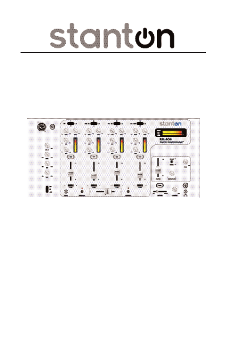
Congratulations and thank-you for purchasing the latest addition to the growing Stanton family. Sporting a new attitude, and a fresh, modern look, the
RM.404 is a 4-channel, rackmount mixer loaded with features and innovations giving club and mobile DJs a powerful, yet simple tool to mix, create,
and perform their best. 1/4" and 1/8" headphone outputs, XLR, RCA, and
1/4" Master and Zone outputs, plus plenty of inputs, including one Mic input,
and a separate 1/8" jack for connecting portable devices such as iPods
ensure the utmost in flexibility. Colored, backlit knobs, separate LED level
indicators, gain and 3-band EQs on every channel with a fully assignable
Crossfader, offer increased control and functionality. Thoughtfully designed
and engineered to give you the most intuitive and instinctual experience possible, the RM.404 delivers all these features in a logical layout with quality
components, all at an affordable price.
Stanton's revolutionary Superior Sound Technology (SST™) also gives the
RM.404 exceptional sound quality with audio specifications rivaling mixers
costing up to four times as much. Developed from the ground up by a team
of seasoned audio professionals who have designed world class professional recording studio and broadcast mixers, working hand in hand with experienced and respected DJs, SST™ delivers a dynamic range better than 110
dB through ultra low-noise circuitry with a lower total harmonic distortion
(THD) than other mixers in its class. Glass epoxy PC boards, surface mount
technology, and faders that don't bleed add to the superior construction standards. This equates to a cleaner, more transparent sound, allowing your
music to be heard the way it was meant to. We’re proud to bring you the new
look, feel and sound of Stanton.
TM
,
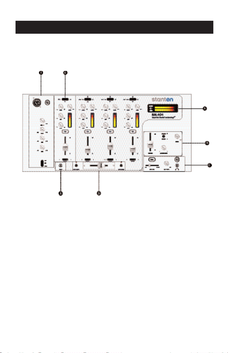
RM.404 Top Panel (FUNCTIONS)
The controls and functions of the RM.404 are grouped in alphabetical sections (clockwise from upper right corner) for your reference and then listed
numerically for more detail.
Section A: Output Meters
Section B: Output Controls
Section C: Cue Controls
Section D: Crossfader Controls
Section E: MP3 / Aux In
Section F: Mic Controls
Section G: Channel Controls

RM.404 Top Panel (FUNCTIONS)
Section A: Output Meters
1. Meter Switch: Switches the display of the Level Meter (#2) between
Master or Zone output signals.
2. Level Meter: Displays the left and right Master or Zone output level of the
mixer. Red indicates clipping.
RM.404 Top Panel (FUNCTIONS)
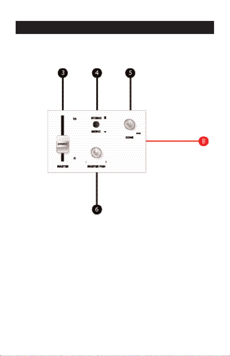
Section B: Output Controls
3. Master Level: Controls the overall output level of the audio signal sent
through the Master connectors (see Output Connections.)
4. Stereo/Mono Switch: Switches the Master output between a stereo or
mono signal. Mono mode can be used to accommodate some large PA systems. It can also be engaged in the event of a sudden loss of stereo signal
in phonograph cartridge connections [Stereo = UP position.]
5. Zone Level: Controls the output level of the audio signal sent through the
Zone connectors (see Output Connections.)
6. Master Pan: Controls left/right signal balance of the Master Output (#3.)

RM.404 Top Panel (FUNCTIONS)
Section C: Cue Controls
7. Split Cue: Controls how the CUE will be heard in the headphones. In the "stereo"
position, the pre-selected Cue (#29) will be heard as a stereo signal in the headphones (full stereo audio signal in both ears.) In "split" position, the pre-selected Cue
(#29) will be heard on one side of the headphones, while the Master Output (#3) signal is heard on the other side (different audio signals in each ear.)
8. Headphone Output 1: Connection for 1/4 inch headphone (phono-jack.)
Recommended headphone impedance is 32-200 ohms for maximum volume.
9. Headphone Output 2: Connection for 1/8 inch headphone (mini-jack.)
Recommended headphone impedance is 32-200 ohms for maximum volume.
10. Cue Level: Controls the overall headphone output level of both output jacks. It is
recommended that headphones with an impedance rating of 200 ohms or less be
used for maximum volume.
11. Cue Pan: This controls the blend of audio signals that can be heard in the head
phones. In the left-most “Cue” position, only channels selected by the Cue
switches (#29) will be heard. In the right-most “Master” position, only signals being
sent to the Master Output (#3) will be heard in the headphones. Any setting inbetween provides a mix of both Cue and Master signals. This gives DJs the flexibility to choose how they wish to monitor audio signals, based on personal preference
and technique.
Assign
-
 Loading...